Fukuda Denshi Co LX7230G ECG & Respiration and SpO2 Transmitter User Manual Short Term Confidential
Fukuda Denshi Co Ltd ECG & Respiration and SpO2 Transmitter Short Term Confidential
(Short-Term Confidential) User Manual
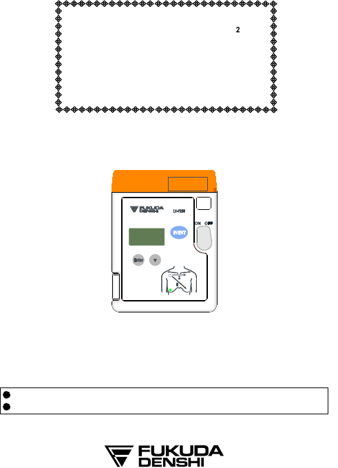
ECG, Respiration and SpO
Transmitter
LX-7230N
Ver.02
Operation Manual
LX-7230N
Before using the product, please read this manual thoroughly.
Store this manual where it can be always referred to.
TYPE:GHz
CAUTION
Federal Law restricts this device to sale by or on the order of a physician.
CAUTION
Users are advised to periodically contact the FCC or specified frequency
coordinator and determine if other or your transmitter frequencies that
may cause interference.
CAUTION
The manufacturers, installers and users of Wireless Medical Telemetry
System equipment are cautioned that the operation of this equipment
could result in harmful interference to other nearby medical devices.
CAUTION:
This equipment for sale by or on the order of a physician.
The company and product names used in this manual are trademarks or
registered trademarks.
If this manual has pages missing or out of order, contact Fukuda Denshi
for replacement.
Only physician or persons instructed by physicians are allowed to use the
equipment.
The information contained in this document is subject to change without
notice due to improvement in the equipment.
Copyright © 2012 by Fukuda Denshi Co., Ltd.
No part of this document may be copied or transmitted in any form without the prior
written permission of Fukuda Denshi Co., Ltd.
Printed in Japan
This operation manual is for the LX-7230 Ver. 02.
Thank you for purchasing this product.
Before using this product, read this operation manual thoroughly for
correct handling and operation.
Safety Precautions
Read the “Safety Precautions” thoroughly before use to ensure correct and
safe use of the product.
Make sure to follow the precautions indicated below, as these are important
messages related to safety.
DANGE R
Failure to follow this message may cause immediate
threat of death or serious injury.
WARN I N G
Failure to follow this message may result in death or
serious injury.
CAUTI O N
Failure to follow this message may cause injury or
failure to the equipment.
NOTE
A note is not related to product safety, but provides
information about the correct use and operating
procedures to prevent incorrect operation and
malfunction of the equipment.
Precaution from Fukuda Denshi
Fukuda Denshi is liable for the safety, reliability, and performance of its
equipment only if;
Maintenance, modifications, and repairs are carried out by authorized
personnel.
Components are used in accordance with Fukuda Denshi operating
instructions.
If the equipment is used incorrectly and become unusable, Fukuda Denshi is
not liable for the malfunction. Use the equipment only for the purpose specified
in this manual.
Graphic Symbols
Refer to the following symbols indicated on the LX-7230N for their meanings.
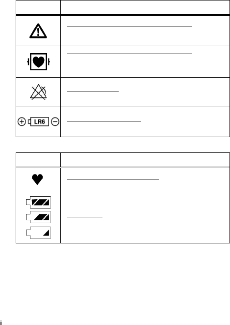
Symbols indicated on the main unit
Symbol Description
Caution: Refer To Accompanying Documents
Indicates the need to refer to the related accompanying
documents before operation.
Type CF Applied Part with Defibrillation-Proof
Indicates that the degree of protection against electric
shock is Type CF Applied Part with defibrillation-proof.
No Alarm Function
Indicates no alarm function.
Battery Type and Direction
Indicates the battery type and direction.
Symbols indicated on the LCD screen
Symbol Description
Heart Rate Synchronization Mark
This mark flashes synchronizing to the heartbeat.
Battery Mark
Indicates the remaining battery level.

Precautions for Safe Operation of Medical Electrical Equipment
Cautions described here are regarding the general instructions for safety use
to the patient and users. As for cautions about the LX-7230N, please refer to
the following pages.
CAUTI O N
1. Users should have a thorough knowledge of the operation before
using this equipment.
2. Pay attention to the following when installing or storing the
equipment.
Do not install or store in an area where the equipment will be subject
to splashing water.
Do not install or store in an area where the environmental
conditions, such as atmospheric pressure, temperature, humidity,
ventilation, sunlight, dust, sodium, sulfur, will adversely affect the
system.
Place the equipment on a stable surface where there is no
inclination, vibration, or shock (including during transportation).
Do not install or store in an area where chemicals are stored or
gases are evolved.
3. Before operating the equipment, verify the following items.
Check the cable connection and polarity to ensure proper operation
of the equipment.
Ensure that all cables are firmly and safely connected. Especially,
recheck the attachment and connection condition of electrode and
the probe (sensor).
Pay special attention when the equipment is used in conjunction with
other equipment as it may cause erroneous judgment and danger.
Check the remaining battery level.
When replacing the battery, make sure that the battery polarity is
correct. Do not charge the battery.
4. During operation of the equipment, verify the following items.
Do not operate the equipment beyond the time period required for
diagnosis and medical care.
Do not pick up and/or swing the equipment pulling/grabbing the
probe (sensor) or cable part. It may damage the equipment and lead
to measurement error.
Always observe the equipment and patient to ensure safe operation
of the equipment.
If any abnormality is found on the equipment or patient, take
appropriate measures such as ceasing operation of the equipment
and/or detaching the probe (sensor) and/or electrode, in the safest
way for the patient.
Do not allow the patient to come in contact with other equipments.
5. After using the equipment, verify the following items.
Make sure to turn off the power of the equipment.
When unplugging the cables, do not apply excessive force on the
cable and pull from its connector.
Clean the accessories and cables, and keep them together in one
place.
Keep the equipment clean to ensure proper operation for the next
use.
Make sure to remove the batteries if the equipment is not used for a
long time. The leakage from the batteries may damage the
equipment or an explosion from the batteries may occur.
6. If the equipment is damaged and in need of repair, ensure patient
safety by immediately turning the equipment off and remove the
electrodes and/or probe from the patient. User should not
attempt service. Label the unit “OUT OF ORDER” and contact
Fukuda Denshi representative.
7. Do not remodel the equipment.
8. Maintenance Check
Make sure to periodically check the equipment, and accessories.
Before reusing the equipment that has been left unused for a while,
make sure that the equipment works normally and safely.
9. When using electrosurgical knives or defibrillator with this
equipment, take care of the following.
To prevent burn injury to the patient, verify proper attachment of
patient ground plate, ECG electrode type for the electrosurgical
knives, and the quantity of gel, output energy for the defibrillator.
Also, verify that a proper ground is selected.
Some types of equipment other than the above may cause
accidental hazards to the patient and operator due to the conditions
of the equipment
.
Read the operation manual attached to each
equipment and understand the precautionary instructions prior to
use.
Non-Explosion Proof
DANGE R
Never operate the equipment in the presence of flammable anesthetics,
high concentration of oxygen. It may cause an explosion or fire.
Never operate the equipment inside a hyperbaric chamber. It may
cause an explosion or fire.
Never operate the equipment where flammable gas or fluid such as
anesthetic, oxygen, and hydrogen are used. It may cause an explosion
or fire.
Precautions about Magnetic Resonance Imaging (MRI)
WARNI N G
Do not operate this equipment in magnetic resonance imaging (MRI)
environments.
When conducting MRI test, remove the electrodes and sensors
connected to the patient (test subject).
The local heating caused by the induced electromotive force may cause
burn injury to the patient (subject). For details, refer to the operation
manual for the MRI testing device.
Electrosurgery Safety
WARNI N G
When using electrosurgical instrument, make sure the contact between
the patient and the ground plate is secured. If the connection is
incomplete, the patient may suffer a burn at the electrode site.
When using an electrosurgical instrument, it may misidentify noise from
the electrosurgical instrument as a heartbeat or arrhythmia.
Defibrillation Safety
WARNI N G
Use only the lead cable specified by Fukuda Denshi when defibrillating.
If used by unspecified lead cable, the equipment may be damaged,
resulting in a safety hazard.
When using the defibrillator, keep away from the electrodes or
medicament applied to the patient chest. If this is not possible, remove
the electrodes or medicament before using it.
If the defibrillator paddles are directly in contact with the electrodes or
medicament, an electrical shock may result from the discharged energy.
When using the defibrillator, do not touch the patient and the metal part
of the equipment or cables. Electric shock may result from the
discharged energy.
Precautions about the Pacemaker
WARNI N G
Minute ventilation rate-adaptive implantable pacemakers can
occasionally interact with certain cardiac monitoring and diagnostic
equipment, causing the pacemakers to pace at their maximum
programmed rate. The cardiac monitoring and diagnostic equipment
may possibly send wrong information.
If such event occurs, disconnect the cardiac monitoring and diagnostic
equipment, or follow the procedures described in the operation manual
of the pacemaker.
(For more details, contact FUKUDA DENSHI personnel, your
institution’s professionals, or your pacemaker distributors.)
ECG meter may continue to count the pacemaker rate during
occurrences of cardiac arrest or arrhythmias. Do not rely entirely upon
the ECG meter alarms. Keep pacemaker patients under close
surveillance. Check this manual for disclosure of the pacemaker pulse
rejection capability of this equipment.
Precautions about the LX-7230N
WARNI N G
Do not connect cables not authorized by Fukuda Denshi to any I/O
connector. If done so by mistake, the LX-7230N cannot deliver its
maximum performance and may be damaged, resulting in a safety
hazard.
Do not use this equipment with multiple patients simultaneously.
This equipment itself has no alarm function. Do not use it if an alarm
function is necessary. The alarm function with the receiving monitor,
refer to the operation manual of the receiving monitor.
CAUTI O N
Do not pick up and/or swing the LX-7230N pulling/grabbing the probe
(sensor) or cord part. The cable could break or get disconnected from the
LX-7230N. And it may hit people or damage other equipment around.
Precautions about Waterproof
CAUTI O N
Replace the “Battery Compartment Lid” of the LX-7230N regularly to
keep the performance of waterproof. If not regularly replaced, the quality
of the lid will deteriorate and cannot keep the waterproof performance.
For details about the regular replacement, contact your local Fukuda
Denshi service representative.
The lid may be damaged from high impact. If the LX-7230N is dropped
or is subjected to a high impact, make sure that the lid is not damaged.
However, the SpO probes (sensors) are not waterproof. Do not take a
bath with them, and ensure to be away from liquid.
Do not use the LX-7230N wet. Always wipe the LX-7230N with a soft
cloth and dry it thoroughly before use.
Precautions about ECG
CAUTI O N
When removing electrodes from the patient, remove them carefully and
slowly. Do not apply excessive force to remove them. Otherwise, it may
damage the skin.
There are some cases when the pacemaker pulse cannot be detected
depending on the pacemaker type, pulse voltage, pulse width, electrode
lead type (unipolar, bipolar), electrode placement, or lead method which
causes the pacemaker pulse amplitude to decrease and disables
pacemaker pulse detection.
If signals similar to a pacemaker pulse are present, such as electric
blanket noise or excessive AC frequency noise, these may be
erroneously detected and displayed as a pacemaker pulse. In this case,
check the condition of the electrodes and ECG lead cable to resolve the
cause or turn off the pacemaker detection setting on the receiving
monitor.
Precautions about SpO
WARNI N G
During SpO monitoring, always use the probe (sensor) specified by
Fukuda Denshi. If any other probe (sensor) is used, a high temperature
rise of the probe (sensor) may place the patient in danger of burns in
the worst case.
When the SpO probe (sensor) is in a connector-off condition, the SpO
alarm will not be generated on the receiving monitor. Make sure that the
SpO probe (sensor) is securely connected. If the SpO
waveform/numeric data is not displayed, check the patient’s condition
and pay attention not to miss the connector-off condition.
When measuring the SpO of a patient with high fever or peripheral
circulatory insufficiency, check the probe (sensor) attachment
periodically and change the attachment site. The temperature of the
attachment site will rise 2 to 3 C due to the sensor heat which may
result in compression necrosis and burn injury.
Even a short duration of attachment may inhibit the blood flow and
generate compression necrosis and burn injury.
When securing the probe (sensor) with tape, do not apply the tape too
tight. At the same time, check the blood flow constantly so that
congestion is not generated at the peripheral. When removing the tape,
remove it slowly with care not to damage the patient’s skin.
CAUTI O N
For the following case, accurate measurement may not be possible.
Patient with excessive abnormal hemoglobin (COHb, MetHb)
Patient with the pigment injected to the blood
Patient receiving CPR treatment
Placement of SpO probe (sensor) on limb with a blood-pressure cuff,
arterial catheter, or intravascular line
When measuring at placement position with venous pulse
Patient with body motion
Patient with small pulse
Excessive body motion (patient’s motion)
Excessive light (direct sunlight, fluorescent, light therapy equipment,
surgical light, infrared heat ramp, etc.)
External colorant such as nail polish
Abnormally low or high hemoglobin concentration
Electrosurgery
Influence of electromagnetic waves from other electronics devices
High-intensity radio waves from mobile phones
Precautions about Output Signal
WARNI N G
Do not use the output signal of the monitor that receives radio wave signal
from the LX-7230N as the trigger signal for IABP, MRI echocardiographic,
or defibrillator for the following reasons.
It may lead to a delay of operating timing due to the delay time of
waveform transmission.
A trigger signal unrelated to the heart rate may be generated due to
the interfusion of spike noise at weak electric field.
Precautions about Accessories and Optional Accessories
WARNI N G
Use only the accessories, such as ECG Lead cable and SpO probe
(sensor), specified by Fukuda Denshi for the LX-7230N. Otherwise, the LX-
7230N cannot deliver its maximum performance and may be damaged,
resulting in a safety hazard.
CAUTI O N
Do not reuse disposable products.
Store the disposable products properly as mentioned in their user
manuals.
Precautions about Battery
WARNI N G
Use new "AA" size (“LR06” size) alkaline cell.
Install the battery with the correct polarity.
Do not charge the battery. Any attempt to charge the battery may cause
it to leak or break.
Do not short the (+) and (-) terminals. It may result in exothermic heat
and fire.
Do not throw the battery into fire. It may explode.
Precautions about Disposing of Equipment, Accessories, or
Components
CAUTI O N
When disposing of the equipment, accessories, or components, use an
industrial waste distributor. Do not dispose of as ordinary waste.
Used disposal items (ECG electrodes, etc.) shall be discarded as
medical waste.
Precautions about Disposing of Battery
CAUTI O N
Obey the local municipal rule to dispose the used dry cell battery.
Precautions for Use of Medical Telemeter
WARNIN G
The LX-7230N transmitter must not be co-located or operated in
conjunction with any other antenna or transmitter.
The LX-7230N complies with FCC radiation exposure limits set forth for
a controlled environment and meets the FCC radio frequency (RF)
Exposure Guidelines. The LX-7230N has very low levels of RF energy
that are deemed to comply without testing of specific absorption ratio
(SAR).
Operation of LX-7230N requires the prior coordination with a frequency
coordinator designated by the FCC for the Wireless Medical Telemetry
Service.
This radio frequency device is susceptible to interference from outside
sources. Interference may prevent the monitoring of patients connected
to this equipment. If a problem exists, contact your local service
representative.
The LX-7230N transmits vital signs to the receiving monitor using radio
wave signal. Under unstable radio wave signals, the receiving monitor
will not generate any alarms. This situation may miss sudden change in
the patient's condition and may cause a serious accident. Under
unstable radio wave signals, check the patient status consistently under
this situation. To get stable radio wave signals, make sure to have a
proper telemetry installation.
CAUTION
For installation, make sure the following.
The medical institution (hereinafter referred to as the “Institution”) must
decide the telemetry installation plan for the medical department in order
to prevent interference and interference between transmitters (telemetry

based on destination country’s radio law). When telemetry has already
been installed and been used, radio format, frequency, and antenna power
are required to be examined to prevent interference.
When using telemetry, which requires zone location, the Institution is to
set up the zones as an operation unit for each transmitter to prevent
electronic interference between telemetry throughout the Institution.
When using telemetry, which requires zone location, display and identify
each prepared zone in the equipment.
When laying receiver antenna for each transmitter, the Institution has to
examine the installation so that electronic interference does not occur.
Based on the above examination result, the Institution should install each
receiver antenna as required.
For management, make sure to follow the precautions below.
The Institution should appoint a person (hereinafter referred to as the
“Overall Manager”) to manage the wireless channels for the whole
Institution.
And when using telemetry, which requires zone location, the Institution
should nominate a person (hereinafter referred to as the “Zone Manager”)
to manage the wireless channels in each zone. However, when using such
telemetry in a local Institution, one person can perform both functions.
The Overall Manager and Zone Manager must be selected from people
who understand the characteristics and functionality of telemetry systems,
and are skilled in operating telemetry.
When installing telemetry, the Overall Manager and the Zone Manager
have to understand the precautions for use of telemetry in advance.
The Overall Manager is responsible for maintenance of wireless channel
and storage and maintenance of telemeter in the overall medical facilities
to give proper instructions to the Zone Manager when using telemetry
needing zone alignment, and to the telemetry user when using telemetry
not-needing zone alignment.
The Overall Manager should create a management log (hereinafter
referred to as the “log”), which contains a list of the management status of
the wireless channels for the whole Institution. When changing a wireless
channel, register it in the log and give proper instructions to the Zone
Manager or to the user.
The Zone Manager assumes responsibility for managing the wireless
channels, storing, and managing telemetry.
The Zone Manager assigns the transmitter to the user, and provides
enough education for use inside the zone.
The telemetry user verifies operation of the transmitter/receiver before
use.
The telemetry user, if using the telemetry in a zone location, follows the
instructions of the Zone Manager for the zone and gives instructions to the
patient if required.
When interference or breakdown occurs in telemetry communication, the
user is required to inform the Zone Manager and the Overall Manager of
the problems. The Zone Manager and Overall Manager are to deal with
the problem properly and/or contact their nearest Fukuda Denshi
representative for service.
Electromagnetic Compatibility
The performance of this equipment under electromagnetic environment
complies with IEC 60601-1-2 (2007).
Precautions for Safe Operation under Electromagnetic Influence
CAUTIO N
If any sorts of electromagnetic wave, magnetic field, or static electricity
exist around the equipment, noise interference or malfunction of the
equipment may occur. If any unintended malfunction or noise occurs
during monitoring, check the magnetic influence and take appropriate
countermeasures.
The following are examples of the common cause and countermeasures.
Mobile Phone
The radio wave may cause malfunction to the equipment.
Mobile phones and radio sets should be turned off in the room
(building) where medical device is located.
Static Electricity
In a dry environment (room), static electricity is likely to occur. Take
the following countermeasures.
Both operator and patient should remove any static electricity before
entering the room
Humidify the room

EMC Guidance
This equipment complies with IEC 60601-1-2 (2007). However, if portable
transmitter or wireless LAN equipment is used extremely nearby, the
electromagnetic influence may largely exceed the compliance level and may
cause unexpected phenomenon such as noise interference on the waveform,
etc.
Therefore, this equipment should be used in a location specified by each
medical institution. If any unexpected noise interference on the waveform or
failure to the peripheral device occurs, stop using the equipment and follow the
instruction of the technician.
The following is the information relating to EMC (Electromagnetic
Compatibility).
(When using this equipment, verify that it is used within the environment
specified below.)
Compliance to the Electromagnetic Emissions
The LX-7230N is intended for use in the electromagnetic environment
specified below. The customer or the user of the LX-7230N should assure that
it is used in such an environment.
Emission Test Compliance
Electromagnetic Environment –
Guidance
RF Emission
CISPR 11 Group 1
The LX-7230N uses RF energy only for
its internal function. Therefore, its RF
emissions are very low and are not likely
to cause any interference in nearby
electronic equipment.
RF Emission
CISPR 11 Class A
This LX-7230N is suitable for use in all
establishments other than domestic
establishments.
Harmonic Emission
IEC 61000-3-2 N/A
Voltage Limit /
Flicker Emission
IEC 61000-3-3
N/A
Compliance to the Electromagnetic Immunity (1)
The LX-7230N is intended for use in the electromagnetic environment
specified below. The customer or the user of the LX-7230N should assure that
it is used in such an environment.
Immunity Test
IEC 60601-1-2
Test Level
Compliance
Level
Electromagnetic
Environment
Guidance
Electrostatic
Discharge
(ESD)
IEC 61000-4-2
±6kV contact
±8kV air
±6kV contact
±8kV air
Floors should be
wood, concrete or
ceramic tile. If floors
are covered with
synthetic material, the
relative humidity
should be at least
30%.
Electrical fast
transient/burst
IEC 61000-4-4
±2kV:
Power supply lines
±1kV:
Input/output lines
N/A
Surge
IEC 61000-4-5
±1kV:
differential mode
±2kV:
common mode
N/A
Voltage dips,
short
interruptions
and voltage
variations on
power supply
input lines.
IEC 61000-4-11
<5% U
(>95% dip in U )
for 0.5 cycle
40% U
(60% dip in U )
for 5 cycles
70% U
(30% dip in U )
for 25 cycles
<5% U
(>95% dip in U )
for 5sec.
N/A
Power
Frequency
(50/60Hz)
Magnetic Field
IEC 61000-4-8
3A/m 3A/m
Power frequency
magnetic fields should
be at levels
characteristic of a
typical location in a
typical commercial or
hospital environment.
U is the AC mains voltage prior to application of the test level.
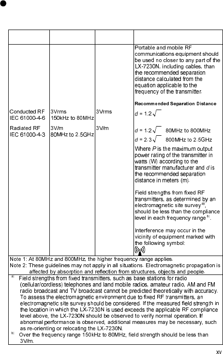
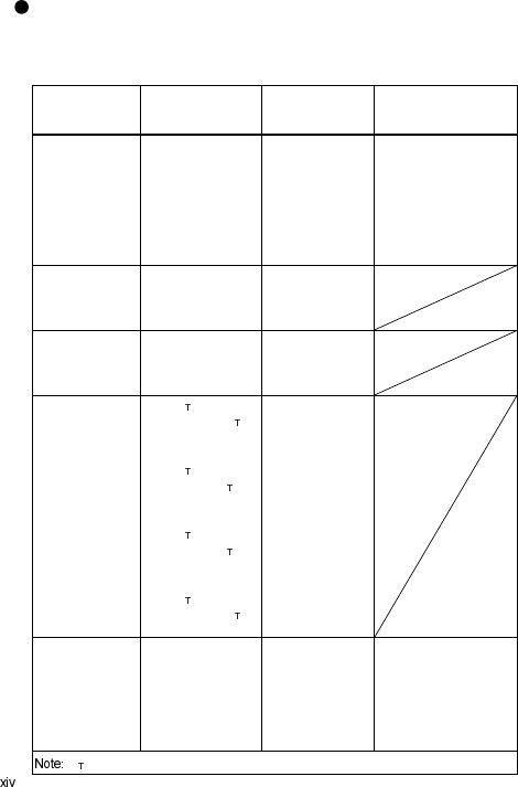
Compliance to the Electromagnetic Immunity (2)
The LX-7230N is intended for use in the electromagnetic environment
specified below. The customer or the user of the LX-7230N should assure that
it is used in such an environment.
Immunity
Test
IEC60601-1-2
Test Level
Compliance
Level
Electromagnetic Environment
Guidance
P
P
P
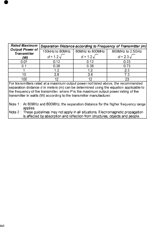
Recommended Separation Distances between Portable and
Mobile RF Communications Equipment and the LX-7230N
The LX-7230N is intended for use in an environment in which radiated RF
disturbances are controlled. The customer or the user of the LX-7230N can
help prevent electromagnetic interference by maintaining a minimum distance
between portable and mobile RF communications equipment (transmitters)
and the LX-7230N as recommended below, according to the maximum output
power of the communications equipment.
P P P

CONTENTS
Safety Precautions ..................................................................................... i
Precaution from Fukuda Denshi ....................................................... i
Graphic Symbols .............................................................................. ii
Precautions for Safe Operation of Medical Electrical Equipment .... iii
Non-Explosion Proof ....................................................................... iv
Precautions about Magnetic Resonance Imaging (MRI) ................. v
Electrosurgery Safety ...................................................................... v
Defibrillation Safety ......................................................................... v
Precautions about the Pacemaker .................................................. vi
Precautions about the LX-7230N .................................................... vi
Precautions about Waterproof ....................................................... vii
Precautions about ECG ................................................................. vii
Precautions about SpO ................................................................ viii
Precautions about Output Signal .................................................... ix
Precautions about Accessories and Optional Accessories ............. ix
Precautions about Battery ............................................................... ix
Precautions about Disposing of Equipment, Accessories,
or Components ........................................................................... x
Precautions about Disposing of Battery .......................................... x
Precautions for Use of Medical Telemeter ...................................... x
Electromagnetic Compatibility ............................................................ xii
Precautions for Safe Operation under Electromagnetic Influence .. xii
EMC Guidance .............................................................................. xiii
1. General Description ............................................................................. 1
2. Names of Parts and Their Functions .................................................... 3
3. Preparation .......................................................................................... 5
1) Installing the Batteries ................................................................ 5
2) Operating Power Switch ............................................................. 7
4. ECG Monitoring ................................................................................... 9
Connecting the ECG Lead Cable and Electrodes ...................... 9
Attaching the Electrodes .......................................................... 12
Connecting the ECG Lead Cable to the LX-7230N ................. 13
5. Respiration Monitoring ....................................................................... 15
6. SpO Monitoring ................................................................................. 17
SpO Monitoring ............................................................................ 18
7. Measurement ..................................................................................... 35
Starting Screen ........................................................................ 35
Waveform Display Screen ....................................................... 35
Battery Level Check ................................................................ 37
Waveform Display ................................................................... 37
8. Operation ........................................................................................... 47
Changing Setup ....................................................................... 47
Restarting the LCD display ...................................................... 51
Pressing the EVENT button ..................................................... 51
9. Other Setting Items ............................................................................ 53
Changing the Time Constant ................................................... 54
Changing the Detection Sensitivity of the Pacemaker Pulse ... 55
Changing the Respiration Detection Signal ON/OFF ............... 56
Changing the LCD Contrast ..................................................... 56
10. Changing the Transmitter Channel and Group ID ............................ 57
Changing the Transmitter Channel .......................................... 57
Changing the Group ID ............................................................ 57
11. Troubleshooting ............................................................................... 59
List of Displayed messages ..................................................... 59
Troubleshooting ....................................................................... 61
In Case of Dropping the LX-7230N into Water ........................ 63
12. Cleaning and Disinfection ................................................................ 65
Cleaning and Disinfecting the LX-7230N ................................. 65
Cleaning the ECG lead cable .................................................. 66
Cleaning and Disinfecting the SpO probe (sensor) ................ 66
13. Maintenance and Inspection ............................................................ 67
14. Standard and Optional Accessories ................................................. 69
Standard Accessories .............................................................. 69
Optional Accessories ............................................................... 70
15. Specification ..................................................................................... 73
Specification ............................................................................ 73
Functional Testers and Patient Simulator for SpO
measurement ........................................................................... 76
Displays ................................................................................... 77
Details of the “ELECTRODE?” Message ................................. 79
List of Setup Items ................................................................... 80
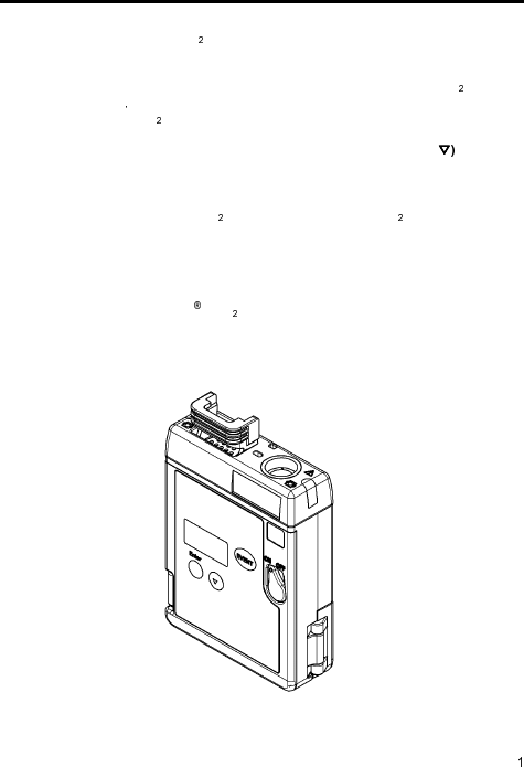
1. General Description
The LX-7230N is a radio telemetry transmitter designed to measure the ECG,
respiration waveform, SpO (functional oxygen saturation of arterial
hemoglobin), pulse waveform with two “AA” size (“LR06” size) alkaline
batteries.
Information such as ECG measurements, respiration waveform, SpO
measurements pulse waveform, battery level, and the conditions of the ECG
electrodes and SpO probe (sensor) are displayed on the LCD of the front
panel.
ECG lead selection is available using the two buttons (Enter and on the
front panel. (In case of using a 3-electrode lead cable or a 5-electrode chest
lead cable)
The LX-7230N can also function as a transmitter to measure only the
ECG/Respiration without SpO or to measure only the SpO without
ECG/Respiration.
Before using the LX-7230N, read also the operation manual of the patient
monitor at the receiving side thoroughly.
LX-7230N: Built-in Nellcor SpO Module
External Appearance
LX-7230N

Blank Page
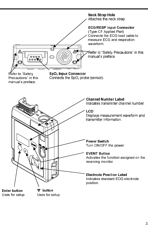
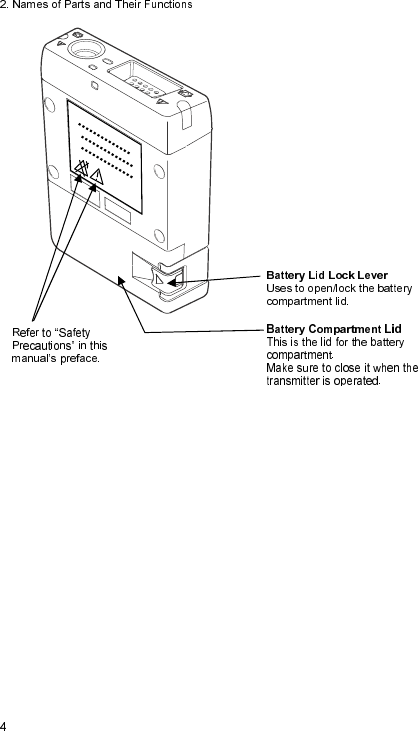
2. Names of Parts and Their Functions
3. Preparation
1) Installing the Batteries
The LX-7230N functions with two "AA" size (“LR06” size) alkaline batteries.
With new batteries, the LX-7230N is capable of the following operation.
LX-7230N: approximately 2.5 days
(However, continuous operating time may be shorter than the above
mentioned time depending on the application of the SpO probe (sensor).)
WARNI N G
Unplug the ECG lead cable when the battery compartment lid is
opened. Otherwise, patient leakage current beyond the allowable value
may occur.
Use new "AA" size (“LR06” size) alkaline batteries.
Do not short out the (+) and (-) terminals. It may result in exothermic
heat and fire, the leakage from the batteries may damage the
equipment, or an explosion from the batteries may occur.
Install the batteries with the correct polarity.
Do not use a disassembled or a damaged battery due to drop or shock.
The leakage from the batteries may damage the equipment, or an
explosion from the batteries may occur.
Do not use different types of batteries at the same time. The leakage
from the batteries may damage the equipment, or an explosion from the
batteries may occur.
Remove the exhausted batteries immediately. The leakage from the
batteries may damage the equipment, or an explosion from the batteries
may occur.
If the transmitter is not in use for a long period of time, remove the
batteries and store the equipment in an appropriate place. If the
batteries are left in the transmitter for a long period of time, the leakage
from the batteries may damage the equipment or an explosion from the
batteries may occur.
Make sure to replace the two batteries simultaneously. If new and used
batteries are mixed, a leakage from the batteries may damage the
equipment or an explosion from the batteries may occur.
CAUTI O N
Use only alkaline batteries. Other batteries will shorten the continuous
operating time.
Once the power switch is on the OFF position, then open the battery
compartment lid.
Do not replace the batteries with wet hands.
In case of storing the used or unused batteries, make sure that the
terminals are not touching other batteries or metal parts.
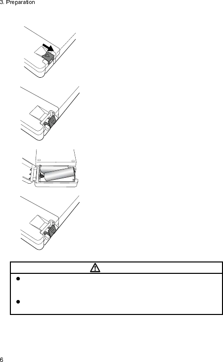
Lift the lock lever to open the battery
compartment lid as shown in the left picture.
Install new batteries according to the polarity
indication inside the battery compartment.
Make sure to first Insert the battery into the
battery compartment from the minus (-)
terminal as shown in the left picture.
Hook the lock lever on the projection from
the body and press it down until it is
horizontal (flat position).
CAUTI O N
Make sure that any foreign particles, such as hairs, are not held on
the battery compartment lid and dust is not adhered to the edge of the
lid to prevent water entering into the battery compartment area.
Make sure to only turn ON the LX-7230N after closing the battery
compartment lid.
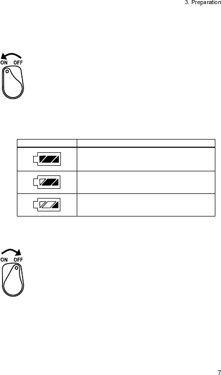
2) Operating Power Switch
Turning the power switch to “ON”
Rotate the power switch to the left until it clicks.
LCD screen turns ON and measurement starts.
Regarding the LCD screen, refer to page 35 (7. Measurement).
The screen automatically turns itself OFF after 180 seconds.
After the power is turned ON, make sure to check the remaining battery level
on the LCD screen.
Refer to the following symbol about the remaining battery level.
Battery Symbol Remaining Battery Level
Full
Getting low but still available
Nearly empty;
Replace the battery
The battery level estimation is in case of using alkaline batteries.
Turning the power switch to “OFF”
Rotate the power switch to the right until it clicks.

Blank Page
4. ECG Monitoring
When the transmitter is used without the SpO probe (sensor), it will measure
only ECG and respiration.
CAUTI O N
When using the transmitter with only the ECG lead cable, SpO
measurements on the receiving monitor shall be turned off to prevent an
erroneous alarm.
Connecting the ECG Lead Cable and Electrodes
The optional ECG lead cables for LX-7230N are as follows.
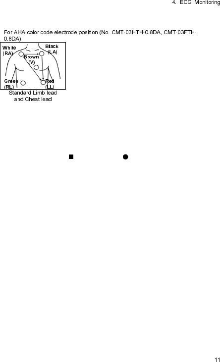
ECG Lead Cables
AHA color code:
Item No. Applicable Lead
Remark
CMT-01HTH-0.8DA
Limb Lead (1CH) 3-electrode Hook Type
(White, Black, Red)
CMT-02HTH-0.8DA
Limb Lead (2CH) 4-electrode Hook Type
(White, Black, Red, Green)
CMT-03HTH-0.8DA
Limb Lead (1CH)
+Chest (1CH)
5-electrode Hook Type
(White, Black, Red, Green, Brown)
CMT-01FTH-0.8DA Limb Lead (1CH) 3-electrode Clip Type
(White, Black, Red)
CMT-02FTH-0.8DA Limb Lead (2CH) 4-electrode Clip Type
(White, Black, Red, Green)
CMT-03FTH-0.8DA Limb Lead (1CH)
+Chest (1CH)
5-electrode Clip Type
(White, Black, Red, Green, Brown)
WARNI N G
Use only the specified lead cable from Fukuda Denshi. Otherwise, proper
monitoring may not be performed, and also it may fail defibrillation or cause
a malfunction of the equipment when the equipment is used with a
defibrillator.
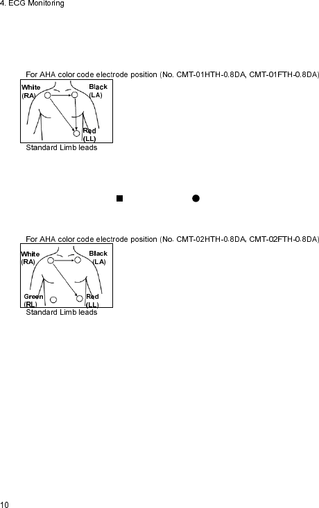
The relations between the attached electrode positions and lead method are
as follows. Attach the electrodes to monitor proper waveform.
For
3
-
electrode lead cable
Standard Limb leads can be selected from lead I, lead II, or lead III under
the setting of the equipment.
Refer to “8. Operation Changing Setup ECG Display Screen (1)
<<Switching Lead>>” in page 47.
For
4
-
electrode lead cable
Two leads measurements, lead I and II are fixed. Lead III, aVR, aVL, and
aVF can be also displayed from the setting on the receiving monitor. For
details, refer to the operation manual of the receiving monitor.
For
5
-
electrode (Chest) lead cable
One limb lead and one chest lead (Brown) measurements are available.
Standard Limb leads can be selected from lead I, lead II, or lead III
under the setting of the equipment.
The chest lead waveform is measured from the chest lead (Brown)
positioned on the chest.
Refer to “8. Operation Changing Setup ECG Display Screen (1)
<<Switching Lead>>” in page 47.
Attaching the Electrodes
CAUTI O N
Always use the same type of electrodes. If different types of
electrodes are used at the same time, the difference between
the polarization potential from each electrode may interfere with
monitoring.
Do not reuse the disposable electrodes. It is intended for single
patient use only.
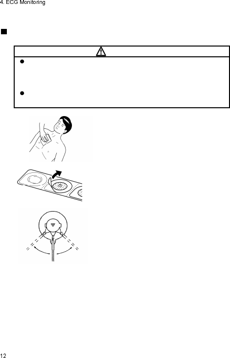
Clean the electrode sites with alcohol wipes
or other skin preparation. If necessary, shave
the electrode sites to remove excessive hair.
Peel off the disposable electrode.
Pay attention not to touch the electrode gel.
Attach the lead cable end to the electrode
(convex part).
Turn right and l
eft to verify that it is securely
attached.
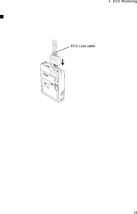
Connecting the ECG Lead Cable to the LX-7230N
Insert the ECG lead cable firmly into the ECG/RESP input connector matching
the transmitter’s connector guide and the direction of the notched part on the
connector.
CAUTI O N
There are some cases when pacemaker pulse cannot be detected
depending on the pacemaker type, pulse voltage, pulse width, electrode
lead type (unipolar, bipolar), electrode placement, or lead method which
causes the pacemaker pulse amplitude to decrease and disables
pacemaker pulse detection.
If signals similar to a pacemaker pulse are present, such as electric
blanket noise or excessive AC frequency noise, these may be
erroneously detected and displayed as a pacemaker pulse. In this case,
check the condition of the electrodes and ECG lead cable to resolve the
cause or turn off the pacemaker detection setting on the receiving
monitor.
Time constant of this equipment is shorter than Fukuda Denshi
monitors (direct ECG connection). Therefore, there is a difference in the
ST measurement value between them. Pay attention to the difference
when monitoring a patient from a transmitter or a monitor.
When an electrode is attached on the same location for a long time,
some patients may develop skin irritation. Check the patient’s skin
condition periodically and change the electrode position as required.
The indication for continuous use of an electrode is about one day.
Replace the electrode if the skin contact gets loosen due to perspiring,
etc.
Make sure to use new disposable electrodes. Otherwise, the waveform
quality may become poor and it may fail to perform correct monitoring.
When “Check Electrode” message is displayed on the screen of the
receiving monitor or the LCD of this equipment, check the condition of
the electrodes and ECG lead cable to resolve the cause.
When removing electrodes from the patient, remove them carefully and
slowly. Do not apply excessive force to remove them. Otherwise, it may
damage the skin.
It may not perform a correct measurement due to the attached position
of the electrodes. Attach the electrodes on the patient referring to page
10 and 11 and make sure that the correct waveform is measured on the
LCD.
5. Respiration Monitoring
Follow the preparation of “4.ECG Monitoring” to allow the respiration
monitoring.
This respiration monitoring is performed with impedance method.
The ECG electrodes are also used for detecting the respiration. Each lead
cable specifies the electrodes to detect the respiration. For 3-electrode and 5-
electrode (chest) lead cable, the electrodes to detect the respiration are fixed
as follows. Even if lead method is switched, they are no changes.
Lead Cable Color of Electrode
3-electrode White (RA) and Red (LL)
4-electrode White (RA) and Red (LL)
5-electrode (Chest) White (RA) and Red (LL)
WARNI N G
Minute ventilation rate-adaptive implantable pacemakers can occasionally
interact with certain cardiac monitoring and diagnostic equipment, causing
the pacemakers to pace at their maximum programmed rate. The cardiac
monitoring and diagnostic equipment may possibly send wrong
information.
If such event occurs, please disconnect the cardiac monitoring and
diagnostic equipment, or follow the procedures described in the operation
manual of the pacemaker.
(For more details, contact FUKUDA DENSHI personnel, your institution’s
professionals, or your pacemaker distributors.)
CAUTI O N
Even if the electrodes are attached on the proper positions for ECG
monitoring, it may not be always the proper ones for respiration
monitoring as well.
When a defibrillator is used during respiration monitoring, a large offset
voltage will be placed on the ECG electrodes, which may cause
interruption of monitoring for a few seconds.
Blank Page
6. SpO
2
Monitoring
When the transmitter is used without the ECG lead cable, it will measure only
SpO .
WARNI N G
When the SpO probe (sensor) is in a connector-off condition, the SpO
alarm will not be generated on the receiving monitor. Make sure that the
SpO probe (sensor) is securely connected. If the SpO waveform/numeric
data is not displayed, check the patient’s condition and pay attention not to
miss the connector-off condition.
CAUTI O N
When using the transmitter with only the SpO sensor cable, ECG and
respiration measurements on the receiving monitor shall be turned off to
prevent an erroneous alarm.
The pulse wave and level meter are normalized for SpO measurement.
It does not indicate perfused blood volume. Check proper probe
attachment by observing the pulse wave.
SpO Monitoring
LX-7230N, which has a built-in Nellcor SpO module, is described in this
section.
The optional SpO sensors available for LX-7230N are as follows.
The following table shows applicable patient and proper site for each SpO
sensor. Select the proper one depending on the purpose and intended use.
Sensor Types Applicable Patient Applied Site
OxiMax MAX-I Infant
(weight of 3 to 20Kg) Toe
OxiMax MAX-P Pediatric
(weight of 10 to 50Kg) Finger
OxiMax MAX-A/AL Adult
(weight of 30Kg and over) Finger
Durasensor DS-100A Adult
(weight of 40Kg and over) Finger
OxiMax MAX-R Adult
(weight of 50Kg and over) Nose
OxiMax MAX-FAST Adult/Pediatric
(weight of 10Kg and over) Forehead
OxiMax MAX-N
Adult
(weight of 40Kg and over) Finger
Neonate
(weight of less 3Kg) Foot
WARNI N G
For SpO monitoring, always use the sensor specified by Fukuda
Denshi. If any other sensor is used, high temperature rise of the sensor
may place the patient in danger of burns in the worst case.
As with all medical equipment, carefully route cables to reduce the
possibility of patient entanglement and strangulation.
CAUTI O N
SpO sensors are not waterproof. Keep away from liquids.
Do not pick up the equipment pulling the sensor or cable part. It may get
disconnected from the equipment and the equipment may be dropped.
A message is displayed when the SpO sensor is disconnected from the
equipment.
A message is displayed when the equipment detects that the SpO
sensor is disconnected from the patient. Properly attach the SpO
sensor to the patient.
Do not reuse the single-use SpO sensor. It may cause incorrect
measurements.
Read through the instruction of the SpO sensor as well.
CAUTI O N
The accuracy of SpO measurement may be influenced by abnormal
hemoglobin, such as carbon monoxide hemoglobin (COHb) and
methemoglobin (MetHb). It may be also affected by cardiogreen or
intravascular dyes.
In addition, the following case may affect the accuracy of SpO and pulse
rate measurement.
Outside light (direct sunlight, fluorescent, light therapy equipment,
surgical light, infrared heat ramp, etc.)
Hypoperfusion
Excessive body motion (patient’s motion)
Pigment injected to the blood for testing
In case of measurement during receiving CPR treatment
Placement of SpO sensor on limb with a blood-pressure cuff, arterial
catheter
External colorant such as nail polish
Abnormally low or high hemoglobin concentration
Venous pulse
Electrosurgery
Influence of electromagnetic waves from other electronics
High-intensity radio waves from mobile phones
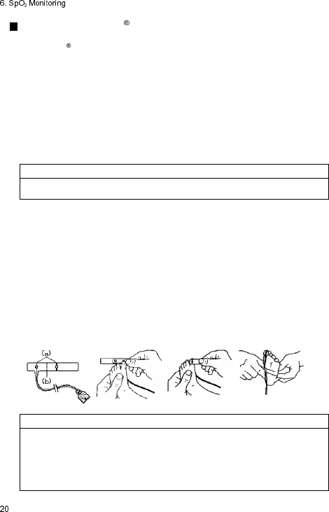
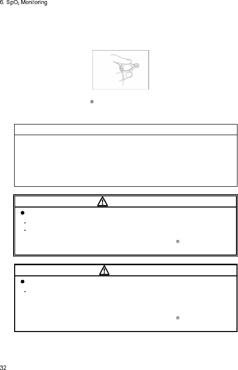
Applying the OxiMax MAX-I sensor
This Nellcor adhesive sensor, model MAX-I, is indicated for continuous
noninvasive arterial oxygen saturation and pulse rate monitoring and can be
reused on the same patient as long as the adhesive tape attaches without
slippage.
1. Remove the plastic backing from the MAX-I and locate the two transparent
windows on the adhesive side. Windows cover optical components. Note
the corresponding alignment marks (a) on the non-adhesive side and the
dashed line (b) midway between the marks (Figure (1)).
The big toe is the preferred MAX-I location. Alternatively, apply the sensor
to another digit of similar size, for example, the thumb.
NOTE
When selecting the sensor site, priority should be given to an extremity free
of an arterial catheter, blood pressure cuff, or intravascular infusion line.
2. Orient the MAX-I so that the window next to the cable is aligned on the
bottom of the big toe as shown. The cable should extend towards the heel
(Figure (2)).
3. Wrap the MAX-I firmly, but not too tightly around the toe. Windows must
oppose each other for correct measurement (Figure (3)).
4. Wrap any excess tape loosely around the toe. Use additional tape
provided to secure the cable across the bottom of the foot, loosely enough
to maintain good circulation (Figure (4)).
5. Connect the MAX-I into the LX-7230N. Verify proper operation as
described in the operation manual.
(1)
(2)
(3)
(4)
NOTE
If the sensor does not track the pulse reliably, it may be incorrectly
positioned – or the sensor site may be too thick, thin, or deeply pigmented,
or otherwise deeply colored (for example, as a result of externally applied
coloring such as nail polish, dye, or pigmented cream) to permit appropriate
light transmission. If any of these situations occurs, reposition the sensor or
choose an alternate Nellcor sensor to use on a different site.
Reapplication
1. The MAX-I can be reused on the same patient as long as the adhesive
tape attaches without slippage.
2. Enclosed adhesive “dots” are provided for reapplication. Place a
transparent dot over each window as shown, and then remove the
protective paper that covers each dot (Figure (5)). The sensor is now ready
to be reapplied to the same patient. For the reapplication, do not remove
the previous adhesive dot, but place the enclosed adhesive dot over it.
CAUTI O N
Precautions for Use of adhesive sensor, MAX-I
Do not reuse the sensor on other patients. This is a sterilized product and it
is intended for single patient use only.
Circulation distal on the sensor site should be checked routinely. The site
must be inspected every 8 hours to ensure adhesion, skin integrity, and
correct optical alignment. If skin integrity changes, move the sensor to
another site
Do not use the sensor on patients who exhibit allergic reactions to the
adhesive tape.
Failure to apply the sensor properly may cause incorrect measurements.
While the sensor is designed to reduce the effects of ambient light,
excessive light may cause inaccurate measurements. In such cases, cover
the sensor with an opaque material.
If the sensor is wrapped too tightly or supplemental tape is applied, venous
pulsations may lead to inaccurate saturation measurements.
Excessive motion may compromise performance. In such cases, try to keep
the patient still, or change the sensor site to one with less motion.
Intravascular dyes or externally applied coloring such as nail polish, dye, or
pigmented cream may lead to inaccurate measurements.
Do not pull the sensor cable to remove the sensor from the equipment.
In the event of damage to the sterile packaging, do NOT use. Make sure to
check whether the packaging and product is cracked or damaged before
use. If there is any damage.
Do not immerse in water or cleaning solutions. Do not resterilize.
For additional warnings, cautions or contraindications when using sensors
with the LX-7230N, refer to each Nellcor SpO sensor instruction manual.
(5)
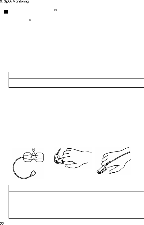
Applying the OxiMax MAX-P/ MAX-A/ MAX-AL sensor
This Nellcor adhesive sensor, model MAX-P/ MAX-A/ MAX-AL, is indicated
for continuous noninvasive arterial oxygen saturation and pulse rate monitoring
and can be reused on the same patient as long as the adhesive tape attaches
without slippage.
1. Remove the plastic backing from the MAX-P/MAX-A/MAX-AL and locate
the transparent windows (a) on the adhesive side. Windows cover optical
components (Figure (1)).
The index finger is the preferred MAX-P/MAX-A/MAX-AL location.
Alternatively, apply the sensor to the small thumb, smaller finger, or big toe.
NOTE
When selecting the sensor site, priority should be given to an extremity free
of an arterial catheter, blood pressure cuff, or intravascular infusion line.
2. Orient the MAX-P/MAX-A/MAX-AL so that the dashed line in the middle of
the sensor is centered on the tip of the finger/toe (Figure (2)). Wrap the
adhesive flaps around the digit. Note that the cable must be positioned on
the top of the hand or foot.
3. Fold the cable end over the top of the finger/toe so that the windows are
directly opposite to each other. Wrap the adhesive securely around both
sides of the digit (Figure (3)).
4. Connect the MAX-P/MAX-A/MAX-AL into the LX-7230N. Verify proper
operation as described in the operation manual.
(1)
(2)
(3)
NOTE
If the sensor does not track the pulse reliably, it may be incorrectly
positioned – or the sensor site may be too thick, thin, or deeply pigmented,
or otherwise deeply colored (for example, as a result of externally applied
coloring such as nail polish, dye, or pigmented cream) to permit appropriate
light transmission. If any of these situations occurs, reposition the sensor or
choose an alternate Nellcor sensor to use on a different site.
CAUTI O N
Precautions for Use of adhesive sensors, MAX-P/MAX-A/MAX-AL
Do not reuse the sensor on other patients. This is a sterilized product and it
is intended for single patient use only.
Circulation distal on the sensor site should be checked routinely. The site
must be inspected every 8 hours to ensure adhesion, skin integrity, and
correct optical alignment. If skin integrity changes, move the sensor to
another site
Do not use the sensor on patients who exhibit allergic reactions to the
adhesive tape.
Failure to apply the sensor properly may cause incorrect measurements.
While the sensor is designed to reduce the effects of ambient light,
excessive light may cause inaccurate measurements. In such cases, cover
the sensor with an opaque material.
If the sensor is wrapped too tightly or supplemental tape is applied, venous
pulsations may lead to inaccurate saturation measurements.
Excessive motion may compromise performance. In such cases, try to keep
the patient still, or change the sensor site to one with less motion.
Intravascular dyes or externally applied coloring such as nail polish, dye, or
pigmented cream may lead to inaccurate measurements.
Do not pull the sensor cable to remove the sensor from the equipment.
In the event of damage to the sterile packaging, do NOT use. Make sure to
check whether the packaging and product is cracked or damaged before
use. If there is any damage.
Do not immerse in water or cleaning solutions. Do not resterilize.
For additional warnings, cautions or contraindications when using sensors
with the LX-7230N, refer to each Nellcor SpO sensor instruction manual.
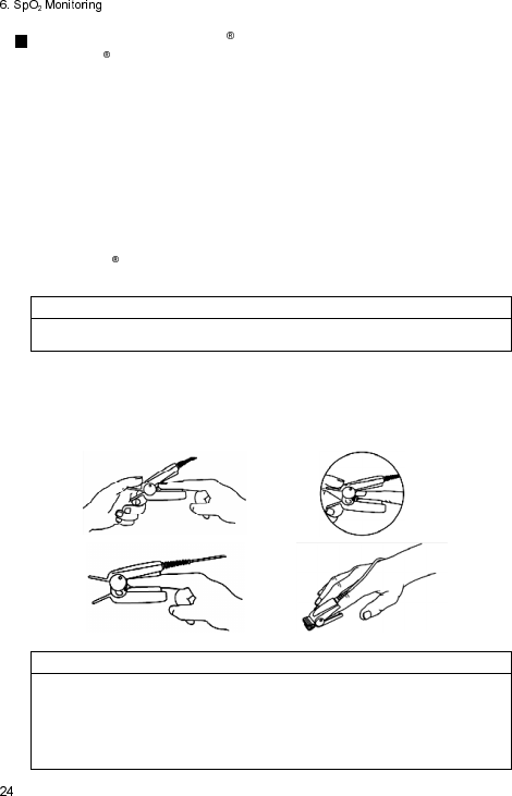
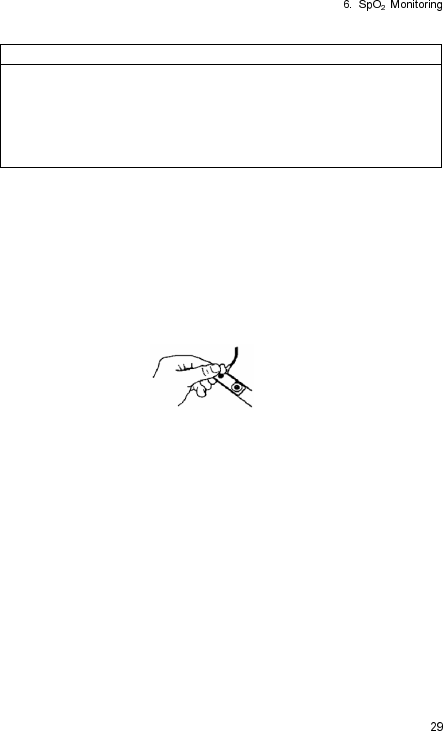
Applying DURASENSOR DS-100A
This Nellcor reusable sensor, model DS-100A, is indicated for continuous
noninvasive arterial oxygen saturation and pulse rate monitoring for patients
weighing greater than 40 kg. The DS-100A is contraindicated for use on active
patients or for prolonged use.
1. Place the index finger over the sensor window of the DS-100A with the
finger tip against the stop (Figure (1)).
2. If the fingernail is long, the nail tip will extend over the finger stop (Figure
(2)).
3. Spread open the rear tabs of the sensor to provide even force over the
length of the pads (Figure (3)). If the index finger cannot be positioned
correctly, or is not available, a smaller finger can be used, or use other
OxiMax sensor. Do not use the DS-100A on a thumb or toe or across a
child’s hand or foot.
NOTE
When selecting the sensor site, priority should be given to an extremity free
of an arterial catheter, blood pressure cuff, or intravascular infusion line.
4. The sensor should be oriented in such a way that the cable is positioned
along the top of the hand (Figure (4)).
5. Connect the DS-100A into the LX-7230N. Verify proper operation as
described in the operation manual.
(1)
(2)
(3)
(4)
NOTE
If the sensor does not track the pulse reliably, it may be incorrectly
positioned – or the sensor site may be too thick, thin, or deeply pigmented,
or otherwise deeply colored (for example, as a result of externally applied
coloring such as nail polish, dye, or pigmented cream) to permit appropriate
light transmission. If any of these situations occurs, reposition the sensor or
choose an alternate Nellcor sensor to use on a different site.
CAUTI O N
Precautions for Use of reusable sensors, DS-100A
Do not apply the sensor on the thumb or toe. It may cause incorrect
measurements.
Do not use the sensor for long-term monitoring.
Circulation distal on the sensor site should be checked routinely. Reusable
sensors must be moved to a new site at least every 4 hours. Because
individual skin condition affects the ability of the skin to tolerate sensor
placement, it may be necessary to change the sensor site more frequently
with some patients. If skin integrity changes, move the sensor to another
site. If long-term monitoring is required, use an OxiMax sensor (MAX-A,
MAX-AL, or MAX-N).
Failure to apply the sensor properly may cause incorrect measurements.
While the sensor is designed to reduce the effects of ambient light,
excessive light may cause inaccurate measurements. In such cases, cover
the sensor with an opaque material.
Excessive motion may compromise performance. In such cases, try to keep
the patient still, or change the sensor site to one with less motion.
Intravascular dyes or externally applied coloring such as nail polish, dye, or
pigmented cream may lead to inaccurate measurements.
Do not pull the sensor cable to remove the sensor from the equipment.
In the event of damage to the sterile packaging, do NOT use. Make sure to
check whether the packaging and product is cracked or damaged before
use. If there is any damage.
Do not immerse in water or cleaning solutions. Do not resterilize.
For additional warnings, cautions or contraindications when using sensors
with the LX-7230N, refer to each Nellcor SpO sensor instruction manual.
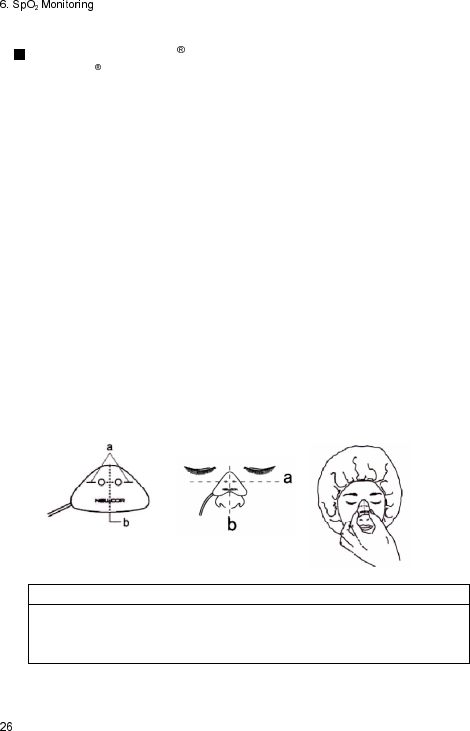
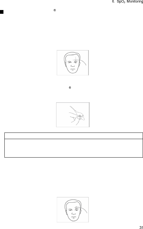
Applying the OxiMax MAX-R sensor
This Nellcor adhesive sensor, model MAX-R, is indicated for continuous
noninvasive arterial oxygen saturation and pulse rate monitoring. The MAX-R
is designed for use only on the nose. Use this sensor when finger pulsatile flow
is inadequate, or monitoring a finger/toe is not possible.
1. Clean the bridge of the patient’s nose with the contents of the enclosed
acetone/alcohol ampule to remove skin oils. Do not allow the
acetone/alcohol solution to get in the patient’s eyes.
2. Remove the plastic backing from the MAX-R and locate the transparent
windows on the adhesive side. Windows cover optical components. Note
the corresponding alignment marks on the non-adhesive side (a) and the
dashed center line (b) midway between the marks (Figure (1)).
3. Orient the MAX-R so that the dashed line is centered on the nose (a) and
the alignment marks are at the bone-cartilage junction (b). The cable
should extend toward the patient’s right side (Figure (2)).
4. Press the MAX-R firmly onto the nose and hold in place for 10 seconds to
ensure adhesion (Figure (3)). The MAX-R must be secured firmly for
proper operation.
5. As with all medical equipment, carefully route cables to reduce the
possibility of patient entanglement or strangulation.
6. Connect the MAX-R into the LX-7230N. Verify proper operation as
described in the operation manual.
(1)
(2)
(3)
NOTE
If the sensor does not track the pulse reliably, it may be incorrectly
positioned – or the sensor site may be too thick, thin, or deeply pigmented
to permit appropriate light transmission. If any of these situations occurs, try
another MAX-R or choose an alternate Nellcor Puritan Bennett sensor.
CAUTI O N
Precautions for Use of adhe
sive sensor, MAX-R
Do not reuse the sensor on other patients. This is a sterilized product and it
is intended for single patient use only.
Circulation distal on the sensor site should be checked routinely. The site
must be inspected every 8 hours to ensure adhesion, skin integrity, and
correct sensor site. If skin integrity changes, move the sensor to another site
Do not use the sensor on patients who exhibit allergic reactions to the
adhesive tape.
Do not get the acetone/alcohol cleaning solution in the patient’s eyes.
Failure to apply the sensor properly may cause incorrect measurements.
While the sensor is designed to reduce the effects of ambient light,
excessive light may cause inaccurate measurements. In such cases, cover
the sensor with an opaque material.
Intravascular dyes or externally applied coloring such as dye or pigmented
cream may lead to inaccurate measurements.
Take care when removing the MAX-R so that the adhesive does not
damage delicate facial tissue.
The MAX-R is not recommended for patients wearing oxygen or anesthesia
masks.
Excessive motion may compromise performance.
Do not pull the sensor cable to remove the sensor from the equipment.
In the event of damage to the sterile packaging, do NOT use. Make sure to
check whether the packaging and product is cracked or damaged before
use. If there is any damage.
Do not immerse in water or cleaning solutions. Do not resterilize.
For additional warnings, cautions or contraindications when using sensors
with the LX-7230N, refer to each Nellcor SpO sensor instruction manual.

Applying the OxiMax MAX-N sensor
This Nellcor adhesive sensor, model MAX-N, is indicated for continuous
noninvasive arterial oxygen saturation and pulse rate monitoring and can be
reused on the same patient as long as the adhesive tape attaches without
slippage.
1. Remove the plastic backing from the MAX-N and locate the two
transparent windows on the adhesive side. Windows cover optical
components. Note the corresponding alignment marks (a) on the non-
adhesive side and the dashed line (b) midway between the marks (Figure
(1)).
2. Orient the MAX-N so that the dashed line is on the lateral edge of the site
(a):
Neonates: The preferred site is the foot. Alternatively, use the hand. The
window next to the cable goes on the sole of the foot as shown (Figure (2)).
Adults: The preferred site is the index finger. Alternatively, other fingers
may be used. The window next to the cable goes on the nail side, distal to
the first joint. Do not place on a joint. Note that the cable must be
positioned on the top of the hand (Figure (3)).
NOTE
When selecting a sensor site, priority should be given to an extremity free of
an arterial catheter, blood pressure cuff, or intravascular infusion line.
3. Wrap the MAX-N firmly, but not too tightly around the foot or finger.
Windows must oppose each other.
4. Connect the MAX-N into the LX-7230N. Verify proper operation as
described in the operation manual.
(1)
(2)
(3)
NOTE
If the sensor does not track the pulse reliably, it may be incorrectly
positioned - or the sensor site may be excessively wrinkled, or too deeply
pigmented or otherwise deeply colored (for example, as a result of
externally applied coloring such as dye or pigmented cream) to permit
appropriate light transmission. If any of these situations occurs, reposition
the sensor in a different location or choose an alternate Nellcor sensor to
use on a different site.
Reapplication
1. The MAX-A can be reused on the same patient as long as the adhesive
tape attaches without slippage.
2. Enclosed adhesive “dots” are provided for reapplication. Place the
transparent dot over each window as shown, and then remove the
protective paper that covers each dot (Figure (4)). The sensor is now
ready to be reapplied to the same patient. For the reapplication, do not
remove the previous adhesive dot, but place the enclosed adhesive dot
over it.
(4)
CAUTI O N
Precautions for Use of adhesive sensor, MAX-N
Do not reuse the sensor on other patients. This is a sterilized product and it
is intended for single patient use only.
Circulation distal on the sensor site should be checked routinely. The site
must be inspected every 8 hours to ensure adhesion, skin integrity, and
correct optical alignment. If skin integrity changes, move the sensor to
another site.
Do not use the sensor on patients who exhibit allergic reactions to the
adhesive tape.
Failure to apply the sensor properly may cause incorrect measurements.
While the sensor is designed to reduce the effects of ambient light,
excessive light may cause inaccurate measurements. In such cases, cover
the sensor with an opaque material.
If the sensor is wrapped too tightly or supplemental tape is applied, venous
pulsations may lead to inaccurate saturation measurements.
Excessive motion may compromise performance. In such cases, try to keep
the patient still, or change the sensor site to one with less motion.
Intravascular dyes or externally applied coloring such as nail polish, dye, or
pigmented cream may lead to inaccurate measurements.
Do not pull the sensor cable to remove the sensor from the equipment.
In the event of damage to the sterile packaging, do NOT use. Make sure to
check whether the packaging and product is cracked or damaged before
use. If there is any damage.
Do not immerse in water or cleaning solutions. Do not resterilize.
For additional warnings, cautions or contraindications when using sensors
with the LX-7230N, refer to each Nellcor SpO sensor instruction manual.
Applying the OXIMAX MAX-FAST sensor
This is an adhesive sensor, model MAX-FAST, for continuous noninvasive
arterial oxygen saturation and pulse rate monitoring and can be reused on the
same patient as long as the adhesive tape attaches without slippage.
1. Clean the sensor site with an alcohol wipe to remove skin oils. See
illustration for the recommended site. (Figure (1))
(1)
2. Remove the white paper backing to expose the first of three adhesive
pads (Figure (2)). The OXIMAX MAX-FAST sensor is now ready to be
applied on the patient.
(2)
NOTE
There are three adhesive pads attached to the sensor, each with a pull-tab
for removal. When repositioning the sensor on the same patient, first
expose the new adhesive pad by grasping the tab and peeling off the old
adhesive pad. The sensor is now ready to be reapplied to the patient.
3. Place the sensor onto a flat, hairless portion of the patient’s forehead just
above the left or right eyebrow. If the patient is lying on their side, place
the sensor above the eye on the side of the patient’s head not in contact
with the bed. Press the MAX-FAST sensor firmly in place for 10 seconds,
ensuring that the entire surface area of the adhesive pad makes contact
with the skin (Figure (3)).
(3)
4. If desired, the sensor cable can be secured to the patient’s clothing or
other material by using the clip located on the cable. To open, pinch the
sides of the clip; release to close (Figure (4)).
(4)
5. Connect the OXIMAX MAX-FAST oximetry sensor into the LX-7230N.
Verify proper operation as described in the operation manual.
NOTE
If the sensor does not track the pulse reliably, it may be incorrectly
positioned - or the sensor site may be excessively wrinkled, or too deeply
pigmented or otherwise deeply colored (for example, as a result of
externally applied coloring such as dye or pigmented cream) to permit
appropriate light transmission. If any of these situations occurs, reposition
the sensor in a different location or choose an alternate Nellcor sensor to
use on a different site.
WARNI N G
Precautions for Use of headband
Do not use headband on children age 24 months and younger.
Do not use headband on children with open fontanelles.
For details, refer to the instruction manual of OXIMAX MAX-FAST
oximetry sensor.
CAUTI O N
Precautions for Use of headband
Applying the headband too loose or too tight can cause inaccurate
readings. Make sure the headband applies equal pressure to the entire
sensor. The sensor must be completely covered by the headband.
For details, refer to the instruction manual of OXIMAX MAX-FAST
oximetry sensor.
CAUTI O N
Precautions for Use of adhesive sensors, MAX-FAST
Do not reuse the sensor on other patients. This is a sterilized product and it
is intended for single patient use only.
Circulation distal on the sensor site should be checked routinely. The site
must be inspected every 12 hours to ensure adhesion, skin integrity, and
correct position. Because individual skin condition affects the ability of the
skin to tolerate sensor placement, it may be necessary to change the sensor
site more frequently with some patients.
Do not use the OXIMAX MAX-FAST sensor on patients who exhibit allergic
reactions to the adhesive pad; for patients who perspire profusely; or under
conditions where the patient is in the Trendelenburg position (head lower
than the heart).
Failure to apply the sensor properly may cause incorrect measurements.
While the sensor is designed to reduce the effects of ambient light,
excessive light may cause inaccurate measurements. In such cases, cover
the sensor with an opaque material.
Do not use tape with the sensor. Use of additional tape or other types of
adhesives may cause skin damage.
Applying the headband too tightly can lead to inaccurate saturation
measurements, or possibly to temporary pressure marks from sensor.
Excessive motion may compromise performance. In such cases, try to keep
the patient still, or change the sensor site to one with less motion.
For patients in a prone position, venous pooling and/or pulsation may cause
inaccurate SpO readings. Use of the headband is advised.
Do not pull the sensor cable to remove the sensor from the equipment.
In the event of damage to the sterile packaging, do NOT use. Make sure to
check whether the packaging and product is cracked or damaged before
use. If there is any damage.
Do not immerse in water or cleaning solutions. Do not resterilize.
For additional warnings, cautions or contraindications when using sensors
with the LX-7230N, refer to each Nellcor SpO sensor and headband
instruction manual.
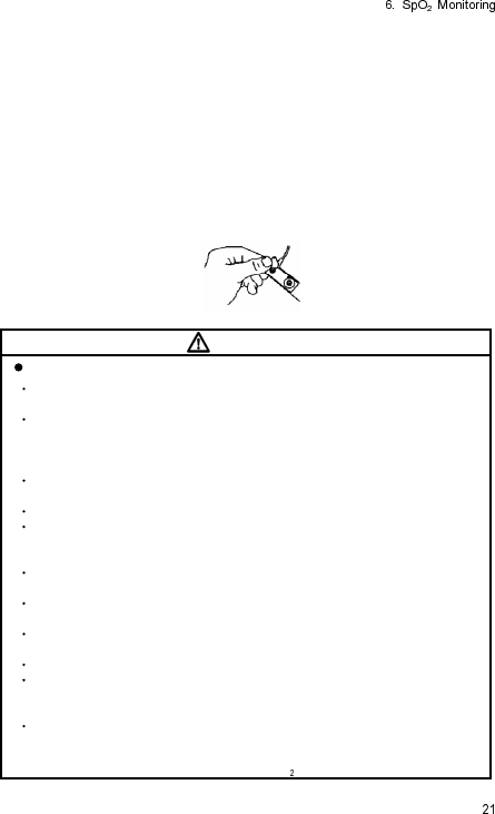
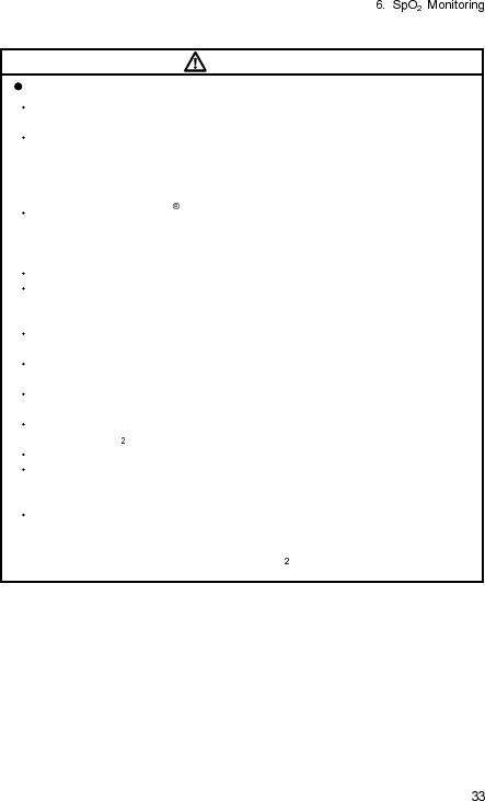
Connecting the Nellcor SpO Sensor to the LX-7230N
1 Insert the SpO sensor into the SpO input connector on the LX-7230N.
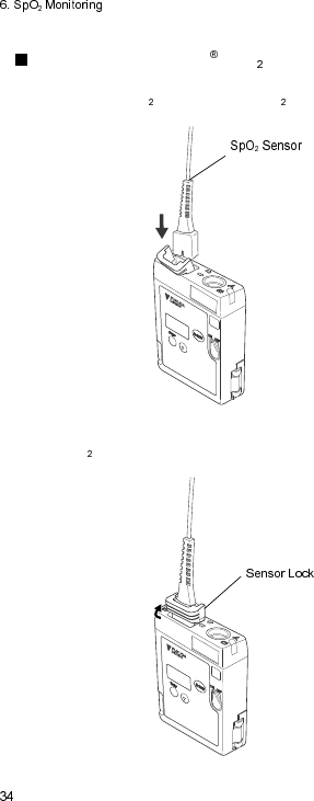
2 Attach the sensor lock as shown in the following illustration to prevent the
SpO sensor to be disconnected.
7. Measurement
Turn ON the power and the measurement starts.
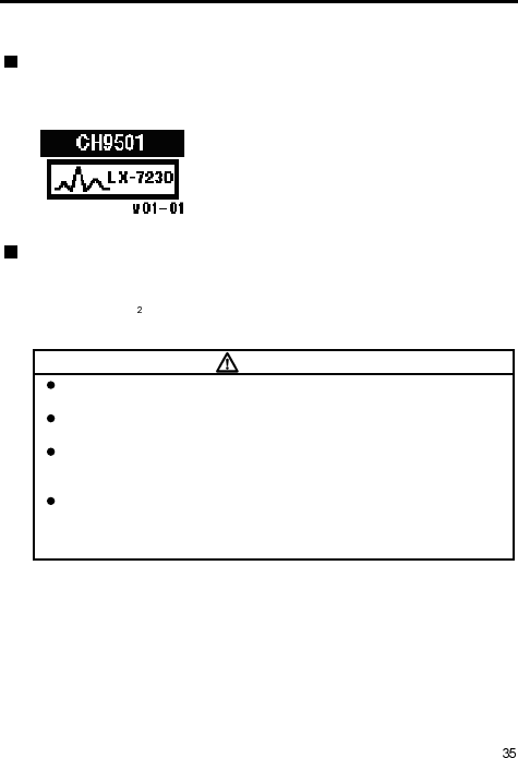
Starting Screen
When the power is turned ON, the channel number configured on the LX-
7230N is displayed at the top of the LCD.
Make sure whether the channel number on the
LCD matches the channel number indicated on
the label of the LX-7230N and the channel
number configured on the receiving monitor.
This screen automatically moves onto the next
waveform display screen.
Waveform Display Screen
ECG waveform (1CH when using 3-electrode lead cable, 2CH when using
other lead cable), heart rate, pacemaker marker, respirogram, respiration rate,
pulse wave, SpO measurement value, remaining battery level, and various
messages are displayed.
CAUTI O N
The LX-7230N does not have a diagnostic function. Check the
diagnostic function on the receiving monitor.
The LX-7230N does not have an alarm function. Check the alarm
function on the receiving monitor.
The ECG waveform size and sweep speed settings displayed on the
LCD of the LX-7230N do not interface with the ones displayed on the
screen of the receiving monitor.
The heart rate and respiration rate displayed on the LCD of the LX-
7230N may be different from the ones displayed on the receiving
monitor. Because the algorithm of the ECG and respiration rate is
different.
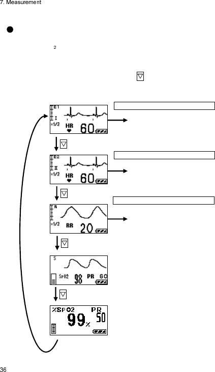
Display Switch
The screen (e.g. ECG) can be switched to other selected screens (respiration,
pulse, or SpO , etc.)
The LCD display will automatically turn itself OFF after 180 seconds if no
operation is done. To restart the LCD display, refer to page 51.
When the LCD display is active, press the button to move onto the next
screen. The screen will be switched in the following order.
Press and hold Enter for 2 seconds
Move onto ECG1 Lead/Waveform
size setting display
Move onto ECG2 waveform size
setting display
Move onto RESP waveform size
setting display
Press and hold Enter for 2 seconds
Press and hold Enter for 2 seconds
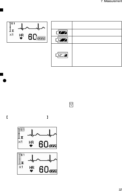
Battery Level Check
Check the battery level on the waveform display screen.
Battery
Symbol Remaining Battery Level
Full
Getting low but still available
Nearly empty
Replace the battery.
A message that prompts the
battery check appears on the
screen of the receiving
monitor.
Waveform Display
ECG Display Screen (1)
ECG1 waveform, heart rate, pacemaker marker, remaining battery level, and
electrode check message are displayed.
The LCD display will automatically turn itself OFF after 180 seconds if no
operation is done. To restart the LCD display, refer to page 51.
When the LCD display is active, press the button to move onto the next
waveform display screen.
Descriptions of the Screen
The descriptions of contents displayed on the LCD are as follows.
Indicates ECG 1.
Indicates the scale of the displayed
ECG.
One scale corresponds to 1mV.
In the left illustration, it can display
ECG waveform between -1mV and
+1mV.
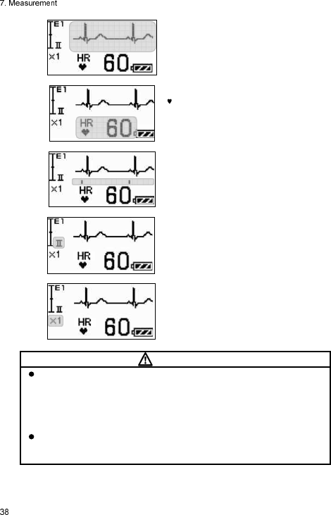
Displays the ECG waveform.
Displays the heart rate.
is displayed in synchronization with
the heart rate.
Displays the detection marker when
the pacemaker pulse is detected.
Indicates the measuring lead.
Indicates the ECG waveform size
displayed on the LCD.
CAUTI O N
The ECG waveform size setting displayed on the LCD does not interact
with the one displayed on the screen of the receiving monitor, because
the LX-7230N cannot transmit the setting information of the waveform
size to the receiving monitor. If the ECG waveform size displayed on the
screen of the receiving monitor is changed, follow the instruction in the
operation manual of the receiving monitor.
In case of the outside of the heart rate range (12 to 300bpm), 0bpm will
be displayed if 11bpm and below is measured and 300bpm will be
displayed If 300bpm and above is measured.
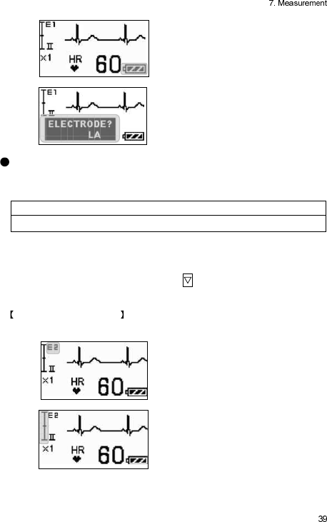
Indicates the remaining battery level.
For details of the battery level, refer to
page 7.
Displays the electrode check
“ELECTRODE?” message appears
when the ECG electrode is detached.
ECG Display Screen (2)
ECG2 waveform, heart rate, pacemaker marker, remaining battery level, and
electrode check message are displayed.
NOTE
If a 3-electrode lead cable is used, this screen will not appear.
The LCD display will automatically turn itself OFF after 180 seconds if no
operation is done. To restart the LCD display, refer to page 51.
When the LCD display is active, press the button to move onto the next
waveform display screen.
Descriptions of the Screen
The descriptions of contents displayed on the LCD are as follows.
Indicates ECG 2.
Indicates the scale of the displayed
ECG.
One scale corresponds to 1mV.
In the left illustration, it can display ECG
waveform between -1mV and +1mV.
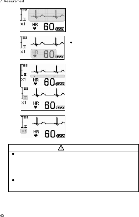
Displays the ECG waveform.
Displays the heart rate.
is displayed in synchronization with
the heart rate.
Displays the detection marker when the
pacemaker pulse is detected.
Indicates the measuring lead.
Indicates the ECG waveform size
displayed on the LCD.
CAUTI O N
The ECG waveform size setting displayed on the LCD of the LX-7230N
does not interact with the one displayed on the screen of the receiving
monitor, because the LX-7230N cannot transmit the setting information
of the waveform size to the receiving monitor. If the ECG waveform size
displayed on the screen of the receiving monitor is changed, follow the
instruction in the operation manual of the receiving monitor.
In case of the outside of the heart rate range (12 to 300bpm), 0bpm will
be displayed if 11bpm and below is measured and 300bpm will be
displayed If 300bpm and above is measured.
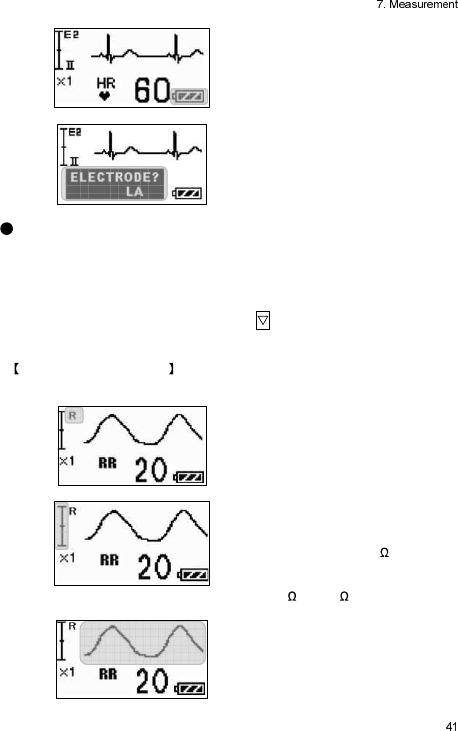
Indicates the remaining battery level.
For details of the battery level, refer to
page 7.
Displays the electrode check
“ELECTRODE?” message appears
when the ECG electrode is detached.
Respiration Display Screen
Respiration waveform, respiration rate, remaining battery level, and electrode
check message are displayed.
The LCD display will automatically turn itself OFF after 180 seconds if no
operation is done. To restart the LCD display, refer to page 51.
When the LCD display is active, press the button to move onto the next
waveform display screen.
Descriptions of the Screen
The descriptions of contents displayed on the LCD are as follows.
Indicates the respiration waveform
display screen.
Indicates the scale of the displayed
respiration waveform.
One scale corresponds to 1 .
In the left illustration, it can display
the change of respiration waveform
between -1 and +1 .
Displays the respiration waveform.
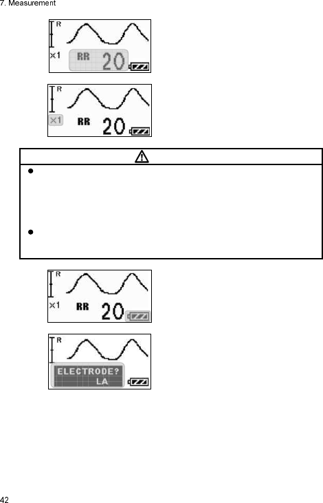
Displays the respiration rate.
Indicates the respiration waveform
size displayed on the LCD.
CAUTI O N
The respiration waveform size setting displayed on the LCD does not
interact with the one displayed on the screen of the receiving monitor,
because the LX-7230N cannot transmit the setting information of the
waveform size to the receiving monitor. If the respiration waveform size
displayed on the screen of the receiving monitor is changed, follow the
instruction in the operation manual of the receiving monitor.
In case of the outside of the respiration rate range (9 to 150Bpm), 0Bpm
will be displayed if 8Bpm and below is measured and 150Bpm will be
displayed If 150Bpm and above is measured.
Indicates the remaining battery level.
For details of the battery level, refer to
page 7.
Displays the electrode check
“ELECTRODE?” message appears
when the ECG electrode is detached.
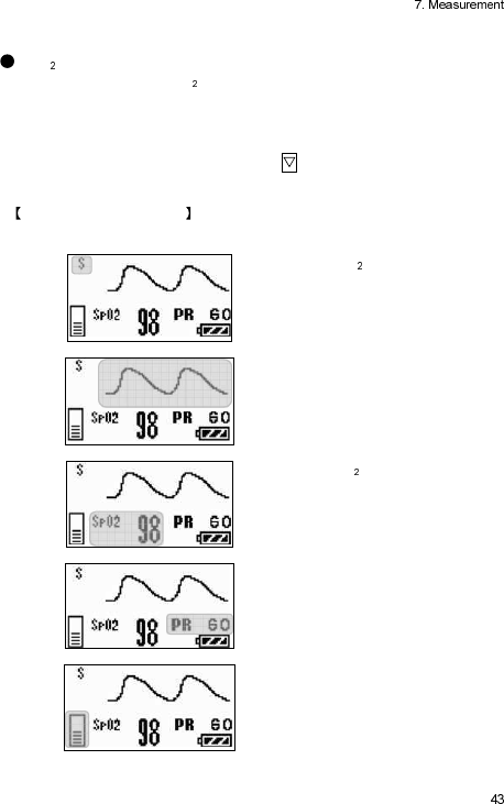
SpO Display Screen
Pulse wave, pulse rate, SpO measurement value, remaining battery level, and
probe condition are displayed.
The LCD display will automatically turn itself OFF after 180 seconds if no
operation is done. To restart the LCD display, refer to page 51.
When the LCD display is active, press the button to move onto the next
waveform display screen.
Descriptions of the Screen
The descriptions of contents displayed on the LCD are as follows.
Indicates the SpO display screen.
Displays the pulse wave.
The waveform size displayed on the
LCD is adjusted automatically.
Displays the SpO measurement value.
Displays the pulse rate.
Displays the level meter of the pulse
wave.
Indicates the amplitude level of the
pulse wave in 8 steps.
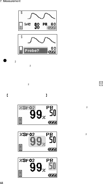
Indicates the remaining battery level.
For details of the battery level, refer to
page 7.
Displays messages such as probe off.
For details of messages, refer to page
60.
SpO Enlarged Display Screen
Pulse rate, SpO measurement value, remaining battery level, and probe
condition are displayed.
The LCD display will automatically turn itself OFF after 180 seconds if no
operation is done. To restart the LCD display, refer to page 51.
When the SpO Enlarged Display Screen is displayed, press the button to
move onto the next waveform display screen.
Descriptions of the Screen
The descriptions of contents displayed on the LCD are as follows.
Indicates the SpO display screen.
Displays the SpO measurement
value.
Displays the pulse rate.
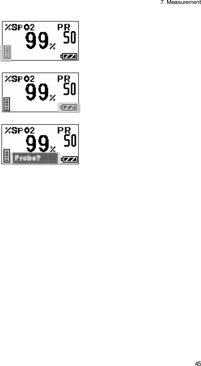
Displays the level meter of the pulse
wave.
Indicate the amplitude level of the
pulse wave in 8 steps.
Indicates the remaining battery level.
For details of the battery level, refer to
page 7.
Displays messages such as probe off.
For details of messages, refer to page
60.
Blank Page
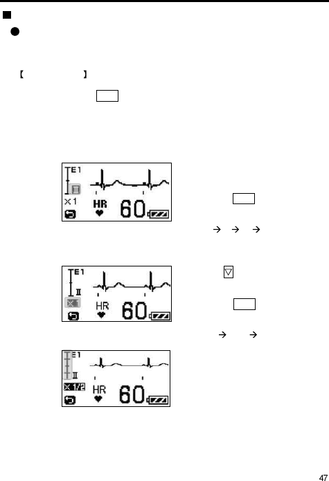
8. Operation
Changing Setup
ECG Display Screen (1)
In the ECG display screen (1), the ECG waveform size and lead displayed on
the LCD of the LX-7230N can be changed.
Setting Method
How to enter the setup mode:
Press and hold the Enter button for 2 seconds in the ECG display screen (1).
<<Switching Lead>>
Lead of ECG 1 can be switched when 3-electrode lead cable or 5-electrode
(Chest) lead cable is used.
Select an appropriate lead by checking the ECG waveform on the LCD.
The lead indication of ECG 1 is
highlighted.
Pressing the Enter button will
sequentially change the lead of
ECG 1.
Lead I II III I
<<Changing ECG1 Waveform Size on LCD>>
Press the button to highlight
the size indication of ECG 1.
Pressing the Enter button will
sequentially change the size of
ECG 1.
Size ×1 ×1/2 ×1
When changing the size of the
ECG waveform on the LCD, the
ECG scale will also change.
In the left illustration, it can
display the ECG waveform
between -2mV and +2mV.
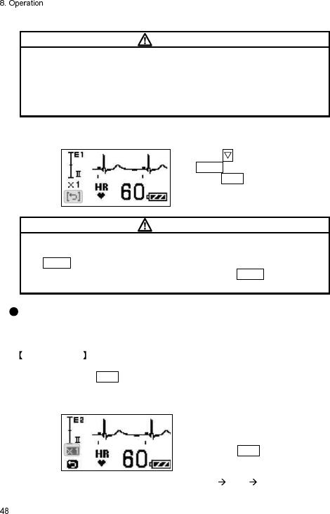
CAUTI O N
The ECG waveform size setting displayed on the LCD of the LX-7230N
does not interact with the one displayed on the screen of the receiving
monitor, because the LX-7230N cannot transmit the setting information of
the waveform size to the receiving monitor. If the ECG waveform size
displayed on the screen of the receiving monitor is changed, follow the
instruction in the operation manual of the receiving monitor.
<< Returning to ECG Display Screen (1) >>
Press the button to highlight
the Return button.
Press the Enter button to return to
the ECG display screen (1).
CAUTI O N
Do not operate the LX-7230N with the setup screen open to prevent the
settings to be changed due to an unintended operation. Make sure to press
the Return button to terminate the setup screen. The LCD display will
automatically turn itself OFF after 180 seconds if the Return button is not
pressed.
ECG Display Screen (2)
In the ECG display screen (2), the ECG waveform size displayed on the LCD
of the LX-7230N can be changed.
Setting Method
How to enter the setup mode:
Press and hold the Enter button for 2 seconds in the ECG display screen (2).
<< Changing ECG2 Waveform Size on LCD >>
The size indication of ECG 2 is
highlighted.
Pressing the Enter button will
sequentially change the size of
ECG 2.
Size ×1 ×1/2 ×1
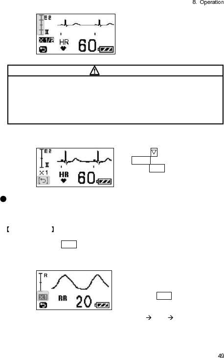
When changing the size of the
ECG waveform on the LCD, the
ECG scale will also change.
In the left illustration, it can
display ECG waveform between
-2mV and +2mV.
CAUTI O N
The ECG waveform size setting displayed on the LCD of the LX-7230N
does not interact with the one displayed on the screen of the receiving
monitor, because the LX-7230N cannot transmit the setting information of
the waveform size to the receiving monitor. If the ECG waveform size
displayed on the screen of the receiving monitor is changed, follow the
instruction in the operation manual of the receiving monitor.
<< Returning to ECG display screen (2) >>
Press the button to highlight
the Return button.
Press the Enter button to return to
the ECG display screen (2).
Respiration Display Screen
In the respiration display screen, the respiration waveform size displayed on
the LCD of the LX-7230N can be changed.
Setting Method
How to enter the setup mode:
Press and hold the Enter button for 2 seconds in the respiration display screen.
<< Changing Respiration Waveform Size on LCD>>>
The size indication of the
respiration is highlighted.
Pressing the Enter button will
sequentially change the size of
respiration.
Size ×1 ×1/2 ×1
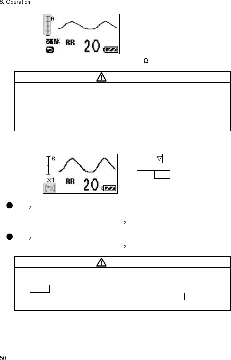
When changing the size of the
respiration waveform on the LCD,
the respiration scale will also
change.
In the left illustration, it can
display the respiration waveform
until 4 of change.
CAUTI O N
The respiration waveform size setting displayed on the LCD of the LX-
7230N does not interact with the one displayed on the screen of the
receiving monitor, because the LX-7230N cannot transmit the setting
information of the waveform size to the receiving monitor. If the respiration
waveform size displayed on the screen of the receiving monitor is changed,
follow the instruction in the operation manual of the receiving monitor.
<< Returning to Respiration Display Screen>>
Press the button to highlight
the Return button.
Press the Enter button to return to
the respiration display screen.
SpO Display Screen
LX-7230N has no setup item in the SpO display screen
SpO Enlarged Display Screen
LX-7230N has no setup item in the SpO display screen
CAUTI O N
Do not operate the LX-7230N with the setup screen open to prevent the
settings to be changed due to an unintended operation. Make sure to press
the Return button to terminate the setup screen. The LCD display will
automatically turn itself OFF after 180 seconds if the Return button is not
pressed.
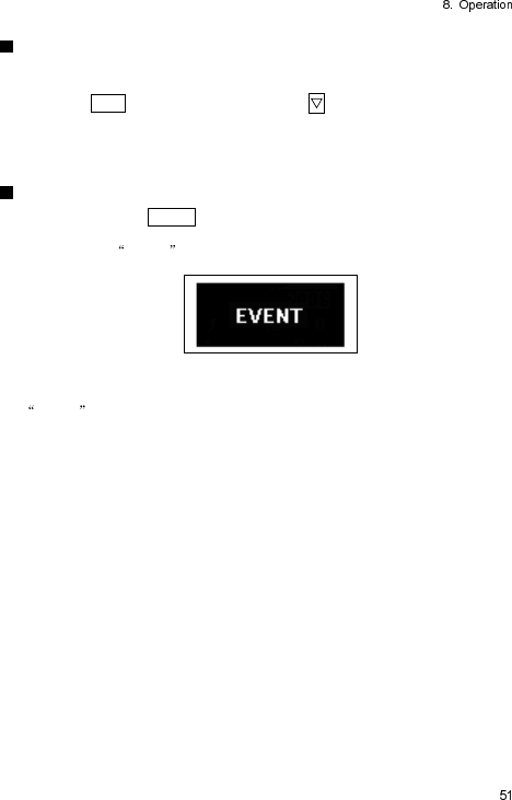
Restarting the LCD display
The LCD display will automatically turn itself OFF after 180 seconds if no
operation is done.
Press the Enter button or press and hold the button to restart the LCD
display.
The starting screen with telemetry channel number appears, and then the
waveform display screen appears.
Pressing the EVENT button
Press and hold the EVENT button for 2 seconds to activate the function
assigned on the receiving monitor. The following message appears on the
LCD while the EVENT is transmitted.
After the transmission is completed, the starting screen with the telemetry
channel number appears, and then the waveform display screen appears.
EVENT operation is available as a remote recording.
For details of the receiving monitor operation and settings related to the
“EVENT” function, refer to the operation manual of the receiving monitor.

Blank Page

9. Other Setting Items
The following settings are available for the LX-7230N depending on the use
and condition of the patient. For details of the settings, contact our service
representative.
Items Selection Default Backup
Time Constant 0.4 sec., 0.1 sec. 0.4 sec. Yes
Detection Sensitivity of
Pacemaker Pulse Low, Mid, High Mid Yes
Respiration Detection
Signal ON, OFF ON Yes
LCD Contrast 8 steps 8 Yes
Transmitter Channel
One from the
following channels.
9501to 9539
9600 to 9639
9700 to 9739
9700 to 9739
9800 to 9839
9900 to9938
2701 to 2739
2800 to 2839
2900 to 2918
2921 to 2939
3000 to 3039
3100 to 3138
9501 Yes
Group ID One from 00 to 63 00 Yes
Changing the Time Constant
The default setting of the time constant is “0.4 seconds”.
If a stable monitoring is difficult with excessive change in the baseline due to
excessive body motion of the patient or an interference noise, such as AC
frequency, by changing the time constant to “0.1 second” the monitoring may
become relatively stable.
For details of the setting change, contact your local Fukuda Denshi service
representative.
CAUTI O N
When changing the time constant to “0.1 seconds”, the lower frequency
characteristic becomes 1.6Hz ±25%. This setup does not meet IEC
60601-2-27 standard. It may lead to a change in the ECG waveform and
ST measurement value may be especially affected. Fukuda Denshi
recommends “0.4 seconds” setting in normal use.
The LCD screen in normal use does not indicate the selection of time
constant. Make sure to take measures, such as marking on the LX-
7230N, to distinguish whether the selection of time constant is changed.
Changing the Detection Sensitivity of the Pacemaker Pulse
The default setting of pacemaker pulse detection sensitivity is “Mid”.
The “Mid” setting can detect and reject the following pacemaker pulse
specified in ANSI/AAMI EC13 standard.
Detection/ Rejection of Pacemaker Pulse:
a) Pacemaker Pulse without Over/Undershoot:
Capable to reject pulses of pulse width 0.1 to 2ms,
amplitude ±2 to ±700mV
b) Pacemaker Pulse with Over/Undershoot:
Rejection is not possible.
Fukuda Denshi recommends the “Mid” setting in normal use.
There may be some cases when the pacemaker pulse cannot be detected
depending on the pacemaker type, pulse voltage, pulse width, electrode lead
type (unipolar, bipolar). In this case, change the lead or the position of the
electrodes to be able to detect the pacemaker pulse.
Nonetheless, if the detection is still undetectable, change the setting to “High”
in order to increase the detection sensitivity. So that smaller pacemaker pulse
can be detected. However, the “High” setting may lead to erroneous detection
due to interference noise, such as AC frequency.
If erroneous detections occur due to interference noise, such as AC frequency,
turn OFF the setting of the pacemaker pulse detection in the receiving monitor.
If erroneous detections occur due to interference noise, such as AC frequency,
while monitoring a patient with a pacemaker, and the setting of the pacemaker
pulse detection cannot be turned OFF, replace the electrodes or change the
lead to remove the interference noise, such as AC frequency.
Nonetheless, if erroneous detections still occur, change the setting to “Low” in
order to decrease the detection sensitivity. It makes the LX-7230N less likely to
be interfered by the noise, such as AC frequency.
The “Low” setting decreases the detection sensitivity. Therefore, it cannot
detect the pacemaker pulse specified in ANSI/AAMI EC13 standard.
For details of the setting change, contact your local Fukuda Denshi service
representative.
CAUTI O N
The LCD screen in normal use does not indicate the setting status of the
pacemaker pulse detection. Make sure to take measures, such as marking
on the LX-7230N, to distinguish whether the setting of the pacemaker
pulse detection is changed.
Changing the Respiration Detection Signal ON/OFF
The default setting of the respiration detection signal is “ON”.
The respiration waveform can be detected when the setting of the respiration
detection signal is turned “ON”.
WARNI N G
If the LX-7230N is used with minute ventilation rate-adaptive implantable
pacemaker, the respiration detection signal may cause the pacemaker to
pace at its maximum programmed rate. If such event occurs, change the
setting to “OFF” to prevent an occurrence of erroneous pacing rate.
For details of the setting change, contact your local Fukuda Denshi service
representative.
CAUTI O N
The respiration waveform cannot be measured if the setting of the
respiration detection signal is turned “OFF”.
Make sure to turn OFF the respiration measurement function on the
receiving monitor to prevent an erroneous detection of the respiration
alarm (on the receiving monitor side).
The LCD screen in normal use does not indicate the setting status of the
respiration detection signal ON/OFF. Make sure to take measures, such
as marking on the LX-7230N, to distinguish whether the setting of the
respiration detection signal ON/OFF is changed.
Changing the LCD Contrast
The LCD display contrast of the LX-7230N can be changed in 8 steps.
For details of the setting change, contact your local Fukuda Denshi service
representative.
10. Changing the Transmitter Channel and Group ID
Changing the Transmitter Channel
The LX-7230N is a transmitter of PLL synthesizer type, and its transmitter
channel can be programmed. It can be set up with an arbitrary channel among
the channels assigned by the Telemetry Laws (according to each country).
For details of the setting change, contact your local Fukuda Denshi service
representative.
WARNI N G
If the transmitter channel is changed, follow the instruction by the
person in charge of the radio telemetry channel in your facility.
Mismanagement may result in a serious accident, such as interference
and mixing up patients.
Replace promptly the new channel label if the transmitter channel has
been changed.
Changing the Group ID
The LX-7230N transmits its group ID, which it belongs to, to prevent
interference with neighboring hospital's transmitter.
The receiving monitor checks whether the incoming group ID is the same as
the programmed one that the receiving monitor has. There are 64 group codes
available. The default setting is “00”.
The transmitter group ID can be changed if there is interference with a
neighboring hospital's transmitter.
For details of the setting change, contact your local Fukuda Denshi service
representative.
CAUTI O N
Possible causes of interference other than radio telemetry from neighboring
hospital's transmitter, are the proximity of cell phone, amateur radio station,
radio taxi, and illegal citizens band, which may be a cause of interference.
In such a case, the situation should be carefully observed to find the cause
of interference.
Blank Page
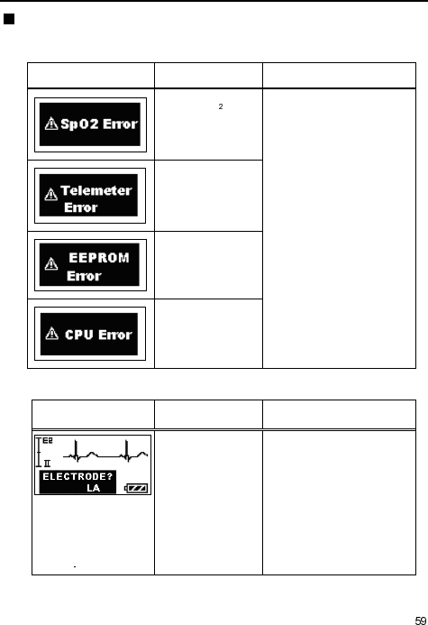
11. Troubleshooting
List of Displayed messages
Transmitter (main unit)
Message Cause Solution
Faulty SpO
module.
Contact your local Fukuda
Denshi service
representative.
Failed to transmit
waveform and
value.
Faulty EEPROM.
Failed to initialize
CPU.
ECG
Message Cause Solution
Electrode is off. Check the electrode
condition.
Character string
displayed, such as LA,
depends on the
detached electrode
position
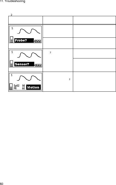
SpO
Message Cause Solution
Probe is off. Check the attached
condition
of the probe.
Faulty Probe. Replace the probe with a
new one.
SpO is not
measured correctly.
Check the attached
condition
of the probe.
Cover the probe with an
opaque material to cut off
the outside light.
Due to excessive
body motion, SpO
is not measured
correctly
Keep the patient still.

Troubleshooting
Make sure of the following. However, if there is no improvement in the
phenomenon, contact your local Fukuda Denshi service representative.
Transmitter (main unit)
Phenomenon Cause Solution
Nothing is displayed
on the LCD when the
power switch is turned
ON.
No battery or wrong
polarity
Install the battery correctly.
Battery level is
empty.
Replace the battery with a
new one.
Nothing is displayed
on the receiving
monitor screen.
The channel
number between
the transmitter and
the receiving
monitor do not
match up.
Set the same channel
number for the transmitter
and the receiving monitor.
Transmission problem.
Same channel
number is already
used.
Make sure to not duplicate
channel numbers.
Follow the instruction by the
person in charge of radio
telemetry channel in your
facility and use the LX-
7230N with the correct
channel setting.
Channel
interference
Follow the instruction by the
person in charge of radio
telemetry channel in your
facility and use the LX-
7230N with the correct
channel setting.
Transmitter failure Contact your local Fukuda
Denshi service
representative.

ECG
Phenomenon Cause Solution
“ELECTRODE?”
message is displayed.
Lead cable is off. Check the connection
between the lead cable and
the LX-7230N.
Check the connection
between the lead cable and
the electrode.
Faulty Lead cable. Replace the ECG cable with
a new one.
Electrode is peeling
off.
Replace the electrode with a
new one.
Polarization
potential of the
electrode is too
high.
Replace the electrode with a
new one.
ECG waveform
contains noise
Electrode gel is dry.
Replace the electrode with a
new one.
Electrode is peeling
off.
Electric blanket is
used.
Cover the electric blanket
with a shield cover.
AC filter setting of
the receiving
monitor is OFF.
Set the AC filter up as ON.
Respiration waveform
cannot be measured.
Electrode gel is dry.
Replace the electrode with a
new one.
Electrode is peeling
off.
The positions of the
electrodes are
improper.
Attach the electrodes where
the respiration waveform can
be measured appropriately.
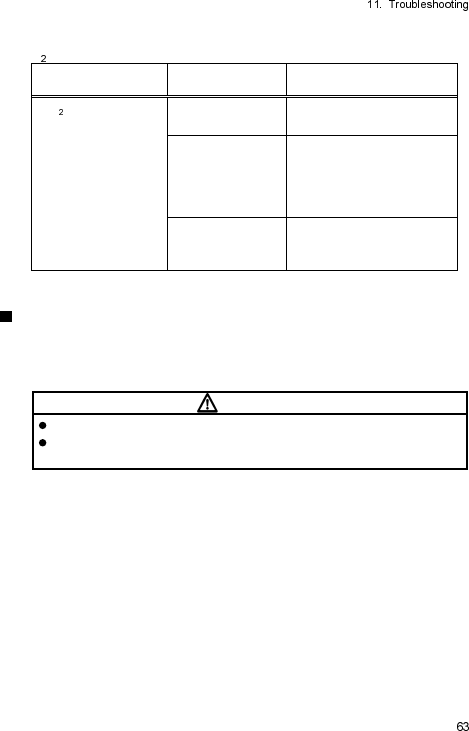
SpO
Phenomenon Cause Solution
SpO value is
unstable.
The probe size is
improper.
Use a probe, which fit
properly.
The probe is
peeling off or is
affected by the
outside light due to
the poor condition
Attach the probe properly
following the instruction.
Transmitting and
measuring LEDs
sensor are dirty.
Clean both LED sensors
from dirt.
In Case of Dropping the LX-7230N into Water
In case of dropping the LX-7230N into water containing disinfectant, pick up
the LX-7230N quickly from it. Rinse it well with running water, and dry it
thoroughly with a soft cloth.
CAUTI O N
Do not use a drier. The LX-7230N shape may change or be broken.
When the LX-7230N is rinsed with running water, make sure to close the
battery compartment lid.
Blank Page
12. Cleaning and Disinfection
The Cleaning and disinfection of the LX-7230N, ECG lead cable, and SpO
probe (sensor) shall be performed as follows.
CAUTI O N
Do not sterilize the LX-7230N, ECG lead cable, and SpO probe (sensor) in
any manners, such as
radioactive rays, steam, or
ethylene oxide.
Cleaning and Disinfecting the LX-7230N
Cleaning
Clean the LX-7230N using squeezed gauze or an absorbent cotton cloth
dampened with alcohol or a neutral cleanser.
CAUTI O N
Clean the equipment frequently so stains can be removed easily.
To prevent injury, it is recommended to wear gloves when cleaning the
equipment.
Do not allow any chemical solution to enter the inside of LX-7230N or
connectors.
The LX-7230N cannot be sterilized.
Do not use organic solvents, thinner, toluene and benzene to avoid
damaging the resin case.
Do not polish the housing with abrasive or chemical cleaner.
Use only neutral detergent to clean the housing. Do not use chemical
cloth, scrub brush, abrasive, polishing powder, hot water, volatile solvent
and chemicals (cleanser, thinner, benzine, benzol, and synthetic
detergent for house and furniture), or sharp-edged tools. The surface
resin coating may be damaged, resulting in discoloration, scratches, and
other problems.
Disinfection
If there is a possibility of being infected, clean the LX-7230N using squeezed
gauze or an absorbent cotton cloth dampened with alcohol or a neutral
cleanser.
CAUTI O N
Do not immerse the connector parts of the LX-7230N in any chemical
solution to prevent connection failure.
When disinfecting the entire room using a spray solution, pay close
attention not to have liquids get into the LX-7230N or connectors.
Cleaning the ECG lead cable
After using the cable, clean it with neutral detergent or 70% isopropyl alcohol.
CAUTI O N
Do not use thinner, toluene, or other organic solvents to clean the cables.
Do not pull the cable and do not hold the connector part when cleaning.
(It may degrade the cable coating and result in damage. Particularly
organic solvents and antiseptic solution such as cresol soap solution will
degrade the cable coating.)
After cleaning, dry it completely before usage.
Do not use high temperature sterilization such as steam or EOG method.
Cleaning and Disinfecting the SpO probe (sensor)
NELLCOR SpO sensors
After using the the Durasensor (DS-100A) on each patient, clean it with 70%
isopropyl alcohol. If low-level disinfection is required, use a 1:10 bleach
solution. Any unproved cleaning solutions may case early failure of the
sensors.
The OxiMax can be reused on the same patient as long as the adhesive tape
attaches without slippage. Do not resterilize and reuse it on other patients. It is
intended for single patient use only.
13. Maintenance and Inspection
This section explains the daily checks and periodic checks of the LX-7230N.
To ensure safety, reliability, and high performance, a “Daily Check” and
“Periodic Check” must be performed. We are not liable for any accident arising
from lack of maintenance.
CAUTI O N
Do not open the housing or attempt service. The service should be done
by Fukuda Denshi or Fukuda Denshi’s representative.
Do not allow excessive moisture or cleaning agents into the connectors
or inside the equipment.
Daily Check
Perform daily checks using the “Daily Check List” on the next page.
Periodic Check
Periodic check of medical electronic equipment is mandatory to prevent
failures and accidents and to ensure safety and reliability.
Periodic maintenance may be performed by the medical institution or by a third
party by concluding a “Maintenance Contract”.
For more details, contact your local Fukuda Denshi service representative.
Periodic Replacement Parts
The “Battery Compartment Lid (Waterproof)” is the only periodic
replacement part.
To ensure the reliability of waterproof (IPX8) performance of the LX-7230N,
replace it once a year.
It may be possible to keep using the LX-7230N without periodic replacement of
the lid. However, as it gets older, the reliability of water resistance (IPX8)
performance will not be ensured.
When replacing the lid, contact your local Fukuda Denshi service
representative.
CAUTI O N
The periodic replacement parts must be replaced at specified period.
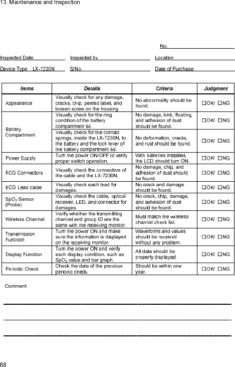
Daily Check List
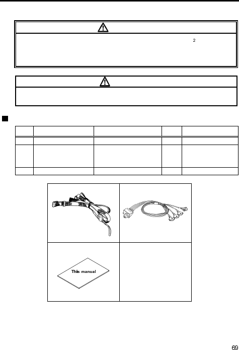
14. Standard and Optional Accessories
This section lists the accessories for the LX-7230N.
WARNI N G
Use only the accessories, such as ECG Lead cable and SpO probe
(sensor), specified by Fukuda Denshi for the LX-7230N. Otherwise, the LX-
7230N cannot deliver its maximum performance and may be damaged,
resulting in a safety hazard.
CAUTI O N
For quality improvement, specifications are subject to change without prior
notice.
Standard Accessories
No.
Item Model Type Q’ty
Note
1 Neck Strap OA-311 1
2 4-electrode ECG
lead cable CMT-02HTH-0.8DA 1
AHA color code,
Hook Type,
Limb Lead (2CH)
3 Operation Manual
1
1. 2.
3.

Optional Accessories
The following accessories are available as optional for the LX-7230N.
Purchase them as required.
ECG, Impedance Respiration Measurement
AHA color code:
Item Model Type Note
ECG Hook Type Lead Cable CMT-01HTH-0.8DA
3-electrode (White,
Black, Red),
Limb Lead (1CH)
ECG Hook Type Lead Cable
CMT-02HTH-0.8DA
4-electrode (White,
Black, Red, Green),
Limb Lead (2CH)
ECG Hook Type Lead Cable
CMT-03HTH-0.8DA
5-electrode (White,
Black, Red, Green,
Brown),
Limb Lead (1CH)+Chest
(1CH)
ECG Clip Type Lead Cable CMT-01FTH-0.8DA
3-electrode (White,
Black, Red),
Limb Lead (1CH)
ECG Clip Type Lead Cable CMT-02FTH-0.8DA
4-electrode (White,
Black, Red, Green),
Limb Lead (2CH)
ECG Clip Type Lead Cable CMT-03FTH-0.8DA
5-electrode (White,
Black, Red, Green,
Brown),
Limb Lead (1CH)+Chest
(1CH)
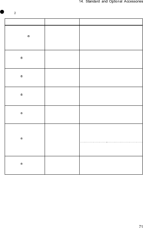
SpO Measurement
Item Model Type Note
Durasensor DS-100A
Reusable
Multiple-Patient, Multiple-Use
Adult
(weight of 40Kg and over)
Finger
OxiMax MAX-P
Single-Patient, Single-Use
Pediatric
(weight of 10 to 50Kg)
Finger
OxiMax MAX-A/AL
Single-Patient, Single-Use
Adult
(weight of 30Kg and over)
Finger
OxiMax MAX-I
Single-Patient, Single-Use
Infant
(weight of 3 to 20Kg)
Toe
OxiMax MAX-R
Single-Patient, Single-Use
Adult
(weight of 50Kg and over)
Nose
OxiMax MAX-N
Single-Patient, Single-Use
Adult
(weight of 40Kg and over)
Finger
Neonate
(weight of less 3Kg)
Foot
OxiMax MAX-FAST
Single-Patient, Single-Use
Adult /Pediatric
(weight of 10Kg and over)
Forehead

Blank Page
15. Specification
Specification
CAUTI O N
For quality improvement, specifications are subject to change without prior
notice.
Standard Specification
Size: 72.0(W) x 98.0(H) x 24.8(D)mm (not including the
protrusion)
Weight:
A
pproximately 190 grams (with batteries)
Transmitting
Waveform:
ECG 1CH or 2CH (selectable from the ECG lead
cable), Respiration waveform, pulse waveform (with
SpO value)
ECG Lead cable Type:
3-electrode, 4-electrode, or 5-electrode (Limb+Chest)
lead cable
Automatically
detect the type after inserting the lead
cable
Transmitting Status
Data:
Electrode Off, Low Battery, Event Switch, Pacemaker
Detection, Channel ID, 64group Codes, SpO Sensor
Off
LCD: Built-in
Waterproof: IPX8
Power Supply: DC: Two 1.5 V “AA” size (“LR06” size) alkaline
batteries
Continuous Operating
Time:
A
pproximately 1.5 days
*Continuous operating time is assumed when using new “AA” size (“LR06”
size) Alkaline batteries specified by Fukuda Denshi.
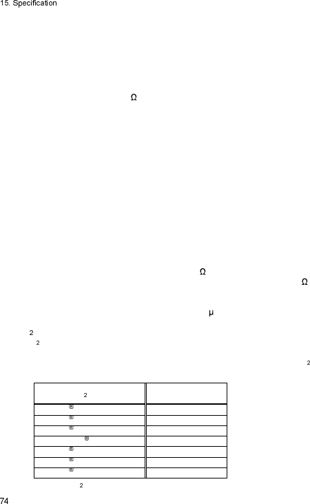
ECG
Numbers of Lead
Electrode:
3-electrode, 4-electrode, or 5-electrode
(Limb+Chest)
Numbers of Input
Channel:
1CH(3-electrode) or 2CH
Accuracy of Sensitivity
: 10mm /1mV ± 20%
(Display sensitivity on the receiving monitor)
ECG Input Impedance: 5M and above
Maximum Input Voltage: ±5mV and above
Common Mode Rejection
Ratio:
Less than 10mVp-p (95dB and above)
Accuracy of Heart Rate
Measurement:
±10% or ±5bpm, whichever is greater
HR Display Range: 0, 12 to 300bpm (1bpm step)
Frequency
Characteristic:
0.5 to 40Hz (within -3dB)
Time Constant 0.4 sec ±25%
Switching and available to set 0.1 sec ±25
Pacemaker Pulse
Detection/ Rejection:
Comply with ANSI/AAMI EC13 Pacemaker pulse
rejection capability
Protection to
Defibrillation:
Meet the requirement of IEC60601-2-27
Respiration (Impedance Method)
Accuracy of Sensitivity: 10mm/1 ±2mm
(When standard Impedance is 480 .)
Resp. Display Range: 0, 9 to 150Bpm
Display Error of Respiration Rate: ±3Bpm
Measured Current of Respiration: Below 100 A (at 42kHz)
SpO
SpO Measurement Range: 1 to 100%
Resolution: 1%
Measurement Accuracy: Accuracy of measurement with SpO
Probe is as follows.
SpO Probe Measurement
Accuracy (±1SD)
OxiMax MAX-I ±2%
OxiMax MAX-P ±2%
OxiMax MAX-A/AL ±2%
Durasensor DS-100A ±3%
OxiMax MAX-R ±3.5%
OxiMax MAX-FAST ±2%
OxiMax MAX-N ±2%
(When SpO is 70 to 100%. Less than 70% is not specified.)
Wavelength:
Approx.
660nm (Red light)
Approx. 900nm (Infrared light)
Optical output power: Under 15mW
Measurement Response Time: 6 to 7 sec. (Averaging time)
Measurement Value Update Rate:
1 second
NOTE
The SpO measurement accuracy is determined based on the values of
the root-mean-square (rms) difference between SpO readings of the pulse
oximeter equipment and values of SaO determined with a CO-oximeter,
by healthy adult volunteers. The pulse oximeter equipment measurements
are statistically distributed; ±2% measurement accuracy means that only
about two-thirds of pulse oximeter equipment measurements can be
expected to fall within ±2% of the value measured by a CO-oximeter.
US Patents
Covered by one or more of the following U.S. patents and foreign
equivalents:
5,485,847; 5,676,141; 5,743,263; 6,035,223; 6,226,539; 6,411,833;
6,463,310; 6,591,123; 6,708,049; 7,016,715; 7,039,538; 7,120,479;
7,120,480; 7,142,142; 7,162,288; 7,190,985; 7,194,293, 7,209,774;
7,212,847; 7,400,919.
Pulse Wave
Pulse Rate Measurement Range: 20 to 250bpm
Measurement Accuracy: ±3bpm
Measurement Response Time: 6 to 7 sec. (Averaging time)
Measurement Value Update Rate: 1 second
Transmission Method
Modulation Mode: Digital, Frequency shift keying
Frequency: 1395 to 1400MHz , 1427 to 1432 MHz
Oscillation Method: PLL Synthesizer method by crystal control
Channel Spacing: 25kHz
Occupied Frequency
Bandwidth:
16kHz
RF output power: 5mW ±2dB
Transmitting Antenna: ECG lead cable and/or SpO Probe
Safety
General Standard:
IEC 60601-1: 1988 +A1: 1991 +A2: 1995
(Medical electrical equipment – Part 1: General
requirements for safety)
EMC Standard: IEC 60601-1-2: 2007
(Medical electrical equipment – Part 1: General
requirements for safety – 2. Collateral standard:
Electromagnetic compatibility – Requirements and tests)
The class of
protection
against electric
shock:
Internally Powered Equipment
The type of
protection
against electric
shock:
Type CF Applied part
Operating Environment
Temperature: 10 to 40 C
Humidity: 30 to 85% RH (No condensation)
Vibration/Shock:
Comply with IEC60068-2-64:1987, IEC60068-2-32:1975,
IEC60068-2-6:1995
Transport / Storage Environment
Temperature: -10 to 60 C
Humidity: 10 to 95% RH (No condensation)
Functional Testers and Patient Simulator for SpO measurement
Some models of commercially available bench top functional testers and
patient simulators can be used to verify the proper functionality of pulse
oximeter sensors, cables and pulse oximeters. See the operator’s manual
of the individual testing device for the procedure which is specific to the
model of tester being used.
While such devices may be useful for verifying that the pulse oximeter
sensor, cabling, and pulse oximeter are functional, they are incapable of
providing the data required to properly evaluate the accuracy of a system's
SpO measurements.
Fully evaluating the accuracy of the SpO measurements requires, at a
minimum, accommodating the wavelength characteristics of the sensor
and reproducing the complex optical interaction of the sensor and the
patient’s tissue. These capabilities are beyond the scope of known bench
top testers.
SpO measurement accuracy can only be evaluated in vivo by comparing
pulse oximeter readings with values traceable to SaO measurements
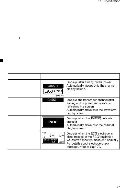
obtained from simultaneously sampled arterial blood using a laboratory
Co-oximeter.
Many functional testers and patient simulators have been designed to
interface with the pulse oximeter's expected calibration curves and may be
suitable for use with pulse oximeters and/or sensors. Not all such devices,
however, are adapted for use with the calibration system. While this will
not affect use of the simulator for verifying system functionality, displayed
SpO measurement values may differ from the setting of the test device.
For a properly functioning pulse oximeter, this difference will be
reproducible over time and from pulse oximeter to pulse oximeter within
the performance specifications of the test device.
Displays
The following displays are shown on the LCD of the LX-7230N.
Display Description
Starting Screen
Channel Display
Screen
EVENT
ELECTRODE?
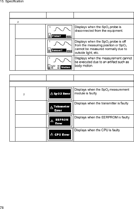
Display Description
SpO measurement Status
Probe?
Sensor?
Motion
Display Description
Error Message
SpO Error
Telemeter Error
EEPROM Error
CPU Error
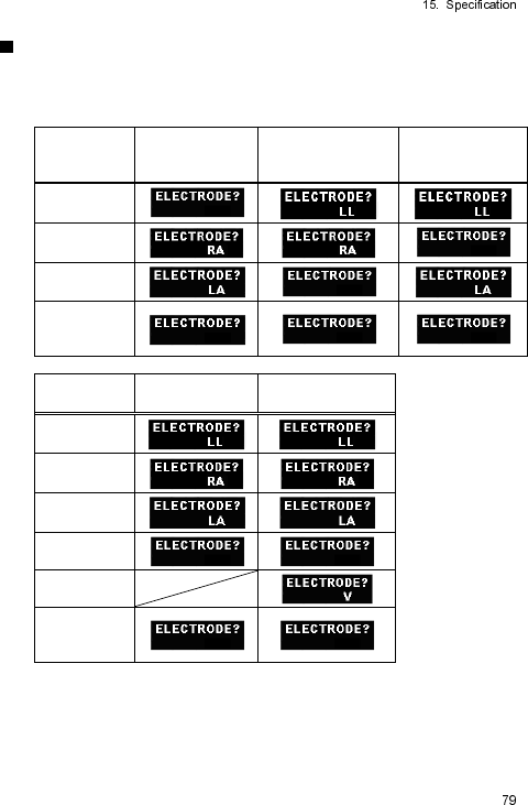
Details of the “ELECTRODE?” Message
The following “ELECTRODE?” messages are displayed on the LCD depending
on the selected lead cable and lead.
For AHA color code
Check
Position
3-electrode lead
cable
Lead I display
3-electrode lead
cable
Lead II display
3-electrode lead
cable
Lead III display
LL
RA
LA
Several
Position
Simultaneously
Check
Position
4-electrode lead
cable
For 5-electrode
(Chest) lead cable
LL
RA
LA
RL
V
Several
Position
Simultaneously
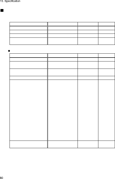
List of Setup Items
This section lists the available selection, default setting, and backup status
for each setup item, which is available for the LX-7230N.
Items Selection Default Backup
ECG Lead I, II, III II Yes
Display Size of ECG (1)
×1, ×1/2 ×1 Yes
Display Size of ECG (2)
×1, ×1/2 ×1 Yes
Display Size of
Respiration Waveform ×1, ×1/2 ×1 Yes
For details of the following settings, contact our service representative.
Items Selection Default Backup
Time Constant 0.4 sec., 0.1 sec. 0.4 sec. Yes
Detection Sensitivity of
Pacemaker Pulse Low, Mid, High Mid Yes
Respiration Detection
Signal ON, OFF ON Yes
LCD Contrast 8 steps 8 Yes
Transmitter Channel
One from the
following channels.
9501to 9539
9600 to 9639
9700 to 9739
9700 to 9739
9800 to 9839
9900 to9938
2701 to 2739
2800 to 2839
2900 to 2918
2921 to 2939
3000 to 3039
3100 to 3138
9501 Yes
Group ID One from 00 to 63
00 Yes

Printed in Japan 4L0112040 201411
3-39-4 Hongo, Bunkyo-ku, Tokyo, Japan
Tel: +81-3-5684-1455 Fax: +81-3-3814-1222
http://www.fukuda.com