Fukuda Denshi Co LX8100 ECG & Respiration Transmitter User Manual 4L0114970 LX 8100 FA V01
Fukuda Denshi Co Ltd ECG & Respiration Transmitter 4L0114970 LX 8100 FA V01
UserManual.wiki
>
Fukuda Denshi Co
>
LX8100 User Manual
05 (Short-Term Confidential) User Manual
Navigation menu
Upload a User Manual
Namespaces
Wiki Guide
HTML
PDF
Info
Views
User Manual
Discussion / Help
Navigation
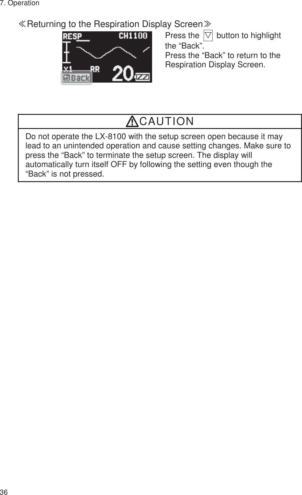
![viii Defibrillation Safety WARNING z Use only the lead cable specified by Fukuda Denshi when defibrillating. If used by unspecified lead cable, the equipment may be damaged, resulting in a safety hazard. z When using the defibrillator, keep away from the electrodes or medicament applied to the patient chest. If this is not possible, remove the electrodes or medicament before using it. If the defibrillator paddles are directly in contact with the electrodes or medicament, an electrical shock may result from the discharged energy. z When using the defibrillator, do not touch the patient and the metal part of the equipment or cables. Electric shock may result from the discharged energy. Precautions about the Pacemaker WARNING z Minute ventilation rate-adaptive implantable pacemakers can occasionally interact with certain cardiac monitoring and diagnostic equipment, causing the pacemakers to pace at their maximum programmed rate. The cardiac monitoring and diagnostic equipment may possibly send wrong information. If such event occurs, disconnect the cardiac monitoring and diagnostic equipment, or follow the procedures described in the operation manual of the pacemaker. (For more details, contact FUKUDA DENSHI personnel, your institution’s professionals, or your pacemaker distributors.) z Rate meters may continue to count the pacemaker rate during occurrences of cardiac arrest or some arrhythmias. Do not rely entirely upon rate meter alarms. Keep pacemaker patients under close surveillance. Reference “Minute Ventilation Rate-Adaptive Pacemakers” FDA alerts health professionals that minute ventilation rate-adaptive implantable pacemakers can occasionally interact with certain cardiac monitoring and diagnostic equipment, causing pacemakers to pace at their maximum programmed rate. [October 14, 1998 – FDA]](https://usermanual.wiki/Fukuda-Denshi-Co/LX8100/User-Guide-3646813-Page-10.png)


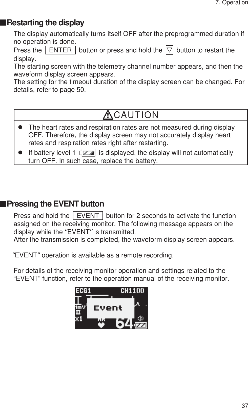
![17 5. Respiration Monitoring Follow the preparation of “4. ECG Monitoring” to allow the respiration monitoring. This respiration monitoring is performed with impedance method. The ECG electrodes are also used for detecting the respiration. Each lead cable specifies the electrodes to detect the respiration. For 3-electrode and 5-electrode (chest) lead cable, the electrodes to detect the respiration are fixed as follows. Even if lead method is switched, they are no changes. Lead Cable Color of Electrode 3-electrode White (RA) and Red (LL) 4-electrode White (RA) and Red (LL) 5-electrode (Chest) White (RA) and Red (LL) WARNING Minute ventilation rate-adaptive implantable pacemakers can occasionally interact with certain cardiac monitoring and diagnostic equipment, causing the pacemakers to pace at their maximum programmed rate. The cardiac monitoring and diagnostic equipment may possibly send wrong information. If such event occurs, please disconnect the cardiac monitoring and diagnostic equipment, or follow the procedures described in the operation manual of the pacemaker. (For more details, contact FUKUDA DENSHI personnel, your institution’s professionals, or your pacemaker distributors.) Reference “Minute Ventilation Rate-Adaptive Pacemakers” FDA alerts health professionals that minute ventilation rate-adaptive implantable pacemakers can occasionally interact with certain cardiac monitoring and diagnostic equipment, causing pacemakers to pace at their maximum programmed rate. [October 14, 1998 – FDA] CAUTION z Even if the electrodes are attached on the proper positions for ECG monitoring, it may not be always the proper ones for respiration monitoring as well. z When a defibrillator is used during respiration monitoring, a large offset voltage will be placed on the ECG electrodes, which may cause interruption of monitoring for a few seconds.](https://usermanual.wiki/Fukuda-Denshi-Co/LX8100/User-Guide-3646813-Page-39.png)