Fulcrum ML10 WIRELESS REMOTE CONTROL SWITCH User Manual WRC Switch Instructions
Fulcrum Products, Inc. WIRELESS REMOTE CONTROL SWITCH WRC Switch Instructions
Fulcrum >
User Manual
30min 60min 120min
Wireless Remote Control Switch
Operating Instructions
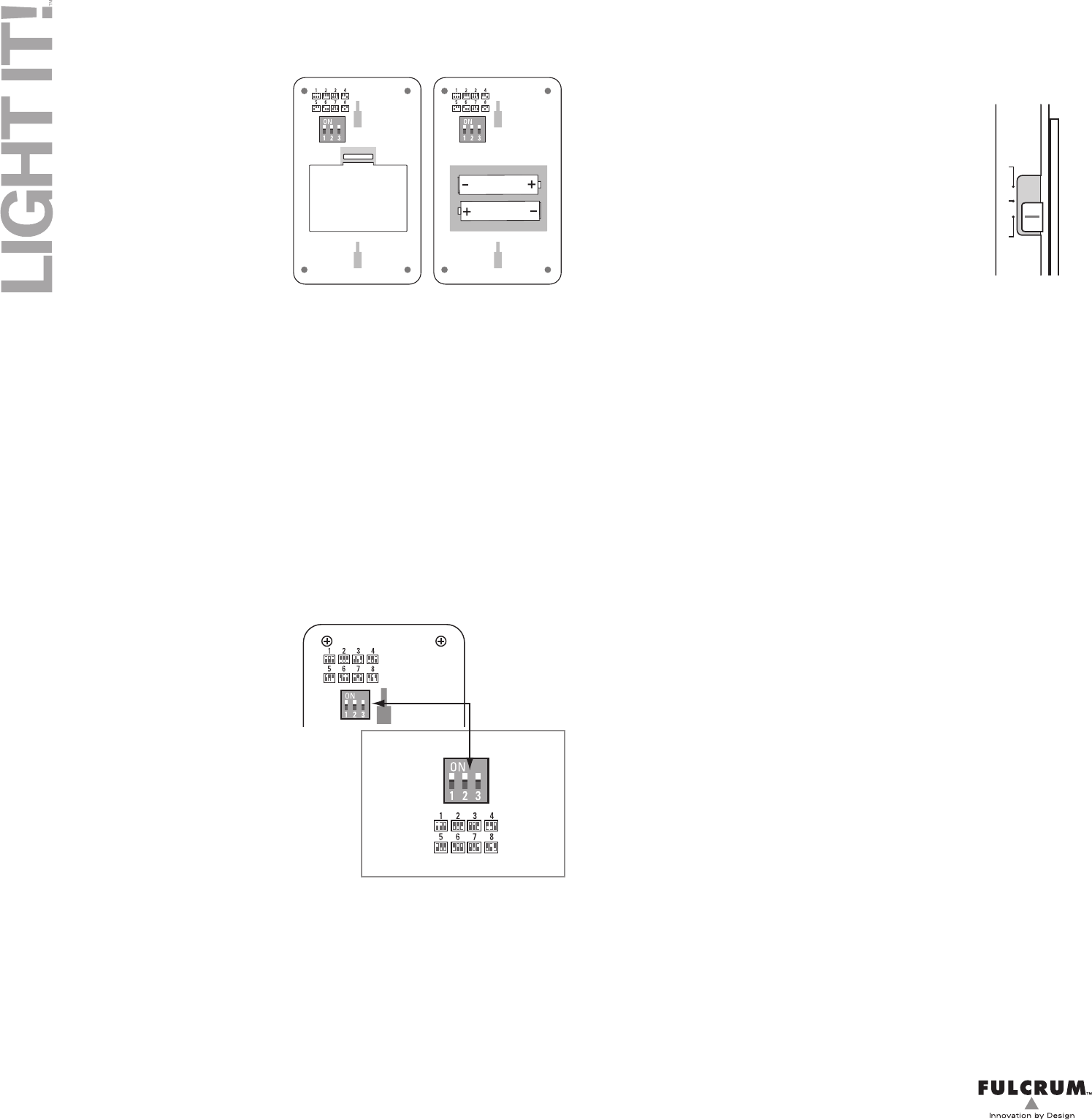
Battery Installation & Replacement
1) Remove the battery cover by depressing
the tab on the back of the switch as shown
in the diagram.
2) Install 2 AAA batteries making certain to
match the polarity as shown in the diagram
in the battery compartment.
3) Do not mix battery types. Use only fresh
batteries. Alkaline are recommended.
4) Check the switch operation to confirm
that batteries are correctly installed.
5) Replace the battery cover.
Operating the Lights with the Wireless Remote Control Switch
You can operate the lights one of two ways: manually or by using a wireless remote control switch.
Manual Operation
Follow the instructions provided with the light you are operating.
RC System Compatible
Use any combination of up to 20 RC lights or switches to solve your lighting problems.
Remote Control Switch Operation
1) Press the on symbol I once to turn the lights on.
2) Press the off symbol O once to turn the lights off.
3) To dim the lights, press and hold the on symbol I until the desired light level is reached, then
release. Please note that some light types cannot be dimmed using the remote switch.
Group Code/ DIP Switches
Each light and switch comes with 3 DIP switches that enable the user to operate 2 or more groups
of lights without interfering with each other. These switches come preset from the factory and will
not require adjustment unless:
1) You are adding lights to the group, or
2) You are operating 2 or more groups of
lights within 60’ of each other.
Adding Lights to Your Group
1) Remove the battery cover.
2) Use a pointed object to gently move the DIP
switches to match the settings on the switch.
3) Check operation by pressing the switch
on and off.
4) Replace the battery cover.
5) Repeat the process with all of the remaining
lights in the group.
Adding Switches to Your Group
1) Simply follow the instructions above and arrange
the 3 DIP switches to match the code of the group to which you are adding lights.
2) We do not recommend groups in excess of 20 lights and switches (total combined).
Installing additional Lights
The chief benefit of using 433Mhz radio frequency control is that it works through most common
barriers (walls, clothing, shelving, etc.) and so does not require line of sight operation as is the
case with infrared systems.Therefore you can choose a switch location that is most convenient for
you to operate the system. You can locate the lights where they are needed most without concern
for the barriers that might exist. This provides the user with enormous flexibility. Lights can be
located in different rooms, different closets, or even on different floors of the house if desired.
We recommend choosing the desired location for the lights and testing the operation of the system
before commencing the actual installation. Locate the lights where they are most needed without
regard for physical barriers and test by turning them on and off several times. You may occasional-
ly experience a slight delay in one or more lights. This is normal. Although we have made every
effort to synchronize the operation of these lights, external conditions may cause a slight delay and on
rare occasions the lights may not turn on or off. If this happens, simply turn the lights off and then on
again. If it happens repeatedly, there may be external factors that are disrupting the signal and the
location of the light may need to be altered. Once the final location of the lights has been determined,
please remove the battery cover and follow steps below to mount the light.
Please note: For optimal performance we recommend installing the lights
12” or more apart from each other.
Battery Saver
To prevent unintended battery use, the Wireless Remote
Control Switch comes with 3 user-selectable settings: 30,
60 or 120 minutes. The Switch will automatically shut off
the lights should you forget. This feature cannot be turned
off. Only the time period can be selected.
Mounting Instructions
Determine the location of the lights and switch, as noted above, then remove the mounting plate from the
switch and the battery cover/mounting plate from the light and follow the steps below to mount them.
Double-sided Tape Mounting: Be certain that the intended mounting surface is clean, dry, and
suitable for attachment. Take care to select a location that will not be damaged by the adhesive tape.
Remove the protective film and apply the tape to the mounting bracket. Peel off the protective film and
press the mounting bracket firmly to the intended surface.
Screw Mounting – Wood Surfaces: Drill a 1/16” pilot hole, insert the screw and gently tighten it
until the mounting plate is secure. Do not over tighten.
Screw Mounting – Drywall: Drill a 3/16” pilot hole, insert the drywall anchor and press firmly until it
is fully seated into the wall. Insert the screw and gently tighten it until the mounting plate is secure. Do
not over tighten.
FCC Statement
This device complies with Part 15 of the FCC Rules. Operation is subject to the following two conditions:
(1) This device may not cause harmful interference, and
(2) this device must accept any interference received, including interference that may cause undesired
operation.
NOTE: This equipment has been tested and found to comply with the limits for a Class B digital
device, pursuant to Part 15 of the FCC Rules. These limits are designed to provide reasonable
protection against harmful interference in a residential installation. This equipment generates, uses
and can radiate radio frequency energy and, if not installed and used in accordance with the
instructions, may cause harmful interference to radio communications.
However, there is no guarantee that interference will not occur in a particular installation. If this
equipment does cause harmful interference to radio or television reception, which can be determined by
turning the equipment off and on, the user is encouraged to try to correct the interference by one or more
of the following measures:
• Reorient or relocate the radio or TV antenna.
• Increase the separation between the lights and the radio or TV.
• Consult the dealer or an experienced radio/TV technician for help.
Limited 1 Year Warranty
This product is guaranteed against defect and workmanship for a period of 1 year from the date of
purchase. If the product fails during normal use, please return it to the place of purchase together with a
copy of the sales receipt. Alternatively, you may contact us at info@fulcrumproducts.com and we will
arrange to have the product replaced or repaired at our discretion.
WARNING: Modifications to this or other products by anyone other than an authorized repair agent may
void that product’s warranty.
Fulcrum Products, Inc. • info@fulcrumproducts.com • 503-274-1227
The switch positions
on the light should
match the switch
positions on the
switch
SWITCH
BACK OF LIGHT
The battery saver is
located on the left
side of the switch
Specications – Model # 30019-308
Operating Mode: 433MHz radio frequency control
Operating Distance: 60’
Battery Type: AAA (x2), alkaline recommended
Battery Standby Life: approx. 30 months, actual
battery life will vary according to frequency of use.
Included Items
Double-sided adhesive tape • Screws & drywall anchors
Operating Instructions
CAUTION
Do not mix battery types
Use only fresh batteries for reliable operation