Furuno USA 9ZWFA100 Universal Automatic Identification System User Manual OPERATORS MANUAL
Furuno USA Inc Universal Automatic Identification System OPERATORS MANUAL
Contents
- 1. OPERATORS MANUAL
- 2. Frequency And Channel Usage
- 3. UPDATED CHANNEL LIST
OPERATORS MANUAL
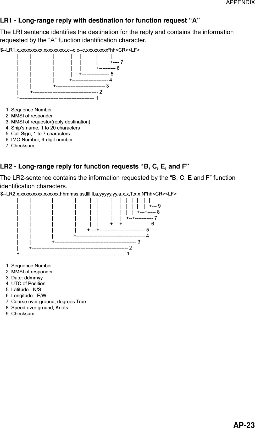
![11 OPERATION 1.1 Description of Controls 8TUVABC2PQRS7WXYZ9NEXT MENUENTSFT+/-6MNO5JKL4GHICLRALM0_,.POWERFURUNO*1DDDD3DEFDDDDCONT/BRILL FA-100 Transponder unit Description of controls Control Description 0 - 9 Alphanumeric, symbol input keys 2(▲) and 8(▼) Adjust display brilliance and keyboard backlighting; scroll display. 4(◄) and 6(►) Shift the cursor left and right (pressed with [SFT/ +/-]), respectively; adjust contrast. CLR/ALM Clears an entry; silences the audio alarm. SFT/ +/- Selects numeric or alphabet entry mode alternately; selects options on menus. CLR/ALM + SFT/ +/- Change the contrast and brilliance. ENT Concludes an entry. NEXT Chooses next line. Press together with [SFT/ +/-] to shift cursor in reverse direction. MENU Displays menu. Also used to perform “escape”. POWER Turns the power on and off.](https://usermanual.wiki/Furuno-USA/9ZWFA100.OPERATORS-MANUAL/User-Guide-275594-Page-11.png)
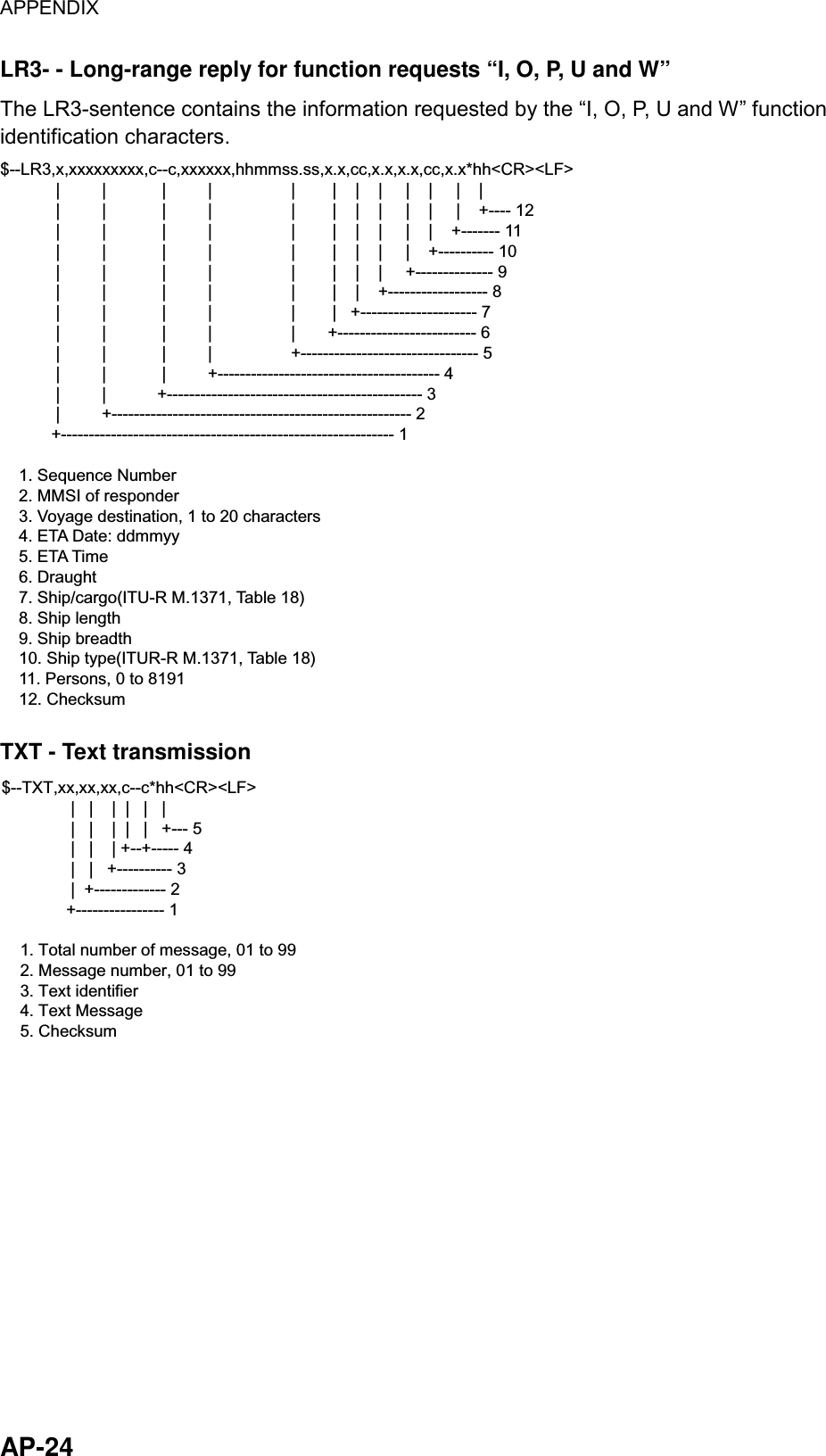
![1 OPERATION 21.2 Turning On and Off Press the [POWER] key to turn the equipment on and off. The startup screen appears. Showing FURUNO logo along with the date and time of last power-off. SHUT DOWN26/AUG/200205:46:52Date and time oflast power-off. Startup screen After the FURUNO logo disappears, the screen displays “NOW STARTING…CHECKING MEMORY. At this time the BIIT (built-in integrity test facility) checks the major circuits including RAM, ROM, interface, etc. The plotter display appears, showing the message “NOW SORTING.” This means the equipment is sorting targets by distance, from closest to furthest. This takes several seconds to complete. [- - - - - -]SOG:- - -.- ktCOG:- - -.- degINTRD: 0[ ]: FWD[ ]: BACK RNG: 1.50 nm"Please Wait!" is shown whenno data is being received. PLOTTER display The FA-100 should be powered while underway or at anchor. The master may switch off the AIS if he believes that the continual operation of the AIS might compromise the safety or security of his ship. The AIS should be restarted once the source of danger has disappeared. The equipment transmits own ship static data within two minutes of start-up and it is transmitted at six-minute intervals. Static data includes MMSI number, IMO number, call sign, ship name, ship length and width, ship type and GPS antenna position. In addition to static data, ship’s dynamic data is also transmitted. This data includes position with accuracy, SOG, COG, rate of turn, heading, etc. Dynamic data is transmitted ever 2 s to 3 min depending on ship’s speed and course change, voyage-related data, such as ship draft, hazardous cargo, destination and estimated time of arrival, are transmitted at six-minute intervals.](https://usermanual.wiki/Furuno-USA/9ZWFA100.OPERATORS-MANUAL/User-Guide-275594-Page-12.png)
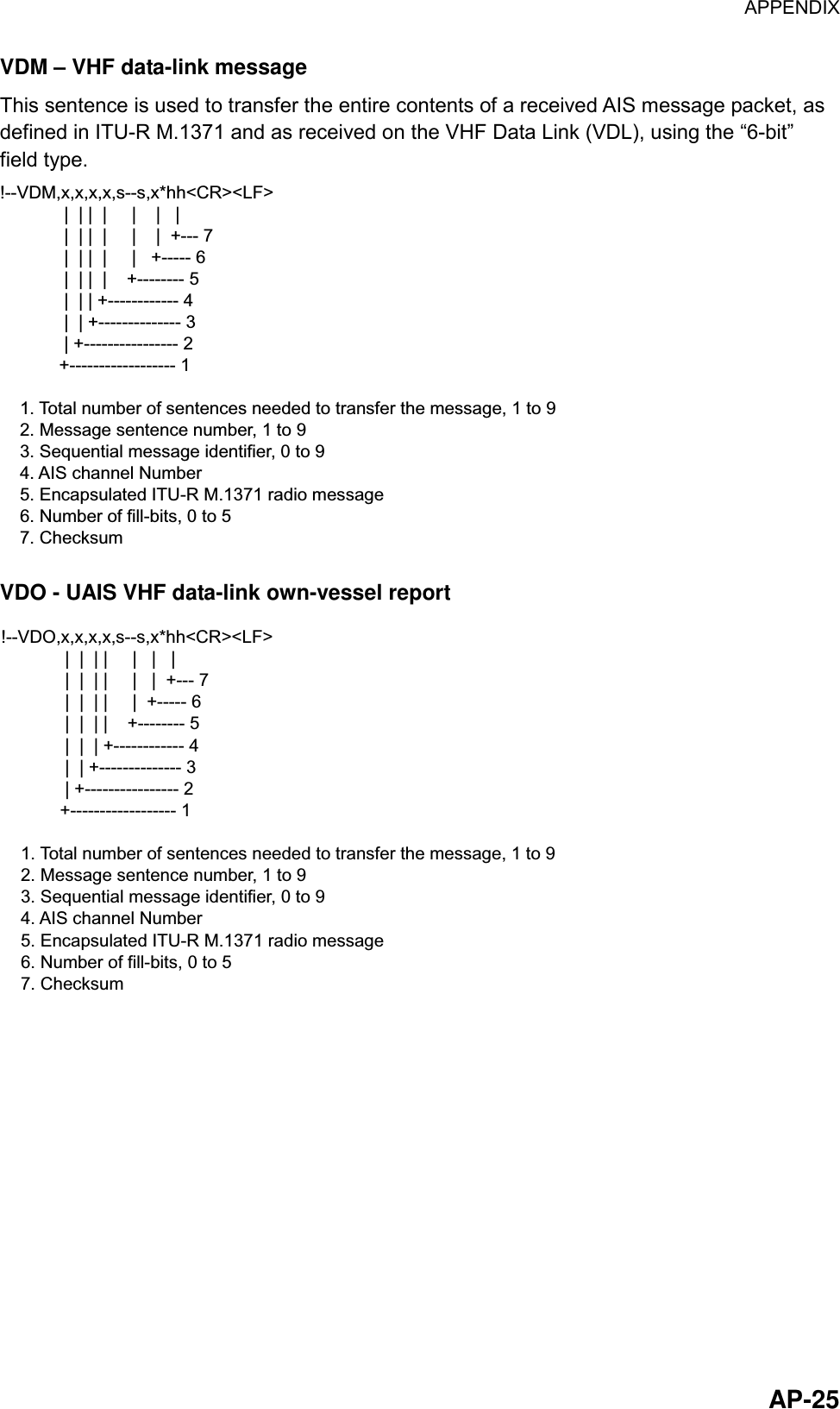
![1 OPERATION 3The FA-100 starts receiving data from AIS-equipped ships as soon as it is turned on, and the ships’ location on the plotter display is shown with the AIS symbol. (To learn more about the plotter display, see paragraph 1.7.) With connection of a radar or ECDIS, the AIS target symbols may be overlaid on the radar or ECDIS. Note 1: If no navigation sensor is installed or a sensor such as a gyrocompass has failed, the AIS automatically transmits “not available” data. Note 2: The reporting intervals are as follows Ship’s navigation status and reporting interval Ship’s navigation status Reporting interval Moored 3 min 0-14 kt speed 10 s 0-14 kt speed with course change 3+1/3 s 14-23 kt speed 6 s 14-23 kt speed with course change 2 s Speed higher than 23 kt 2 s Speed higher than 23 kt with course change 2 s 1.3 Adjusting Display Brilliance and Contrast 1. Press the [CLR/ALM]+[SFT/ +/-] keys together to show the dialog box below. BRILLIANCECONTRASTESC:[ENT]TSWX Dialog box for adjustment of brilliance and contrast 2. Use the [▲] or [▼] key to adjust brilliance; [◄] or [►] key to adjust contrast. 3. Press the [ENT] key to close the dialog box. Note: If you turn off the equipment with minimum contrast, the startup screen is displayed in high contrast at the next power-on. However, the plotter display, which appears after the startup screen, will be shown in minimum contrast. Therefore, adjust the contrast as described above.](https://usermanual.wiki/Furuno-USA/9ZWFA100.OPERATORS-MANUAL/User-Guide-275594-Page-13.png)
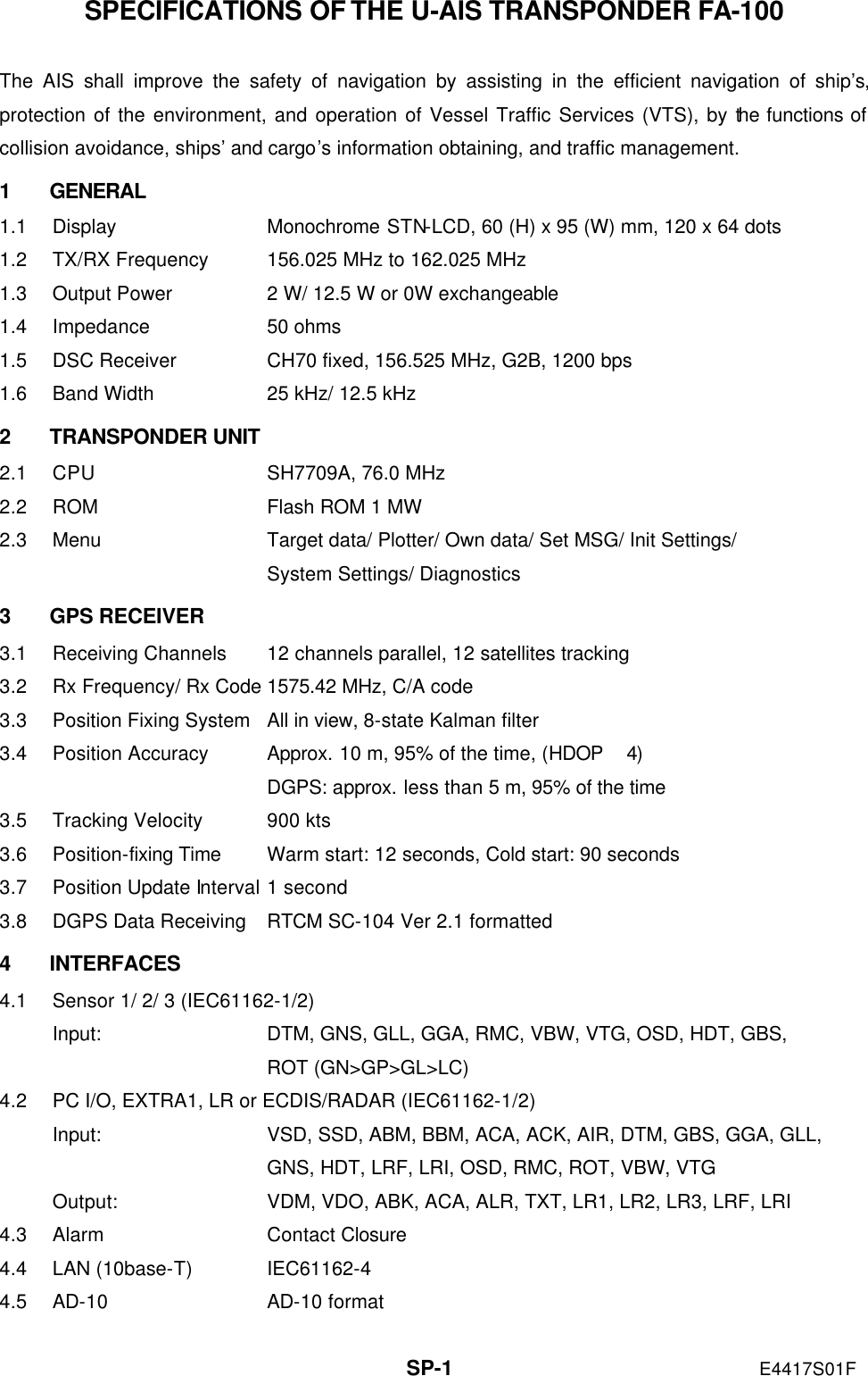
![1 OPERATION 41.4 Menu Overview You can choose the functionality of the equipment through the menu. If you get lost in operation, press the [MENU] key until you return to the main menu. The complete menu tree is provided in the Appendix. 1.4.1 Menu operating procedure 1. Press the [MENU] key to display the main menu. [MENU] 1 TARGET DATA 2 PLOTTER 3 OWN DATA 4 SET MSG 5 INIT SETTINGS 6 SYSTEM SETTINGS 7 DIAGNOSTICSAsterisk markscurrent selection. Main menu 2. Press appropriate numeric key to choose a wanted sub-menu. For example, press the [6] key to choose the SYSTEM SETTINGS sub-menu. (You may also choose a sub-menu by pressing the [NEXT] key to choose it and then pressing the [ENT] key.) [SYSTEM SETTINGS] 1 SET I/O PORT 2 SET CHANNEL 3 SET LR MODE 4 SET OTHER I/O 5 SET BUZZER SYSTEM SETTINGS sub-menu 3. Press appropriate numeric key to choose sub-menu desired. For example, press the [5] key to show the SET BUZZER sub-menu. [SET BUZZER] ALARM : OFF CPA/TCPA: OFF +-"+/-" means to use the[SFT/ +/-] key to choosedesired option.+- SET BUZZER sub-menu 4. Choose item with the [NEXT] key. The asterisk shows current selection. 5. Depending on the sub-menu shown, use the alphanumeric keys to enter data, or use the [SFT/ +/-], [▲], [▼], [◄] or [►] key to choose data. 6. Press the [ENT] key to register data. 7. Press the [MENU] key several times to return to the main menu.](https://usermanual.wiki/Furuno-USA/9ZWFA100.OPERATORS-MANUAL/User-Guide-275594-Page-14.png)
![1 OPERATION 51.4.2 Remarks on menu operation Confirming entry If, after you have changed data, you pressed the [MENU] key without pressing the [ENT] key, the message shown below appears. If you want to cancel the data, press the [ENT] key. If you wish to save, use the [▼] key to choose NO, press the [ENT] key and then press the [ENT] key again. CANCEL? YES NO +/- “Are you sure” confirmation dialog Choosing data input mode To enter a specific numeric, alphabet or symbol, choose the appropriate data input mode, numeric or alphabet. The active data input mode is shown at the bottom left-hand corner of the screen. Use the [SFT/ +/-] key to select desired mode. To enter a numeric, simply press appropriate numeric key. For alphabet or symbol, press appropriate key until desired character or symbol appears. [SET MSG]123 0/150Data Input Mode123: NumericABC: AlphabetUse the [SFT/ +/-] keyto switch modes. SET MSG screen](https://usermanual.wiki/Furuno-USA/9ZWFA100.OPERATORS-MANUAL/User-Guide-275594-Page-15.png)
![1 OPERATION 6Shifting the cursor To shift the cursor backward or forward, press [SFT/ +/-] + [◄] together to shift it backward; [SFT/ +/-] + [►] together to shift it forward. This is convenient for creating a space or using the same key consecutively. Multiple page sub-menus Some sub-menus have more than one page. In this case, an arrow(s) appears at the top of the display to show which arrow key(s) to press to change the page. [OWN STATIC DATA2] DESTINATION: TOKYO DATE : 12/FEBTIME : 10:25[OWN STATIC DATA1] NAME : SHIPC. SIGN: CAL0001MMSI : 123456789IMO# : 623498071[OWN STATIC DATA5] CREW : 12TYPE : 36 CLASS : A TYPE NAMESAILINGPage 1 of sub-menu.Press [ ] to go to next page.Intermediate page insub-menu. Press [ ]to go to next page;[ ] to go to previouspage. Last page of sub-menu.Press [ ] to go to previous page. OWN STATIC DATA displays 1, 2 and 5 Choosing options Menu options may be chosen with the [▲], [▼], [◄] or [►] key or [SFT/ +/-] key depending on the sub-menu. In the examples below, you may choose NAV STATUS option with the [▲], [▼], [◄] or [►] key and ALARM option with the [SFT/ +/-] key. STATUS NAMEUse thesearrow keysto choosean option.[SET STATUS] NAV STATUS: 00 UNDER WAY USINGENGINE (DEFAULT)-Use the[SFT/ +/-] keyto choosean option.[SET BUZZER] ALARM : OFF CPA/TCPA: OFF +-+- SET STATUS sub-menu Saving settings When the [MENU] key is pressed after changing an option (to register setting), you are asked if you want to save the setting. To save the setting, press the [ENT] key. To retain the previous setting, select NO and press the [ENT] key. To escape, choose [CANCEL] and press the [ENT] key. SAVE? YES NO CANCEL +/- Save confirmation dialog](https://usermanual.wiki/Furuno-USA/9ZWFA100.OPERATORS-MANUAL/User-Guide-275594-Page-16.png)
![1 OPERATION 71.5 Setting Up for a Voyage There are five items on the INIT SETTINGS menu (Menu #5) you will need to enter at the start of a voyage: draught, destination, navigation status, ship type and number of crew. 1. Press the [MENU] key to open the main menu. 2. Press the [5] key to open the INIT SETTINGS menu. [INIT SETTINGS] 1 SET SHIP DATA 2 SET DESTINATION 3 SET NAV STATUS 4 SET TYPE&CREW 5 SET CPA/TCPA 6 SET ANTENNA POS INIT SETTING sub-menu 3. Press the [1] key to choose SET SHIP DATA. The ship’s name and call sign have been entered at installation. Confirm that they are correct. +-123[SET SHIP DATA] NAME : FURUNO C. SIGN : 6LCZ43B DRUGHT : 12.3 m DTE : DEFAULT SET SHIP DATA sub-menu 4. Press the [NEXT] key to choose DRUGHT (draught). 5. Use the numeric keys to enter ship’s current draught for the voyage. (Be sure to amend it if it changes during the voyage.) Note: DTE should not be changed from "DEFAULT." 6. Press the [ENT] key to register data and return to the INIT SETTINGS menu. 7. Press the [2] key to choose SET DESTINATION. [SET DESTINATION]DATE: 00/00 (DD/MM) TIME: 00:00DESTINATION: Dialog box for entry of destination 8. DATE is selected; enter estimated day and month of arrival at destination and then press the [NEXT] key to choose TIME. 9. Enter estimated time of arrival at destination and then press the [NEXT] key to choose DESTINATION.](https://usermanual.wiki/Furuno-USA/9ZWFA100.OPERATORS-MANUAL/User-Guide-275594-Page-17.png)
![1 OPERATION 810. Enter name of destination and then press the [ENT] key to register data and return to the INIT SETTINGS menu. Note: Be sure to change destination information when it changes. 11. Press the [3] key to choose SET NAV STATUS. STATUS NAME[SET STATUS] NAV STATUS: 00 UNDER WAY USINGENGINE (DEFAULT) SET STATUS sub-menu 12. Use the [▲], [▼], [◄] or [►] key to choose appropriate navigation status referring to the list below. [▲], [▼]: Increment, decrement selection number by 1. [◄], [►]: Increment, decrement selection number by 10. 00: Underway using engine (default) 01: At anchor 02: Not under command 03: Restricted maneuverability 04: Constrained by draught 05: Moored 06: Aground 07: Engaged in fishing 08: Underway by sailing 09: Reserved for high speed craft (HSC) 10: Reserved for wing in ground (WIG, for example, hydrofoil) 11-15: Reserved for future use 13. Press the [ENT] key to register data and return to the INIT SETTINGS menu. 14. Press the [4] key to choose SET TYPE&CREW. TYPE NAME[SET TYPE&CREW] CREW : 0012 TYPE CLASS : A TYPE NO. : 0 +- SET TYPE&CREW sub-menu 15. CREW is selected; enter number of crew with the numeric keys. Note: TYPE CLASS is entered at installation. Do not change the setting from “A.”](https://usermanual.wiki/Furuno-USA/9ZWFA100.OPERATORS-MANUAL/User-Guide-275594-Page-18.png)
![1 OPERATION 916. Press the [NEXT] key to choose TYPE NO. Note: TYPE NO. is entered at installation. However, if the ship carries hazardous cargo, dangerous goods, harmful substances or marine pollutants it should be entered. 17. Use [▲], [▼], [◄], [►] to choose appropriate type number. [▲], [▼]: Increment, decrement selection number by 1. [◄], [►]: Increment, decrement selection number by 10. 10 FUTURE USE ALL SHIPS OF THIS TYPE 60 PASSENGER SHIPS ALL SHIPS OF THIS TYPE11 FUTURE USE CARRYING DG, HS, OR, MP(A) 61 PASSENGER SHIPS CARRYING DG, HS, OR, MP(A)12 FUTURE USE CARRYING DG, HS, OR, MP(B) 62 PASSENGER SHIPS CARRYING DG, HS, OR, MP(B)13 FUTURE USE CARRYING DG, HS, OR MP(C) 63 PASSENGER SHIPS CARRYING DG, HS, OR MP(C)14 FUTURE USE CARRYING DG, HS, OR, MP(D) 64 PASSENGER SHIPS CARRYING DG, HS, OR, MP(D)15 FUTURE USE FUTURE USE 65 PASSENGER SHIPS FUTURE USE16 FUTURE USE FUTURE USE 66 PASSENGER SHIPS FUTURE USE17 FUTURE USE FUTURE USE 67 PASSENGER SHIPS FUTURE USE18 FUTURE USE FUTURE USE 68 PASSENGER SHIPS FUTURE USE19 FUTURE USE NONE 69 PASSENGER SHIPS NONE20 WIG ALL SHIPS OF THIS TYPE 70 CARGO SHIP ALL SHIPS OF THIS TYPE21 WIG CARRYING DG, HS, OR, MP(A) 71 CARGO SHIP CARRYING DG, HS, OR, MP(A)22 WIG CARRYING DG, HS, OR, MP(B) 72 CARGO SHIP CARRYING DG, HS, OR, MP(B)23 WIG CARRYING DG, HS, OR MP(C) 73 CARGO SHIP CARRYING DG, HS, OR MP(C)24 WIG CARRYING DG, HS, OR, MP(D) 74 CARGO SHIP CARRYING DG, HS, OR, MP(D)25 WIG FUTURE USE 75 CARGO SHIP FUTURE USE26 WIG FUTURE USE 76 CARGO SHIP FUTURE USE27 WIG FUTURE USE 77 CARGO SHIP FUTURE USE28 WIG FUTURE USE 78 CARGO SHIP FUTURE USE29 WIG NONE 79 CARGO SHIP NONE30 FISHING 80 TANKER ALL SHIPS OF THIS TYPE31 TOWING 81 TANKER CARRYING DG, HS, OR, MP(A)32 LENGTH OF THE TOW EXCEEDS 200M OR BREADTH EXCEEDS 25M 82 TANKER CARRYING DG, HS, OR, MP(B)33 ENGAGED IN DREDGING OR UNDERWATER OPERATIONS 83 TANKER CARRYING DG, HS, OR MP(C)34 ENGAGED IN DIVING OPEARATIONS 84 TANKER CARRYING DG, HS, OR, MP(D)35 ENGAGED IN MILITARY OPEARATIONS 85 TANKER FUTURE USE36 SAILING 86 TANKER FUTURE USE37 PLEAURE CRAFT 87 TANKER FUTURE USE38 FUTURE USE 88 TANKER FUTURE USE39 FUTURE USE 89 TANKER NONE40 HSC ALL SHIPS OF THIS TYPE 90 OTHER TYPE OF SHI ALL SHIPS OF THIS TYPE41 HSC CARRYING DG, HS, OR, MP(A) 91 OTHER TYPE OF SHI CARRYING DG, HS, OR, MP(A)42 HSC CARRYING DG, HS, OR, MP(B) 92 OTHER TYPE OF SHI CARRYING DG, HS, OR, MP(B)43 HSC CARRYING DG, HS, OR MP(C) 93 OTHER TYPE OF SHI CARRYING DG, HS, OR MP(C)44 HSC CARRYING DG, HS, OR, MP(D) 94 OTHER TYPE OF SHI CARRYING DG, HS, OR, MP(D)45 HSC FUTURE USE 95 OTHER TYPE OF SHI FUTURE USE46 HSC FUTURE USE 96 OTHER TYPE OF SHI FUTURE USE47 HSC FUTURE USE 97 OTHER TYPE OF SHI FUTURE USE48 HSC FUTURE USE 98 OTHER TYPE OF SHI FUTURE USE49 HSC NONE 99 OTHER TYPE OF SHI NONE50 PILOT51 SEACH AND RESCURE VESSELS52 TUGS53 PORT TENDERS54 VESSELS WITH ANTI-POLUUTION FACILITIES OR EQUIPMENT55 LAW ENFOREMENT VESSELS56 SPARE-FOR ASSIGNMENTS TO LOCAL VESSELS57 SPARE-FOR ASSIGNMENTS TO LOCAL VESSELS58 MEDICAL TRANSPORTS59 SHIPS ACCORDING TO RESOLUTION NO 18WIG: Wing in groundHSC: HIgh speed craftDG: Dangerous goodsHS: Harmful substancesMP: Marine pollutants0-9: Undefined 18.Press the [ENT] key to register settings and return to the INIT SETTINGS menu. 19. Press the [MENU] key. You are asked if you are sure to save settings.](https://usermanual.wiki/Furuno-USA/9ZWFA100.OPERATORS-MANUAL/User-Guide-275594-Page-19.png)
![1 OPERATION 10 SAVE ?YES NOCANCEL 20. Press the [ENT] key to save settings. 1.6 Setting CPA/TCPA Set the CPA (Closest Point of Approach and TCPA (Time to Closest Point of Approach) of AIS targets for which you want to be alerted to targets close to own ship. When a ship whose CPA and TCPA are lower than set here the audio alarm sounds (if active). (The audio alarm may be activated or deactivated through the menu. See paragraph 1.12.) 1. Press the [MENU] key to open the main menu. 2. Press the [5] key to open the INIT SETTINGS menu. 3. Press the [5] key to choose SET CPA/TCPA. [SET CPA/TCPA]CPA: 0.90 nm TCPA: 01 min ACTV: DSBL +- Dialog box for entry of CPA/TCPA 4. Enter desired CPA (setting range: 0-6.00 nm) with the numeric keys and then press the [NEXT] key to choose TCPA. 5. Enter desired TCPA (setting range: 0-60 min) with the numeric keys and then press the [NEXT] key to chose ACTV. 6. Press the [SFT/ +/-] key to choose ENBL to activate the CPA/TCPA alarm; DSBL to disable it. 7. Press the [ENT] key to return to the INIT SETTINGS menu. 8. Press the [MENU] key. You are asked if you are sure to save settings. SAVE ?YES NOCANCEL SAVE confirmation screen 9. Press the [ENT] key to save settings. If, when ACTV is set to ENBL, a target whose CPA and TCPA are lower than set here is detected, the message WNG COLLISION appears and the audio alarm sounds (if active). Press the [CLR/ALM] key to erase the message and silence the alarm.](https://usermanual.wiki/Furuno-USA/9ZWFA100.OPERATORS-MANUAL/User-Guide-275594-Page-20.png)
![1 OPERATION 111.7 Plotter Display The plotter display automatically appears at each power on. You may also display it as below. AIS targets are displayed automatically. A target (target marker is hollow) indicates the presence of a vessel equipped with AIS in a certain location and course. If you desire to know more about a vessel’s data, select as in step 4 below. 1. Press the [MENU] key to open the menu. 2. Press the [2] key to show the PLOTTER display. 3. Use the [1] or [3] key to choose the range: [1] key to lower it; [3] key to raise it. The available ranges are (in nm) 0.125, 0.25, 0.5, 0.75, 1.5, 3, 6, 12, and 24. 4. To find a target’s data, do the following: a) Use the [◄] or [►] key to fill a wanted target marker in black; namely, activate the target. b) Press the [SFT/ +/-] key to display SOG/COG and CPA/TCPA alternately. c) Press the [ENT] key to display other data. Use the [▼] or [▲] key to scroll the data. The data is the same as that shown on the TARGET DATA sub-menu. For details, see paragraph 1.8. [FURUNO]SOG: 10.2 ktCOG: 135.0 degINTRD: 0[ ]: FWD[ ]: BACKSelected target(circle filled in black)Target(hollow circle)Own ship markerSpeed over ground*Course over ground*Number of targetswithin the guard zone(CPA setting)Display rangeUse keys shown to selecttarget to display its data. RNG: 1.50 nmTarget name* = Use [SFT +/-] key toshow CPA/TCPA. Plotter display Note 1: If no signal is received from an AIS target for one minute and thirty seconds it is declared a lost target. Three minutes later it is erased from the screen. Note 2: When a target’s CPA and TCPA are lower than set in paragraph 1.6, the target flashes and the audio alarm sounds (if active). Press the [CLR/ALM] key to stop the flashing and silence the audio alarm. Take suitable measures to avoid collision.](https://usermanual.wiki/Furuno-USA/9ZWFA100.OPERATORS-MANUAL/User-Guide-275594-Page-21.png)
![1 OPERATION 12 1.8 Target Data Display If you desire detailed information about a target, do the following: 1.8.1 Normal target data 1. Press the [MENU] key to open the menu. 2. Press the [1] key to choose TARGET DATA. (To show the DANGEROUS SHIPS display at this time, press the [SFT/ +/-] key. For further details about the DANGEROUS SHIPS display see paragraph 1.8.2.) NAME RNG( ) BRG( ) FURUNO 2.9 276.1 VOYAGE 3.1 292.9 QUEST 4.3 279.5 SEADOG 15.6 82.0 INTREP 21.1 123.1 GLOBER 28.8 246.3DTLS: [ENT] 1/ 6Target’s name, andrange and bearingfrom own ship to targetTarget no. selected,no. of targetsnmTargets listed inorder of range fromown ship Target list 3. Use the [▼] or [▲] key to choose the target whose data you wish to view, and then press [ENT] key. 4. Use the [▼] or [▲] key to scroll the display. 5. Press the [MENU] key twice to return to the main menu. See the illustration on the next page for target data display examples.](https://usermanual.wiki/Furuno-USA/9ZWFA100.OPERATORS-MANUAL/User-Guide-275594-Page-22.png)
![1 OPERATION 13[DETAILS DATA]MMSI : 431099806NAME: FURUNOC. SIGN: ZL6DEF1IMO# : 109873421CPA : 0.02 nmTCPA : 0’17"Call signMMSI no.NameIMO no.CPATCPA[DETAILS DATA]MMSI: 431099806LAT : 34 03.5442’NLON : 134 30.3883’ECOG : 270.0 degSOG : 20.0 ktRNG : 25.1 nmBRG : 278.0 degCourse over groundMMSI no.LatitudeSpeed over groundRangeBearingLongitude[DETAILS DATA]MMSI: 431099806MMSI no.[DETAILS DATA]MMSI : 431099806NAV STATUS NO : 00 NAV STATUS UNDER WAY USINGENGINE (DEFAULT)Navigation status descriptionMMSI no.Navigation status no.[DETAILS DATA]MMSI : 431099806TYPE NO : 255 TYPE NAME FUTURE USEType descriptionMMSI no.Type no.A: 10 mB: 20 mC: 5 mD: 5 mABCDDistance from bow to GPS antenna positionDistance from stern to GPS antenna positionDistance from port to GPS antenna positionDistance from starboard to GPS antenna position[] [][] [][] [][] []"DNG" (DANGER) appearswhen a target’s CPA and TCPAare lower than the CPA/TCPAsetting."LOST" appears when signalfrom a target is lost. Threeminutes after the loss the target’s data is erased.DNG Target data displays](https://usermanual.wiki/Furuno-USA/9ZWFA100.OPERATORS-MANUAL/User-Guide-275594-Page-23.png)
![1 OPERATION 14 1.8.2 Finding dangerous ship’s data You can easily find dangerous ships whose CPA and TCPA are lower than the preset CPA and TCPA values set on the INIT SETTINGS menu. 1. Press the [MENU] key to open the menu. 2. Press the [1] key to choose TARGET DATA. 3. Press the [SFT/ +/-] key to show the DANGEROUS SHIPS display. [DANGEROUS SHIPS] NAME CPA( ) TCPA BOUNTY 0.2 2:00 SEADOG 1.0 2:30 DTLS: [ENT] 1/ 2Target’s name, andCPA and TCPATarget no. selected,no. of dangerous targetsnm Dangerous ships display 4. To find a dangerous target’s details, choose it using the [▲] or [▼] key and then press the [ENT] key. The data format is the same as that shown on the previous page. 5. Press the [MENU] key several times to return to the main menu. Note: The message “LOST” appears at the top of the DANGEROUS SHIPS display when no AIS signal is received from the selected target.](https://usermanual.wiki/Furuno-USA/9ZWFA100.OPERATORS-MANUAL/User-Guide-275594-Page-24.png)
![1 OPERATION 151.9 Own Ship’s Information The OWN DATA menu (Menu #3) shows your ship's information and status (set on the INIT SETTING menu) and navigation data. 1.9.1 Own static data The OWN STATIC DATA display shows your ship’s static data, which includes MMSI, call sign and name, IMO number, length and beam, type of ship and location of position fixing antenna. This data should be checked once per voyage or once per month whichever is shorter. Data may be changed only on the authority of the master. 1. Press the [MENU] key to show the menu. 2. Press the [3] key to open the OWN DATA sub-menu. .[OWN DATA] 1 OWN STATIC DATA 2 OWN DYNAMIC DATA3 ALARM STATUS 4 SENSOR STATUS 5 INTERNAL GPS OWN DATA sub-menu 3. Press the [1] key to choose OWN STATIC DATA. 4. Use the [▼] or [▲] key to view other pages. 5. Press the [MENU] key twice to return to the main menu. See the illustration on the next page for own static data examples.](https://usermanual.wiki/Furuno-USA/9ZWFA100.OPERATORS-MANUAL/User-Guide-275594-Page-25.png)
![1 OPERATION 16 [OWN STATIC DATA1] NAME : XXXXC. SIGN: CAL0001MMSI : 123456789IMO : 623498071[OWN STATIC DATA2] DESTINATION: TOKYO DATE : 12/DECTIME : 10:25[OWN STATIC DATA4] CPA : 1.50 nmTCPA : 10 minANT POS INT. EXT. LENGTH A : 75 m 77 mLENGTH B : 20 m 18 mLENGTH C : 15 m 18 mLENGTH D : 15 m 12 m [OWN STATIC DATA5] CREW : 12TYPE : 36 CLASS : A TYPE NAMESAILING[OWN STATIC DATA3] DTE : DEFAULTDRAUGHT: 12.1 mNAV STATUS: 00 STATUS NAMEUNDER WAY USINGENGINE (DEFAULT)DestinationNameCall signIMO no.Estimated date of arrivalEstimated time of arrivalNavigation status no.Data terminal equipment statusDraughtCPA (preset value)TCPA (preset value)Navigation status descriptionShip type descriptionNumber of crewShip type, classMMSI no.Distance from bow to GPS antenna positionDistance from stern to GPS antenna positionDistance from port to GPS antenna positionDistance from starboard to GPS antenna position[] [][] [][] [][] [] IN: Internal GPS, OUT: External GPS OWN STATIC DATA displays](https://usermanual.wiki/Furuno-USA/9ZWFA100.OPERATORS-MANUAL/User-Guide-275594-Page-26.png)
![1 OPERATION 171.9.2 Own dynamic data The OWN DYNAMIC DATA display shows your ship’s dynamic data, which includes time, date, ship’s position, course over ground (COG), speed over ground (SOG), rate of turn (ROT), and heading. The OOW should periodically check position, speed over ground and sensor information. 1. Press the [MENU] key to open the menu. 2. Press the [3] key to choose OWN DATA. 3. Press the [2] key to choose OWN DYNAMIC DATA. [OWN DYNAMIC DATA] 01/JAN/2002 13:24:55 LAT : 34 45.2132’ N LON : 135 21.2345’ E SOG : 8.1 kt COG : 118.5 deg ROT : 10.3 deg/min HDG : 120.7 degDate, timeLatitudeLongitudeSpeed over groundCourse over groundRate of turnHeadingFlashing when transmitting OWN DYNAMIC DATA display 4. Press the [MENU] key to close the display.](https://usermanual.wiki/Furuno-USA/9ZWFA100.OPERATORS-MANUAL/User-Guide-275594-Page-27.png)
![1 OPERATION 18 1.10 Messages You may send and receive messages via the VHF link, to a specified destination (MMSI) or all ships in the area. Messages can be sent to warn of safety of navigation, for example, an iceberg sighted. Routine messages are also permitted. Short safety related messages are only an additional means to broadcast safety information. They do not remove the requirements of the GMDSS. When a message is received, the equipment beeps and the indication “MESSAGE” appears. The contents of the message may be viewed on the receive message log. 1.10.1 Sending a message 1. Press the [MENU] key to open the main menu. 2. Press the [4] key to open the SET MSG sub-menu. [SET MSG] 1 CREATE MSG 2 XMIT MSG(S) 3 RCVD MSG(S) SET MSG sub-menu 3. Press the [1] key to open the CREATE MSG sub-menu. [CREATE MSG] 1 SET MSG TYPE 2 SET MSG3 SEND MSG CREATE MSG sub-menu 4. Press the [1] key to choose SET MSG TYPE. [SET MSG TYPE] ADDRESS TYPE: BROAD-CAST MMSI: 000000000 MSG TYPE: NORMAL CHANNEL#: A OR B MMS+-+-+- SET MSG TYPE sub-menu](https://usermanual.wiki/Furuno-USA/9ZWFA100.OPERATORS-MANUAL/User-Guide-275594-Page-28.png)
![1 OPERATION 195. ADDRESS TYPE is selected; use the [SFT/ +/-] key to choose address type: ADDRESS-CAST for a specific ship, or BROAD-CAST for all ships. For BROAD-CAST go to step 7. 6. For ADDRESS-CAST, press the [NEXT] key to choose “MMSI,” and then enter the MMSI of the receiving ship. 7. Press the [NEXT] key to choose MSG TYPE. 8. Use the [SFT/ +/-] key to choose message type: NORMAL (message other than safety) or SAFETY (important navigational or meteorological warning). 9. Press the [NEXT] key to choose CHANNEL#. 10. Use the [SFT/ +/-] key to choose which channel to transmit your message over; CH-A, CH-B, BOTH (CH-A and CH-B), or “A OR B” (either channel). 11. Press the [ENT] key to register settings and return to the CREATE MSG sub-menu. 12. Press the [2] key to choose SET MSG. Number ofcharacters used[SET MSG]123 0/150 Data Input Mode123: NumericABC: AlphabetUse the [SFT/ +/-] keyto switch modes. SET MSG screen 13. Key in your message, using up to 150 alphanumeric characters. Use the [SFT/ +/-] key to switch between numeric and alphabet input. If you enter a wrong character, use the [CLR/ALM] key to erase it. 14. Press the [ENT] key to save the message and return to the CREATE MSG sub-menu. 15. Press the [3] key (SEND MSG) to send your message. The screen displays “NOW SENDING” during transmission and “SEND COMPLETED!” when transmission has been completed. (MMSI no. is shown along with “SEND COMPLETED” if the message was transmitted to a specific ship.) If the message could not be sent, “SEND FAILED” appears. And if you did not receive acknowledgement of a message, despite successful transmission, “UNSUCCESSFUL” appears.](https://usermanual.wiki/Furuno-USA/9ZWFA100.OPERATORS-MANUAL/User-Guide-275594-Page-29.png)
![1 OPERATION 20 1.10.2 Receiving messages When a message is received the window below appears on the display. To view the contents of the message do the following: MESSAGE ! ESC : [ENT] Message received 1. Press the [ENT] key to erase the “message received” window. 2. Press the [MENU] key to show the main menu. 3. Press the [4] key to choose SET MSG. 4. Press the [3] key to choose RCVD MSG(S). [RCVD MSG(S)] 10/APR 05:09FROM: 43109980627/MAR 22:00FROM: 431099806 01/JAN 09:54FROM: 431099806Sender of message(10 digits)Date and time message receivedUnread messageNEW!SSafety-relatedmessage Sample received message 5. Press the [NEXT] key to choose message marked with “NEW” and press the [ENT] key to view the contents of the message.](https://usermanual.wiki/Furuno-USA/9ZWFA100.OPERATORS-MANUAL/User-Guide-275594-Page-30.png)
![1 OPERATION 211.10.3 Message logs The FA-100 automatically saves five each of transmitted and received messages to their respective message logs. When a log becomes full, the oldest message in the log is automatically deleted to make room for the latest. To display a message log, do the following: 1. Press the [MENU] key to open the menu. 2. Press the [4] key to choose SET MSG. 3. Press the [2] key to display the XMIT message log, or the [3] key to display the RCVD message log. [XMIT MSG(S)] 31/NOV 13:25 *TO: 43109911126/OCT 03:43 *TO: 431099111 19/SEP 18:00TO: 431099111XMIT MSG logDate, time message transmittedMMSIdeliveredto[RCVD MSG(S)] 10/APR 05:09FROM: 431099806 27/MAR 22:00FROM: 431099806 01/JAN 09:54FROM: 431099806RCVD MSG logDate, time message receivedSender’s MMSINEW!NEW!NEW!* = NEW: Unread message* XMIT and RCVD message logs 4. To view a message, choose it with the [▼] or [▲] key and then press the [ENT] key. 5. Press the [MENU] key twice to close the log and return to the main menu.](https://usermanual.wiki/Furuno-USA/9ZWFA100.OPERATORS-MANUAL/User-Guide-275594-Page-31.png)
![1 OPERATION 22 1.11 Regional Operating Channels AIS operates primarily on two dedicated VHF channels, CH 2087 and CH2088. Where these channels are not available regionally, the AIS is capable of being automatically switching to designated alternate channels by means of a message from a shore facility. Where no shore based AIS or GMDSS sea area A1 station is in place, the AIS should be switched manually as in paragraph 1.11.2. A regional operating area is set with the procedure below. The most recent eight areas are memorized. • Automatic setting of VHF DSC (channel 70) from shore-based AIS • Automatic setting by AIS message from shore-based AIS • Setting by shipboard system such as ECDIS • Manual setting The default area is as follows: • Tx power: 12.5 W • Channel no. 2087, 2088 • Frequency bandwidth: 25 kHz • Tx/Rx mode: Tx/Rx 1.11.1 Viewing channels, Tx power Do the following to view current channels. 1. Press the [MENU] key to open the menu. 2. Press the [6] key to open the SYSTEM SETTINGS sub-menu. 3. Press the [2] key to choose SET CHANNEL. [SET CHANNEL] 1 VIEW CHANNEL 2 CHANNEL EDIT SET CHANNEL menu](https://usermanual.wiki/Furuno-USA/9ZWFA100.OPERATORS-MANUAL/User-Guide-275594-Page-32.png)
![1 OPERATION 234. Press the [1] key to show the VIEW CHANNEL display. [VIEW CHANNEL] POWER : 12.5W CHANNEL NO. CH-A: 2087 CH-B: 2088PowerChannel VIEW CHANNEL display 5. Press the [MENU] key to close the display. 1.11.2 Displaying, editing regional operating area status You may display the status of regional operating areas currently memorized in the equipment. Nine of any combination of AIS message from shore-based AIS, DSC message, manual settings and commands from ECDIS or a PC may be registered and one will be a default value. About registering areas • AIS and DSC messages registered within last two hours cannot be edited. • An item labeled DEFAULT cannot be registered. (“DEFAULT” are data used for international waters not controlled by shore-based AIS.) • If two areas overlap one another the oldest data is deleted. • Data older than five weeks is deleted. • Area data is deleted when it is more than 500 miles from the area for which it was registered. 1. Press the [MENU] key to open the menu. 2. Press the [6] key to open the SYSTEM SETTINGS sub-menu. 3. Press the [2] key to choose SET CHANNEL. 4. Press the [2] key to open the CHANNEL EDIT sub-menu. [CHANNEL EDIT] SELECT NO. 1 TIME: - -/- - - - -: - - FROM MMSI: DEFAULT TYPE: DEFAULT EDIT : [ENT] CHANNEL EDIT sub-menu, page 1 SELECT NO.: File number, 1-9. In order of distance from own ship, from closest to furthest. TIME: Data and time equipment controlled by external source. MMSI: MMSI displayed for control by DSC or shore-based AIS. Dashes or “EMPTY” (no data) otherwise.](https://usermanual.wiki/Furuno-USA/9ZWFA100.OPERATORS-MANUAL/User-Guide-275594-Page-33.png)
![1 OPERATION 24 TYPE: How channel is controlled: AIS, AIS message; PI, ECDIS or PC; DSC, DSC, MANUAL, manual control Note: MMSI and TYPE must be set to other DEFAULT to edit. 5. Use the [▲] or [▼] key to choose file number from SELECT NO. 6. Press the [ENT] key to show details. [CHANNEL EDIT] FROM MMSI:_ _ _ _ _ _ _ _ _ POWER : 12.5W CH NO.CH-A: 2087 CH-B: 2088 MODE CH-A: TX/RX CH-B: TX/RX ZONE: 5nm +-+- CHANNEL EDIT sub-menu, page 2 7. POWER is selected; press the [SFT/ +/-] key to choose power: 12.5 W or 2 W. 8. Press the [NEXT] key to choose CH NO. 9. Key in channel number for channel A and B with the numeric keys. 10. Press the [NEXT] key to choose MODE. 11. Press the [SFT/ +/-] key to assign mode for channel A and B. Each time the key is pressed the selection changes in the sequence of TX/RX, TX/RX; TX/RX, RX; RX, TX/RX; RX, RX; RX, UNUSED; UNUSED, RX. 12. Press the [NEXT] key to choose ZONE. In this zone, the #1 channel in selected area and the #1 channel in the adjacent zone are used for communications. 13. Key in the zone distance. The setting range is 0 to 8 (nm), and the default setting is 5 nm. 14. Press the [NEXT] key to go to the next page. [CHANNEL EDIT]CH-AREA RIGHT-TOP LAT: 00 00.0’N LON: 000 00.0’E LEFT-BOTTOM LAT: 00 00.0’N LON: 000 00.0’E+-+-+-+- CHANNEL EDIT sub-menu, page 3 15. Key in the latitude and longitude for the right-top position (northeast point) of the AIS operating area. Use the [SFT/ +/-] key to switch coordinate, if necessary. 16. Press the [NEXT] key to choose LEFT-BOTTOM. 17. Key in the latitude and longitude for the left-bottom position (southwest position) of the AIS operating area. Use the [SFT/ +/-] key to switch coordinate, if necessary. Note: The available range is 20-200 nm. If the area contains overlapping data the older data will be erased.](https://usermanual.wiki/Furuno-USA/9ZWFA100.OPERATORS-MANUAL/User-Guide-275594-Page-34.png)
![1 OPERATION 25RIGHT-TOPLEFT-BOTTOMZONE1-8 nm20-200 nm20-200 nm Description of RIGHT-TOP, LEFT-BOTTOM, ZONE Note: To check or edit settings on previous page, press the [NEXT] key while pressing the [SFT +/-] key. 18. Press the [ENT] key. 19. YES is selected; press the [ENT] key to register settings. (If the password entry screen is displayed, MMSI is set to DEFAULT. This cannot be changed.) 20. Press the [MENU] key several times to close the menu. Note: If you enter invalid data an appropriate error message appears. Press the [ENT] key and then reenter data. 1.12 Enabling/Disabling the Buzzer The buzzer that sounds against CPA or TCPA violation and system trouble may be enabled or disabled as below. Note that this buzzer is not related to a radar or ECDIS alarm. 1. Press the [MENU] key to open the menu. 2. Press the [6] key to open the SYSTEM SETTINGS menu. 3. Press the [5] key to choose SET BUZZER. [SET BUZZER] ALARM : ON CPA/TCPA : ON +-+- SET BUZZER menu 4. ALARM is selected; press the [SFT/ +/-] key to choose ON or OFF as appropriate. This alarm is given to system trouble. 5. Press the [NEXT] key to choose CPA/TCPA, and then press the [SFT/ +/-] key to choose ON or OFF as appropriate. 6. Press the [ENT] key to register settings. 7. Press the [MENU] key several times to close the menu.](https://usermanual.wiki/Furuno-USA/9ZWFA100.OPERATORS-MANUAL/User-Guide-275594-Page-35.png)
![1 OPERATION 26 1.13 Long Range Mode The long range mode sets how to reply to a request for own ship data from a distant station, for example, Inmarsat C station. You may reply automatically or manually. 1. Press the [MENU] key to open the menu. 2. Press the [6] key to open the SYSTEM SETTINGS menu. 3. Press the [3] key to choose SET LR MODE. [SET LR MODE] LR MODE : AUTO +- SET LR MODE menu 4. Press the [SFT/ +/-] key to choose AUTO or MANUAL as appropriate. AUTO for automatic replay, MANUAL for manual reply. 5. Press the [ENT] key to register setting. 6. Press the [MENU] key several times to close the menu. Manual reply For manual reply, the message below appears when a request for own ship data arrives from a distant station. Press the [ENT] key to send the data, or choose NO and press the [ENT] key to send no data. [RECEIVE LR] RESPONSE? YES NO +/- Automatic reply For automatic reply, the message below appears when a request for own ship data arrives from a distant station and its data is automatically transmitted. Press the [ENT] key to erase the message. [RECEIVE LR] LR RECEIVED ESC : [ENT]+/-](https://usermanual.wiki/Furuno-USA/9ZWFA100.OPERATORS-MANUAL/User-Guide-275594-Page-36.png)
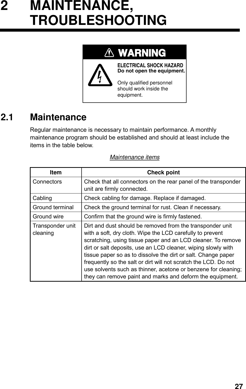
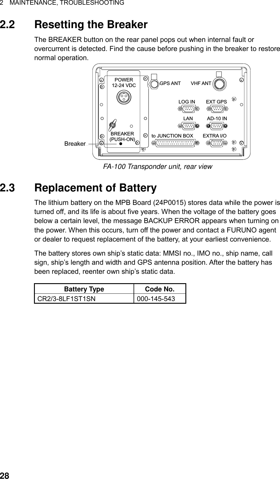
![2 MAINTENANCE, TROUBLESHOOTING 292.4 Troubleshooting The troubleshooting table below provides common symptoms of trouble and the means to rectify them. If you cannot restore normal operation, do not attempt to check inside the equipment. Refer any repair work to a qualified technician. Troubleshooting Symptom Remedy Power Cannot turn on the power. • Check that the power connector is firmly fastened.• Check if the breaker (red button) on the rear panel of the transponder unit has popped out. Find out the cause before pushing in the breaker to restore normal operation. • Check the power supply. Transmitting, receiving messages Cannot transmit or receive. • Check that the VHF antenna cable is firmly fastened. • Check the VHF antenna. • For TX message, try different TX channel (operating sequence: [MENU], [4], [1], [1]). Can transmit but message is sent to wrong party. • On the SET MSG TYPE sub-menu, check that ADDRESS TYPE is selected to ADDRESS-CAST and MMSI is correct, before sending a message. (operating sequence: [MENU], [4], [1], [1]) Position data No position data • Check the GPS antenna for damage. • Check the GPS antenna cable and its connectors.](https://usermanual.wiki/Furuno-USA/9ZWFA100.OPERATORS-MANUAL/User-Guide-275594-Page-39.png)
![2 MAINTENANCE, TROUBLESHOOTING 302.5 Diagnostics The FA-100 provides diagnostic tests to check program no., memory, keyboard, LCD and built-in GPS receiver. 2.5.1 Displaying program number 1. Press the [MENU] key to open the main menu. 2. Press the [7] key to open the DIAGNOSTICS sub-menu. [DIAGNOSTICS] 1 PROGRAM NO. 2 MEMORY TEST 3 KEY TEST 4 LCD TEST 5 ON/OFF HISTORY 6 GPS TEST 7 FOR SERVICEFor service technician.Not accessible by user. DIAGNOSTICS sub-menu 3. Press the [1] key to choose PROGRAM NO. [PROGRAM NO.]MAIN: 245-0001-0**SUB : 245-0002-0**H8S1: 245-0003-0**H8S2: 245-0004-0**H8S3: 245-0005-0**** = Program version no. PROGRAM NO. display 4. Press the [MENU] key to return to the DIAGNOSTICS sub-menu.](https://usermanual.wiki/Furuno-USA/9ZWFA100.OPERATORS-MANUAL/User-Guide-275594-Page-40.png)
![2 MAINTENANCE, TROUBLESHOOTING 312.5.2 Memory test The memory can be checked for proper operation as follows: 1. Press the [MENU] key to open the main menu. 2. Press the [7] key to open the DIAGNOSTICS sub-menu. 3. Press the [2] key to choose MEMORY TEST to test the memory. The results are shown as OK or NG (No Good). For any NG, contact your dealer for advice. [MEMORY TEST] ROM RAMMAIN : OK OKSUB : OK OKH8S1 : OK OKH8S2 : OK OKH8S3 : OK OK MEMORY TEST display 4. Press the [MENU] key to return to the DIAGNOSTICS sub-menu. 2.5.3 Keyboard test The keyboard can be checked for proper operation as follows: 1. Press the [MENU] key to open the main menu. 2. Press the [7] key to open the DIAGNOSTICS sub-menu. 3. Press the [3] key to choose KEY TEST. [KEY TEST] 147NXTCLR2580SFT369MENENT ESC : [MENU]x3 KEY TEST display 4. Press each key (except the [POWER] key) one by one. A key’s on-screen location fills in black while the key is pressed, if the key is functioning properly. 5. To escape from the keyboard test, press the [MENU] key three times.](https://usermanual.wiki/Furuno-USA/9ZWFA100.OPERATORS-MANUAL/User-Guide-275594-Page-41.png)
![2 MAINTENANCE, TROUBLESHOOTING 322.5.4 LCD test The LCD can be checked for proper display as follows: 1. Press the [MENU] key to open the main menu. 2. Press the [7] key to open the DIAGNOSTICS sub-menu. 3. Press the [4] key to choose LCD TEST. The screen color automatically changes from yellowish-green to black alternately if the LCD is normal. [LCD TEST] [LCD TEST] Yellowish-green Black LCD TEST display 4. Press the [MENU] key to return to the DIAGNOSTICS sub-menu. 2.5.5 On/off history The ON/OFF HISTORY log shows the date and time of the latest 30 power-ons and power-offs. In special cases, on and off times of 0 W transmission may also be shown. 1. Press the [MENU] key to open the main menu. 2. Press the [7] key to open the DIAGNOSTICS sub-menu. 3. Press the [5] key to choose ON/OFF HISTORY. [ON/OFF HISTORY]PWR-ON 17/MAY/200205:35:54PWR-OFF 17/MAY/200204:56:57PWR-ON 17/MAY/200204:06:34 Power turned on 17 May 2002at 05:35:54 ON/OFF HISTORY log 4. Use the [▼] or [▲] key to scroll the log. 5. Press the [MENU] key to return to the DIAGNOSTICS sub-menu.](https://usermanual.wiki/Furuno-USA/9ZWFA100.OPERATORS-MANUAL/User-Guide-275594-Page-42.png)
![2 MAINTENANCE, TROUBLESHOOTING 332.5.6 GPS test The GPS test checks the built-in GPS receiver for proper operation. 1. Press the [MENU] key to open the main menu. 2. Press the [7] key to open the DIAGNOSTICS sub-menu. 3. Press the [6] key to choose GPS TEST. [GPS TEST] START OF TEST PUSH [ENT] GPS TEST display 4. Press the [ENT] key to start the test. “NOW TESTING…” is displayed during the testing and the results are displayed as shown in the illustration below. SELF TEST1 shows OK for normal operation; NG (No Good) for abnormal operation. SELF TEST shows “0” for normal operation; other numeric for abnormal operation. [GPS TEST]PROGRAM No. : 4850218PROGRAM Ver. : 0**SELF TEST1 : OKSELF TEST2 : 0 ERROR CONTENTS** = Program Version No. GPS test results 5. Press the [MENU] key to return to the DIAGNOSTICS sub-menu.](https://usermanual.wiki/Furuno-USA/9ZWFA100.OPERATORS-MANUAL/User-Guide-275594-Page-43.png)
![2 MAINTENANCE, TROUBLESHOOTING 342.6 Alarm Status The alarm status log shows the date and time alarms were violated. 1. Press the [MENU] key to open the main menu. 2. Press the [3] key to choose OWN DATA. 3. Press the [3] key to choose ALARM STATUS. [ALARM STATUS]EPFS 7/MAR 4:32:16L/L 7/MAR 4:02:01SOG 7/MAR 2:34:54COG 6/MAR 7:09:32HDG 3/MAR 8:00:21ROT 19/FEB 9:05:22Alarm name,date and timeof alarm ALARM STATUS display 4. Use the [▼] or [▲] key to scroll the log. 5. Press the [MENU] key to close the log. Alarm statuses and their meanings Alarm Status Indication Alarm Message Meaning TX Tx malfunction TX malfunction ANT Antenna VSWR exceed limit Antenna VSWR trouble. Continued operation possible. CH1 Rx channel 1 malfunction TDMA RX1Board trouble. TX stopped on corresponding TX channel. CH2 Rx channel 2 malfunction TDMA RX2 Board trouble. TX stopped on corresponding TX channel. CH70 Rx channel 70 malfunction DSC RX Board trouble, transmission stopped on CH70. EPFS External EPFS lost No data from external navigator. Continued operation possible. L/L No sensor positioning in use No L/L data SOG No valid SOG information Invalid SOG data COG No valid COG information Invalid COG data HDG Heading lost/invalid Invalid/nonexistent HDG data ROT No valid ROT information Invalid ROT data](https://usermanual.wiki/Furuno-USA/9ZWFA100.OPERATORS-MANUAL/User-Guide-275594-Page-44.png)
![2 MAINTENANCE, TROUBLESHOOTING 36Note: Detection of RX Malfunction 1) Detection of TDMA RX malfunction Frequency error PLL chip on receiver board generates lock or unlock signal for synthesizer. MPU watches and sets status flag which reflects data of ALR sentence. ID 003 for RX1, ID 004 for RX2 2) Detection of DSC RX malfunction General error DSC Error (ID: 005) will happen in case of DSC MPU could not receive format specifier of the data from DSC amplifier unless RSSI exists more than four seconds. 2.8 GPS Monitor The GPS monitor display shows information about the built-in GPS receiver, including position, speed over ground, course over ground, date, time, mode and status. 1. Press the [MENU] key to open the menu. 2. Press the [3] key to choose OWN DATA. 3. Press the [5] key to choose INTERNAL GPS. [INTERNAL GPS]LAT : 34 44.4639’NLON : 135 21.2395’ESOG : 10.9 ktCOG : 98.9 degUTC : 6/MAR/2002 6:29:02MODE: A STS: 3DLatitude positionLongitude positionSpeed over groundCourse over groundDateTimeModeA: GPSD: DifferentialN: No FixSTS (Status)2D:2D GPS position fix3D: 3D GPS position fixD2D: 2D DGPS position fixD3D: 3D DGPS position fixDOP: HDOP larger than 4 in 2D fix, or PDOP larger than 6 in 3D fixNO FIX: No position fix Internal GPS monitor 5. Press the [MENU] key to close the display.](https://usermanual.wiki/Furuno-USA/9ZWFA100.OPERATORS-MANUAL/User-Guide-275594-Page-46.png)
![2 MAINTENANCE, TROUBLESHOOTING 372.9 Displaying Sensor Status The SENSOR STATUS display monitors sensor status. 1. Press the [MENU] key. 2. Press the [3] key to choose OWN DATA. 3. Press the [4] key to choose SENSOR STATUS. [SENSOR STATUS] UTC CLOCK LOST Sensor status display 4. Press the [MENU] key to close the menu.](https://usermanual.wiki/Furuno-USA/9ZWFA100.OPERATORS-MANUAL/User-Guide-275594-Page-47.png)
![2 MAINTENANCE, TROUBLESHOOTING 382.10 Restoring Default Settings You may clear all settings to start afresh with default settings. When this is done, the default options for all items in the INIT SETTING and SYSTEM SETTINGS sub-menus are restored. GPS data is also cleared; however, MMSI and IMO numbers are not cleared. 1. Turn on the power while pressing and holding down the [CLR/ALM] key. Hold down the [CLR/ALM] key until the “SHUT DOWN” screen below appears. SHUT DOWN18/MAR/200212:12:11 Shut down screen 2. The equipment then starts restoring default settings, showing “COMPLETE” when finished. NOW STARTING . . .CHECKING MENORYCOMPLETE Screen after memory has been cleared 3. Press the [CLR/ALM] key. The plotter display appears. 4. Set items in INIT SETTINGS and SYSTEM SETTINGS, referring to Chapter 1.](https://usermanual.wiki/Furuno-USA/9ZWFA100.OPERATORS-MANUAL/User-Guide-275594-Page-48.png)
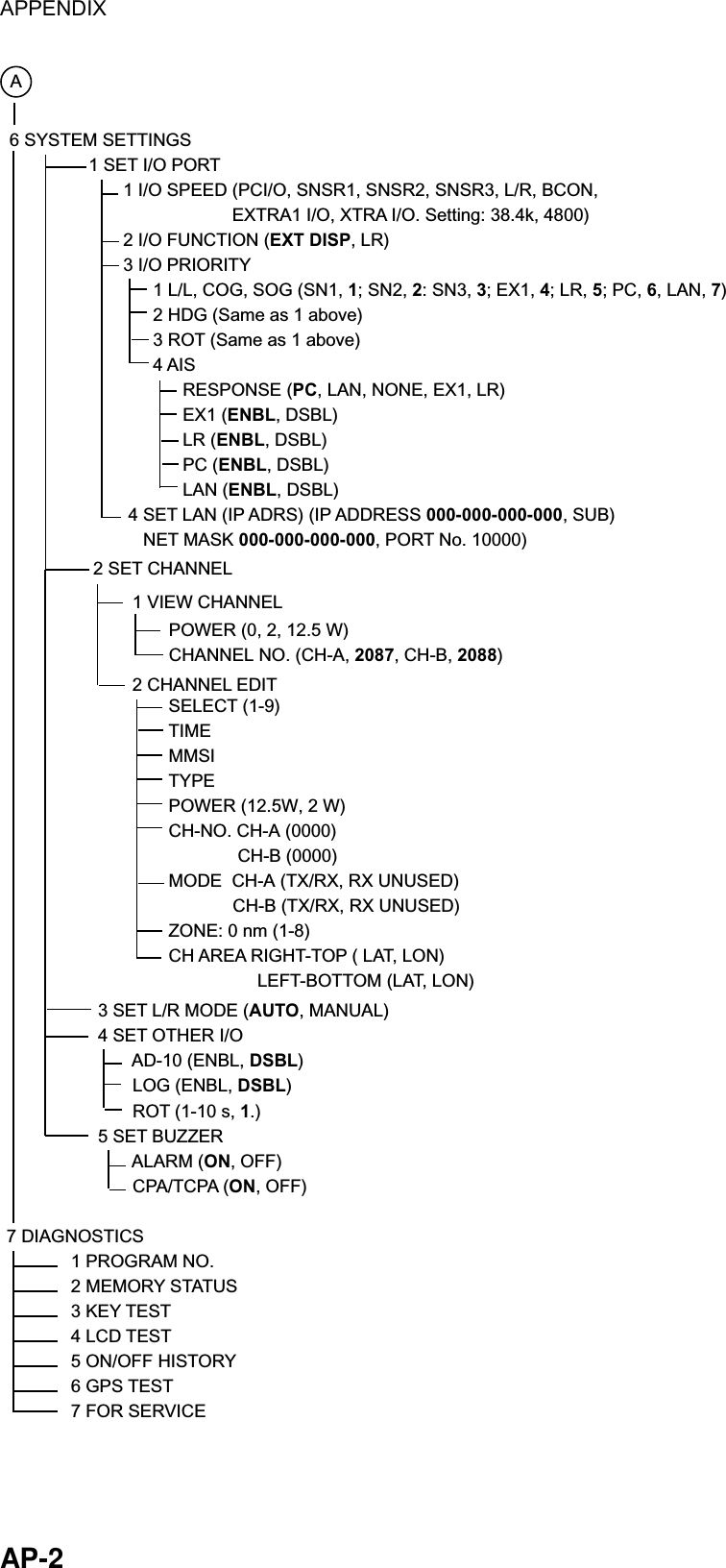
![AP-1 APPENDIX Menu Tree Default settings in bold italics. 1 TARGET DATA 2 PLOTTER 3 OWN DATA 1 OWN STATIC DATA OWN STATIC DATA 1 (Name, call sign, MMSI, IMO no.) OWN STATIC DATA 2 (Destination, estimated date and time of arrival) OWN STATIC DATA 3 (DTE, nav status) OWN STATIC DATA 4 (CPA, TCPA, GPS antenna position) OWN STATIC DATA 5 (Crew, type, class) 2 OWN DYNAMIC DATA (Own ship latitude, longitude, SOG, COG, ROT, HDG) 3 ALARM STATUS (Displays alarm log.) 4 SENSOR STATUS 5 INTERNAL GPS (Shows position, SOG, COG, time, date, mode, reveiver status.) 4 SET MSG 1 CREATE MSG 1 SET MSG TYPE ADDRESS TYPE (ADDRESS-CAST, BROADCAST) MMSI MSG TYPE (NORMAL, SAFETY) CHANNEL (CH-A, CH-B, A OR B) 2 SET MSG 3 SEND MSG 2 XMIT MSG(S) 3 RCVD MSG(S) 5 INIT SETTINGS 1 SET SHIP DATA (NAME, CALL SIGN, DRAUGHT, DTE) 2 SET DESTINATION (DATE, TIME, DESTINATION) 3 SET NAV STATUS 4 SET TYPE&CREW CREW (0-8191, 0) TYPE CLASS (A, B) TYPE NO. (Set ship type. See page 8.)5 SET CPA/TCPA CPA (0-6.00 nm) TCPA (0-60 min) ACTV (ENBL, DSBL)6 SET ANTENNA POS 1 INTERNAL ANT POS A (0-511 m, 0) B (0-511 m, 0) C (0-63 m, 0) D (0-63 m, 0) 2 EXTERNAL ANT POS (Same items as 1 INTERNAL ANT POS.)[MENU] key(Continued on next page.)](https://usermanual.wiki/Furuno-USA/9ZWFA100.OPERATORS-MANUAL/User-Guide-275594-Page-49.png)