Furuno USA 9ZWRTR051 MARINE RADAR User Manual OPERATORS MANUAL PART 4
Furuno USA Inc MARINE RADAR OPERATORS MANUAL PART 4
Contents
- 1. OPERATORS MANUAL PART 1
- 2. OPERATORS MANUAL PART2
- 3. OPERATORS MANUAL PART3
- 4. OPERATORS MANUAL PART 4
OPERATORS MANUAL PART 4
5-1
5. CUSTOMIZING YOUR UNIT
This chapter describes the various options which allow you to set up your unit to
suit your needs.
5.1 Generic Setup
This paragraph shows you how to set up functions common to the plotter, radar
and sounder displays, on the GENERAL SETUP menu, which you may display
from any mode. These items include data, position and time formats, units of
measurement, data sources, etc.
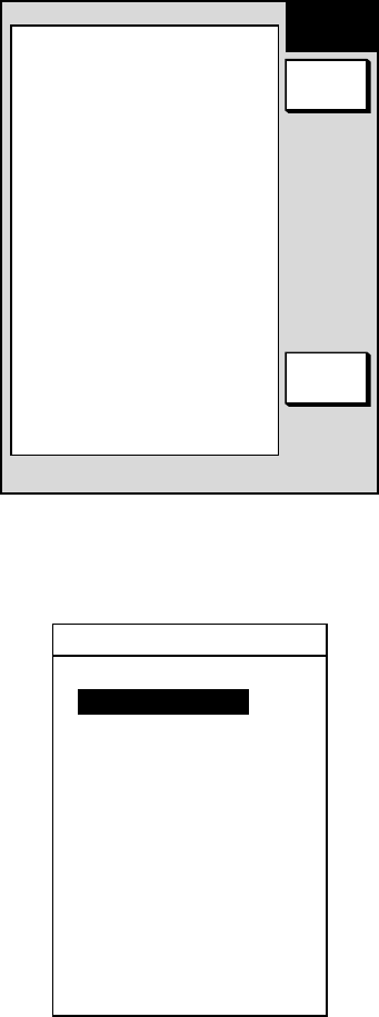
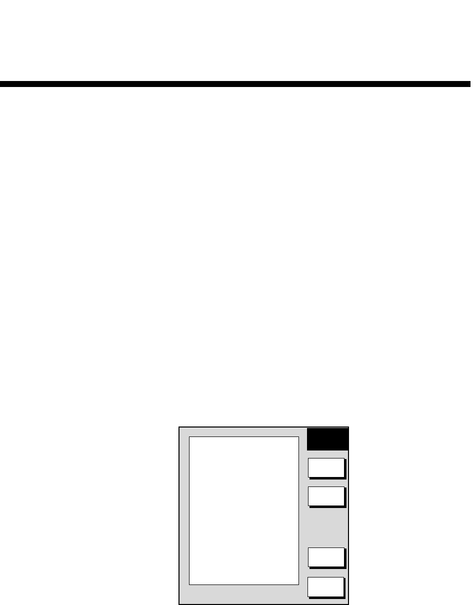
1. Show the plotter display and press the [MENU] key to display the main menu.
2. Press the SYSTEM CONFIGURATION soft key.
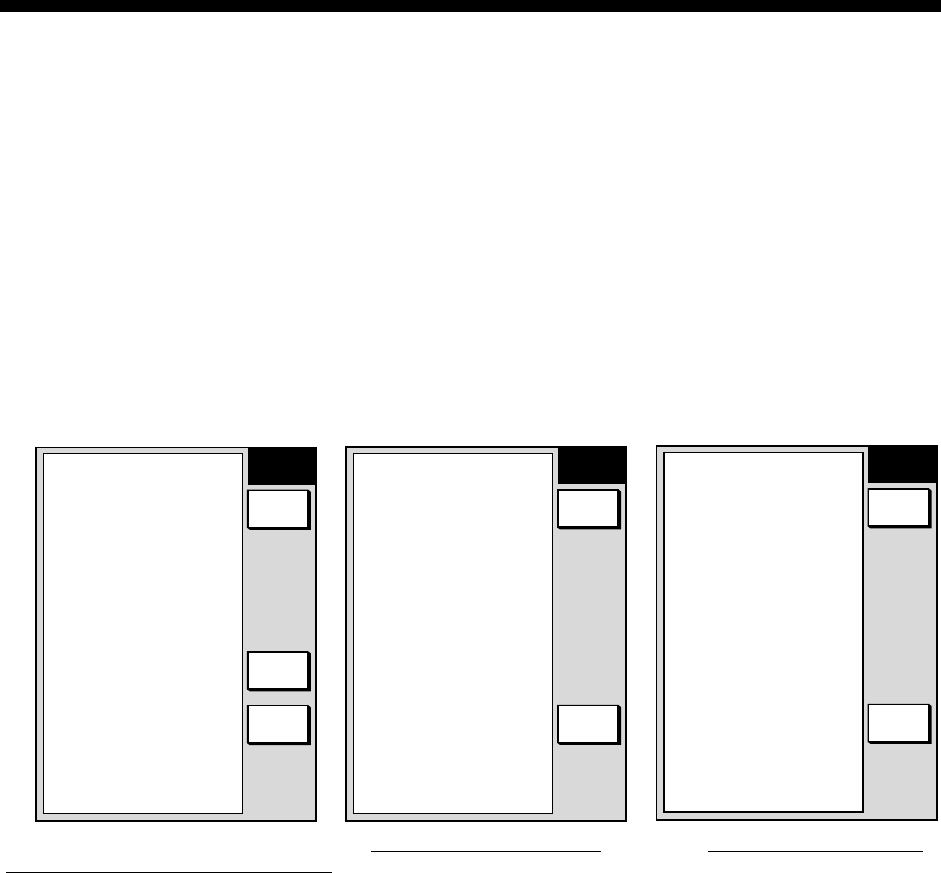
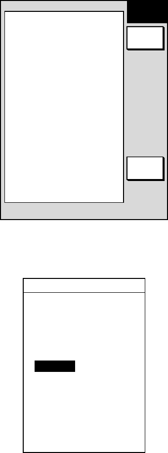
3. Press the GENERAL SETUP soft key.
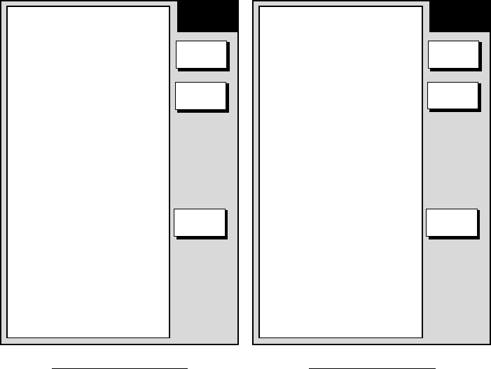
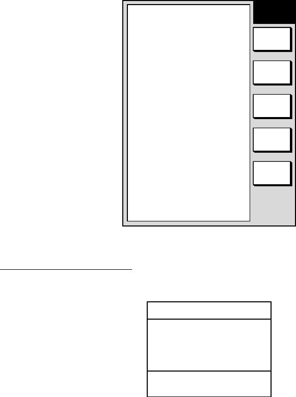
GENERAL
SETUP 1
RETURN
NEXT
PAGE
EDIT
KEY BEEP
ON
LANGUAGE
ENGLISH
RANGE/SPEED UNIT
nm, kt
TEMP UNIT
°C
DEPTH UNIT
ft
TEMP SOURCE
NMEA
DEPTH SOURCE
NMEA
RESET TRIP LOG
NO
▲
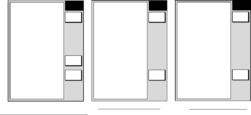
Page 1
(MODEL-1700C series, MODEL-1700 series)
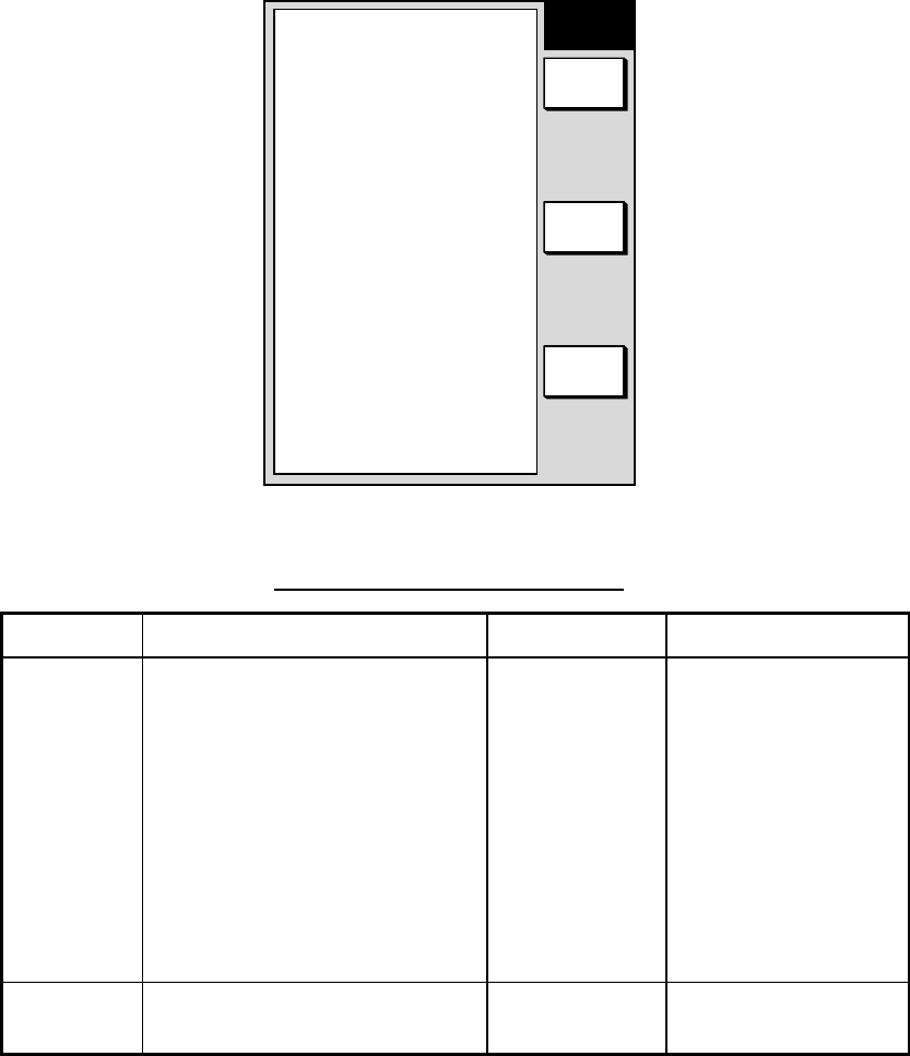
PREV.
PAGE
GENERAL
SETUP 2
EDIT
LAT/LON DISPLAY
DD° MM.MMM'
TD DISPLAY
LC
SPEED DISPLAY
SOG
POSITION DISPLAY
LAT&LON
TIME DISPLAY
24hours
I/R REMOTE MODE
A
RANGE, BEARING MODE
RHUMB LINE
BEARING
MAGNETIC
MAG VARIATION
AUTO 7.0° W
▲
Page 2 (MODEL-1700C series)
PREV.
PAGE
GENERAL
SETUP 2
EDIT
LAT/LON DISPLAY
DD° MM.MMM'
TD DISPLAY
LC
SPEED DISPLAY
SOG
POSITION DISPLAY
LAT&LON
TIME DISPLAY
24hours
I/R REMOTE MODE
A
RANGE, BEARING MODE
RHUMB LINE
BEARING
MAGNETIC
MAG VARIATION
AUTO 7.0° W
DISPLAY MODE
NORMAL
▲
Page 2 (MODEL-1700 series)
General setup menu
4. Press the NEXT PAGE or PREV. PAGE soft key to switch pages if necessary.
5. Use the cursor pad to select item.
6. Press the EDIT soft key.
7. Use the cursor pad to select option desired.
8. Press the RETURN soft key.
9. Press the [MENU] key to close the menu.

5. CUSTOMIZING YOUR UNIT
5-2
Contents of general menu
Item Description Settings Default Settings
Key Beep Turns key operation beep on/off. On, Off On
Language Chooses menu language. English, French, German,
Italian, Portuguese, Spanish English
Range/Speed
Unit Chooses unit of range and speed
measurement. nm, kt; km, km/h; sm,
mph; nm & yd, kt, nm & m,
kt; km & m, km/h, sm & yd,
mph
nm, kt
Temp Unit Chooses unit of water temperature
measurement. °C, °F°F
Depth Unit Chooses unit of depth measurement. ft, m, fa PB (Passi/Braza) Ft
Temp Source Chooses source of water temperature data. ETR (blackbox transducer),
NMEA NMEA
Depth Source Chooses source of depth data. ETR, NMEA NMEA
Reset Trip Log Resets distance run. Yes, No No
Lat&Lon
Display Chooses how many digits (or seconds) to
display after decimal point in latitude and
longitude position.
DD°MM.MM’,
DD°MM.MMM’,
DD°MM.MMMM’,
DD°MM’SS.S”
DD°MM.MMMM’
TD Display Chooses TD type. Loran C, Decca Loran C
Speed Display Chooses speed measurement method to use;
speed-over-ground or speed-thru-water. SOG, STW SOG
Position Display Shows position in LAT/LON or TD. LAT/LON, TD LAT/LON
Time Display Chooses time notation. 12 hours, 24 hours 24 hours
I/R Remote
Mode Chooses remote controller mode. A, B, C, D A
Bearing Mode A navigation device outputs both true and
magnetic bearings. A magnetic bearing is true
bearing plus (or minus) earth’s magnetic
deviation. Thus the equation for finding
magnetic bearing is;
true bearing ± x (magnetic variation) =
magnetic bearing
True, Magnetic Magnetic
Mag Variation The magnetic variations for all areas of the
earth are preprogrammed into this unit. The
preprogrammed variation is accurate for most
instances, however you may wish to manually
enter a variation. For manual input, select
Manual, hit the EDIT soft key, enter value and
hit the RETURN soft key to finish.
Auto, Manual Auto
Display Mode
(MODEL-1700
series)
Reverses background (black) and foreground
(white) colors. Normal, Reverse Normal
5. CUSTOMIZING YOUR UNIT
5-3
5.2 Plotter Setup
This paragraph provides the information necessary for setting up the plotter
display. Be sure to show the plotter display before executing any procedure.
5.2.1 Navigation options
Navigation options, for example, waypoint switching method, may be set on the
plotter setup menu.
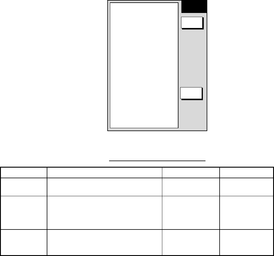
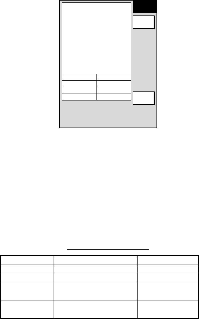
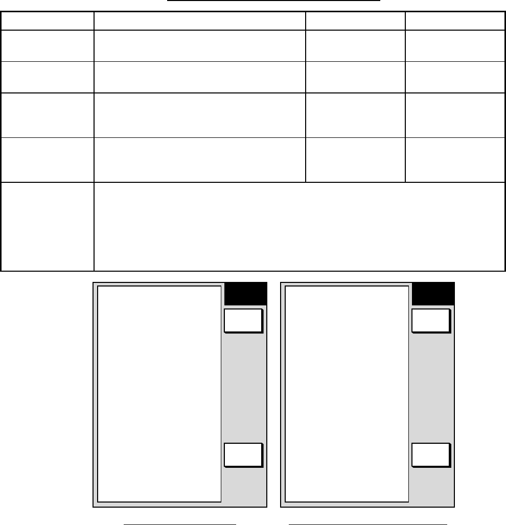
1. Show the plotter display and press the [MENU] key open the main menu.
2. Press the PLOTTER SETUP soft key.
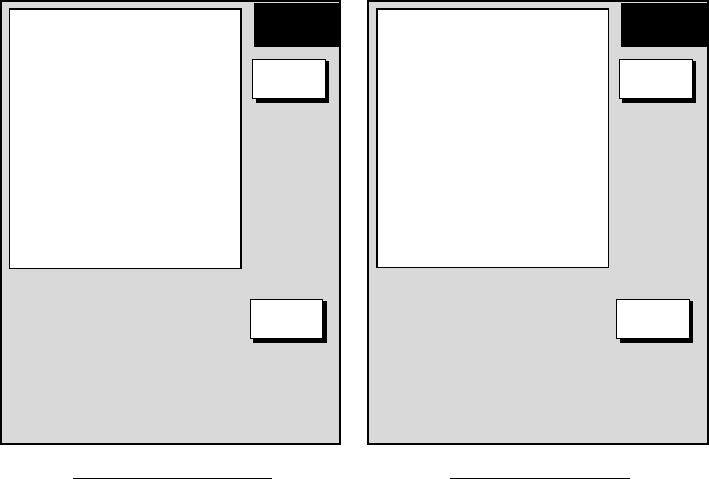
WAYPOINT SWITCHING
AUTO 2
COURSE VECTOR
LINE
SET GO TO METHOD
1 POINT
▲
PLOTTER
SETUP
EDIT
RETURN
Display option menu
Contents of display option menu
Item Description Settings Default Setting
Waypoints
Switching Chooses waypoint switching method. See
“switching waypoints” on page 2-28. Auto 1, Auto 2,
Manual Auto
Course Vector You may extend a line from the own ship
position to show ship’s course. It may be a
vector (length depends on ship’s speed) or a
simple line (course bar)
Line, Vector, Off Line
Set Go to
Method Sets the method by which to navigate to a
quick point. See paragraph “2.12.1 Navigating
to a quick point.”
1 Point, 35 Points, 35
Points & Port Service 1 Point
5. CUSTOMIZING YOUR UNIT
5-4
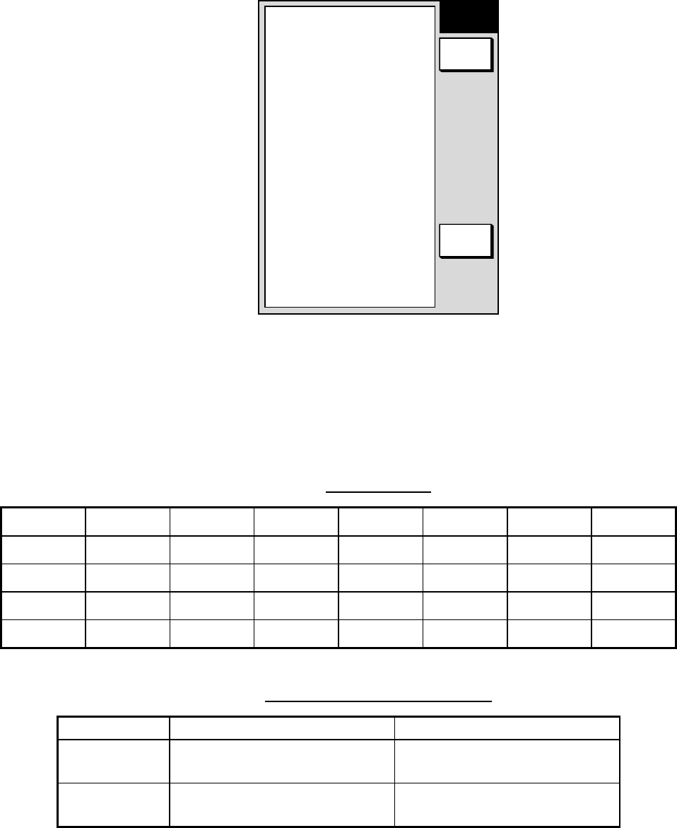
5.2.2 Soft key setup
The soft keys, shown when the soft keys are turned off, provide one-touch call up
of a desired function.
If the above settings are not to your liking you may change them as follows:
1. Press the [MENU] key.
2. Press the SOFT KEY SETUP soft key.
FUNC
KEY
RETURN
EDIT
SOFT KEY1
ADD NEW WAYPOINT A
D
D
SOFT KEY2
MOVE WAYPOINT M
W
P
SOFT KEY3
START/STOP TRACK T
R
K
SOFT KEY4
ALPHANUMERIC LIST A
L
P
SOFT KEY5
DATA BOX ON/OFF D
B
X
▲
Soft key setup menu (plotter)
3. Select the function key (soft key) you want to program and press the EDIT soft
key. A menu shows the functions available and the current selection is
highlighted.
FUNCTION
OFF
ADD NEW WAYPOINT
MOVE WAYPOINT
RULER
GO TO WAYPOINT
GO TO ROUTE
EDIT MARK&LINE
START/STOP TRACK
TTM ON/OFF
ERASE TTM TRACK
ALPHANUMERIC LIST
LOCAL LIST
ROUT LIST
CHANGE CONTROL
DATA BOX ON/OFF
Soft key menu (plotter)
4. Select function desired and press the ENTER soft key or the [ENTER] knob.
See the table below for description of each function.
5. Press the [MENU] key to close the menu.

5. CUSTOMIZING YOUR UNIT
5-5
Plotter soft keys
Function Action Function Key Label
NO FUNCTION Assigns no function.
ADD NEW WAYPOINT Enters new waypoint, at cursor position. ADD
MOVE WAYPOINT Moves selected waypoint to different position. MWP
RULER Measures range and bearing between two
targets. RUL
GO TO WAYPOINT Specify waypoint to set as destination. GTW
GO TO ROUTE Specify route to follow. GRT
EDIT MARK & LINE Displays mark & line menu. EML
START/STOP TRACK Starts/stops recording of own ship track. TRK
TTM ON/OFF Turns TTM (target track) display on/off. TTM
ERASE TTM TRACK Erases TTM track. ETT
ALPHANUMERIC LIST Displays waypoint alphanumeric list. ALP
LOCAL LIST Displays waypoint local list. LCL
ROUTE LIST Displays route list. RTE
CHANGE CONTROL Changes control in combination screen. CHG
DATA BOX ON/OFF Shows/hides data boxes. DBX
5. CUSTOMIZING YOUR UNIT
5-6
5.3 Chart Setup
This paragraph shows you how to setup digital charts, from offsetting chart
position to turning chart attributes on or off.
5.3.1 Chart offset
In some instances position may be off by a few minutes. For example, the
position of the ship is shown to be at sea while it is in fact moored at a pier. You
can compensate for this error by offsetting chart position as shown in the
procedure below. You can execute the procedure from any display mode.
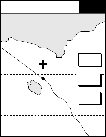
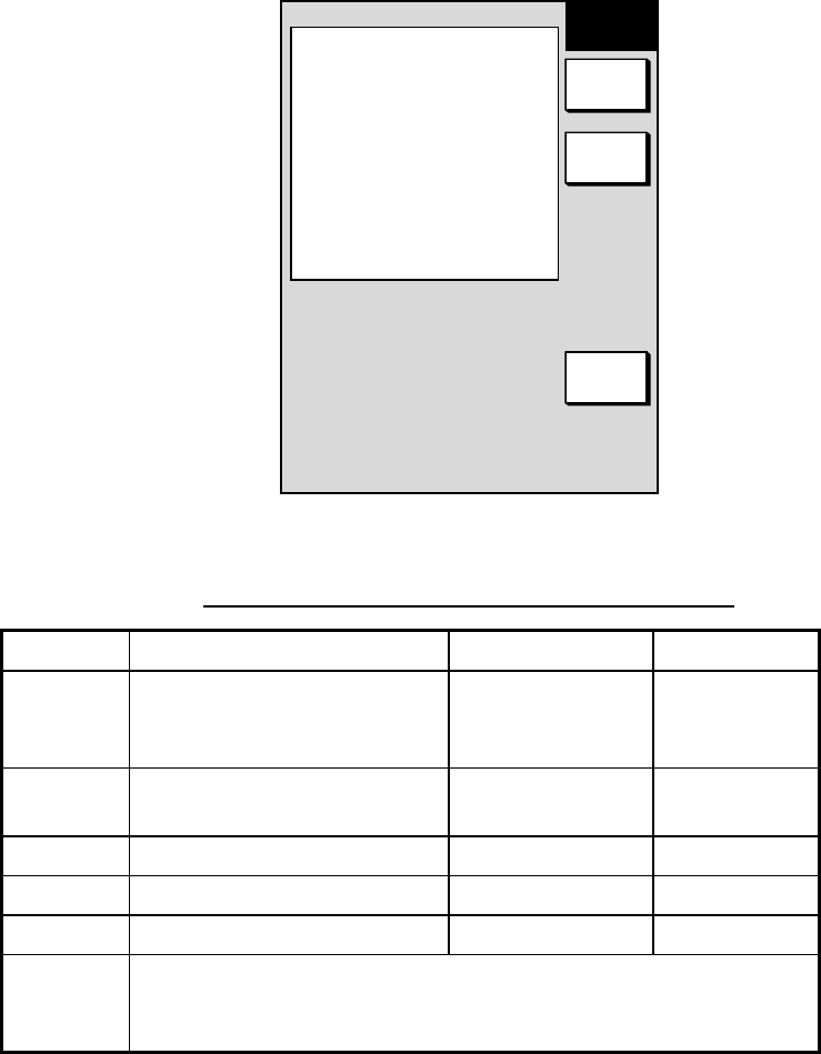
1. Show the plotter display and press the [MENU] key followed by the CHART
SETUP and CHART OFFSET soft keys.
34 24. 3456 N 359.9
124 24. 3456 W 59.9kt 1
+CHART
OFFSET
SET
OFFSET
RESET
OFFSET
RETURN
Plotter display, chart offset selected
2. Use the Omnipad to place the cursor at correct latitude and longitude position.
3. Press the SET OFFSET soft key.
4. Press the RETURN soft key to finish.
5. Press the [MENU] key to close the menu.
To cancel chart offset, press the RESET OFFSET soft key at step 3 in the above
procedure.
5. CUSTOMIZING YOUR UNIT
5-7
5.3.2 FURUNO, Nav-Charts™ chart attributes
Charts attributes may be turned on or off from the chart details menu, which you
may display pressing the [MENU] key followed by the CHART SETUP and
CHART DETAILS soft keys.
LAT LON GRID
ON
TEXT INFO
ON
WAYPOINT
LARGE
WAYPOINT NAME
ON
CHART BORDER LINES
ON
LANDMASS
ON
NAV AIDS
ON
SECTOR INFO
ON
OTHER SYMBOL
ON
MARK SIZE
NORMAL
▲
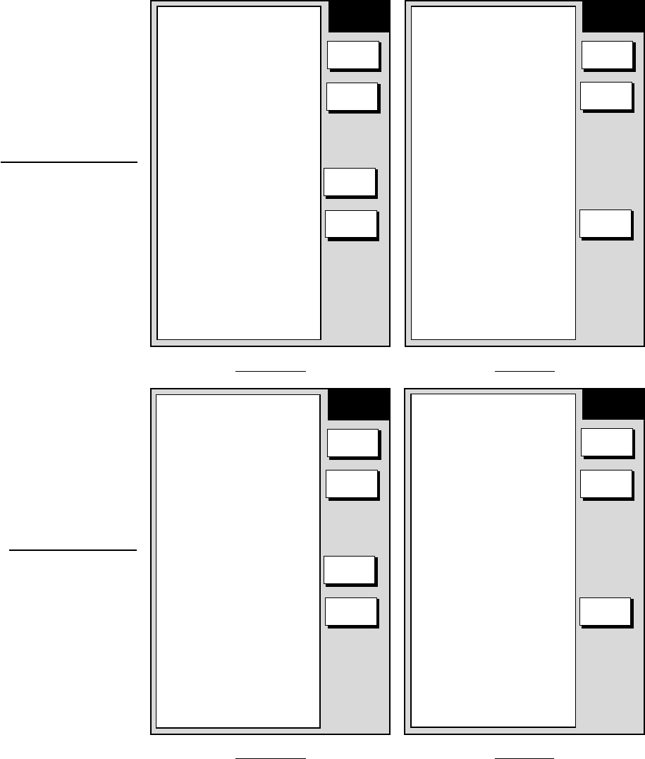
MODEL-1700 series
LAT LON GRID
GREEN
TEXT INFO
ON
WAYPOINT
LARGE
WAYPOINT NAME
ON
CHART BORDER LINES
ON
LANDMASS
BRT YELLOW
BACKGROUND
BLUE
NAV AIDS
ON
SECTOR INFO
ON
OTHER SYMBOL
WHITE
MARK SIZE
NORMAL
▲
MODEL-1700C series
CHART
DETAILS
EDIT
DEPTH
INFO
RETURN
CHART
DETAILS
EDIT
DEPTH
INFO
RETURN
Chart details menu (FURUNO, Nav-Charts™)

5. CUSTOMIZING YOUR UNIT
5-8
Contents of chart details menu
Settings, Default Setting Settings, Default Setting
Item Description MODEL-1700C series MODEL-1700 series
Lat&Lon Grid Latitude and
longitude grids On: Red, yellow,
green, light-blue,
purple, blue,
white.
Off
On, Green On, Off On
Text Info Geographic
place, name On, Off On On, Off On
Waypoint Waypoint size Large, Small, Off Large Large, Small,
Off Large
Waypoint Name Waypoint name On, Off On On, Off On
Index Chart indices On, Off On On, Off On
Landmass Landmass
brilliance Brt, Dim: Red,
yellow, green,
light-blue, purple,
blue, white.
Off
Brt, Yellow Brt, Dim, Off Brt
Background Chart
background color Blue, Black Black Not shown on GD-1700C.
Nav Aids Navaid data on
Nav-Charts™;
lighthouse data
on FURUNO
charts
On, Off On On, Off On
Sector Info Lighthouse
viewing sector on
FURUNO charts
On, Off On On, Off On
Other Symbol Other map
symbols On: Red, yellow,
green, light-blue,
purple, blue,
white.
Off
On, White On, Off On
Mark Size Mark size Normal, Small Normal Normal, Small Normal
< 10 m On, Off On, Red On, Off On
10 m On, Off On, Yellow On, Off On
> 10 m On, Off On, Blue On, Off On
Depth Info (soft
key)
(Depth contours
for depths at
right)* Depth Info On, Off On On, Off On
* = Depth contour for MODEL-1700C series available in, red, yellow, green, light-
blue, purple, blue, and white.
5. CUSTOMIZING YOUR UNIT
5-9
DEPTH < 10m
ON
DEPTH = 10m
ON
DEPTH > 10m
ON
DEPTH INFO
ON
10m: APPROX. 30ft OR 5fa
OR 6pb
▲
MODEL-1700 series
DEPTH < 10m
RED
DEPTH = 10m
YELLOW
DEPTH > 10m
BLUE
DEPTH INFO
RED
10m: APPROX. 30ft OR 5fa
OR 6pb
▲
MODEL-1700C series
DEPTH
INFO
EDIT
RETURN
DEPTH
INFO
EDIT
RETURN
Depth info menu (FURUNO, Nav-Charts™)
5. CUSTOMIZING YOUR UNIT
5-10
5.3.3 C-MAP chart attributes
Charts attributes may be turned on or off from the chart details menu, which you
may display pressing the [MENU] key followed by the CHART SETUP and
CHART DETAILS soft keys.
▲
Page 2
▲
Page 1
CHART
DETAILS
EDIT
DEPTH
INFO
RETURN
CHART
DETAILS
EDIT
DEPTH
INFO
PREV.
PAGE
NAMES
PLOT & OVERLAY
COMPASS
PLOT & OVERLAY
TIDE & CURRENTS
PLOT & OVERLAY
NATURAL FEATURES
PLOT& OVERLAY
RIVER & LAKE
PLOT & OVERLAY
PCULTURAL FEATURES
PLOT & OVERLAY
LANDMARKS
PLOT & OVERLAY
CHART GENERATION
PLOT & OVERLAY
NEW OBJECT
PLOT
COMPLEX OBJECT IOCON
MULTIPLE
INFORMATION LEVEL
DETAILED
NEXT
PAGE
MODEL-1700C series
▲
Page 2
▲
Page 1
CHART
DETAILS
EDIT
DEPTH
INFO
RETURN
CHART
DETAILS
EDIT
DEPTH
INFO
PREV.
PAGE
NEXT
PAGE
MODEL-1700 series
WAYPOINT NAME
PLOT & OVERLAY
LAT/LON GRID
PLOT & OVERLAY
CHART BOARDER LINES
PLOT & OVERLAY
BACKGROUND COLOR
WHITE
PORTS & SERVICES
PLOT
ATTENTION AREAS
PLOT & OVERLAY
NAV LANES
PLOT
LIGHTS
PLOT & OVERLAY
BUOYS & BEACON
PLOT & OVERLAY
SIGNALS
PLOT & OVERLAY
CARTOGRAPHIC OBJECT
PLOT
WAYPOINTS
ON
NAMES
PLOT & OVERLAY
COMPASS
PLOT & OVERLAY
TIDE & CURRENTS
PLOT & OVERLAY
NATURAL FEATURES
PLOT& OVERLAY
RIVER & LAKE
PLOT & OVERLAY
PCULTURAL FEATURES
PLOT & OVERLAY
LANDMARKS
PLOT & OVERLAY
CHART GENERATION
PLOT & OVERLAY
NEW OBJECT
PLOT
COMPLEX OBJECT IOCON
MULTIPLE
INFORMATION LEVEL
DETAILED
WAYPOINT NAME
ON
LAT/LON GRID
ON
CHART BOARDER LINES
ON
PORTS & SERVICES
PLOT
ATTENTION AREAS
ON
NAV LANES
ON
LIGHTS
ON
BUOYS & BEACON
ON
SIGNALS
ON
CARTOGRAPHIC OBJECT
ON
WAYPOINTS
ON
Chart details menu (C-map)

5. CUSTOMIZING YOUR UNIT
5-11
Contents of chart details menu (C-map)
Settings Default Setting Settings Default Setting
Item Description MODEL-1700C series MODEL-1700 series
Waypoints Waypoint display Plot & Overlay,
Plot Only, Off Plot & Overlay On, Off On
Waypoint Name Waypoint name Plot & Overlay,
Plot Only, Off Plot & Overlay On, Off On
Lat&Lon Grid Latitude and
longitude grids Plot & Overlay,
Plot Only, Off Plot & Overlay On, Off On
Chart Border
Lines Chart indices Plot & Overlay,
Plot Only, Off Plot & Overlay On, Off On
Background
(MODEL-1700C
series only)
Chart
background color White, Black White Not shown on GD-1700C.
Ports & Services Port service icon
display Plot & Overlay,
Plot, Off Plot On, Off On
Attention Area Attention area
icon display Plot & Overlay
Contour, Plot,
Plot Contour, Off
Plot Contour On, Contour, Off Contour
Nav lanes Navigation lanes Plot & Overlay,
Plot, off Plot On, Off On
Lights Lighthouse icon,
sector Plot & Overlay
(no sector), Plot
(no sector), Off
Plot & Overlay On, No Sector,
Off On
Buoys &
Beacons Buoys, beacons
display Plot & Overlay,
Plot, Off Plot Overlay On, Off On
Signals Signals display Plot & Overlay,
Plot, Off Plot & Overlay On, Off On
Cartographic
Objects Cartographic
objects display Plot & Overlay,
Plot, Off Plot On, Off On
Names Names category
icon Plot & Overlay,
Plot, Off Plot & Overlay On, Off On
Compass Compass
category icons Plot & Overlay,
Plot, Off Plot & Overlay On, Off On
Tide & Current Tide display Plot & Overlay,
Plot, Off Plot & Overlay On, Off On
Natural Features Land outline Plot & Overlay,
Plot, Off Plot & Overlay On, Off On
River & Lake Rivers and lakes Plot & Overlay,
Plot, Off Plot & Overlay On, Off On
Cultural features Cultural features
icon Plot & Overlay,
Plot, Off Plot & Overlay On, Off On
Landmarks Landmarks
category icon Plot & Overlay,
Plot, Off Plot & Overlay On, Off On
(Continued on next page)

5. CUSTOMIZING YOUR UNIT
5-12
Contents of chart details menu (continued from previous page)
Settings Default Setting Settings Default Setting
Item Description MODEl-1700C series MODEL-1700 series
Chart Generation Chart generation
category icon Plot & Overlay,
Plot, Off Plot & Overlay On, Off On
New Object New object
category icon Plot & Overlay,
Plot, Off Plot & Overlay On, Off On
Complex Object
Icon Single or multiple
icon for object
composed of
several icons
Multiple, Single Multiple Multiple, Single Multiple
Information Level Basic or detailed
data for objects Basic, Detailed Detailed Basic, Detailed Detailed
Bathymetric lines Plot & Overlay,
Plot, Off Plot & Overlay On, Off On
Spot Soundings Plot & Overlay,
Plot, Off Plot & Overlay On, Off On
Bottom Type Plot & Overlay,
Plot, Off Plot & Overlay On, Off On
Depth Areas
Limit 0-48999ft
(15000m,
8202fa, 8972pb)
20,164ft (6, 50m,
3, 27 fa, 3, 30pb) 0-48999ft
(15000m,
8202fa, 8972pb)
33ft (10m, 6fa,
6pb)
Depth Info (soft
key)
See illustration
on next page
Bathymetric &
Sounding Range 0-48999ft
(15000m,
8202fa, 8972pb)
0-30ft (0-10m, 0-
6fa, 0-6pb) 0-48999ft
(15000m,
8202fa, 8972pb)
0-30ft (0-10m, 0-
6fa, 0-6pb)
Settings key
Basic: Shows basic characteristics of objects.
Contour: Shows only national boundary.
Detailed: Shows detailed characteristics of objects.
Multiple: Shows multiple icons for complex objects
Off: Turns item off.
On: Turns item on.
Plot: Shows item on plotter display:
Plot (no sector): Sector not shown on track display.
Plot Contour: Shows contour on track display.
Plot & Overlay: Shows item on plotter and overlay displays.
Plot & Overlay (no sector): Shows item on track and overlay displays. Sector not shown on
overlay.
Single: Shows single icon for complex objects..
5. CUSTOMIZING YOUR UNIT
5-13
▲
MODEL-1700 series
BATHYMETRIC LINES
PLOT
SPOT SOUNDINGS
PLOT OVERLAY
BOTTOM TYPE
PLOT
DEPTH AREAS LIMIT
33ft, 66ft
BATHYMETRIC &
SOUNDINGS RANGE
00000-00033ft
▲
MODEL-1700C series
DEPTH
INFO
EDIT
RETURN
DEPTH
INFO
EDIT
RETURN
BATHYMETRIC LINES
ON
SPOT SOUNDINGS
ON
BOTTOM TYPE
ON
DEPTH AREAS LIMIT
33ft
BATHYMETRIC &
SOUNDINGS RANGE
00000-00033ft
Depth info menu (C-map)
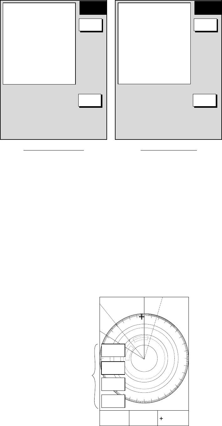
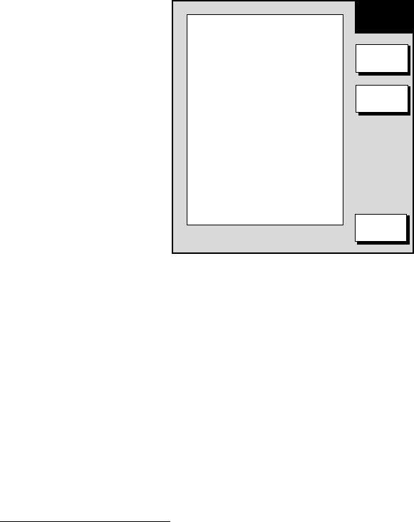
5.4 Data Boxes Setup
You may separately select the data to show in the data boxes for the plotter, radar
and sounder displays.
1. Display the plotter, radar or sounder display, whichever you want to set.
2. Press the [MENU] key to open the main menu.
3. Press one of the following sets of soft keys depending on the display selected
at step 1.
a) Plotter mode: PLOTTER OPTION, DATA BOX
b) Radar mode: RADAR DISPLAY, DATA BOX
c) Sounder mode: SOUNDER MENU, DATA BOX
17.0 R
8.2nm
E1
V1
E2 320.1 R 359.9 R
11.7nm
V2 10.9nm
12/
3nm
SP
HU
319. 9
R
TRAIL 30m
02m30s
G1 IN
G2 OUT
ES 2
IR L
NR
RNG
123.5 nm
SPEED
27.6kt
TRIP LOG
1022.5nm
DEPTH
276ft
Data boxes
Data box menu
5. CUSTOMIZING YOUR UNIT
5-14
4. Use the Omnipad to select an item and then press the EDIT soft key.
5. Select ON or OFF as desired.
6. Repeat steps 3 and 4 to turn other items on or off.
7. Press the RETURN soft key.
8. Press the [MENU] key to close the menu.
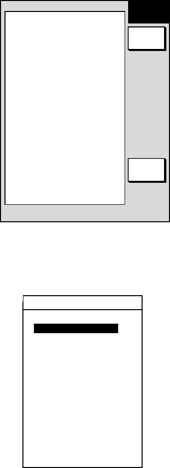
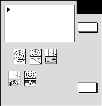
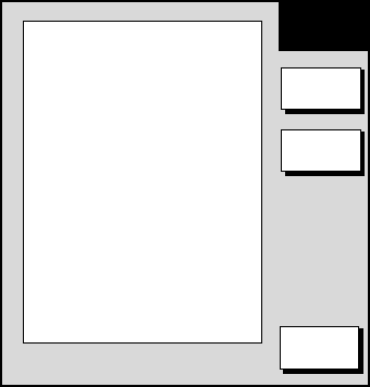
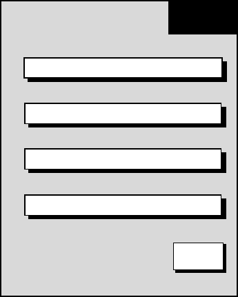
5.5 Hot Page Setup
On the full-screen selection window (see the figure at the top of the next page)
five useful combination screens are preset at factory as “PAGE 1-5.” The default
settings are
PAGE 1: Radar display
PAGE 2: Radar/plotter display
PAGE 3: Plotter/sounder display
PAGE 4: Plotter/compass display
PAGE 5: Plotter/highway display
If the default settings are not to your liking you may change them as follows:
1. Press the [MENU] key followed by pressing the SYSTEM CONFIGURATION,
HOT PAGE & NAV DISPLAY and HOT PAGE SETUP soft keys in that order.
HOT PAGE 1
HOT PAGE 2
HOT PAGE 3
HOT PAGE 4
HOT PAGE 5 EDIT
RETURN
H-PAGE
SETUP
PAGE 1 PAGE 2 PAGE 3
PAGE 4 PAGE 5
Hot page menu
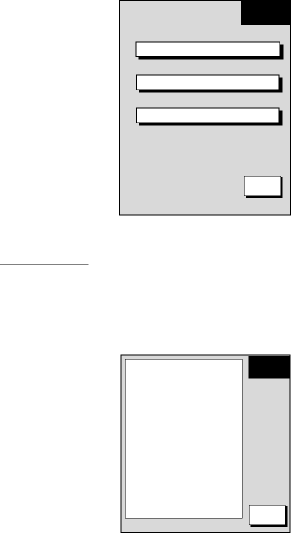
2. Use the cursor pad to select the hot page number to set and then press the
EDIT soft key. The full-screen selection window appears.
5. CUSTOMIZING YOUR UNIT
5-15
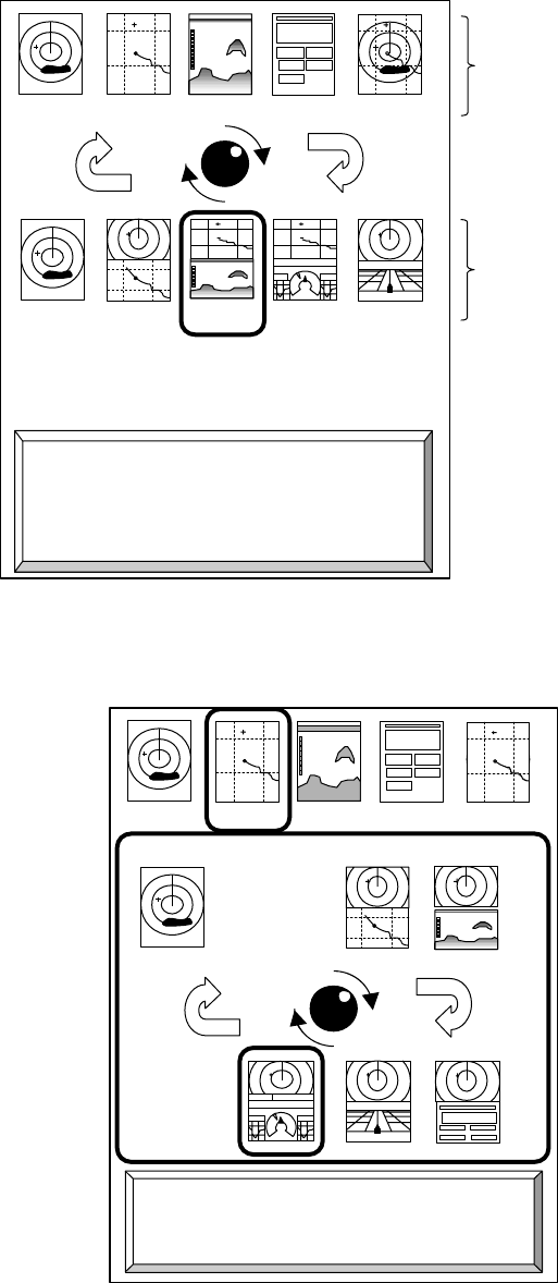
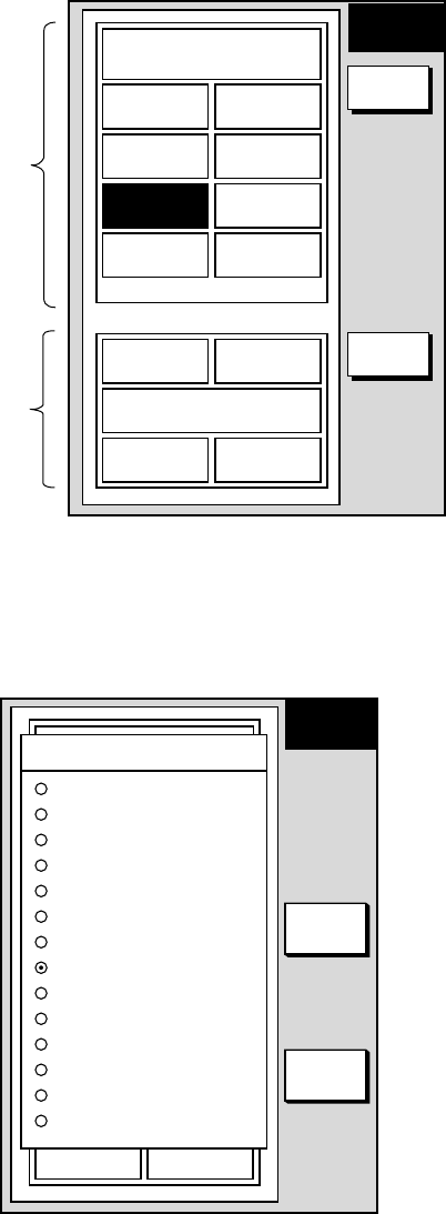
PAGE 1 PAGE 2 PAGE 3 PAGE 4 PAGE 5
RADAR PLOT SNDR NAV OVRLY
· TURN KNOB TO SELECT MODE AND PUSH
TO SET.
· PUSH ANY SOFTKEY TO SELECT IMAGE
SOURCE.
Basic display
screens
Preset combination
screen displays
Full-screen selection window
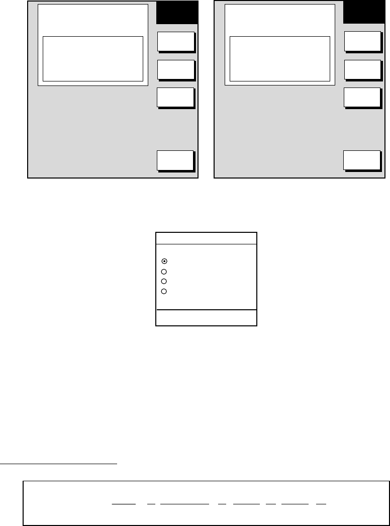
3. Rotate the [ENTER] knob to select the basic mode desired and press the
[ENTER] knob. The combination screen selection window appears.
RADAR PLOT SNDR NAV
OVRLY
PUSH ENTER KNOB.
Combination screen selection window
4. Rotate the [ENTER] knob to select the combination mode and push it to set.
5. CUSTOMIZING YOUR UNIT
5-16
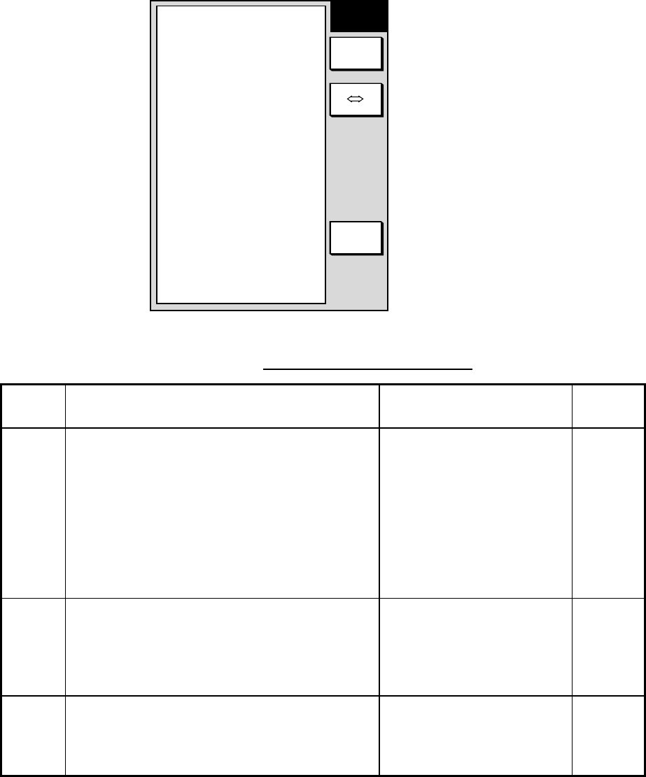
5.6 Navigator Setup
In this section you will learn how to set up the position-fixing equipment
connected to your unit.
5.6.1 Navigation data source
The nav source menu mainly selects the source of nav data and smooths position
and speed. Press the [MENU] key followed by the SYSTEM CONFIGURATION,
NAV OPTIONS and NAV SOURCE soft keys to display this menu.
NAV
OPTION
RETURN
+
-
EDIT
POSTION SOURCE
FURUNO GPS SENSOR
SPEED AVERAGE*
60s
LOCAL TIME OFFSET*
-11h00m
▲
* Non-blackbox navigator only.
Nav source menu
Contents of nav source menu
Item Description Settings Default
Setting
Position
Source Chooses source of position data. FURUNO GPS Sensor:
Blackbox GPS unit
GP: GPS navigator ( via F. NET
or NMEA connector)
LC: Loran C ( via F. NET or
NMEA connector)
All: Multiple navaid connection
( via F. NET or NMEA
connector)
All
Speed
Average Calculation of ETA is based on average ship’s speed
over a given period. If the period is too long or too
short calculation error will result. Change this setting
if calculation error occurs. The default setting is 60
seconds, which is suitable for most conditions.
0-9999 sec 60 sec
Local
Time
Offset
GPS uses UTC time. If you would rather use local
time enter the time difference between it and UTC.
Use the +⇔- soft key to switch from plus to minus
and vice versa.
-13:30 to +13:30 0
5. CUSTOMIZING YOUR UNIT
5-17
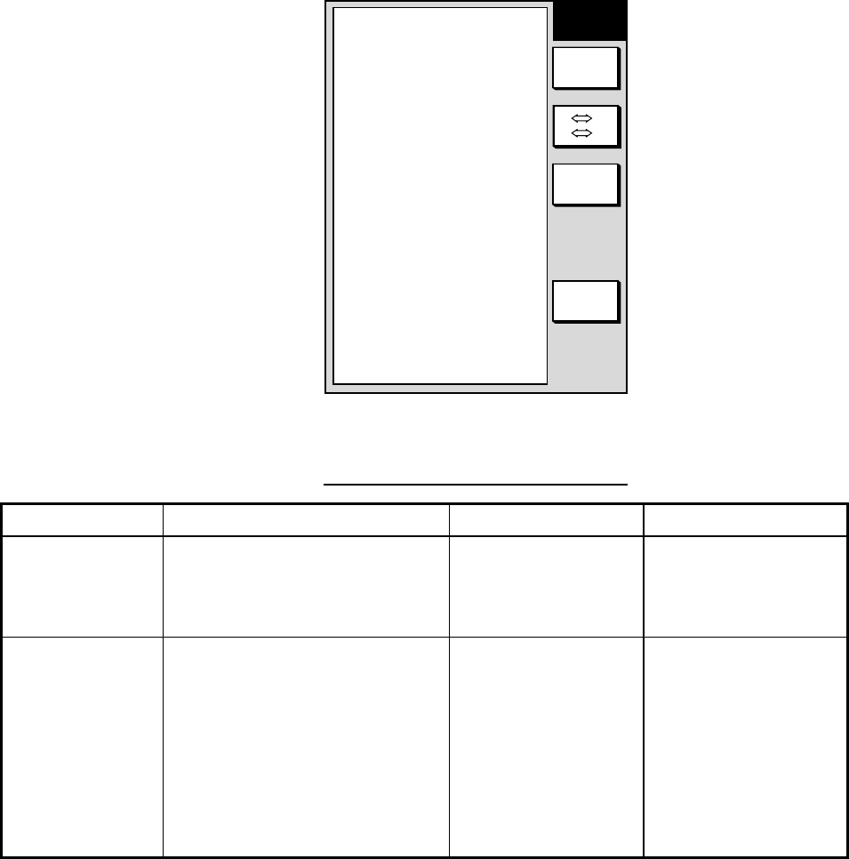
5.6.2 Blackbox GPS unit setup
The GPS unit setup menu sets up the blackbox GPS unit. Press the [MENU] key
followed by the SYSTEM CONFIGURATION, NAV OPTIONS and GPS UNIT
SETUP soft keys to display this menu.
GPS
SETUP
RETURN
GPS
MON.
EDIT
LOCAL TIME OFFSET
+00h30m
GEODETIC DATUM
WGS-84
POS SMOOTHING
00
SPD/CSE SMOOTHING
05
GPS SPD AVERAGE
60s
LAT OFFSET
0.000'
LON OFFSET
0.000'
DISABLE SAT
_ _ _
LATITUDE 34° 12.345' N
LONGITUDE
135° 12.345' E
FIX MODE 2D/3D
ANT. HEIGHT
5m
COLD START
NO
▲
N S
E W
GPS unit setup menu
Contents of GPS unit setup menu
Item Description Settings Default Setting
Local Time Offset Allows the user to use local time
(instead of UTC time). Enter time
difference between local time and
UTC time.
-13:30 to +13:30 hr 0hr
Geodetic Datum Your equipment is preprogrammed
with most of the major chart systems
of the world. Although the WGS-84
system, the GPS standard, is now
widely used other categories of
charts still exist. Select the chart
system used, not the area where your
boat is sailing. The default chart
system is WGS-84.
See Appendix for full list. WGS-84
(Continued on next page)

5. CUSTOMIZING YOUR UNIT
5-18
Contents of GPS unit setup menu (continued from previous page)
Item Description Settings Default Setting
Position Smoothing When the DOP or receiving condition
is unfavorable, the GPS fix may
change greatly, even if the vessel is
dead in water. This change can be
reduced by smoothing the raw GPS
fixes. A setting between 000 to 999 is
available. The higher setting the more
smoothed the raw data, however too
high a setting shows response time to
change in latitude and longitude. This
is especially noticeable at high ship’
speeds. 000 is the normal setting;
increase the setting if the GPS fix
changes greatly.
0-999 sec 0 sec (no position
smoothing)
Spd/Cse Smoothing During position fixing, ship’s velocity
(speed and course) is directly
measured by receiving GPS satellite
signals. The raw velocity data may
change randomly depending on
receiving conditions and other
factors. You can reduce this random
variation by increasing the
smoothing. Like with latitude and
longitude smoothing, the higher the
speed and course smoothing the
more smoothed the raw data. If the
setting is too high, however, the
response to speed and course
change slows. For no smoothing,
enter all zeroes.
0-999 sec 5 sec
GPS Speed
Average Calculation of ETA is based on
average ship’s speed over a given
period. If the period is too long or too
short calculation error will result.
Change this setting if calculation error
occurs. The default setting is 60
seconds, which is suitable for most
conditions.
0-9999 sec 60 sec
Lat Offset Offsets latitude position to further
refine position accuracy. Use the
N⇔S soft key to switch coordinate.
9.999’S – 9.999’N 0.0’ (no offset)
Lon Offset As above but for longitude. Use the
W⇔E soft key to switch coordinate. 9.999’E – 9.999’W 0.0’ (no offset)
(Continued on next page)

5. CUSTOMIZING YOUR UNIT
5-19
Contents of GPS unit setup menu (continued from previous page)
Item Description Settings Default Setting
Disable Sat Every GPS satellite is broadcasting abnormal
satellite number(s) in its Almanac, which contains
general orbital data about all GPS satellites,
including those which are malfunctioning. Using
this information, the GPS receiver automatically
eliminates any malfunctioning satellite from the
GPS satellite schedule. However, the Almanac
sometimes may not contain this information. If you
hear about a malfunctioning satellite from another
source, you can disable it manually. Enter satellite
number (max. 3 satellites) in two digits and press
the ENTER soft key.
None
Latitude Sets initial latitude position after cold start. Use the
N⇔S soft key to switch coordinate. 90°S – 90°N45°35’N
Longitude Sets initial longitude position after cold start. Use
the W⇔E soft key to switch coordinate. 180°E – 180°W 122°30’W
Fix Mode Chooses position fixing method: 2D ( three
satellites in view) , 2D/3D (three or four satellites
in view whichever is greater)
2D, 2D/3D 2D/3D
Ant.Height Enters the height of the GPS antenna unit above
sea surface. For further details refer to the
installation manual.
0-99 m 5 m
Cold Start Clears the Almanac to receive the latest Almanac. No, Yes No
GPS Monitor
(soft key) Displays GPS satellite monitor. Requires blackbox GPS sensor or GPS navigator outputting
talker GP. For further details see the chapter on Maintenance.
5. CUSTOMIZING YOUR UNIT
5-20
5.6.3 TD display setup
The TD option menu sets which Loran C or Decca chain to use. Press the
[MENU] key followed by the NAV OPTIONS and TD OPTION soft keys to display
this menu.
TD
OPTION
RETURN
NEXT
PAGE
GPS
MON.
+⇔-
EDIT
LORAN C
GRI
9970:30-55
N.PACIFIC
CORRECTION 1
+0000.0 µs
CORRECTION 2
+0000.0 µs
DECCA
CHAIN
31:R-G
HOKKAIDO
CORRECTION 1
+00.00 LANE
CORRECTION 2
+00.00 LANE
▲
TD option menu
Displaying Loran C TDs
1. Select GRI and press the EDIT soft key to show the GRI & sta. pair window.
GRI & STA. PAIR
US W COAST
9940 11-27
▲
▼
▼
Loran GRI & station pair window
2. Select GRI code. Press to enable selection of station pair, and then select
station pair. See the Loran C chain list at the end of this manual for GRI and
station pairs.
3. Press the ENTER soft key to register your selection.
4. If necessary, you may enter a position offset to refine Loran C position
accuracy. Select LORAN C CORRECTION1 or CORRECTION2 and press
the EDIT soft key. Enter correction value and press the ENTER soft key. Use
the +⇔- soft key to switch from plus to minus and vice versa.
5. Press the RETURN soft key.
6. Press the [MENU] key to close the menu.
7. Press the [MENU] key again followed by the SYSTEM CONFIGURATION and
GENERAL SETUP soft keys.
8. Select “Loran C” from “TD Display.”
9. Press the [MENU] key to close the menu.

5. CUSTOMIZING YOUR UNIT
5-21
Displaying DECCA TDs
1. Select DEC CHAIN and press the EDIT soft key to show the chain sta. pair
window.
CHAIN & STA. PAIR
SOUTH BALTIC
01 R-P
▲
▼
▼
Decca chain and station pair window
2. Select Decca chain number. Press to enable selection of lane, and then
select lane pair (R: red, G: green and P: purple). Refer to the Decca chain list
at the end of this manual.
3. Press the ENTER soft key to register your selection.
4. If necessary, you may enter position offset to refine Decca position. Select
DECCA CORRECTION1 or CORRECTION2 and press the EDIT soft key.
Enter correction value and press the ENTER soft key. Use the +⇔ - soft key
to switch from plus to minus and vice versa.
5. Press the RETURN soft key.
6. Press the [MENU] key to close the menu.
7. Press the [MENU] key again followed by the SYSTEM CONFIGURATION
and GENERAL SETUP soft keys.
8. Select “Decca” from “TD Display.”
9. Press the [MENU] key to close the menu.
5. CUSTOMIZING YOUR UNIT
5-22
5.7 Nav Data Display Setup
The nav data display provides various navigation data. You may select the data
to display and where to display it, on the monitor setup menu.
1. Press the [MENU] key to open the main menu.
2. Press the PLOTTER MENU, SYSTEM CONFIGURATION, HOT PaGE & NAV
DISPLAY, NAV DATA DISPLAY SETUP soft keys.
1
POSITION
2
SPEED 3
CSE
4
RNG 5
BRG
6
DEPTH 7
TEMP
8
LOG TRIP 9
LOG TRIP
10
SPEED 11
CSE
12
POSITION
13
RNG 14
BRG
MONITOR
SETUP
EDIT
RETURN
Positions
for full
screen
Positions
for half
screen
Nav data display setup menu
3. Use the Omnipad to select a position. Positions 1-9 are for the full-screen nav
data display and positions 10-14 for the half-screen nav data display.
4. Press the EDIT soft key. The following display appears.
1
POSITION
2
SPEED 3
CSE
4
RNG 5
BRG
6
DEPTH 7
TEMP
8
LOG TRIP 9
LOG TRIP
10
SPEED 11
CSE
12
POSITION
13
RNG 14
BRG
POSITION
WPT POSITION
SOG
STW
COURSE
BEARING
RANGE
DEPTH
TEMP
LOG TRIP
TTG
ETA
DATE
TIME
DISPLAY DATA
NAV DATA
SETUP
RETURN
ENTER
Display data window
5. CUSTOMIZING YOUR UNIT
5-23
5. Select the data to display and press the ENTER soft key.
6. Repeat steps 4-6 to set other locations.
7. Press the [MENU] key to finish.
5.8 Radar Setup
This paragraph explains how to customize the radar display to suit your
operational needs. Be sure to show the radar display before executing any of the
procedures.
5.8.1 Radar display setup
The radar display may be set up from the display setting menu, which contains
items such as EBL reference and cursor position format.
1. Press the [MENU] key to show the main menu.
2. Press the RADAR MENU soft key.
3. Press the DISPLAY SETUP soft key to show the display setup menu.
EBL REFERENCE
RELATIVE
CURSOR POSITION
RNG & BRG T
TUNING
AUTO
TX SECTOR BLANKING
OFF
NOISE REJECTION
ON
BACKGROUND COLOR
BLACK
ECHO COLOR
YELLOW
WATCHMAN
OFF
▲
DISPLAY
SETTING
EDIT
DATA
BOX
EBL REFERENCE
RELATIVE
CURSOR POSITION
RNG & BRG T
TUNING
AUTO
TX SECTOR BLANKING
OFF
NOISE REJECTION
ON
WATCHMAN
OFF
▲
DISPLAY
SETTING
EDIT
RETURN
MODEL-1700C series MODEL-1700 series
RETURN
DATA
BOX
Display setup menu

5. CUSTOMIZING YOUR UNIT
5-24
Contents of display setup menu
Item Description Settings Default Setting
EBL
Reference References EBL bearing, shown in the
EBL data box, to North (True) or heading
(Relative)
True, Relative Relative
Cursor
Position Chooses how to display cursor position. L/L: Lat/Long position of
cursor
TD: Loran or Decca TDs
RNG & BRG R: Range
and bearing in relative
bearing
RNG & BRG T: Range
and bearing in true
bearing.
RNG & BRG R
Tuning Selects receiver tuning method. For
further details see paragraph 3.6 Tuning
the Receiver.
Auto, Manual Auto
TX Sector
Blanking Turns on/off blind sector, which shows
area where no echoes are transmitted.
Blind sector area is set at installation
On, Off Off (0°)
Noise
Rejection Electrical noise, appearing on the screen
as “speckles,” may be suppressed with
the noise rejector. Note that there are
some forms of interference which cannot
be suppressed
On, Off Off
Background
(MODEL-
1700C series)
Chooses colors of background, range
rings and characters. Color 1
Background: Black
Rings: Green
Characters: Green
Color 2
Background: Blue
Rings: White
Characters: White
Color 3
Background: Dark Blue
Rings: White
Characters: White
Color 4
Background: Black
Rings: Green
Characters: Red
Color 1
Echo Color
(MODEL-
1700C series)
Chooses echo color. Yellow, Green,
Multi (Echoes shown in
red, yellow or green in
order of descending
strength.)
Yellow
Watchman Sets watchman stand-by interval. For
further details see paragraph 3.23
Watchman.
5, 10, 20 min, Off Off
5. CUSTOMIZING YOUR UNIT
5-25
5.8.2 Radar range setup
The radar has 16 (km) and 17 (nm) ranges, some of which you may not require.
You may turn off ranges you do not require, from the range setup menu. After
choosing the ranges desired change the range to activate range settings.
Note that at least two ranges (excluding maximum range) must be turned on.
When less than two ranges are turned on a buzzer sounds.
1. Press the [MENU] key to show the main menu.
2. Press the RANGE SETUP soft key to show the range setup menu.
RANGE
SETUP
RETURN
ON/OFF
0.125nm
0.25nm
0.5nm
0.75nm
1nm
1.5nm
2nm
3nm
4nm
6nm
8nm
12nm
16nm
24nm
36nm
48nm
64nm
MAX RANGE 64nm
ON
ON
ON
ON
ON
ON
ON
ON
ON
ON
ON
ON
ON
ON
ON
ON
ON
▲
Range unit: nm
RANGE
SETUP
RETURN
ON/OFF
0.25km
0.5km
0.75km
1km
1.5km
2km
3km
4km
6km
8km
12km
16km
24km
36km
48km
64km
MAX RANGE 64km
ON
ON
ON
ON
ON
ON
ON
ON
ON
ON
ON
ON
ON
ON
ON
ON
▲
Range unit: km
Range setup menu
3. Use the Omnipad to select the range which you want to turn on or off.
4. Press the ON/OFF soft key to turn the range on or off as appropriate.
5. Press the RETURN soft key.
6. Press the [MENU] key to close the menu.
5. CUSTOMIZING YOUR UNIT
5-26
5.8.3 Function key setup
The function keys, shown when the soft keys are turned off, provide one-touch
call up of a desired function. The default radar function key settings are
#1 function key: Gain
#2 function key: A/C SEA
#3 function key: Data box
#4 function key: Range rings
#5 function key: Change control
If the above settings are not to your liking you may change them as follows:
1. Show the radar display.
2. Press the [MENU] key.
3. Press the FUNCTION KEY SETUP soft key.
FUNC
KEY
RETURN
EDIT
SOFT KEY1
GAIN G
A
I
SOFT KEY2
A/C SEA S
E
A
SOFT KEY3
DATA BOX ON/OFF D
B
X
SOFT KEY4
RINGS R
N
G
SOFT KEY5
CHANGE CONTROL C
N
T
▲
Function key menu (radar)
4. Select the function key you want to program and press the EDIT soft key. Use
the cursor pad to scroll the screen if necessary.
▲
FUNCTION
OFF
HEADING LINE OFF
MODE
GAIN SENSITIVITY
A/C SEA
A/C RAIN
FTC
ECHO STRETCH
PULS LENGTH
ZOOM
OFFCENTER
TRAIL
RINGS
Function menu (radar)

5. CUSTOMIZING YOUR UNIT
5-27
5. Select function desired and press the RETURN soft key. See the table on the
next page for details.
6. Press the [MENU] key to close the menu.
Radar functions keys
Function Action Function Key
Label
NO FUNCTION Assigns no function.
HEADING LINE Turns heading line on/off. HL
MODE Selects presentation mode. MOD
GAIN SENSITIVTY Shows manual or automatic gain window depending on
current gain mode. GAI
A/C SEA Shows manual or automatic A/C SEA window depending
on current A/C SEA mode. SEA
A/C RAIN Shows manual or automatic A/C RAIN window depending
on current A/C RAIN mode. RAI
FTC Displays FTC window. Adjust FTC with the [ENTER]
knob. FTC
ECHO STRETCH Turns echo stretch on/off. ES
PULSE LENGTH Sets pulselength (long or short). PLS
ZOOM Touch-and-release to double size of cursor-selected
target, in zoom window. Press again to fix cursor. Press
and hold down to turn zoom off.
ZOM
OFFCENTER Press to shift display center to cursor location. Press
again to turn shift off and return cursor to display center. SFT
TRAIL Starts/stops target trails. TRL
RINGS Turns range rings on/off. RNG
TLL Outputs cursor position, in NMEA format, to navigator. TLL
ALM Displays alarm soft keys. ALM
EBL Displays EBL if it is off; enables control of EBL if its active. EBL
VRM Displays VRM if it is off; enables control of VRM if its
active. VRM
TTM Turns TTM data on/off. Place cursor on TTM target to
finds its data. Press and hold down to turn off TTM target
and its data.
TTM
(Continued on next page)

5. CUSTOMIZING YOUR UNIT
5-28
Radar function keys (continued from previous page)
Function Action Function Key Label
WPT MARK Turns waypoint marker on/off. WMK
WATCHMAN Turns watchman on/off WTM
ACQ (For
ARPA-equipped
network radar)
Acquires and tracks cursor-selected target. ARP
CHANGE
CONTROL Changes control in combination display. CHG
RADAR
SOURCE Selects source or radar picture. R-S
DATA BOX
ON/OFF Turns data boxes on/off. DBX
5. CUSTOMIZING YOUR UNIT
5-29
5.9 Sounder Setup
This section shows you how to customize your sounder to your liking. You can set
fish alarm sensitivity, fine tune sensors, etc.
5.9.1 System setup
1. Show the sounder display and press the [MENU] key.
2. Press the SYSTEM SETUP soft key.
SOUNDER
SETUP
RETURN
SENSOR
SETUP
EDIT
FISH ALARM LEVEL
0
TX
ON
TVG 200kHz
5
TVG 50kHz
5
ECHO OFFSET 200kHz
0
ECHO OFFSET 50kHz
0
SEABED LEVEL 200kHz
80
SEABED LEVEL 50kHz
80
KP PULSE
INTERNAL
SMOOTHING
NORMAL
▲
Sounder setup menu
System setup menu description
Item Description Settings Default Setting
Fish Alm Lvl Sets the fish alarm sensitivity; which
echo strength will trigger the alarm. High: only the
strongest echoes
trigger the alarm.
Normal: Echoes
from strong to
medium strength
trigger the alarm.
Low: Any echo
triggers the
alarm.
Normal
TX Turns TX power on/off. The default
setting is ON. On, Off On

5. CUSTOMIZING YOUR UNIT
5-30
Item Description Settings Default Setting
TVG
(50 kHz,
200kHz)
TVG (Time Varied Gain)
compensates for propagation
attenuation of the ultrasonic waves.
It does this by equalizing echo
presentation so that fish schools of
the same size appear in the same
density in both shallow and deep
waters. In addition, it reduces
surface noise. Note that if the TVG
level is set too high short range
echoes may not be displayed.
0-9 5 (both 50 kHz and 200
kHz)
Echo Offset
(50 kHz,
200kHz)
If the on-screen echo level appears
to be too weak or too strong and the
level cannot be adjusted
satisfactorily with the gain control,
adjust echo offset to compensate for
too weak or strong echoes. The
default setting for both 200 kHz and
50 kHz is zero.
-50 - +50 0 (both 50 kHz and 200
kHz)
Seabed
Level
(50 kHz, 200
kHz)
If the depth indication is unstable in
automatic operation or the bottom
echo cannot be displayed in reddish-
brown by adjusting the gain control
in manual operation, you may adjust
the bottom echo level detection
circuit, for both 50 kHz and 200 kHz,
to stabilize the indication. Note that if
the level is set too low weak echoes
may be missed and if set too high
the depth indication will not be
displayed.
20- 200 80 (both 50 kHz and 200
kHz)
KP Pulse Selects source of keying pulse. Internal,
External Internal
Smoothing Smooths echoes to present stable
display. The higher the setting the
greater the smoothing.
SM1-SM8,
OFF SM3
Sensor
Setup
(soft key)
Offsets speed, depth and water
temperature indications. See next section for details.
5. CUSTOMIZING YOUR UNIT
5-31
5.9.2 Sensor setup
The sensor setup menu lets you compensate for speed, temperature and depth
error in the sensor(s) connected to the blackbox sounder.
1. Show the sounder display and press the SENSOR SETUP soft key at the
system setup menu to show the sensor setup menu. The current readout for
speed, water temperature, depth and sonic speed are shown at the bottom of
the menu.
ES SENS
SETUP
RETURN
EDIT
SPEED ADJUST
+ 0%
TEMP. ADJUST
+ 0°F
DEPTH ADJUST
+12ft
SONIC SPEED ADJUST
+ 200m/s
▲
SPEED
12.3kt
DEPTH
125ft
TEMPERATURE
78°F
SONIC SPEED
1700m/s
Sensor setup menu
2. Select item to adjust and press the EDIT soft key.
3. Display appropriate value as below.
Speed and temperature: Enter appropriate percentage. For example, if the
water temperature readout is 77°F but the actual water temperature is 75.4°F,
enter –2(%).
Depth: Enter plus or minus value. For example, if the depth readout is 125 ft
but the actual depth is 126 ft, enter +1(ft).
Sonic speed adjustment: Sets the speed of sound used by the blackbox
sensor. Normally no adjustment is required, however if echoes are returning
too slow or too fast adjust the value as appropriate.
Sensor setup menu settings
Item Settings Default Setting
Speed Adjust -50 -+50% 0% (no offset)
Temp Adjust -20 -+20°C, -40 - +40°F 0% (no offset)
Depth Adjust -10 - +40 m; -30 – 130 ft;
-6 - +25 fa, -6 – 25 pb
0 ft, m, fa, pb
(no offset)
Sonic Speed
Adjust
-500 - +500 m/s 0 m/s (no offset)
4. Press the RETURN soft key followed by the [MENU] key.
5. CUSTOMIZING YOUR UNIT
5-32
5.9.3 Sounding range, zoom range, bottom lock range
This paragraph shows you how to set custom ranges and choose zoom and
bottom lock ranges.
1. Show the sounder display and press the [MENU] key to open the main menu.
2. Press the SOUNDER RANGE SETUP soft key to show the sounder range
menu.
SOUNDER
SETUP
RETURN
EDIT
RANGE 1
5 m
RANGE 2
10 m
RANGE 3
20 m
RANGE 4
40 m
RANGE 5
80 m
RANGE 6
150 m
RANGE 7
300 m
RANGE 8
1200 m
ZOOM RANGE
20 m
B/L RANGE
3 m
▲
Sounder range menu
3. Select the range to change and press the EDIT soft key. For the zoom range
the available settings are as below.
4. Use the cursor pad to set range desired.
5. Press the RETURN soft key.
6. Press the [MENU] key to finish.
Default ranges
Range 1 Range 2 Range 3 Range 4 Range 5 Range 6 Range 7 Range 8
5 m 10 m 20 m 40 m 80 m 150 m 300 m 1200 m
15 ft 30 ft 60 ft 120 ft 200 ft 400 ft 1000 ft 4000 ft
3 fa 5 fa 10 fa 20 fa 40 fa 80 fa 150 fa 650 fa
3 pb 6 pb 12 pb 24 pb 50 pb 100 pb 200 pb 700 pb
Setting range: 2 m –1200m, 7 ft – 4000 ft, 1 fa – 650 fa, 1 pb – 700 pb
Zoom range, Bottom lock range
Item Settings Default Setting
Zoom Range 2 m – 1200 m, 7 ft – 4000 ft,
1 fa – 650 fa, 1 pb – 700 pb
10 m, 30 ft, 10 fa, 10 pb
B/L Range 3 m, 10 ft, 2 fa, 2 pb
6 m, 20 ft, 3 fa, 3 pb
6 m, 20 ft, 3 fa, 3pb
5. CUSTOMIZING YOUR UNIT
5-33
5.9.4 Function key setup
The function keys, shown when the soft keys are turned off, provide one-touch
call up of a desired function. The default sounder function key settings are
#1 function key : Auto mode
#2 function key: Gain 200 kHz
#3 function key: Clutter
#4 function key: Picture advance
#5 function key: Hue
If the above settings are not to your liking you may change them as follows:
1. Show the sounder display.
2. Press the [MENU] key.
3. Press the FUNCTION KEY SETUP soft key.
FUNC
KEY
RETURN
EDIT
SOFT KEY1
AUTO MODE M
O
D
SOFT KEY2
GAIN 200 G
2
0
SOFT KEY3
CLUTTER C
L
T
SOFT KEY4
PIC. ACV P
A
SOFT KEY5
HUE H
U
E
▲
Function key menu (radar)
4. Select the function key you want to program and press the EDIT soft key. A
menu shows the functions available.
▲
FUNCTION
OFF
AUTO MODE
GAIN 200
GAIN 50
SHIFT
N. LEVEL
CLUTTER
W.MAKER
HUE
SUG.LEVEL
CHANGE CONTROL
PIC.ADV
TEMP.GRP
Function menu (sounder)

5. CUSTOMIZING YOUR UNIT
5-34
5. Select function desired and press the RETURN soft key. See the table on the
next page for details.
6. Press the [MENU] key to close the menu.
Sounder functions keys
Function Action Function Key Label
MODE Automatic sounder mode. MOD
GAIN 200 kHz Adjusts gain for 200 kHz. G20
GAIN 50 kHz Adjusts gain for 50 kHz. G 5
SHIFT Shifts range in manual operation. SFT
NOISE LEVEL Suppresses noise. NLV
CLUTTER Suppresses clutter. CLT
WHITE MARKER Sets white marker. WMK
HUE (GD-1700C) Sets hue. HUE
SIGNAL LEVEL
(GD-1700C) Erases weak signals. SLV
PICTURE ADVANCE Sets picture advance speed. P A
TEMP GRAPH
ON/OFF Turns temperature graph on/off. T G
TVG 200 Sets TVG for 200 kHz. TV2
TVG 50 Sets TVG for 50 kHz. TV5
ECHO OFFSET 200 Offsets echo strength for 200 kHz. EO2
ECHO OFFSET 50 Offsets echo strength for 500 kHz. EO5
SMOOTHING Sets smoothing rate. SMZ
ZOOM RANGE Sets zoom range for marker zoom display. ZMR
B/L RANGE Sets bottom lock range for bottom lock display. BLR
CHANGE CONTROL Changes control in combination display. CHG
TLL Outputs current position in NMEA format. Also
inscribes line on sounder and registers position
as a waypoint.
TLL
DATA BOX ON/OFF Turns data boxes on/off. DBX
NO FUNCTION Assigns no function.
5. CUSTOMIZING YOUR UNIT
5-35
5.10 Data Port Setup
The display unit has four ports on its rear panel for connection of external
equipment: GPS/NMEA port, GPS port, PC/NMEA/EXT BUZZ port and NavNet
port. Set up these ports according to the equipment connected to them. The
GPS/NMEA, GPS, and PC/NMEA/EXT BUZZ ports are set up on the port setup
menu. For the NavNet port see the installation menu.
5.10.1 GPS/NMEA port (MODEL-1700 series only)
The navigator connected to the GPS/NMEA port can be set up on the
GPS/NMEA port menu.
1. Press the [MENU] key to open the main menu.
2. Press the SYSTEM CONFIGURATION, SYSTEM SETUP, PORT SETUP and
GPS/NMEA soft keys to show the GPS/NMEA menu.
GENERAL
SETUP 1
RETURN
NEXT
PAGE
EDIT
KEY BEEP
ON
LANGUAGE
ENGLISH
RANGE/SPEED UNIT
nm, kt
TEMP UNIT
°C
DEPTH UNIT
ft
TEMP SOURCE
NMEA
DEPTH SOURCE
NMEA
RESET TRIP LOG
NO
▲
Page 1
(MODEL-1700C series, MODEL-1700 series)
PREV.
PAGE
GENERAL
SETUP 2
EDIT
LAT/LON DISPLAY
DD° MM.MMM'
TD DISPLAY
LC
SPEED DISPLAY
SOG
POSITION DISPLAY
LAT&LON
TIME DISPLAY
24hours
I/R REMOTE MODE
A
RANGE, BEARING MODE
RHUMB LINE
BEARING
MAGNETIC
MAG VARIATION
AUTO 7.0° W
▲
Page 2 (MODEL-1700C series)
PREV.
PAGE
GENERAL
SETUP 2
EDIT
LAT/LON DISPLAY
DD° MM.MMM'
TD DISPLAY
LC
SPEED DISPLAY
SOG
POSITION DISPLAY
LAT&LON
TIME DISPLAY
24hours
I/R REMOTE MODE
A
RANGE, BEARING MODE
RHUMB LINE
BEARING
MAGNETIC
MAG VARIATION
AUTO 7.0° W
DISPLAY MODE
NORMAL
▲
Page 2 (MODEL-1700 series)
GPS/NMEA port menu
5. CUSTOMIZING YOUR UNIT
5-36
Contents of GPS/NMEA port setup menu
Item Description Settings Default Setting
GPS Sensor
Connected Selects whether blackbox GPS unit is connected
to the GPS/NMEA port. Yes, No No
Output Format Selects NMEA output version of FURUNO GPS
sensor. NMEA Ver. 1.5,
NMEA Ver. 2.0 NMEA Ver. 2.0
Lat/Lon Format Selects latitude/longitude format to output. DD °MM.MM’,
DD °MM.MMM,
DD°MM.MMMM’
DD°MM.MMMM’
Output Destination Selects whether to output route (sentence RTE)
and waypoint data (sentence WPL) when
destination is set.
Yes, No No
Select Sentence
(soft key) Selects data sentence(s) to output. Select sentence with the Omnipad and press the ON/OFF soft
key to show On or “- -“ (Off) as appropriate. The data sentence menu below shows the default
settings.
Note 1: The depth sentences DBT and DBS may be selected together on Ver. 1.5; only DPT is
available for Ver. 2.0.
Note 2: BWC (great circle) and BWR (rhumb line) may be selected together.
SELECT
SNTNC
RETURN
ON/OFF
AAM
APB
BOD
BWR
DPT
GGA
GLL
GTD
MTW
RMA
RMB
RMC
VHW
VTG
WPL
XTE
ZDA
--
--
--
--
ON
--
ON
--
--
--
ON
ON
--
ON
--
--
ON
▲
Version 2.0 (rhumb line)
SELECT
SNTNC
RETURN
ON/OFF
AAM
APB
BOD
BWR
DBT&DBS
GGA
GLL
GTD
MTW
RMA
RMB
RMC
TTM
VHW
VTG
WPL
XTE
ZDA
--
--
--
--
ON
--
ON
--
--
--
ON
ON
--
--
ON
--
--
ON
▲
Version 1.5, W/ARPA (great circle)
Data sentences
5. CUSTOMIZING YOUR UNIT
5-37
5.10.2 NMEA PORT menu
The NMEA port setup menu sets up the equipment connected to the NMEA port.
The contents of the menu are similar to that of the GPS/NMEA PORT menu. You
can display this menu by pressing the [MENU] key followed by the SYSTEM
CONFIGURATION, SYSTEM SETUP, PORT SETUP AND GPS/NMEA soft keys.
5.10.3 PC/NMEA/EXT BUZZ. PORT menu
The PC/NMEA ext buzz port menu sets up of the equipment connected to the
PC/NMEA EXT BUZZ port.
1. Press the [MENU] key to open the main menu.
2. Press the CONFIGURATION, SYSTEM SETUP, PORT SETUP AND
GPS/NMEA soft keys to show the PC/NMEA/EXT BUZZ menu.
NMEA
PORT
RETURN
SELECT
SNTNC
EDIT
NMEA OUTPUT FORMAT
NMEA 0183 VER2.0
BAUD RATE
4800bps
BIT LENGTH
8bit
STOP BIT
1bit
PARITY
NONE
(CONTROL: Xon/Xoff)
▲
WIRE INFO.
TxD-H >1>---WHITE
RxD-C >2>---BLACK
RD-H >3>---YELLOW
RD-H >4>---GREEN
+12V >5>---RED
EXT BUZZ >6>---BLUE
GND >7>---SHIELD
PC/NMEA/EXT BUZZ PORT menu
Contents of PC/NMEA/EXT BUZZ PORT menu
Item Description Settings Default Setting
NMEA
Output
Format
SelectsNMEA output format NMEA Ver. 1.5,
NMEA Ver. 2.0 NMEA Ver. 2.0
Baud Rate Sets baud rate of equipment
connected to this port. 4800, 9600, 19200,
38400, 57600(bps) 4800(bps)
Bit Length Sets character length. 8 bit, 7 bit 8 bit
Stop Bit Sets number of stop bits. 1 bit, 2 bit 1 bit
Parity Sets parity bit. Even, Odd, None None
Select
Sntnc (soft
key)
Sets Ver 2.0 sentences to output. For further details see the illustration and
and table on page 5-36.
6. DATA TRANSFER
6-1
6. DATA TRANSFER
This chapter provides information for saving and replaying memory cards, and
uploading and downloading data.
6.1 Memory Card Operations
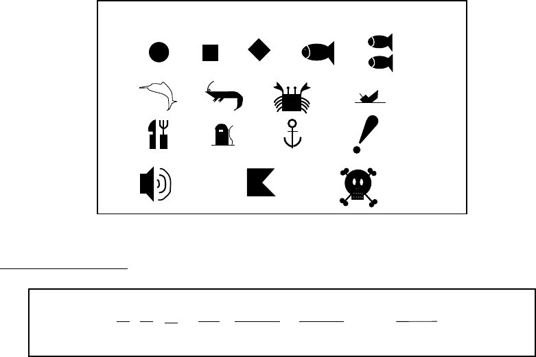
The memory cards function to store data, and the following data can be saved:
• Marks/lines
• Waypoints/routes
• Track
• Configuration (menu settings)
6.1.1 Formatting memory cards
Before you can use a memory card it must be formatted. This prepares the card
for use with the system. Note that formatting a used card erases all saved data.
1. Insert the memory card you want to format into the card slot.
2. Press the [MENU] key followed by the SYSTEM CONFIGURATION, DATA
TRANSFER, UPLOAD/DOWNLOAD DATA and SAVE DATA TO MEMORY
CARD soft keys to show the save data menu.
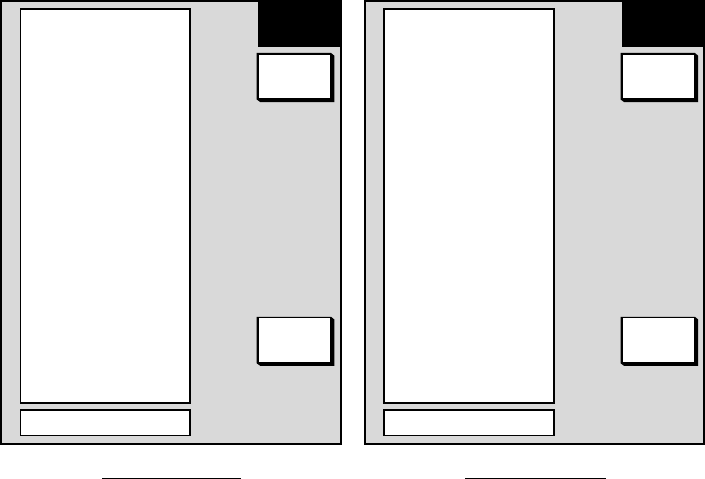
TRACKOFF
WAYPOINT & ROUTES
OFF
MARK/LINE
OFF
SETTING DATA
OFF
▲
SAVE
DATA
EDIT
SAVE
FORMAT
RETURN
Save data menu
3. Press the FORMAT soft key. You are asked if you are ready to format the
memory card.
4. Push the [ENTER] knob to format (or press the [CLEAR] key to escape).
“NOW FORMATTING MEMORY CARD” appears. Do not remove the card
while it is being formatting. When the formatting is completed, “FORMAT
COMPLETED” appears.
5. Push the [ENTER] knob to finish.
6. DATA TRANSFER
6-2
6.1.2 Saving data to a memory card
1. Insert a formatted memory card into the slot.
2. Press the [MENU] key followed by the CONFIGURATION, DATA TRANSFER,
UPLOAD/DOWNLOAD DATA and SAVE DATA TO MEMORY CARD soft
keys to show the SAVE DATA display.
TRACKOFF
WAYPOINT & ROUTES
OFF
MARK/LINE
OFF
SETTING DATA
OFF
▲
LOAD
DATA
EDIT
LOAD
RETURN
Load data menu
3. Select item to save.
4. Press the EDIT soft key.
5. Select ON.
6. Press the ENTER soft key.
7. Repeat from steps 4 to 7 to save other data if desired.
8. Press the SAVE DATA soft key. The message “NOW SAVING DATA TO
MEMORY CARD. DO NOT TURN OFF THE POWER UNTIL SAVING IS
COMPLETED.” appears.
When saving is completed, COMPLETE SAVING DATA appears. Press the
[ENTER] knob.

6. DATA TRANSFER
6-3
Error messages
Various error messages appear to alert you to memory card-related error. These
are tabulated below.
Error messages
Error Message Reason Remedy
Memory card not
inserted. Insert card.
Press “ENTER” key to
continue.
Memory card not
inserted.
Push the [ENTER] knob to return to the
SAVE DATA display.
Memory card not
formatted. Press
“ENTER” key to
continue.
Unformatted memory
card.
Push the [ENTER] knob to return to the
SAVE DATA display. Format the card
referring to the previous page.
Wrong card inserted.
Insert memory card.
Press “ENTER” key to
continue.
Chart card inserted
instead of memory
card.
Insert memory card.
Overwrite following
data OK?
(Track)
Data type to be
recorded exists on
memory card. (Two
or more of same type
of data cannot be
recorded.)
Push the rotary encoder key to overwrite
same data type on the card, or press the
[CLEAR] key to escape.
6. DATA TRANSFER
6-4
6.1.3 Playing back from a memory card
Data (track, marks, waypoints, configuration) can be loaded from a memory card
and displayed on the screen. This feature is useful for observing past data and
setting up the equipment for a specific purpose (with “configuration”).
1. Press the [MENU] key followed by the SYSTEM CONFIGURATION and
DATA TRANSFER soft keys.
2. Press the UPLOAD/DOWNLOAD DATA soft key.
3. Press the LOAD DATA FROM MEMORY CARD soft key to show the LOAD
DATA menu.
TRACKOFF
WAYPOINT & ROUTES
OFF
MARK/LINE
OFF
SETTING DATA
OFF
▲
LOAD
DATA
EDIT
LOAD
RETURN
Load data menu
4. Select item to load.
5. Press the EDIT soft key.
6. Select ON. Press the ENTER soft key or the [ENTER] knob. If the memory
card does not contain the item selected, the buzzer sounds and ON cannot be
selected.
7. After you select all items desired, press the LOAD DATA soft key to load data.
The message “NOW LOADING DATA FROM MEMORY CARD. DO NOT
TURN OFF THE POWER UNTIL SAVING IS COMPLETED.” appears.
8. After loading is completed, push the [ENTER] knob to finish.
Notes on loading data
Track: Since loaded track data is added to internal track, oldest track will be
entered when the track memory capacity is exceeded.
Waypoint/route: The loaded data substitutes for previously stored.
Mark/line: The loaded data is added to internal data. When the mark/line
memory becomes full no marks may be entered.
Configuration: The loaded data replaces current configuration settings. Push
the [ENTER] knob to restart. If the memory card is ejected while loading or data
could not be loaded, Push the [ENTER] knob to restart with default settings. Note
that track memory capacity is not saved or loaded.
6. DATA TRANSFER
6-5
6.2 Uploading, Downloading Data
You can upload waypoint and route data to a PC and download the same data
from a PC, through the PC/NMEA/EXT BUZZ connector at the rear of the display
unit.
6.2.1 Setting communication software on the PC
Set communication software on the PC as follows:
Baud Rate: 4800 bps
Character Length: 8 bit
Stop bit: 1 bit
Parity: None
X Control: XON/XOFF
The following data can be downloaded/uploaded between a personal computer
and this equipment:
• Waypoint data (In alphanumeric order)
• Route data (In order of route number)
• End of sentence
Note 1: There are two kinds of data for route data: route data and route comment
data.
Note 2: DGPS position fix is not available when uploading or downloading data.
Note 3: Wiring information is provided on the PC/NMEA/EXT BUZZ PORT menu.
6.2.2 Uploading (downloading) data
1. Connect the PC to the equipment as shown below.
2. Press the [MENU] key to show the main menu.
3. Press the SYSTEM CONFIGURATION soft key.
4. Press the DATA TRANSFER soft key.
5. Press the UPLOAD/DOWNLOAD DATA soft key.
6. Press the DOWNLOAD WPT/RTE DATA TO PC or UPLOAD WPT/RTE
DATA FROM PC as appropriate.
6. DATA TRANSFER
6-6
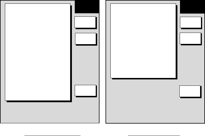
WAYPOINT & ROUTES
OFF
MARK/LINE
OFF
▲
UPLOAD
EDIT
UPLOAD
SELECT
BPS
RETURN
WIRE INFORMATION
DISPLAY UNIT PC* DSUB9
NMEA IN >1>-WHITE
NMEA IN >2>-BLACK
TxD >3>-YELLOW-<2<RD
RxD >4>-GREEN -<3<SD
+12V >5>-RED
EXT BUZZ>6>-BLUE
GND >7>-SHIELD-<5<SG
RS232C SETTINGS ARE
· 4800BPS,
· 8BIT,
·1STOP BIT,
· PARITY NONE.
· CONTROL Xon/Xoff
WAYPOINT & ROUTES
OFF
MARK/LINE
OFF
▲
DOWN-
LOAD
EDIT
DOWN-
LOAD
SELECT
BPS
RETURN
WIRE INFORMATION
DISPLAY UNIT PC* DSUB9
NMEA IN >1>-WHITE
NMEA IN >2>-BLACK
TxD >3>-YELLOW-<2<RD
RxD >4>-GREEN -<3<SD
+12V >5>-RED
EXT BUZZ>6>-BLUE
GND >7>-SHIELD-<5<SG
RS232C SETTINGS ARE
· 4800BPS,
· 8BIT,
·1STOP BIT,
· PARITY NONE.
· CONTROL Xon/Xoff
Upload and download menus
7. To change the baud rate, press the SELECT BPS soft key.
BAUD RATE
▲
▼
4800bps
9600bps
19200bps
38400bps
57600bps
DEFAULT: 4800bps
Baud rate window
8. Select baud rate and press the RETURN soft key.
9. Press the DOWNLOAD WPT/RTE or UPLOAD WPT/RTE soft key as
appropriate. You are asked if you are ready to download (upload) waypoints
and routes.
10. Press the [ENTER] knob to download (upload).
Waypoint data format
1 2 3 4 5 6 77
PFEC, GPwpl, llll.llll, a, yyyyy.yyy, a, c----c, c, c----c, a <CR><LF>
8
Waypoint data format
1: Waypoint latitude
2: N/S
3: Waypoint longitude
4: E/W
5: Waypoint name (Number of characters is fixed to 6 and space code is placed
when the number of characters are less than 6.)
6: Waypoint color
6. DATA TRANSFER
6-7
7: Waypoint comment (1 byte for mark code + 13 characters of comment.)
1st byte of mark code: Fixed to “@”.
2nd byte of mark code: Internal mark code. See Note 1.
8. Information of marking waypoint. Always set to “A”.
“A”: Displayed
“V”: Not displayed
Note: Following characters can be used for comments:
_ABCDEFGHIJKLMNOPQRSTUVWXYZ0123456789&'#
=9 =: =; =< = =
=> =? =@ =A
=B =C =D =E
=F =G =H
Characters available for comment
Route data menu
$GPRTE, x, x, a, ccc, c----c, c----c, ... , c----c <CR><LF>
1 2 345612
Route data format
1: Number of sentences required for one complete route data (1 to 4). See Note
2.
2: Number of sentences currently used (1 to 4)
3: Message mode (Always set to C)
4: Route No. (001 to 300, 3 digits required)
5 through 12: Waypoint name (Max. 8 names, length of each waypoint name is
fixed to 7 byte)
Note: A route can may contain 35 waypoints, and the GPRTE sentence for one
route data may exceed 80 byte limitation. In this case, route data is divided
into several GPRTE sentences (Max. 4 sentences). This value shows the
number of sentences the route data has been divided.
6. DATA TRANSFER
6-8
Route comment data format
12
$PFEC, GPrtc, xx, c----c <CR><LF>
Route comment format
1: Route No. (01 to 200, 3 digits required)
2: Route comment (Max. 16 characters, variable length)
The same characters of the comment for waypoint comment can be used.
End of sentence
$PFEC, GPxfr, CTL, E <CR><LF>
End of sentence
6.3 Loading Waypoint Data from Yeoman
Connect the Yeoman equipment to the GPS/NMEA connector on this
equipment and then follow the procedure below:
1. Press the [MENU] key.
2. Press the SYSTEM CONFIGURATION key.
3. Press the DATA TRANSFER soft key.
4. Press the RECEIVE DATA BY NavNet soft key.
5. You are asked if you are sure to receive waypoint data from yeoman
equipment. Press the [ENTER] knob to receive the data.
The message “NOW RECEIVING YEOMAN DATA. PUSH SOFTWARE KEY
‘STOP’ TO STOP RECEIVING.” Is displayed. If waypoint capacity is reached
the message “WAYPOINTS ARE FULL. CAN NOT RECEIVE ANY DATA.
PUSH ANY KEY TO STOP.” appears.
6. To stop receiving, press the STOP soft key.
7. After waypoints have been received, press the RETURN soft key followed by
the [MENU] key.
6. DATA TRANSFER
6-9
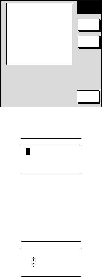
6.4 Receving Data Via the NavNet
You can receive track, waypoint, routes, marks and lines via NavNet equipment
outputting such data as below.
1. Press the [MENU] key.
2. Press the SYSTEM CONFIGURATION soft key.
3. Press the RECEIVE DATA BY NavNet soft key.
HOST NAME
PLOT1
TRACK
ON
WAYPOINTS & ROUTES
OFF
MARK/LINE
OFF
▲
RECEIVE
DATA
EDIT
RCV
RETURN
Receive data (NavNet) menu
4. Select HOST NAME and press the EDIT soft key.
HOST NAME
PLOT1
Host name window
5. Use the [ENTER] knob to input host name and press the RETURN soft key.
Use the CLEAR soft key to clear data selected with the cursor.
6. Select TRACK and press the EDIT soft key.
TRACK
▲
▼
ON
OFF
Track window
7. Select ON or OFF as appropriate and press the RETURN soft key.
8. Turn WAYPOINTS & ROUTES and MARK & LINE on or off as appropriate.
6. DATA TRANSFER
6-10
9. Press the RCV soft key to receive data.
The message “NOW RECEIVING DATA.” is displayed. IF no data could be
found the message “(HOST NAME)’ IS NOT FOUND.” appears.
10. When the transfer is completed, the message “DATA TRANSFER
COMPLETED.” appears. Push the [ENTER] knob to finish.
11. Press the [MENU] key to close the menu.
7-1
7. MAINTENANCE,
TROUBLESHOOTING
This chapter provides information necessary for keeping your unit in good
working order and remedying simple problems.
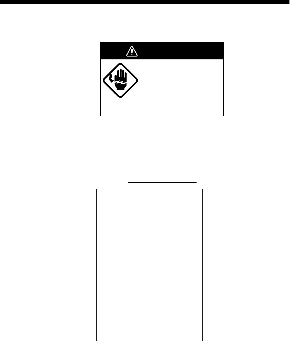
WARNING
Do not open the equipment.
Hazardous voltage which can
cause electrical shock exists
inside the equipment. Only
qualified personnel should
work inside the equipment.
7.1 Periodic Maintenance
Regular maintenance is important for continued performance. A maintenance
schedule should be established and should at least include the items tabulated
below.
Maintenance program
Item Check point Remedy
Display unit
connectors Check for tight connection. Tighten loosened connectors
LCD The LCD will, in time, accumulate a
coating of dust which tends to dim the
picture. Wipe LCD lightly with soft cloth
to remove dust.
Do not use chemical cleaners to
clean any part of the display unit;
they can remove paint and
markings.
Ground terminal Check for tight connection and
corrosion. Clean or replace as necessary.
Antenna unit Check for loosened and corroded bolts. Tighten loosened bolts. Replace
heavily corroded bolts.
Antenna cable • Check connection point for
watertightness.
• Check connector for tightness and
corrosion.
• Check cable for damage.
Replace damage parts
7. MAINTENANCE, TROUBLESHOOTING
7-2
7.2 Replacement of Fuse, Battery
7.2.1 Replacement of fuse
The fuse on the power cable protects the equipment from reverse polarity of the
ship’s mains and equipment fault. If the fuse blows, find out the cause before
replacing it. Use the correct fuse (12 V, 10A, 24 V, 5A). Using the wrong fuse will
damage the equipment and void the warranty.
CAUTION
Use the proper fuse.
Use of a wrong fuse can cause fire or
equipment damage.
7.2.2 Replacement of battery
A battery fitted on a circuit board inside the display unit preserves data when the
equipment is turned off, and its life is about three years. When its voltage is low
the battery icon ( ) appears at the top of the display. When the icon appears,
contact your dealer to request replacement of the battery.
Type Code No.
Lithium battery CR2450-F2 ST2 000-135-495

7. MAINTENANCE, TROUBLESHOOTING
7-3
7.3 Simple Troubleshooting
This section provides simple troubleshooting which the user can follow to restore
normal operation.
This section provides troubleshooting procedures for the blackbox GPS receiver.
For other GPS receiver see its owner’s manual.
Troubleshooting
If… Then…
General
you cannot turn on the power • check for blown fuse.
• check that the power connector is firmly fastened.
• check for corrosion on the power cable connector.
• check for damaged power cable.
• check battery for proper voltage output (10.8 to 31.2 V)
there is no response when a
key is pressed • Turn off and on the power. If there still is no response the key
may be faulty. Request service.
Plotter (equipped with blackbox GPS unit)
position is not fixed within three
minutes • check if antenna connector is firmly fastened.
• check for frequency deviation of GPS receiver on GPS monitor
display.
position is wrong • check that the correct geodetic chart system is selected, on the
GPS setup menu.
• enter GPS offset on the GPS setup menu.
track is not plotted • plotting has been stopped. (“H” icon appears at the top of the
display.) Press the TRACK RESUME soft key to start plotting
again.
bearing is wrong • check that correct magnetic variation is entered, on the general
menu.
Loran or Decca TDs do not
appear • check that proper Loran or Decca chain codes are entered, on
the TD option menu.
Loran TDs are wrong • enter TD offset on the TD option menu.
ship’s speed indication is not
zero after the ship is stopped • try to decrease speed smoothing on the GPS setup menu.
(Continued on next page)

7. MAINTENANCE, TROUBLESHOOTING
7-4
Troubleshooting (continued from previous page)
If… Then…
Sounder (requires blackbox echo sounder)
no picture but marks and
characters appear • check if picture advance speed is set to “0”.
picture appears but no zero line • check for loosened transducer connector.
picture sensitivity is too low • check gain setting, if using manual operation.
• marine life or air bubbles may be clinging to transducer face.
• water may be dirty.
• bottom may be too soft to return a suitable echo.
depth is not displayed • adjust gain to display the bottom echo (in reddish brown on
color model).
• correctly display bottom echo on the display.
noise or interference shows on
the display • check to be sure the transducer cable is not near ship’s engine.
• check the ground.
• other video sounders of the same frequency as yours may be
operating in the vicinity.
water temperature graph
appears but wrong or no
readout
• check that sensor cable is tightly fastened.
7. MAINTENANCE, TROUBLESHOOTING
7-5
7.4 Diagnostics
This paragraph provides the procedures for testing the equipment for proper
operation. Four tests are provided: Memory I/O test, Keyboard test, Remote
controller test, and Test pattern.
7.4.1 Displaying the test menu
1. Press the [MENU] key to show the menu.
2. Press the SYSTEM CONFIGURATION soft key.
3. Press the TEST & CLEAR soft key.
TEST &
MEM CLR
MEMORY I/O TEST
KEYBOARD & I/R REMOTE TEST
TEST PATTERN
MEMORY CLEAR
RETURN
Test menu
7. MAINTENANCE, TROUBLESHOOTING
7-6
7.4.2 Memory I/O test
The memory I/O test conducts a general check of the system, displaying various
program numbers and device status. Press the [MENU] key followed by the
SYSTEM CONFIGURATION and MEMORY I/O TEST soft keys. Then press
appropriate soft key to select a test.
MEMORY
I/O TST
DISPLAY UNIT TEST
GPS SENSOR TEST
ES SENSOR TEST
RETURN
Memory I/O test menu
Display unit test
Press the DISPLAY UNIT TEST soft key at the memory I/O test menu to test the
display unit. The equipment displays program version, checks devices and show
the number of the chart card inserted in the chart slot (if inserted). Results for
device checks are shown as OK or NG (No Good). For any NG request service. “-
-“ means no equipment connected.
PROGRAM NO. 14512341XX
ROM : OK
SD. RAM : OK
S. RAM : OK
INTERNAL BATTERY
: OK
PORT
NMEA IN/OUT 1: --
NMEA IN/OUT 2: --
NMEA IN : --
RS232C : --
NET
CARD SLOT
CHART NO. : JL999
DISPLAY
UNIT
RETURN
XX = Program Version No.
Display unit test results
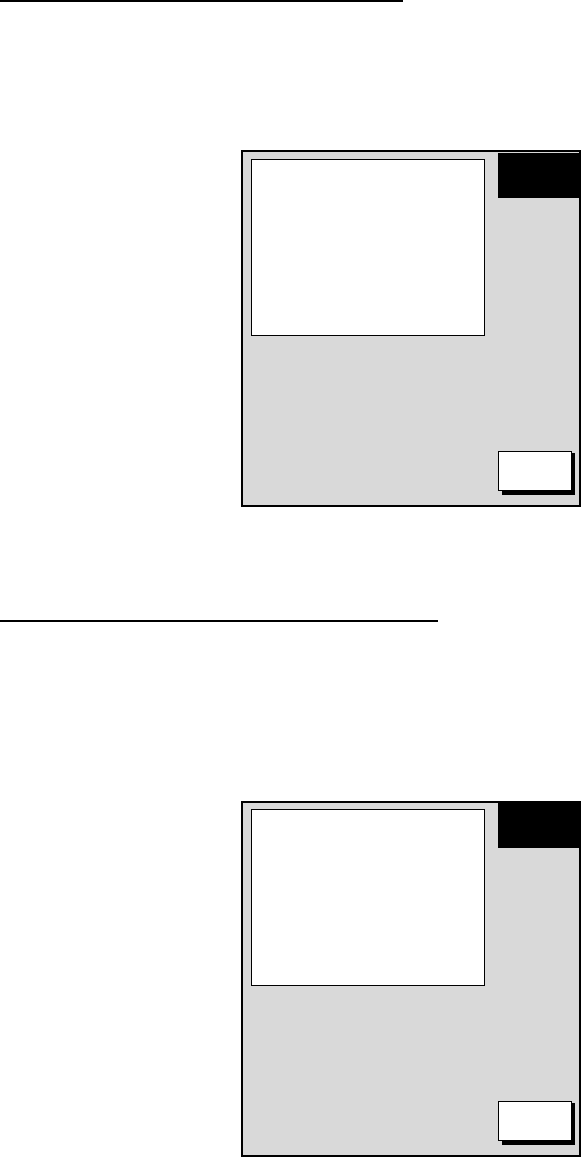
7. MAINTENANCE, TROUBLESHOOTING
7-7
GPS sensor test (blackbox GPS unit)
Press the GPS SENSOR TEST soft key at the memory I/O test menu to check
the blackbox GPS unit. The equipment displays GPS sensor program version,
and checks the GPS unit for proper operation, displaying OK or NG (No Good) as
the result. For NG request service.
PROGRAM NO. 4850217XX
GPS UNIT : OK
GPS
UNIT
RETURN
XX = Program Version No.
GPS sensor test results
ES sensor test (blackbox echo sounder)
Press the ES SENSOR TEST soft key at the memory I/O test menu to check the
blackbox echo sounder unit. The equipment displays echo sounder program
version, checks the ROM and RAM, and displays temperature and depth. The
results of the ROM and RAM check are shown OK or NG (No Good). For NG
request service.
PROGRAM NO. 02502170XX
ROM : OK
RAM : OK
TEMPERATURE :77°F
DEPTH : 4000ft
ES SNSR
TEST
RETURN
XX = Program Version No.
ES sensor test results
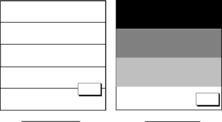
7. MAINTENANCE, TROUBLESHOOTING
7-8
7.4.3 Test pattern
The test pattern test checks the display for proper display of colors (MODEL-
1700C series) or tones (MODEL-1700 series).
1. Press the [MENU] key to show the menu.
2. Press the SYSTEM CONFIGURATION soft key.
3. Press the TEST & CLEAR soft key.
4. Press the TEST PATTERN soft key.
RETURN
GREEN
BLACK
BLUE
GREEN
RED
WHITE
PRESS 'ENTER' TO CHANGE
PATTERN.
RETURN
RETURN
MODEL-1700C series MODEL-1700 series
Test patterns
5. For the MODEL-1700C series, press the [ENTER] knob to show white, red,
green, blue and black colors.
6. Press the RETURN soft key to finish.
7. Press the [MENU] key to close the menu.
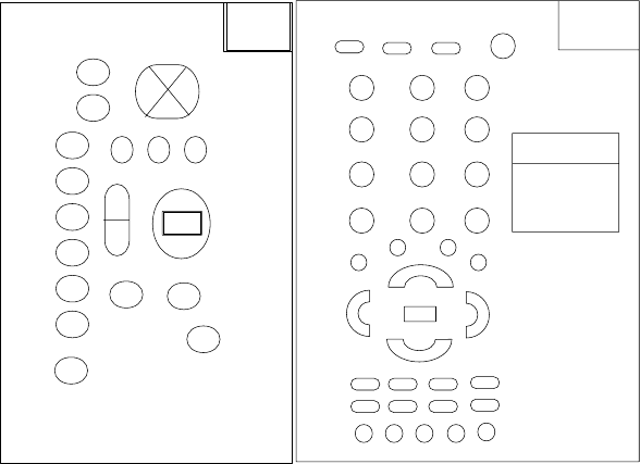
7. MAINTENANCE, TROUBLESHOOTING
7-9
7.4.4 Keyboard test
The keyboard test checks all the controls for proper operation.
1. Press the [MENU] key to show the menu.
2. Press the SYSTEM CONFIGURATION soft key.
3. Press the TEST & CLEAR soft key.
4. Press the KEYBOARD & I/R REMOTE TEST soft key.
RMTCNTL
TEST
RMTC CODE
A
523
K-BOARD
TEST
Screen for testing keyboard, remote controller
5. Operate each control on the keyboard or remote controller one by one. A key
is functioning properly if its on-screen location “lights” when the key is pressed.
The digits at the on-screen location for the [ENTER] knob on the display unit
increment upward or downward with clockwise and counterclockwise rotation
of the knob, respectively.
6. Press the [CLEAR] key three times to escape from the test.
7. Press the [MENU] key to close the menu.
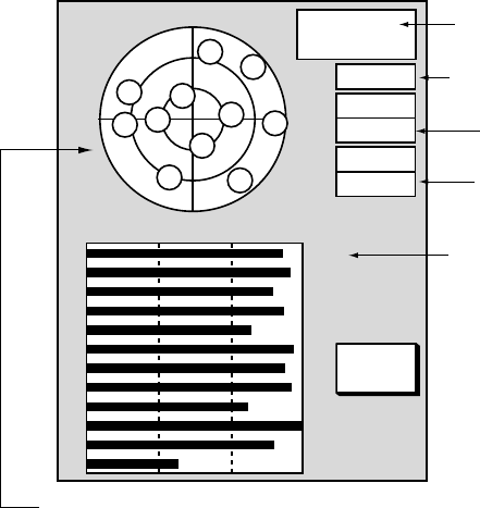
7. MAINTENANCE, TROUBLESHOOTING
7-10
7.5 GPS Monitor Display
The GPS monitor provides data about the GPS satellites.
1. Press the [DISP] key to show the plotter display.
2. Press the [MENU] key.
3. Press SYSTEM CONFIGURATION, NAV OPTIONS and GPS UNIT SETUP
soft keys to display the GPS SETUP menu.
4. Press the soft key GPS MON.
RETURN
DOP
1.2
GPS 3D
HEIGHT
22m
23:59:59
31.SEP.00
E
1
2
3
4
5
6
7
8
9
10
11
12
45
45
45
45
45
45
45
45
45
45
45
45
N
S
W
10
12
2
98
13
6
75
11
4
GPS fix state
Date
DOP value
Estimated position in the sky, and
satellite number in reverse video is
used for positioning.
Receive signal level
Bars show satellite
signal level. Satellites
extends past the
dashed line are used
in fixing position.
GPS antenna height
GPS monitor display
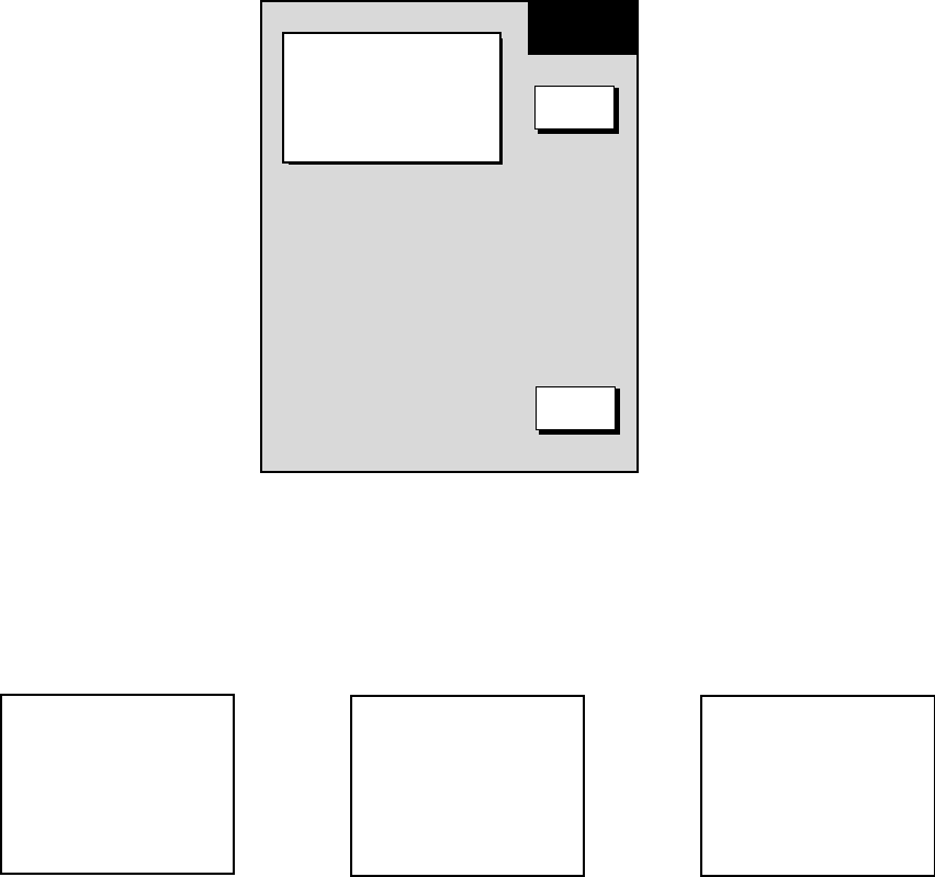
7. MAINTENANCE, TROUBLESHOOTING
7-11
7.6 Clearing Memories
Your equipment has a memory bank for each of the plotter, radar and sounder
sections. These memories can be cleared collectively or individually to start
operation afresh, with default settings.
1. Press the [MENU] key to open the menu.
2. Press the CONFIGURATION soft key.
3. Press the USER OPTION soft key.
4. Press the MEMORY CLEAR soft key.
MEMORY
CLEAR
DISPLAY UNIT CLEAR
GPS UNIT CLEAR
ES SENSOR UNIT CLEAR
RETURN
NO
NO
NO
EDIT
Memory clear menu
5. Select the memory to clear.
6. Press the EDIT soft key. One of the following displays appear.
CLEAR WPT/RTE DATA AND
MARK/LINE DATA. AND SET
DEFAULT OUT OF SOUNDER
UNIT SETTING. ARE YOU
SURE?
YES...'ENTER' KEY
NO ...'CLEAR' KEY
DISPLAY UNIT CLEAR GPS UNIT CLEAR SOUNDER UNIT CLEAR
CLEAR GPS MEMORY AND
BEGIN COLD START.
ARE YOU SURE?
YES...'ENTER' KEY
NO ...'CLEAR' KEY
SOUNDER1* : WILL SET
DEFAULT SETTING.
ARE YOU SURE?
YES...'ENTER' KEY
NO ...'CLEAR' KEY
*: ETR HOST name
Windows for clearing memory
7. Select YES and press the ENTER soft key. You are asked if you are sure to
clear the memory.
8. Push the [ENTER] knob to clear the memory.

A-1
APPENDIX
Geodetic Chart List
001: WGS84
002: WGS72
003: TOKYO : Mean Value (Japan, Korea, and Okinawa)
004: NORTH AMERICAN 1927 : Mean Value (CONUS)
005: EUROPEAN 1950 : Mean Value
006: AUSTRALIAN GEODETIC 1984 : Australia and Tasmania Island
007: ADINDAN : Mean Value (Ethiopia and Sudan)
008: : Ethiopia
009: : Mall
010: : Senegal
011: : Sudan
012: AFG : Somalia
013: AIN EL ABD 1970 : Bahrain Island
014: ANNA 1 ASTRO 1965 : Cocos Island
015: ARC 1950 : Mean Value
016: : Botswana
017: : Lesotho
018: : Malawi
019: : Swaziland
020: : Zaire
021: : Zambia
022: : Zimbabwe
023: ARC 1960 : Mean Value (Kenya, Tanzania)
024: : Kenya
025: : Tanzania
026: ASCENSION ISLAND 1958 : Ascension Island
027: ASTRO BEACON "E" : Iwo Jima Island
028: ASTRO B4 SOR. ATOLL : Tem Island
029: ASTRO POS 71/4 : St. Helena Island
030: ASTRONOMIC STATION 1952 : Marcus Island
031: AUSTRALIAN GEODETIC 1966 : Australia and Tasmania Island
032: BELLEVUE (IGN) : Efate and Erromango Islands
033: BERMUDA 1957 : Bermuda Islands
034: BOGOTA OBSERVATORY : Colombia
035: CAMPO INCHAUSPE : Argentina
036: CANTON ISLAND 1966 : Phoenix Islands
037: CAPE : South Africa
038: CAPE CANAVERAL : Mean Value (Florida and Bahama Islands)
039: CARTHAGE : Tunisia
040: CHATHAM 1971 : Chatham Island (New Zealand)
041: CHUA ASTRO : Paraguay
042: CORREGO ALEGRE : Brazil
043: DJAKARTA (BATAVIA) : Sumatra Island (Indonesia)
044: DOS 1968 : Gizo Island (New Georgia Island)
045: EASTER ISLAND 1967 : Easter Island
046: EUROPEAN 1950 (Cont'd) : Western Europe
047: : Cyprus
048: : Egypt
049: : England, Scotland, Channel, and Shetland Islands
050: : England,Ireland, Scotland, and Shetland Islands
051: : Greece
052: : Iran
053: : Italy Sardinia
054: : Italy Sicily
055: : Norway and Finland
056: : Portugal and Spain
057: EUROPEAN 1979 : Mean Value
058: GANDAJIKA BASE : Republic of Maldives
059: GEODETIC DATUM 1949 : New Zealand
060: GUAM 1963 : Guam Island
061: GUX 1 ASTRO : Guadalcanal Island
062: HJORSEY 1955 : Iceland
063: HONG KONG 1963 : Hong Kong
064: INDIAN : Thailand and Vietnam
065: : Bangladesh, India, and Nepal
066: IRELAND 1956 : Ireland
067: ISTS 073 ASTRO 1969 : Diego Garcia
068: JHONSTON ISLAND 1961 : Johnston Island
069: KANDAWALA : Sri Lanka
070: KERGUELEN ISLAND : Kerguelen Island
071: KERTAU 1948 : West Malaysia and Singapore
072: LA REUNION : Mascarene Island
073: L.C. 5 ASTRO : Cayman Brac Island
074: LIBERIA 1964 : Liberia
075: LUZON : Philippines (Excluding Mindanao Island)
076: : Mindanao Island
077: MAHE 1971 : Mahe Island
078: MARCO ASTRO : Salvage Islands
079: MASSAWA : Eritrea (Ethiopia)
080: MERCHICH : Morocco
081: MIDWAY ASTRO 1961 : Midway Island
082: MINNA : Nigeria
083: NAHRWAN : Masirah Island(Oman)
084: : United Arab Emirates
085: : Saudi Arabia
086: NAMIBIA : Namibia
087: MAPARIMA, BWI : Trinidad and Tobago
088: NORTH AMERICAN 1927 : Western United States
089: : Eastern United States
090: : Alaska
091: : Bahamas (Excluding San Salvador Island)
092: : Bahamas San Salvador Island
093: : Canada (Including Newfoundland Island)
094: : Alberta and British Columbia
095: : East Canada
096: : Manitoba and Ontario
097: : Northwest Territories and Saskatchewan
098: : Yukon
099: : Canal Zone
100: : Caribbean
101: : Central America
102: : Cuba
103: : Greenland
104: : Mexico
105: NORTH AMERICAN 1983 : Alaska
106: : Canada
107: : CONUS
108: : Mexico, Central America
109: OBSERVATORIO 1966 : Corvo and Flores Islands (Azores)
110: OLD EGYPTIAN 1930 : Egypt
111: OLD HAWAIIAN : Mean Value
112: : Hawaii
113: : Kaual
114: : Maui
115: : Oahu
116: OMAN : Oman
117: ORDNANCE SURVEY OF GREAT BRITAIN 1936 : Mean Value
118: : England
119: : England, Isle of Man, and Wales
120: : Scotland and Shetland Islands
121: : Wales
122: PICO DE LAS NIVIES : Canary Islands
123: PITCAIRN ASTRO 1967 : Pitcairn Island
124: PROVISIONAL SOUTH CHILEAN 1963 : South Chile (near 53°s)
125: PROVISIONAL SOUTH AMERICAN 1956 : Mean Value
126: : Bolivia
127: : Chile Northern Chie (near 19°s)
128: : Chile Southern Chile (near 43°s)
129: : Colombia
130: : Ecuador
131: : Guyana
132: : Peru
133: : Venezuela
134: PUERTO RICO : Puerto Rico and Virgin Islands
135: QATAR NATIONAL : Qatar
136: QORNOQ : South Greenland
137: ROME 1940 : Sardinia Islands
138: SANTNA BRAZ : Sao Maguel, Santa Maria Islands (Azores)
139: SANTO (DOS) : Espirito Santo Island
140: SAPPER HILL 1943 : East Falkland Island
141: SOUTH AMERICAN 1969 : Mean Value
142: : Argentina
143: : Bolivia
144: : Brazil
145: : Chile
146: : Colombia
147: : Ecuador
148: : Guyana
149: : Paraguay
150: : Peru
151: : Trinidad and Tobago
152: : Venezuela
153: SOUTH ASIA : Singapore
154: SOUTHEAST BASE : Porto Santo and Medeira Islands
155: SOUTHWEST BASE : Faial, Graciosa, Pico, Sao Jorge, and Terceira Islands
156: TIMBALAI 1948 : Brunel and East Malaysia (Sarawak and Sadah)
157: TOKYO : Japan
158: : Korea
159: : Okinawa
160: TRISTAN ASTRO 1968 : Tristan da Cunha
161: VITI LEVU 1916 : Viti Levu Island (Fiji Islands)
162: WAKE-ENIWETOK 1960 : Marshall Islands
163: ZANDERIJ : Suriname
164: BUKIT RIMPAH : Bangka and Belitung Islands (Indonesia)
165: CAMP AREA ASTRO : Camp Mcmurdo Area, Antarctica
166: G. SEGARA : Kalimantan Islands(Indonesia)
167: HERAT NORTH : Afghanistan
168: HU-TZU-SHAN : Taiwan
169: TANANARIVE OBSERVATORY 1925 : Madagascar
170: YACARE : Uruguay
171: RT-90 : Sweden
172 : Pulkovo 1942 : Russia
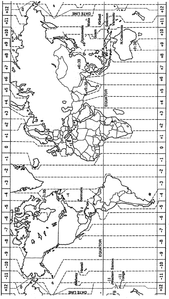
APPENDIX
A-2
World Time Chart
APPENDIX
A-3
Icons
Icon Meaning
North marker. Shows North in course-up and automatic course-up modes.
Correct chart and suitable scale - full chart reliability.
Chart overenlarged.
• Chart card not inserted.
• Wrong chart card inserted.
• Chart scale too small.
Alarm setting violated.
Track is not being recorded or plotted.
Chart offset applied.
S A
V E
Voyage-based route’s waypoints are being entered manually.
Latitude and longitude position offset applied.
Voltage of battery on circuit board in display unit is low. Contact your dealer
about replacement.

SP - 1
SPECIFICATIONS OF MARINE RADAR
MODEL 1722/1732/1742/1762
MODEL 1722C/1732C/1742C/1762C
1. GENERAL
(1) Indication System
M1722/1732/1742/1762 PPI Daylight display, raster scan, 4 tones monochrome LCD
M1722C/1732C/1742C/1762C PPI Daylight display, raster scan, color LCD
(2) Range, Pulse length (PL) & Pulse Repetition Rate (PRR)
Range (nm) Pulse length (µs) PRR (Hz approx.)
0.125 to 1.5 0.08 2100
1.5 to 3 0.3 1200
3 to 48* 0.8 600
*Maximum Range: M1722/C: 24nm, M1732/C: 36nm, M1742/C: 36nm, M1762/C: 48nm
(3) Range Resolution 29 m
(4) Bearing Resolution M1722/C: 6.7º, M1732/C: 5.5º, M1742/C: 5.0º, M1762/C: 3.9º
(5) Minimum Range 41 m
(6) Bearing Accuracy ±1º
(7) Range Ring Accuracy 0.9 % of range or 8 m, whichever is the greater
2. SCANNER UNIT
MODEL1722/C:
(1) Radiator Micro-strip
(2) Polarization Horizontal
(3) Antenna Rotation Speed 23 rpm nominal
(4) Radiator Length 45 cm
(5) Horizontal Beamwidth less than 5.2°
(6) Vertical Beamwidth 25°
(7) Sidelobe Attenuation less than -20 dB
MODEL1732/C:
(1) Radiator Printed waveguide array
(2) Polarization Horizontal
(3) Antenna Rotation Speed 24 rpm nominal
(4) Radiator Length 60 cm
(5) Horizontal Beamwidth less than 4°
(6) Vertical Beamwidth 20°
(7) Sidelobe Attenuation less than -18 dB
SP - 2
MODEL1742/C:
(1) Radiator Slotted waveguide array
(2) Polarization Horizontal
(3) Antenna Rotation Speed 24 rpm nominal
(4) Radiator Length 60 cm
(5) Horizontal Beamwidth less than 3.5°
(6) Vertical Beamwidth 30°
(7) Sidelobe Attenuation less than -20 dB
MODEL1762/C:
(1) Radiator Slotted waveguide array
(2) Polarization Horizontal
(3) Antenna Rotation Speed 24 rpm nominal
(4) Radiator Length 100 cm
(5) Horizontal Beamwidth less than 2.4°
(6) Vertical Beamwidth 27°
(7) Sidelobe Attenuation less than -24 dB
3. TRANSCEIVER MODULE
(1) Frequency and Modulation 9410 MHz ±30MHz (X band), P0N
(2) Peak Output Power M1722/1742/1722C/1742C: 2 kW nominal,
M1732/1762/1731C/1762C: 4 kW nominal
(3) Modulator FET Switching Method
(4) Intermediate Frequency 60 MHz
(5) Tuning Automatic
(6) Receiver Front End MIC (Microwave IC)
(7) Bandwidth 7 MHz
(8) Duplexer Circulator with diode limiter
(9) Warming up M1722/1722C: 60 sec. approx.
M1732/1742/1762(C): 90 sec. approx.
4. DISPLAY UNIT
(1) Picture Tube
M1722 /1732/1742/1762 7 inch rectangular monochrome LCD
240(H) x 320(V) dots, Effective radar display area: 240 x 240 dots
M1722C/1732C/1742C/1762C 6.5 inch rectangular color LCD
234(H) x 320(V) dots, Effective radar display area: 234 x 234 dots
(2) Range, Range Ring Interval, Number of Rings

SP - 3
Range (NM) 0.125 0.25 0.5 0.75 1 1.5 2 3 4 6 8 12 16 24 36 48
Ring Interval (NM) 0.0625 0.125 0.125 0.25 0.25 0.5 0.5 1 1 2 2 3 4 6 6 4
Number of Rings 2 2 4 3 4 3 4 3 4 3 4 4 4 4 6 12
Maximum range: M1722/C: 24nm, M1732/1742(C): 36nm, M1762/C: 48nm
(4) Markers Heading Line, Bearing Scale, Range Rings,
Variable Range Marker (VRM), Electronic Bearing Line (EBL),
Alarm Zone, Waypoint Mark (navigation input required)
(5) Alphanumeric Indications Range, Range Ring Interval, Interference Rejection (IR),
Variable Range Marker (VRM), Electronic Bearing Line (EBL),
Stand-by (ST-BY)
Guard Alarm (G(IN), G(OUT)), Echo Stretch (ES),
Range and Bearing to Cursor, L/L Position*, Echo Tailing (TRAIL),
Trailing Time, Watchman (WATCHMAN),
Ship’s speed* (SPD), Ship’s Course*
Water temperature**, Water depth**
*: Navigation data required, **: Echo sounder data required
(6) Input Data IEC 61162-1/ NMEA 0183 Ver.1.5
Own ship’s position: GGA>RMC>RMA>GLL
Ship’s speed: RMC>RMA>VTG>VHW
Bearing (True): HDT>HDG*1>HDM*1>VHW
Bearing (Magnetic): HDM>HDG*1>HDT*1>VHW
Course: RMC>RMA>VTG
Waypoint (Range, Bearing): RMB>WPL>BWR>BWC
Loran time difference: RMA>GLC>GTD
Water depth: DPT>DBT>DBS>DBK
Wind: MWV>VWT>VWR
Water Temperature: MTW
Time: ZDA
*1: calculated by magnetic deviation
(7) Output Data
Alarm signal 12 VDC, 100 mA or less
5. PLOTTER FUNCTION
(1) Projection Mercator
(2) Usable Area 85° latitude or below
(3) Effective Area 133.4 x 97.3 mm
(4) Display pixels 234 x 320 dots
(5) Position Indication Latitude/longitude, Loran C LOP or DECCA LOP
SP - 4
(6) Effective Projection Area 0.125 nm to 1,024 nm (at equatorial area)
(7) Track Display Plot interval: by time (0 to 99 min. 59 sec.) or
by distance (0 to 99.9 nm)
(8) Colors Red, yellow, green, purple, light-blue, blue, white
(9) Memory Capacity Track/mark: 8000 points, Waypoint: 999 points
(10) Storage Capacity Simple route: 200 routes with 35 waypoints each
(11) MOB 1 point
(12) Quick Routes 1 course with 35 waypoints max.
(13) Electronic Chart FURUNO chart card or NAVIONICS chart card available
C-MAP chart card also available for C-MAP NT Model
(14) Alarms Arrival and Anchor watch, Cross track error and proximity alarms,
Ship’s speed in and out alarms, Water temperature, Trip alarm
5. POWER SUPPLY
(1) Rated Voltage/Current
M1722 12-24 VDC: 3.7-1.8 A
M1732 12-24 VDC: 3.8-1.9 A
M1742 12-24 VDC: 3.9-2.0 A
M1762 12-24 VDC: 4.2-2.1 A
M1722C 12-24 VDC: 4.4-2.2 A
M1732C 12-24 VDC: 4.5-2.3 A
M1742C 12-24 VDC: 4.6-2.3 A
M1762C 12-24 VDC: 4.9-2.4 A
(2) Rectifier (PR-62: option) 100/110/115/200/220/230 VAC, 1 phase, 50/60 Hz
6. ENVIRONMENTAL CONDITION
(1) Ambient Temperature Scanner Unit: -25°C to +70°C
(IEC 60945) Display Unit: -15°C to +55°C
(2) Relative Humidity 93 % or less at +40°C
(3) Waterproofing Scanner Unit: IPX6
(IEC 60529) Display Unit: IPX5
(4) Bearing Vibration IEC 60945
7. COATING COLOR
(1) Display Unit N3.0
(2) Scanner Unit
M1722/1732 (C) N9.5 (upper), 2.5PB3.5/10 (lower)
M1742/1762 (C) N9.5
SP - 5
8. COMPASS SAFE DISTANCE
(1) Display Unit
M1722/1732/1742/1762 Standard: 0.90 m Steering: 0.60 m
M1722C/1732C/1742C/1762C
Standard: 0.90 m Steering: 0.60 m
(2) Scanner Unit
M1722/C Standard: 1.25 m Steering: 0.85 m
M1732/C Standard: 1.40 m Steering: 1.10 m
M1742/C Standard: 2.10 m Steering: 1.60 m
M1762/C Standard: 1.00 m Steering: 0.75 m