Furuno USA 9ZWRTR059A Marine Radar User Manual
Furuno USA Inc Marine Radar
UserManual.wiki
>
Furuno USA
>
9ZWRTR059A User Manual
>
inst manual
Contents
1.
op man part 1
2.
op man part 2
3.
op man part 3
4.
inst manual
inst manual
Navigation menu
Upload a User Manual
Namespaces
Wiki Guide
HTML
PDF
Info
Views
User Manual
Discussion / Help
Navigation
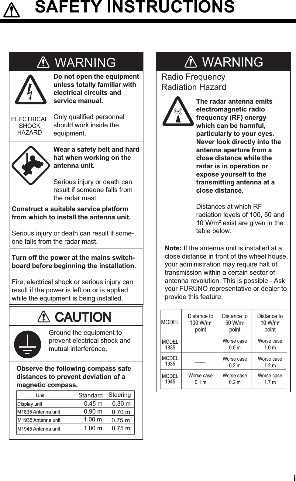

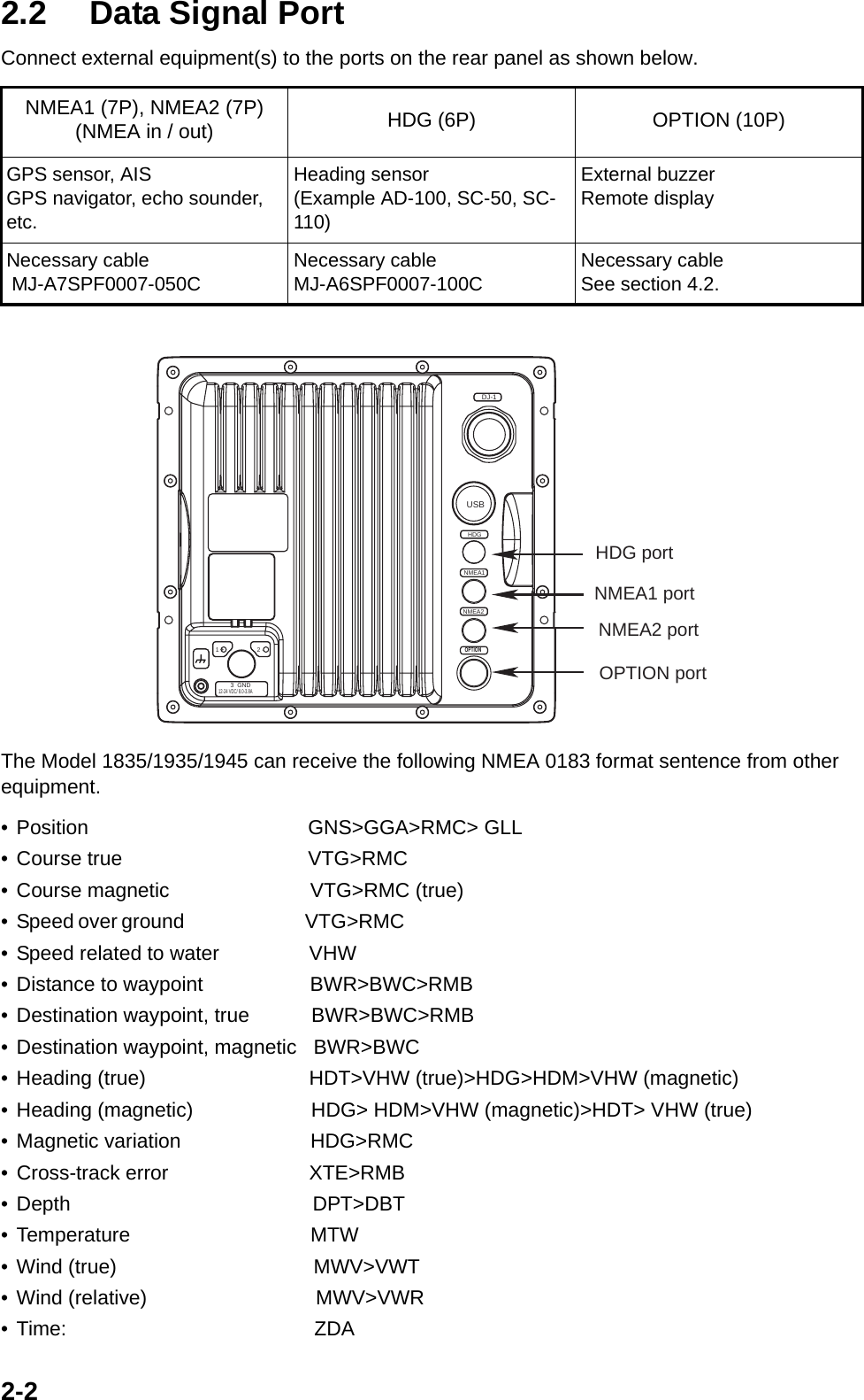
![3-23.2 How to Set the PurposeSet the purpose of the radar. 1. Press the MENU key. The main menu appears on the screen.2. Press T or S on the cursor pad to select Factory. The factory menu title bar appears in gray on the right of the screen.3. While you press the CANCEL/HL OFF key, press the MENU key five times to activate the Factory menu.4. Press the ENTER key. The Factory menu becomes active and the cursor moves to the right column.5. Press T or S to select the Purpose.6. Press the ENTER key to show the setting window.7. Press T or S to select an option.8. Press the ENTER key to validate the setting.9. Press the CANCEL/HL OFF key to return to the main menu.[ENTER]: Enter [CANCEL/HL OFF]: Back[MENU]: ExitSystemGPSUnitsTargetARPAAISModel Language Purpose : 1835 RTR-057A*: English: SeaMenuMenuFactoryFactoryInitialFactorySector Blank InstallationTests*: The model name depends on your radar model. Do not change the model name. RiverSeaIECRussian-River](https://usermanual.wiki/Furuno-USA/9ZWRTR059A.inst-manual/User-Guide-1456330-Page-28.png)
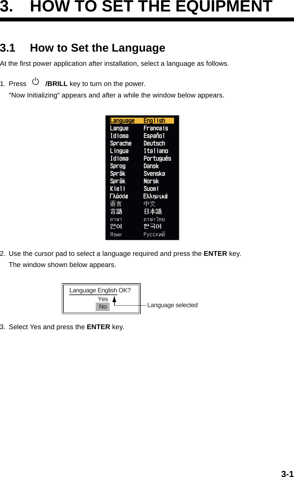
![3-33.3 How to Enter the Initial SettingsAfter you set the purpose of the radar, enter the initial settings as follows.1. On the main menu, press T or S to select Installation. 2. Press the ENTER key. The Installation menu becomes active and the cursor moves to the right column.3. Press T or S to select an item from the Installation menu.4. Press the ENTER key to show the setting window.5. Press T or S to select an option.6. Press the ENTER key to validate the setting.7. Press the MENU key to close the main menu.Basic SettingsInput Source: Select the input source from Master and Slave. The default setting is Master. Master: A display unit operates as the main radar. Slave: A display unit operates as a remote display. For the remote display, make sure you adjust the "Video Init Adjust" and "Timing Adjust" (page 3-5 and 3-6).ARPA QV Select: Set to "On" position to display quantized video on the screen. Set to "Off" po-sition for normal use.Demo Mode: Set to "On" position to activate the demo mode. Set to "Off" position for normal use.[ENTER]: Enter [CANCEL/HL OFF]: Back[MENU]: ExitSystemGPSUnitsTargetARPAAISDemo ModeInput SourceARPA QV SelectAntenna HeightHeading Adjust: 15m: 2: 0. 0 °: Off: Master: OffMBS Adjust*Auto Install Setup*Timing AdjustNear STC Level: 0: 0: 0.000 NMMenuMenuInstallationInstallationInitialFactorySector Blank **InstallationTotal On Time* : 000000.5 hTotal TX Time* : 000000.6 h* : Displayed when scrolled.Memory Clear*** : Set the Sector Blank to "Off" in order to execute Auto Installation Setup in the Installation menu.Video Init Adjust* : 6ARPA Adjust SP* : 2ARPA Adjust MP* : 2ARPA Adjust LP* : 2Antenna Rotation : RotateTestsA/C Auto Adjust](https://usermanual.wiki/Furuno-USA/9ZWRTR059A.inst-manual/User-Guide-1456330-Page-29.png)
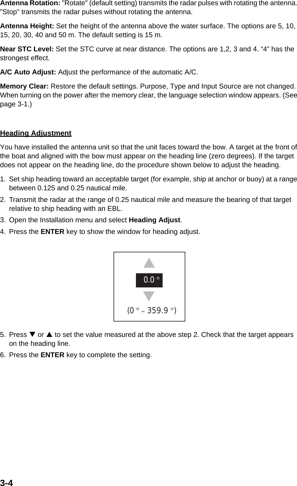
![NAME OUTLINE Q'TYDESCRIPTION/CODE №PACKING LIST03HD-X-9852 -1 RDP-152-1835-E/C、RDP-152-1935-E/C、RDP-152-1945-E/C1/1NAME OUTLINE Q'TYDESCRIPTION/CODE №ユニット UNIT指示部DISPLAY UNIT1**RDP-152-1835/19**-E/C000-014-616-00予備品 SPARE PARTS予備品SPARE PARTS1SP03-12200000-086-965-00付属品 ACCESSORIES付属品ACCESSORIES1FP03-11601001-058-470-00工事材料 INSTALLATION MATERIALSCP03-32900ケーブル組品MJCABLE ASSY.1MJ-A3SPF0017-050ZC000-157-995-10工事材料INSTALLATION MATERIALS1CP03-32901001-058-460-00図書 DOCUMENTヒューズ変更のお願いNOTICE FOR FUSE REPLACEMENT1J39-60060-*000-807-986-1*J39-60060-*000-172-409-1*フラッシュマウント用型紙FLUSH MOUNTING TEMPLATE1C32-00802000-170-325-1*C32-00802-*000-172-410-1*取扱説明書OPERATOR'S MANUAL1OME-35790-*000-170-245-1*OME-35790-*000-172-398-1*操作要領書OPERATOR'S GUIDE1MLG-35790-*000-170-254-1*MLG-35790-*000-172-400-1*装備要領書INSTALLATION MANUAL1IME-35790-*000-170-251-1*IME-35790-*000-172-402-1*コ-ド番号末尾の[**]は、選択品の代表コードを表します。CODE NUMBER ENDING WITH "**" INDICATES THE CODE NUMBER OF REPRESENTATIVE MATERIAL.(略図の寸法は、参考値です。 DIMENSIONS IN DRAWING FOR REFERENCE ONLY.) 03HD-X-9852型式/コード番号が2段の場合、下段より上段に代わる過渡期品であり、どちらかが入っています。 なお、品質は変わりません。TWO TYPES AND CODES MAY BE LISTED FOR AN ITEM. THE LOWER PRODUCT MAY BE SHIPPED IN PLACE OF THE UPPER PRODUCT. QUALITY IS THE SAME.A-1](https://usermanual.wiki/Furuno-USA/9ZWRTR059A.inst-manual/User-Guide-1456330-Page-37.png)
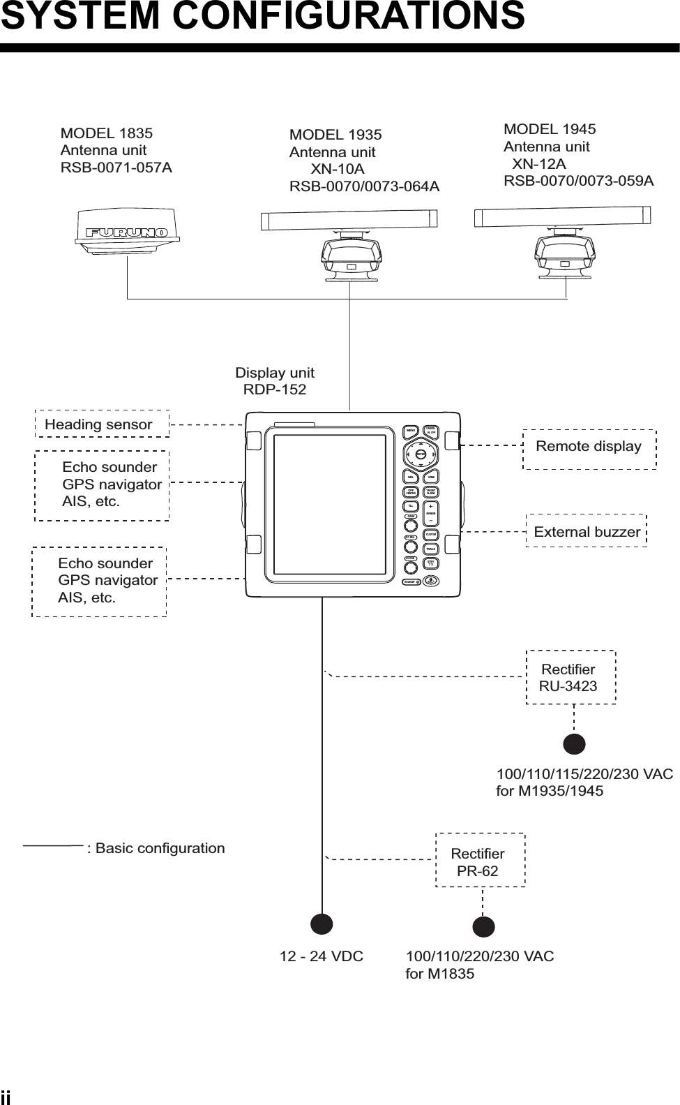
![123WHTBLKクロシロ10A:12V5A:24V123(+)(-)56IV-2sq.*112-24 VDC MJ-A3SPF0017-050ZC,5m,φ10DPYC-1.5100/110/220/230VAC1φ,50/60Hz*1MJ-A3SPFRECTIFIER整流器PR-62 *2*4243A1BCDRAWNCHECKEDAPPROVEDDWG.No.TITLENAME名称INTERCONNECTION DIAGRAM相互結線図REF.No.SCALE MASS kgT.YAMASAKIMODEL 1835船舶用レーダーMARINE RADAR注記*1)造船所手配。*2)オプション。*3)シールドは両ユニットで完全に接地すること。NOTE*1: SHIPYARD SUPPLY.*2: OPTION.*3: SHIELD SHOULD BE GROUNDED EFFECTIVELY AT BOTH END.*4)工場出荷時10A。24V使用時は5Aヒューズに交換する。(+)(-)GNDDJ-1+12V+12V-12V-12VP/L_AP/L_B1011201415287シロ/ダイ(太)シロ/チャ(太)シロ/アカ(太)シロ/ミドリ(太)シロ/クロ(太)チャムラサキアオ BLUPPLBRNWHT/BLK[B]WHT/GRN[B]WHT/RED[B]WHT/BRN[B]WHT/ORG[B]GND+12V+12V-12V-12VP/L_AP/L_BU2B2J801(VH9P)12345678911754シロシロ/アオ(太)クロモモ(太)VIDEOGND621ドウジクキCOAX.YELPNK[B]BLKWHT/BLU[B]WHTVIDEOGND9NC123411121322 アカ RED SPARE183MBS-L24GNDミドリダイハイGRNGRYORG MBS-LGNDU2B3 IF-9214J611(NH13P)159 NCNCNC104NCNCNCNC23678HDANTENNA UNITRSB-0071空中線部*3 *3(RW-8577,17C+2C2V,MAX.30m)MJ-B24LPF0002,10/15/20/30m,φ11.51234USBPC(FOR MAINTENANCE)VBUSGNDTX_TRIGTX_TRIGTUNING_IND TUNING_INDTUNING_CONTTUNING_CONTJ802(VH4P)SHIELDD_MD_P12345678910MJ-A10SPFOP_BPOP_VIDEO_GNDSHIELDOP_HDOP_TRIGOP_VIDEOEXT_BUZZEXT_BUZZ_12VGNDNC10*2MJ-B24LPF0010MAX.30m,φ10MOTOR-HMOTOR-CHDBP2319EXT_TRIGMOTOR-HMOTOR-HMOTOR-C16+12V-12V1213*4: DEFAULT:10A. REPLACE FUSE TO 5A FOR 24V USE.03-176-6001-0B TYPE123456NC1234567HDG+12VGND1234567+12VGNDNMEA 1NMEA 2DATA-HDATA-CSHIELDMJ-A6SPFMJ-A7SPFMJ-A7SPFIV-2sq.*1TD1-ATD1-BSHIELDTD2-ATD2-BSHIELDCLK-HCLK-CWHTBLKクロシロキミドリYELGRN*2RD2-HRD2-CRD1-HRD1-C12-24VDCOPTIONMOTOR-HMOTOR-CBPT.TAKENO*2RDP-152指示部DISPLAY UNIT10m0.2mMJ-A10SPFW0001+R副指示器 *2REMOTE DISP.BLKREDアカクロOP03-21EXT. BUZZER外部ブザーBLKREDアカクロ7*2MD-9208MJ-A7SPF0007,5m*2同上DITTODATA-HDATA-CCLK-HCLK-CSHIELDAD-100 *2PG-1000SC-50 ETC.AD-10 FORMAT*2AD-100PG-1000ORSC-50 ETC.TD-ATD-BSHIELDNMEA0183*2*2MJ-A6SPF0007,10mMJ-A6SPF0007,10mMJ-A6SPF0003,5/10mC3579-C01- C3/Sep/093/Sep/09MJ-A7SPF0007-050C,5m,φ6GPS受信機GPS RECEIVERGP-320B/330B*2または ORDST-800スマートセンサーSMART SENSOR+12VGNDSHIELDTD-ATD-BRD-HRD-CキミドリシロアオアカクロYELGRNWHTBLUREDBLKEXT. EQUIPMENT外部機器DR-100DM-200ETC.25/Sep/09 R.EsumiS-1](https://usermanual.wiki/Furuno-USA/9ZWRTR059A.inst-manual/User-Guide-1456330-Page-45.png)
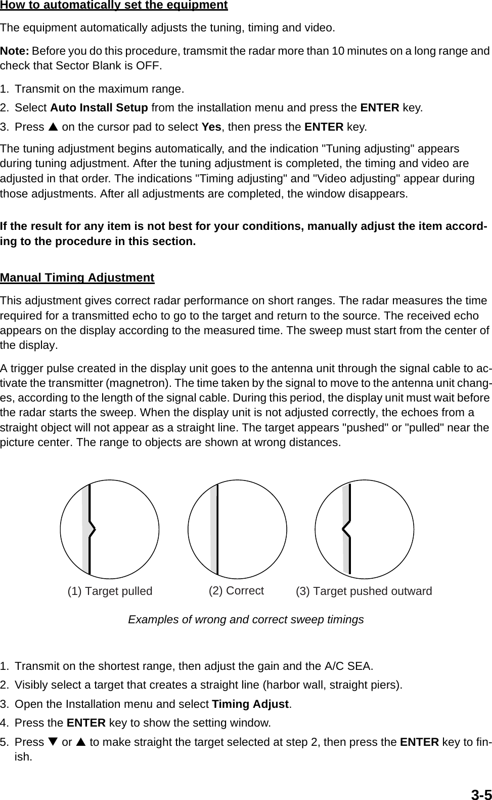
![123WHTBLKクロシロ10A:12V5A:24V(+)(-)IV-2sq.*112-24 VDC MJ-A3SPF0017-050ZC,5m,φ10 MJ-A3SPF*4243A1BCDRAWNCHECKEDAPPROVEDDWG.No.TITLENAME名称REF.No.SCALE MASS kgT.YAMASAKI注記*1)造船所手配。*2)オプション。*3)シールドは両ユニットで完全に接地すること。NOTE*1: SHIPYARD SUPPLY.*2: OPTION.*3: SHIELD SHOULD BE GROUNDED EFFECTIVELY AT BOTH END.*4)工場出荷時10A。24V使用時は5Aヒューズに交換する。*4: DEFAULT: 10A. REPLACE FUSE TO 5A FOR 24V USE.5612(+)(-)GND整流器RU-3423 *2RECTIFIERGNDDJ-1+12V+12V-12V-12VP/L_AP/L_B1011201415287チャ BRNGND+12V+12V-12V-12VP/L_AP/L_B123456789NCANTENNA UNIT空中線部RSB-0070/0073(24/48rpm)J821(VH9P)TX_TRIGTX_TRIGキ(太)クロ(太)アカ(太)シロ(太)チャ(太)アオミドリYEL[B]BLK[B]RED[B]WHT[B]BRN[B]BLUGRN121312ミドリ(太)ダイ(太)GRN[B]ORG[B]VIDEOGND621ドウジクキCOAX.YELVIDEOGND111213183MBS-L24GNDMBS-LGND159 NCNC104NCNC2367803P9249U2B622 ムラサキ PPLシロ/アカ WHT/RED41923J824(NH13P)91175シロクロ BLKWHT 1234HDJ823(VH4P)アオ(太)ムラサキ(太)BLU[B]PPL[B]*3 *3シロ/チャ WHT/BRNアカ REDダイ ORGシロ/ダイ WHT/ORG16TUNING_CONT TUNING_CONTTUNING_INDTUNING_INDJ822(VH2P)NCNC1234USBPC(FOR MAINTENANCE)VBUSGND(RW-6537,21C+2C2V,MAX.30m)D_MD_P12345678910MJ-A10SPFOP_BPOP_VIDEO_GNDSHIELDOP_HDOP_TRIGOP_VIDEOEXT_BUZZEXT_BUZZ_12VGNDNC+12V-12VBPHDMOTOR-HMOTOR-CMOTOR-CMOTOR-HMOTOR-HEXT_TRIG03-176-6002-0MJ-B24LPF0005,5/10/15/20/30m,φ14.5RW-47470.3mB TYPE12345612345671234567IV-2sq.*1NCHDG+12VGND+12VGNDNMEA 1NMEA 2DATA-HDATA-CSHIELDTD1-ATD1-BSHIELDTD2-ATD2-BSHIELDCLK-HCLK-CMJ-A6SPFWHTBLKクロシロキミドリYELGRNRD1-HRD1-CRD2-HRD2-COPTION12-24VDC*2RDP-152指示部DISPLAY UNITBPMOTOR-HMOTOR-CMOTOR-CMOTOR-HMOTOR-HT.TAKENOMJ-A7SPFMJ-A7SPF10m同上DITTO10*2MJ-B24LPF0010MAX.30m,φ10*20.2mMJ-A10SPFW0001+R副指示器 *2REMOTE DISP.BLKREDアカクロOP03-21EXT. BUZZER外部ブザーBLKREDアカクロ7*2MJ-A7SPF0007,5m*2DATA-HDATA-CCLK-HCLK-CSHIELDAD-100 *2PG-1000SC-50 ETC.AD-10 FORMAT*2AD-100PG-1000ORSC-50 ETC.TD-ATD-BSHIELDNMEA0183*2*2MJ-A6SPF0007,10mMJ-A6SPF0007,10mMJ-A6SPF0003,5/10mDPYC-1.5*1100/110/220/230VAC1φ,50/60HzC3580-C01- CMODEL 1935/1937/1945船舶用レーダー相互結線図MARINE RADARINTERCONNECTION DIAGRAM3/Sep/093/Sep/09GPS受信機GPS RECEIVERGP-320B/330B*2または ORDST-800スマートセンサーSMART SENSORMJ-A7SPF0007-050C,5m,φ6+12VGNDSHIELDTD-ATD-BRD-HRD-CキミドリシロアオアカクロYELGRNWHTBLUREDBLKEXT. EQUIPMENT外部機器DR-100DM-200ETC.25/Sep/09 R.EsumiS-2](https://usermanual.wiki/Furuno-USA/9ZWRTR059A.inst-manual/User-Guide-1456330-Page-46.png)