Furuno USA 9ZWRTR070 MARINE RADAR User Manual OPERATORS MANUAL PART 1
Furuno USA Inc MARINE RADAR OPERATORS MANUAL PART 1
Contents
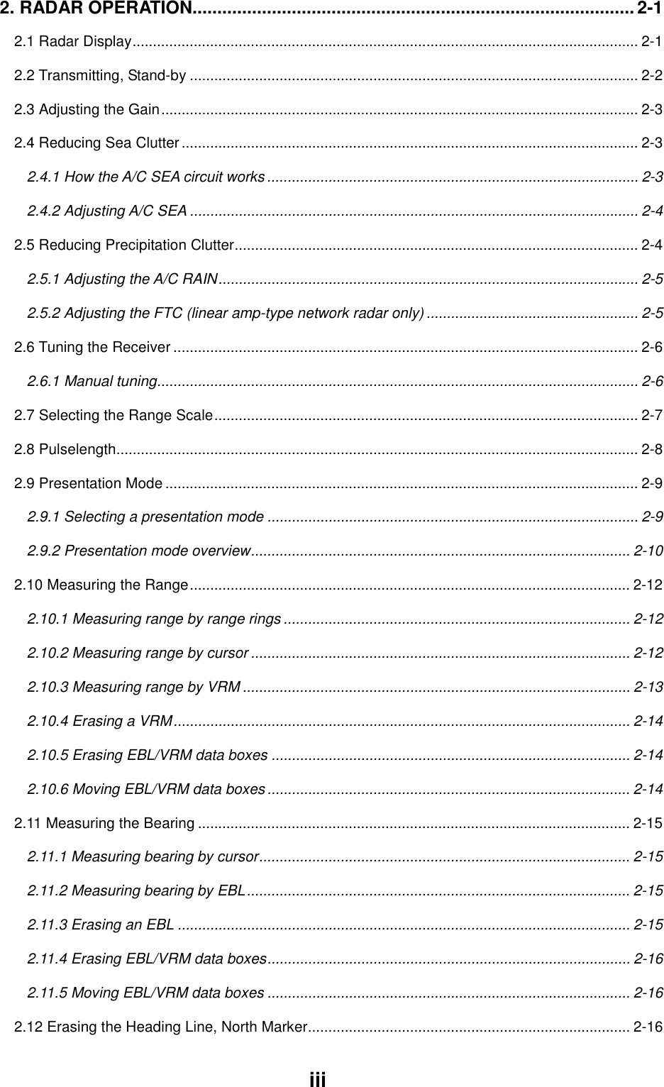
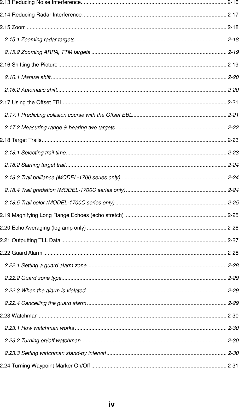
- 1. OPERATORS MANUAL PART 1
- 2. OPERATORS MANUAL PART 2
- 3. OPERATORS MANUAL PART 3
- 4. OPERATORS MANUAL PART4
OPERATORS MANUAL PART 1

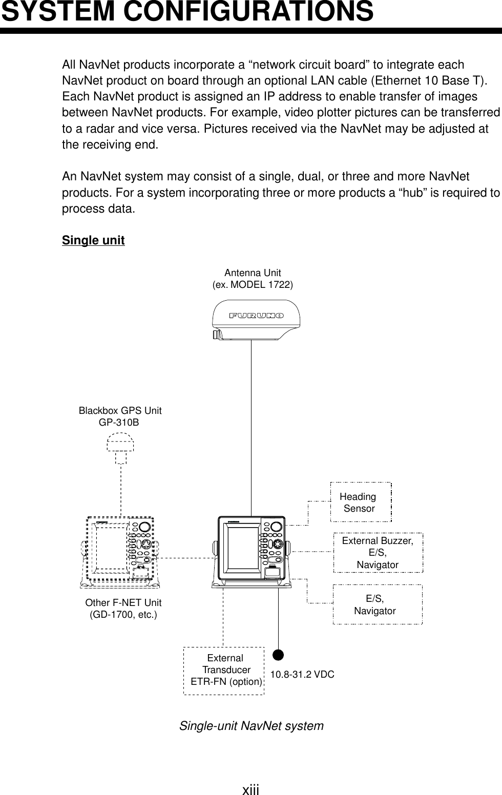
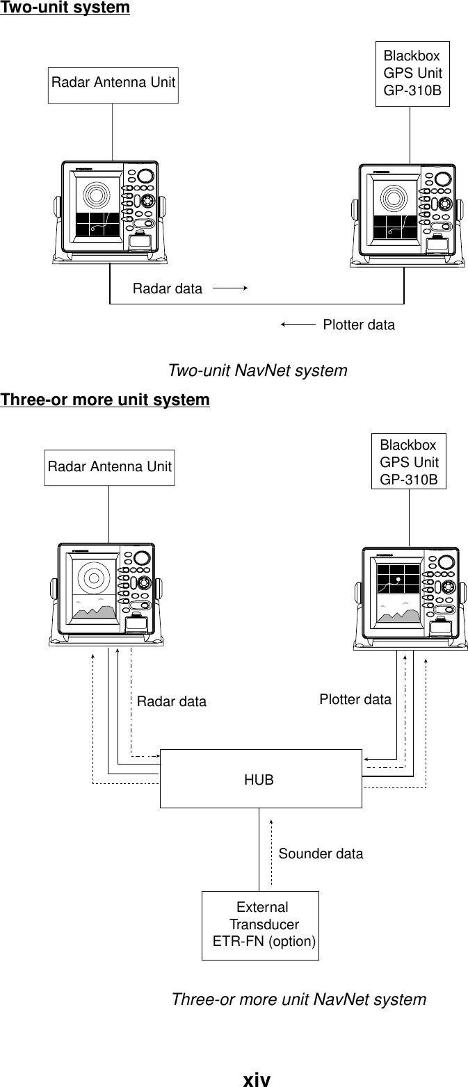
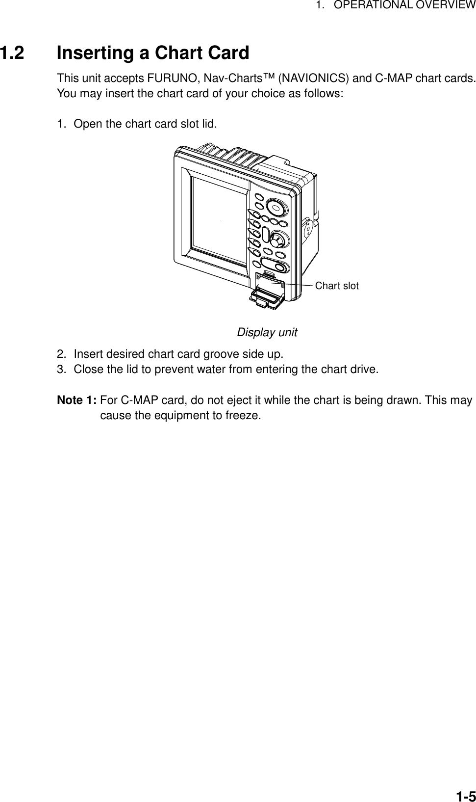
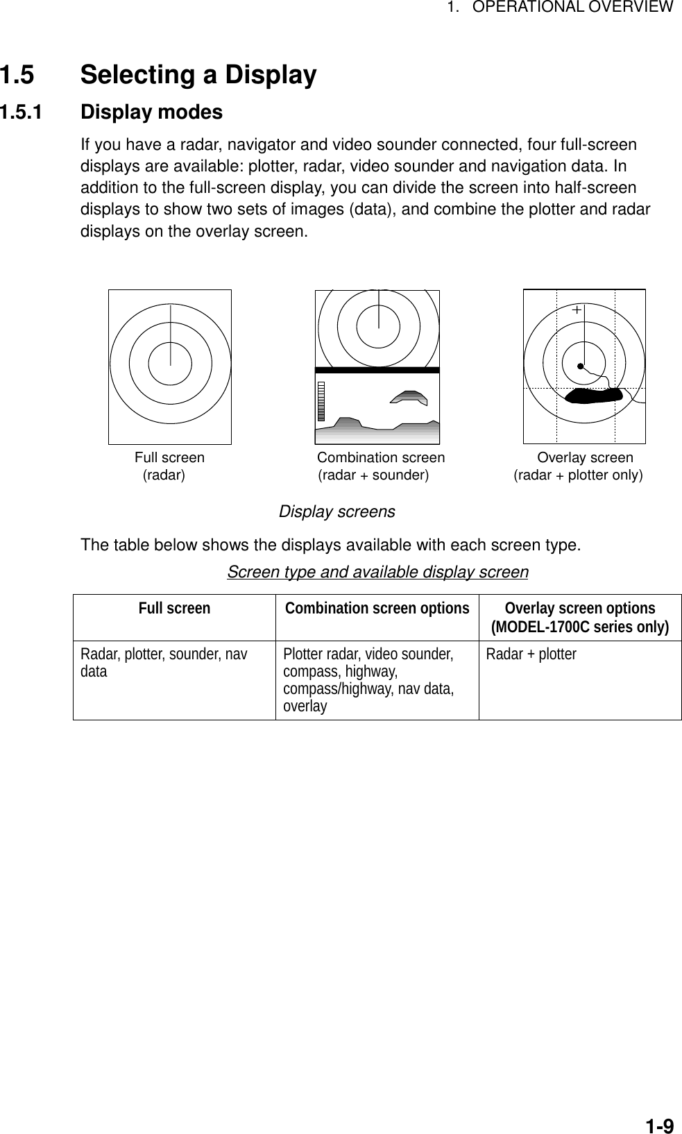
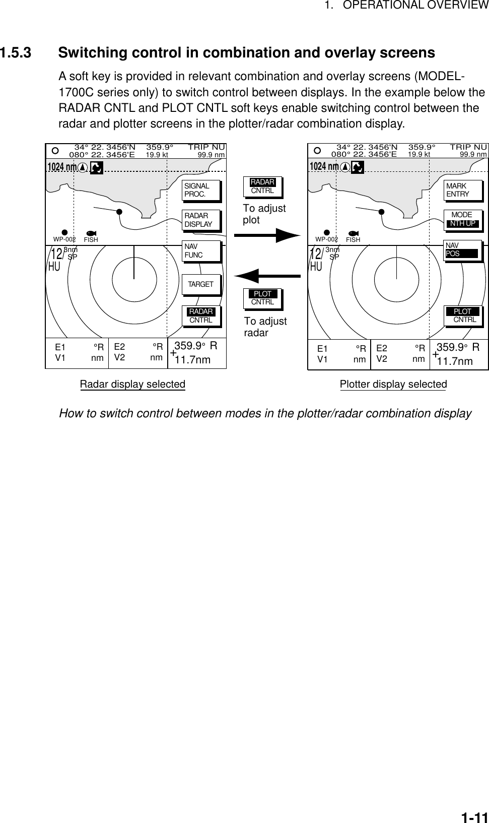
![iiTABLE OF CONTENTSFOREWORD............................................................................................................ xiSYSTEM CONFIGURATIONS ............................................................................... xiii1. OPERATIONAL OVERVIEW .............................................................................1-11.1 Operating Controls .................................................................................................................... 1-21.1.1 Control overview ................................................................................................................. 1-21.1.2 Soft keys.............................................................................................................................. 1-31.1.3 [ENTER] knob ..................................................................................................................... 1-41.2 Inserting a Chart Card............................................................................................................... 1-51.3 Turning the Unit On/Off ............................................................................................................. 1-61.4 Adjusting Display Brilliance, Panel Brilliance, Contrast, Hue.................................................... 1-71.4.1 Display brilliance, panel brilliance....................................................................................... 1-71.4.2 Contrast............................................................................................................................... 1-81.4.3 Hue (MODEL-1700C series only) ....................................................................................... 1-81.5 Selecting a Display.................................................................................................................... 1-91.5.1 Display modes..................................................................................................................... 1-91.5.2 Selecting a display ............................................................................................................ 1-101.5.3 Switching control in combination and overlay screens ......................................................1-111.5.4 Selecting image source..................................................................................................... 1-121.6 Entering the MOB Mark, Setting MOB as Destination ............................................................ 1-131.7 Data Boxes.............................................................................................................................. 1-141.7.1 Showing, hiding data boxes with soft key ......................................................................... 1-141.7.2 Rearranging data boxes....................................................................................................1-141.7.3 Temporarily erasing a data box......................................................................................... 1-141.8 Soft Keys................................................................................................................................. 1-151.8.1 Executing a function.......................................................................................................... 1-151.9 Demonstration Display............................................................................................................ 1-16](https://usermanual.wiki/Furuno-USA/9ZWRTR070.OPERATORS-MANUAL-PART-1/User-Guide-132136-Page-4.png)
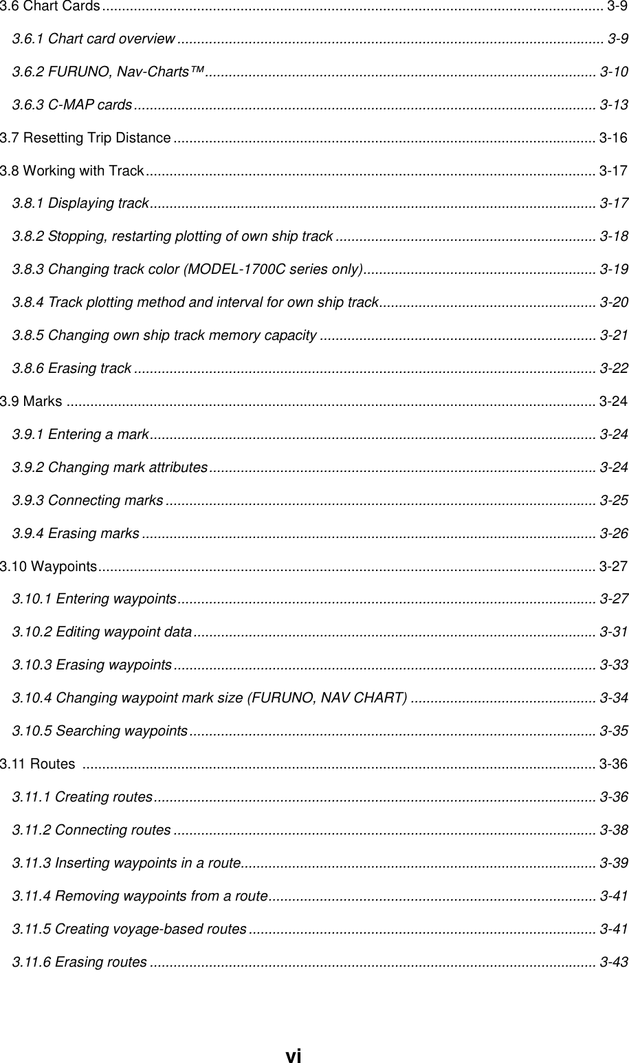
![1. OPERATIONAL OVERVIEW1-21.1 Operating Controls1.1.1 Control overviewThe radar functions are operated with 17 controls. Ten controls are labeled andthey provide the function shown on their labels. The five soft keys’ providevarious functions according to current operating mode. The [ENTER] knob mainlyfunctions to register selections on the menu. The cursor pad’s main function is tomove the cursor across the screen. Whenever you operate a key a single beepconfirms control operation. Invalid operation emits three beeps.Curor padAll modes: Shifts cursor; selects items on menus.Radar: Shifts cursor, EBL, VRM.Plotter: Shifts cursor.Sounder: Shifts VRM, crosshair cursor.On menu screen: Returns tothe previous screen.On other screen: Displays the mode selection window.Soft keysTouch-and-release:Registers own ship’s position as a waypoint.Press three seconds:Marks man overboard position.Opens/closes the main menu.Displays the soft keys for EBL/VRM.Radar: Displays the soft keys for adjustment ofgain, A/C SEA, A/C RAIN and FTC.Sounder: Adjusts gain.Long press: Turns power on/off.Touch-and-release: Opens the display for adjustment of tone and brilliance.ENTER knobRegisters options on menus; selectscharacter; adjusts sensitivity (sounder, radar).Clears data, erases selected mark.Opens/closes the alarm menu.Shows or hides the softkeys, functions keys,nav data alternately.Chart slotSelects a range.Control panel](https://usermanual.wiki/Furuno-USA/9ZWRTR070.OPERATORS-MANUAL-PART-1/User-Guide-132136-Page-18.png)
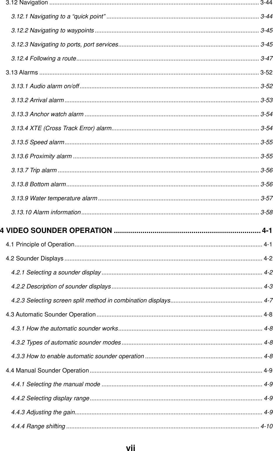
![1. OPERATIONAL OVERVIEW1-31.1.2 Soft keysThe five soft keys’ function changes according to the operation. Their labels fortheir current functions are shown on the screen to the left of the keys. To hide orshow the soft keys press the [SHOW/HIDE] keys.SOFTKEYSDisplay unitWhen you press a soft key one of three operations is executed: the selectedoperation is executed, a sub-set of soft keys appears or a menu is displayed.Some soft keys show their currently selected soft key option in reverse video asbelow.MARKRETURNWPT MKON/OFF+E2 °RV2 nm 359.9° R 11.7nmE1 °RV1 nm 12/ 319.9°R3nm SPHURINGSON/OFFRadar display](https://usermanual.wiki/Furuno-USA/9ZWRTR070.OPERATORS-MANUAL-PART-1/User-Guide-132136-Page-19.png)
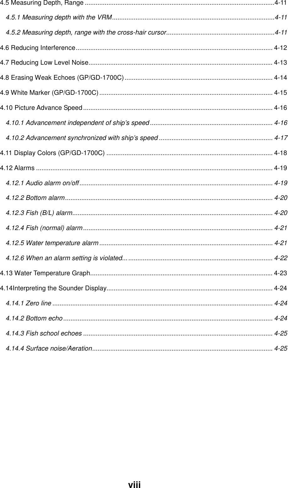
![1. OPERATIONAL OVERVIEW1-41.1.3 [ENTER] knobThe [ENTER] knob functions to register input and enter alphanumeric data suchas waypoint name. Clockwise rotation of the knob selects an alphabet, symbol ornumeric, in one of the sequences shown below. After you have selected desiredcharacter push the [ENTER] knob to register your selection.[ENTER] knob[ENTER] knobAlphabet, symbol, numericA→B→C→D→E→F→G→H→I→J→K→L→M→N→O→P→Q→R→S→T→U→V→W→X→Y→Z→_→’→#→0→1→2→3→4→5→6→7→8→9→A→B…Numerics0→1→2→3→4→5→6→7→8→9→0→1…](https://usermanual.wiki/Furuno-USA/9ZWRTR070.OPERATORS-MANUAL-PART-1/User-Guide-132136-Page-20.png)
![1. OPERATIONAL OVERVIEW1-61.3 Turning the Unit On/OffPress and hold down the [POWER/BRILL] key to turn the unit on. A beep soundsand the equipment proceeds in the sequence shown below, displaying the startupscreen, startup test results and the chart usage disclaimer in that order. Thestartup test checks the ROM, RAM, internal battery and backup data for properoperation, displaying the results for each if there is NG (No Good). If error isfound an appropriate message appears on the screen. For any NG, try to pressany key to go to the chart disclaimer screen.RADAR PLOTTER STATION NAME: FLYBRGFURUNO ELECTRIC CO., LTD.CHARTS AVAILABLEFLYBRDG = ANB01004RADAR = ANB01003LICENSE NO.******** STARTUP TESTROM NGRAM NGBACKUP DATA NGINTERNAL BATTERY NGProduct information Startup test Chart disclaimerIf error is found appropriatemessage appears here.(Only when NG is found.)Startup sequenceYou may press any key at the chart disclaimer screen to show the last-used radardisplay, or wait several seconds to let the equipment do it for you.To turn the unit off, press and hold down the [POWER/BRILL] key. Release thekey when you see the timer which counts down the time remaining until the unit isshut off. To protect the LCD attach the hard cover.Note: The very first time the system is powered the display shows the messagedisplayed below which asks you if you want to start the demonstrationmode. Press the [ENTER] knob to start the demo mode, or press the[CLEAR] key to start normal operation. For further details about thedemonstration mode, see paragraph 1.9. START DEMO MODE?YES ... PUSH 'ENTER' KNOBNO ...PUSH 'CLEAR' KEY(CLEAR KEY TO SKIP DEMO.)](https://usermanual.wiki/Furuno-USA/9ZWRTR070.OPERATORS-MANUAL-PART-1/User-Guide-132136-Page-22.png)
![1. OPERATIONAL OVERVIEW1-71.4 Adjusting Display Brilliance, Panel Brilliance,Contrast, HueYou can adjust display brilliance, panel brilliance, contrast (MODEL-1700 seriesonly) and hue (MODEL-1700C series only) as shown below.1.4.1 Display brilliance, panel brilliance1. Press the [POWER/BRILL] key with a touch-and-release action. A set of soft keys foradjustment of brilliance and contrast or hue appear.BRILLIANCE OF DISPLAY8BRILLCONTSTDISPLYBRILLPANELBRILLCONTSTHUERETURNRADARTXBrilliance adjustment soft keys2. Press the DISPLY BRILL or PANEL BRILL soft key as appropriate. An adjustment windowappears at the bottom of the screen. This window shows the name of the item selectedfor adjustment plus current level, by bar graph.DISPLAY BRILLIANCE8PANEL BRILLIANCE8Display brilliance Panel brillianceDisplay brilliance and panel brilliance windows3. Adjust the [ENTER] knob, clockwise to raise the setting or counterclockwise to decreaseit. You may also use the soft key pressed at step 2, in which case the item selected isadjusted cyclically, from low to high. Eight levels of display brilliance and panel brillianceare available.4. Hit the RETURN soft key to finish.](https://usermanual.wiki/Furuno-USA/9ZWRTR070.OPERATORS-MANUAL-PART-1/User-Guide-132136-Page-23.png)
![1. OPERATIONAL OVERVIEW1-81.4.2 Contrast1. Press the [POWER/BRILL] key with a touch-and-release action.2. Press the CONTST (MODEL-1700 series) or CONTST/HUE (MODEL-1700Cseries) soft key.3. For the MODEL-1700C series, two soft keys appear at the pressing of theCONTST/HUE soft key: CONTST and HUE. Press the CONTST soft key toadjust the contrast.4. Adjust the [ENTER] knob, clockwise to raise the setting or counterclockwise todecrease it. You may also use the soft key pressed at step 2 (3 for theMODEL-1700C series), in which case the item selected is adjusted cyclically,from low to high. 16 levels (MODEL-1700 series) and 10 levels (MODEL-1700C series) of contrast are available.CONTRAST8Contrast window1.4.3 Hue (MODEL-1700C series only)1. Press the [POWER/BRILL] key with a touch-and-release action.2. Press the CONTST/HUE soft key.3. Press the HUE soft key to show the hue setting window.HUE▲ DAYNIGHTTWILIGHTMANUAL SET▼Hue window4. Operate the cursor pad to select hue desired, referring to the table below.MANUAL SET restores default hue setting.Night Day Twilight Applicable modeCharacters Red Black Green Plotter, radar, sounderRadar ring Red Green Green RadarRadar echo Green Yellow Green RadarBackground Black White Blue Plotter, radar, sounderLandmass Light Yellow Yellow Green Radar5. Hit the RETURN soft key to finish.](https://usermanual.wiki/Furuno-USA/9ZWRTR070.OPERATORS-MANUAL-PART-1/User-Guide-132136-Page-24.png)
![1. OPERATIONAL OVERVIEW1-101.5.2 Selecting a display1. Press the [DISP] key to show the full-screen selection window. The icons ofmodes not available are shaded in grey. PAGE 1-PAGE 5 are “hot page”combination screen displays which you may configure as you like. For furtherdetails see paragraph 5.5 Hot Page Setup.PAGE 1 PAGE 2 PAGE 3 PAGE 4 PAGE 5RADAR PLOT SNDR NAV OVRLY· TURN KNOB TO SELECT MODE AND PUSH TO SET.· PUSH ANY SOFTKEY TO SELECT IMAGE SOURCE.Basic displayscreensPreset combinationscreen displaysFull-screen selection window2. Rotate the [ENTER] knob to select a basic display screen or a “hot page”screen. If you selected a “hot page” press the [ENTER] knob to finish.3. If you selected a basic display screen at step 2, push the [ENTER] knob.The corresponding combination screen selection window appears.RADAR PLOT SNDR NAVOVRLYPUSH ENTER KNOB.Combination screen selection window4. Operate the [ENTER] knob to select a combination display and push it to set.](https://usermanual.wiki/Furuno-USA/9ZWRTR070.OPERATORS-MANUAL-PART-1/User-Guide-132136-Page-26.png)
![1. OPERATIONAL OVERVIEW1-121.5.4 Selecting image sourceWhen more than one network radar or a blackbox echo sounder is connected tothe equipment you may select image source for each as shown below. This is notnecessary when only one network radar or echo sounder is connected.1. Press the [DISP] key.2. Press any soft key to show the following display.RADAR SOURCE RADARSOUNDER SOURCE ETRIF THERE IS MORE THANONE NETWORK RADAR ORECHO SOUNDER, YOU MAYSELECT THE IMAGESOURCES FOR DISPLAY.▲SELECTSOURCEEDITRETURNSelect source menu3. Select RADAR SOURCE or SOUNDER SOURCE as appropriate and pressthe EDIT key.RADAR SOURCERADARSOUNDER SOURCESOUNDER Radar source Sounder sourceRadar source and sounder source windows4. Enter host name with the [ENTER] knob.5. Press the RETURN soft key to finish.6. Press the [MENU] key to close the menu.](https://usermanual.wiki/Furuno-USA/9ZWRTR070.OPERATORS-MANUAL-PART-1/User-Guide-132136-Page-28.png)
![1. OPERATIONAL OVERVIEW1-131.6 Entering the MOB Mark, Setting MOB asDestinationThe MOB (Man Overboard) mark functions to mark man overboard position. Youcan inscribe this mark from any mode, except while playing back data orconducting a test. Note that this function requires position data.Manoverboad Range, bearingCurrentpositionMOBmarkBearing and range to MOB positionM(MOB)MOB concept1. Press and hold down the [SAVE/MOB] key. The display shows the waypointnumber being saved (youngest empty waypoint number, 001-999) followed bythe MOB confirmation window.MAN OVER BOARD!GO TO (MOB)? YES ... PUSH ENTER KNOB NO : PUSH CLEAR KEY WAYPOINT SAVED! XXXWPT CONTINUE PUSHING FOR MOB!After 3seconds|XXX = Waypoint numberMOB mark messages2. Push the [ENTER] knob to select MOB position as destination, or press the[CLEAR] key to only mark position as a waypoint. If you select the MOBposition as destination;• A full-screen radar, plotter or overlay (color model only) appears dependingon the display in use.• The MOB mark “M” appears at the MOB position and a line runs between itand current position. This line shows the shortest course to the MOBposition.• Range and bearing to the MOB position are shown in a data box.MOB162.5° 0.49 nmRange to MOB positionBearing to MOB positionMOB data boxTo erase an MOB mark, place the cursor on the MOB mark and press the[CLEAR] key followed by the [ENTER] knob to erase the waypoint.](https://usermanual.wiki/Furuno-USA/9ZWRTR070.OPERATORS-MANUAL-PART-1/User-Guide-132136-Page-29.png)
![1. OPERATIONAL OVERVIEW1-141.7 Data BoxesData boxes, providing navigation data, may be shown at the bottom of any full-screen display. Up to six data boxes (two in case of large characters) may beshown. The user may choose which data to display, where to locate it, and showor hide it as desired. Further, data boxes may be set independently for eachdisplay mode (radar, plotter, sounder). For how to select data for the data boxes,see paragraph 5.4 Data Box Setup.17.0 R8.2nm E1V1E2 320.1 R 359.9 R11.7nmV2 10.9nm12/3nmSPHU319. 9RTRAIL 30m02m30sG1 ING2 OUTES 2IR LNRRNG123.5 nmSPEED27.6kt TRIP LOG1022.5nmDEPTH276ft Data boxesRadar display, showing data boxes1.7.1 Showing, hiding data boxes with soft keyRadar: ZOOM/D.BOX → D. BOX ON, D.BOX OFFPlotter: D.BOX ON, D.BOX OFFSounder: MODE/D.BOX → D.BOX ON, D.BOX OFF1.7.2 Rearranging data boxesYou may select the location for data boxes as follows:1. Use the cursor pad to place the cursor in the data box you want to move andpress the [ENTER] knob.2. Use the cursor pad to drag the data box to the location desired and press the[ENTER] knob.1.7.3 Temporarily erasing a data boxIf a data box is obscuring a desired object you may temporarily erase the box.Use the cursor pad to place the cursor inside the data box you wish to erase andpress the [CLEAR] key. To redisplay the box, press the D.BOX soft key twice.](https://usermanual.wiki/Furuno-USA/9ZWRTR070.OPERATORS-MANUAL-PART-1/User-Guide-132136-Page-30.png)
![1. OPERATIONAL OVERVIEW1-151.8 Soft KeysThe soft keys provide for one-touch call up of a desired function. The default softkey settings for the radar display areSoft key #1: Heading line on/offSoft key #2: Range ring on/offSoft key #3: Suppressing sea clutterSoft key #4: Echo trail on/offSoft key #5: Outputting TLL data1.8.1 Executing a function1. Press the [HIDE/SHOW] key to show the soft key labels for functions.+E2 °RV2 nm 359.9° R 11.7nmHLRNGSEATRLTLL12/ 319.9°R3nm SPHUE1 °RV1 nm Sample functionkeysPlotter display, showing soft keys2. Press soft key desired.3. For or example, heading line on/off, press the soft key to erase the headingline.4. Release the soft key to finish.Note: Soft keys can be programmed for the radar, plotter and sounder displays.For further details see the following:Plotter: paragraph 5.2.2Radar: paragraph 5.8.3Sounder: paragraph 5.9.4](https://usermanual.wiki/Furuno-USA/9ZWRTR070.OPERATORS-MANUAL-PART-1/User-Guide-132136-Page-31.png)
![1. OPERATIONAL OVERVIEW1-161.9 Demonstration DisplayThe demonstration display provides simulated operation of the equipment to helpacquaint you with the many features it has to offer. It allows you to view andcontrol a simulated radar, plotter and sounder picture, without GPS equipment,radar input or blackbox sounder. All controls are operative, thus you may practicesetting guard zone, EBL/VRM, etc.To start the demonstration display;1. Press the [MENU] key.2. Press the SYSTEM CONFIGURATION, SYSTEM SETUP and SIMULATIONsoft keys.RADAR SIMULATION MODE 1PLOTTERSIMULATION MODESOUNDERSIMULATION MODESIMULATION SPEED0.0ktSIMULATION COURSE000.0˚SIMULATION LAT45˚37.000'NSIMULATION LON122˚30.000'WSIMULATION START TIME000:00 01.JAN.00RADAR SIMULATION DATANO▲SIMSETUPEDITRETURNSimulation mode setup menu3. Select RADAR, PLOTTER or SOUNDER as appropriate and press the EDITsoft key.PLOTTER▲ SIMULATION MODELIVE▼RADAR▲ SIMULATION MODE 1SIMULATION MODE 2LIVE▼SOUNDER▲ SIMULATION MODELIVE▼Plotter Radar SounderPlotter, radar, sounder simulation mode selection windows](https://usermanual.wiki/Furuno-USA/9ZWRTR070.OPERATORS-MANUAL-PART-1/User-Guide-132136-Page-32.png)
![1. OPERATIONAL OVERVIEW1-174. Use the cursor pad to select simulation mode desired and press the RETURNsoft key.SIMULATION MODE (Plotter, sounder): Turns simulation mode on.SIMULATION MODE 1 (Radar): Uses standard demonstration display.SIMULATION MODE 2 (Radar): Uses data read into the unit from a network radar.LIVE: Turns simulation mode off.5. Select SIMULATION SPEED and press the EDIT soft key.6. Enter speed (setting range, 0-99 kt, default speed, 10 kt) with the [ENTER]knob and press the RETURN soft key.7. Select SIMULATED LAT and press the EDIT soft key.8. Enter latitude (setting range, 85°N-85°S, default setting, 45°37’N) and pressthe RETURN soft key.9. Select SIMULATED LON and press the EDIT soft key.10. Enter longitude (setting range, 180°E-180°W, default setting, same as GPSdefault setting) and press the RETURN soft key.11. Select SIMULATION START TIME and press the EDIT soft key.12. Enter start date and time (default date and time: 2001/1/1, 0:0) and press theRETURN soft key.13. If you selected SIMULATION MODE 2 at step 4, select YES and press theRETURN soft key. Press the [ENTER] knob to erase simulation data and getnew data. The message “Now getting demo data. Do not cut off display unit.”appears while the unit is receiving radar data. If the network radar could not be found “Radar source is not found. Cannot getdemo data.” appears. And if the radar is not active, the message “Radar is notactive. Cannot get demo data.” is displayed.](https://usermanual.wiki/Furuno-USA/9ZWRTR070.OPERATORS-MANUAL-PART-1/User-Guide-132136-Page-33.png)