Furuno USA 9ZWRTR078 MARINE RADAR User Manual OPERATORS MANUAL
Furuno USA Inc MARINE RADAR OPERATORS MANUAL
UserManual.wiki
>
Furuno USA
>
9ZWRTR078 User Manual
OPERATORS MANUAL
Navigation menu
Upload a User Manual
Namespaces
Wiki Guide
HTML
PDF
Info
Views
User Manual
Discussion / Help
Navigation
![1-11. RADAR OPERATION 1.1 Turning on the Power The [POWER] switch is located at the left corner of the control unit. Open the power switch cover and press the switch to turn on the radar system. To turn off the radar, press the switch again. The screen shows the bearing scale and digital timer approximately 15 seconds after power-on. The timer counts down three minutes of warm-up time. During this period the magnetron (transmitter tube) is warmed for transmission. When the timer has reached 0:00, the indication “ST-BY” appears at the screen center, meaning the radar is now ready to transmit pulses. In stand-by condition, markers, rings, map, charts, etc. are not shown. Further, ARPA is cancelled and the AIS display is erased. In warm-up and stand-by condition, you will see the message BRG SIG MISSING because the antenna is not rotating; azimuth signal is not being sent to the processor unit. ON TIME and TX TIME counts in hours and tenths of hour appear at the screen center. 1.2 Transmitter ON After the power is turned on and the magnetron has warmed up, ST-BY appears at the screen center, meaning the radar is ready to transmit radar pulses. You may transmit by pressing the [STBY/TX] key on the full keyboard or roll the trackball to choose the TX STBY box at the bottom left corner of the display and then pushing the left button (above the trackball). The left-hand side of the guidance box at the bottom right corner of the screen changes from TX to STBY. GuidanceboxSTBY/TXSTBYTX STBY box Radar display](https://usermanual.wiki/Furuno-USA/9ZWRTR078/User-Guide-356443-Page-19.png)
![1. RADAR OPERATION 1-2 The radar is initially set to previously used range and pulse length. Other settings such as brilliance levels, VRMs, EBLs and menu option selections are also set to previous settings. The [STBY/TX] key (or TX STBY box) toggles the radar between STBY and TRANSMIT status. The antenna stops in stand-by and rotates in transmit. The magnetron ages with time resulting in a reduction of output power. It is highly recommended that the radar be set to stand-by when not used for an extended period of time. Quick start Provided that the radar was once in use with the transmitter tube (magnetron) still warm, you can turn the radar into TRANSMIT condition without three minutes of warm-up. If the [POWER] switch has been turned off by mistake or the like and you wish to restart the radar promptly, turn on the [POWER] switch not later than 10 seconds after power-off.](https://usermanual.wiki/Furuno-USA/9ZWRTR078/User-Guide-356443-Page-20.png)
![1. RADAR OPERATION 1-5 [MARK MENU] 1 BACK 2 OWN SHIP MARK OFF/ON 3 STERN MARK OFF/ON 4 INDEX LINE BEARING REL/TRUE 5 INDEX LINE 1/2/3/6 6 INDEX LINE MODE VERTICAL/HORIZONTAL 7 8 EBL OFFSET BASE POINT STAB GND/STAB HDG/ STAB NORTH 9 EBL CURSOR BEARING REL/TRUE 0 RING OFF/ON1.4 Main Menu You may access the MAIN menu from the full keyboard or by using the trackball. In later sections only the procedure for menu operation by trackball is given. Main menu operation by keyboard 1. Press the [MENU] key. The MAIN menu appears in the text area at the right side of the screen. [MAIN MENU] 1 [ECHO] 2 [MARK] 3 [ALARM] 4 [ARPA AIS] 5 [PLOTTER] 6 [CARD] 7 [NAV DATA] 8 [NAV LINE WPT] 9 [CUSTOMIZE TEST] Echo processing functionsMainly turns markers on/off.Sets guard alarm functions; outputs alarm signal.Sets ARPA and AIS functions.Chart and track functionsMemory card functionsTurns nav data on/off.Processes nav lines and waypoints.Customizes operation; executes diagnostics. MAIN menu 2. Press the numeral key corresponding to the menu you wish to open. For example, press the [2] key to open MARK menu. MARK menu 3. Press the numeral key corresponding to the item you wish to set. 4. Consecutively press the same numeral key pressed at step 3 to choose appropriate option and then press the [ENTER MARK] key to register your selection. 5. Press the [MENU] key to close the menu. To clear a line of numeric data:Use the [CANCEL TRAILS] key.Switch between plus and minus,North and South or East and West:Use the [2] key.Useful keys in menu operation](https://usermanual.wiki/Furuno-USA/9ZWRTR078/User-Guide-356443-Page-23.png)
![1. RADAR OPERATION 1-6 [MARK MENU] 1 BACK 2 OWN SHIP MARK OFF/ON 3 STERN MARK OFF/ON 4 INDEX LINE BEARING REL/TRUE 5 INDEX LINE 1/2/3/6 6 INDEX LINE MODE VERTICAL/HORIZONTAL 7 8 EBL OFFSET BASE POINT STAB GND/STAB HDG/ STAB NORTH 9 EBL CURSOR BEARING REL/TRUE 0 RING OFF/ONMain menu operation by trackball 1. Roll the trackball to choose the MENU box at the right side of the screen. The guidance box at the bottom right corner (see the illustration at the bottom of the next page for location) now reads “DISP MAIN MENU.” MENU Menu box 2. Push the left button to display the MAIN menu. [MAIN MENU] 1 [ECHO] 2 [MARK] 3 [ALARM] 4 [ARPA AIS] 5 [PLOTTER] 6 [CARD] 7 [NAV DATA] 8 [NAV LINE WPT] 9 [CUSTOMIZE TEST] Echo processing functionsMainly turns markers on/off.Sets guard alarm functions; outputs alarm signal.Sets ARPA and AIS functions.Chart and track functionsMemory card functionsTurns nav data on/off.Processes nav lines and waypoints.Customizes operation; executes diagnostics. MAIN menu 3. Roll the wheel to choose the menu you wish to open and then push the wheel or the left button. For example, choose the 2 [MARK] menu and then push the wheel or the left button. MARK menu 4. Roll the wheel to choose item desired and then push the wheel or the left button. 5. Roll the wheel to choose option desired and then push the wheel or the left button to register your selection. 6. Push the right button to close the menu. (Several pushes may be necessary depending on the menu used.)](https://usermanual.wiki/Furuno-USA/9ZWRTR078/User-Guide-356443-Page-24.png)
![1. RADAR OPERATION 1-9 [MARK MENU] 1 ORIGIN MARK STAB GND/SEA 2 ORIGIN MARK(No.)/ ORIGIN MARK(SYMBOL)/ MAP MARK/ WP 1~50/ WP 51~100/ WP 101~150/ WP 151~200/ OWN SHIP SHAPE 9 MAP DISPLAY OFF/ON 0 MAP MARK COLOR* RED/GRN/BLU/YEL/ CYA/MAG/WHT 3. The pop-up menu attached to the MARK box is the MARK menu. To open the menu, push the right button. The menu opens in the text area at the right side of the screen. MARK menu Note: Any menu may be operated from the full keyboard or the trackball, or a combination of the two in case of Control Unit RCU-014. Note that in later sections only the procedure for menu operation by the trackball is given. 4. Roll the wheel to choose item desired and then push the wheel or the left button. Selected item is initially shown in reverse video and changes to normal video and circumscribed when the wheel or the left button is pushed. 5. Roll the wheel to choose option desired and then push the wheel or the left button. Selected option is initially shown in reverse video and changes to normal video and circumscribed when the wheel or the left button is pushed. 6. Push the right button to close the menu. (On some menus several presses of the right button are required to close the menu.) * Not available on IMO radar.](https://usermanual.wiki/Furuno-USA/9ZWRTR078/User-Guide-356443-Page-27.png)
![1. RADAR OPERATION 1-10 [CURSOR MENU] 2 ↓ TARGET DATA & ACQ/TARGET CANCEL/ ACQ/ REF MARK/ EBL OFFSET/ ZOOM/ MARK DELETE/ CHART ALIGN 1.6 Cursor Menu Functions which require the use of the cursor, such as EBL offset and zoom, may be activated directly from the guidance box or from the CURSOR menu, either method with the cursor inside the effective display area. Below is the procedure for choosing a cursor-related function from the CURSOR menu. In later sections only the procedure for selection from the guidance box is given. 1. Roll the trackball to place the cursor inside the effective display area. 2. Roll the wheel to show “TARGET DATA & ACQ / CURSOR MENU” in the guidance box. 3. Push the right button to show the CURSOR menu. CURSOR menu 4. Roll the wheel to choose 2 MARK KID and then push the wheel or the left button. 5. Roll the wheel to choose function desired and then push the wheel or the left button. Note: For operation from the keyboard, you may press the [2] key to choose a function in top-to-bottom order or the [8] key to choose in reverse order. Cursor Menu item Description TARGET DATA & ACQ ARPA: Acquires ARPA target; displays data for chosen ARPA target. AIS: Activates sleeping AIS target; display data for chosen AIS target. TARGET CANCEL ARPA: Cancels tracking on chosen ARPA target. AIS: Sleeps chosen AIS target. ACQ ARPA: Acquires chosen echo. AIS: Activates chosen AIS target. REF MARK Inscribes reference mark, for target-based speed input. EBL OFFSET Offsets EBL, to measure range and bearing between two targets. OFF CENTER Shifts screen center to chosen location. ZOOM Zooms chosen location. MARK DELETE Deletes chosen mark (plotter mark, origin mark or waypoint mark). CHART ALIGN Aligns chart with radar picture.](https://usermanual.wiki/Furuno-USA/9ZWRTR078/User-Guide-356443-Page-28.png)
![1. RADAR OPERATION 1-116. Push the right button to close the menu. The guidance box shows “XX / EXIT.” (XX = function chosen) 7. Roll the trackball to place the cursor where desired. 8. Push the left button to execute the function selected at step 5. 9. To quit the function selected, push the right button when the guidance box shows “XX / EXIT.” (XX = function chosen at step 5) 1.7 Monitor Brilliance The brilliance of the entire screen should be adjusted according to lighting conditions. Monitor brilliance should be adjusted before adjusting relative brilliance levels on the BRILL menu to be explained later. Note: The brilliance of a PC monitor cannot be adjusted from the radar. See the owner’s manual of the PC monitor for how to adjust its brilliance. By keyboard Operate the [BRILL] control on the control unit to adjust brilliance. Turn it clockwise to increase brilliance; counterclockwise to decrease brilliance. Watch the BRILL box (see illustration below) to know current brilliance level. By trackball 1. Roll the trackball to place the arrow on the brilliance level bar in the BRILL box at the bottom left corner of the screen. BRILL1 Place arrow inside boxto adjust screen brilliance.Brilliance barShows brilliance level.26Brilliance levelBrillance, color set no.(For details, see para. 1.50.) BRILL box 2. Roll the wheel downward to increase brilliance or roll it upward to decrease brilliance. The length of the brilliance bar increases or decreases with operation of the wheel. Note: If nothing appears on the screen at power-up when using the mini keyboard (Control Unit RCU-015) or when the radar is in stand-by, press and hold down any key except the power switch for four seconds to automatically set up for medium display brilliance.](https://usermanual.wiki/Furuno-USA/9ZWRTR078/User-Guide-356443-Page-29.png)
![1. RADAR OPERATION 1-15 [ECHO MENU] 1 BACK 2 2ND ECHO REJ OFF/ON 3 TUNE INITIALIZE 4 PM OFF/ON 5 SART OFF/ON 6 WIPER OFF/1/2 1.10 Tuning the Receiver 1.10.1 Choosing the tuning method The tuning method can be selected with the TUNE box at the top of the screen. 1. Roll the trackball to choose the TUNE box (TUNE AUTO or TUNE MAN) at the top of the screen. TUNE AUTO Place arrow inside boxto adjust tuning, whenTUNE MANU is selected.Tuning method (AUTO or MANU)Tuning bar0Tuning level (0 in AUTO TUNE,actual value in MANU TUNE) TUNE box 2. Push the left button or roll the wheel to display TUNE AUTO or TUNE MAN as appropriate. 3. If you used the wheel to choose tuning method, push the wheel or the left button to change setting. 1.10.2 Initializing tuning Automatic tuning is initialized during the installation. However, if you feel that automatic tuning is not working properly try re-initializing it as follows: 1. Roll the trackball to choose the MENU box at the right side of the screen and then push the wheel or the left button. 2. Roll the wheel to choose 1 ECHO and then push the wheel. ECHO menu 3. Roll the wheel to choose 3 TUNE INITIALIZE. 4. Push the wheel or the left button to initialize automatic tuning. (For operation from the keyboard, press the [ENTER MARK] key.) 5. Push the right button twice to close the menu.](https://usermanual.wiki/Furuno-USA/9ZWRTR078/User-Guide-356443-Page-33.png)
![1. RADAR OPERATION 1-17 [HDG MENU] 1 HDG SOURCE AD-10/SERIAL 2 GC-10 SETTING 000.0° 1.11 Aligning Gyrocompass With connection of a gyrocompass, ship's heading is displayed at the right side of the screen. Upon turning on the radar, align the on-screen GYRO readout with the gyrocompass reading by following the procedure shown below. Once you have set the initial heading correctly, resetting is not usually required. However, if the GYRO readout looks wrong or the gyro alarm sounds, follow the procedure below. 1. Roll the trackball to place the arrow in the HDG box at the top right corner of the screen. 2. Push the right button to open the HDG menu. HDG menu 3. Roll the wheel downward to choose GC-10 SETTING and then push the wheel or the left button. The cursor shifts to the far left-hand digit (hundreds place). Note: If heading source selected is not suitable change it at 1 HDG SOURCE to match your heading source. 4. Roll the wheel to set the heading. (For entry through the keyboard use the numeric keys.) 5. Push the wheel to finish. 6. Push the right button to close the menu.](https://usermanual.wiki/Furuno-USA/9ZWRTR078/User-Guide-356443-Page-35.png)
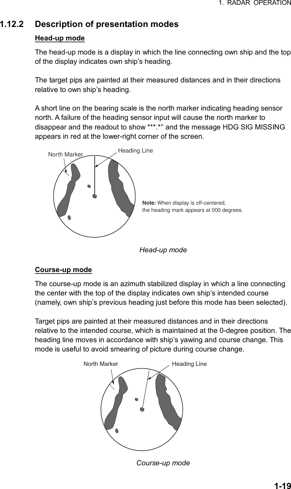
![1. RADAR OPERATION 1-18 1.12 Presentation Modes This radar has the following presentation modes: Relative Motion (RM) Head-up: Unstabilized Head-up TB: Head-up with compass-stabilized bearing scale (True Bearing) where the bearing scale rotates with the compass reading. Course-up: Compass-stabilized relative to ship’s orientation at the time of selecting course-up. North-up: Compass-stabilized with reference to north True Motion (TM) North-up: Ground or sea stabilized with compass and speed inputs 1.12.1 Choosing presentation mode By keyboard Press the [MODE] key consecutively to choose presentation mode desired. The PRESENTATION MODE box shows the current presentation mode. (See the illustration below.) By trackball 1. Roll the trackball to place the arrow in the PRESENTATION MODE box at the top left corner of the screen. HEAD UP RM** = Other modes:HEAD UP TB RM, COURSE UP RM,NORTH UP RM, NORTH UP TM PRESENTATION MODE box 2. Push the left button to choose mode desired. Loss of gyrocompass signal When the compass signal is lost, “HEADING SET” appears in red at the gyro readout, the presentation mode automatically becomes head-up, all ARPA and AIS targets and map or chart are erased. After restoring the compass signal, choose the presentation mode with the [MODE] key or the PRESENTATION MODE box.](https://usermanual.wiki/Furuno-USA/9ZWRTR078/User-Guide-356443-Page-36.png)
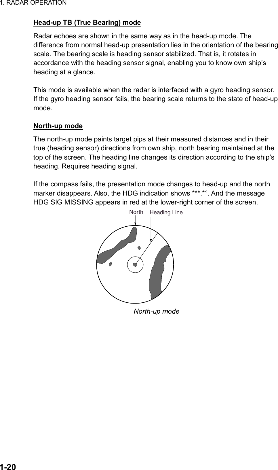
![1. RADAR OPERATION 1-21True motion mode Own ship and other moving objects move in accordance with their true courses and speed. In ground stabilized TM, all fixed targets, such as landmasses, appear as stationary echoes. In the sea stabilized TM without set and drift inputs, the landmass can move on the screen. Note that true motion is not available on the 72 nm or 96 nm range scale. When own ship reaches a point corresponding to 75% of the radius of the display, own ship position is automatically reset to a point of 75% radius opposite to the extension of the heading line passing through the display center. You may also reset the own ship marker manually by pressing the [CU/TM RESET] key, or roll the trackball to choose the CU/TM RESET box at the bottom right corner of the display and then push the left button. If the heading sensor fails, the mode is changed to the head-up and the north marker disappears. The HDG readout shows ***.*° and the message HDG SIG MISSING appears in red at the lower-right corner of the screen. Heading LineNorth True motion mode Automatic resetting of own ship mark in true motion mode 000 010 020030040050060070080090100110120130140150160170180190200210220230240250260270280290300310320330340 350 000 010 020030040050060070080090100110120130140150160170180190200210220230240250260270280290300310320330340 350HeadinglineNorthmarker000 010 020030040050060070080090100110120130140150160170180190200210220230240250260270280290300310320330340 350(a) True motionis selected(b) Own ship has reached apoint 75% of display radius(c) Own ship is automaticallyreset to 75% of radius](https://usermanual.wiki/Furuno-USA/9ZWRTR078/User-Guide-356443-Page-39.png)
![1. RADAR OPERATION 1-22 [SPEED MENU] 1 SHIP SPEED LOG(BT)/LOG(WT)/ GPS/MANUAL/REF 2 MANUAL SPEED 00.0kt 3 SET/DRIFT OFF/ON 1.13 Entering Own Ship's Speed The ARPA and azimuth stabilized presentation modes require own ship speed input and compass signal. The speed can be entered from a log (STW) or GPS (SOG) or manually on the menu. 1.13.1 Automatic speed input by log or GPS navigator 1. Roll the trackball to place the arrow in the SPD box at the top right corner of the screen. 2. Push the right button to display the SPEED menu. SPEED menu 3. Roll the wheel to choose 1 SHIP SPEED and then push the wheel or the left button. 4. Roll the wheel to choose the appropriate source for automatic speed input and then push the wheel or the left button. LOG (BT): Log, speed over ground (SOG). Note that a log cannot produce BT (Bottom Tracking) speed in deep waters. LOG (WT): Log, speed thru water (STW) GPS: Speed input by GPS navigator 5. Push the right button to close the menu. LOG appears at the right side of the screen. Notes on speed input • IMO Resolution A.823(19) for ARPA recommends that a speed log to be interfaced with an ARPA should be capable of providing through-the-water speed data (forward speed). • Be sure not to choose a LOG option when a speed log is not connected. If the log signal is not provided, the ship speed readout at the top of the screen will be blank. In the event of a log error, enter speed manually. • SPD **.* and LOG appear if no log signal is present for 30 s while the ship’s speed has been more than 5 kt. • With the serial speed inputs and SOG selection, if the type of data is changed from SOG to STW the label SOG appears in red (at the upper right corner of the display).](https://usermanual.wiki/Furuno-USA/9ZWRTR078/User-Guide-356443-Page-40.png)
![1. RADAR OPERATION 1-24 1.14 Choosing the Range Scale The selected range scale, range ring interval and pulselength are shown at the upper left corner on the screen. When a target of interest comes closer, reduce the range scale so that it appears in 50-90% of the display radius. By keyboard Use the [RANGE] key to choose range desired. Hit the “+” part of the key to raise the range; the “-“ part to lower the range. By trackball 1. Roll the trackball to choose the RANGE box at the top left corner of the screen. The guidance box shows “RANGE DOWN / RANGE UP.” 0.125NM0.025 RANGE box 2. Push the left button to lower the range; the right button to raise the range. You may also choose the range by rolling the wheel and then pushing it or the left button.](https://usermanual.wiki/Furuno-USA/9ZWRTR078/User-Guide-356443-Page-42.png)
![1. RADAR OPERATION 1-25 [PICTURE MENU] 1 INT REJECT OFF/1/2/3 2 ECHO STRETCH OFF/1/2/3 3 ECHO AVERAGE OFF/1/2/3 4 NOISE REJ OFF/ON 5 AUTO STC OFF/ON 6 AUTO RAIN OFF/ON 7 VIDEO CONTRAST A/B/C/D 8 [PULSE] 9 [CONDITION] 0 DEFAULT 1.15 Choosing the Pulselength The pulselength in use is displayed at the upper-left position of the screen using the indications shown in the table below. Label and pulselength Indication Pulselength (µs)S (Short pulse) — S1 (Short pulse 1) 0.07 S2 (Short pulse 2) 0.15 M1 (Medium pulse 1) 0.3 M2 (Medium pulse 2) 0.5 M3 (Medium pulse 3) 0.7 L (Long pulse) 1.2 Appropriate pulselengths are preset to individual range scales and function keys. If you are not satisfied with the current pulselength settings, you may change them as shown below. 1.15.1 Choosing pulselength You can choose the pulselength for the 0.5 to 24 nm range scales as below. 1. Roll the trackball to choose the PICTURE box at the right side of the screen. Note: The PICTURE box sets up the radar picture according to expected usage, such as harbor navigation, long range, short range, etc. For further details see paragraph 1.33. 2. Push the right button to show the PICTURE menu. PICTURE menu](https://usermanual.wiki/Furuno-USA/9ZWRTR078/User-Guide-356443-Page-43.png)
![1. RADAR OPERATION 1-26 [PULSE MENU] 1 BACK 2 0.5NM S1/S2 3 0.75NM S1/S2/M1 4 1.5NM S1/S2/M1 5 3NM S2/M1/M2/M3 6 6NM M1/M2/M3/L 7 12-24NM M2/M3/L 3. Roll the wheel to choose 8 [PULSE] and then push the wheel. PULSE menu 4. Roll the wheel to choose a range and then push the wheel or the left button. 5. Roll the wheel to choose pulselength desired and then push the wheel or the left button. 6. Push the right button twice to close the menu. 1.15.2 Choosing pulselength 1. Roll the trackball to choose the PULSELENGTH box at the left side of the screen. The guidance box shows “PULSE NARROW / PULSE WIDE.” PULSE XX** XX = Pulse width setting PULSELENGTH box 2. Push the left button to shorten the pulselength or the right button to widen the pulselength. You may also choose the pulselength by rolling the wheel and pushing it or the left button.](https://usermanual.wiki/Furuno-USA/9ZWRTR078/User-Guide-356443-Page-44.png)
![1. RADAR OPERATION 1-271.16 Adjusting the Sensitivity The gain control adjusts the sensitivity of the receiver. The proper setting is such that the background noise is just visible on the screen. If you set up for too little sensitivity, weak echoes may be missed. On the other hand excessive sensitivity yields too much background noise; strong targets may be missed because of the poor contrast between desired echoes and the background noise on the display. To adjust receiver sensitivity, adjust the gain control so background noise is just visible on the screen. By keyboard While monitoring the gain level bar at the top of the screen, operate the [GAIN] control to adjust the sensitivity. By trackball 1. Roll the trackball to place the arrow on the gain level bar at the top of the screen. GAIN Place arrow insidewindow to adjust gain.Level bar30 GAIN box 2. Roll the wheel downward to increase the gain or upward to decrease it.](https://usermanual.wiki/Furuno-USA/9ZWRTR078/User-Guide-356443-Page-45.png)
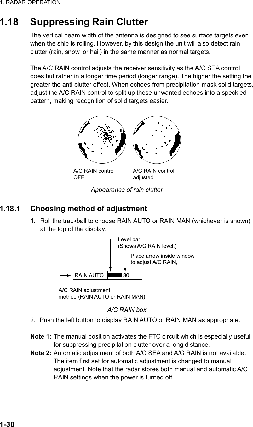
![1. RADAR OPERATION 1-28 1.17 Suppressing Sea Clutter Echoes from waves cover the central part of the display with random signals known as sea clutter. The higher the waves, and the higher the antenna above the water, the further the clutter will extend. When sea clutter masks the picture, suppress it by the A/C SEA control, either manually or automatically. 1.17.1 Choosing method of adjustment 1. Roll the trackball to choose SEA AUTO or SEA MAN (whichever is shown) at the top of the display. SEA AUTO Place arrow inside windowto adjust A/C SEA.A/C SEA adjustmentmethod (SEA AUTO or SEA MAN)Level bar30 A/C SEA box 2. Push the left button to display SEA AUTO or SEA MAN as appropriate. Note: Automatic adjustment of both A/C SEA and A/C RAIN is not available. The item first set for automatic adjustment is changed to manual adjustment. Note that the radar stores both manual and automatic A/C SEA settings when the power is turned off. 1.17.2 Automatic adjustment by the A/C SEA control Sea clutter, as well as rain clutter, can be automatically adjusted with the A/C SEA control. Note: The auto A/C function can erase weak target echoes. Adjust the control carefully, watching the display. By keyboard 1. Choose SEA AUTO following the procedure in paragraph 1.17.1. 2. While observing the A/C SEA level bar, adjust the A/C SEA with the [A/C SEA] control. 15 levels are available. By trackball 1. Choose SEA AUTO following the procedure in paragraph 1.17.1. 2. Roll the trackball to place the arrow in the A/C SEA level bar at the top of the display. 3. While observing the A/C SEA level bar, roll the wheel downward to increase the A/C SEA or upward to decrease it. 15 levels are available.](https://usermanual.wiki/Furuno-USA/9ZWRTR078/User-Guide-356443-Page-46.png)
![1. RADAR OPERATION 1-291.17.3 Manual adjustment of A/C SEA The A/C SEA control reduces the amplification of echoes at short ranges (where clutter is the greatest) and progressively increases amplification as the range increases, so amplification will be normal at those ranges where there is no sea clutter. The proper setting of the A/C SEA should be such that the clutter is broken up into small dots, and small targets become distinguishable. If the setting is set too low, targets will be hidden in the clutter, while if the setting is too high, both sea clutter and targets will disappear from the display. In most cases adjust the control until clutter has disappeared to leeward, but a little is still visible windward. A/C SEA adjusted;sea clutter suppressedSea clutter atscreen center By keyboard 1. Choose SEA MAN following the procedure in paragraph 1.17.1. 2. Watching the A/C SEA level bar at the top of the display, adjust the A/C SEA with the [A/C SEA] control By trackball 1. Choose SEA MAN following the procedure in paragraph 1.17.1. 2. Roll the trackball to place the arrow on the A/C SEA level bar at the top of the display. 3. While observing the A/C SEA level bar, roll the wheel downward to increase the A/C SEA or upward to decrease it. 255 levels are available.](https://usermanual.wiki/Furuno-USA/9ZWRTR078/User-Guide-356443-Page-47.png)
![1. RADAR OPERATION 1-311.18.2 Automatic adjustment of A/C RAIN By keyboard 1. Choose RAIN AUTO following the procedure in paragraph 1.17.1. 2. Adjust the A/C RAIN with the [A/C RAIN] control. 15 levels are available. By trackball 1. Choose RAIN AUTO following the procedure in paragraph 1.17.1. 2. Roll the trackball to place the arrow in the A/C RAIN level bar at the top of the display. 3. While observing the A/C RAIN level bar, roll the wheel downward to increase the A/C RAIN or upward to decrease it. 15 levels are available. 1.18.3 Manual adjustment of A/C RAIN By keyboard 1. Choose RAIN MAN following the procedure in paragraph 1.17.1. 2. Watching the A/C RAIN level bar at the top of the display, adjust the A/C RAIN with the [A/C RAIN] control. Four levels are available. By trackball 1. Choose RAIN MAN following the procedure in paragraph 1.17.1. 2. Roll the trackball to place the arrow on the A/C RAIN level bar at the top of the display. 3. Watching the A/C RAIN level bar at the top of the display, roll the wheel downward to increase the A/C RAIN or upward to decrease it. Four levels are available.](https://usermanual.wiki/Furuno-USA/9ZWRTR078/User-Guide-356443-Page-49.png)
![1. RADAR OPERATION 1-32 [PICTURE MENU] 1 INT REJECT OFF/1/2/3 2 ECHO STRETCH OFF/1/2/3 3 ECHO AVERAGE OFF/1/2/3 4 NOISE REJ OFF/ON 5 AUTO STC OFF/ON 6 AUTO RAIN OFF/ON 7 VIDEO CONTRAST A/B/C/D 8 [PULSE] 9 [CONDITION] 0 DEFAULT 1.19 Interference Rejector Mutual radar interference may occur in the vicinity of another shipborne radar operating in the same frequency band (9 GHz). It is seen on the screen as a number of bright spikes either in irregular patterns or in the form of usually curved spoke-like dotted lines extending from the center to the edge of the picture. Activating the interference rejector circuit can reduce this type of interference. The interference rejector is a kind of signal correlation circuit. It compares the received signals over successive transmissions and suppresses randomly occurring signals. There are three levels of interference rejection depending on the number of transmissions that are correlated. Interference 1. Roll the trackball to choose the PICTURE box at the right side of the screen. 2. Push the right button to show the PICTURE menu. PICTURE menu](https://usermanual.wiki/Furuno-USA/9ZWRTR078/User-Guide-356443-Page-50.png)
![1. RADAR OPERATION 1-34 [MARK MENU] 1 BACK 2 OWN SHIP MARK OFF/ON 3 STERN MARK OFF/ON 4 INDEX LINE BEARING REL/TRUE 5 INDEX LINE 1/2/3/6 6 INDEX LINE MODE VERTICAL/HORIZONTAL 7 8 EBL OFFSET BASE POINT STAB GND/STAB HDG/ STAB NORTH 9 EBL CURSOR BEARING REL/TRUE 0 RING OFF/ON 1.20 Measuring the Range The range to a target may be measured three ways: with the fixed range rings, with the cursor, or with the VRM. Use the fixed range rings to obtain a rough estimate of the range to a target. They are the concentric solid circles about own ship, or the sweep origin. The number of rings is automatically determined by the selected range scale and their interval is displayed at the upper-left position of the screen. Count the number of rings between the center of the display and the target. Check the range ring interval and judge the distance of the echo from the inner edge of the nearest ring. 1.20.1 Turning range rings on/off 1. Roll the trackball to choose the MENU box at the right side of the screen. The guidance box at the bottom right corner (see the illustration at the bottom of the next page for location) now reads “DISP MAIN MENU.” 2. Push the left button to display the MAIN menu. 3. Roll the wheel to choose 2 [MARK] and then push the wheel or the left button. MARK menu 4. Roll the wheel to choose 0 RING and then push the wheel or the left button. 5. Roll the wheel to choose OFF or ON as appropriate and then push the wheel or the left button. 6. Push the right button twice to close the menu.](https://usermanual.wiki/Furuno-USA/9ZWRTR078/User-Guide-356443-Page-52.png)
![1. RADAR OPERATION 1-351.20.2 Measuring range by the variable range marker (VRM) There are two VRMs, No. 1 and No. 2, which appear as dashed rings so that you can discriminate them from the fixed range rings. The two VRMs can be distinguished from each other by different lengths of dashes. 000 010 020030040050060070080090100110120130140150160170180190200210220230240250260270280290300310320330340 350No. 1VRMTargetblipNo. 2VRM VRM1 VRM2 >0.66NM<1.18NM Measuring range with VRMs By keyboard 1. Press the [VRM ON] key to display either of the VRMs. Successively pressing the [VRM ON] key toggles the active VRM between No. 1 and No. 2. The currently active marker is enclosed with >.....<. 2. Operate the VRM rotary control to align the active variable range marker with the inner edge of the target of interest and read its distance at the lower-right corner of the screen. Each VRM remains at the same geographical distance when you operate the [RANGE] key or the RANGE box. This means that the apparent radius of the VRM ring changes in proportion to the selected range scale. 3. Press the [VRM OFF] key to erase each VRM. By trackball 1. Roll the trackball to place the arrow in the VRM1 or VRM2 box, whichever VRM you want to use. VRM1 VRM2 VRM boxes 2. The guidance box reads “VRM ON/.” Push the left button to turn on the VRM. The guidance box now reads “VRM SET L = DELETE /.” 3. Push the left button again and the cursor jumps to inside the effective display area. The guidance box now reads “VRM FIX / EXIT.”](https://usermanual.wiki/Furuno-USA/9ZWRTR078/User-Guide-356443-Page-53.png)
![1. RADAR OPERATION 1-36 4. Roll the trackball (coarse adjustment) or wheel (fine adjustment) to align the active variable range marker with the inner edge of the target of interest and read its distance at the lower-right corner of the screen. Each VRM remains at the same geographical distance when you operate the [RANGE] key. This means that the apparent radius of the VRM ring changes in proportion to the selected range scale. 5. Push the left button to anchor the VRM and fix its readout, or push the right button to return the VRM to its previous location (range). 6. To erase a VRM, choose the appropriate VRM readout box and then push the left button until the VRM disappears from the screen.](https://usermanual.wiki/Furuno-USA/9ZWRTR078/User-Guide-356443-Page-54.png)
![1. RADAR OPERATION 1-371.21 Measuring the Bearing Use the Electronic Bearing Lines (EBLs) to take bearings of a target. There are two EBLs, No. 1 and No. 2. Each EBL is a straight dashed line extending out from the own ship position up to the circumference of the radar picture. The fine dashed line is the No. 1 EBL and the coarse dashed one is the No. 2 EBL. 1.21.1 Measuring the bearing By keyboard 1. Press the [EBL ON] key to display either of the EBLs. Successive presses of the [EBL ON] key toggle the active EBL between No. 1 and No. 2. The currently active marker is enclosed with >.....<. 2. Operate the EBL rotary control clockwise or counterclockwise until the active EBL bisects the target of interest, and read its bearing at the lower-left corner of the screen. Note: Each EBL carries a range marker, or a short line crossing the EBL at right angles and its distance from the EBL origin is indicated at the VRM readout whether or not the corresponding VRM is displayed. The range marker changes its position along the EBL with the rotation of the VRM control. 3. Press the [EBL OFF] key to erase each EBL.](https://usermanual.wiki/Furuno-USA/9ZWRTR078/User-Guide-356443-Page-55.png)
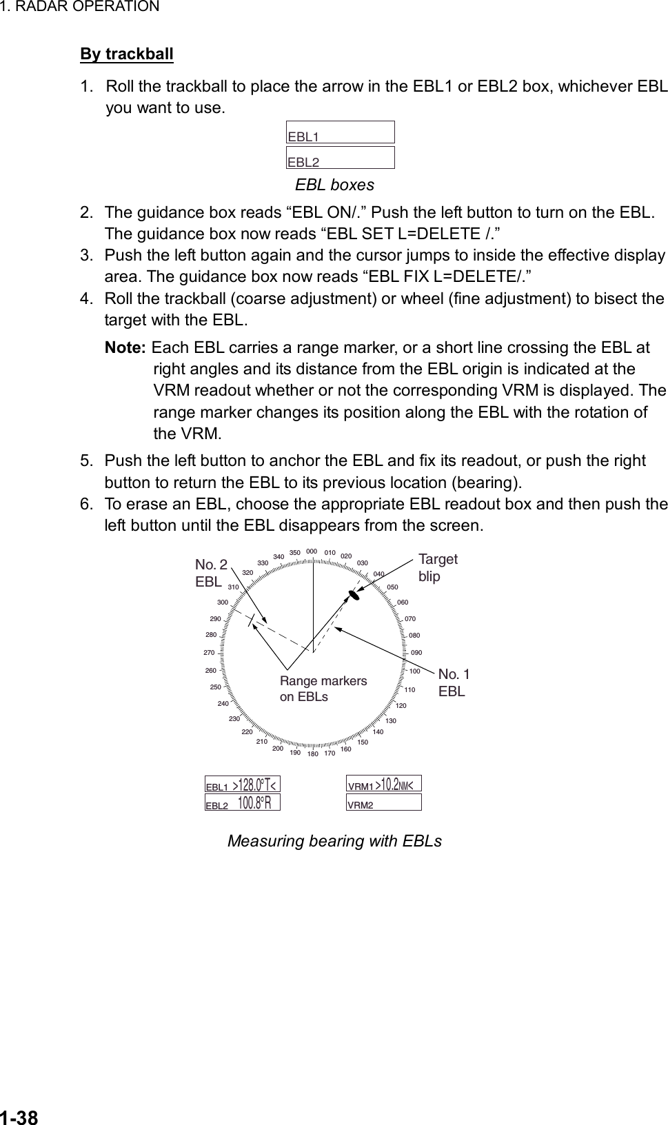
![1. RADAR OPERATION 1-39 [MARK MENU] 1 BACK 2 OWN SHIP MARK OFF/ON 3 STERN MARK OFF/ON 4 INDEX LINE BEARING REL/TRUE 5 INDEX LINE 1/2/3/6 6 INDEX LINE MODE VERTICAL/HORIZONTAL 7 8 EBL OFFSET BASE POINT STAB GND/STAB HDG/ STAB NORTH 9 EBL CURSOR BEARING REL/TRUE 0 RING OFF/ON 1.21.2 Choosing true or relative bearing The EBL readout is affixed by “R.” (relative) if it is relative to own ship's heading, .”T.” (true) if it is referenced to the north. You may choose relative or true in the head-up modes; in all other modes it is always TRUE. To choose bearing reference in the head-up mode, do the following: 1. Roll the trackball to choose the MENU box and then push the left button to open the MAIN menu. 2. Roll the wheel to choose 2 MARK and then push the wheel or the left button to open the MARK menu. MARK menu 3. Roll the wheel to choose 9 EBL CURSOR BEARING and then push the wheel or the left button. 4. Roll the wheel to choose REL or TRUE as appropriate and then push the wheel or the left button. 5. Push the right button twice to close the menu. Note: When the gyrocompass heading changes, the EBL and its indication change as follows: Head-up, relative: EBL indication and EBL remain unchanged. Head-up, true: EBL indication remains the same; EBL moves. Course-up, true: EBL indication and EBL remain unchanged. North-up, true: EBL indication and EBL remain unchanged.](https://usermanual.wiki/Furuno-USA/9ZWRTR078/User-Guide-356443-Page-57.png)
![1. RADAR OPERATION 1-40 1.22 Collision Assessment by Offset EBL The origin of the EBL can be placed anywhere with the trackball to enable measurement of range and bearing between any targets. This function is also useful for assessment of the potential risk of collision. It is possible to read CPA (Closest Point of Approach) by using a VRM as shown below (Figure (a)). If the EBL passes through the sweep origin (own ship) as illustrated (Figure (b)), the target ship is on a collision course. 1.22.1 How to assess risk of collision by the offset EBL By keyboard 1. Press the [EBL ON] key to display or activate an EBL (No. 1 or No. 2). 2. Place the cursor (+) on a target appearing as threatening (A in the illustrated example on the next page) by operating the trackball. 3. Press the [EBL OFFSET] key, and the origin of the active EBL shifts to the cursor position. Press the [EBL OFFSET key] again to anchor the EBL origin. 4. After waiting for a few minutes (at least 3 minutes), operate the EBL rotary control until the EBL bisects the target at the new position (A'). The EBL readout shows the target ship's course, which may be true or relative depending on the EBL bearing reference setting. Note: If relative motion is selected, it is also possible to read CPA by using a VRM as shown in left-hand figure at the top of the next page. If the EBL passes through the sweep origin (own ship) as illustrated in the right-hand figure at the top of then next page, the target ship is on a collision course. 5. To return the EBL origin to the own ship's position, press the [EBL OFFSET] key twice. By trackball 1. Display an EBL, following steps 1-3 in “By trackball” in paragraph 1.21.1. 2. With the cursor inside the effective display area, push the left button, roll the wheel to show “EBL OFFSET / EXIT” in the guidance box and then push the left button. 3. Roll the trackball to place the offset EBL on a target appearing as threatening (A in the illustrated example on the next page) and then push the left button to anchor the EBL origin. 4. After waiting for a few minutes (at least 3 minutes), operate the EBL used in step 1 until it bisects the target at the new position (A'). The EBL readout shows the target ship's course, which may be true or relative depending on the EBL bearing reference setting. To return the EBL origin to the screen center, show “EBL OFFSET / EXIT” in the guidance window and then push the left button.](https://usermanual.wiki/Furuno-USA/9ZWRTR078/User-Guide-356443-Page-58.png)
![1. RADAR OPERATION 1-41 [MARK MENU] 1 BACK 2 OWN SHIP MARK OFF/ON 3 STERN MARK OFF/ON 4 INDEX LINE BEARING REL/TRUE 5 INDEX LINE 1/2/3/6 6 INDEX LINE MODE VERTICAL/HORIZONTAL 7 8 EBL OFFSET BASE POINT STAB GND/STAB HDG/ STAB NORTH 9 EBL CURSOR BEARING REL/TRUE 0 RING OFF/ON 000 010 020030040050060070080090100110120130140150160170180190200210220230240250260270280290300310320330340 350000 010 020030040050060070080090100110120130140150160170180190200210220230240250260270280290300310320330340 350No. 1 VRMAA1AA1No. 1EBLNo. 1EBL EBL1 >150.3 T< VRM1 >3.85NM< EBL1 >150.3 T< Collision assessment by offset EBL 1.22.2 Choosing point of reference for origin point of offset EBL The origin point of the offset EBL can be ground stabilized (geographically fixed) or referenced to own ship’s heading (relative). 1. Roll the trackball to choose the MENU box and then push the left button. 2. Roll the wheel to choose 2 MARK and then push the wheel or the left button to display the MARK menu. MARK menu 3. Roll the wheel to choose 8 EBL OFFSET BASE POINT and then push the wheel or the left button. 4. Roll the wheel to choose STAB GND, STAB HDG or STAB NORTH as appropriate and then push the wheel or the left button. 5. Push the right button twice to close the menu.](https://usermanual.wiki/Furuno-USA/9ZWRTR078/User-Guide-356443-Page-59.png)
![1. RADAR OPERATION 1-42 1.23 Measuring Range and Bearing Between Two Targets By keyboard 1. Press the [EBL OFFSET] key. Operate the trackball to place the origin of the No. 1 EBL, for example, on a target of interest (target 1 in the illustrated example). 2. Operate the EBL rotary control until the EBL passes through another target of interest (target 2). 3. Operate the VRM rotary control until the range marker on the EBL is on the inside edge of target 2. The active VRM readout at the lower-right corner of the screen indicates the distance between the two targets. 4. You can repeat the same procedure on third and fourth targets (targets 3 and 4) by using the No. 2 EBL and the No. 2 VRM. Bearing is shown relative to own ship with suffix “R” or as a true bearing with suffix “T” depending on EBL relative/true settings of EBL CURSOR BEARING in the MARK menu. To return the EBL origin to the screen center, press the [EBL OFFSET] key again. By trackball 1. Display an EBL, following steps 1-3 in “By trackball” in paragraph 1.21.1. 2. With the cursor inside the effective display area, push the left button, roll the wheel to show “EBL OFFSET / EXIT” in the guidance box and then push the left button. 3. Roll the trackball to place the cursor on target 1 and then push the wheel. 4. Operate the No. 1 VRM until the range marker on the EBL aligns with target 2. The active VRM readout at the lower-right corner of the screen indicates the distance between the two targets. 5. You can repeat the same procedure on third and fourth targets (targets 3 and 4) by using the No. 2 EBL and the No. 2 VRM. 000 010 020030040050060070080090100110120130140150160170180190200210220230240250260270280290300310320330340 350EBLorigin No. 1 VRM No. 2 VRM R2Target 2No.1EBLNo. 2EBLRangeMarkerRange/bearingbetween targets1 and 2Range/bearingbetween targets 3 and 4 EBL1 EBL2 >140.0 R<335.2 R VRM1 VRM2 >0.50NM<0.98NMRangeMarkerTarget 4Target 3Target 1 Measuring range and bearing between two targets To return the EBL origin to the screen center, show “EBL OFFSET / EXIT” in the guidance window and then push the left button.](https://usermanual.wiki/Furuno-USA/9ZWRTR078/User-Guide-356443-Page-60.png)
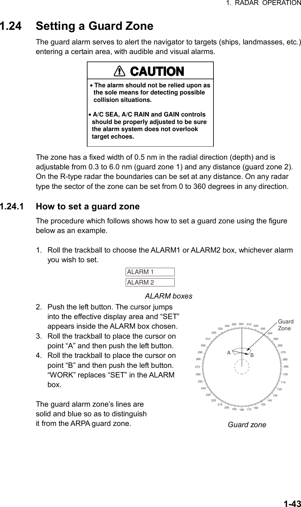
![1. RADAR OPERATION 1-44 Note 1: If you wish to create a guard alarm zone having a 360-degree coverage around own ship, set point “B” in almost the same direction as point “A.” Note 2: Two alarm zones may be set. Note however that the 2nd guard alarm zone is available only when the 1st guard alarm zone is active. Note 3: When the guard zone is not within the range in use the indication UP RNG appears to the right of the ALARM box. In this case choose a range which will display the guard alarm zone. 1.24.2 Acknowledging the alarm A target in the guard zone produces both visual (flashing) and audible (beep) alarms. To silence the audible alarm, press the [ALARM ACK] key on the full keyboard or choose the ALARM box and then push the left button. The ALARM box shows “ALARMx ACK.” This will deactivate the audible alarm but will not stop the flashing of the offending target. To reactivate the audible alarm, press the [ALARM ACK] key again or choose the ALARM ACK box and then push the left button. (When an external buzzer is connected, the audible alarm does not stop until the alarm zone itself is deactivated.) The ALARM box shows “ALARMx WORK.” 1.24.3 Deactivating a guard zone 1. Roll the trackball to choose the ALARM1 or ALARM2 box, whichever alarm you wish to deactivate. 2. Push the left button until the alarm status in the ALARM box disappears. In the IMO type radar deactivation of the guard zone 1 deactivates guard zone 2. Guard zones 1 and 2 work independent on the R-type radar.](https://usermanual.wiki/Furuno-USA/9ZWRTR078/User-Guide-356443-Page-62.png)
![1. RADAR OPERATION 1-45 [ALARM MENU] 1 BACK 2 GUARD ALARM MODE IN/OUT 3 GUARD ALARM LEVEL 1/2/3/4 4 WATCH ALARM OFF/6MIN/10MIN/ 12MIN/15MIN/20MIN 5 ALARM SOUND LEVEL LOW/MID/HIGH 6 [ALARM OUT1] 7 [ALARM OUT2] 8 [ALARM OUT3] 1.24.4 Guard alarm attributes You may choose the echo strength level which triggers the alarm, the condition which generates the guard alarm and the volume of the audible alarm as follows: 1. Roll the trackball to choose the MENU box at the right side of the screen and then push the left button. 3. Roll the wheel to choose 3 [ALARM] and then push the wheel or the left button. ALARM menu 4. Roll the wheel to choose 2 GUARD ALARM MODE and then push the wheel or the left button. 5. Roll the wheel to choose IN (guard zone) or OUT (anchor watch) as appropriate and then push the wheel or the left button. Inward guard alarm Outward guard alarm Alarm types 6. Roll the wheel to choose 3 GUARD ALARM LEVEL and then push the wheel or the left button. 7. Roll the wheel to choose echo strength level which will trigger the alarm and then push the wheel or the left button. “4” is highest strength. 8. Roll the wheel to choose 5 ALARM SOUND LEVEL and then push the wheel or the left button. 9. Roll the wheel to choose audible alarm volume, from among LOW, MID and HIGH, and then push the wheel or the left button. Note: 5 ALARM SOUND LEVEL also sets the level of the audible alarm for the watch alarm. 10. Push the right button twice to close the menu.](https://usermanual.wiki/Furuno-USA/9ZWRTR078/User-Guide-356443-Page-63.png)
![1. RADAR OPERATION 1-46 1.25 Off-Centering the Display Own ship position, or sweep origin, can be displaced to expand the view field without switching to a larger range scale. The sweep origin can be off-centered to the cursor position, but not more than 75% of the range in use; if the cursor is set beyond 75% of the range scale, the sweep origin will be off-centered to the point of 75% of the limit. This feature is not available on the 72 nm or 96 nm range scale nor in the true motion mode. To off-center the radar picture, do the following: By keyboard 1. Roll the trackball to place the cursor at a position where you wish to move the sweep origin. 2. Press the [OFF CENTER] key. Then, the sweep origin is off-centered to the cursor position. 3. To cancel off-centering, press the [OFF CENTER] key again. By trackball 1. With the cursor inside the effective display area, roll the wheel to display “OFF CENTER / EXIT” in the guidance box and then push the wheel or the left button. 2. Roll the trackball to place the cursor where you want to locate the screen center. 3. Push the left button to off center the sweep origin. 4. To cancel the off-center function, push the left button when the guidance box reads “OFF CENTER / EXIT.” CursorPlace cursor where desiredand execute appropriateOFF CENTER procedure Off-centered display How to off-center the display](https://usermanual.wiki/Furuno-USA/9ZWRTR078/User-Guide-356443-Page-64.png)
![1. RADAR OPERATION 1-47 [PICTURE MENU] 1 INT REJECT OFF/1/2/3 2 ECHO STRETCH OFF/1/2/3 3 ECHO AVERAGE OFF/1/2/3 4 NOISE REJ OFF/ON 5 AUTO STC OFF/ON 6 AUTO RAIN OFF/ON 7 VIDEO CONTRAST A/B/C/D 8 [PULSE] 9 [CONDITION] 0 DEFAULT 1.26 Echo Stretch The echo stretch feature enlarges targets to make them easier to see, and it is available on the 1.5 -12 nm ranges depending on echo stretch type. There are 3 settings: ES1 to enlarge in bearing direction for long range detection, ES2 to enlarge in range direction and ES3 to enlarge in bearing and range directions. Echo Stretch 1 Echo Stretch 2 Echo Stretch 3BearingdirectionRangedirection Echo Stretch OFFTargetBearingdirectionRangedirectionUse on range1.5 - 12 nmUse on range1.5 - 6 nm Echo stretch Note 1: If the 1.5 nm is preset with a pulselength of S1 or S2, and the 3 nm scale with S2, the echo stretch is not available on those range scales. Note 2: The echo stretch magnifies not only small target pips but also returns (clutter) from sea surface, rain and radar interference. For this reason, make sure these types of interference have been sufficiently suppressed before activating the echo stretch. 1. Roll the trackball to choose the PICTURE box at the left side of the display. 2. Push the right button to show the PICTURE menu. PICTURE menu 3. Roll the wheel to choose 2 ECHO STRETCH and then push the wheel or the left button. 4. Roll the wheel to choose desired echo stretch and then push the left button. 5. Push the right button to close the menu.](https://usermanual.wiki/Furuno-USA/9ZWRTR078/User-Guide-356443-Page-65.png)
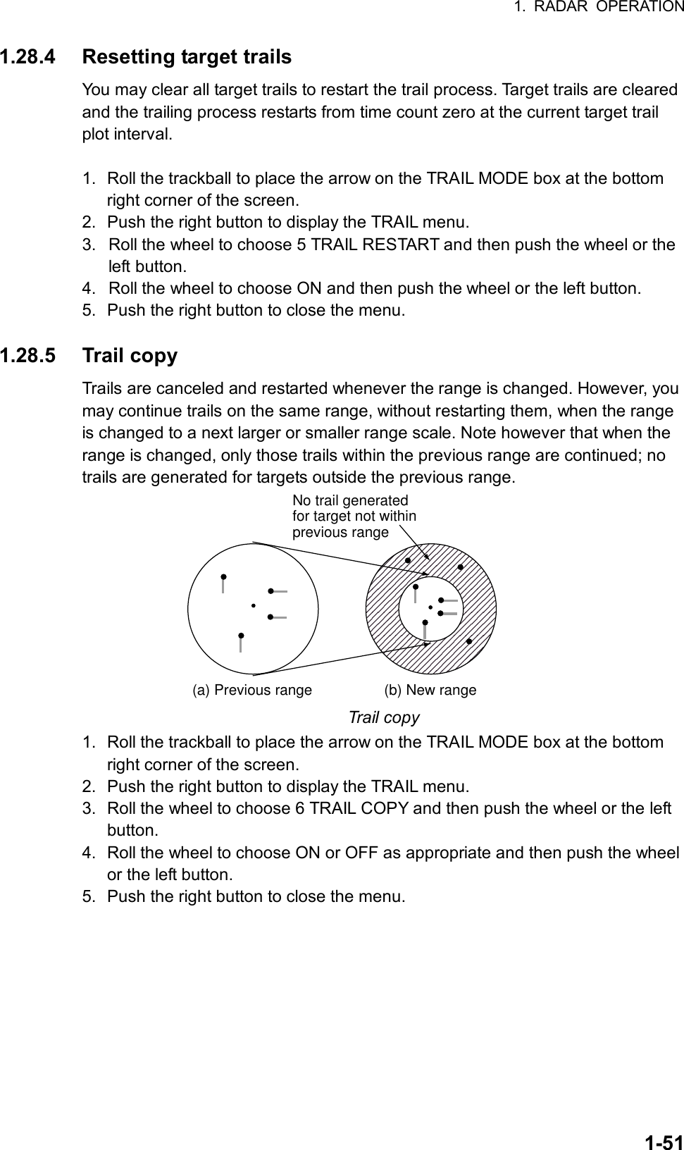
![1. RADAR OPERATION 1-49 [TRAIL MENU] 1 TRAIL MODE REL/TRUE/PAST ECHO2 TRAIL GRAD SINGLE/MULTI 4 TRAIL LEVEL 1/2/3/4 5 TRAIL RESTART OFF/ON 6 TRAIL COPY OFF/ON 7 OS TRAIL OFF/ON 1.28 Target Trails The trails of the radar echoes of targets may be displayed in the form of synthetic afterglow. Target trails are chosen either relative or true and may be sea or ground stabilized. True motion trails require a compass signal and own ship speed input. 1.28.1 True or relative trails You may display echo trails in true or relative motion (only true trail on TM). Relative trails show relative movements between targets and own ship. True motion trails require a gyrocompass signal and own ship speed input to cancel out own ship's movement and present true target movements in accordance with their over-the-ground speeds and courses. (a) True target trails (No smearing of stationary targets)(b) Relative target trails Targets moving relative to own ship Target trails Note: When true trail is selected on the RM mode, the TRAIL MODE box is shown in red. No true-relative selection on TM; it is only True trails on TM mode. 1. Roll the trackball to place the arrow on the TRAIL MODE box at the bottom right corner of the screen and then push the right button to open the TRAIL menu. TRAIL menu](https://usermanual.wiki/Furuno-USA/9ZWRTR078/User-Guide-356443-Page-67.png)
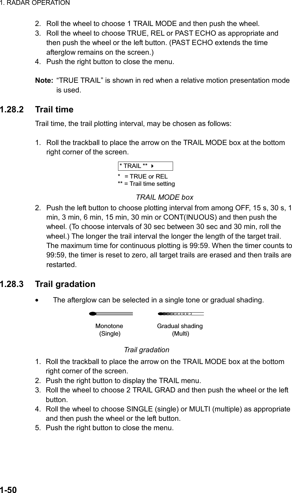
![1. RADAR OPERATION 1-52 1.28.6 Trail level The level (intensity) of the afterglow which extends from radar targets may be chosen as below. 1. Roll the trackball to place the arrow on the TRAIL MODE box at the bottom right corner of the screen. 2. Push the right button to display the TRAIL menu. 3. Roll the wheel to choose 4 TRAIL LEVEL and then push the wheel or the left button. 4. Roll the wheel to choose level desired and then push the wheel or the left button. The higher the number the stronger the afterglow. 5. Push the right button to close the menu. 1.28.7 Canceling trails Trails can be canceled as follows: By keyboard Press the [CANCEL TRAILS] key. By trackball 1. Roll the trackball to place the arrow on the TRAIL MODE box at the bottom right corner of the screen. 2. Push the left button to choose OFF.](https://usermanual.wiki/Furuno-USA/9ZWRTR078/User-Guide-356443-Page-70.png)
![1. RADAR OPERATION 1-531.29 Parallel Index Lines Parallel index lines are useful for keeping a constant distance between own ship and a coastline or a partner ship when navigating. Six index lines are available and any two may be displayed. You may control the orientation and line interval. Indexlines Parallel index lines 1.29.1 Displaying, erasing parallel index lines By keyboard 1. With the menu closed, press the [INDEX LINE] key. The guidance box shows “DISP INDEX LINE/.” 2. While watching the IL (Index Line) box at the left side of the screen, press the [INDEX LINE] key momentarily to choose the index line number (IL1 or IL2) to display. If you want to erase the chosen index line, press and hold down the key until the index line disappears from the screen. Index line number Status (ON or OFF)IL 1 ON032.0 T5.60NMIndex line orientation,Index line interval(Neither shown whenIndex line is OFF.) IL (Index Line) box By trackball 1. Roll the trackball to place the arrow in the IL box at the lower left-hand side of the screen. (See the illustration above.) 2. Roll the wheel to choose index line number and then push the left button or the wheel to turn the index line on or off as appropriate.](https://usermanual.wiki/Furuno-USA/9ZWRTR078/User-Guide-356443-Page-71.png)
![1. RADAR OPERATION 1-54 [MARK MENU] 1 BACK 2 OWN SHIP MARK OFF/ON 3 STERN MARK OFF/ON 4 INDEX LINE BEARING REL/TRUE 5 INDEX LINE 1/2/3/6 6 INDEX LINE MODE VERTICAL/HORIZONTAL 7 8 EBL OFFSET BASE POINT STAB GND/STAB HDG/ STAB NORTH 9 EBL CURSOR BEARING REL/TRUE 0 RING OFF/ON 1.29.2 Adjusting index line orientation, index line interval 1. Display the index line for which you want to adjust its orientation, referring to paragraph 1.29.1. 2. Roll the trackball to place the arrow in the index line orientation setting window, directly below the IL box. IL 1 ON032.0 T5.60NMIndex line orientationIndex line interval Index line data 3. Roll the wheel to adjust the index line orientation, between 000.0-359.9(°T). 4. Roll the trackball to place the cursor in the index line interval setting window. 5. Roll the wheel to adjust the index line interval, between -24 - + 24 (nm). 1.29.3 Index line bearing reference Index line bearing reference may be relative to own ship’s heading (Relative) or referenced to North (True) as follows: 1. Roll the trackball to choose the MENU box at the right side of the screen and then push the left button. 2. Roll the wheel to choose 2 MARK and then push the wheel or the left button to display the MARK menu. MARK menu 3. Roll the wheel to choose 4 INDEX LINE BEARING and then push the wheel or the left button. 4. Roll the wheel to choose TRUE or REL as appropriate and then push the wheel or the left button. 5. Push the right button twice to close the menu.](https://usermanual.wiki/Furuno-USA/9ZWRTR078/User-Guide-356443-Page-72.png)
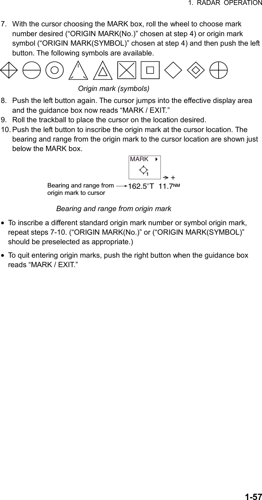
![1. RADAR OPERATION 1-56 [MARK MENU] 1 ORIGIN MARK STAB GND/SEA 2 ORIGIN MARK(No.)/ ORIGIN MARK(SYMBOL)/ MAP MARK/ WP 1~50/ WP 51~100/ WP 101~150/ WP 151~200/ OWN SHIP SHAPE 9 MAP DISPLAY OFF/ON 0 MAP MARK COLOR* RED/GRN/BLU/YEL/ CYA/MAG/WHT 1.30 Origin Mark You can mark any prominent target or a point of particular interest using the origin mark feature. Twenty origin marks may be entered: 10 standard origin marks (with number) and one each of the 10 symbol origin marks. The marks may be geographically fixed (ground stabilized) or sea stabilized. To display the origin marks, heading signal and own ship position data are required. 1.30.1 Entering origin marks 1. Roll the trackball to choose the MARK box at the left side of the screen. The guidance box now reads “MARK SELECT / MARK MENU.” MARK Mark type lastselected, marknumber> +162.5 T 11.7 NMBearing and range from own ship to origin mark1 MARK box 2. Push the right button to open the MARK menu. MARK menu 3. Roll the wheel to choose “2” and then push the wheel or the left button. 4. Roll the wheel to choose ORIGIN MARK(No.) or ORIGIN MARK(SYMBOL) as appropriate and then push the wheel or the left button. Choose ORIGIN MARK(No.) to inscribe standard origin mark ( ) plus mark number; ORIGIN MARK(SYMBOL) to inscribe desired origin mark symbol (no number). 5. Push the left button. 6. Push the right button to close the menu. The guidance box now reads “MARK SELECT / MARK MENU.” * Not available on IMO radar.](https://usermanual.wiki/Furuno-USA/9ZWRTR078/User-Guide-356443-Page-74.png)
![1. RADAR OPERATION 1-58 [MARK MENU] 1 ORIGIN MARK STAB GND/SEA 2 ORIGIN MARK(No.)/ ORIGIN MARK(SYMBOL)/ MAP MARK/ WP 1~50/ WP 51~100/ WP 101~150/ WP 151~200/ OWN SHIP SHAPE 9 MAP DISPLAY OFF/ON 0 MAP MARK COLOR* RED/GRN/BLU/YEL/ 1.30.2 Origin mark stabilization Origin marks may be geographically fixed (ground stabilized) or moving (sea stabilized). 1. Roll the trackball to choose the MARK box. 2. Push the right button to open the MARK menu. MARK menu 3. Roll the wheel to choose 1 ORIGIN MARK STAB and then push the wheel. 4. Roll the wheel to choose GND or SEA as appropriate and then push the wheel or the left button. 5. Push the right button to close the menu.. 1.30.3 Deleting individual origin marks The procedure below shows how to delete individual origin marks. Note that origin marks cannot be deleted collectively. 1. With the cursor inside the effective display area, roll the wheel to display “MARK DELETE / EXIT” in the guidance box. 2. Roll the trackball to place the cursor on the origin mark you wish to erase. A flashing “X” appears on the mark when it is correctly selected. 3. Push the left button or the wheel to erase the mark. 4. To erase another mark, repeat steps 2 and 3. 5. To finish, push the right button when the guidance box reads “MARK DELETE / EXIT.” *: Not available on IMO radar.](https://usermanual.wiki/Furuno-USA/9ZWRTR078/User-Guide-356443-Page-76.png)
![1. RADAR OPERATION 1-60 1.32 Markers 1.32.1 Heading marker and heading line The heading marker and the heading line indicate the ship's heading in all presentation modes. The heading line is a line from the own ship position to the outer edge of the radar display area and appears at zero degrees on the bearing scale in head-up mode; it changes the orientation depending on the ship orientation in north-up and true motion modes. The heading marker is a small circle on the bearing scale to indicate the heading when the display is off-centered or is in north-up or TM mode. Temporarily erasing the heading line To temporarily extinguish the heading line to look at targets existing dead ahead of own ship, press the [HL OFF] key on the keyboard, or roll the trackball to choose the HL OFF box at the bottom left corner of the display and then push the left button. In addition to the heading line, the stern marker and all graphics within the effective display are also erased. To redisplay the heading line, etc., release the key or the left button. 1.32.2 Stern marker The stern marker, which is a dot-and-dash line, appears opposite to the heading line. To display or erase this marker do the following: 1. Roll the trackball to choose the MENU box at the right side of the display and then push the left button to display the MAIN menu. 2. Roll the wheel to choose MARK and then push the wheel or the left button to show the MARK menu. 3. Roll the wheel to choose 3 STERN MARK and then push the wheel or the left button. 4. Roll the wheel to choose OFF or ON as appropriate and then push the wheel or the left button. 5. Push the right button twice to close the menu. 1.32.3 North marker The north marker appears as a short dashed line. In the head-up mode, the north marker moves around the bearing scale in accordance with the compass signal.](https://usermanual.wiki/Furuno-USA/9ZWRTR078/User-Guide-356443-Page-78.png)
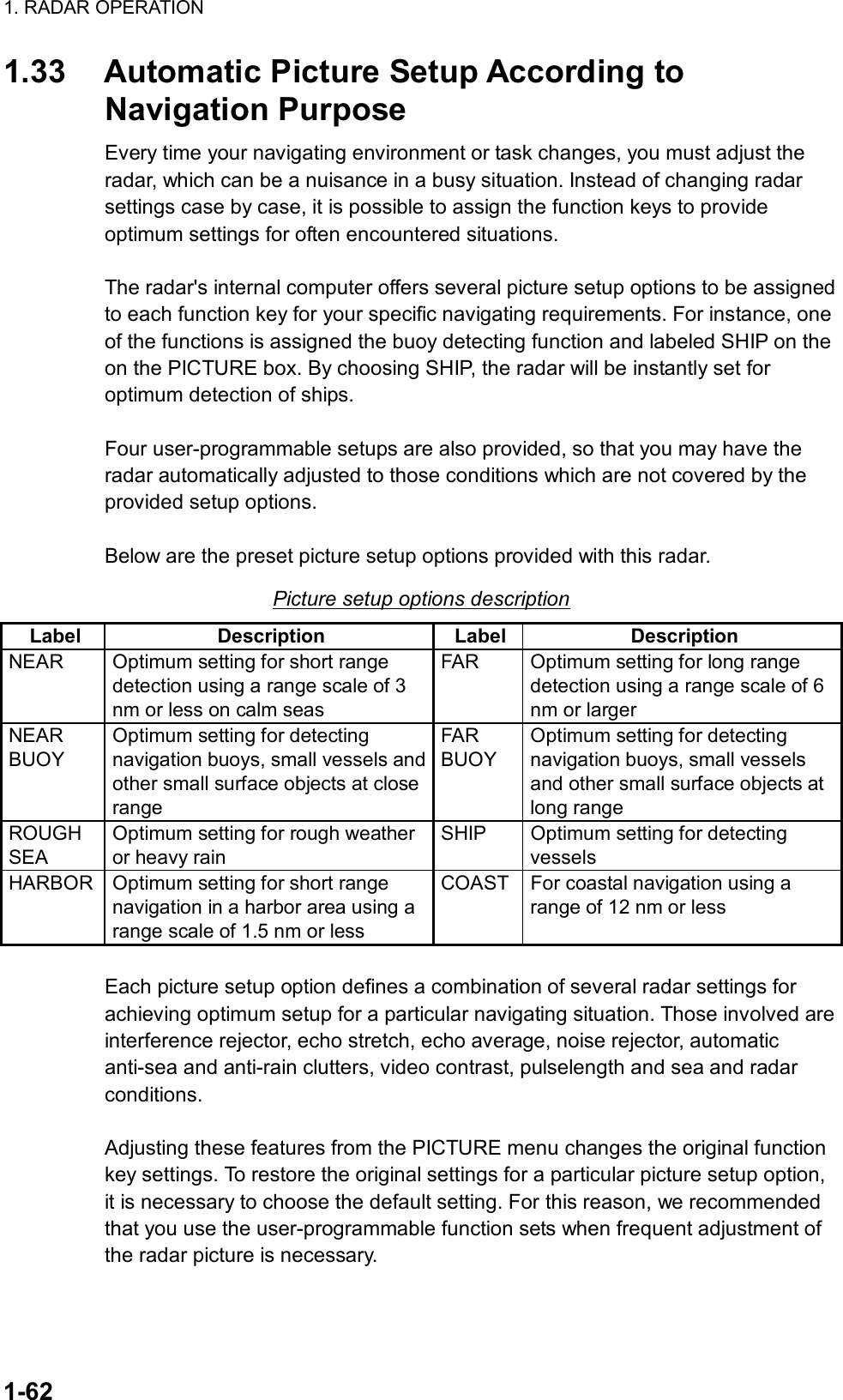
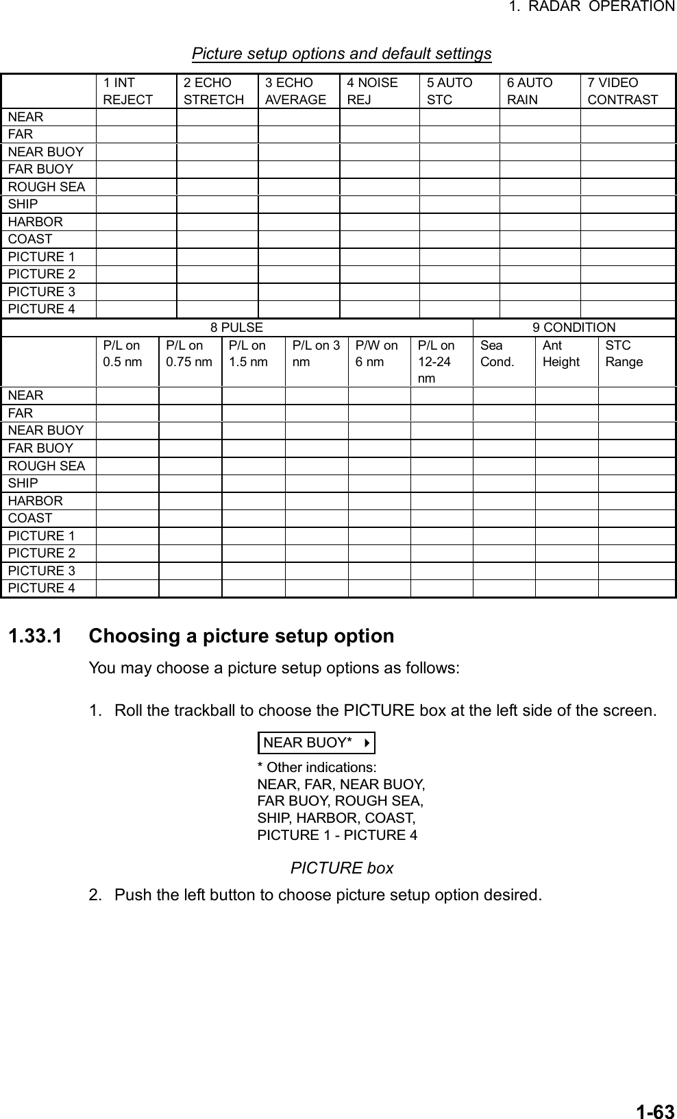
![1. RADAR OPERATION 1-64 [PICTURE MENU] 1 INT REJECT OFF/1/2/3 2 ECHO STRETCH OFF/1/2/3 3 ECHO AVERAGE OFF/1/2/3 4 NOISE REJ OFF/ON 5 AUTO STC OFF/ON 6 AUTO RAIN OFF/ON 7 VIDEO CONTRAST A/B/C/D 8 [PULSE] 9 [CONDITION] 0 DEFAULT 1.33.2 Restoring default picture setup options Any of the radar functions programmed with the picture setup options may be adjusted as desired. If you get lost in operation and want to restore the default settings for a particular picture setup operation, do the following: 1. Roll the trackball to choose the PICTURE box at the left side of the screen. NEAR BUOY* * Other indications:NEAR, FAR, NEAR BUOY,FAR BUOY, ROUGH SEA,SHIP, HARBOR, COAST,PICTURE 1 - PICTURE 4 PICTURE box 2. Push the left button to choose the picture setup option for which you want to restore its default settings. 3. Push the right button to show the PICTURE menu. PICTURE menu 4. Roll the wheel to choose 0 DEFAULT and then push the wheel. 5. Push the wheel or the left button three times to restore default settings for the picture setup selected. (If you are using the keyboard, press the [ENTER MARK] key three times.) 6. Push the right button to close the menu. Then, all default settings for the picture option chosen are restored.](https://usermanual.wiki/Furuno-USA/9ZWRTR078/User-Guide-356443-Page-82.png)
![1. RADAR OPERATION 1-65 [PICTURE MENU] 1 INT REJECT OFF/1/2/3 2 ECHO STRETCH OFF/1/2/3 3 ECHO AVERAGE OFF/1/2/3 4 NOISE REJ OFF/ON 5 AUTO STC OFF/ON 6 AUTO RAIN OFF/ON 7 VIDEO CONTRAST A/B/C/D 8 [PULSE] 9 [CONDITION] 0 DEFAULT 1.33.3 User-programmable picture setups Four user-programmable picture setups are provided and they are labeled PICTURE 1 – PICTURE 4 in the PICTURE box. You may program them as follows: 1. Roll the trackball to choose the PICTURE box at the left side of the screen. 2. Push the left button to choose PICTURE 1, PICTURE 2, PICTURE 3 or PICTURE 4, whichever you wish to set. 3. Push the right button to show the PICTURE menu. PULSE menu 4. Set items 1-6 and 8 referring to the following paragraphs: 1 INT REJECT: 1.19 2 ECHO STRETCH: 1.26 3 ECHO AVERAGE: 1.27 4 NOISE REJ: 1.36 5 AUTO STC: 1.17 6 AUTO RAIN: 1.18 8 PULSE: 1.15 5. Roll the wheel to choose 7 VIDEO CONTRAST and then push the wheel or the left button. 6. Roll the wheel to choose A, B, C or D as appropriate and then push the wheel or the left button. Option Objective A: Float detection, general navigation, reducing sea reflections B: Target discrimination C: Long range detection, buoy detection D: Long range detection (longer than C), buoy detection](https://usermanual.wiki/Furuno-USA/9ZWRTR078/User-Guide-356443-Page-83.png)
![1. RADAR OPERATION 1-66 [CONDITION MENU] 1 BACK 2 SEA CONDITION 1/2/3/4/5 3 ANT HEIGHT 5/7/5/10/15/20/ 25/30/35/40/45/ more50m 4 STC RANGE +00 7. Roll the wheel to choose 9 [CONDITION] and then push the wheel to show the CONDITION menu. CONDITION menu 8. Roll the wheel to choose 2 SEA CONDITION and then push the wheel or the left button. 9. Roll the wheel to choose appropriate sea condition and then push the wheel or the left button. The larger the number the rougher the sea state. 10. Roll the wheel to choose 3 ANT HEIGHT and then push the wheel or the left button. 11. Roll the wheel to choose appropriate radar antenna height (above the waterline) and then push the wheel or the left button. 12. If necessary, roll the wheel to choose 4 STC RANGE, to adjust effective STC range, and then push the wheel or the left button. The setting range is –10 to +10. The larger the number the longer the effective STC range becomes. Roll the wheel to set and then push the wheel or the left button. (Note that the keyboard cannot be used to enter the setting.) 12. Push the right button twice to close the menu.](https://usermanual.wiki/Furuno-USA/9ZWRTR078/User-Guide-356443-Page-84.png)
![1. RADAR OPERATION 1-67 [CUSTOMIZE•TEST MENU] 1 BACK 2 [DATA BOX] 3 [F1] 4 [F2] 5 [F3] 6 [F4] 7 [OPERATION] 8 [TEST] 1.34 Programming Function Keys Less-often used functions are provided in the menu. To avoid opening the menus to set up the radar for a particular situation, function keys F1-F4 may be assigned any of the functions shown in the CUSTOMIZE•TEST sub menu. 1.34.1 Activating a function key To activate the function assigned to a function key, press the key to instantly set the radar for the preset purpose. Further press the key to choose option. Function key Default setting F1 F2 F3 F4 1.34.2 Programming the functions keys Do the following to program the function keys. 1. Roll the trackball to choose the MENU box at the right side of the display and then push the left button to display the MAIN menu. 2. Roll the wheel to choose 9 [CUSTOMIZE•TEST] and then push the wheel. CUSTOMIZE•TEST menu](https://usermanual.wiki/Furuno-USA/9ZWRTR078/User-Guide-356443-Page-85.png)
![1. RADAR OPERATION 1-68 [F1] 1 BACK 2 [ECHO] 3 [STD KEY] 4 [ARPA•AIS] 5 [OPERATION] [ECHO] 1 BACK 2 PICTURE/ IR ES/ EAV/ NOISE REJ/ ANT SELECT/ PULSE LENGTH/ A/C SEA SELECT/ A/C RAIN SELECT/ TUNE SELECT/ ANT HEIGHT/ SEA CONDITION/ 2ND ECHO REJ/ [ARPA•AIS] 1 BACK 2 DISP ARPA/ DISP AIS/ TARGET DATA & ACQ/ PAST POSN INTERVAL/ REF MARK/ CPA LIMIT/ CPA/TCPA/ GZ1/GZ2/ TARGET LIST SORT/ TRIAL MANEUVER/ ARPA•AIS FUSION/ AIS MESSAGE [STD KEY] 1 BACK 2 ALARM ACK/ STBY TX/ HL OFF/ EBL OFFSET/ MODE/ OFF CENTER/ CU TM RESET/ INDEX LINE/ VECTOR TIME/ VECTOR MODE/ TARGET LIST/ TRAIL/BRILL/ MARK/ MENU/ RANGE UP/ RANGE DOWN/ ACQ/ [OPERATION] 1 BACK 2 ECHO COLOR/ BACK COLOR/ RING/ ALARM1/ ALARM2/ WATCH ALARM RESET/ ZOOM/ MARK DELETE/ CHART ALIGN/ DISPLAY SELECT/ MOB/ USER DEFAULT/ TLL 3. Roll the wheel to choose 3 [F1], 4 [F2], 5 [F3] or 6 [F4], whichever function key you want to set, and then push the wheel or the left button. For example, choose 3 [F1] and then push the left button. F1 menu 4. Roll the wheel to choose appropriate category, ECHO, STD KEY, ARPA•AIS or OPERATION and then push the wheel or the left button. Refer to the menus below to choose appropriate category. Function key categories and options](https://usermanual.wiki/Furuno-USA/9ZWRTR078/User-Guide-356443-Page-86.png)
![1. RADAR OPERATION 1-695. Roll the wheel to choose “2” and then push the wheel or the left button. 6. Roll the wheel to choose function desired and then push the wheel or left button. 7. Push the right button twice to close the menu. Description of function key programs Item Description [ECHO] PICTURE Chooses picture setup function. IR Chooses interference rejection level. ES Chooses echo stretch function. EAV Chooses echo averaging function. NOISE REJ Turns noise rejector on/off. ANT SELECT Chooses antenna. PULSE LENGTH Chooses pulselength. A/C SEA SELECT Chooses A/C SEA adjustment method. A/C RAIN SELECT Chooses A/C RAIN adjustment method. TUNE SELECT Chooses tuning adjustment method. ANT HEIGHT Sets antenna height. SEA CONDITION Sets sea condition. 2ND ECHO REJ Turns 2nd trace echo rejector on/off. PM Turns performance monitor on/off. SART Turns SART setup conditions on/off. [STD KEY] ALARM ACK Acknowledges alarm. (Silences audible alarm.) STBY TX Toggles between stand-by and transmit. HL OFF Turns heading line on/off. EBL OFFSET Offsets EBL. OFF CENTER Off centers the display. CU TM RESET Returns own ship mark to point 75% of range in use. INDEX LINE Turns index line on/off. VECTOR TIME Sets vector time. VECTOR MODE Sets vector mode. TARGET LIST Displays target list. TRAIL BRILL Adjusts trail brilliance. MARK Chooses mark to inscribe. MENU Opens the MAIN menu. RANGE UP Raises the range scale. RANGE DOWN Lowers the range scale. ACQ Acquires ARPA target; activate sleeping AIS target. TARGET CANCEL Cancels tracking of ARPA target; sleep AIS target.](https://usermanual.wiki/Furuno-USA/9ZWRTR078/User-Guide-356443-Page-87.png)
![1. RADAR OPERATION 1-70 Description of function key programs (con’t) Item Description [ARPA•AIS] DISP ARPA Activates/deactivates ARPA. DISP AIS Activates/deactivates AIS. TARGET DATA & ACQ ARPA: Acquires ARPA target; shows data for ARPA target selected. AIS: Activates sleeping AIS target; shows data for AIS target selected. PAST POSN INTERVAL Chooses past position plotting interval. REF MARK Inscribes reference mark (for target-based speed). CPA LIMIT Turns CPA limit on/off. CPA Enters CPA range. TCPA Enters TCPA time. GZ1 Sets Guard Zone 1. GZ2 Sets Guard Zone 2. TARGET LIST SORT Sorts target list. TRIAL MANEUVER Executes trial maneuver. ARPA•AIS FUSION Converts ARPA target to AIS target. AIS MESSAGE Displays AIS message board. [OPERATION] ECHO COLOR Chooses echo color. BACK COLOR Chooses background color. RING Turns range rings on/off. ALARM1 Sets no. 1 guard alarm. ALARM2 Sets no. 2 guard alarm. WATCH ALARM RESET Resets watch alarm. ZOOM Enables zoom. MARK DELETE Deletes mark (origin mark, waypoint mark, plotter mark). CHART ALIGN Aligns chart with radar picture. DISPLAY SELECT Chooses display mode. DEGAUSS Degausses picture. USER DEFAULT Restores default settings. TLL Outputs radar target’s L/L position to video plotter.](https://usermanual.wiki/Furuno-USA/9ZWRTR078/User-Guide-356443-Page-88.png)
![1. RADAR OPERATION 1-71 [OS POSN MENU] 1 NAV AID GPS1/GPS2/ DEAD RECKONING 2 MANUAL L/L 00°00.00 N 000°00.00 W 1.35 Ship’s Position Choose the source of ship’s position data as follows: 1. Roll the trackball to choose the OS POSN box at the top right corner of the screen. OS POSN OS POSN box 2. Push the right button to show the OS POSN menu. OS POSN menu 3. Roll the wheel to choose 1 NAV AID and then push the wheel or the left button. 4. Roll the wheel to choose GPS1, GPS2 or DEAD RECKONING as appropriate and then push the wheel or the left button. GPS1: GPS Navigator connected to nav port GPS2: GPS navigator connected to speed port or trackpilot port 5. If you have chosen DEAD RECKONING go to step 6 to enter position manually. For GPS1 or GPS2, go to step 7. 6. Roll the wheel to choose 2 MANUAL L/L and then push the wheel. Enter latitude and longitude position as follows: 1) Roll the wheel to set appropriate digit in the latitude field and then push the wheel. (You may push the wheel again to skip a place.) For keyboard operation, press appropriate numeric keys and then press the [ENTER MARK] key. 2) Set longitude similar to how you set latitude and then push the wheel. (For keyboard operation, press the [ENTER MARK] key.) Note: Co-ordinate polarity may be switched by rolling the wheel or pressing the [2] key in case of keyboard operation. 7. Push the right button to close the menu.](https://usermanual.wiki/Furuno-USA/9ZWRTR078/User-Guide-356443-Page-89.png)
![1. RADAR OPERATION 1-72 [PICTURE MENU] 1 INT REJECT OFF/1/2/3 2 ECHO STRETCH OFF/1/2/3 3 ECHO AVERAGE OFF/1/2/3 4 NOISE REJ OFF/ON 5 AUTO STC OFF/ON 6 AUTO RAIN OFF/ON 7 VIDEO CONTRAST A/B/C/D 8 [PULSE] 9 [CONDITION] 0 DEFAULT 1.36 Noise Rejector White noise may show itself on the screen as random “speckles” spread over the entire radar image. You can remove this noise as follows: 1. Roll the trackball to choose the PICTURE box at the left side of the screen. 2. Push the right button to open the PICTURE menu. PICTURE menu 3. Roll the wheel to choose 4 NOISE REJ and then push the wheel or the left button. 4. Roll the wheel to choose ON or OFF as appropriate and then push the wheel or the left button. 5. Push the right button to close the menu.](https://usermanual.wiki/Furuno-USA/9ZWRTR078/User-Guide-356443-Page-90.png)
![1. RADAR OPERATION 1-73 [ECHO MENU] 1 BACK 2 2ND ECHO REJ OFF/ON 3 TUNE INITIALIZE 4 PM OFF/ON 5 SART OFF/ON 6 WIPER OFF/1/21.37 Suppressing Second-trace Echoes In certain situations, echoes from very distance targets may appear as false echoes (second-trace echoes) on the screen. This occurs when the return echo is received one transmission cycle later, or after a next radar pulse has been transmitted. Second-traceechoTx repetitionActual rangeFalse echorange Second-trace echoes To reject second-trace echoes: 1. Roll the trackball to choose the MENU box at the right side of the screen and then push the left button. 2. Roll the wheel to choose 1 ECHO and then push the wheel or the left button to open the ECHO menu. ECHO menu 3. Roll the wheel to choose 2 2ND ECHO REJ and then push the wheel or the left button. 4. Roll the wheel to choose OFF or ON as appropriate and then push the wheel or the left button. 5. Push the right button twice to close the menu.](https://usermanual.wiki/Furuno-USA/9ZWRTR078/User-Guide-356443-Page-91.png)
![1. RADAR OPERATION 1-74 1.38 Adjusting Brilliance of Screen Data You can adjust relative brilliance levels of various markers and alphanumeric readouts displayed on the screen. 1. Roll the trackball to choose the BRILL box at the bottom left corner of the screen and then push the right button to show the BRILL menu. [BRILL1 MENU (2/2)]1 BACK2 BEARING CURSOR3 EBL4 VRM5 INDEX LINE6 ARPA SYMBOL7 AIS SYMBOL8 L/L GRID9 MARK0 CHARTChoose 0 NEXTto show page 2of the BRILL menu. [BRILL1 MENU (1/2)]1 ECHO COLOR YEL/GRN/ WHT/COLOR*2 BKGD COLOR BLK-GRN/ BLK-RED/ BLU-CIR/ BLU/BRT-BLU3 PANEL DIMMER4 CHARACTER5 CURSOR6 ECHO7 TRAIL8 HL9 RING0 NEXT* Not available on IMO radar.Note: Four brilliance and color sets are provided. For further details see paragraph 1.50. BRILL menu 2. Roll the wheel to choose item you wish to adjust and then push the wheel or the left button. (To go to the second page of the BRILL menu choose 0 NEXT and push the wheel.) Page 1 Page 2 Item Adjusts brilliance of; Item Adjusts brilliance of; 1 ECHO COLOR See para. 1.49. 2 BEARING CURSOR Bearing cursor 2 BKGD COLOR See para. 1.49. 3 EBL EBLs 3 PANEL DIMMER Backlighting of control unit 4 VRM VRMs 4 CHARACTERS All alphanumeric characters 5 INDEX LINE Index lines 5 CURSOR Cursor (+) and arrow 6 ARPA SYMBOL ARPA symbols 6 ECHO Radar echoes 7 AIS SYMBOL AIS symbols 7 TRAIL Target trails 8 L/L Chart grid 8 HL Heading line 9 MARK All marks 9 RING Range rings 0 CHART Chart 3. Roll the wheel to set brilliance level. The range of adjustment for items except “HL” is 0-100%. The range of adjustment for HL is 50-100%. 4. Push the right button once or twice to close the menu.](https://usermanual.wiki/Furuno-USA/9ZWRTR078/User-Guide-356443-Page-92.png)
![1. RADAR OPERATION 1-75 [ALARM MENU] 1 BACK 2 GUARD ALARM MODE IN/OUT 3 GUARD ALARM MODE 1/2/3/4 4 WATCH ALARM OFF/6MIN/10MIN/ 12MIN/15MIN/20MIN 5 ALARM SOUND LEVEL LOW/MID/HIGH 6 [ALARM OUT1] 7 [ALARM OUT2] 8 [ALARM OUT3] 1.39 Watch Alarm The watch alarm sounds the audible alarm at the chosen time interval to help you keep regular watch of the radar picture for safety or other purposes. The WATCH box appears at the lower-left corner of the screen with a watch alarm timer counts down from value set (for example, “12:00”). WATCH12:00 WATCH box When a preset time interval has elapsed, the audible watch alarm is released, the screen label WATCH turns red and the watch alarm timer freezes at “0:00.” To silence the alarm, press the [ALARM ACK] key on the full keyboard or roll the trackball to choose the ALARM ACK box and then push the left button. The label WATCH turns to normal color and the watch alarm timer is reset to the initial value and starts the count-down sequence again. If you press the [ALARM ACK] key or click the box with the left button before the selected time interval is reached, the watch alarm timer is reset to the initial value and starts the count-down sequence again. To set watch time interval: 1. Roll the trackball to choose the MENU box at the right side of the screen and then push the left button. 2. Roll the wheel to choose 3 ALARM then push the wheel or the left button. ALARM menu 3. Roll the wheel to choose 4 WATCH ALARM and then push the wheel or the left button. 4. Roll the wheel to choose appropriate time interval and then push the wheel or the left button. 5. Push the right button twice to close the menu.](https://usermanual.wiki/Furuno-USA/9ZWRTR078/User-Guide-356443-Page-93.png)
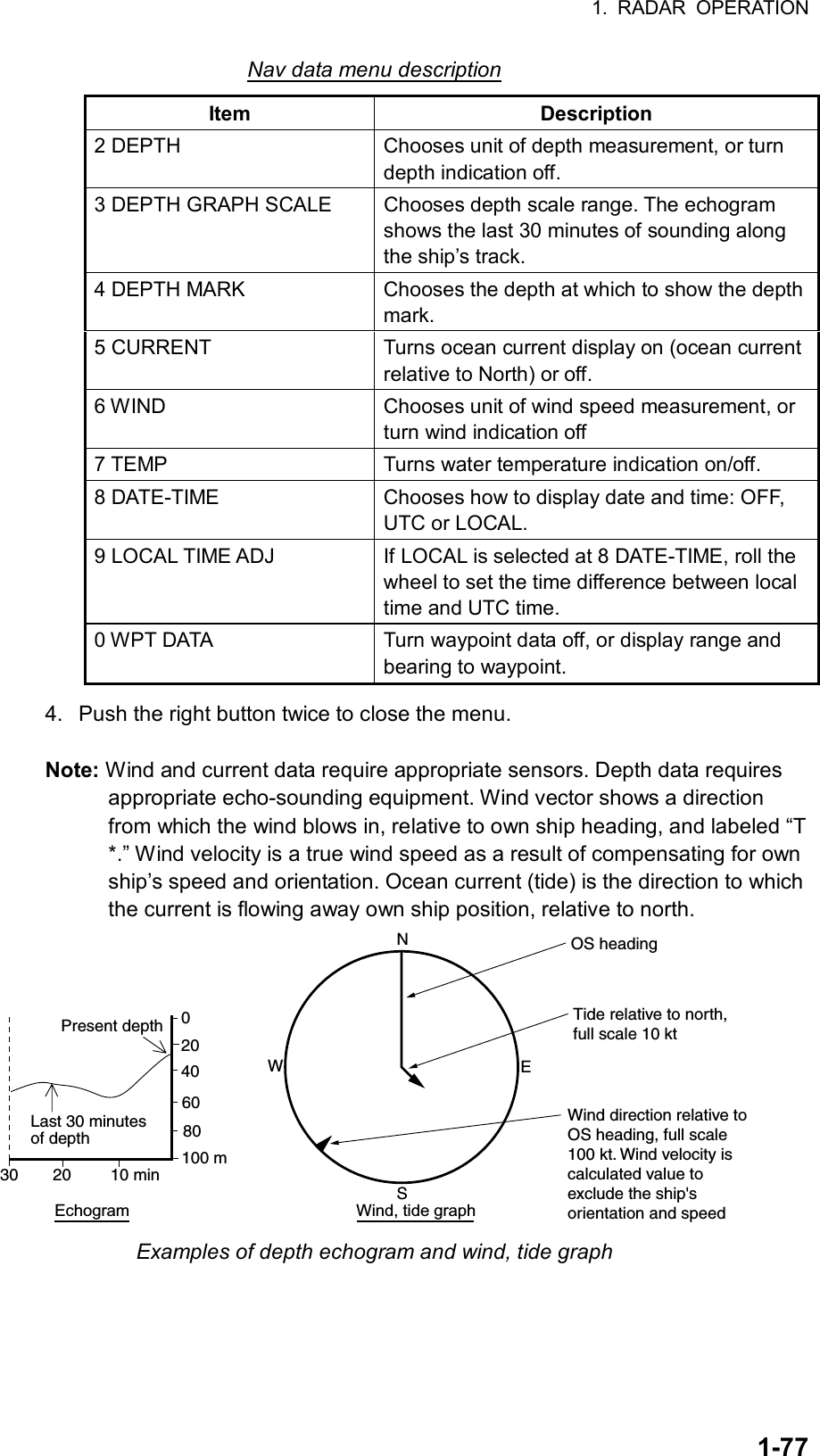
![1. RADAR OPERATION 1-76 [NAV DATA] 1 BACK 2 DEPTH OFF/m/ft 3 DEPTH GRAPH SCALE 10/20/50/ 100/200/500 4 DEPTH MARK 0000 5 CURRENT OFF/ON 6 WIND OFF/m/s/KT 7 TEMP OFF/ON 8 DATE-TIME OFF/UTC/LOCAL 9 LOCAL TIME ADJ +00:00 0 WPT DATA OFF/REL/TRUE 1.40 Setting Up Nav Data Wind, depth, ocean current, water temperature, date and time and waypoint data may be set up as follows: 1. Roll the trackball to choose the MENU box at the right side of the screen and then push the left button. 2. Roll the wheel to choose 7 NAV DATA and then push left button to open the NAV DATA menu. NAV DATA menu 3. Choose appropriate options referring to the table on the next page for details.](https://usermanual.wiki/Furuno-USA/9ZWRTR078/User-Guide-356443-Page-94.png)
![1. RADAR OPERATION 1-78 [CUSTOMIZE•TEST MENU] 1 BACK 2 [DATA BOX] 3 [F1] 4 [F2] 5 [F3] 6 [F4] 7 [OPERATION] 8 [TEST] [DATA BOX MENU] 1 BACK 2 3 NAV DATA OFF/ON 4 ZOOM OFF/2TIMES/3TIMES 5 ZOOM DISPLAY REL/STAB/ACQ 6. TARGET DATA 1BOX/2BOX/3BOX/ LARGE 1.41 Text Window Setup The text window, displayed at the right 1/4 of the screen, mainly shows nav data, zoomed target, and ARPA target data. You can set up this window as follows: 1. Roll the trackball to choose the MENU box at the right side of the screen and then push the left button. 2. Roll the wheel to choose 9 [CUSTOMIZE•TEST] and then push the wheel or the left button. CUSTOMIZE•TEST menu 3. Roll the wheel to choose 2 [DATA BOX] and then push the wheel or the left button. DATA BOX menu 4. Roll the wheel to choose 3 NAV DATA and then push the wheel or the left button. 5. Roll the wheel to choose OFF or ON as appropriate and then push the wheel or the left button. 6. Roll the wheel to choose 4 ZOOM and then push the wheel or the left button. 7. Roll the wheel to choose OFF or zoom magnification factor (2TIMES or 3 TIMES) and then push the wheel or the left button. 8. If you chose a zoom factor at step 7, go to step 9. Otherwise, go to step 11. 9. Roll the wheel to choose 5 ZOOM DISPLAY and then push the wheel or the left button.](https://usermanual.wiki/Furuno-USA/9ZWRTR078/User-Guide-356443-Page-96.png)
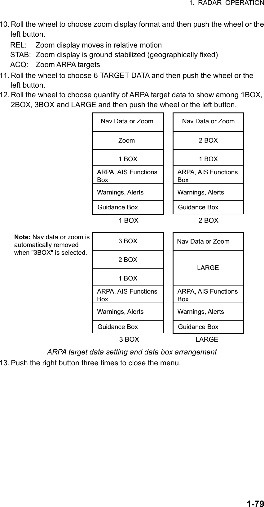
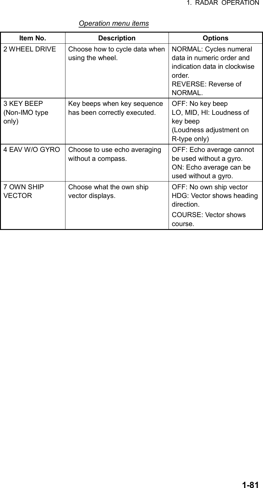
![1. RADAR OPERATION 1-80 [CUSTOMIZE•TEST MENU] 1 BACK 2 [DATA BOX] 3 [F1] 4 [F2] 5 [F3] 6 [F4] 7 [OPERATION] 8 [TEST] [OPERATION MENU] 1 BACK 2 WHEEL DRIVE NORMAL/REVERSE 3 KEY BEEP OFF/LO/MID/HI 4. EAV W/O GYRO OFF/ON 5 6 7 OWN SHIP VECTOR OFF/HDG/COURSE 1.42 Customizing Operation Several operation items may be customized to suit your needs. 1. Roll the trackball to choose the MENU box at the right side of the screen and then push the left button. 2. Roll the wheel to choose 9 [CUSTOMIZE•TEST] and then push the wheel or the left button to open the CUSTOMIZE•TEST menu. CUSTOMIZE•TEST menu 3. Roll the wheel to choose 7 [OPERATION] and then push the wheel or the left button. OPERATION menu 4. Set each item as appropriate, referring to the table on the next page for details. 5. Push the right button to close the menu.](https://usermanual.wiki/Furuno-USA/9ZWRTR078/User-Guide-356443-Page-98.png)
![1. RADAR OPERATION 1-82 1.43 Alarms When error is detected, the appropriate alarm indication appears (in red) and the audible alarm sounds. Silence the audible alarm with the [ALARM ACK] key or choose the ALARM ACK box and then push the left button. The error indication remains on the display until the reason for the alarm is removed. 1.43.1 Alarm description Alarm description Warning Audible alarm Visual alarm To quit alarm status GYRO failure 2 beeps HDG indication reads “***.*” and the message SET HDG appears at the lower-left corner of the screen. GYRO in red. Display is automatically switched to head-up mode within 1 min. Match the on-screen HDG readout with the actual compass reading, if necessary. Guard alarm Beeps Target flashes. Press the [ALARM ACK] key or click the ALARM ACK box with the left button. WATCH alarm Beeps WATCH 0:00 (WATCH box turns red and time count freezes at 0:00). Press the [ALARM ACK] key or click the WATCH box with the left button. The WATCH box is displayed in normal video and the timer is reset. Own ship lat/lon Cursor lat/lon None “***.*” In own ship position field “***.*” In cursor position field Make sure that own ship position data is fed from external radionav equipment.System failure None Message BRG SIG MISSING appears at screen bottom. No radar echoes. SYSTEM FAIL in red at the lower left of the display during test. Make sure the antenna is turned on Incorrect keystroke Double beep tone (R-type) None Correct keystroke is responded by a single beep provided that KEY BEEP ON is selected in the OPERATION menu. Log failure 2 beeps LOG **.* and LOG appear in red, if no log signal is input for 30 s while the ship speed has been more than 5.0 kt. If the SDME has failed, use the Manual Speed mode or other appropriate sensor.](https://usermanual.wiki/Furuno-USA/9ZWRTR078/User-Guide-356443-Page-100.png)
![1. RADAR OPERATION 1-83Alarm description (con’t from previous page) Warning Audible alarm Visual alarm To quit alarm status EPFS failure Continuous beep EPFS in red (EPFS: electronic position-fixing system) in the warning and indication cell. The indication also appears when the GPS mode is switched between GPS and DGPS. To silence the beep and erase the message, press the [ALARM ACK] key or click the ALARM ACK box with the left button. Message cannot be erased if position signal is missing; it is automatically erased when signal is restored. SOG indication none The SOG (Speed Made Good) indication turns red at the top data cell when SOG option is selected on the menu and the associated SDME (Speed and Distance Measuring Equipment = Speed log) fails to detect a bottom tracking speed, resulting in the “Speed through the water” (STW) mode automatically. COLLISION Continuous beep COLLISION comes on when ARPA-tracked target is on collision course. Take evasive action or terminate tracking of target. Then, the visual indication goes off. TRUE VECTOR indication None The TRUE VECTOR indication turns red when the TRUE Vector is selected in the RM mode, and returns to the normal text color in the North-up TM mode. Guard Zone alarm Continuous beep The label GZ appears in red if a target enters to the guard zone. Target is masked by a flashing inverted triangle. Press the [ALARM ACK] key or click the ALARM ACK box with the left button to acknowledge it. GZ OUT alarm None If the range scale has been reduced to make one of GZs positions more than 1.5 times of the range scale, the label GZ OUT appears in red. Change the range scale of GZ.](https://usermanual.wiki/Furuno-USA/9ZWRTR078/User-Guide-356443-Page-101.png)
![1. RADAR OPERATION 1-84 [ALARM MENU] 1 BACK 2 GUARD ALARM MODE IN/OUT 3 GUARD ALARM LEVEL 1/2/3/4 4 WATCH ALARM OFF/6M/10M/ 12M/15/20M 5 ALARM SOUND LEVEL LOW/MID/HIGH 6 [ALARM OUT1] 7 [ALARM OUT2] 8 [ALARM OUT3] [ALARM OUT1] 1 BACK 2 GUARD ALARM/ WATCH ALARM/ GUARD ZONE/ LOST TARGET/ CPA LIMIT/ AUTO ACQ TARGET FULL/ MAN ACQ TARGET FULL/ ARPA SYSTEM ERROR/ AZIMUTH/ HEAD LINE/ TRIGGER/VIDEO/ GYRO/LOG/EPFS/ XTE/ ARRIVAL WPT/ DEPTH 1.43.2 Outputting alarm signal Four ports are provided from which to output alarm signals to external equipment. Choose the port and alarm signals to output as follows: 1. Roll the trackball to choose the MENU box and then push the left button. 2. Roll the wheel to choose 3 ALARM and then push the wheel or the left button. ALARM menu 3. Roll the wheel to choose appropriate “ALARM OUT” item, and then push the wheel or the left button. ALARM OUT1 menu 4. Roll the wheel to choose an alarm to output and then push the wheel or the left button. The alarm chosen is underlined. 5. Repeat step 5 to choose other alarms to output. 6. Push the right button three times to close the menu.](https://usermanual.wiki/Furuno-USA/9ZWRTR078/User-Guide-356443-Page-102.png)
![1. RADAR OPERATION 1-85 [ANT INFORMATION] ANT NO 1 BAND : X-BAND MODEL : 12 POS : FORE ANT NO 2 BAND : X-BAND MODEL : 12 POS : FORE 1.44 Choosing the Antenna, Displaying Antenna Information 1.44.1 Choosing the antenna For the ship which carries multiple antennas you may choose the antenna to use as follows: 1. Roll the trackball to place the arrow in the ANTENNA box at the left side of the screen. ANT1 X-BAND ANTENNA box 2. Push the left button to choose the antenna to use. 1.44.2 Displaying antenna information You may display information about the antenna(s) installed. This feature is not available when the interswitch is in use. 1. Roll the trackball to place the arrow in the ANTENNA box at the left side of the screen. 2. Push the left button to choose the antenna for which you want to find information. (You cannot choose an antenna which does not exist or one which is not powered.) 3. Push the right button to show the antenna information display. ANT NO.: Antenna number. BAND: X-band or S-band MODEL: Antenna output power (in kW). For example, “12” is 12 kW. POS: Antenna position ANTENNA INFORMATION display 4. Push the right button to close the antenna information display.](https://usermanual.wiki/Furuno-USA/9ZWRTR078/User-Guide-356443-Page-103.png)
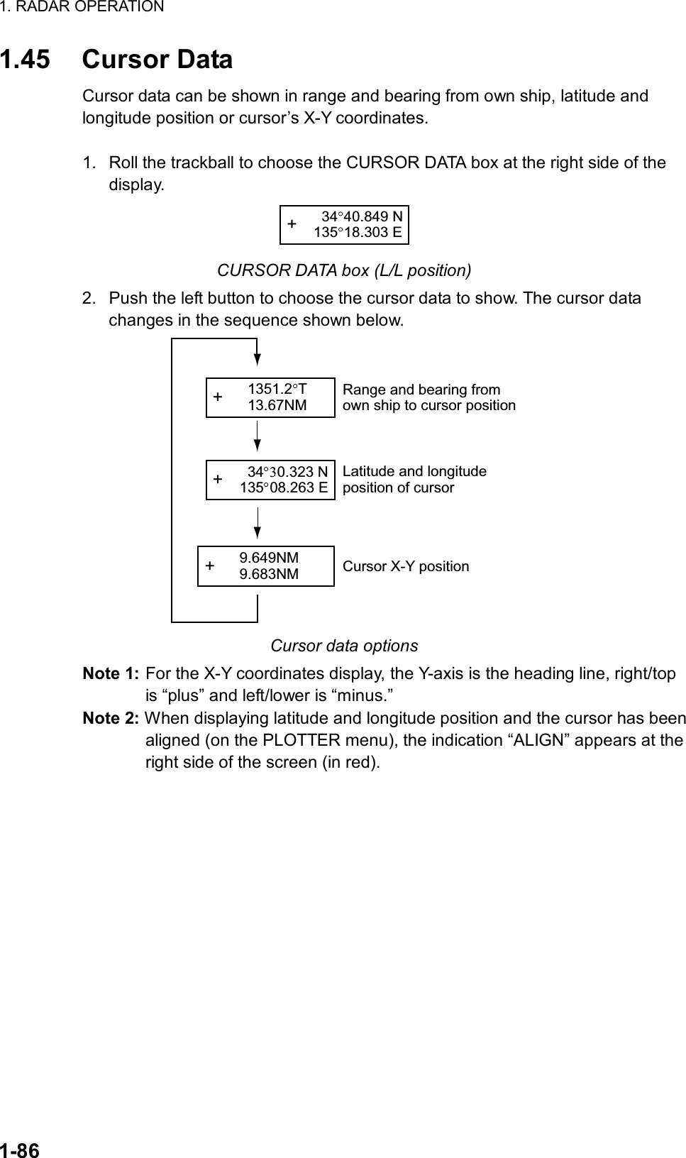
![1. RADAR OPERATION 1-87 [ECHO MENU] 1 BACK 2 2ND ECHO REJ OFF/ON 3 TUNE INITIALIZE 4 PM OFF/ON 5 SART OFF/ON 6 WIPER OFF/1/2 1.46 Performance Monitor A performance monitor is required for a radar installed on vessels of 300 GT and upward engaged in international voyages. For X-band radars, the FURUNO PM-31 satisfies the requirement covering 9410 ± 50 MHz. The following describes how to use these performance monitors. The performance monitor is an independent unit, namely, it is not interconnected with any unit of the radar system except for the 100 VAC power cable. In some radars the power cable is not routed via the power switch or other control of the radar and the monitor is operated as completely a separate device. 1.46.1 Activating, deactivating the performance monitor 2. Roll the trackball to choose the MENU box and then push the left button. 3. Roll the wheel to choose 1 ECHO and then push the wheel or the left button. ECHO menu 4. Roll the wheel to choose 4 PM and then push the wheel or the left button. 5. Roll the wheel to choose OFF or ON as appropriate and then push the wheel or the left button. 6. Push the right button twice to close the menu. 1.46.2 Checking radar performance 1. Set the interswitch to the “straight mode.” 2. The radar is automatically set up as follows: Range: 24 nm Pulselength: Long Shadow Sector: Off STC: Off RAIN: Off Echo Stretch: Off Echo Average: Off Video Contrast: A Tune: Auto 3. Turn on the performance monitor referring to paragraph 1.47.1. 4. After observing the results turn off the performance monitor.](https://usermanual.wiki/Furuno-USA/9ZWRTR078/User-Guide-356443-Page-105.png)
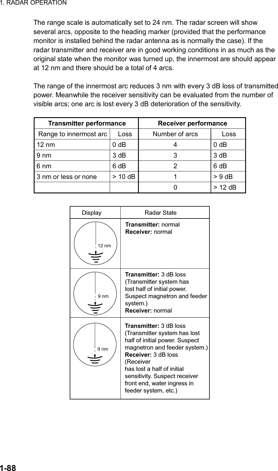
![1. RADAR OPERATION 1-89 [ECHO MENU] 1 BACK 2 2ND ECHO REJ OFF/ON 3 TUNE INITIALIZE 4 PM OFF/ON 5 SART OFF/ON 6 WIPER OFF/1/2 1.47 Wiper The wiper feature lets you display both targets processed by echo averaging and those missed by echo averaging, for example, high-speed craft. This feature is useful for discriminating targets from sea clutter and discerning high-speed targets. Echo averaging must be turned on to use the wiper feature. To activate the wiper feature, do the following: 1. Roll the trackball to choose the MENU box and then push the left button. 2. Roll the wheel to choose 1 ECHO and then push the wheel or the left button. ECHO menu 3. Roll the wheel to choose 6 WIPER and then push the wheel or the left button. 4. Roll the wheel to choose OFF, 1 or 2 as appropriate and then push the wheel or the left button. 5. Push the right button twice to close the menu.](https://usermanual.wiki/Furuno-USA/9ZWRTR078/User-Guide-356443-Page-107.png)
![1. RADAR OPERATION 1-90 [MARK MENU] 1 ORIGIN MARK STAB GND/SEA 2 ORIGIN MARK(No.)/ ORIGIN MARK(SYMBOL)/ MAP MARK/ WP 1~50/ WP 51~100/ WP 101~150/ WP 151~200/ OWN SHIP SHAPE 9 MAP DISPLAY OFF/ON 0 MAP MARK COLOR* RED/GRN/BLU/YEL/ CYA/MAG/WHT 1.48 Own Ship Marker Own ship marker ( ) may be inscribed on the screen as below. You may enter ten such markers. Each own ship marker is shown with a number. 1. Roll the trackball to choose the MARK box at the left side of the screen. The guidance box now reads “MARK SELECT / MARK MENU.” MARK Mark type lastselected, marknumber> +162.5 T 11.7NMBearing and range from own ship to own ship mark1 Mark box 2. Push the right button to open the MARK menu. MARK menu 3. Roll the wheel to choose “2” and then push the wheel or the left button. 4. Roll the wheel to choose OWN SHIP SHAPE and then push the wheel or the left button. 5. Push the right button to close the menu. 6. Push the left button. The cursor jumps to the screen center and the guidance box now reads “MARK / EXIT.” 7. Push the left button to inscribe the own ship marker. • To enter another own ship marker with a different number, place the cursor in the MARK box, roll the wheel to choose marker number, press the left button twice, then push the left button. (OWN SHIP SHAPE should be preselected on the MARK menu.) • To quit entering own ship markers, push the right button when the guidance box reads “MARK / EXIT.” * Not available on IMO radar.](https://usermanual.wiki/Furuno-USA/9ZWRTR078/User-Guide-356443-Page-108.png)
![1. RADAR OPERATION 1-911.49 Color and Brilliance Sets This radar provides four sets of color and brilliance sets to match any ambient lighting condition. The default colors are as shown in the table below. The default brilliance setting for any item is “50%”. BRILL1 BRILL2 BRILL3 BRILL4 Echo Yellow Yellow Yellow Yellow Inside Display, Outside Display Black, Black Black, Black Black, Black Black, Blue Menu Yellow Yellow Yellow Yellow Characters Green Red Green White Bearing Scale Blue Red White Green 1.49.1 Choosing color and brilliance set 1. Roll the trackball to choose the BRILL box at the left side of the screen. 2. Roll the wheel to choose color and brilliance set from among BRILL1 – BRILL4. 3. Push the wheel to finish. 1.49.2 Presetting color and brilliance set 1. Roll the trackball to choose the BRILL box at the left side of the screen. 2. Push the right button to open the BRILL menu. [BRILL1 MENU (1/2)]1 ECHO COLOR YEL/GRN/ WHT/COLOR*2 BKGD COLOR BLK-GRN/ BLK-RED/ BLU-CIR/ BLU/BRT-BLU3 PANEL DIMMER4 CHARACTER5 CURSOR6 ECHO7 TRAIL8 HL9 RING0 NEXT * Not available on IMO radar. BRILL menu 3. Roll the wheel to choose 1 ECHO COLOR and then push the wheel or the left button. 4. Roll the wheel to choose echo color desired and then push the wheel or the left button. “COLOR,” available on the R-type radar, displays echoes in colors of red, yellow and green, corresponding to signal levels of strong, medium and weak.](https://usermanual.wiki/Furuno-USA/9ZWRTR078/User-Guide-356443-Page-109.png)
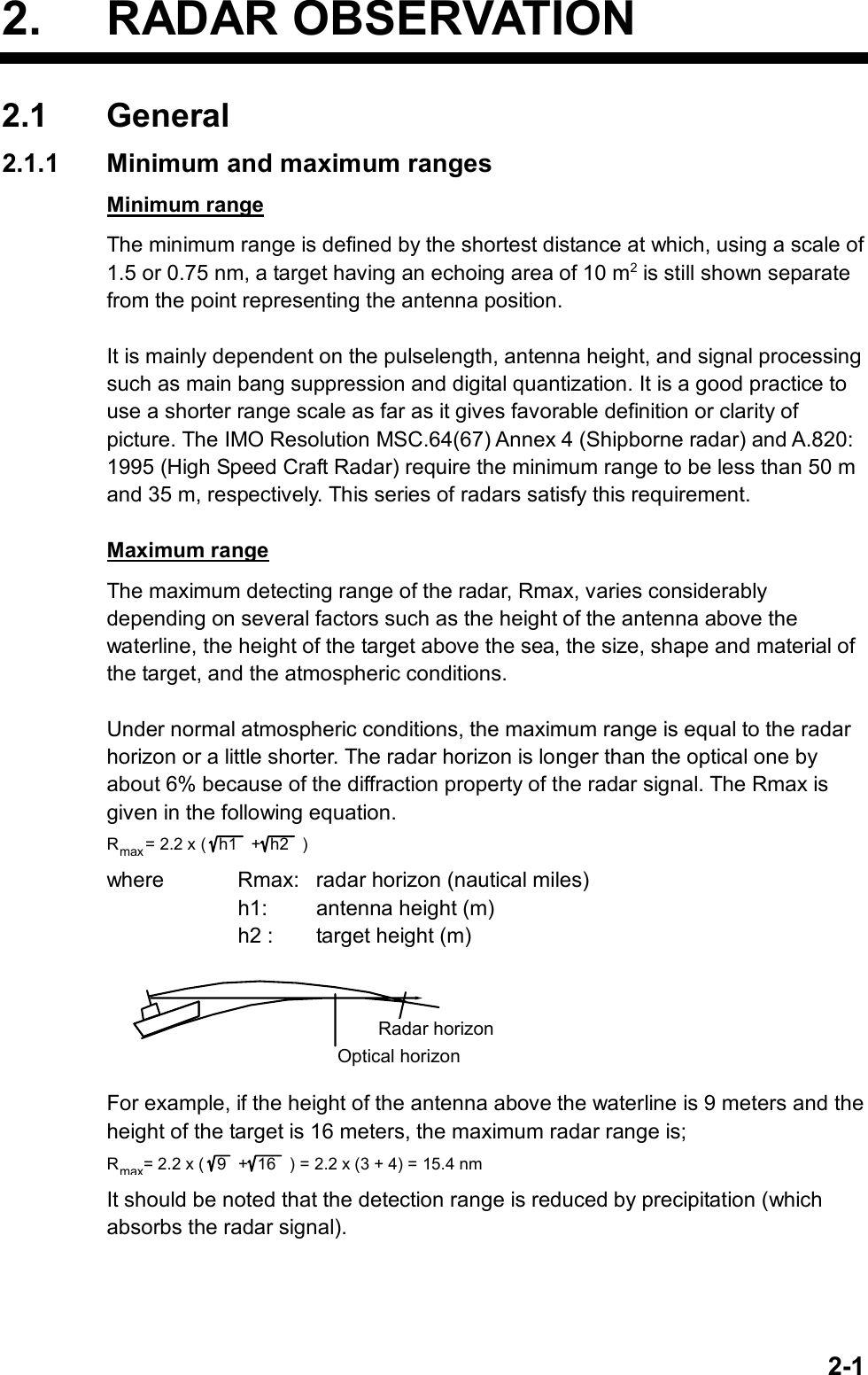
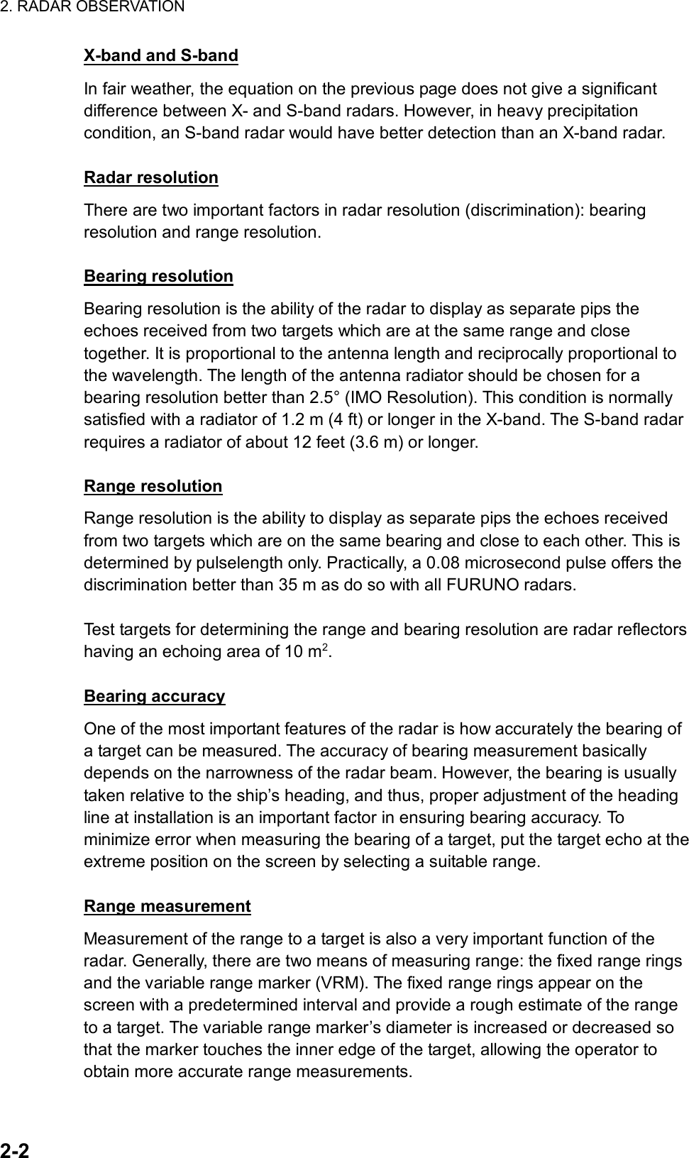
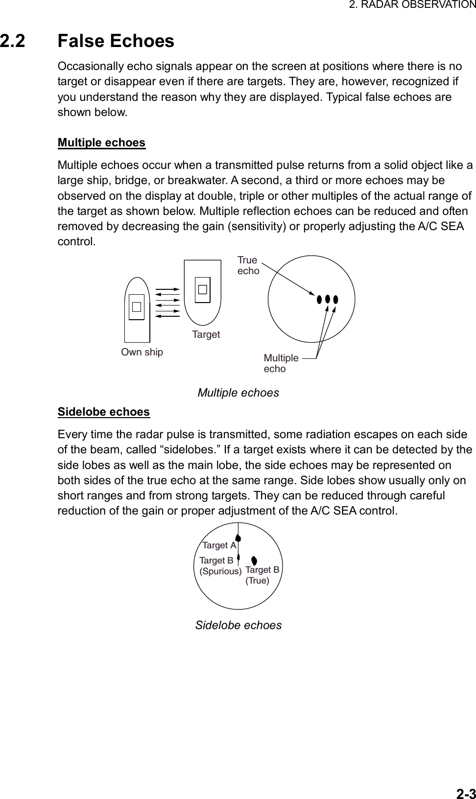
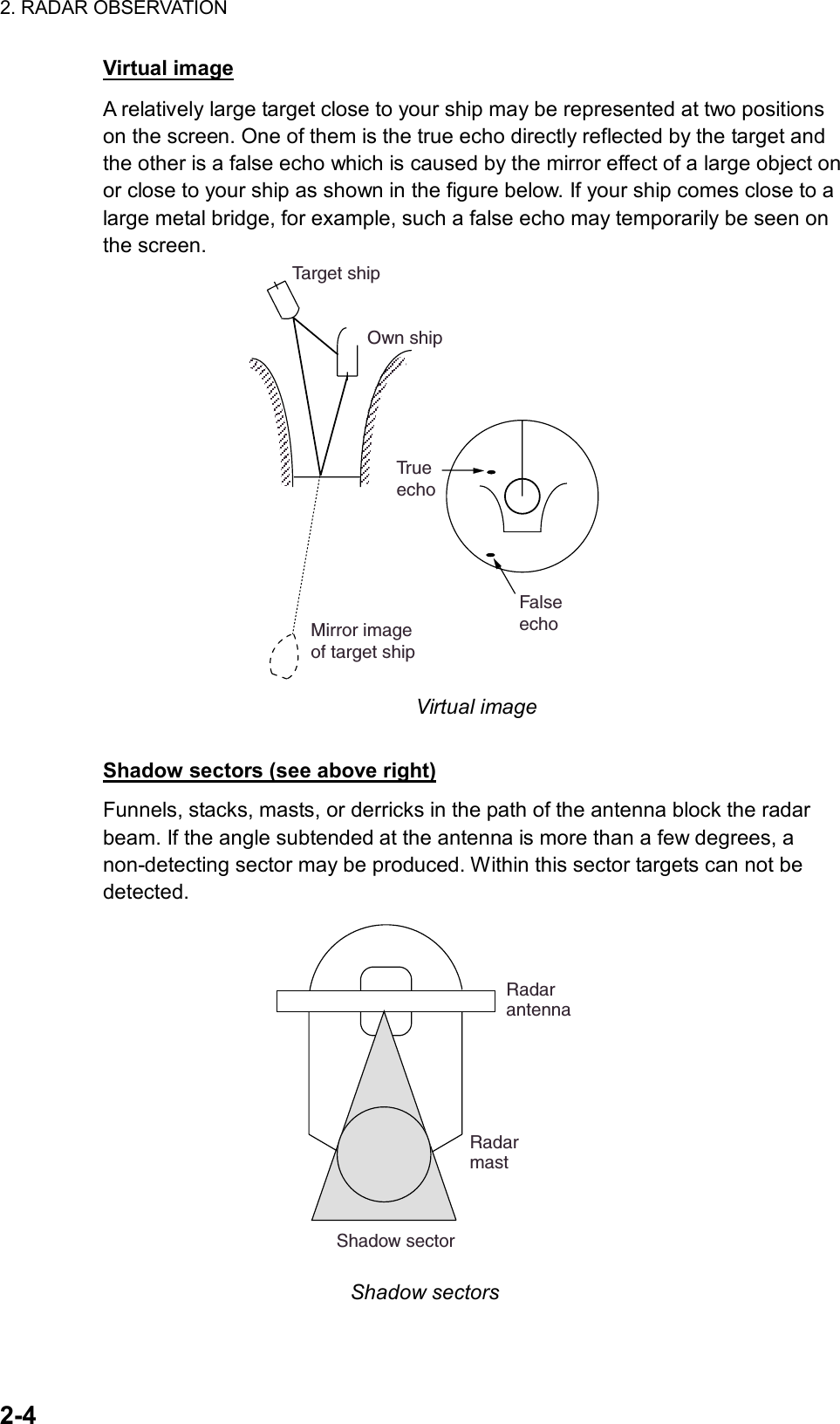
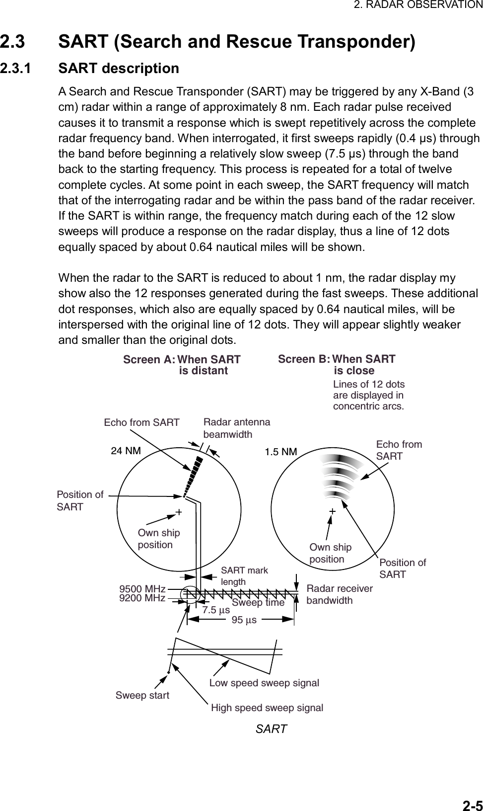
![2. RADAR OBSERVATION 2-6 [ECHO MENU] 1 BACK 2 2ND ECHO REJ OFF/ON 3 TUNE INITIALIZE 4 PM OFF/ON 5 SART OFF/ON 6 WIPER OFF/1/22.3.2 Showing SART marks on the radar display This radar is equipped with a feature which optimally sets up the radar for SART detection. This feature automatically detunes the radar receiver out of its best tuning condition. This erases or weakens all normal radar echoes, but the SART marks are not erased because the SART response signal scans over all frequencies in the 9 GHz band. When the radar approaches the SART in operation, the SART marks will enlarge to large arcs, blurring a large part of the screen. To set up for SART detection do the following: 1. Roll the trackball to choose the MENU box and then push the wheel or the left button. 2. Roll the wheel to choose 1 ECHO and then push the wheel or the left button. Echo menu 3. Roll the wheel to choose 5 SART and then push the wheel or the left button. 4. Roll the wheel to choose ON and then push the wheel or the left button. With SART turned on radar functions are set as follows: Range: 12 nm Pulselength: Long Echo Stretch: Off Noise Rejector: Off Echo Averaging: Off Interference Rejector: Off Performance Monitor: Off A/C RAIN: Off 5. Push the right button twice to close the menu. Be sure to turn off the SART feature when SART detection is no longer your objective.](https://usermanual.wiki/Furuno-USA/9ZWRTR078/User-Guide-356443-Page-116.png)
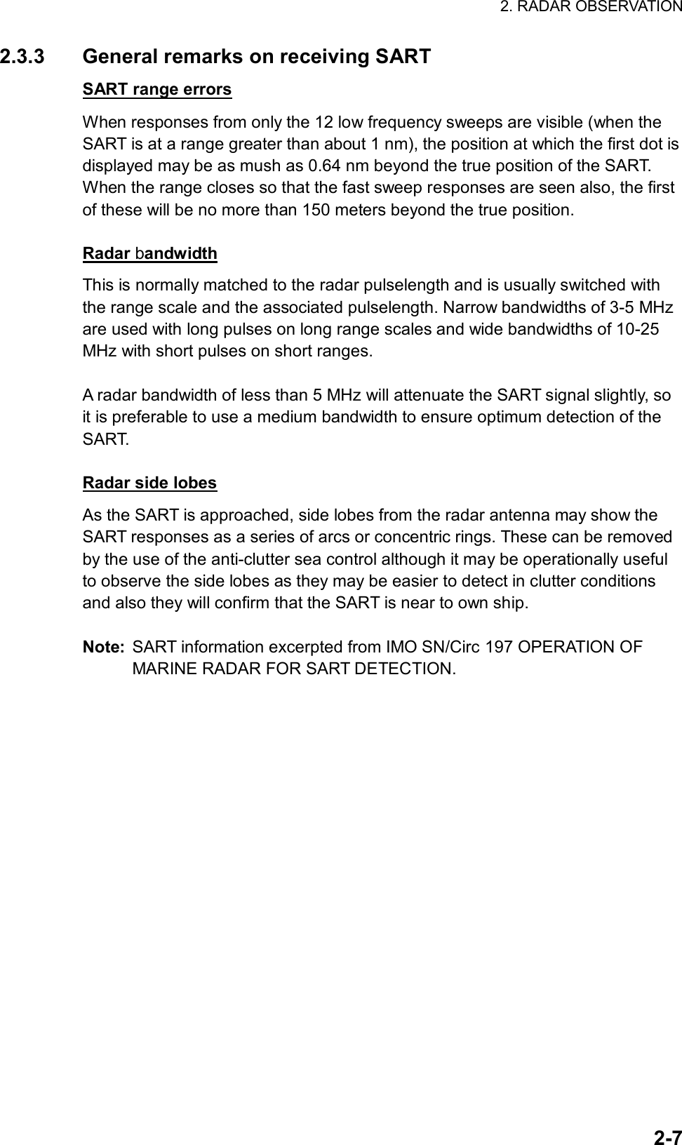
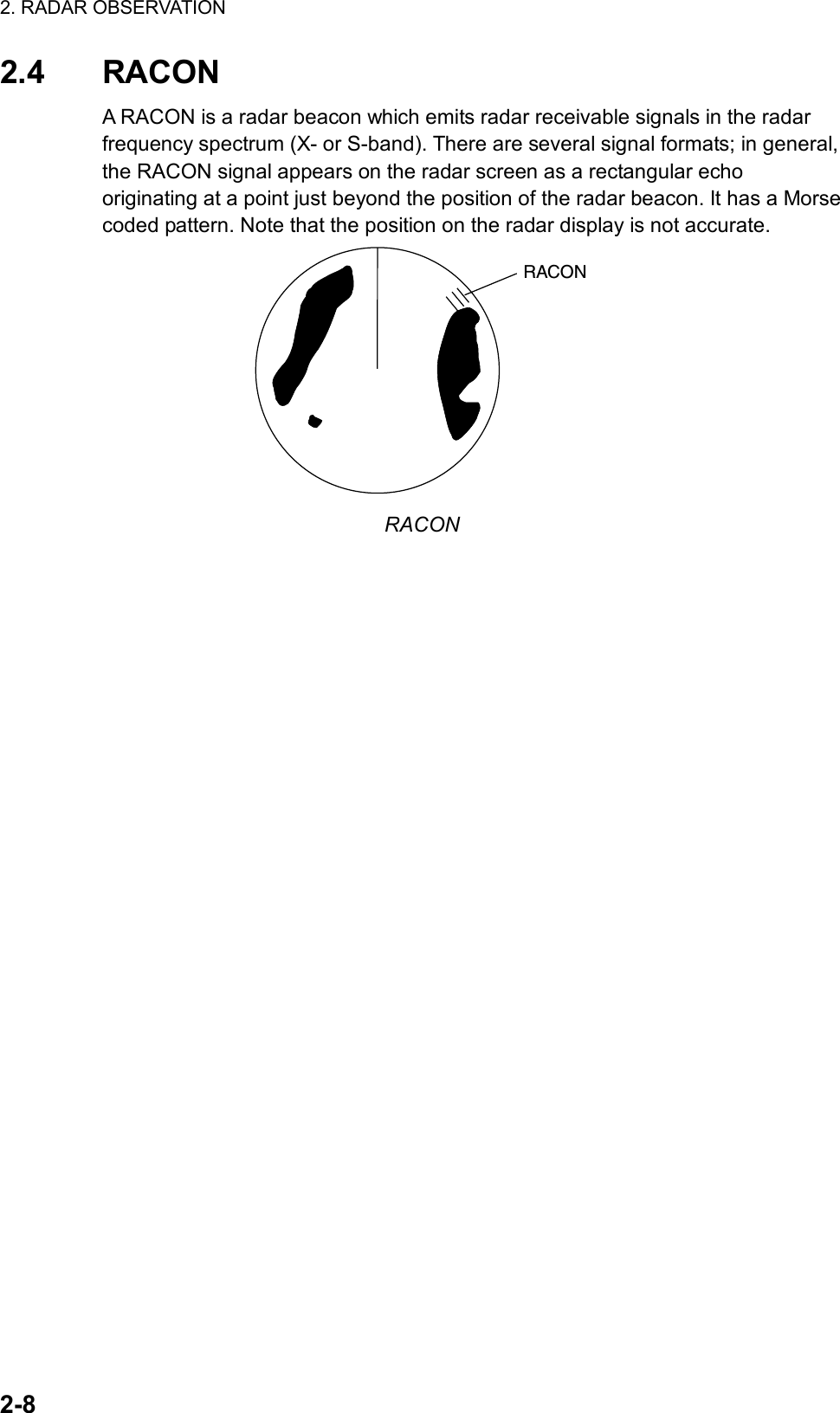
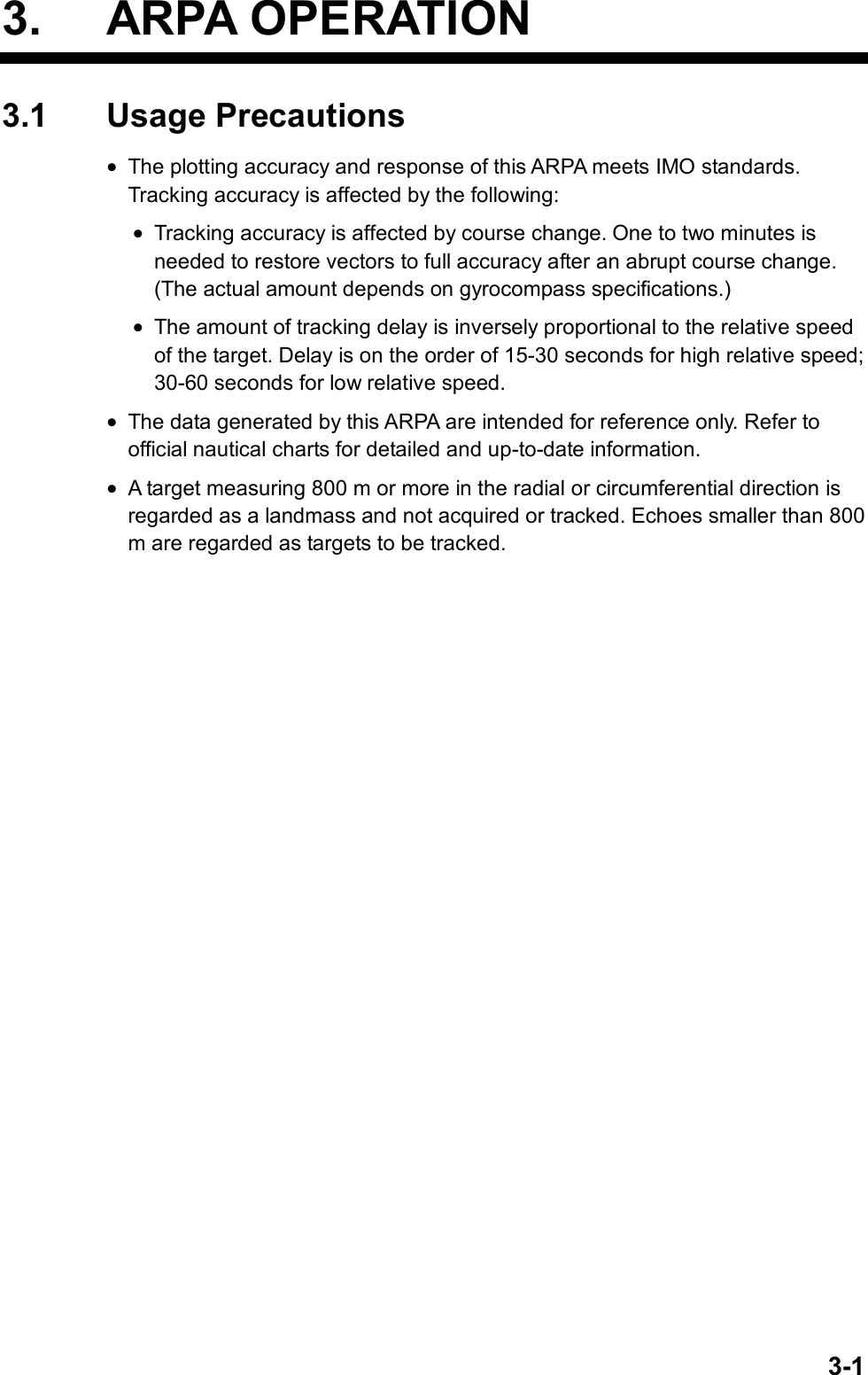
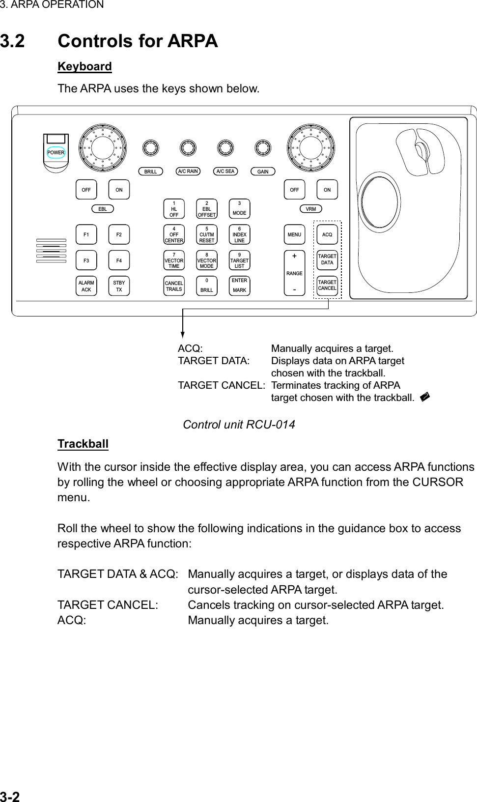
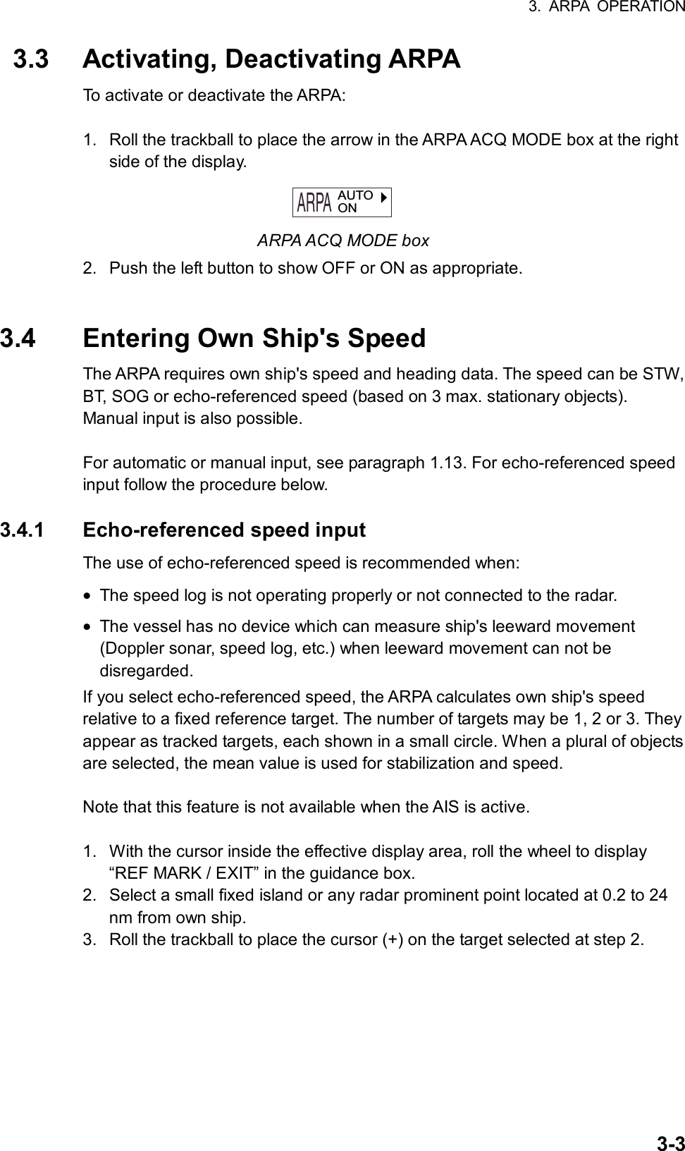
![3. ARPA OPERATION 3-4 4. Push the left button to enter the reference mark. (The mark may also be entered by pressing the [ENTER MARK] key on the full keyboard.) The reference target mark (see below) appears at the cursor position and the own ship position data label changes from “LOG,” “NAV” or “MANUAL” to “REF.” Note that it takes 60 scans or approximately 1 min before a new speed is displayed. If tracking has failed for a reference target, the target is marked with a lost target mark (symbol formed with two triangles). changes to in 60 seconds. R1 R1 Reference target 5. Repeat steps 2-4 to continue entering reference marks. Three may be entered. Notes on speed input by reference target • When the reference target is lost or goes out of the acquisition range, the reference target mark blinks and the speed reads “**.*.” Select a different reference target in this case. • When all targets are deleted, the reference target mark is also deleted and the target-based speed becomes invalid. The speed is indicated as KTBT where BT means Bottom Track (speed over ground). • Reference targets may be marked with a vector. This can be done with 3 REF TARGET VECTOR on the ARPA TARGET menu. Canceling echo-referenced speed input Open the SPD menu, referring to paragraph 1.13, and set 1 SHIP SPEED to LOG, NAV or MANUAL as appropriate.](https://usermanual.wiki/Furuno-USA/9ZWRTR078/User-Guide-356443-Page-122.png)
![3. ARPA OPERATION 3-5 [ARPA TARGET MENU] 1 ARPA SELECT MANUAL100/ AUTO25/ AUTO50/ AUTO75/ AUTO100 2 ALL CANCEL 3 REF TARGET VECTOR OFF/ON 3.5 Automatic Acquisition The ARPA can acquire a maximum of 100 targets, the number of automatically and manually acquired targets determined by the ARPA TGT menu setting. ARPA TGT menu setting and target acquisition condition Menu Setting Acquisition condition MANUAL100 100 targets manually AUTO25 25 targets automatically, 75 targets manually AUTO50 50 targets automatically, 50 targets manually AUTO75 75 targets automatically, 25 targets manually AUTO100 100 targets automatically A target just acquired automatically is marked with a broken square and a vector appears within 20 scans of the antenna to indicate the target's motion trend. Within 60 scans, the initial tracking stage is finished and the target becomes ready for stable tracking. At this point, the broken square mark changes to a solid circle. (Targets automatically acquired are distinguished from those acquired manually. The targets which are acquired manually are displayed by bold symbol.) 3.5.1 Enabling auto acquisition 1. Roll the trackball to place the arrow in the ARPA ACQ MODE box at the right side of the screen and then push the right button to show the ARPA TARGET menu. ARPA TARGET menu 2. Roll the wheel to choose 1 ARPA SELECT and then push the wheel or the left button. 3. Roll the wheel to choose automatic acquisition condition desired, referring to the table above for details, and then push the wheel or the left button. 4. Push the right button to close the menu. Note 1: The ARPA ACQ MODE box shows AUTO or AUTO MAN depending on the automatic acquisition condition selected. Note 2: When the menu-set number of automatically acquired targets is reached, the message “TARGET-FULL(AUTO)” is displayed at the right-hand side of screen.](https://usermanual.wiki/Furuno-USA/9ZWRTR078/User-Guide-356443-Page-123.png)
![3. ARPA OPERATION 3-6 [ARPA TARGET MENU] 1 ARPA SELECT MANUAL100/ AUTO25/ AUTO50/ AUTO75/ AUTO100 2 ALL CANCEL 3 REF TARGET VECTOR OFF/ON 3.5.2 Terminating tracking of targets (including reference targets) When the ARPA has acquired the menu-set number of targets automatically, the message “TARGET-FULL(AUTO)” appears at the right side of the screen and no more auto acquisition occurs unless targets are lost. Should this happen, cancel tracking of less important targets or perform manual acquisition. Canceling individual targets By keyboard: 1. Roll the trackball to place the cursor (+) on the ARPA or reference target to cancel tracking. 2. Press the [TARGET CANCEL] key. By trackball: 1. With the cursor inside the effective display area, roll the wheel to show TARGET CANCEL / EXIT in the guidance box. 2. Roll the trackball to place the cursor on the ARPA target or reference target to cancel tracking. 3. Push the left button or the wheel to cancel tracking on the target selected. 4. To finish, push the right button. Canceling tracking on all targets 1. Roll the trackball to choose the ARPA ACQ MODE box at the right side of the screen and then push the right button. ARPA TARGET menu 2. Use the wheel to choose 2 ALL CANCEL. 3. Push the wheel or the left button to cancel tracking on all ARPA targets.](https://usermanual.wiki/Furuno-USA/9ZWRTR078/User-Guide-356443-Page-124.png)
![3. ARPA OPERATION 3-7 [ARPA TARGET MENU] 1 ARPA SELECT MANUAL100/ AUTO25/ AUTO50/ AUTO75/ AUTO100 2 ALL CANCEL 3 REF TARGET VECTOR3.6 Manual Acquisition Maximum 100 targets may be acquired manually depending on the acquisition condition set on the ARPA TGT menu. 3.6.1 Setting manual acquisition conditions 1. Roll the trackball to place the arrow in the ARPA ACQ MODE box at the right side of the screen and then push the right button to show the ARPA TARGET menu. ARPA TARGET menu 2. Roll the wheel to choose 1 ARPA SELECT and then push the wheel. 3. Roll the wheel to choose MANUAL100, AUTO25, AUTO50 or AUTO75 as appropriate and then push the wheel or the left button. For details see the table on page 3-5. 4. Push the right button to close the menu. 3.6.2 Manually acquiring a target By keyboard 1. Roll the trackball to place the cursor on the target you want to acquire. 2. Press the [ACQ] key. By trackball 1. With the cursor inside the effective display area, roll the wheel to show “TARGET DATA & ACQ” or “ACQ” in the guidance box. 2. Roll the trackball to place the cursor on the target you want to acquire. 3. Push the left button to acquire the target.](https://usermanual.wiki/Furuno-USA/9ZWRTR078/User-Guide-356443-Page-125.png)
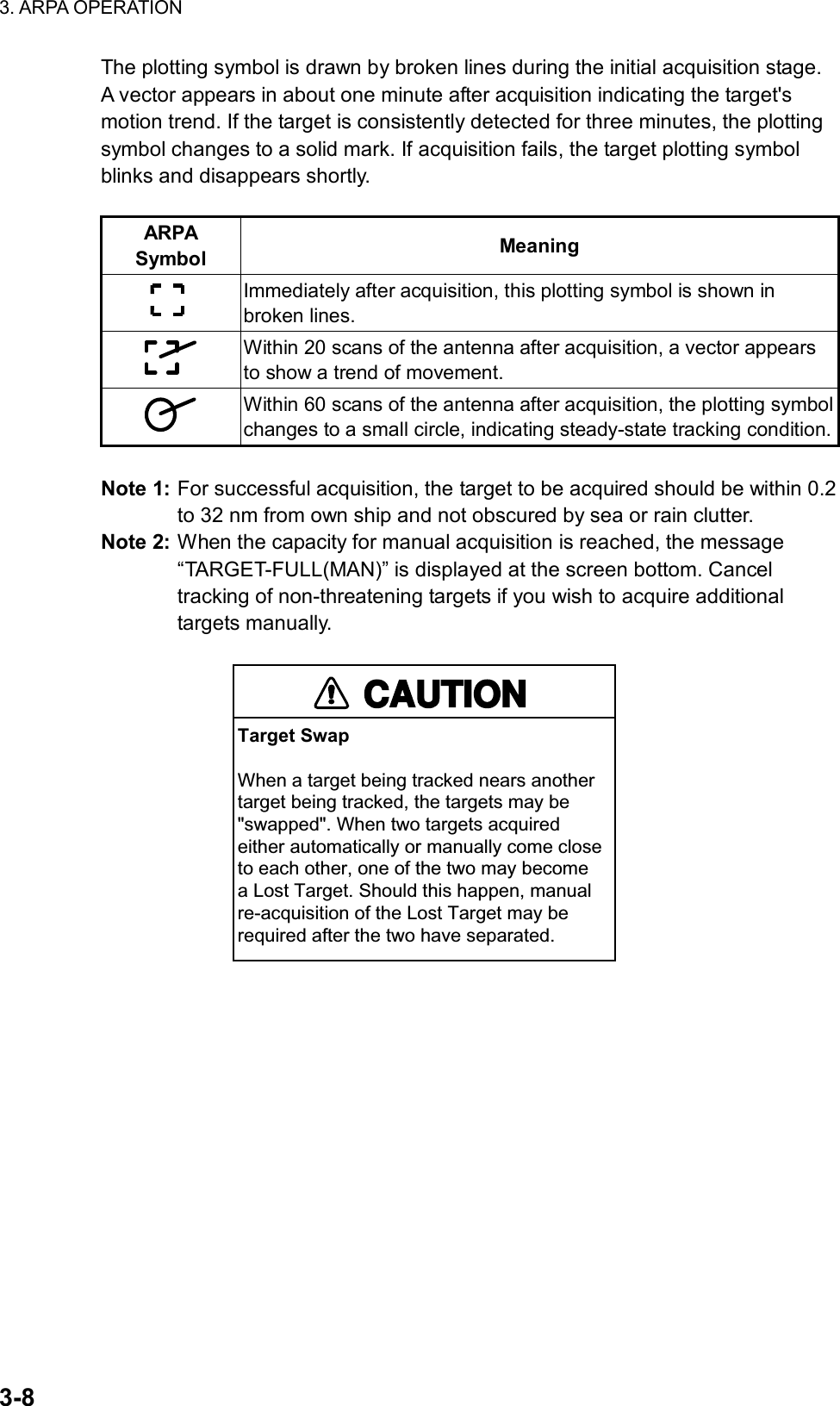
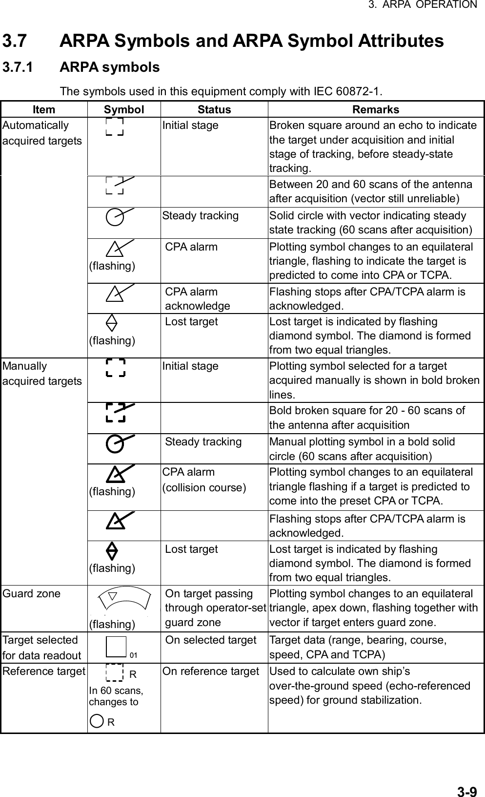
![3. ARPA OPERATION 3-10 Other ARPA symbols Item Symbol Status Remarks Trial maneuver T (flashing) Bottom center Appears during execution of a trial maneuver. Performance test XX (flashing) Bottom center Appears during performance test. 3.7.2 ARPA symbol brilliance 1. Roll the trackball to choose the BRILL box at the left side of the screen and then push the right button. 2. Roll the wheel to choose 0 NEXT and then push the wheel or the left button. [BRILL1 MENU (2/2)]1 BACK2 BEARING CURSOR3 EBL4 VRM5 INDEX LINE6 ARPA SYMBOL7 AIS SYMBOL8 L/L GRID9 MARK0 CHART BRILL menu, page 2 3. Roll the wheel to choose 6 ARPA SYMBOL and then push the wheel or the left button. 4. Roll the wheel to adjust brilliance. 5. Push the right button twice to close the menu.](https://usermanual.wiki/Furuno-USA/9ZWRTR078/User-Guide-356443-Page-128.png)
![3. ARPA OPERATION 3-11 [ARPA•AIS MENU] 1 BACK 2 GUARD ZONE STAB STAB HDG/STAB NORTH 3 GUARD POLYGON OFF/STAB GND/ STAB HDG/STAB NORTH 4 [TRIAL MANEUVER] 5 [ARPA SYMBOL] 6 [AIS SYMBOL] 7 [FUSION] 8 AIS FUNCTION OFF/ON [ARPA SYMBOL] 1 BACK 2 ARPA SYMBOL COLOR RED/GRN/BLU/YEL/ CYA/MAG/WHT 3 ARPA SYMBOL SIZE SMALL/STD/LARGE 4 ARPA PAST POSN COLOR RED/GRN/BLU/YEL/ CYA/MAG/WHT 5 ARPA PAST POSN POINTS 5/10 3.7.3 ARPA symbol color and size You may choose the color and size of the ARPA symbol as follows: 1. Roll the trackball to choose the MENU box at the right side of the screen and then push the left button. 2. Roll the wheel to choose 4 ARPA•AIS and then push the wheel or the left button. ARPA•AIS menu 3. Roll the wheel to choose 5 [ARPA SYMBOL] and then push the wheel or the left button. ARPA SYMBOL menu 4. Roll the wheel to choose 2 ARPA SYMBOL COLOR and then push the wheel or the left button. 5. Roll the wheel to choose color desired and then push the wheel or the left button. 6. Roll the wheel to choose 3 ARPA SYMBOL SIZE and then push the wheel or the left button. 7. Roll the wheel to choose SMALL, STD(Standard) or LARGE as appropriate and then push the wheel or the left button. 8. Push the right button three times to close the menu.](https://usermanual.wiki/Furuno-USA/9ZWRTR078/User-Guide-356443-Page-129.png)
![3. ARPA OPERATION 3-12 3.8 Displaying Target Data The ARPA mode provides the full functionality of ARPA as required by the IMO Resolution A.823(19) and IEC 60972-1, including display of range, bearing, course, speed, CPA and TCPA of all plotted targets. In head-up and head-up true bearing modes, target bearing, course and speed shown in the upper-right target data field become true (suffix “T”) or relative (suffix “R”) to own ship in accordance with the true/relative vector setting. In north-up, course-up and true motion modes, the target data field always displays true bearing, true course and speed over the ground. 3.8.1 Displaying individual target data By keyboard Roll the trackball to place the cursor on a desired ARPA target and press the [TARGET DATA] key. By trackball 1. With cursor inside the effective display area, roll the wheel to show “TARGET DATA & ACQ / CURSOR MENU” in the guidance box. 2. Roll the trackball to place the cursor on a desired ARPA target and then push the left button. 3. To erase a target’s data from the data box, choose the target on the radar display and then push the left button. Target data display is as below. RNG/BRG: Range and bearing from own ship to the selected target with suffix “T” (True) or “R” (Relative). CSE/SPD: Course and speed are displayed for the selected target with suffix “T” (True) or “R” (relative). CPA/TCPA: CPA(Closest Point of Approach) is the closest range a target will approach to own ship. TCPA is the time to CPA. Both CPA and TCPA are automatically calculated. When the CPA has passed clear of own ship, it is indicated by a TCPA with a negative (-) sign. TCPA is counted to 99.9 min and beyond this, it is indicate as TCPA> -99.9MIN. BCR/BCT: BCR is the closest range at which the chosen target is predicted to cross your ship’s bow. BCR is the time at which the chosen target is predicted to cross your ship’s bow.](https://usermanual.wiki/Furuno-USA/9ZWRTR078/User-Guide-356443-Page-130.png)
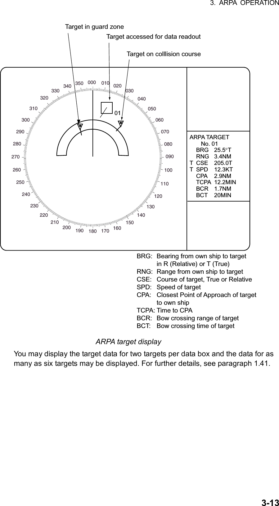
![3. ARPA OPERATION 3-14 [TARGET LIST (1/1)] SORT BY CPA 1 BACK 2 ARPA TARGET No. 001 BRG 16.5°T RNG 2.05 NM CPA 0.17NM TCPA>99.59M3 ARPA TARGET No. 002 BRG 19.0°T RNG 2.49 NM CPA 0.29NM TCPA>99.59M 9 REFRESH DATA 3.8.2 Target list The target list provides a comprehensive data display of all ARPA (and AIS) targets being tracked. Displaying the target list To display the target list, do the following: 1. Roll the trackball to choose the TARGET LIST box at the right side of the screen. TARGETLIST TARGET LIST box 2. Push the left button to display the TARGET LIST. “>” in the TCPA means that the time is greater than 99:59. Target list 3. To scroll the list when there are more than three targets, select 0 NEXT and then push the wheel or the left button. Note: To refresh data choose 9 REFRESH DATA and then push the wheel. This is not necessary when the sorting method is changed (see next page); data is automatically updated whenever the sorting method is changed. 4. Push the right button to close the list.](https://usermanual.wiki/Furuno-USA/9ZWRTR078/User-Guide-356443-Page-132.png)
![3. ARPA OPERATION 3-15 [TARGET LIST MENU] 1 SORT BY CPA/TCPA/BCR/BCT/ RANGE/SPEED Sorting the target list You may sort the target list by CPA, TCPA, BCR, BCT, RANGE or SPEED as follows: 72 nm or 96 nm range scale 1. Roll the trackball to choose the TARGET LIST box at the right side of the screen. 2. Push the right button to open the TARGET LIST menu. TARGET LIST menu 3. Roll the wheel to choose 1 SORT BY and then push the wheel or the left button. 4. Roll the wheel to choose sorting method desired and then push the wheel or the left button. 5. Push the right button to close the menu.](https://usermanual.wiki/Furuno-USA/9ZWRTR078/User-Guide-356443-Page-133.png)
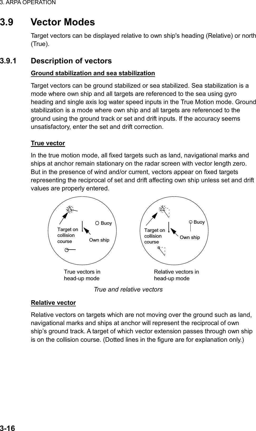
![3. ARPA OPERATION 3-173.9.2 Vector motion and length Vectors may be displayed in true or relative motion. Vector time (or the length of vectors) can be set to 30 seconds, 1, 2, 3, 6, 12, 15 or 30 minutes. By keyboard 1. Press the [VECTOR MODE] key consecutively to choose relative or true vector mode. Your selection is shown on the Vector motion box. (Note that this also selects the vector mode for the past position display.) 2. Press the [VECTOR TIME] key consecutively to choose vector time. Your selection appears in the vector length box (see illustration below). By trackball 1. Roll the trackball to choose VECTOR TRUE or VECTOR REL (whichever is displayed) at the right side of the screen. VECTOR TRUE 15MINVector motionVectorlength ARPA VECTOR boxes 2. Push the left button to display VECTOR TRUE or VECTOR REL as appropriate. (Note that this also selects the vector mode for the past position display.) 3. Roll the trackball to choose the vector length box. 4. Push the left button to display time desired. The vector tip shows an estimated position of the target after the selected vector time elapses. It can be valuable to extend the vector length to evaluate the risk of collision with any target.](https://usermanual.wiki/Furuno-USA/9ZWRTR078/User-Guide-356443-Page-135.png)
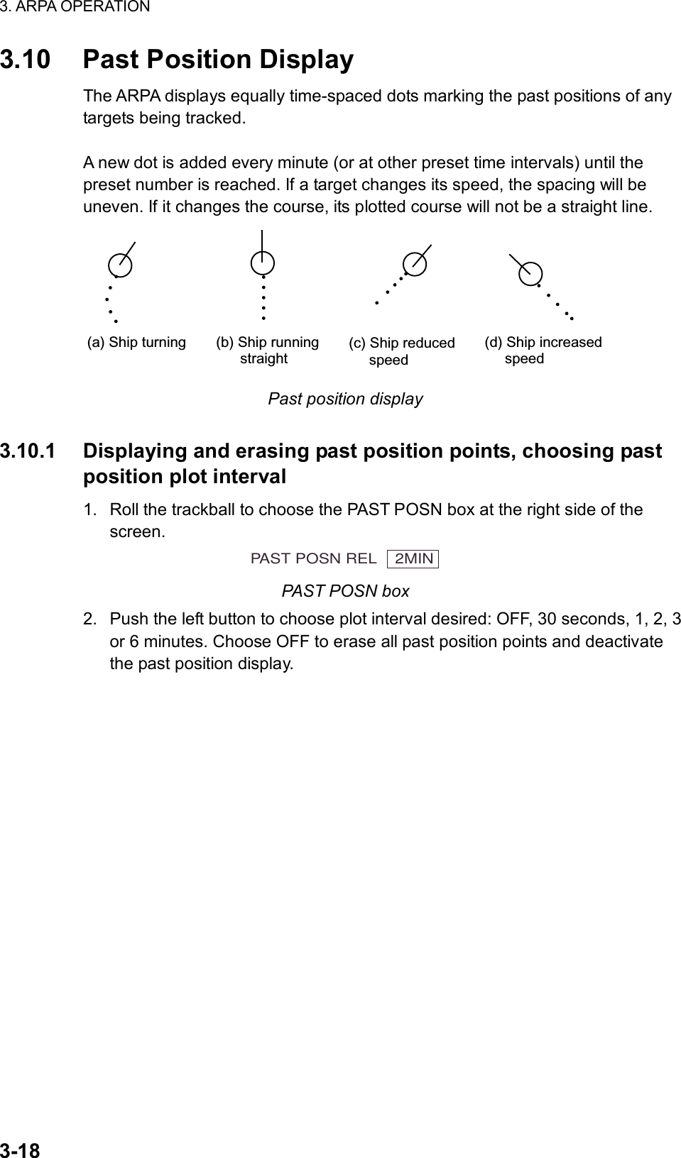
![3. ARPA OPERATION 3-19 [ARPA•AIS MENU] 1 BACK 2 GUARD ZONE STAB STAB HDG/STAB NORTH 3 GUARD POLYGON OFF/STAB GND/ STAB HDG/STAB NORTH 4 [TRIAL MANEUVER] 5 [ARPA SYMBOL] 6 [AIS SYMBOL] 7 [FUSION] 8 AIS FUNCTION OFF/ON [ARPA SYMBOL] 1 BACK 2 ARPA SYMBOL COLOR RED/GRN/BLU/YEL/ CYA/MAG/WHT 3 ARPA SYMBOL SIZE SMALL/STD/LARGE 4 ARPA PAST POSN COLOR RED/GRN/BLU/YEL/ CYA/MAG/WHT 5 ARPA PAST POSN POINTS 5/10 3.10.2 Past position display attributes You may choose the number of past point points to display per plotting interval and the color of past position points. 1. Roll the trackball to choose the MENU box at the right side of the screen and then push the left button. 2. Roll the wheel to choose 4 ARPA•AIS and then push the wheel or the left button. ARPA•AIS menu 3. Roll the wheel to choose 5 [ARPA SYMBOL] and then push the wheel or the left button. ARPA SYMBOL menu 3. Roll the wheel to choose 4 ARPA PAST POSN COLOR and then push the wheel or the left button. 4. Roll the wheel to choose color desired and then push the wheel or the left button. 5. Roll the wheel to choose 5 ARPA PAST POSN POINTS and then push the wheel or the left button. 6. Roll the wheel to choose 5 or 10 as appropriate and then push the wheel or the left button. 7. Push the right button three times to close the menu.](https://usermanual.wiki/Furuno-USA/9ZWRTR078/User-Guide-356443-Page-137.png)
![3. ARPA OPERATION 3-20 [SPEED MENU] 1 SHIP SPEED LOG(BT)/LOG(WT)/ GPS/MANUAL/REF 2 MANUAL SPEED 00.0kt 3 SET DRIFT OFF/ON 3.11 Set and Drift Set, the direction in which a water current flows, can be manually entered in 0.1-degree steps. Drift, in another word Rate, the speed of tide, can also be entered manually in 0.1 knot steps. Set and drift corrections are beneficial for increasing the accuracy of vectors and target data. Refer to the tide table on board the ship for setting information. If SOG and COG are the only available data, set and drift can provide sea stabilizing. These values are applied to all targets. If stationary targets have vectors, set and drift values should be adjusted until they lose vectors. To enter set and drift do the following: 1. Roll the trackball to choose the SET box at the right side of the screen. SET 66.8 T SET box 2. Use the wheel to set value, rolling it to choose numeral and pushing it to set. (Setting range: 000.0 – 359.9 (°T) 3. Roll the trackball to choose the DRIFT box at the right side of the screen. DRIFT 7.2kt DRIFT box 4. Use the wheel to set value, rolling it to choose numeral and pushing it to set. (Setting range: 00.0 – 19.9(kt)) 5. Roll the trackball to choose the SPD box and then push the right button. SPEED menu 6. Roll the wheel to choose 3 SET DRIFT and then push the wheel or the left button. 7. Roll the wheel to choose ON and then push the wheel or the left button. 8. Push the right button to close the menu.](https://usermanual.wiki/Furuno-USA/9ZWRTR078/User-Guide-356443-Page-138.png)
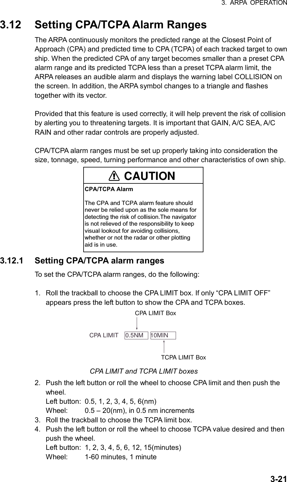
![3. ARPA OPERATION 3-22 3.12.2 Acknowledging CPA/TCPA alarm To acknowledge and silence the CPA/TCPA alarm, press the [ALARM ACK] key on the keyboard, or choose the ALARM ACK box with the trackball and then push the left button. The warning label COLLISION and the flashing of the triangle plotting symbol and vector remain on the screen until the dangerous situation is gone or you intentionally terminate tracking of the target.](https://usermanual.wiki/Furuno-USA/9ZWRTR078/User-Guide-356443-Page-140.png)
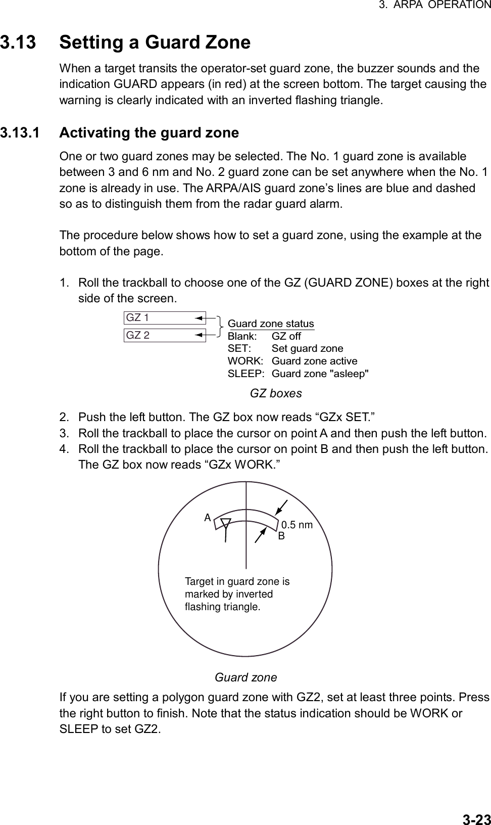
![3. ARPA OPERATION 3-24 When an ARPA or AIS target violates the guard zone, the message “GUARD” appears (in red) at the right side of the display and the offending target is marked with an inverted triangle. Note 1: If you wish to create a guard zone having a 360-degree coverage around own ship, set point B in almost the same direction (approx. ±3°) as point A and then push the left button. Note 2: If the range scale is changed to less than half of the guard zone, the GZ box reads “GZx OUT.” If the left button is pushed in this state, the guard alarm zone goes into “sleep” state and the guidance box reads “GZ WORK L = DELETE.” Note 3: The default guard zone is fan shaped. It may also be a polygon having 3-10 points. For details, see paragraph 3.13.5. Note 4: Two more alarm zones (No. 1 and No. 2 Guard Alarm Zones) may be added in addition. This means a maximum 4 alarm zones are available at a time. ARPA symbols are not changed to inverted triangles in the guard alarm zone, only those in guard zone do so. 3.13.2 Sleeping, deactivating a guard zone 1. Roll the trackball to choose the appropriate GZ box. 2. Sleep or deactivate the guard zone as appropriate: Sleep guard zone: Push the left button momentarily to remove the guard zone from the screen. The indication in the GZ box changes from “GZx WORK” to “GZx SLEEP.” To reactivate and display the guard zone, repeat this procedure to display “GZx WORK.” Deactivate guard zone: Push and hold down the left button until the GZ box goes blank. 3.13.3 Acknowledging the guard zone alarm To acknowledge and silence the guard zone audible alarm, press the [ALARM ACK] key, or choose the ALARM ACK box and then push the left button.](https://usermanual.wiki/Furuno-USA/9ZWRTR078/User-Guide-356443-Page-142.png)
![3. ARPA OPERATION 3-25 [ARPA•AIS MENU] 1 BACK 2 GUARD ZONE STAB STAB HDG/STAB NORTH 4 GUARD POLYGON OFF/STAB GND/ STAB HDG/STAB NORTH 4 [TRIAL MANEUVER] 5 [ARPA SYMBOL] 6 [AIS SYMBOL] 7 [FUSION] 8 AIS FUNCTION OFF/ON3.13.4 Guard zone reference The guard zone may be referenced to heading or North as follows: 1. Roll the trackball to choose the MENU box at the right side of the screen and then push the left button. 2. Roll the wheel to choose 4 ARPA•AIS and then push the wheel or the left button. ARPA•AIS menu 3. Roll the wheel to choose 2 GUARD ZONE STAB and then push the wheel or the left button. 4. Roll the wheel to choose STAB HDG or STAB NORTH as appropriate and then the push the wheel or the left button. 5. Push the right button twice to close menu. 3.13.5 Guard zone shape and stabilization The shape of the No. 2 guard zone may be a sector or a polygon having up to 10 points. (The shape of the No.1 guard zone is always a sector.) 1. Roll the trackball to choose the MENU box at the right side of the screen and then push the left button. 2. Roll the wheel to choose 4 ARPA•AIS and then push the wheel or the left button. 3. Roll the wheel to choose 3 GUARD POLYGON and then push the wheel or the left button. 4. Roll the wheel to choose OFF, STAB GND, STAB HDG or STAB NORTH as appropriate and then the push the wheel or the left button. OFF: Guard zone is a sector; number of points limited to four. STAB GND: Guard zone stabilized against ground; guard zone may be a polygon having 3-10 points. STAB HDG: Guard zone stabilized against heading; guard zone may be a polygon having 3-10 points. STAB NORTH: Guard zone stabilized against ground; guard zone may be a polygon having 3-10 points. 5. Push the right button twice to close menu.](https://usermanual.wiki/Furuno-USA/9ZWRTR078/User-Guide-356443-Page-143.png)
![3. ARPA OPERATION 3-26 3.14 Operational Warnings There are six main situations which cause the ARPA to trigger visual and audible alarms: • CPA/TCPA alarm • Guard zone alarm • Lost target alarm • Target full alarm for manual acquisition • Target full alarm for automatic acquisition • System failure CPA/TCPA alarm Visual and audible alarms are generated a target falls with a preset limits. To acknowledge the CPA/TCPA audible alarm, press the [ALARM ACK] key, or choose the ALARM ACK box and then push the left button. Guard zone alarm Visual and audible alarms are generated when a target transits the operator-set guard zone. To acknowledge and silence the guard alarm, press the [ALARM ACK] key, or choose the ALARM ACK box and then push the left button. Lost target alarm When the system detects a loss of a tracked target, the target symbol becomes a flashing diamond ( ) and the label “LOST” appears at the screen bottom. At the same time, an audible alarm is produced for one second. To acknowledge and silence the lost target audible alarm, press the [ALARM ACK] key, or choose the ALARM ACK box and then push the left button. Then, the lost target mark disappears. Target full alarm When the memory becomes full, the memory full status is indicated and the relevant indication appears on the screen and a short beep sounds. Manually acquired targets The indication “TARGET-FULL(MAN)” appears at the screen bottom and a short beep tone sounds when the capacity for manually acquired targets, as set on the menu, is reached.](https://usermanual.wiki/Furuno-USA/9ZWRTR078/User-Guide-356443-Page-144.png)
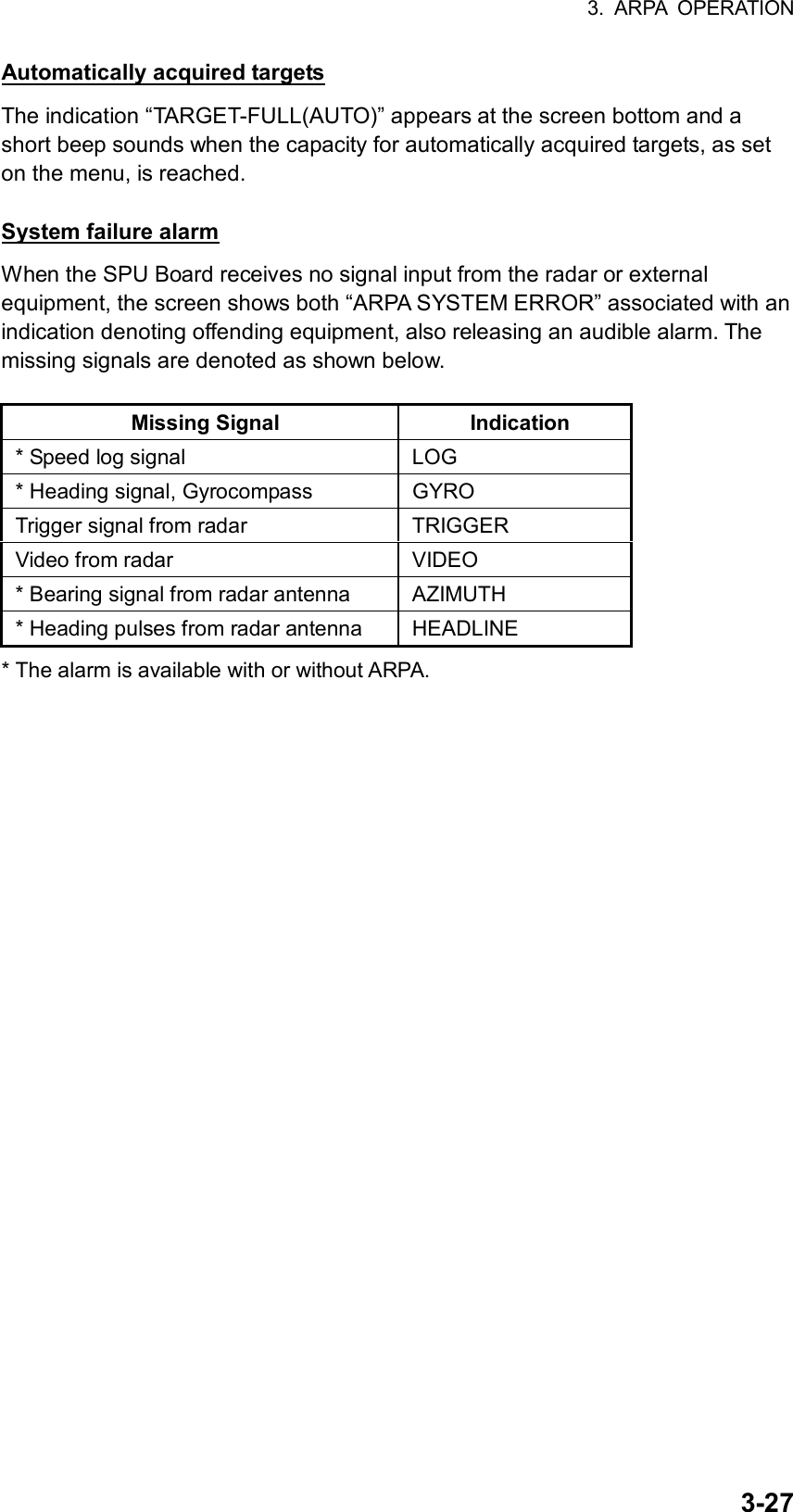
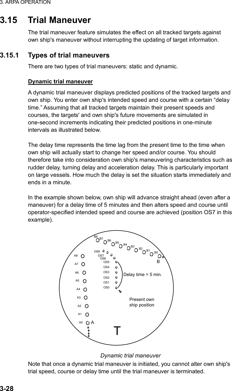
![3. ARPA OPERATION 3-29 [ARPA•AIS MENU] 1 BACK 2 GUARD ZONE STAB STAB HDG/STAB NORTH 5 GUARD POLYGON OFF/STAB GND/ STAB HDG/STAB NORTH 4 [TRIAL MANEUVER] 5 [ARPA SYMBOL] 6 [AIS SYMBOL] 7 [FUSION] 8 AIS FUNCTION OFF/ON Static trial maneuver A static trial maneuver displays only the final situation of the simulation. If you enter the same trial speed, course and delay time under the same situation as in the aforementioned example of dynamic trial maneuver, the screen will instantly show position OS7 for own ship, position A7 for target A and position B7 for target B, omitting the intermediate positions. Thus, the static trial maneuver will be convenient when you wish to know the maneuver result immediately. Note: For accurate simulation of ship movements in a trial maneuver, own ship's characteristics such as acceleration and turning performance should be properly set in initial settings during the installation. 3.15.2 Performing a trial maneuver To perform a trial maneuver, do the following: 1. Roll the trackball to choose the MENU box at the right side of the screen and then push the left button. 2. Roll the wheel to choose 4 ARPA•AIS and then push the wheel or the left button. ARPA•AIS menu](https://usermanual.wiki/Furuno-USA/9ZWRTR078/User-Guide-356443-Page-147.png)
![3. ARPA OPERATION 3-30 [TRIAL MANEUVER] 1 BACK 2 TRIAL OFF/STATIC/ DYNAMIC 3 TRIAL SPEED RATE 0kt 0.00kt/s 0kt 0.00kt/s 4 TRIAL TURN RATE 0kt 0.0°/s 0kt 0.0°/s 3. Roll the wheel to choose 4 TRIAL MANEUVER and then push the wheel or the left button. TRIAL MANEUVER menu 4. Roll the wheel to choose 2 TRIAL and then push the left button or the wheel. 5. Roll the wheel to choose STATIC or DYNAMIC as appropriate and then push the wheel or the left button. 6. Roll the wheel to choose 3 TRIAL SPEED RATE. Set trial speed rate with the wheel: Roll the wheel to choose numeral; push the wheel to set. 7. Roll the wheel to choose 4 TRIAL TURN RATE. Set trial turn rate with the wheel: Roll the wheel to choose numeral; push the wheel to set. Note: Two sets of trial speed and trial turn rate combinations are provided. Enter the data by sets as shown in the figure below. This is done to provide accurate trial maneuver results for various ship’s speed. 3 TRIAL SPEED RATE 4 TRIAL TURN RATE Set 10kt 0.00kt/s0kt 0.00kt/sSet 2Set 10kt 0.0 /s0kt 0.0 /sSet 2 8. Push the right button three times to close the menu. The “trial maneuver boxes” appear at the right side of the screen as below. TRIAL 00:00 CSE 000.0°T SPD 00.0 KT Trial maneuver boxes 9. Roll the trackball to choose the TRIAL box and then push the wheel or the left button. 10. Set the trial delay time with the wheel. This is the time after which own ship takes a new situation, not the time the simulation begins. Change the delay time according to own ship loading condition, etc. Roll the wheel to choose location; push the wheel to set. 12. Roll the wheel to choose the CSE box (below the TRIAL box). Use the wheel to set the course: Roll the wheel to choose location; push the wheel to set.](https://usermanual.wiki/Furuno-USA/9ZWRTR078/User-Guide-356443-Page-148.png)
![3. ARPA OPERATION 3-32 [CUSTOMIZE•TEST MENU] 1 BACK 2 [DATA BOX] 3 [F1] 4 [F2] 5 [F3] 6 [F4] 7 [OPERATION] 8 [TEST] [TEST] 1 BACK 2 [SELF TEST] 3 [ARPA TEST] [ARPA TEST] 1 BACK 2 ARPA TEST START NOTE: THE DISPLAY IS CLEARER WHEN RUNNING ARPA TEST. RUN ARPA TEST? YES: SELECT 2 START NO: SELECT 1 BACK 3.16 ARPA Performance Test A test program is provided for assessing overall performance of the ARPA. Normal operation is suspended and the indication “XX” appears at the bottom of the effective display area during the test. The test may be terminated at any time. 1. Roll the trackball to choose the MENU box and then push the left button. 2. Roll the wheel to choose 9 [CUSTOMIZE•TEST] and then push the wheel or the left button. CUSTOMIZE•TEST menu 3. Roll the wheel to choose 8 [TEST] and then push the wheel or the left button. TEST menu 4. Roll the wheel to choose 3 [ARPA TEST]. ARPA TEST menu](https://usermanual.wiki/Furuno-USA/9ZWRTR078/User-Guide-356443-Page-150.png)
![3. ARPA OPERATION 3-335. Roll the wheel to choose 2 ARPA TEST START and then push the wheel or the left button to start the test. An alert “XX” flickers during the test. It takes approximately three minutes for all vectors to be displayed. The test does not need echo signals, gyro nor speed log input. Seven targets having different speeds and courses, as shown in the table on the next page, are simulated automatically. 6. The test continues for five minutes and then repeats. To terminate the test, press the [STBY TX] key or choose the TX STBY box at the bottom left corner and then push the left button. Select any target with the cursor and check that the selected target shows the course and speed as in the table. CPA and TCPA shown in the table are initial values which change with time. Target Course Speed CPA TCPA (kt) (nm) (min)Target A 10.0 1.0 10.4 Target B 0.0 4.0 - Target C 10.0 1.7 28.2 Target D 23.8 0.9 15.0 Target E 14.2 6.0 22.5 Target F 20.0 0.0 30.0 Target G 15.6 4.0 43.6 000 010 020030040050060070080090100110120130140150160170180190200210220230240250260270280290300310320330340 350FEDCXXB ARPA performance test targets](https://usermanual.wiki/Furuno-USA/9ZWRTR078/User-Guide-356443-Page-151.png)
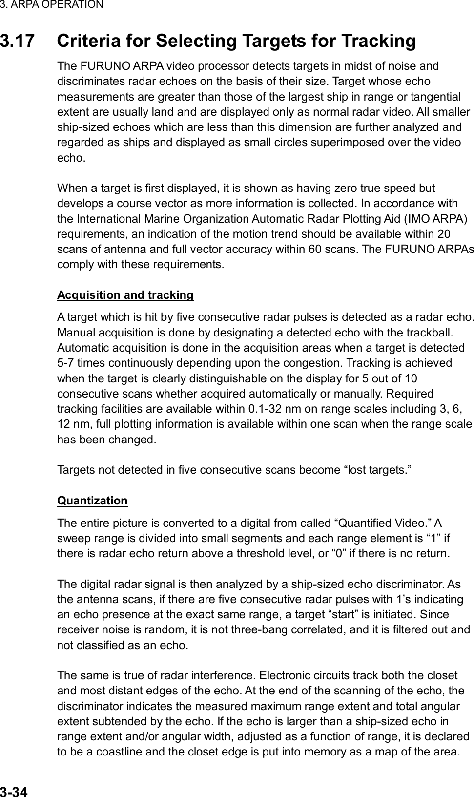
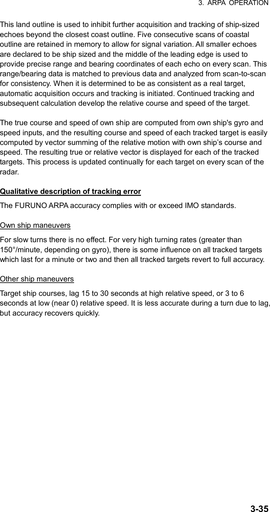
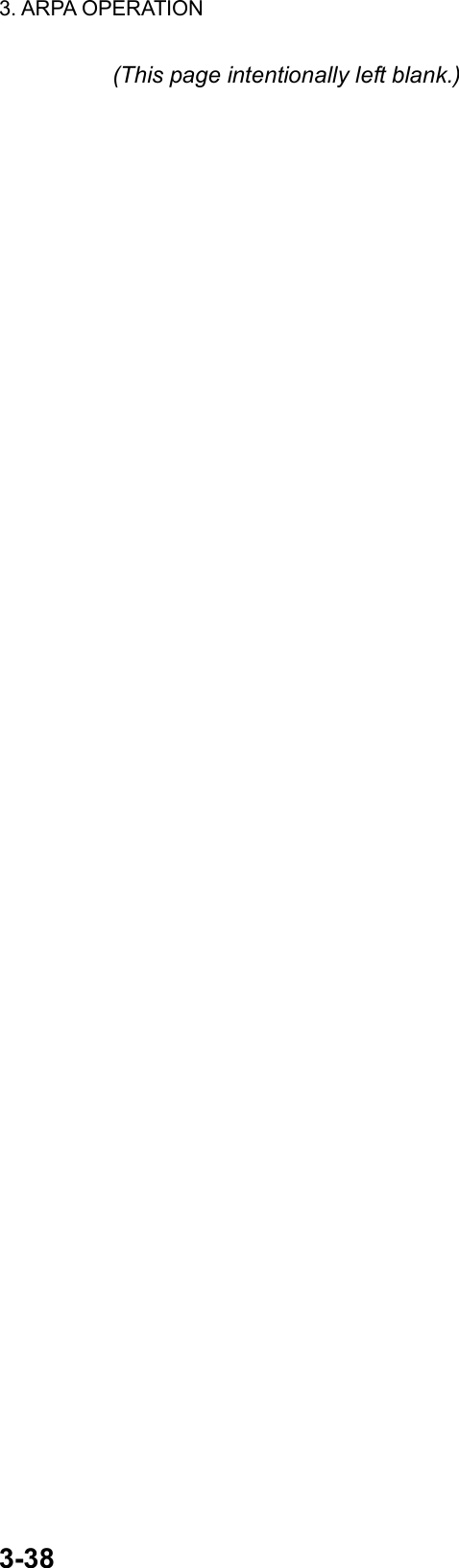
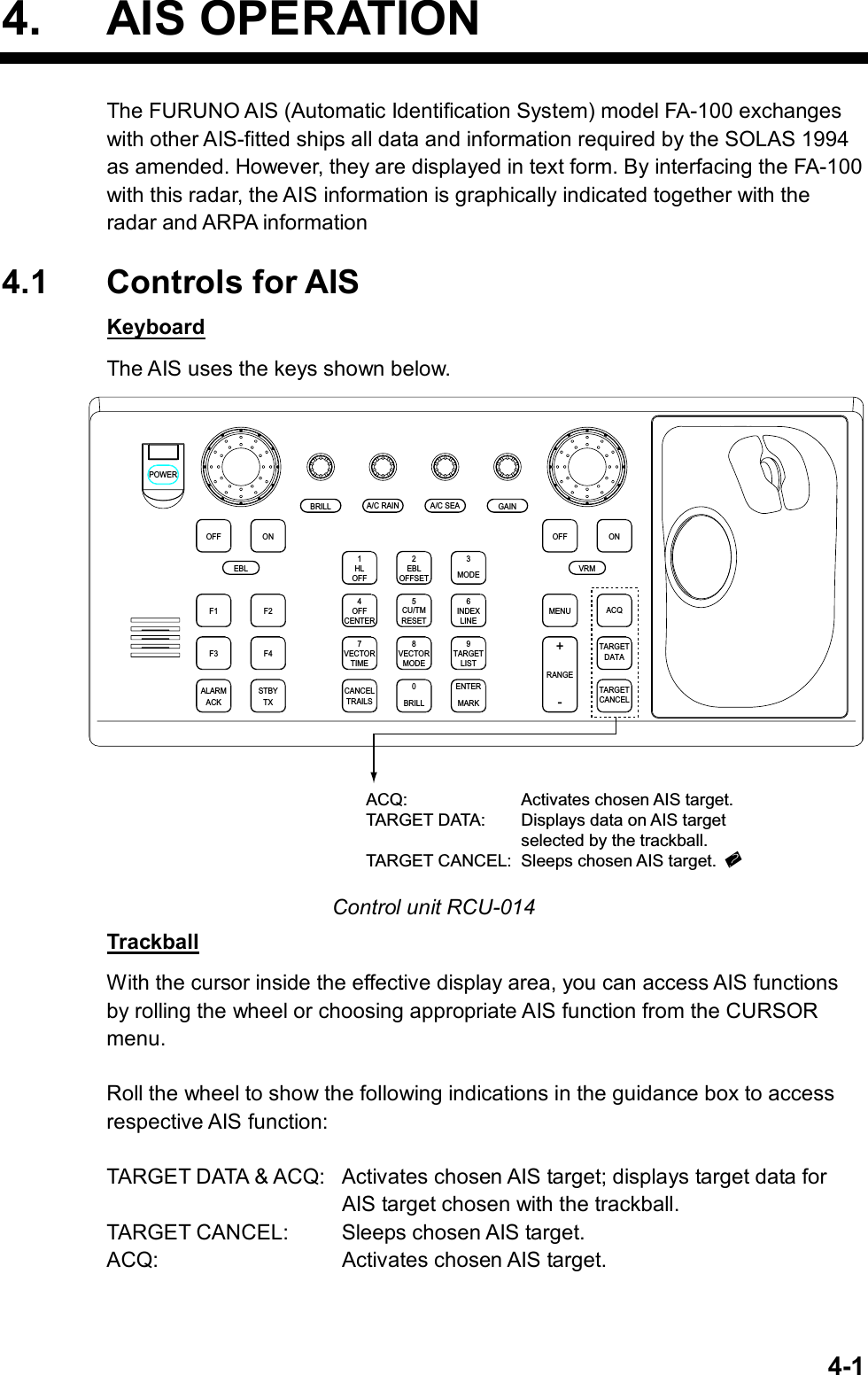
![4. AIS OPERATION 4-2 [ARPA•AIS MENU] 1 BACK 2 GUARD ZONE STAB STAB HDG/STAB NORTH 3 GUARD POLYGON OFF/STAB GND/ STAB HDG/STAB NORTH 4 [TRIAL MANEUVER] 5 [ARPA SYMBOL] 6 [AIS SYMBOL] 7 [FUSION] 8 AIS FUNCTION OFF/ON 4.2 Enabling/Disabling the AIS 1. Roll the trackball to choose the MENU box at the right side of the screen and then push the left button. 2. Roll the wheel to choose 4 ARPA•AIS and then push the wheel or the left button. ARPA•AIS menu 3. Roll the wheel to choose 8 AIS FUNCTION and then push the wheel or the left button. 4. Roll the wheel to choose OFF or ON as appropriate and then push the wheel or the left button. 5. Push the right button three times to close the menu. “AIS” appears at the lower right hand corner of the screen when the AIS function is active.](https://usermanual.wiki/Furuno-USA/9ZWRTR078/User-Guide-356443-Page-158.png)
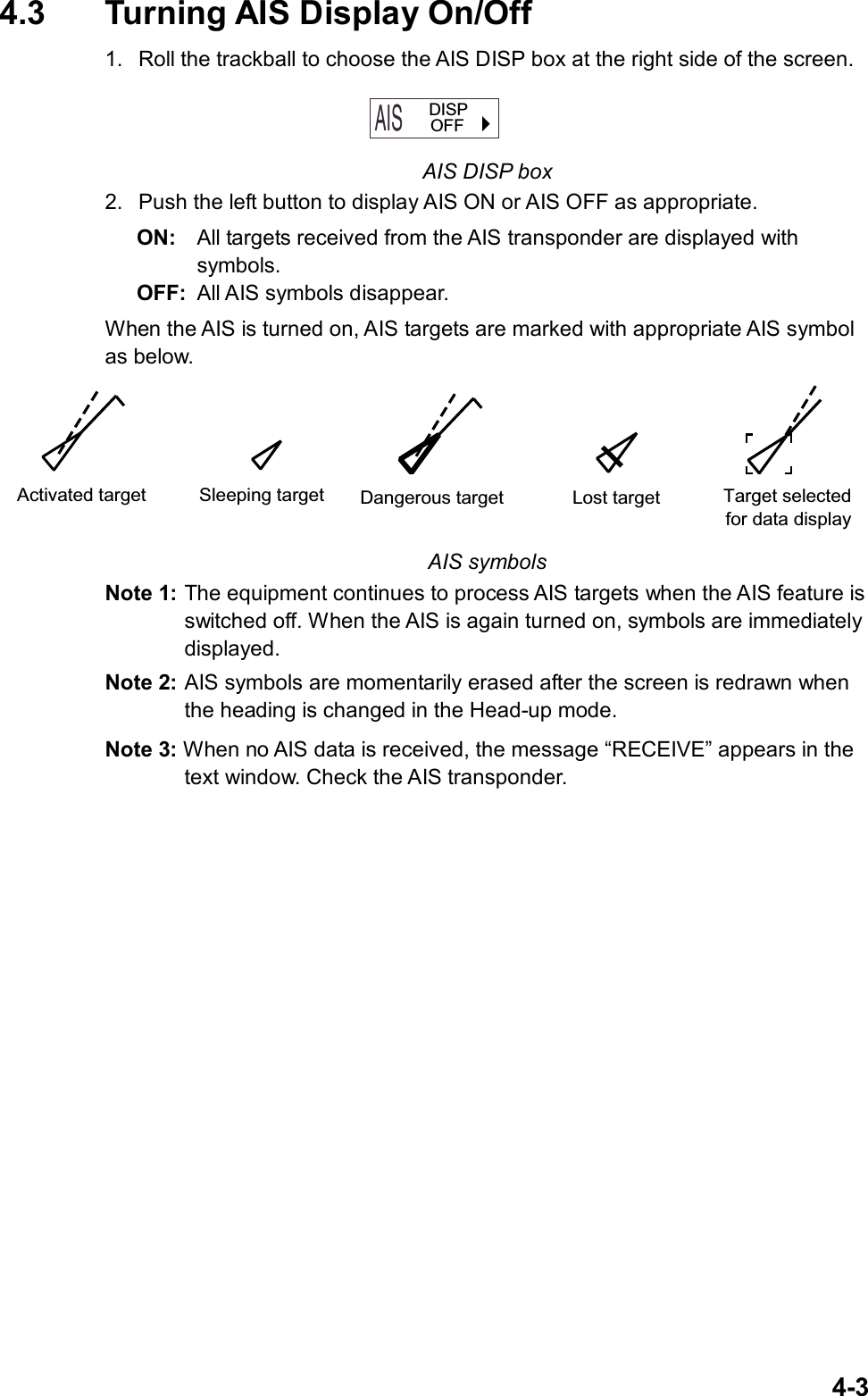
![4. AIS OPERATION 4-4 4.4 Activating Targets When you convert a sleeping target to an activated target, that target’s course and speed are shown with a vector. You can easily judge target movement by monitoring the vector. 4.4.1 Activating specific target By keyboard 1. Roll the trackball to place the cursor on the AIS target you wish activate. 2. Press the [ACQ] key to activate the target. By trackball 1. With the cursor inside the effective display area, roll the wheel to display “TARGET DATA & ACQ / CURSOR MENU” in the guidance box. 2. Roll the trackball to place the cursor on the sleeping AIS target you wish to activate; that is, know more about a vessel’s motion. 3. Push the left button to activate the target. Heading line#SOG (Speed over Ground)and COG (Course over Ground) vector*1Turning direction(ROT)*1 = Vector shows STW (speedthru water) and CSE(course) when watertracking mode isselected at the radar.# = If there is no heading data,the line points in direction of COG. Activated target 4.4.2 Activating all targets 1. Roll the trackball to choose the AIS DISP box at the right side of the screen. 2. Push the right button to open the AIS TARGET menu. 3. Roll the wheel to choose 2 ACTIVATE ALL TGTS and then push the wheel or the left button. 4. Push the right button to close the menu. Thicker thanactivated target Dangerous targetWhen an activated target violates the CPA/TCPAalarm setting its symbol changes to the dangeroustarget symbol (red and flashing) and the indication COLLISON appears. Press the [ALARM ACK] key (or click the ALARM ACK box with the left button)to acknowledge the CPA/TCPA alarm. The audiblealarm is silenced and the symbol stops flashing.Take appropriate action to avoid collision.](https://usermanual.wiki/Furuno-USA/9ZWRTR078/User-Guide-356443-Page-160.png)
![4. AIS OPERATION 4-5 [AIS TARGET MENU] 1 SLEEP ALL TGTS 2 ACTIVATE ALL TGTS 3 AUTO DISPLAY MESSAGE OFF/ON 4 [RECEIVED MSGS] 5 6 7 8 [AIS ALARM MSGS] 4.5 Sleeping Targets 4.5.1 Sleeping an AIS target You may “sleep” an AIS target as below when the screen becomes filled with targets which might prevent important radar and AIS displays from being identified. Note that targets that have been activated automatically cannot be “slept.” (See paragraph 4.7.) 1. With the cursor inside the effective display area, roll the wheel to display “TARGET CANCEL / EXIT” in the guidance box. 2. Roll the trackball to place the cursor on an activated AIS target symbol. 3. Push the left button. The activated target symbol should be replaced with the sleeping target symbol. Sleeping target 4.5.2 Sleeping all AIS targets 1. Roll the trackball to choose the AIS DISP box at the right side of the screen. 2. Push the right button to open the AIS TARGET menu. AIS TARGET menu 3. Roll the wheel to choose 1 SLEEP ALL TGTS. 4. Push the left button or the wheel to sleep all targets. 5. Push the right button to close the menu.](https://usermanual.wiki/Furuno-USA/9ZWRTR078/User-Guide-356443-Page-161.png)
![4. AIS OPERATION 4-6 4.6 Displaying Target Data You may display an AIS target’s data by selecting it on the display. 4.6.1 Basic data By keyboard 1. Roll the trackball to place the cursor on the AIS target symbol you want to know its data. 2. Press the [TARGET DATA] key. By trackball 1. With the cursor inside the effective display area, roll the wheel to display “TARGET DATA & ACQ / CURSOR MENU”. 2. Roll the trackball to place the cursor on an AIS target symbol and then push the wheel or the left button. The selected target is marked with a broken square and AIS data is shown in the AIS data box when the target is correctly selected. Activated target selected for data display AIS TARGET NAMEFURUNO BRG 208.6°T HDG RNG 12.3NM 12.0°TT CSE 9.0°T* ROT°/MINT SPD 8.2kt# 1.1R CPA 5.32NM CALL TCPA 33:31R 1436782 BCR 5.65NM MMSI BCT 25:30 0123456000 * = CSE (course) when water tracking mode is selected at radar.# = STW (speed thru water) when water tracking mode is selected at radar.Call signMMSI No.Rate of turnHeadingBearing to targetRange to targetTarget’s courseTarget’s speedTarget’s CPATarget’s TCPATarget’s bow cross rangeTarget’s bow cross time AIS data display](https://usermanual.wiki/Furuno-USA/9ZWRTR078/User-Guide-356443-Page-162.png)
![4. AIS OPERATION 4-74.6.2 Detailed target data 1. Roll the trackball to place the cursor on the desired AIS target in the data box at the right side of the screen. 2. Push the left button to show detailed data. [EXPANDED DATA(1/1)]1 BACKNAME: VOYAGERCALL: 1436782 LAT: 34 44.2345’NLON: 135 32.1890’EPOS. SNS: GPSPOSITION ACC: HIGHNAV. STATE: ANCHOR MMSI: 107374182IMO: 12354876SHIP LENGTH: 187mSHIP WIDTH: 28mSHIP DRAFT: 12.2mDESTINATION OsakaETA: 01/FEB 12:59AIS VERSION: 0FUSION: OFF TYPE OF SHIP & CARGO TYPE: Fishing Ship’s nameCall signLatitudeLongitudePosition fixing devicePosition accuracy (HIGH, LOW)Navigation statusMMSI No.IMO No.LengthWidthDraftDestinationEstimated Time of ArrivalAIS program no.Fusion ON/OFFType of ship and cargo](https://usermanual.wiki/Furuno-USA/9ZWRTR078/User-Guide-356443-Page-163.png)
![4. AIS OPERATION 4-8 4.7 AIS Symbol Attributes You may adjust the brilliance and choose the size and color of the AIS symbol. 4.7.1 AIS symbol brilliance 1. Roll the trackball to choose the BRILL box at the left side of the screen and then push the right button. 2. Roll the wheel to choose 0 NEXT and then push the wheel or the left button. [BRILL1 MENU (2/2)]1 BACK2 BEARING CURSOR3 EBL4 VRM5 INDEX LINE6 ARPA SYMBOL7 AIS SYMBOL8 L/L GRID9 MARK0 CHART BRILL menu, page 2 3. Roll the wheel to choose 7 AIS SYMBOL and then push the wheel or the left button. 4. Roll the wheel to adjust brilliance. 5. Push the right button twice to close the menu.](https://usermanual.wiki/Furuno-USA/9ZWRTR078/User-Guide-356443-Page-164.png)
![4. AIS OPERATION 4-9 [AIS SYMBOL] 1 BACK 2 AIS SYMBOL COLOR RED/GRN/BLU/YEL/ CYA/MAG/WHT 3 AIS SYMBOL SIZE SMALL/STD/LARGE 4 ROT TAG LIMIT 000.0°/min 5 AIS PAST POSN COLOR RED/GRN/BLU/YEL/ CYA/MAG/WHT 6 AIS PAST POSN POINTS 5/10 4.7.2 AIS symbol size and color You may choose the size and color of the AIS symbol as follows: 1. Roll the trackball to choose the MENU box and then push the left button. 2. Roll the wheel to choose 4 [ARPA•AIS] and then push the wheel or the left button. 3. Roll the wheel to choose 6 [AIS SYMBOL] and then push the wheel or the left button. AIS SYMBOL menu 4. Roll the wheel to choose 2 AIS SYMBOL COLOR and then push the wheel or the left button. 5. Roll the wheel to choose color desired and then push the wheel or the left button. 6. Roll the wheel to choose 3 AIS SYMBOL SIZE and then push the wheel or the left button. 7. Roll the wheel to choose SMALL, STD(Standard) or LARGE as appropriate and then push the wheel or the left button. 8. Push the right button three times to close the menu.](https://usermanual.wiki/Furuno-USA/9ZWRTR078/User-Guide-356443-Page-165.png)
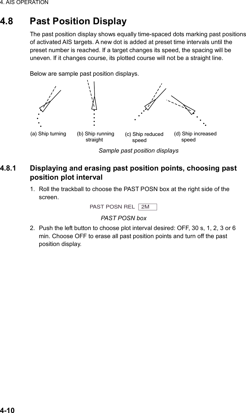
![4. AIS OPERATION 4-11 [AIS SYMBOL] 1 BACK 2 AIS SYMBOL COLOR RED/GRN/BLU/YEL/ CYA/MAG/WHT 3 AIS SYMBOL SIZE SMALL/STD/LARGE 4 ROT TAG LIMIT 000.0°/min 5 AIS PAST POSN COLOR RED/GRN/BLU/YEL/ CYA/MAG/WHT 6 AIS PAST POSN POINTS 5/10 4.8.2 Past position display attributes You may choose the number of past position points to show per plot interval and the color of past position points. 1. Roll the trackball to choose the MENU box and then push the left button. 2. Roll the wheel to choose 4 ARPA•AIS and then push the wheel or the left button. 3. Roll the wheel to choose 7 [AIS SYMBOL] and then push the wheel or the left button. AIS SYMBOL menu 4. Roll the wheel to choose 5 AIS PAST POSN COLOR and then push the wheel or the left button. 5. Roll the wheel to choose color desired and then push the wheel or the left button. 6. Roll the wheel to choose 6 AIS PAST POSN POINTS and then push the wheel or the left button. 7. Roll the wheel to choose 5 or 10 as appropriate and then push the wheel or the left button. 8. Push the right button three times to close the menu.](https://usermanual.wiki/Furuno-USA/9ZWRTR078/User-Guide-356443-Page-167.png)
![4. AIS OPERATION 4-12 4.9 Lost Target A target is declared a lost target when a dangerous target fails to produce data for six minutes or five reporting intervals, whichever is the shorter. When this occurs, the target is marked with the (flashing) lost target symbol and the indication “LOST” appears. To acknowledge a lost target, press the [ALARM ACK] key or roll the trackball to choose the ALARM ACK box and then push the left button. Lost target Note 1: If an ARPA lost target mark is displayed when the [ALARM ACK] key is pressed (or the ALARM ACK box is clicked) to acknowledge an AIS lost target, the ARPA lost target will also be erased. Note 2: The AIS data transmission interval depends on own ship speed. For example, the data is transmitted every 10 seconds on ship speed of 0 to 14 kt and every two seconds on the ship speed of more than 23 knots. For details see the owner’s manual of the AIS.](https://usermanual.wiki/Furuno-USA/9ZWRTR078/User-Guide-356443-Page-168.png)
![4. AIS OPERATION 4-13 [AIS SYMBOL] 1 BACK 2 AIS SYMBOL COLOR RED/GRN/BLU/YEL/ CYA/MAG/WHT 3 AIS SYMBOL SIZE SMALL/STD/LARGE 4 ROT TAG LIMIT 000.0°/min 5 AIS PAST POSN COLOR RED/GRN/BLU/YEL/ CYA/MAG/WHT 6 AIS PAST POSN POINTS 5/10 4.10 ROT Setting You may set the lower limit of the ROT (Rate Of Turn) at which the heading line on target symbols will point in direction of turning of the vessel. 1. Roll the trackball to choose the MENU box and then push the left button. 2. Roll the wheel to choose 4 ARPA•AIS and then push the wheel or the left button. 3. Roll the wheel to choose 7 [AIS SYMBOL] and then push the wheel or the left button. AIS SYMBOL menu 4. Roll the wheel to choose 4 ROT TAG LIMIT and then push the wheel or the left button. 5. Use the numeral keys or the wheel to enter ROT (setting range: 0.1 to 180.0°/min). 6. Push the right button three times to close the menu. Ship turningto port ROT display](https://usermanual.wiki/Furuno-USA/9ZWRTR078/User-Guide-356443-Page-169.png)
![4. AIS OPERATION 4-14 [FUSION] 1 BACK 2 FUSION TARGET OFF/ON 3 GAP 0.000NM 4 RANGE 0.000NM 5 BEARING 00.0° 6 SPEED 0.00KT 7 COURSE 00.0° 4.11 Consolidating (fusing) ARPA and AIS Targets ARPA and AIS may be consolidated. The result is a single symbol whose position and vector is the result of an interpolation of the values of the separate symbols. This helps reduce clutter on the screen. Specify the parameters by which to consolidate ARPA and AIS targets as follows: 1. Confirm that the ARPA ACQ MODE box shows AUTO or AUTO MANU. 2. Roll the trackball to choose the MENU box and then push the left button. 3. Roll the wheel to choose 4 ARPA•AIS and then push the left button. 4. Roll the wheel to choose 8 [FUSION] and then push the left button. FUSION menu 5. Roll the wheel to choose FUSION TARGET and then push the wheel. 6. Roll the wheel to choose ON and then push the wheel. 8. Enter the information below, pushing the wheel (or the [MARK ENTER] key) after entering each data. This information will be used to determine which ARPA targets to convert. GAP: Range between AIS target and ARPA target. (0.000-0.999(nm)) RANGE: Enter the range difference from own ship to AIS target and ARPA target. (0.000-0.999(nm)) BEARING: Enter the bearing difference from own ship to AIS target and ARPA target. (0.0-9.9°) SPEED: Enter the speed difference between AIS target and ARPA target. (0.0-9.9 kt) COURSE: Enter the course difference between AIS target and ARPA target. (0.0-9.9°) 9. Push the right button three times to close the menu. If the information above is within the corresponding value of the ARPA and AIS targets, the targets are judged to be the same, the ARPA symbol is erased and only the AIS symbol is displayed. Further, “ARPA FUSION” appears at the bottom right corner of the display at the time of conversion and the ARPA target no. appears next to the AIS symbol. An ARPA target whose speed is less than 1 kt is converted to an AIS target if it meets all other criteria other than course.](https://usermanual.wiki/Furuno-USA/9ZWRTR078/User-Guide-356443-Page-170.png)
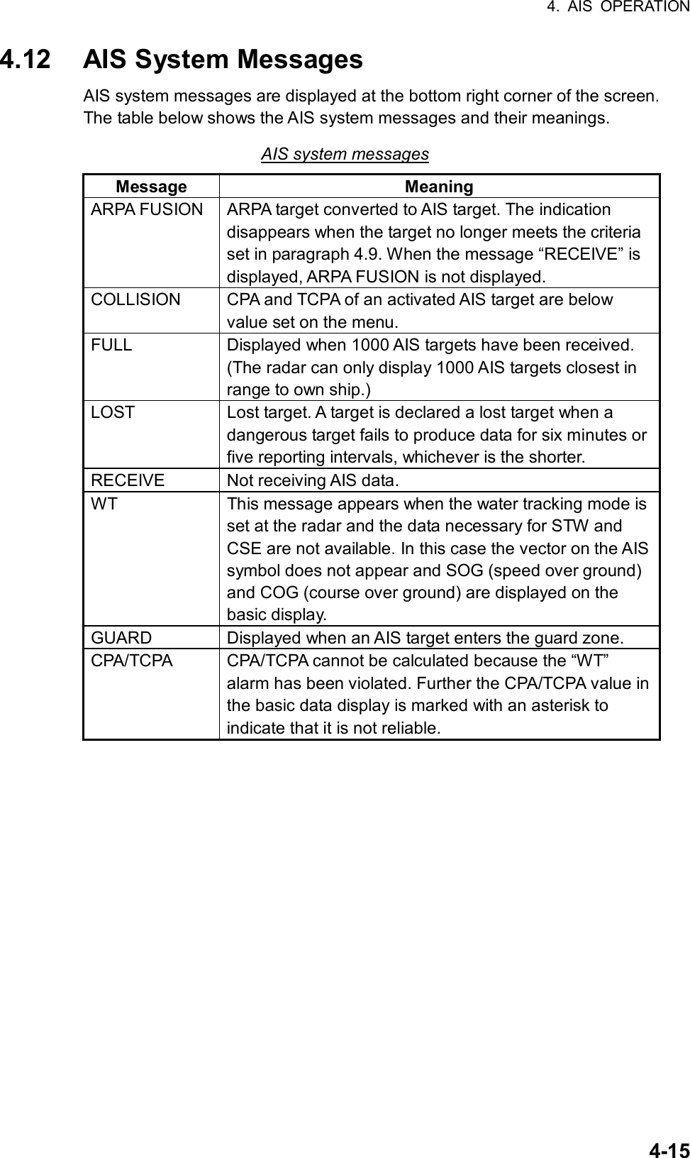
![4. AIS OPERATION 4-16 [AIS TARGET MENU] 1 SLEEP ALL TGTS 2 ACTIVATE ALL TGTS 3 AUTO DISPLAY MESSAGE OFF/ON 4 [RECEIVED MSGS] 5 6 7 8 [AIS ALARM MSGS] [RECEIVED MSGS] 1 BACK 2 DATE: 09JUN2003 12:34 TYPE: ADDRESSED SAFETY MMSI: 107374182 3 4 5 6 0 NEXT 4.13 Viewing AIS Messages When an AIS message is received, the display shows an appropriate icon to alert you. If you are set up to automatically display AIS messages they are automatically displayed upon receipt. The system stores up to 20 AIS messages. When the storage capacity is reached the oldest AIS message is automatically erased to make room for the latest. 4.13.1 Manually viewing received AIS messages To view received AIS messages do the following: 1. Roll the trackball to choose the AIS DISP box at the right side of the display. 2. Push the right button to open the AIS TARGET menu. AIS TARGET menu 3. Roll the wheel to choose 4 RECEIVED MSGS and then push the wheel or the left button. RECEIVED MESSAGES menu 4. Roll the wheel to choose the message which you want to see and then push the wheel or the left button.](https://usermanual.wiki/Furuno-USA/9ZWRTR078/User-Guide-356443-Page-172.png)
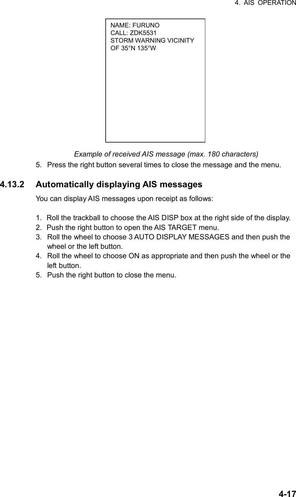
![5-1 5. VIDEO PLOTTER OPERATION 5.1 General The video plotter • Plots own and other ships’ tracks • Enters waypoints nav lines and marks • Records data onto memory cards (optional card interface required). It uses two types of memory cards, a memory card (RAM card) for storing own ship and other ship’s tracks and marks, and a digital chart card (ROM card). 30 nav lines may be stored and each line may contain up to 30 waypoints. Five nav lines may be simultaneously shown on the display. 200 waypoints are available. Own ship and other ship tracks may be stored at a selected interval. Charts are superimposed on the radar picture without disturbing the radar observation. The chart area is dependent on the radar range in use. 5.2 Display Modes This radar has two display modes: Radar and Radar + Video Plotter. Use the [MODE] key or the DISPLAY MODE box to choose a mode. (When the video plotter mode is displayed more than five seconds, the radar automatically goes into standby.) Note 1: Display mode cannot be chosen when the menu is open. Close the menu to choose a display mode. Note 2: The video plotter mode is not available when the radar map function is active (“MAP” appears at the right side of screen). Note 3: Only the radar display is available on the IMO-type radar.](https://usermanual.wiki/Furuno-USA/9ZWRTR078/User-Guide-356443-Page-174.png)
![5. VIDEO PLOTTER OPERATION 5-2Sample video plotter display 000 010 020030040050060070080090100110120130140150160170180190200210220230240250260270280290300310320330340 350W012W011North markerHeading markerWaypointNavlineOwn ship safe contourHeading linePlanned routeOwn ship vectorApproximate coastlineWaypointPast positionARPA/AIS: Equally time-spaced positions of any targets being tracked.Target being trackedSeparation zoneDangerous side of own ship safe contour may bemarked like this (hatchedline).AIS activated target Video plotter display 5.3 Presentation Modes Five presentation modes are available: North-up, Course-up, Head-up, Head-up TB (True Bearing) and North-up TM (True Motion). To choose a mode, use the [MODE] key or choose the PRESENTATION MODE box and then push the left button. For a description of the presentation modes, see paragraph 1.12. Note 1: Chart data is not displayed on the HEAD UP and HEAD UP TB modes. Note 2: The screen may flash when the heading is changed more than one degree in the HEAD UP or HEAD UP TB mode. Automatic resetting of own ship mark in true motion mode In the true motion mode, the own ship mark is automatically returned sternward 75% from the screen center when it reaches a location 75% of the display radius.](https://usermanual.wiki/Furuno-USA/9ZWRTR078/User-Guide-356443-Page-175.png)
![5. VIDEO PLOTTER OPERATION 5-3 [MARK MENU] 1 ORIGIN MARK STAB GND/SEA 2 ORIGIN MARK(No.)/ ORIGIN MARK(SYMBOL)/ MAP MARK/ WP 1~50/ WP 51~100/ WP 101~150/ WP 151~200/ OWN SHIP SHAPE 9 MAP DISPLAY OFF/ON 0 MAP MARK COLOR* RED/GRN/BLU/YEL/ CYA/MAG/WHT 5.4 Radar Map A radar map is a combination of map lines and symbols whereby the user can define and input the navigation data, route planning and monitoring data. The radar map may contain 3,000 points of data. The map data can be memorized to facilitate repeated use on a routine navigation area. The user can create a radar map on-real time while using the radar for navigation or at leisure time at anchor or while the radar is not being used. Place of a map can be made for any waterways apart from the actual own ship location. The radar map feature is available with the R-type radar. All radar map functions are accessed from the radar display. To choose the radar display, display “RADAR” on the DISPLAY MODE box by pressing the [MODE] key or using the trackball to choose the DISPLAY MODE box and pushing the left button to display “RADAR.” Then, follow the procedures in this section to create a radar map. 5.4.1 Turning on the radar map display 1. Roll the trackball to choose the MARK box. 5. Push the right button to open the MARK menu. MARK menu 3. Roll the wheel to choose 9 MAP DISPLAY and then push the wheel. 4. Roll the wheel to choose ON and then push the wheel or the left button. 5. Push the right button to close the menu. *: Not available on IMO radar.](https://usermanual.wiki/Furuno-USA/9ZWRTR078/User-Guide-356443-Page-177.png)
![5. VIDEO PLOTTER OPERATION 5-4 [MARK MENU] 1 ORIGIN MARK STAB GND/SEA 2 ORIGIN MARK(No.)/ ORIGIN MARK(SYMBOL)/ MAP MARK/ WP 1~50/ WP 51~100/ WP 101~150/ WP 151~200/ OWN SHIP SHAPE 9 MAP DISPLAY OFF/ON 0 MAP MARK COLOR RED/GRN/BLU/YEL CYA/MAG/WHT 5.4.2 Inscribing radar map marks and lines 1. Roll the trackball to choose the MARK box at the left side of the display. MARK >Mark type > +162.5 T 11.7NMBearing and range fromown ship to mark MARK box 2. Push the right button to open the MARK menu. MARK menu 3. Roll the wheel to choose “2” and then push the wheel or the left button. 4. Roll the wheel to choose MAP MARK and then push the wheel or the left button. 5. Push the right button to close the menu. The guidance box now reads “MARK SELECT / MARK MENU.” 6. With the cursor choosing the MARK box, roll the wheel to choose the mark or line type you wish to inscribe and then push the left button. NAVLINECOASTLINECONTOURLINEPROHIBITEDAREASCABLE Map marks 7. Push the left button again. The cursor jumps into the effective display area and the guidance box now reads “MARK / EXIT.” 8. Roll the trackball to place the cursor on the location desired. (You can see the range and bearing from own ship to the cursor location by monitoring the bearing and range indication just below the MARK box.) 9. Push the left button to inscribe the mark or line point.](https://usermanual.wiki/Furuno-USA/9ZWRTR078/User-Guide-356443-Page-178.png)
![5. VIDEO PLOTTER OPERATION 5-5 [MARK MENU] 1 ORIGIN MARK STAB GND/SEA 2 ORIGIN MARK(No.)/ ORIGIN MARK(SYMBOL)/ MAP MARK/ WP 1~50/ WP 51~100/ WP 101~150/ WP 151~200/ OWN SHIP SHAPE 9 MAP DISPLAY OFF/ON 0 MAP MARK COLOR* RED/GRN/BLU/YEL/ CYA/MAG/WHT • To continue entering the same mark or line (with the guidance box showing “MARK / EXIT”), roll the trackball to choose location and then push the left button. • To quit entering marks or lines, push the right button when the guidance box reads “MARK / EXIT.” 5.4.3 Choosing mark color You may choose the color for map marks. This feature is not available on the IMO radar. 1. Roll the trackball to choose the MARK box at the left side of the screen. 2. Push the right button to open the MARK menu. MARK menu 3. Roll the wheel to choose 0 MAP MARK COLOR and then push the wheel or the left button. 4. Roll the wheel to choose color desired. 5. Push the left button. 6. Push the right button to close the menu. *: Not available on IMO radar.](https://usermanual.wiki/Furuno-USA/9ZWRTR078/User-Guide-356443-Page-179.png)
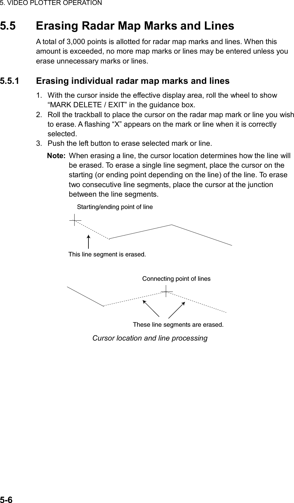
![5. VIDEO PLOTTER OPERATION 5-7 [DATA ERASE] 1 BACK 2 OWN TRACK 30%/50%/80%/ALL 3 TARGET TRACK 30%/50%/80%/ALL 4 MARK ALL ERASE 5 WPT ALL ERASE 6 NAV LINE ALL ERASE 5.5.2 Erasing all radar map marks and lines You can erase all radar map marks and lines from the screen as below. Be absolutely sure you want to erase all map marks and lines – erased marks and lines cannot be restored. 1. Roll the trackball to choose the MENU box at the right side of the screen and then push the left button. 2. Roll the wheel to choose 5 PLOTTER and then push the wheel or the left button. 3. Roll the wheel to choose 8 [DATA ERASE] and then push the wheel or the left button. DATA ERASE menu 4. Roll the wheel to choose 4 MARK ALL ERASE. 5. Push the wheel or the left button to erase all marks. 6. Push the right button three times to close the menu.](https://usermanual.wiki/Furuno-USA/9ZWRTR078/User-Guide-356443-Page-181.png)
![5. VIDEO PLOTTER OPERATION 5-8 [PLOTTER MENU] 1 BACK 2 CHART COLOR GRN/YEL/CYA ORANGE/GRAY 3 OWN TRACK INTERVAL OFF/10SEC/30SEC/ 1MIN/2MIN/3MIN/6MIN 4 OWN TRACK COLOR RED/GRN/BLU/YEL/ CYA/MAG/WHT 5 TARGET TRACK INTERVAL 10SEC/30SEC/1MIN/ 2 MIN/3MIN/6MIN 6 TARGET TRACK COLOR RED/GRN/BLU/YEL/ CYA/MAG/WHT 7 CURSOR L/L ALIGN OFF/ON 8 [DATA ERASE] 9 [DISPLAY] 5.6 Radar Map Corrections 5.6.1 Radar map correction When there is positional error between the radar screen and radar map marks and lines, do the following to correct it. 1. With the cursor inside the effective display area, roll the wheel to display “CHART ALIGN L=OFF / EXIT” in the guidance box. 2. Operate the trackball to align the radar map with the radar screen. 3. Push the left button to set. “MAN ALIGNED” appears at the right side of the screen. To release the radar map correction, display “CHART ALIGN L=OFF / EXIT” in the guidance box and then push the left button until “MAN ALIGNED” disappears from the screen. 5.6.2 Cursor data correction You can correct cursor data as below. 1. Roll the trackball to choose the MENU box at the right side of the screen and then push the left button. 2. Roll the wheel to choose 5 PLOTTER and then push the wheel or the left button. PLOTTER menu 3. Roll the wheel to choose 7 CURSOR L/L ALIGN and then push the wheel or the left button.](https://usermanual.wiki/Furuno-USA/9ZWRTR078/User-Guide-356443-Page-182.png)
![5. VIDEO PLOTTER OPERATION 5-94. Roll the wheel to choose ON and then push the wheel or the left button. “ALIGN” appears (in red) next to cursor position in the text area. (To remove the correction, choose OFF. If you are using the AIS function, choose ON.) 5. Push the right button twice to close the menu. 5.7 Chart Cards Charts may be overlaid on the radar image when the radar is interfaced with the optional Card I/F Unit CU-100. CAUTIONHandle chart cards and memory cardswith care. Keep cards away from direct sunlight, heat sources, and active gases. Keep cards away from water and chemicals. Keep the connector free foreign material. Do not drop the cards.Chart cards are intended as an aid to navigation. The navigator has the responsibility to check all aids availableto confirm position. 5.7.1 Displaying a chart To display a chart: 1. Insert a chart card in either of the two card slots in the Card I/F Unit CU-100. Card Slot Card slot location 2. Press the [POWER] button on the control unit to turn the power on. With the radar in transmit status, choose the radar display NU, CU, TM modes only) or the radar/video plotter display to display the chart. To display a chart after the power has been turned on, change the range by pressing the [RANGE+] or [RANGE-] key or operating the RANGE box.](https://usermanual.wiki/Furuno-USA/9ZWRTR078/User-Guide-356443-Page-183.png)
![5. VIDEO PLOTTER OPERATION 5-10 [PLOTTER MENU] 1 BACK 2 CHART COLOR GRN/YEL/CYA ORANGE/GRAY 3 OWN TRACK INTERVAL OFF/10SEC/30SEC/ 1MIN/2MIN/3MIN/6MIN 4 OWN TRACK COLOR RED/GRN/BLU/YEL/ CYA/MAG/WHT 5 TARGET TRACK INTERVAL 10SEC/30SEC/1MIN/ 2 MIN/3MIN/6MIN 6 TARGET TRACK COLOR RED/GRN/BLU/YEL/ CYA/MAG/WHT 7 CURSOR L/L ALIGN OFF/ON 8 [DATA ERASE] 9 [DISPLAY] 5.7.2 Chart position correction There may be a case where the chart overlay is not aligned with the radar image. This is due to an error in the position fixing system (GPS, Loran, etc.) or the different coordinates between the position fixing system and the radar. In this case, align the chart with the radar image as below. 1. With the cursor inside the effective display area, roll the wheel to display “CHART ALIGN L=OFF / EXIT” in the guidance box. 2. Operate the trackball to align the chart with the radar map. Note that track is neither recorded nor displayed at this point. 3. Push the left button to set. “ALIGN” appears (in red) at the right side of the screen. To release the chart position correction, display “CHART ALIGN L=OFF / EXIT” in the guidance box and then push the left button until “MAN ALIGNED” disappears from the screen. 5.7.3 Correcting cursor data 1. Roll the trackball to choose the MENU box at the right side of the screen and then push the left button. 2. Roll the wheel to choose 5 PLOTTER and then push the left button. PLOTTER menu 3. Roll the wheel to choose 7 CURSOR L/L ALIGN and then push the wheel or the left button. 4. Roll the wheel to choose ON and then push the wheel or the left button. “ALIGN” appears (in red) next to cursor position in the text area. (To remove the correction, choose OFF. If you are using the AIS function, choose ON.) 5. Push the right button twice to close the menu.](https://usermanual.wiki/Furuno-USA/9ZWRTR078/User-Guide-356443-Page-184.png)
![5. VIDEO PLOTTER OPERATION 5-11 [PLOTTER MENU] 1 BACK 2 CHART COLOR GRN/YEL/CYA ORANGE/GRAY 3 OWN TRACK INTERVAL OFF/10SEC/30SEC/ 1MIN/2MIN/3MIN/6MIN 4 OWN TRACK COLOR RED/GRN/BLU/YEL/ CYA/MAG/WHT 5 TARGET TRACK INTERVAL 10SEC/30SEC/1MIN/ 2 MIN/3MIN/6MIN 6 TARGET TRACK COLOR RED/GRN/BLU/YEL/ CYA/MAG/WHT 7 CURSOR L/L ALIGN OFF/ON 8 [DATA ERASE] 9 [DISPLAY] 5.7.4 Chart land color You may choose the color for the land on charts as follows: 1. Roll the trackball to choose the MENU box at the right side of the screen and then push the left button. 2. Roll the wheel to choose 5 PLOTTER and then push the left button. PLOTTER menu 3. Roll the wheel to choose 2 CHART COLOR and then push the left button or the wheel. 4. Choose color desired and push the wheel or the left button. 5. Push the right button twice to close the menu.](https://usermanual.wiki/Furuno-USA/9ZWRTR078/User-Guide-356443-Page-185.png)
![5. VIDEO PLOTTER OPERATION 5-12 5.8 Hiding/Showing Graphics on the Video Plotter Display 1. Roll the trackball to choose the MENU box at the right side of the screen and then push the left button. 2. Roll the wheel to choose 5 PLOTTER and then push the wheel or the left button. 3. Roll the wheel to choose 9 [DISPLAY] and then push the wheel or the left button. Roll the wheel to choose an item and then push the wheel or the left button. To go to page 2, choose 0 NEXT and then push the wheel or the left button. You may return to page 1 by choosing 1 BACK and pressing the wheel or the left button. [DISPLAY (1/2)] 1 BACK 2 GRID OFF/ON 3 OWN TRACK OFF/ON 4 TARGET TRACK OFF/ON 5 MARK OFF/ON 6 LAND DENSITY OFF/ON 7 PLACE NAME OFF/ON 8 COAST LINE OFF/ON 9 CONTOUR LINE OFF/ON 0 NEXT [DISPLAY (2/2)] 1 BACK 2 NAV LINE(MAP) OFF/ON 3 DANGER HIGHLIGHT OFF/ON 4 PROHIBITED AREA OFF/ON 5 BUOY OFF/ON Page 1Page 2Choose0 NEXTto showpage 2. DISPLAY menus 4. Push the wheel to choose OFF or ON as appropriate. Note: LAND DENSITY fills (ON) or hollows (OFF) land on an electronic chart. Land will be hollow when wrong card or wrong scale is used, regardless of LAND DENSITY setting. 5. Repeat steps 3 and 4 to set other items. 6. Push the right button three or four times to close the menu depending on which page of the DISPLAY menu you are using.](https://usermanual.wiki/Furuno-USA/9ZWRTR078/User-Guide-356443-Page-186.png)
![5. VIDEO PLOTTER OPERATION 5-13 [PLOTTER MENU] 1 BACK 2 CHART COLOR GRN/YEL/CYA ORANGE/GRAY 3 OWN TRACK INTERVAL OFF/10SEC/30SEC/ 1MIN/2MIN/3MIN/6MIN 4 OWN TRACK COLOR RED/GRN/BLU/YEL/ CYA/MAG/WHT 5 TARGET TRACK INTERVAL 10SEC/30SEC/1MIN/ 2 MIN/3MIN/6MIN 6 TARGET TRACK COLOR RED/GRN/BLU/YEL/ CYA/MAG/WHT 7 CURSOR L/L ALIGN OFF/ON 8 [DATA ERASE] 9 [DISPLAY] 5.9 Track 5.9.1 Plotting own ship’s track A total of 6,000 points are allotted for storage of own ship’s track, marks and lines. When this memory becomes full, the oldest track is deleted to make room for the latest. For that reason you may want to adjust the recording interval to conserve the memory. The table below shows the relation between plotting interval and maximum track recording time. Own track plotting interval and storage time Interval Max. Recording Time Interval Max. Recording Time10 s 55 hr 30 min 2 min 27 days 18 hr 40 min 30 s 166 hr 40 min 3 min 41 days 16 hr 1 min 13 days 21 hr 20 min 6 min 83 days 8 hr 1. Roll the trackball to choose the MENU box at the right side of the screen and then push the left button. 2. Roll the wheel to choose 5 PLOTTER and then push the wheel or the left button. PLOTTER menu 3. Roll the wheel to choose 3 OWN TRACK INTERVAL and then push the wheel or the left button. 4. Roll the wheel to choose appropriate track plotting interval and then push the wheel or the left button. Choose OFF to stop plotting own ship’s track. 5. Push the right button twice to close the menu.](https://usermanual.wiki/Furuno-USA/9ZWRTR078/User-Guide-356443-Page-187.png)
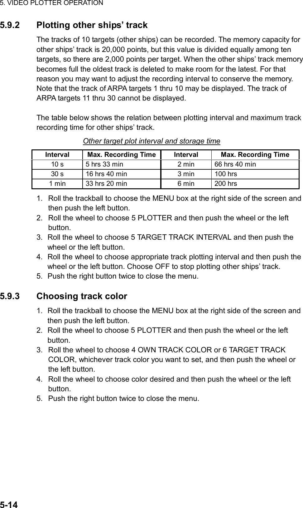
![5. VIDEO PLOTTER OPERATION 5-15 [DATA ERASE] 1 BACK 2 OWN TRACK 30%/50%/80%/ALL 3 TARGET TRACK 30%/50%/80%/ALL 4 MARK ALL ERASE 5 WPT ALL ERASE 6 NAV LINE ALL ERASE 5.9.4 Erasing track The display may become full of track when, for example, own ship traces the same route several times or there are many tracks from other ships. You can erase all or a percentage of your track or other tracks to clear the display. 1. Roll the trackball to choose the MENU box at the right side of the screen and then push the left button. 2. Roll the wheel to choose 5 PLOTTER and then push the wheel or the left button. 3. Roll the wheel to choose 8 [DATA ERASE] and then push the wheel or the left button. DATA ERASE menu 4. Roll the wheel to choose 2 OWN TRACK or 3 TARGET TRACK, whichever track you want to erase, and then push the wheel or the left button. 5. Roll the wheel to choose the percentage of track to erase and then push the wheel or the left button. For example, “30” erases the oldest 30% of the track selected at step 4. Choose “ALL” to erase all of the corresponding track. 6. Push the right button three times close the menu.](https://usermanual.wiki/Furuno-USA/9ZWRTR078/User-Guide-356443-Page-189.png)
![5. VIDEO PLOTTER OPERATION 5-16 [MARK MENU] 1 ORIGIN MARK STAB GND/SEA 2 ORIGIN MARK(No.)/ ORIGIN MARK(SYMBOL)/ MAP MARK/ WP 1~50/ WP 51~100/ WP 101~150/ WP 151~200/ OWN SHIP SHAPE 9 MAP DISPLAY OFF/ON 0 MAP MARK COLOR* RED/GRN/BLU/YEL/ CYA/MAG/WHT 5.10 Marks and Lines You can inscribe marks on the display to denote important points, for example, a buoy or a wreck. The memory for marks, lines and own ship’s track is 6,000 points. 5.10.1 Inscribing marks and lines 1. Roll the trackball to choose the MARK box at the left side of the screen. MARK >Mark type > +162.5 T 11.7NMBearing and range fromown ship to mark Mark box 2. Push the right button to open the MARK menu. MARK menu 3. Roll the wheel to choose “2” and then push the wheel or the left button. 4. Roll the wheel to choose MAP MARK and then push the wheel or the left button. 5. Push the right button to close the menu. The guidance box now reads “MARK SELECT / MARK MENU.” *: Not available on IMO radar.](https://usermanual.wiki/Furuno-USA/9ZWRTR078/User-Guide-356443-Page-190.png)
![5. VIDEO PLOTTER OPERATION 5-17 [PLOTTER MENU] 1 BACK 2 CHART COLOR GRN/YEL/CYA ORANGE/GRAY 3 OWN TRACK INTERVAL OFF/10SEC/30SEC/ 1MIN/2MIN/3MIN/6MIN 4 OWN TRACK COLOR RED/GRN/BLU/YEL/ CYA/MAG/WHT 5 TARGET TRACK INTERVAL 10SEC/30SEC/1MIN/ 2 MIN/3MIN/6MIN 6 TARGET TRACK COLOR RED/GRN/BLU/YEL/ CYA/MAG/WHT 7 CURSOR L/L ALIGN OFF/ON 8 [DATA ERASE] 9 [DISPLAY] 6. With the MARK box selected, roll the wheel to choose mark desired and then push the left button. The illustration below shows the plotter marks available. NAVLINECOASTLINECONTOURLINEPROHIBITEDAREASCABLE Plotter marks 7. Push the left button again. The cursor jumps into the effective display area and the guidance box reads “MARK / EXIT.” 8. Roll the trackball to place the cursor where you want to inscribe a mark and then push the left button to inscribe the mark. (You can see the range and bearing to the cursor location by monitoring the mark range and bearing indication just below the MARK box.) • To continue inscribing the same mark, repeat step 8. • To enter a different mark, push the right button when the guidance box reads “MARK / EXIT” and then do steps 6-8. (“MAP MARK” should be chosen on the MARK menu beforehand.) • To quit entering marks, push the right button when the guidance box reads “MARK / EXIT”. 5.10.2 Choosing mark color 1. Roll the trackball to choose the MENU box at the right side of the screen and then push the left button. 2. Roll the wheel to choose 5 PLOTTER and then push the wheel or the left button. PLOTTER menu](https://usermanual.wiki/Furuno-USA/9ZWRTR078/User-Guide-356443-Page-191.png)
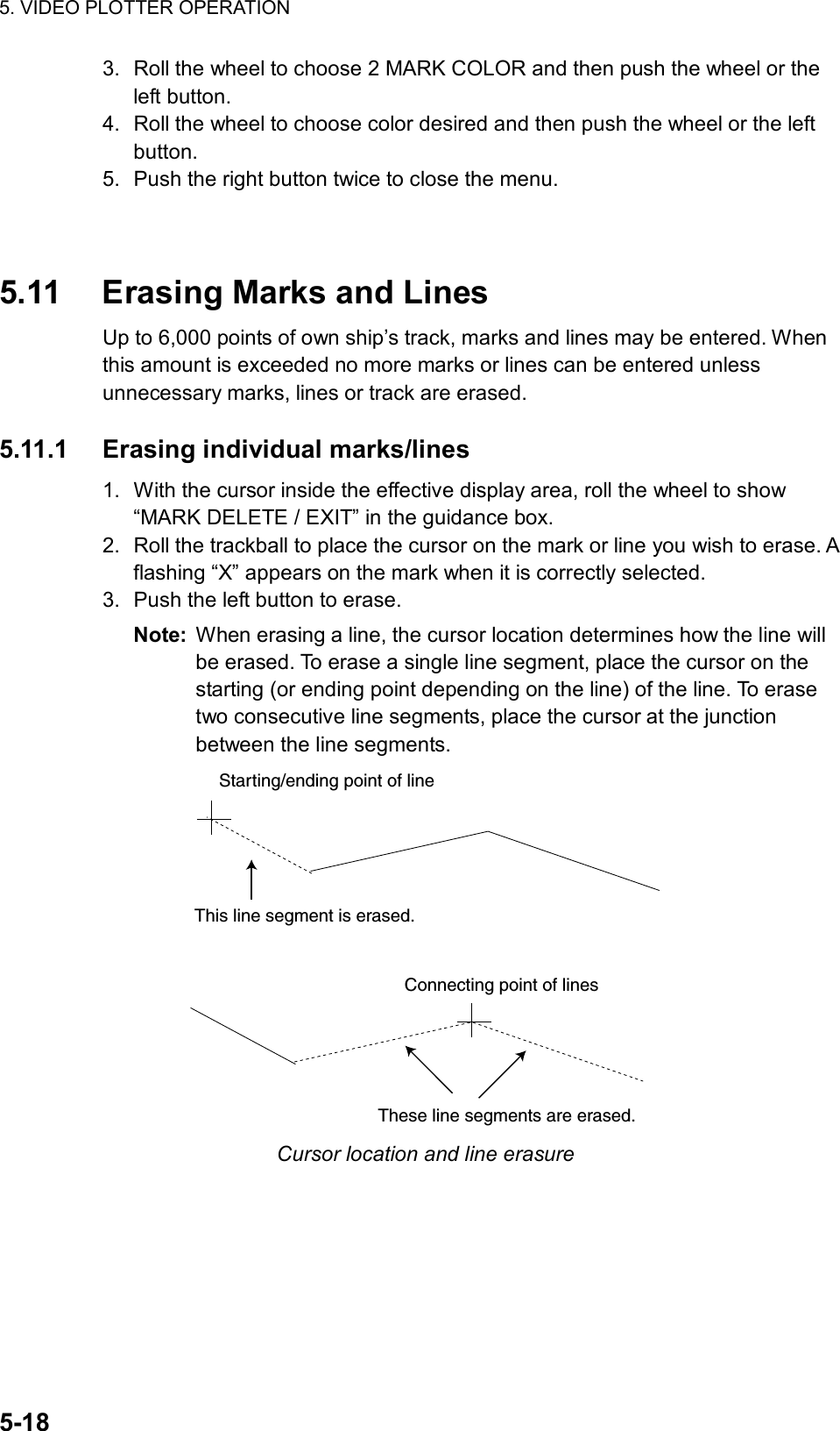
![5. VIDEO PLOTTER OPERATION 5-19 [DATA ERASE] 1 BACK 2 OWN TRACK 30%/50%/80%/ALL 3 TARGET TRACK 30%/50%/80%/ALL 4 MARK ALL ERASE 5 WPT ALL ERASE 6 NAV LINE ALL ERASE 5.11.2 Erasing all marks and lines To erase all plotter marks and lines from the memory, follow the procedure below. 1. Roll the trackball to choose the MENU box at the right side of the screen and then push the left button. 2. Roll the wheel to choose 5 PLOTTER and then push the wheel or the left button. 3. Roll the wheel to choose 8 [DATA ERASE] and then push the wheel or the left button. DATA ERASE menu 4. Roll the wheel to choose 4 MARK ALL ERASE. 5. Push the wheel or the left button to erase all plotter-related marks and lines. 6. Push the right button three times to close the menu.](https://usermanual.wiki/Furuno-USA/9ZWRTR078/User-Guide-356443-Page-193.png)
![5. VIDEO PLOTTER OPERATION 5-20 [MARK MENU] 1 ORIGIN MARK STAB GND/SEA 2 ORIGIN MARK(No.)/ ORIGIN MARK(SYMBOL)/ MAP MARK/ WP 1~50/ WP 51~100/ WP 101~150/ WP 151~200/ OWN SHIP SHAPE 9 MAP DISPLAY OFF/ON 0 MAP MARK COLOR* RED/GRN/BLU/YEL/ CYA/MAG/WHT 5.12 Waypoints A particular location is known as a “waypoint,” whether it be a starting point, a destination point or an intermediate point on a voyage. This unit can store 200 waypoints, numbered 001 to 200. Waypoints may be entered with the cursor or by input of latitude and longitude. 5.12.1 Entering waypoints Entering waypoints with the cursor 1. Roll the trackball to choose the MARK box at the left side of the screen. MARK >Mark type lastselected, marknumber> +162.5 T 11.7NMBearing and range from own ship to waypoint1 MARK box 2. Push the right button to open the MARK menu. MARK menu 3. Roll the wheel to choose “2” and then push the wheel. 4. Roll the wheel to choose the WPT item which best matches the waypoint number you wish to enter and then push the wheel or the left button. For example, if you want to enter waypoint number 59, choose “WPT 51-100.” 5. Push the right button to close the menu. The guidance box now reads “MARK SELECT / MARK MENU.” 6. With the MARK box selected, roll the wheel to display waypoint number desired and then push the left button. *: Not available on IMO radar.](https://usermanual.wiki/Furuno-USA/9ZWRTR078/User-Guide-356443-Page-194.png)
![5. VIDEO PLOTTER OPERATION 5-21 [NAV LINE•WPT (1/2)] 1 BACK 2 NAV LINE DATA SOURCE OFF/EXT DATA/ INTERNAL DATA/ WPT MARK 3 NAV LINE SELECT - - 4 ARRIVAL WPT ALARM OFF/ON 0.00NM 5 NAV LINE WIDTH 0.0NM 6 [WPT SET] 7 [WPT LIST] 8 [NAV LINE SET] 9 [NAV LINE LIST] 0 NEXT 7. Push the left button again. The cursor jumps into the effective display area and the guidance box reads “MARK / EXIT.” 8. Roll the trackball to place the cursor where you want to inscribe a waypoint mark and then push the left button to inscribe the mark. The waypoint mark (“ ” + waypoint number) appears at the location selected. (You can see the range and bearing to the cursor location by monitoring the mark range and bearing indication just below the MARK box.) • To enter another waypoint, push the right button when the guidance box reads “MARK / EXIT” and then repeat steps 6-8. (“WPT” should be chosen on the MARK menu.) • To quit entering waypoints, push the right button when the guidance box reads “MARK / EXIT.” Entering waypoints by manual input of latitude and longitude 1. Roll the trackball to choose the MENU box at the right side of the screen and then push the left button. 2. Roll the wheel to choose 8 [NAV LINE•WPT] and then push the wheel or the left button. NAV LINE•WPT menu](https://usermanual.wiki/Furuno-USA/9ZWRTR078/User-Guide-356443-Page-195.png)
![5. VIDEO PLOTTER OPERATION 5-22 [WPT SET] 1 BACK 2 WPT NO. SELECT 000 3 WPT NAME 4 WPT L/L 00°00.000 N 000°00.000 E 5 CLEAR DATA 3. Roll the wheel to choose 6 [WPT SET] and then push the wheel or the left button. WPT SET menu 4. Roll the wheel to choose 2 WPT NO. SELECT and then push the wheel or the left button. 5. Use the wheel to choose waypoint number: Roll the wheel to choose location and then push the wheel to set. 6. To enter waypoint name, follow the procedure below. If you do not require waypoint name go to step 7. 1) Roll the wheel to choose 3 WPT NAME and then push the wheel or the left button. 2) Roll the wheel to choose alphanumeric character desired and then push the wheel. Rolling the wheel downward displays -, +, 0…9, a…z, A…Z, !, “, #, $, %, &, ‘, (, ), = ~, │,(comma) and .(period) in that order. 3) Repeat step 2 to complete the waypoint name. You may use up to 16 alphanumeric characters for waypoint name. 7. Roll the wheel to choose 4 WPT L/L and then push the wheel or the left button. 8. Enter latitude and longitude position as follows: 1) Roll the wheel to choose location desired and then push the wheel. (The wheel may be pushed again to skip a place.) For input by keyboard, press appropriate numeric keys and then press the [ENTER MARK] key. 2) To switch co-ordinate polarity, roll the wheel or use the [2] key in case of keyboard operation. 9. To enter another waypoint, repeat steps 4-8. 10. Push the right button three times to close the menu.](https://usermanual.wiki/Furuno-USA/9ZWRTR078/User-Guide-356443-Page-196.png)
![5. VIDEO PLOTTER OPERATION 5-23 [WPT SET] 1 BACK 2 WPT NO. SELECT 000 3 WPT NAME 4 WPT L/L 00°00.000 N 000°00.000 E 5 CLEAR DATA 5.12.2 Editing, erasing waypoints from the menu You may edit or erase waypoints from the menu as follows: 1. Roll the trackball to choose the MENU box at the right side of the screen and then push the left button. 2. Roll the wheel to choose 8 [NAV LINE•WPT] and then push the wheel or the left button. 3. Roll the wheel to choose 6 [WPT SET] and then push the wheel or the left button. WPT SET menu 4. Roll the wheel to choose 2 WPT NO. SELECT and then push the wheel or the left button. 5. Use the wheel to enter waypoint number you wish to edit and then push the wheel or the left button. Then, do one of the following: • To change the waypoint name, roll the wheel to choose 3 WPT NAME and then push the wheel or the left button. Use the wheel to edit waypoint name. • To edit the waypoint position, roll the wheel to choose 4 WPT L/L and then push the wheel or the left button. Use the wheel to edit waypoint position. • To erase the waypoint, roll the wheel to choose 5 CLEAR DATA and then push the wheel or the left button. 6. Push the right button three times to close the menu.](https://usermanual.wiki/Furuno-USA/9ZWRTR078/User-Guide-356443-Page-197.png)
![5. VIDEO PLOTTER OPERATION 5-24 [DATA ERASE] 1 BACK 2 OWN TRACK 30%/50%/80%/ALL 3 TARGET TRACK 30%/50%/80%/ALL 4 MARK ALL ERASE 5 WPT ALL ERASE 6 NAV LINE ALL ERASE 5.12.3 Erasing waypoints Waypoints may be erased individually or collectively. Erasing individual waypoints 1. With the cursor inside the effective display area, roll the wheel to display “MARK DELETE / EXIT” in the guidance box. 2. Roll the trackball to place the cursor on the waypoint you wish to erase. A flashing “X” appears on the mark when it is correctly selected. 3. Push the left button or the wheel to erase the waypoint. 4. To erase another waypoint, repeat steps 2 and 3. 5. To finish, push the right button when the guidance reads “MARK DELETE / EXIT”. Erasing all waypoints 1. Roll the trackball to choose the MENU box at the right side of the screen and then push the left button. 2. Roll the wheel to choose 5 PLOTTER and then push the wheel or the left button. 3. Roll the wheel to choose 8 [DATA ERASE] and then push the wheel or the left button. DATA ERASE menu 4. Roll the wheel to choose 5 WPT ALL ERASE. 5. Push the wheel or the left button to erase all waypoints. 6. Push the right button three times to close the menu.](https://usermanual.wiki/Furuno-USA/9ZWRTR078/User-Guide-356443-Page-198.png)
![5. VIDEO PLOTTER OPERATION 5-25 [WPT LIST (1/1)] 1 BACK 001 001 34°42.110 N 136°31.580 E 002 002 33°97.690 N 134°64.350 E 003 004 0 NEXT 5.12.4 Waypoint list The waypoint list stores position data of all registered waypoints. Each page of the waypoint list holds eight waypoints. To display the waypoint list: 1. Roll the trackball to choose the MENU box at the right side of the screen. 2. Roll the wheel to choose 8 NAV LINE•WPT and then push the wheel or the left button. 3. Roll the wheel to choose 7 [WPT LIST] and then push the wheel or the left button. Asterisks indicate no data. WPT list 4. To go to a next page, choose 0 NEXT and then push the wheel or the left button. 5. Push the right button several times to close the waypoint list and the menu.](https://usermanual.wiki/Furuno-USA/9ZWRTR078/User-Guide-356443-Page-199.png)
![5. VIDEO PLOTTER OPERATION 5-26 [NAV LINE•WPT (2/2)] 1 BACK 2 SKIP NEXT WPT 3 TURNING LINE OFF/ON/REVISED 4 DISP WPT NO. OFF/ON 5 DISP WPT NAME OFF/ON 5.12.5 Displaying waypoint name and number You may turn waypoint name and number display on or off as desired. 1. Roll the trackball to choose the MENU box at the right side of the screen and then push the left button. 2. Roll the wheel to choose 8 [NAV LINE•WPT] and then push the wheel or the left button. 3. Roll the wheel to choose 0 NEXT and then push the wheel or the left button. NAV LINE•WPT menu (2/2) 4. Roll the wheel to choose 4 DISP WPT NO. and then push the wheel or the left button. 5. Roll the wheel to choose OFF or ON as appropriate and then push the wheel or the left button. 6. Roll the wheel to choose 5 DISP WPT NAME and then push the wheel or the left button. 7. Roll the wheel to choose OFF or ON as appropriate and then push the wheel or the left button. 8. Push the right button three times to close the menu.](https://usermanual.wiki/Furuno-USA/9ZWRTR078/User-Guide-356443-Page-200.png)
![5. VIDEO PLOTTER OPERATION 5-27 [NAV LINE SET] 1 BACK 2 NAV LINE NO. SELECT 00 3 NAV LINE NAME 4 [NAV LINE ENTRY] 5 CLEAR DATA [NAV LINE ENTRY] 1 BACK 2 NAV LINE WPT — — — — — — — — — — — — — — — — — — — — — — — — — — — — — 0 BACK5.13 Nav Lines 30 nav lines may be entered, and each line may have up to 30 waypoints. 5.13.1 Entering new nav line To enter a nav line, first enter appropriate waypoints. Then, do the following: 1. Roll the trackball to choose the MENU box and then push the left button. 2. Roll the wheel to choose 8 [NAV LINE•WPT] and then push the wheel or the left button. 3. Roll the wheel to choose 8 [NAV LINE SET] and then push the wheel or the left button. NAV LINE SET menu 4. Roll the wheel to choose 2 NAV LINE NO. SELECT and then push the wheel or the left button. 5. Use the wheel to enter nav line no., in two digits. 6. Roll the wheel to choose 3 NAV LINE NAME and then push the wheel or the left button. 7. Use the wheel to enter a name. 8. Roll the wheel to choose 4 [NAV LINE ENTRY] and then push the wheel or left button. NAV LINE ENTRY display 9. Use the wheel to enter waypoint numbers, in three digits. Roll the wheel to choose numeral and push it to set.](https://usermanual.wiki/Furuno-USA/9ZWRTR078/User-Guide-356443-Page-201.png)
![5. VIDEO PLOTTER OPERATION 5-28 10. To enter another nav line, roll the wheel to choose 0 BACK to return to the NAV LINE SET menu and then repeat steps 4-9. 11. To finish, push the right button several times to close the menu. 5.13.2 Editing nav lines 1. Roll the trackball to choose the MENU box and then push the left button. 2. Roll the wheel to choose 8 [NAV LINE•WPT] and then push the wheel or the left button. 1. Roll the wheel to choose 8 [NAV LINE SET] and then push the wheel or the left button. 2. Roll the wheel to choose 2 NAV LINE NO. SELECT and then push the wheel or the left button. 3. Use the wheel to enter nav line number to edit and then push the wheel or the left button. 4. To edit nav line name, roll the wheel to choose 3 NAV LINE NAME and then push the wheel or the left button. Use the wheel to change name. 5. To replace waypoints in a nav line, do the following: 1) Roll the wheel to choose 4 [NAV DATA ENTRY] and then push the wheel or the left button. 2) Roll the wheel to choose 2 NAV LINE WPT and then push the wheel or the left button. 3) Push the wheel to choose the waypoint you wish to replace. 4) Roll the wheel to set new waypoint number. 5) Push the wheel to finish. 6. Push the right button several times to close the menu.](https://usermanual.wiki/Furuno-USA/9ZWRTR078/User-Guide-356443-Page-202.png)
![5. VIDEO PLOTTER OPERATION 5-29 [NAV LINE LIST (1/30)] 1 BACK 001—002—003 004—005—006 — — — — — — — — — — — — — — — — — — — — — — — — 0 NEXT 5.13.3 Nav line list The nav line list, which shows all nav lines registered, may be displayed as follows: 1. Roll the trackball to choose the MENU box and then push the left button. 2. Roll the wheel to choose 8 [NAV LINE•WPT] and then push the wheel or the left button. 3. Roll the wheel to choose 9 [NAV LINE LIST] and then push the wheel or the left button. NAV LINE LIST 4. To go to a next page choose 0 NEXT and then push the wheel or the left button. To return to a previous page, choose 1 BACK and then push the wheel or the left button. 5. Push the right button as many times as necessary to close the menu.](https://usermanual.wiki/Furuno-USA/9ZWRTR078/User-Guide-356443-Page-203.png)
![5. VIDEO PLOTTER OPERATION 5-30 [NAV LINE SET] 1 BACK 2 NAV LINE NO. SELECT 01 3 NAV LINE NAME 4 [NAV LINE ENTRY] 5 CLEAR DATA [DATA ERASE] 1 BACK 2 OWN TRACK 30%/50%/80%/ALL 3 TARGET TRACK 30%/50%/80%/ALL 4 MARK ALL ERASE 5 WPT ALL ERASE 6 NAV LINE ALL ERASE 5.13.4 Erasing nav lines 30 nav lines may be entered. You may erase unnecessary nav lines as shown below. A nav line which is currently in use cannot be erased. Erasing individual nav lines 1. Roll the trackball to choose the MENU box at the right side of the screen and then push the left button. 2. Roll the wheel to choose 8 [NAV LINE•WPT] and then push the wheel or the left button. 3. Roll the wheel to choose 8 [NAV LINE SET] and then push the wheel or the left button. NAV LINE SET menu 4. Roll the wheel to choose 2 NAV LINE NO. SELECT and then push the wheel or the left button. 5. Use the wheel to enter nav line no., in two digits. 6. Roll the wheel to choose 5 CLEAR DATA. 7. Push the wheel or the left button to delete the nav line. 8. Push the right button three times to close the menu. Erasing all nav lines 1. Roll the trackball to choose the MENU box and then push the left button. 2. Roll the wheel to choose 5 PLOTTER and then push the wheel or the left button. 3. Roll the wheel to choose 8 [DATA ERASE] and then push the wheel or the left button. DATA ERASE menu](https://usermanual.wiki/Furuno-USA/9ZWRTR078/User-Guide-356443-Page-204.png)
![5. VIDEO PLOTTER OPERATION 5-31 [NAV LINE•WPT (1/2)] 1 BACK 2 NAV LINE DATA SOURCE OFF/EXT DATA/ INTERNAL DATA/ WPT MARK 3 NAV LINE SELECT 00 4 ARRIVAL WPT ALARM OFF/ON 0.00NM 5 NAV LINE WIDTH 0.00NM 6 [WPT SET] 7 [WPT LIST] 8 [NAV LINE SET] 9 [NAV LINE LIST] 0 NEXT 4. Roll the wheel to choose 6 NAV LINE ALL ERASE. 5. Push the wheel or the left button to erase all nav lines and their data. 6. Push the right button three times to close the menu. 5.13.5 Setting up nav lines Nav lines can be set up as follows: 1. Roll the trackball to choose the MENU box and then push the left button. 2. Roll the wheel to choose 8 [NAV LINE•WPT] and then push the wheel or the left button. NAV LINE•WPT menu (1/2) 3. Roll the wheel to choose 2 NAV LINE DATA SOURCE and then push the wheel or the left button. 4. Roll the wheel to choose INTERNAL DATA and then push the wheel or the left button. 5. Roll the wheel to choose 5 NAV LINE WIDTH. 6. Use the wheel to enter the width for the nav line, from 0.0-9.9(nm). A pair of red lines mark the width of the nav line. 7. If you want to be alerted when own ship nears a waypoint by a preset distance, roll the wheel to choose 4 ARRIVAL WPT ALARM and then push the wheel or the left button. Push the wheel to choose ON. 8. Use the wheel to enter the arrival alarm range, in three digits.](https://usermanual.wiki/Furuno-USA/9ZWRTR078/User-Guide-356443-Page-205.png)
![5. VIDEO PLOTTER OPERATION 5-32 [NAV LINE•WPT (2/2)] 1 BACK 2 SKIP NEXT WPT 3 TURNING LINE OFF/ON/REVISED 4 DISP WPT NO. OFF/ON 5 DISP WPT NAME OFF/ON 9. Roll the wheel to choose 0 NEXT and then push the wheel or the left button. NAV LINE•WPT menu (2/2) 10. Roll the wheel to choose 3 TURNING LINE and then push the wheel or the left button. 11. Roll the wheel to choose appropriate option and then push the wheel or the left button. OFF: Turns turning lines off. ON: Use this setting when the vessel is not to correct cross track error to return to course set, after arriving at turning line location. REVISED: Use this setting when vessel is to return to course set after correcting cross track error, after arriving at turning line location. Own shipTurning lineCourseNavlineTr a ckTurning lineTURNING LINE: REVISEDTURNING LINE: ONNo cross track error correction at turning lineCross track error correction at turning line Turning line 12. Push the right button three times to close the menu.](https://usermanual.wiki/Furuno-USA/9ZWRTR078/User-Guide-356443-Page-206.png)
![5. VIDEO PLOTTER OPERATION 5-335.13.6 Displaying nav line, waypoint mark Displaying internal nav lines 1. Roll the trackball to choose the MENU box and then push the left button. 2. Roll the wheel to choose 8 [NAV LINE•WPT] and then push the wheel or the left button. 3. Roll the wheel to choose 2 NAV LINE DATA SOURCE and then push the wheel or the left button. 4. Roll the wheel to choose INTERNAL DATA and then push the wheel or the left button. 5. Roll the wheel to choose 2 NAV LINE SELECT and then push the wheel or the left button. 6. Use the wheel to enter the nav line number you want to display. Roll the wheel to choose numeral and push it to set. Note that the same nav line no. cannot be entered more than once. 7. To skip the next waypoint, roll the wheel to choose 2 SKIP NEXT WPT and then push the wheel or the left button. 8. Push the right button twice to close the menu. Displaying external nav lines Nav lines from an external navigator can be displayed as below. RTE and WPL sentences are necessary to display a nav line from a navigator. 1. Roll the trackball to choose the MENU box and then push the left button. 2. Roll the wheel to choose 8 [NAV LINE•WPT] and then push the wheel or the left button. 3. Roll the wheel to choose 2 NAV LINE DATA SOURCE and then push the wheel or the left button. 4. Roll the wheel to choose EXT DATA and then push the wheel or the left button. 5. Do the following as appropriate: 1) Set width (0.0-9.9 nm) of the nav line with 5 NAV LINE WIDTH. 2) Turn waypoint number display on or off with 4 DSP WPT NO (page 2 of NAV LINE•WPT menu). 3) Set turning line with 3 TURNING LINE (page 2 of NAV LINE•WPT menu). 6. Push the right button two or three times depending on which page of the NAV LINE•WPT menu you are using.](https://usermanual.wiki/Furuno-USA/9ZWRTR078/User-Guide-356443-Page-207.png)
![5. VIDEO PLOTTER OPERATION 5-34 Waypoint mark The waypoint mark shows the location of a destination waypoint which is set on a navigator. You may mark this location on the radar display by following the procedure shown below. 000 010 020030040050060070080090100110120130140150160170180190200210220230240250260270280290300310320330340 350Waypoint Mark Waypoint mark 1. Roll the trackball to choose the MENU box and then push the left button. 2. Roll the wheel to choose 8 [NAV LINE•WPT] and then push the wheel or the left button. 3. Roll the wheel to choose 2 NAV LINE DATA SOURCE and then push the wheel or the left button. 4. Roll the wheel to choose WPT MARK and then push the wheel or the left button. 5. Push the right button twice to close the menu.](https://usermanual.wiki/Furuno-USA/9ZWRTR078/User-Guide-356443-Page-208.png)
![5. VIDEO PLOTTER OPERATION 5-35 [CARD] 1 BACK 2 DRIVE SELECT A* 3 [READ CARD] 4 [WR MARK] 5 [WR WPT NAV LINE] 6 [WR OWN TRACK] 7 [WR TARGET TRACK] 8 [WR SETTING DATA] 9 [WR INSTALLATION DATA]0 NEXT 5.14 Recording Data The optional Card I/F Unit CU-100 is required to record or replay data. 5.14.1 Initializing memory (RAM) cards Before you can use a memory (RAM) card it must be initialized. Formatting prepares the recording surface of the card for use with the system, and deletes all data recorded in the memory card. You can format cards you’ve used before, however, in which case all prior information on them is erased. 1. Insert a blank memory card into the appropriate card slot in the Card I/F Unit. Card Slot Card I/F unit, front view 2. Roll the trackball to choose the MENU box and then push the left button. 3. Roll the wheel to choose 6 [CARD] and then push the wheel or the left button. (Note that “WR” in the CARD menu means “Write.”) CARD menu, page 1 4. Roll the wheel to choose 2 DRIVE SELECT and then push the wheel or the left button. 5. Roll the wheel to choose appropriate drive and then push the wheel or the left button. * Drives available are shown.](https://usermanual.wiki/Furuno-USA/9ZWRTR078/User-Guide-356443-Page-209.png)
![5. VIDEO PLOTTER OPERATION 5-36 [CARD] 1 BACK 2 DRIVE SELECT A 3 [READ CARD] 4 [WR MARK] 5 [WR WPT NAV LINE] 6 [WR OWN TRACK] 7 [WR TARGET TRACK] 8 [WR SETTING DATA] 9 [WR INSTALLATION DATA]0 NEXT 6. Roll the wheel to choose 0 NEXT and then push the wheel or the left button. CARD menu, page 2 5. Roll the wheel to choose 3 CARD INITIALIZE and then push the wheel or the left button. CARD INITIALIZE menu 6. Roll the wheel to choose 2 INITIALIZE START and then push the wheel or the left button to initialize the card. 7. After the card has been initialized, push the right button three times to close the menu. 5.14.2 Recording data When the memory becomes full, the oldest track is erased to make room for the latest. Further, when the memory is full you cannot enter another mark or line unless you erase unnecessary marks, lines or track. Thus you should save important data to a memory card so as not to lose important data. 1. Insert initialized memory card into appropriate drive in Card I/F Unit. 2. Roll the trackball to choose the MENU box and then push the left button. 3. Roll the wheel to choose 6 [CARD] and then push the wheel or the left button. CARD menu 4. Roll the wheel to choose DRIVE SELECT and then push the wheel or the left button. [CARD] 1 BACK 2 [FILE DELETE] 3 [CARD INITIALIZE] [CARD INITIALIZE] 1 BACK 2 INITIALIZE START](https://usermanual.wiki/Furuno-USA/9ZWRTR078/User-Guide-356443-Page-210.png)
![5. VIDEO PLOTTER OPERATION 5-375. Roll the wheel to choose appropriate drive and then push the wheel or the left button. 6. Roll the wheel to choose data to record (one item among 4-9) and then push the wheel or the left button. For example choose 4 WR MARK and then push the wheel or the left button. The display then looks something like the one below. CARD WRITE menu Note: The file name is composed of a single alphabet, the file type, and seven digits, the file number. The file type is denoted as follows: R: Mark W: Waypoint, nav line T: Own track A: Target track S: Setting data I: Installation data 7. Use the wheel and the left button to enter file title. You may use up to seven digits. 8. After entering the last digit of the file name the chosen item is recorded. [WR MARK] 1 BACK 2 NAME (See note below.) R0000000](https://usermanual.wiki/Furuno-USA/9ZWRTR078/User-Guide-356443-Page-211.png)
![5. VIDEO PLOTTER OPERATION 5-38 [CARD] 1 BACK 2 DRIVE SELECT A 3 [READ CARD] 4 [WR MARK] 5 [WR WPT NAV LINE] 6 [WR OWN TRACK] 7 [WR TARGET TRACK] 8 [WR SETTING DATA] 9 [WR INSTALLATION DATA]0 NEXT 5.15 Replaying Data Video plotter data (track, marks, etc.) may be replayed on the screen. This is useful for analyzing past data. 1. Insert memory card into the appropriate slot in an I/F card unit. 2. Roll the trackball to choose the MENU box and then push the left button. 3. Roll the wheel to choose 6 [CARD] and then push the wheel or the left button. CARD menu 4. Roll the wheel to choose 2 DRIVE SELECT and then push the wheel or the left button. 5. Roll the wheel to choose the drive where you inserted the memory card. 6. Push the wheel or the left button. 7. Roll the wheel to choose 3 READ CARD and push the wheel or the left button. READ CARD menu 8. Roll the wheel to choose the data to replay. 9. Push the wheel or the left button to replay chosen data. 10. After the data has been replayed, push the right button twice to close the menu. [READ CARD] 1 BACK 2 NAME T200304109 . . . 9 NAME R200307318 0 NEXT](https://usermanual.wiki/Furuno-USA/9ZWRTR078/User-Guide-356443-Page-212.png)
![5. VIDEO PLOTTER OPERATION 5-395.16 Deleting Files 1. Roll the trackball to choose the MENU box and then push the left button. 2. Roll the wheel to choose 6 [CARD] and then push the wheel or the left button. 3. Roll the wheel to choose 2 DRIVE SELECT and then push the wheel or the left button. 4. Roll the wheel to choose the appropriate drive and then push the wheel or the left button. 5. Roll the wheel to choose 0 NEXT and then push the wheel or the left button. CARD menu, page 2 6. Roll the wheel to choose 2 FILE DELETE and then push the wheel or the left button. FILE DELETE display 7. Roll the wheel to choose the file to delete and then push the wheel or the left button. 8. Push the right button three times to close the menu. [CARD] 1 BACK 2 FILE DELETE 3 CARD INITIALIZE [FILE DELETE] 1 BACK 2 T2003410 3 W2003126 4 A20035311 5 S20030129 6 S20030118 7 8 9 0 NEXT](https://usermanual.wiki/Furuno-USA/9ZWRTR078/User-Guide-356443-Page-213.png)
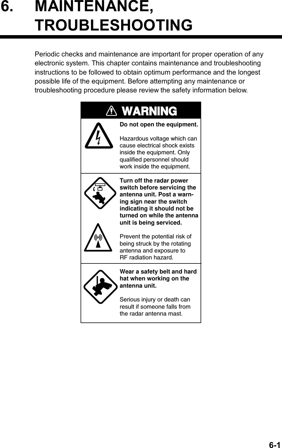
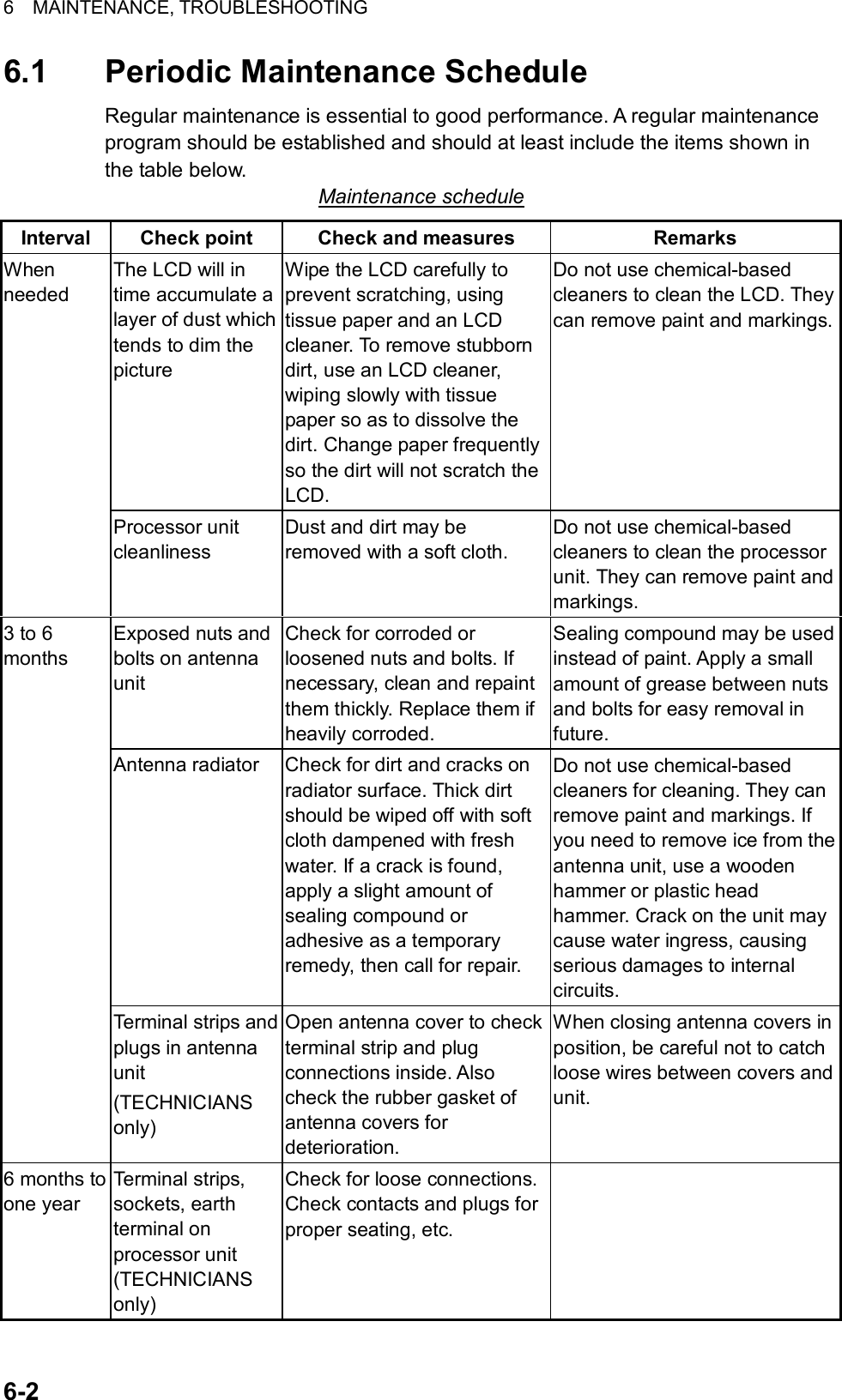
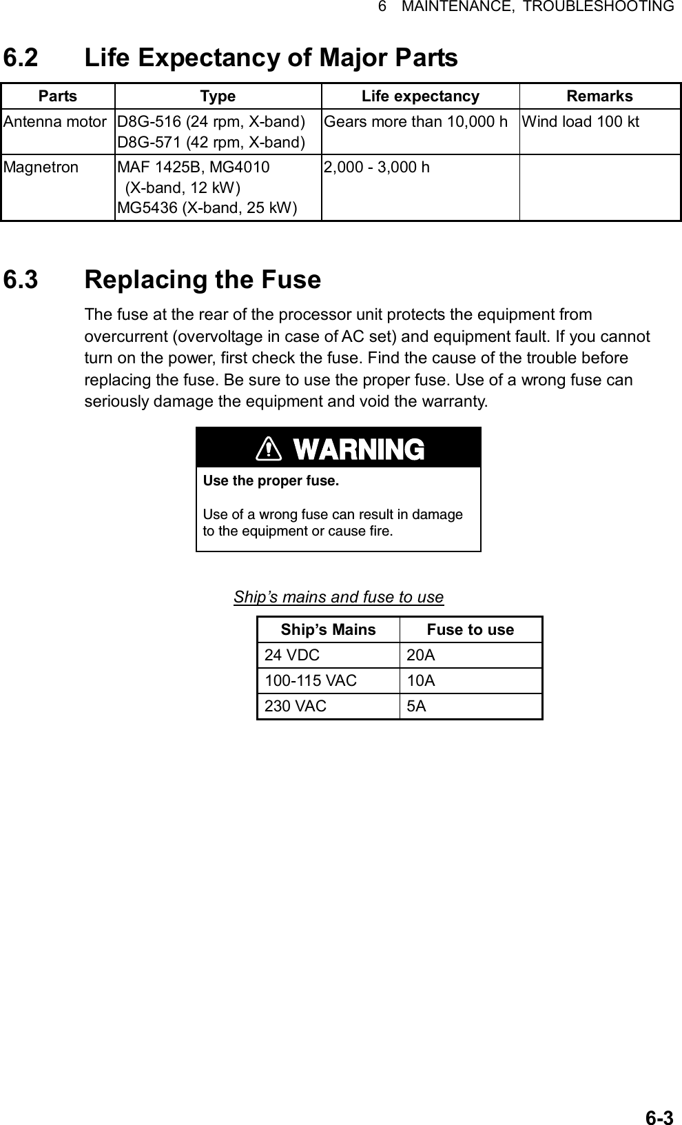
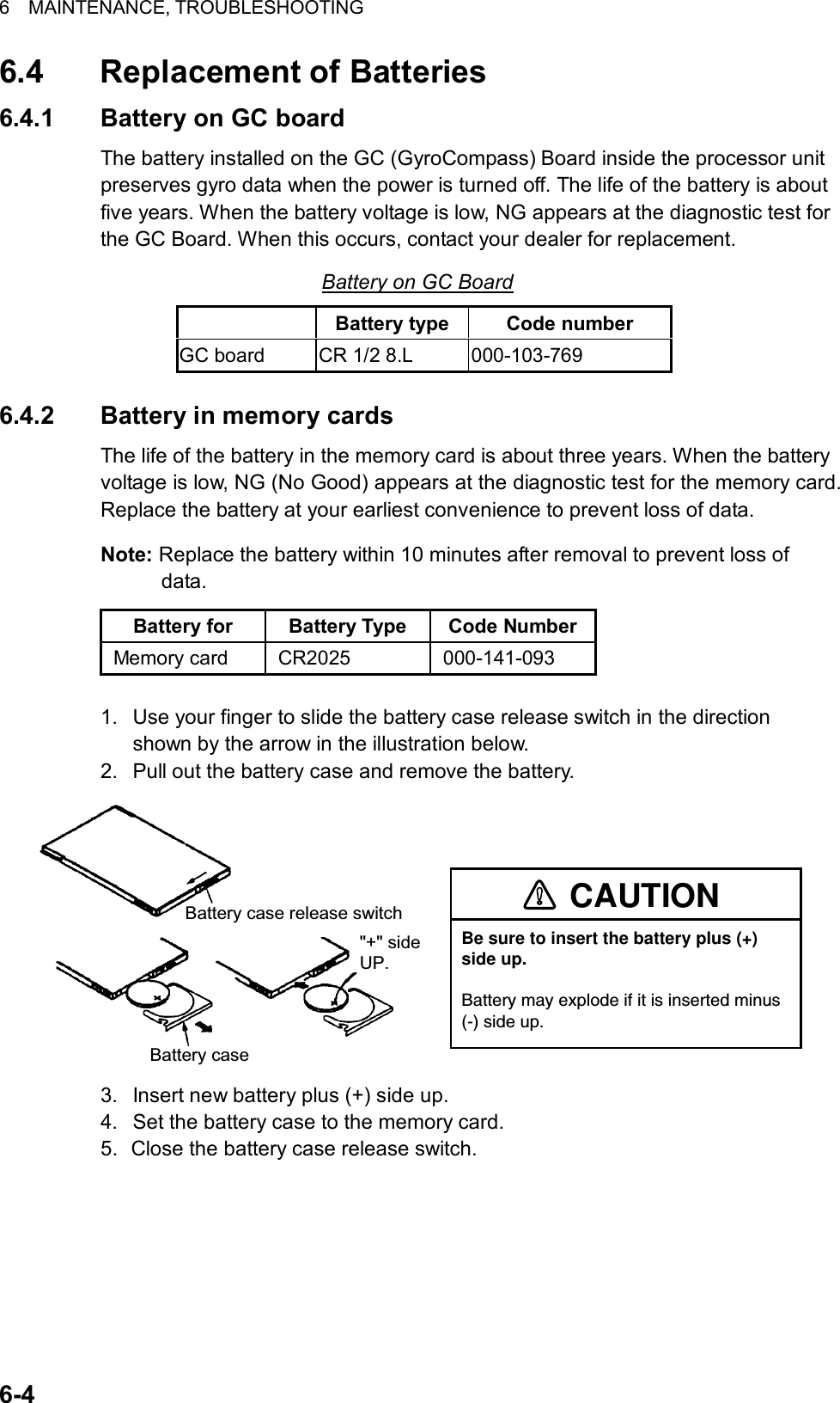
![6 MAINTENANCE, TROUBLESHOOTING 6-56.5 Easy Troubleshooting This paragraph provides troubleshooting procedures which the user may follow to restore normal operation. If you cannot restore normal operation, do not attempt to check inside any unit. Any repair work is best left to a qualified technician. Easy troubleshooting procedures Problem Cause Remedy Key beep inaudible Key beep turned off Adjust key beep level on the OPERATION menu, referring to paragraph 1.42. Picture not updated or picture freeze-up Video freeze-up Turn the power off and on again to restore normal operation. Marks, indications and noise appear but no echo Blown fuse Check for blown fuse in processor unit. Range changed but radar picture does not change Defective range key or video freeze up Try to hit RANGE [+] and [-] range keys (or RANGE box) several times. (If unsuccessful, replacement of keypad may be required in case of the keyboard-type control unit.) If that does not work try to turn the power off and on again to see if the problem might be video freeze up. Only 2 parallel index lines when 6 lines are wanted Incorrect setting of index line intervals Incorrect setting of index line intervals. Adjust index line interval, referring to paragraph 1.29.2. Also, the setting for number of index of lines to display may be inappropriate. Check the menu setting for number of index lines, referring to paragraph 1.29.4. Range rings are not displayed Range rings turned off Try turning on the range rings with 0 RINGS in the MARK menu. If they do not appear, their brilliance may be too low. Adjust their brilliance at page 1 of the BRILL menu. ARPA target not tracked correctly Poor definition of targets in sea clutterAdjust A/C SEA and A/C RAIN referring to paragraph 1.17 and 1.18. Tuning adjusted but poor sensitivity 2nd trace echo rejector on or dirt on radiator face • Turn off the 2nd trace echo rejector, referring to paragraph 1.37. • Clean the radiator face.](https://usermanual.wiki/Furuno-USA/9ZWRTR078/User-Guide-356443-Page-219.png)
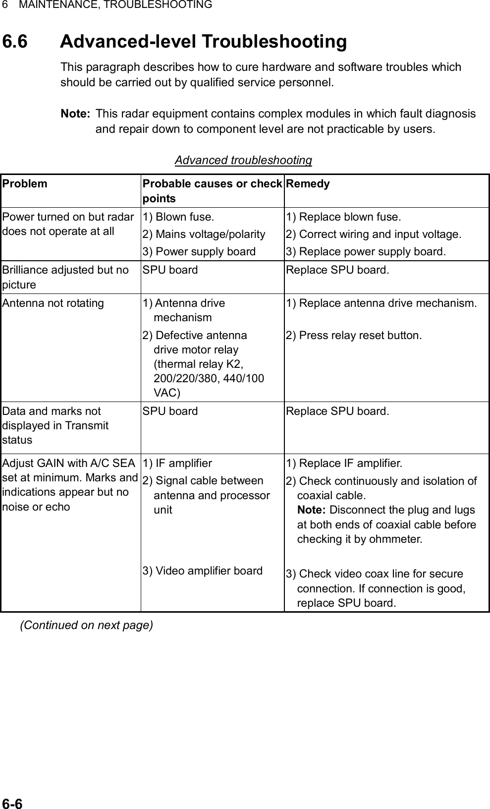
![6 MAINTENANCE, TROUBLESHOOTING 6-7Advanced troubleshooting (con’t) Problem Probable causes or check points Remedy Marks, indications and noise appear but no echo (Transmission leak representing own ship position is absent) 1) TX fuse 2) Magnetron 3) Modulator board 4) SPU board 1) If fuse is blown, replace it. If it blowsagain, the modulator or associated circuit may be defective. 2) Check magnetron current. Replace magnetron. 3) Replace modulator board. 4) Replace SPU board. Picture not updated or picture freeze-up 1) Bearing signal generator board (in antenna unit) 2) SPU board 3) Video freeze-up 1) Check the connection of signal cables. 2) Replace SPU board. 3) Turn off and on the radar. Incorrect orientation of picture 1) SPU board 2) Gyro interface 1) The message HDG SIG MISSING appears when the heading pulse is not received during standby. 2) Replace the gyro interface. Cannot operate radar from on-screen boxes SPU Board Replace SPU Board. Radar is properly tuned but poor sensitivity 1) Deteriorated magnetron 2) Detuned MIC 3) Dirt on radiator face 4) Water ingress to the waveguide or other feeder line 5) Second trace echo rejection is ON 1) With the radar transmitting on 48 nmrange, check magnetron current. If current is below normal, magnetron may be defective. Replace it. 2) Check MIC detecting current. If it is below normal value, MIC may have become detuned. MIC must be tuned. 3) Clean the radiator surface. 4) Remove water from the feeder line. 5) Disable the second-trace echo rejector referring to paragraph 1.37. Range changed but radar picture not changing 1) Defective range key 2) SPU board 3) Video freeze-up 1) Try to hit RANGE [+] and [-] keys several times. If unsuccessful, replacement of keypad may be required. 2) Replace SPU board. 3) Turn off and on radar. (Continued on next page)](https://usermanual.wiki/Furuno-USA/9ZWRTR078/User-Guide-356443-Page-221.png)
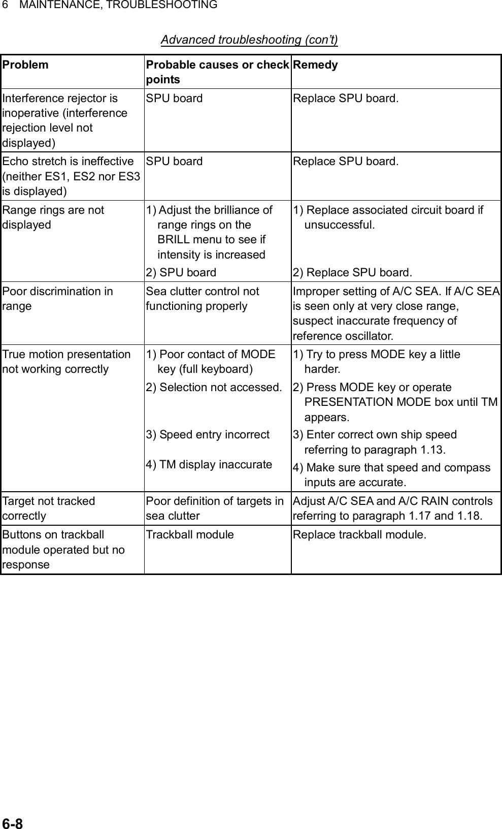
![6 MAINTENANCE, TROUBLESHOOTING 6-9 [CUSTOMIZE•TEST MENU] 1 BACK 2 [DATA BOX] 3 [F1] 4 [F2] 5 [F3] 6 [F4] 7 [OPERATION] 8 [TEST] [TEST] 1 BACK 2 [SELF TEST] 3 [ARPA TEST] 6.7 Diagnostics A diagnostic test program is provided to test major circuit boards in the control unit, processor unit and card I/F unit. Note that the normal radar picture is lost during this test. Proceed as follows to execute the diagnostic test: 1. Roll the trackball to choose the MENU box and then push the left button. 2. Roll the wheel to choose 9 [CUSTOMIZE•TEST] and then push the wheel or the left button. CUSTOMIZE•TEST menu 3. Roll the wheel to choose 8 [TEST] and then push the wheel or the left button. TEST menu 4. Roll the wheel to choose 2 [SELF TEST] and push the wheel or the left button. SELF TEST menu 5. Roll the wheel to choose 2 START and then push the wheel or the left button to start the test. In a few moments the results of the test are displayed and the buzzer sounds continuously. The ROMs and RAMs of the SPU, RFC, KEYBOARD (Control Unit), REMOTE (Trackball-only Control Unit) and CARD I/F UNIT are checked for proper operation. OK appears for normal operation. If NG (No Good) appears, corresponding components may be defective. Consult your dealer. In the middle of the display the rpm of the antenna unit and various voltages are displayed. [SELFT TEST] 1 BACK 2 START](https://usermanual.wiki/Furuno-USA/9ZWRTR078/User-Guide-356443-Page-223.png)
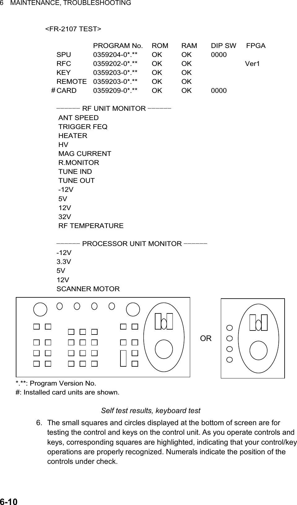
![6 MAINTENANCE, TROUBLESHOOTING 6-117. Press the [F1] key to change the display. The buzzer stops and the screen shows the sentences being input to the radar, under the categories of GPS1 and GPS2 (position), speed, heading and nav data. Below is an example. (The sentences shown depend on your system settings.) <GPS1>GGAGLLRMCRMBRMAVTGZDADTMBWRBWC<GPS2>GGAGLLRMCRMBRMAVTGZDADTMBWRBWC<SPEED>VBWVHWVDR<HDG>HDT<NAV DATA>WPLRTEMWVVWTDPTDBTDBSMTW Sentence input display 8. To terminate the test, press the [F1] key.](https://usermanual.wiki/Furuno-USA/9ZWRTR078/User-Guide-356443-Page-225.png)

![AP-1APPENDIX 1. Menu Tree Main menu (accessed by MENU key or MENU box) 1 ECHO2 MARK3 ALARM(Continued on next page)1 BACK2 2ND ECHO REJ (OFF, ON)3 TUNE INITIALIZE4 PM (OFF, ON)5 SART (OFF, ON)6 WIPER (OFF, 1, 2)1 BACK2 OWN SHIP MARK (OFF, ON)3 STERN MARK (OFF, ON)4 INDEX LINE BEARING (REL, TRUE)5 INDEX LINE (1, 2, 3, 6)6 INDEX LINE MODE (VERTICAL, HORIZONTAL)*7 8 EBL OFFSET BASE POINT (STAB GND, STAB HDG, STAB NORTH)9 EBL CURSOR BEARING (REL, TRUE)0 RING (OFF, ON)1 BACK2 GUARD ALARM MODE (IN, OUT)3 GUARD ALARM LEVEL (1, 2, 3, 4)4 WATCH ALARM (OFF, 6MIN, 10MIN, 12MIN, 15MIN, 20MIN)5 ALARM SOUND LEVEL (LOW, MID, HIGH)6 [ALARM OUT1]7 [ALARM OUT2]8 [ALARM OUT3]MENU keyorMENU box1 BACK2 (GUARD ALARM, WATCH ALARM,GUARD ZONE, LOST TARGET, CPALIMIT, AUTO ACQ TARGET FULL,MAN ACQ TARGET FULL, ARPASYSTEM ERROR, AZIMUTH, HEADLINE, TRIGGER, VIDEO, GYRO, LOG,EPFS, XTE, ARRIVAL WPT, DEPTH)* Appears when 5 INDEX LINE is set for other than "1".](https://usermanual.wiki/Furuno-USA/9ZWRTR078/User-Guide-356443-Page-227.png)
![APPENDIX AP-2 4 ARPA AIS5 PLOTTER1 BACK2 GUARD ZONE STAB (STAB HDG, STAB NORTH)3 GUARD POLYGON (OFF, STAB GND, STAB HDG, STAB NORTH)4 [TRIAL MANEUVER]5 [ARPA SYMBOL]6 [AIS SYMBOL]7 [FUSION] 1 BACK2 TRIAL (OFF, STATIC, DYNAMIC)3 TRIAL SPEED RATE (00.0 kt, 0.00 kt/s, two sets)4 TRIAL TURN RATE (00.0 kt, 0.00 kt/s, two sets)1 BACK2 ARPA SYMBOL COLOR (RED, GRN, BLU, YEL, CYA, MAG, WHT) 3 ARPA SYMBOL SIZE (SMALL, STD, LARGE)4 ARPA PAST POSN COLOR (RED, GRN, BLU, YEL, CYA, MAG, WHT) 5 ARPA PAST POSN POINTS (5, 10)1 BACK2 AIS SYMBOL COLOR (RED, GRN, BLU, YEL, CYA, MAG, WHT)3 AIS SYMBOL SIZE (SMALL, STD, LARGE)4 ROT TAG LIMIT (0 - 180.0 /min)5 AIS PAST POSN COLOR (RED, GRN, BLU, YEL, CYA, MAG, WHT)6 ARPA PAST POSN POINTS (5, 10)1 BACK2 FUSION TARGET (OFF/ON)3 GAP (0.000 - 9.999 (nm))4 RANGE (0.000 - 9.999 (nm))5 BEARING (0 - 359 )6 SPEED (0.0 - 9.9 (kt))7 COURSE (0 - 359 )8 AIS FUNCTION (OFF, ON)1 BACK2 CHART COLOR (GRN, YEL, CYA, ORANGE, GRAY)3 OWN TRACK INTERVAL (OFF, 10SEC, 30SEC, 1MIN, 2MIN, 3MIN, 6MIN)4 OWN TRACK COLOR (RED, GRN, BLU, YEL, CYA, MAG, WHT)5 TARGET TRACK INTERVAL (10SEC, 30SEC, 1MIN, 2MIN, 3MIN, 6MIN)6 TARGET TRACK COLOR (RED, GRN, BLU, YEL, CYA, MAG, WHT)7 CURSOR L/L ALIGN (OFF, ON)8 [DATA ERASE] 1 BACK2 OWN TRACK (30%/50%/80%/ALL)3 TARGET TRACK (30%/50%/80%/ALL)4 MARK ALL ERASE5 WP ALL ERASE6 NAV LINE ALL ERASE(Continued on next page)(Continued from previous page)](https://usermanual.wiki/Furuno-USA/9ZWRTR078/User-Guide-356443-Page-228.png)
![APPENDIX AP-3 9 [DISPLAY] 1 BACK2 GRID (OFF, ON)3 OWN TRACK (OFF, ON)4 TARGET TRACK (OFF, ON)5 MARK (OFF, ON)6 LAND DENSITY (OFF, ON)7 PLACE NAME (OFF, ON)8 COAST LINE (OFF, ON)9 CONTOUR LINE (OFF, ON)0 NEXT 1 BACK2 NAV LINE(MAP) (OFF, ON)3 DANGER HIGHLIGHT (OFF, ON)4 PROHIBITED AREA (OFF, ON)5 BUOY (OFF, ON)(Continued on next page)(Continued from previous page)6 CARD7 NAV DATA8 NAV LINE WPT1 BACK2 DRIVE SELECT (A, B, C, D, E, F, G, H)3 [READ CARD]4 [WR MARK]5 [WR WPT NAV LINE]6 [WR OWN TRACK]7 [WR TARGET TRACK]8 [WR SETTING DATA]9 [WR INSTALLATION DATA]0 NEXT 1 BACK2 FILE DELETE3 CARD INITIALIZE1 BACK2 DEPTH (OFF, m, ft)3 DEPTH GRAPH SCALE (10, 20, 50, 100, 200, 500)4 DEPTH MARK (000 - 500)5 CURRENT (OFF, ON)6 WIND (OFF, m/s, kt)7 TEMP (OFF, ON)8 DATE-TIME (OFF, UTC, LOCAL)9 LOCAL TIME ADJ (00:00 - +13:30)0 WPT DATA (OFF, REL, TRUE)1 BACK2 NAV LINE DATA SOURCE (OFF, EXT DATA, INTERNAL DATA, WPT MARK)3 NAV LINE SELECT (Enter nav line no.)4 ARRIVAL WPT ALARM (OFF, ON)5 NAV LINE WIDTH (0.0 - 9.9 (nm))6 [WPT SET] 1 BACK2 WPT NO. SELECT3 WPT NAME4 WPT L/L5 CLEAR DATA](https://usermanual.wiki/Furuno-USA/9ZWRTR078/User-Guide-356443-Page-229.png)
![APPENDIX AP-4 7 [WPT LIST]8 [NAV LINE SET]9 [NAV LINE LIST]0 NEXT(Continued on next page)(Continued from previous page)9 CUSTOMIZE TEST1 BACK2 [DATA BOX]3 [F1]4 [F2]5 [F3]6 [F4] 1 BACK2 NAV LINE NO. SELECT3 NAV LINE NAME4 [NAV LINE ENTRY]5 CLEAR DATA1 BACK2 NAV LINE WPTS1 BACK2 SKIP NEXT WPT3 TURNING LINE (OFF, ON, REVISED)4 DISP WPT NO. (OFF, ON)5 DISP WPT NAME (OFF, ON)1 BACK23 NAV DATA (OFF, ON)4 ZOOM (OFF, 2TIMES, 3TIMES)5 ZOOM DISPLAY (REL, STAB, ACQ)6 TARGET DATA (1BOX, 2BOX, 3BOX, LARGE)1 BACK2 [ECHO]3 [STD KEY]4 [ARPA AIS]5 [OPERATION]1 BACK2 (PICTURE, IR, ES, EAV, NOISEREJ, ANT SELECT, PULSE LENGTH,A/C SEA SELECT, A/C RAINSELECT, TUNE SELECT, ANTHEIGHT, SEA CONDITION, 2NDECHO REJ, PM, SART)1 BACK2 (ALARM ACK, STBY TX, HLOFF, EBL OFFSET, MODE, OFFCENTER, CU TM RESET, INDEXLINE, VECTOR TIME, VECTORMODE, TARGET LIST, TRAIL,BRILL, MARK, MENU, RANGEUP, RANGE DOWN, ACQ, TARGET DATA, TARGET CANCEL)1 BACK2 (DISP ARPA, DISP AIS, TARGETDATA & ACQ, PAST POSNINTERVAL, REF MARK, CPALIMIT, CPA, TCPA, GZ1, GZ2,TARGET LIST SORT, TRIALMANEUVER, ARPA AIS FUSION,AIS MESSAGE)1 BACK2 (ECHO COLOR, BACK COLOR,RING, ALARM1, ALARM2, WATCHALARM RESET, ZOOM, MARKDELETE, CHART ALIGN,DISPLAY SELECT, MOB, USER DEFAULT, TLL)](https://usermanual.wiki/Furuno-USA/9ZWRTR078/User-Guide-356443-Page-230.png)
![APPENDIX AP-57 [OPERATION]8 [TEST](Continued from previous page)1 BACK2 WHEEL DRIVE (NORMAL, REVERSE)3 KEY BEEP** (OFF, LO, MID, HI)4 EAV W/O GYRO (OFF, ON)5 REMOTE KEY (F*-KEY, DISPLAY SELECT)6 7 OWN SHIP VECTOR (OFF, HDG, COURSE) 1 BACK2 [SELF TEST]3 [ARPA TEST]** Not available on IMO radar.1 BACK2 START](https://usermanual.wiki/Furuno-USA/9ZWRTR078/User-Guide-356443-Page-231.png)
![APPENDIX AP-6 Pop-up menus of on-screen boxes [ARPA TARGET MENU] 1 ARPA SELECT MANUAL100/AUTO 25/AUTO 50/AUTO 75/AUTO 100 ALL CANCEL 23 REF TARGET VECTOR OFF/ON ARPA TARGET menu[AIS TARGET MENU] 1 SLEEP ALL TGTS2 ACTIVATE ALL TGTS 3 AUTO DISPLAY MESSAGE OFF/ON 4 [RECEIVED MSGS] 5 6 7 8 [AIS ALARM MSGS] AIS TARGET menu[HDG MENU] 1 HDG SOURCE AD -10/SERIAL 2 GC -10 SETTING 000.0 HDG menu [SPEED MENU] 1 SHIP SPEED LOG(BT)/LOG(WT)/ GPS/MANUAL/REF 2 MANUAL SPEED 0.0kt 3 SET DRIFT OFF/ON SPEED menuOS POSN menu[OS POSN MENU] 1 NAV AID GPS1/GPS2/ DEAD RECKONING 2 MANUAL L/L 00 00.00 N 000 00.00 W [TRAIL MENU] 1 TRAIL MODE REL/TRUE/PAST ECHO 2 TRAIL GRAD SINGLE/MULTI 3 4 TRAIL LEVEL 1/2/3/4 5 TRAIL RESTART OFF/ON 6 TRAIL COPY OFF/ON 7 OS TRAILOFF/ON [TGT LIST MENU] CPA/TCPA/BCR/BCT/RANGE/SPEEDTGT LIST menu1 SORT BY [CURSOR MENU] 2 TARGET DATA & ACQ/ TARGET CANCEL/ ACQ/ REF MARK/ EBL OFFSET/ ZOOM/ MARK DELETE/ CHART ALIGN CURSOR menuOS TRAILOFF/ONTRAIL menu](https://usermanual.wiki/Furuno-USA/9ZWRTR078/User-Guide-356443-Page-232.png)
![APPENDIX AP-7 [BRILL1 MENU (2/2)]1 BACK2 BEARING CURSOR3 EBL4 VRM5 INDEX LINE6 ARPA SYMBOL7 AIS SYMBOL8 L/L GRID9 MARK0 CHART [BRILL1 MENU (1/2)]1 ECHO COLOR YEL/GRN/ WHT/COLOR*2 BKGD COLOR BLK-GRN/ BLK-RED/ BLU-CIR/ BLU/BRT-BLU3 PANEL DIMMER4 CHARACTER5 CURSOR6 ECHO7 TRAIL8 HL9 RING0 NEXTBRILL menu, page 1BRILL menu, page 2[PICTURE MENU] 1 INT REJECT OFF/1/2/3 2 ECHO STRETCH OFF/1/2/3 3 ECHO AVERAGE OFF/1/2/3 4 NOISE REJ OFF/ON 5 AUTO STC OFF/ON 6 AUTO RAIN 7 VIDEO CONTRAST A/B/C/D 8 [PULSE] 9 [CONDITION] [PULSE MENU] 1 BACK 2 0.5NM S1/S2 3 0.75NM S1/S2/M1 4 1.5NM S1/S2/S3 5 3NM S2/M1/M2/M3 6 6NM M1/M2/M3/L 7 12-24NM M2/M3/L PICTURE menuOFF/ONPULSE menuCONDITION menu[CONDITION MENU] 1 BACK 2 SEA CONDITION 1/2/3/4/5 3 ANT HEIGHT 5/7.5/10/15/20/25/30/ 35/40/45/ more 50 m 4 STC RANGE 000m * Not available on IMO radar. ANTENNA INFORMATION display[ANT INFORMATION]ANT NO 1 BAND : X-BAND MODEL: 12 POS : FOREANT NO 2 BAND : X-BAND MODEL: 12 POS : FORE0 DEFAULTNote: For default settings for each picturesetup type see paragraph 1.33.MARK menu [MARK MENU] 1 ORIGIN MARK STAB GND/SEA 2 ORIGIN MARK(No.)/ ORIGIN MARK(SYMBOL)/ MAP MARK/ WP 1~50/ WP 51~100/ WP 101~150/ WP 151~200/ OWN SHIP SHAPE 9 MAP DISPLAY OFF/ON 0 MAP MARK COLOR* RED/GRN/BLU/YEL/ CYA/MAG/WHT](https://usermanual.wiki/Furuno-USA/9ZWRTR078/User-Guide-356443-Page-233.png)