Furuno USA 9ZWRTR078A Marine Radar User Manual FAR2xx7 OME
Furuno USA Inc Marine Radar FAR2xx7 OME
Contents
- 1. ops manual
- 2. inst manual part 1
- 3. inst manual part2
ops manual

MARINE RADAR/ARPA
FAR-28x7 Series
FAR-21x7(-BB) Series
OPERATOR'S MANUAL
www.furuno.co.jp
MODEL
Complies with
IMO MSC.192(79)

i
IMPORTANT NOTICES
General
• The operator of this equipment must read and follow the descriptions in this manual.
Wrong operation or maintenance can cancel the warranty or cause injury.
• Do not copy any part of this manual without written permission from FURUNO.
• If this manual is lost or worn, contact your dealer about replacement.
• The contents of this manual and equipment specifications can change without notice.
• The example screens (or illustrations) shown in this manual can be different from the
screens you see on your display. The screens you see depend on your system
configuration and equipment settings.
• Save this manual for future reference.
• Any modification of the equipment (including software) by persons not authorized by
FURUNO will cancel the warranty.
• All brand and product names are trademarks, registered trademarks or service marks of
their respective holders.
How to discard this product
Discard this product according to local regulations for the disposal of industrial waste. For
disposal in the USA, see the homepage of the Electronics Industries Alliance
(http://www.eiae.org/) for the correct method of disposal.
How to discard a used battery
Some FURUNO products have a battery(ies). To see if your product has a battery, see the
chapter on Maintenance. Follow the instructions below if a battery is used. Tape the + and -
terminals of battery before disposal to prevent fire, heat generation caused by short circuit.
In the European Union
The crossed-out trash can symbol indicates that all types of
batteries must not be discarded in standard trash, or at a trash
site. Take the used batteries to a battery collection site
according to your national legislation and the Batteries Directive
2006/66/EU.
In the USA
The Mobius loop symbol (three chasing arrows) indicates that
Ni-Cd and lead-acid rechargeable batteries must be recycled.
Take the used batteries to a battery collection site according to
local laws.
In the other countries
There are no international standards for the battery recycle symbol. The number of symbols
can increase when the other countries make their own recycling symbols in the future.
Cd
Ni-Cd Pb
SAFETY INSTRUCTIONS
ii
Mandatory Action
Prohibitive Action
WARNING
Indicates a potentially hazardous situation which, if not avoided,
could result in death or serious injury.
CAUTION
Indicates a potentially hazardous situation which, if not avoided,
can result in minor or moderate injury.
Warning, Caution
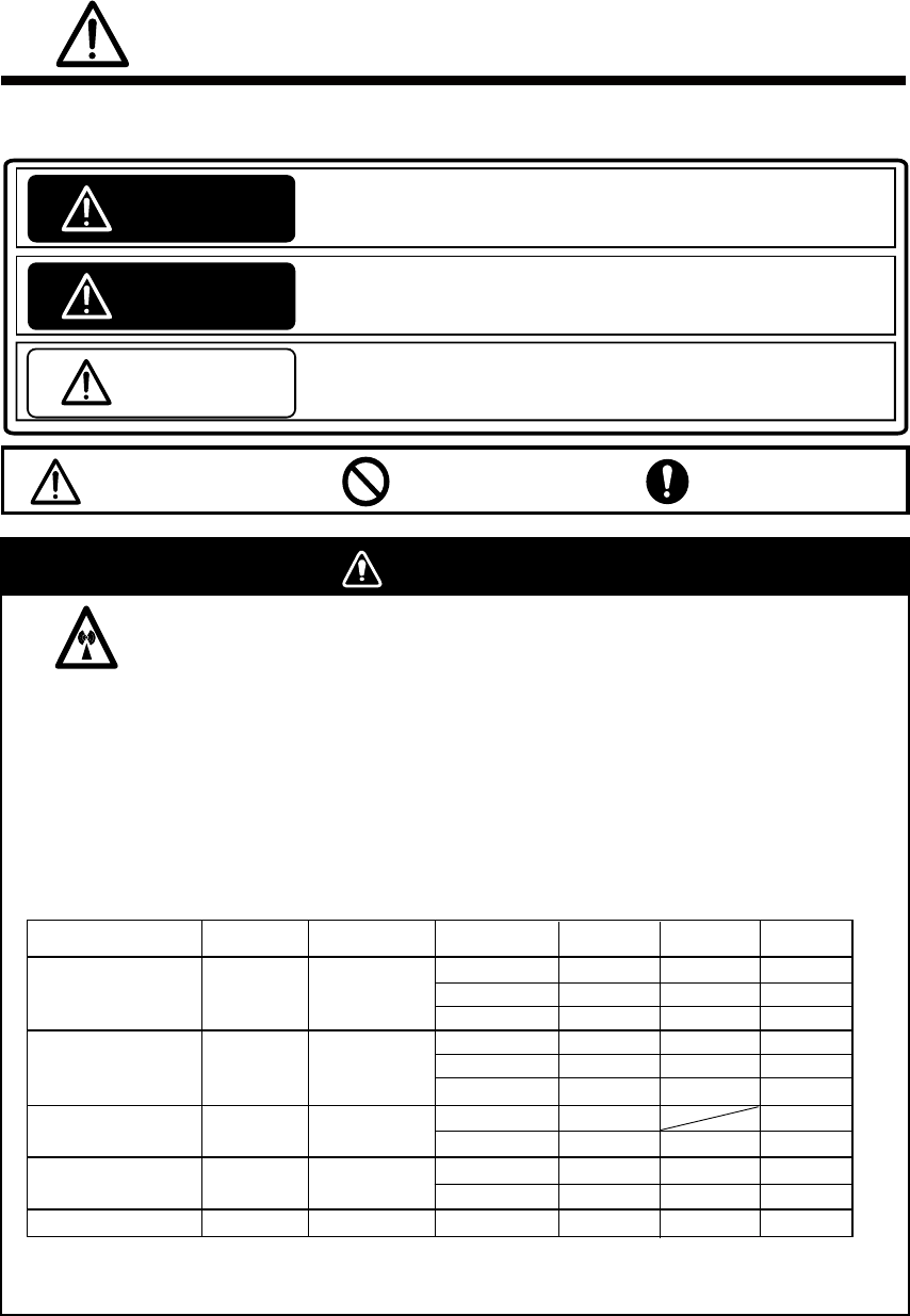
SAFETY INSTRUCTIONS
The operator and installer must read the applicable safety instructions before attempting to
install or operate the equipment.
WARNING
Radio Frequency Radiation Hazard
The radar antenna emits electromagnetic radio frequency (RF) energy which can be harmful,
particularly to your eyes. Never look directly into the antenna aperture from a close distance
while the radar ius in operation or eexpose yourself to the transmitting antenna at a close
distance. Distances at which RF radiation level of 100, 50 and 10 W/m are given in the table
below.
Note: If the antenna unit is installed at a close distance in front of the wheel house, your
administration may require halt of transmission within a certain sector of antenna revolution.
This is possible. Ask your FURUNO representive or dealer to provide this feature.
2
DANGER
Indicates a potentially hazardous situation which, if not avoided,
will result in death or serious injury.
*1 XN12AF: 120cm, XN20AF: 198cm, XN24AF: 243cm, SN30AF: 309cm, SN36AF: 377cm
100W/m
2
Radar model
FAR-2127/2827
FAR-2117/2817
XN12AF
XN20AF
XN24AF
XN12AF
XN20AF
XN24AF
SN30AF
0.3m
0.1m
0.1m
0.9m
0.5m
0.2m
FAR-2137S/2837S
XN20AF
FAR-2837SW
FAR-2827W
Transceiver Magnetron
RTR-079A MG5436
RTR-078A
RTR-080
RTR-081A
RTR-082
MAF-1565N
MG5223F
MG5436
MG5223F SN36AF
Antenna *1
0.1m
0.4m
10W/m
2
3.7m
2.2m
1.5m
9.0m
4.6m
3.3m
2.4m
5.6m
1.9m
50W/m
2
1.2m
0.7m
0.4m
2.6m
1.7m
1.0m
1.0m
0.2m
SN36AF 0.1m 2.0m
0.7m
XN24AF 0.2m 3.4m
0.5m
-
SAFETY INSTRUCTIONS
iii
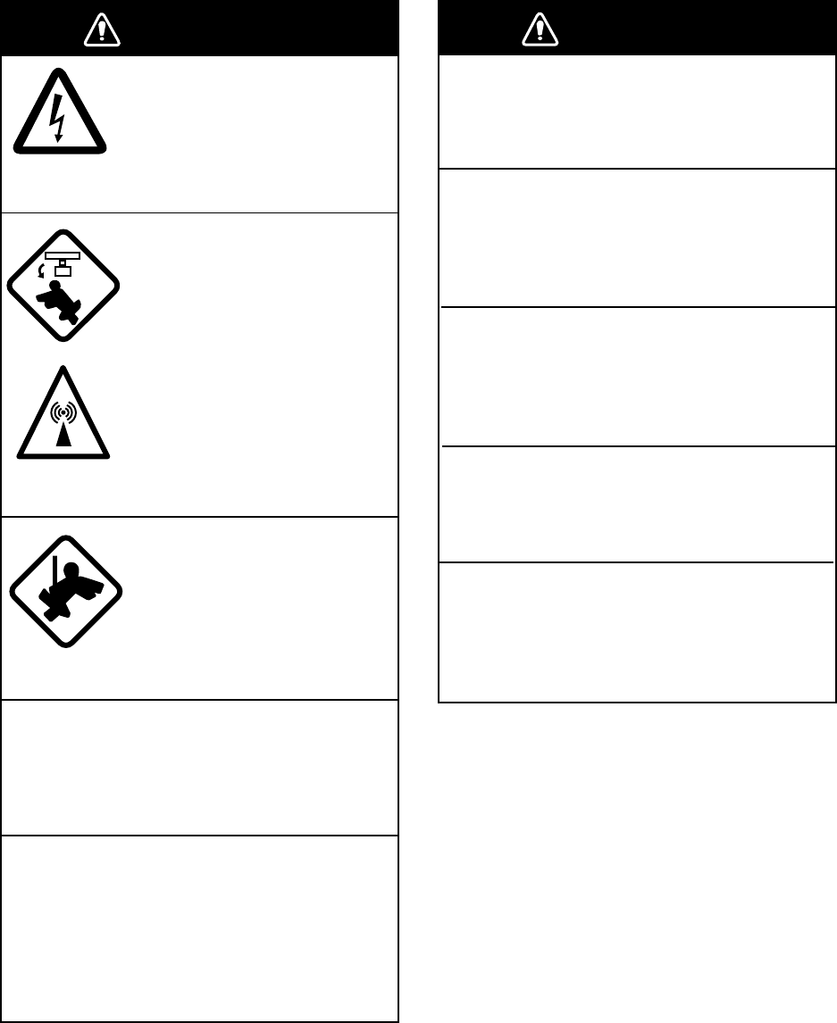
WARNING
ELECTRICAL SHOCK HAZARD
Do not open the equipment.
Only qualified personnel
should work inside the
equipment.
Turn off the radar power
switch before servicing the
antenna unit. Post a warn-
ing sign near the switch
indicating it should not be
turned on while the antenna
unit is being serviced.
Prevent the potential risk of
being struck by the rotating
antenna and exposure to
RF radiation hazard.
Wear a safety belt and hard
hat when working on the
antenna unit.
Serious injury or death can
result if someone falls from
the radar antenna mast.
Do not disassemble or modify the
equipment.
Fire, electrical shock or serious injury can
result.
Immediately turn off the power at the
ship's mains switchboard if water
leaks into the equipment or the equip-
ment is emitting smoke or fire.
Continued use can cause fatal damage to
the equipment.
WARNING
Use the proper fuse.
Use of a wrong fuse can result in damage
to the equipment or cause fire.
Keep heater away from equipment.
Heat can alter equipment shape and melt
the power cord, which can cause fire or
electrical shock.
Do not place liquid-filled containers
near the equipment.
Fire or electrical shock can result if a liquid
spills into the equipment.
Do not operate the equipment with wet
hands.
Electrical shock can result.
Before servicing the radar, turn off
the appropriate external breaker.
Power is not removed from the radar simply
by turning off its power switch.
SAFETY INSTRUCTIONS
iv
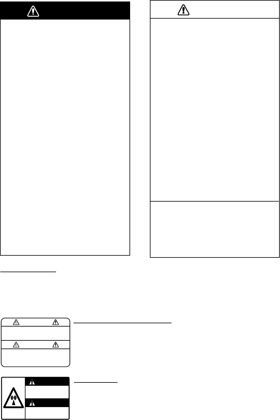
WARNING
No one navigational aid should be relied
upon for the safety of vessel and crew.
The navigator has the responsibility to
check all aids available to confirm
position. Electronic aids are not
a substitute for basic navigational
principles and common sense.
• This TT automatically tracks
automatically or manually acquired radar
targets and calculates their courses and
speeds, indicating them by vectors. Since
the data generated by the auto plotter
are based on what radar targets are
selected, the radar must always be
optimally tuned for use with the auto
plotter, to ensure required targets will not
be lost or unwanted targets such as sea
returns and noise will not be acquired
and tracked.
• A target does not always mean a land-
mass, reef, ships or other surface vessels
but can imply returns from sea surface
and clutter. As the level of clutter changes
with environment, the operator should
properly adjust the A/C SEA, A/C RAIN
and GAIN controls to be sure target
echoes are not eliminated from the
radar screen.
CAUTION
The plotting accuracy and response of
this TT meets IMO standards.
Tracking accuracy is affected by the
following:
• Tracking accuracy is affected by course
change. One to two minutes is required to
restore vectors to full accuracy after an
abrupt course change. (The actual
amount depends on gyrocompass
specifications.)
• The amount of tracking delay is inversely
proportional to the relative speed of the
target. Delay is on the order of 15—30
seconds for high relative speed; 30—60
seconds for low relative speed.
• Display accuracy is affected by the
following:
- Echo intensity
- Radar transmission pulsewidth
- Radar bearing error
- Gyrocompass error
- Course change (own ship and target)
The data generated by TT, AIS and
video plotter are intended for
reference only.
Refer to official nautical charts for
detailed and up-to-date information.
WARNING
To avoid electrical shock, do not
remove cover. No user-serviceable
parts inside.
WARNING LABEL
Warning labels are attached to the
equipment. Do not remove any label.
If a label is missing or damaged,
contact a FURUNO agent or dealer
about replacement.
WARNING
Radiation hazard. Only qualified
personnel should work inside scanner.
Confirm that TX has stopped before
opening scanner.
DISPLAY UNIT, PROCESSOR UNIT
Name: Warning Label (1)
Type: 86-003-1011-1
Code No.: 100-236-231
ANTENNA UNIT
Name: Radiation Warning Label
Type:
03-142-3201-0
Code No.: 100-266-890

v
TABLE OF CONTENTS
FOREWORD ........................................................................................................ xi
PROGRAM NUMBER ......................................................................................... xv
SYSTEM CONFIGURATION.............................................................................. xvi
1. RADAR OPERATION....................................................................................1-1
1.1 Turning on the Power .................................................................................................. 1-1
1.2 Transmitter ON ............................................................................................................ 1-1
1.3 Control Unit ................................................................................................................. 1-3
1.4 Main Menu................................................................................................................... 1-5
1.5 Operation by the On-Screen Boxes ............................................................................ 1-7
1.6 Cursor Menu.............................................................................................................. 1-10
1.7 Monitor Brilliance........................................................................................................1-11
1.8 Display Modes........................................................................................................... 1-12
1.9 On-Screen Boxes and Markers ................................................................................. 1-13
1.10 Tuning the Receiver .................................................................................................. 1-15
1.10.1 Choosing the tuning method........................................................................... 1-15
1.10.2 Initializing tuning ............................................................................................. 1-15
1.10.3 Automatic tuning ............................................................................................. 1-16
1.10.4 Manual tuning ................................................................................................. 1-16
1.11 Aligning Heading with Gyrocompass......................................................................... 1-16
1.12 Presentation Modes................................................................................................... 1-17
1.12.1 Choosing presentation mode.......................................................................... 1-17
1.12.2 Description of presentation modes ................................................................. 1-18
1.13 Entering Own Ship's Speed....................................................................................... 1-22
1.13.1 Automatic speed input by log or GPS navigator ............................................. 1-22
1.13.2 Manual speed input ........................................................................................ 1-23
1.14 Choosing a Range Scale........................................................................................... 1-23
1.15 Choosing a Pulselength ............................................................................................ 1-24
1.15.1 Choosing a pulselength .................................................................................. 1-24
1.15.2 Changing pulselength ..................................................................................... 1-25
1.16 Adjusting the Sensitivity ............................................................................................ 1-26
1.17 Reducing Sea Clutter ................................................................................................ 1-27
1.17.1 Choosing method of adjustment ..................................................................... 1-27
1.17.2 Automatic reduction of sea clutter .................................................................. 1-27
1.17.3 Manual reduction of sea clutter....................................................................... 1-28
1.18 Reducing Rain Clutter ............................................................................................... 1-29
1.18.1 Automatic reduction of rain clutter .................................................................. 1-29
1.18.2 Manual reduction of rain clutter ...................................................................... 1-29
1.19 Measuring Range ...................................................................................................... 1-31
1.19.1 Showing, hiding the fixed range rings............................................................. 1-31
1.19.2 Measuring range by the variable range marker (VRM)................................... 1-32
1.19.3 VRM unit of measurement (B and C types) .................................................... 1-33
1.19.4 TTG to VRM indication ................................................................................... 1-33
1.20 Measuring Bearing .................................................................................................... 1-34
1.20.1 Measuring bearing .......................................................................................... 1-34
1.20.2 True or relative bearing................................................................................... 1-35
1.21 Collision Assessment by Offset EBL ......................................................................... 1-36
1.21.1 How to assess risk of collision by the offset EBL............................................ 1-36
1.21.2 Point of reference for origin point of offset EBL .............................................. 1-37
TABLE OF CONTENTS
vi
1.22 Measuring Range and Bearing Between Two Targets ...............................................1-38
1.23 Target Alarm...............................................................................................................1-39
1.23.1 How to set a target alarm ................................................................................1-39
1.23.2 Acknowledging the target alarm ......................................................................1-40
1.23.3 Deactivating a target alarm..............................................................................1-40
1.23.4 Target alarm attributes.....................................................................................1-41
1.24 Off-Centering the Display...........................................................................................1-42
1.25 Interference Rejector..................................................................................................1-43
1.26 Echo Stretch...............................................................................................................1-43
1.27 Echo Averaging..........................................................................................................1-44
1.28 Noise Rejector............................................................................................................1-45
1.29 Wiper..........................................................................................................................1-46
1.30 Target Trails................................................................................................................1-47
1.30.1 True or relative trails........................................................................................1-47
1.30.2 Trail time..........................................................................................................1-48
1.30.3 Trail gradation..................................................................................................1-48
1.30.4 Saving, copying target trails ............................................................................1-49
1.30.5 Trail level .........................................................................................................1-50
1.30.6 Narrow trails (B, C and W types) .....................................................................1-50
1.30.7 Longer trails (B, C and W types) .....................................................................1-51
1.30.8 Temporarily removing trails from the display ...................................................1-51
1.30.9 Trail stabilization in true motion .......................................................................1-51
1.30.10 Erasing trails..................................................................................................1-51
1.31 PI (Parallel Index) Lines.............................................................................................1-52
1.31.1 Displaying, erasing PI lines .............................................................................1-52
1.31.2 Adjusting PI line orientation, PI line interval ....................................................1-53
1.31.3 PI line bearing reference .................................................................................1-53
1.31.4 Maximum number of PI lines to display...........................................................1-54
1.31.5 PI line orientation.............................................................................................1-54
1.31.6 Resetting PI lines ............................................................................................1-54
1.32 Origin Mark.................................................................................................................1-55
1.32.1 Entering origin marks ......................................................................................1-55
1.32.2 Origin mark stabilization ..................................................................................1-57
1.32.3 Deleting individual origin marks.......................................................................1-57
1.33 Zoom..........................................................................................................................1-58
1.34 Markers ......................................................................................................................1-59
1.34.1 Heading line ....................................................................................................1-59
1.34.2 Stern marker....................................................................................................1-59
1.34.3 North marker ...................................................................................................1-59
1.34.4 Own ship symbol .............................................................................................1-60
1.34.5 Barge marker...................................................................................................1-61
1.34.6 INS marker ......................................................................................................1-61
1.35 Automatic Picture Setup According to Navigation Purpose .......................................1-62
1.35.1 Selecting a picture setup option ......................................................................1-64
1.35.2 Programming and saving picture setups .........................................................1-64
1.35.3 Restoring user settings....................................................................................1-66
1.35.4 Restoring default picture setup options ...........................................................1-66
1.35.5 Disabling unnecessary picture setups.............................................................1-67
1.36 Function Keys ............................................................................................................1-68
1.36.1 Activating function keys...................................................................................1-68
1.36.2 Programming function keys.............................................................................1-68
1.37 Ship’s Position............................................................................................................1-72
1.38 Second-trace Echoes.................................................................................................1-74
TABLE OF CONTENTS
vii
1.39 Brilliance of Screen Data........................................................................................... 1-75
1.40 Watch Alarm .............................................................................................................. 1-76
1.41 Nav Data ................................................................................................................... 1-77
1.42 Text Window .............................................................................................................. 1-79
1.43 Customizing Operation.............................................................................................. 1-81
1.44 Alert Box.................................................................................................................... 1-83
1.44.1 Alarm description ............................................................................................ 1-84
1.44.2 Alarm list ......................................................................................................... 1-87
1.44.3 Outputting alarm signals ................................................................................. 1-88
1.44.4 Primary alarm ................................................................................................. 1-89
1.45 Interswitch ................................................................................................................. 1-90
1.45.1 Displaying antenna information ...................................................................... 1-90
1.45.2 Presetting antenna and display combinations ................................................ 1-91
1.45.3 Selecting an antenna ...................................................................................... 1-93
1.46 Cursor Data ............................................................................................................... 1-93
1.47 Performance Monitor................................................................................................. 1-94
1.47.1 Activating, deactivating the performance monitor........................................... 1-94
1.47.2 Checking radar performance .......................................................................... 1-94
1.48 Own Ship Marker....................................................................................................... 1-96
1.49 Color and Brilliance Sets ........................................................................................... 1-97
1.49.1 Selecting color and brilliance set .................................................................... 1-97
1.49.2 Presetting color and brilliance set................................................................... 1-97
1.50 Reference Position .................................................................................................... 1-99
1.51 Switching Hub HUB-100 (option) ............................................................................ 1-101
1.52 Anchor Watch.......................................................................................................... 1-102
1.53 Drop Mark................................................................................................................ 1-103
1.53.1 Activating the drop mark feature................................................................... 1-103
1.53.2 Inscribing a drop mark .................................................................................. 1-104
1.53.3 Erasing a drop mark ..................................................................................... 1-104
1.54 Sub Monitor (B, C and W types) .............................................................................. 1-105
1.55 Net Cursor ............................................................................................................... 1-106
2. RADAR OBSERVATION ............................................................................... 2-1
2.1 General........................................................................................................................ 2-1
2.1.1 Minimum and maximum ranges........................................................................ 2-1
2.2 False Echoes............................................................................................................... 2-3
2.3 SART (Search and Rescue Transponder)................................................................... 2-5
2.3.1 SART description .............................................................................................. 2-5
2.3.2 Showing SART marks on the radar display ...................................................... 2-6
2.3.3 General remarks on receiving SARTs............................................................... 2-7
2.4 RACON ....................................................................................................................... 2-8
2.5 Radar Target Enhancer (RTE)..................................................................................... 2-8
3. TARGET TRACKING (TT)............................................................................. 3-1
3.1 Usage Precautions ...................................................................................................... 3-1
3.2 Controls for TT............................................................................................................. 3-2
3.3 Activating, Deactivating TT.......................................................................................... 3-3
3.4 Entering Own Ship's Speed......................................................................................... 3-3
3.4.1 Echo-referenced speed input............................................................................ 3-3
3.5 Automatic Acquisition .................................................................................................. 3-5
3.5.1 Enabling auto acquisition.................................................................................. 3-5
3.5.2 Terminating tracking of targets (including reference targets) ............................ 3-6
TABLE OF CONTENTS
viii
3.6 Manual Acquisition .......................................................................................................3-7
3.6.1 Setting manual acquisition conditions ...............................................................3-7
3.6.2 Manually acquiring targets.................................................................................3-7
3.7 Lost Target ...................................................................................................................3-9
3.7.1 Setting the lost target filter.................................................................................3-9
3.7.2 Enabling, disabling the lost target alarm............................................................3-9
3.8 TT Symbols and Attributes .........................................................................................3-10
3.8.1 TT symbols......................................................................................................3-10
3.8.2 Choosing TT symbol (B, C and W types) ........................................................ 3-11
3.8.3 TT symbol brilliance.........................................................................................3-11
3.8.4 TT symbol color...............................................................................................3-12
3.9 Displaying Target Data ...............................................................................................3-13
3.9.1 Displaying target data......................................................................................3-13
3.9.2 Target list .........................................................................................................3-15
3.10 Vector Modes .............................................................................................................3-16
3.10.1 Description of vectors......................................................................................3-16
3.10.2 Vector mode and length ..................................................................................3-17
3.11 Past Position Display .................................................................................................3-18
3.11.1 Displaying and erasing past position points, choosing past
position plot interval.........................................................................................3-18
3.11.2 Past position display attributes........................................................................3-19
3.11.3 Past position display mode..............................................................................3-19
3.11.4 Stabilization in true mode ................................................................................3-20
3.12 Set and Drift ...............................................................................................................3-20
3.13 TT Collision Alarm (CPA, TCPA) ................................................................................3-21
3.13.1 Setting the CPA and TCPA ranges ..................................................................3-21
3.13.2 Acknowledging the TT collision alarm .............................................................3-22
3.14 Acquisition Zone.........................................................................................................3-22
3.14.1 Activating an acquisition zone .........................................................................3-22
3.14.2 Sleeping, deactivating an acquisition zone......................................................3-23
3.14.3 Acknowledging the alarm ................................................................................3-23
3.14.4 Acquisition zone reference ..............................................................................3-24
3.14.5 Acquisition zone shape and stabilization.........................................................3-24
3.15 TT System Messages ................................................................................................3-25
3.16 Trial Maneuver ...........................................................................................................3-26
3.16.1 Types of trial maneuvers .................................................................................3-26
3.16.2 Performing a trial maneuver ............................................................................3-27
3.16.3 Terminating a trial maneuver ...........................................................................3-29
3.17 TT Performance Test..................................................................................................3-30
3.18 Criteria for Selecting Targets for Tracking ..................................................................3-32
3.19 Factors Affecting TT Functions...................................................................................3-34
4. AIS OPERATION........................................................................................... 4-1
4.1 Controls for AIS ............................................................................................................4-1
4.2 Showing, Hiding the AIS Display..................................................................................4-2
4.3 AIS Display Filter..........................................................................................................4-4
4.4 Activating Targets.........................................................................................................4-5
4.4.1 Activating specific targets manually...................................................................4-5
4.4.2 Activating all targets ..........................................................................................4-5
4.5 How to Sleep Targets ...................................................................................................4-6
4.5.1 Sleeping an individual target .............................................................................4-6
4.5.2 Sleeping all targets ............................................................................................4-6
4.6 Setting Up for a Voyage ...............................................................................................4-7
TABLE OF CONTENTS
ix
4.7 Target Data.................................................................................................................. 4-9
4.7.1 Basic target data............................................................................................... 4-9
4.7.2 Detailed target data......................................................................................... 4-10
4.7.3 Removing a target data display ...................................................................... 4-10
4.7.4 Canceling tracking on a target from target data display.................................. 4-10
4.8 AIS Symbol Attributes.................................................................................................4-11
4.8.1 AIS symbol brilliance .......................................................................................4-11
4.8.2 AIS symbol size and color ...............................................................................4-11
4.9 Past Position Display................................................................................................. 4-12
4.9.1 Past position plot interval................................................................................ 4-12
4.9.2 Past position points......................................................................................... 4-13
4.9.3 Past position display motion ........................................................................... 4-13
4.9.4 Stabilization in true motion.............................................................................. 4-13
4.10 Lost Target................................................................................................................. 4-14
4.10.1 Lost target filter ............................................................................................... 4-14
4.10.2 Enabling, disabling the lost target alarm......................................................... 4-15
4.11 ROT Setting............................................................................................................... 4-16
4.12 AIS Collision Alarm (CPA, TCPA) .............................................................................. 4-17
4.12.1 Setting the CPA and TCPA ranges.................................................................. 4-17
4.12.2 Enabling, disabling the AIS collision alarm ..................................................... 4-17
4.12.3 Limiting the function of the collision alarm ...................................................... 4-18
4.13 Association of TT and AIS Targets............................................................................. 4-19
4.14 Own Ship’s Data........................................................................................................ 4-21
4.15 Messages .................................................................................................................. 4-22
4.15.1 Creating, saving messages ............................................................................ 4-22
4.15.2 Transmitting messages................................................................................... 4-23
4.15.3 Viewing messages.......................................................................................... 4-24
4.16 AIS System Messages .............................................................................................. 4-26
5. VIDEO PLOTTER OPERATION....................................................................5-1
5.1 General........................................................................................................................ 5-1
5.2 Display Modes............................................................................................................. 5-1
5.3 Presentation Modes..................................................................................................... 5-2
5.4 Radar Map................................................................................................................... 5-3
5.4.1 Showing, hiding the radar map display............................................................. 5-3
5.4.2 Inscribing radar map marks and lines............................................................... 5-4
5.5 Erasing Radar Map Marks and Lines .......................................................................... 5-6
5.5.1 Erasing individual radar map marks and lines .................................................. 5-6
5.5.2 Erasing all radar map marks and lines ............................................................. 5-7
5.6 Radar Map Corrections ............................................................................................... 5-8
5.6.1 Radar map correction ....................................................................................... 5-8
5.6.2 Cursor data correction ...................................................................................... 5-8
5.7 Chart Cards (A, B, C and W types) ............................................................................. 5-9
5.7.1 Displaying a chart ............................................................................................. 5-9
5.7.2 Chart position correction................................................................................. 5-10
5.7.3 Correcting cursor data .................................................................................... 5-10
5.7.4 Chart land color (B, C and W types) ................................................................5-11
5.8 Hiding, Showing Graphics on the Video Plotter Display............................................ 5-12
5.9 Track.......................................................................................................................... 5-13
5.9.1 Plotting own ship’s track ................................................................................. 5-13
5.9.2 Plotting interval for other ships' tracks ............................................................ 5-14
5.9.3 Auto target track (A, B, C and W types).......................................................... 5-15
5.9.4 Choosing track color (A, B, C and W types) ................................................... 5-15
TABLE OF CONTENTS
x
5.9.5 Erasing track from the menu, on the screen....................................................5-16
5.9.6 Erasing track with the cursor ...........................................................................5-17
5.10 Waypoints ..................................................................................................................5-18
5.10.1 Entering waypoints ..........................................................................................5-18
5.10.2 Editing, erasing waypoints from the menu.......................................................5-20
5.10.3 Erasing waypoints ...........................................................................................5-21
5.10.4 Waypoint list ....................................................................................................5-22
5.10.5 Displaying waypoint name and number...........................................................5-23
5.11 Nav Lines ...................................................................................................................5-24
5.11.1 Entering a new nav line ...................................................................................5-24
5.11.2 Editing a nav line .............................................................................................5-25
5.11.3 Nav line list ......................................................................................................5-26
5.11.4 Erasing a nav line............................................................................................5-27
5.11.5 Setting up nav lines .........................................................................................5-28
5.11.6 Displaying nav line, waypoint mark .................................................................5-30
5.12 Recording Data ..........................................................................................................5-32
5.12.1 Initializing memory (RAM) cards......................................................................5-32
5.12.2 Recording data ................................................................................................5-33
5.13 Replaying Data...........................................................................................................5-35
5.14 Deleting Files .............................................................................................................5-36
6. MAINTENANCE, TROUBLESHOOTING...................................................... 6-1
6.1 Periodic Maintenance Schedule...................................................................................6-2
6.2 Life Expectancy of Major Parts ....................................................................................6-3
6.3 Replacing the Fuse ......................................................................................................6-4
6.4 Replacement of Battery on GC Board..........................................................................6-4
6.5 Trackball Maintenance .................................................................................................6-5
6.6 Easy Troubleshooting...................................................................................................6-6
6.7 Advanced-level Troubleshooting..................................................................................6-7
6.8 Diagnostics.................................................................................................................6-10
APPENDIX ...................................................................................................... AP-1
1. Menu Tree .....................................................................................................................AP-1
2. Digital Interface.............................................................................................................. AP-8
3. Parts Lists and Parts Location.....................................................................................AP-30
4. Longitude Error Table (on 96 nm range scale) ............................................................AP-46
5. Abbreviations...............................................................................................................AP-48
6. Symbols.......................................................................................................................AP-50
SPECIFICATIONS........................................................................................... SP-1
INDEX............................................................................................................... IN-1
Declaration of Conformity

xi
FOREWORD
A Word to the Owner of the FAR-28x7/FAR-21x7(-BB)
Congratulations on your choice of the FURUNO FAR-28x7/FAR-21x7(-BB) Series Radar
and TT. We are confident you will see why FURUNO has become synonymous with quality
and reliability.
For 60 years FURUNO Electric Company has enjoyed an enviable reputation for innovative
and dependable marine electronics equipment. This dedication to excellence is furthered by
our extensive global network of agents and dealers.
Your radar is designed and constructed to meet the rigorous demands of the marine
environment. However, no machine can perform its intended function unless installed,
operated and maintained properly. Please carefully read and follow the recommended
procedures for operation and maintenance.
We would appreciate hearing from you, the end-user, about whether we are achieving our
purposes.
Thank you for considering and purchasing FURUNO equipment.
Features
• High-resolution 20.1-inch LCD (FR-21x7) or 23.1-inch LCD (FR-28x7).
• This series of radar and TT* (Target Tracking) are available in the models shown in the
table below. "BB" indicates blackbox configuration (monitor to be supplied locally) is
available.
* Formerly called "ARPA".
X-band S-band
Model Output TR config. Model Output TR config.
FAR-2117(-BB) 12 kW UP FAR-2137S(-BB) 30 kW UP
FAR-2127(-BB) 25 kW UP FAR-2837S 30 kW
UP
FAR-2817 12 kW
UP FAR-2837SW 30 kW DOWN
FAR-2827 25 kW
UP FAR-2837SW 30 kW DOWN
FAR-2827W 25 kW DOWN
• Two types of trackball-equipped control units are available: RCU-014 (full keyboard) and
the RCU-015 (palm control). The trackball is easy to use thanks to the ergonomically
designed palm rest.
• Simplified operation with point-and-click menu operation.
• All functions are accessible by using the trackball alone.
• Applicable to HSC (High Speed Craft)
FOREWORD
xii
• TT, AIS, Radar Plotter and Interswitch supplied as standard.
• Meets the requirements in IEC 62388 (Maritime navigation and radiocommunication
equipment and systems - Shipborne radar - Performance requirements, methods of
testing and required test results).
• Meets the requirements in IMO MSC.192(79).
• Meets the requirements in IEC 62288 (Maritime navigation and radiocommunication
equipment and systems - Presentation of navigation-related information on shipborne
navigational displays - General requirements, methods of testing and required test
results).
• Target alarm watches for targets entering or exiting an alarm zone
• TCPA/CPA alarms
• Electronic parallel index lines
• 42 rpm antenna for high speed craft
Usage Limitations
The FAR-2xx7 series is designed to be used between 85°N and 85°S. Accordingly, features
that function with latitude and longitude data (AIS, plotter, etc.) become inoperative when
the ship is higher than 85°N or 85°S, with the exception of the cursor latitude and longitude
display, which is available between 85°N to 90°N.
Compliance with MED and R&TTE Directive
This radar compiles with MED 96/98/EC and its amendment 2002/75/EC of September 2,
2002 and also complies with the R&TTE Directive 1999/5/EC. In accordance with Article 6-3
of the above-mentioned R&TTE directive, FURUNO intends to put this radar on the market
of the following countries in EU as well other markets: Austria, Belgium, Cyprus, Denmark,
Estonia, Finland, France, Germany, Greece, Hungary, Ireland, Italy, Latvia, Lithuania, Malta,
Poland, Portugal, Slovenia, Spain, Sweden, The Netherlands, United Kingdom, Iceland,
Norway.

FOREWORD
xiii
Radar Type and Function Availability
This radar series is available in five specification types to meet the requirements of Authorities,
and function availability depends on specification type. The table below shows those functions
that have limited availability. This manual provides descriptions for all functions in this radar
series, and we have endeavored to denote in the text those functions that have limited
availability. For detailed information on function availability, see the menu tree in the Appendix.
• IMO: IMO compliant
• A: Near-IMO specifications
• B: Non-Japanese fishing vessels
• C: Japanese fishing vessels
• W: Washington state (USA) ferry
Specification type and function availability
Type
Function IMO A B C W
TT symbol
selection
No No Yes Yes Yes
TT w/o gyro No No Yes Yes Yes
Acquisition
zone range
limitation
Yes No No No No
Auto target
track
No Yes Yes Yes Yes
Chart display No Yes Yes Yes Yes
Color echo No No Yes Yes Yes
Cursor range
unit selection
No No Yes Yes No
Cursor size No No Yes Yes No
Dual radar No Yes Yes Yes Yes
Echo area
configuration
No No Yes Yes Yes
Mark color No No Yes Yes Yes
Mark w/line No No Yes Yes Yes
Pop-up
guidance
No No Yes Yes Yes
Range 0.125, 0.25,
0.5, 0.75, 1.5,
3, 6, 12, 24,
48, 96
Same as IMO 0.125, 0.25,
0.5, 0.75, 1,
1.5, 2, 3, 4, 6,
8, 12, 16, 24,
32, 48, 96,
120
Same as B Same as B
Range unit nm only nm only nm, sm, km,
kyd
nm, sm, km,
kyd
nm, sm, km,
kyd
Sub display No No Yes Yes Yes
VRM unit No No Yes Yes No
Track-Other
ship
No Yes Yes Yes Yes

FOREWORD
xiv
Specification type and function availability (con't)
Type
Function IMO A B C W
Trail Eraser No No Yes Yes No
Trails-Color No No Yes Yes Yes
Trails-Hide No No Yes Yes Yes
Trails-Long No No Yes Yes Yes(12H/24H)
Trails-Narrow No No Yes Yes Yes
WPT marker No Yes Yes Yes Yes
Signal Processing Functions
This radar has the signal processing functions described in the table below. All signal
processing functions are set with the Picture feature. See section 1.35 for additional
information.
Signal processing function Description Section
Interference rejector Suppress interference transmitted by other
radars. Interference received simultaneously from
many radars can be difficult to reduce.
1.25
Echo stretch Enlarge target echoes, especially small echoes.
Suppress interference, sea clutter and rain clutter
before using echo stretch, to prevent the
enlargement of unwanted echoes.
1.26
Echo averaging The radar samples echoes with each scan.
Targets that show a large change with each scan
are judged as clutter and are reduced to display
only echoes from legitimate targets. Requires
position and speed data.
1.27
Noise rejector Suppress white noise and increase the S/N ratio
to improve picture clarity.
1.28
Wiper Suppress unwanted echoes that appear after the
sweep completes a scan (within one second).
1.29

xv
PROGRAM NUMBER
PC Board Program No. Version No.
MAIN 035-9204 03.** (Merchant)
RFC 035-9202 01.**
KEY(REMOTE) 035-9203 01.**
ARPA 035-9212 01.**
** Minor modification
xvi
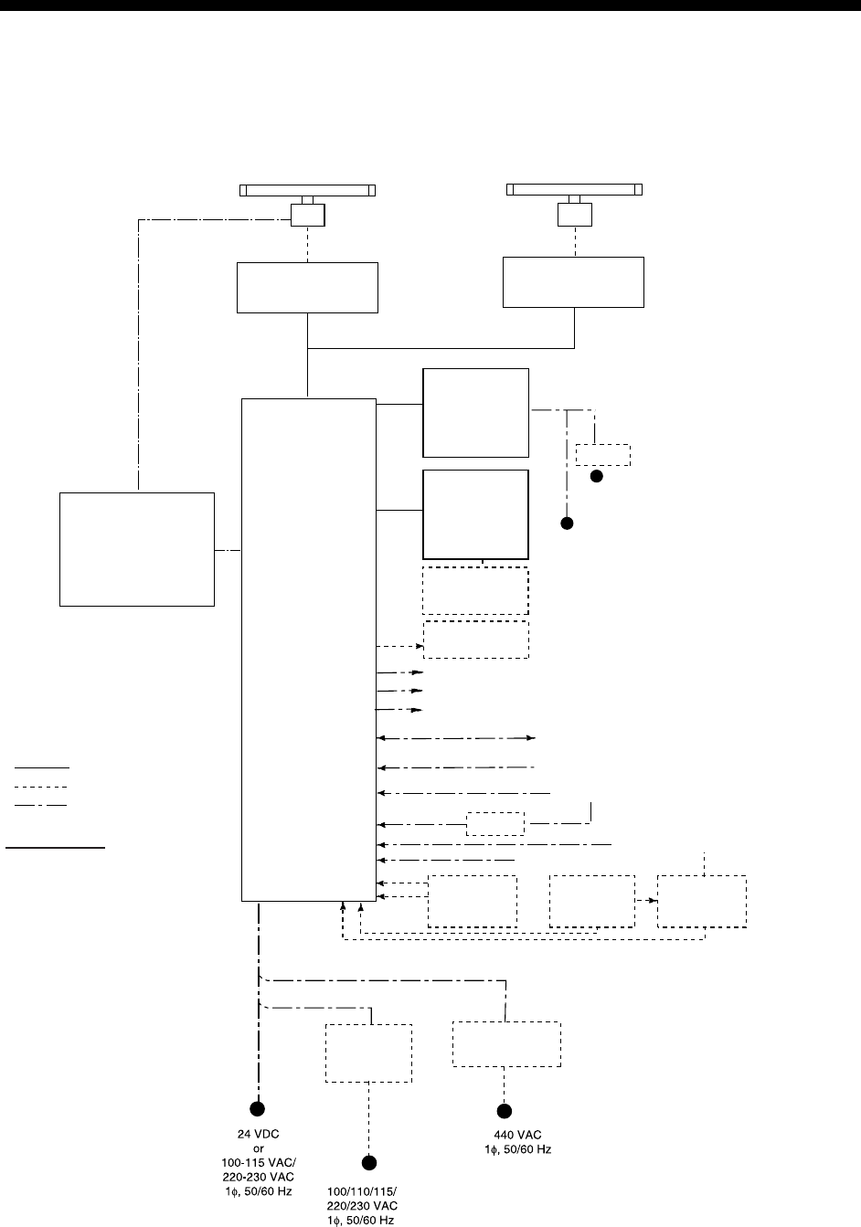
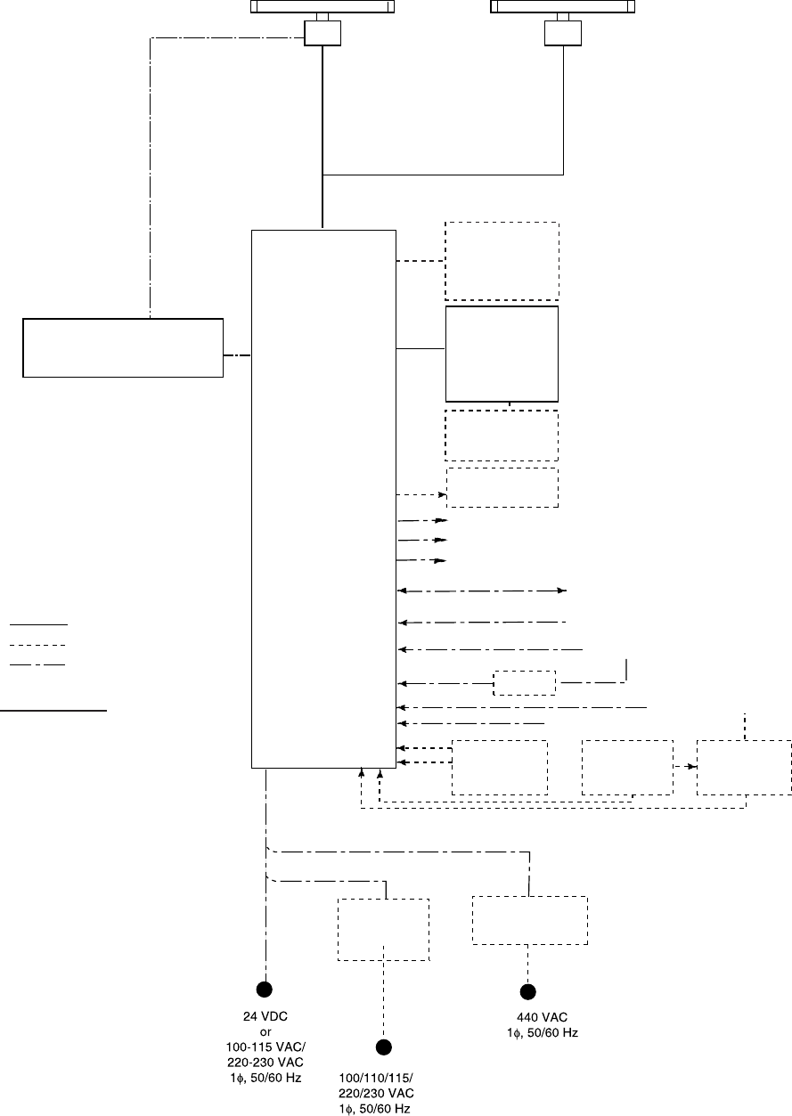
SYSTEM CONFIGURATION
See page xvii for detailed information about antenna units and radiators.
With FURUNO-supplied monitor
ANTENNA UNIT
(Performance Monitor PM-51* built in)
TRANSCEIVER UNIT
RTR-082
For FAR-2837SW
FAR-2137S/2837S/2837SW
PROCESSOR UNIT
RPU-013
FAR-2117/2127/2817/2827/2827W
Waveguide or
Coax cable
(For FAR-2837SW)
VDR
External Monitor
Sub Display
Alarm
MONITOR UNIT
MU-190/201CR
(FAR-21x7)
or
MU-231/231CR
(FAR-28x7)
CONTROL UNIT
RCU-014
(Keyboard)
or
RCU-015
(Trackball)
Control Unit
RCU-016
(Remote)
24 VDC
or
115/230 VAC
115/230 VAC
RU-3423
24 VDC
Navigator (INS, GPS, etc.)
IEC-61162-1 Serial Data
(Input/Output)
IEC-61162-1 Serial Data
(Input) Speed Log
Gyrocompass
AIS
AD-100
TRANSCEIVER UNIT
RTR-081A
For FAR-2827W
Waveguide
(For FAR-2827W)
: Option
: Dockyard supply
: Standard
Category of Units
Antenna unit: Exposed to weather
All other units: Protected from weather
ANTENNA UNIT
(Performance Monitor PM-31* built in)
Rectifier
RU-3424
RU-1746B-2
Transformer Unit
RU-1803
DC spec
AC spec
Track Control Unit
Memory Card
Interface Unit
CU-200
OR Memory Card
Interface Unit
CU-200 x 2
Switching Hub
HUB-100
HUB has ports for connection of up to 7 processor units
100-230 VAC
POWER SUPPLY UNIT
PSU-007
(For FAR-2137S/2837S)
OR
POWER SUPPLY UNIT
PSU-011*
(For FAR-2827W/2837SW)
* Russian flag only
*
* These monitors have been approved by the IMO,
If a different monitor is to be used, its effective diameter
must meet the applicable Category requirements:
CAT 1: effective diameter 320 mm or higher
CAT 2: effective diameter 250 mm or higher
For installation and operation of other monitor,
see its manuals.
MU-190/201CR for CAT2, MU-231/231CR for CAT1.

SYSTEM CONFIGURATION
xvii
Antenna unit
FAR-2117,
FAR-2117-BB,
FAR-2127,
FAR-2127-BB,
FAR-2827
RSB-096 (24 rpm)
RSB-097 (42 rpm)
FAR-2137S,
FAR-2137S-BB
RSB-098/099 (21/26 rpm, 200 VAC, 3ø, 50 Hz; 220 VAC, 3ø, 60 Hz; 380
VAC, 3ø, 50 Hz, 440 VAC, 3ø, 60 Hz)
RSB-100/101/102 (45 rpm, 220 VAC, 3ø, 50/60 Hz(HSC);
440 VAC, 3ø, /60 Hz(HSC))
FAR-2827W RSB-103 (24 rpm, powered by processor unit)
FAR-2837S Same as FAR-2137S
FAR-2837SW RSB-104/105 (21/26 rpm, 200 VAC, 3ø, 50 Hz; 220 VAC, 3ø, 60 Hz; 380
VAC, 3ø, 50 Hz, 440 VAC, 3ø, 60 Hz)
Radiator
FAR-2117, FAR-2117-BB,
FAR-2127, FAR-2127-BB,
FAR-2827
XN12AF (4 ft), XN20AF (6.5 ft), XN24AF (8 ft)
FAR-2137S, FAR-2137S-BB SN30AF (10 ft), SN36AF (12 ft)
FAR-2827W XN20AF (6.5 ft), XN24AF (8 ft)
FAR-2837S SN30AF (10 ft), SN36AF (12 ft)
FAR-2837SW SN30AF (10 ft), SN36AF (12 ft)
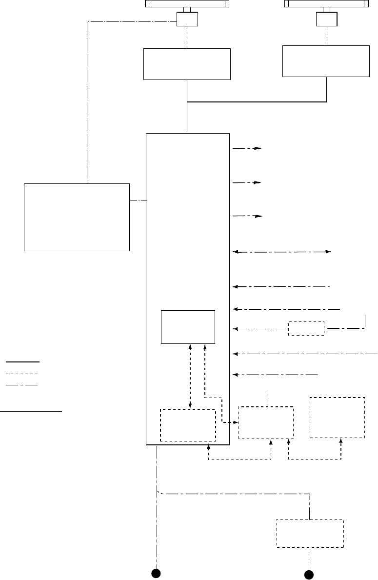
SYSTEM CONFIGURATION
xviii
Blackbox type
ANTENNA UNIT
(Performance Monitor PM-51 built in
FAR-2137S-BB)
FAR-2137S-BB
PROCESSOR UNIT
RPU-013
Sub Display
CONTROL UNIT
RCU-014
(Keyboard)
or
RCU-015
(Trackball)
Control Unit
RCU-016
(Remote)
AIS
: Option
: Dockyard supply
: Standard
Category of Units
Antenna unit: Exposed to weather
All other units: Protected from weather
FAR-2117-BB/2127-BB
ANTENNA UNIT
(Performance Monitor PM-31 built in
FAR-2117-BB, FAR-2127-BB)
Rectifier
RU-3424
RU-1746B-2
Transformer Unit
RU-1803
DC spec
AC spec
VDR
External Monitor
Alarm
Navigator (INS, GPS, etc.)
IEC-61162-1 Serial Data
(Input/Output)
IEC-61162-1 Serial Data
(Input) Speed Log
Gyrocompass
AD-100
Track Control Unit
Memory Card
Interface Unit
CU-200
OR Memory Card
Interface Unit
CU-200 x 2
Switching Hub
HUB-100
HUB has ports for connection of up to 7 processor units
100-230 VAC
POWER SUPPLY UNIT
PSU-007
(For FAR-2137S-BB/2837S-BB)
VGA Monitor
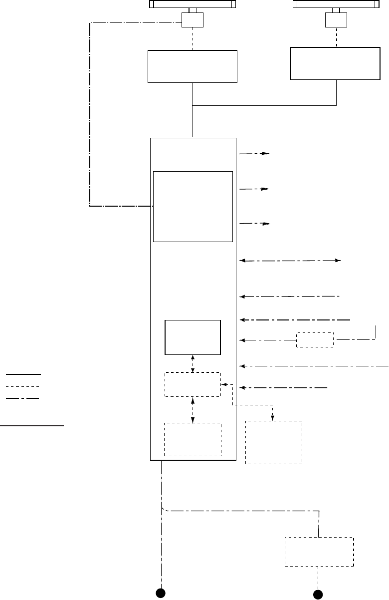
SYSTEM CONFIGURATION
xix
Console type RCN-001/RCN-002
ANTENNA UNIT
(Performance Monitor PM-51 built in)
TRANSCEIVER UNIT
RTR-082
For FAR-2837SW
FAR-2137S/2837S/2837SW
POWER SUPPLY UNIT
PSU-007
For FAR-2137S/2837S
OR
POWER SUPPLY UNIT
PSU-011*
(For FAR-2827W/2837SW)
CONSOLE
RCN-001/002
FAR-2117/2127/2817/2827/2827W
Waveguide or
Coax cable
(For FAR-2837SW)
AIS
Gyrocompass
AD-100
TRANSCEIVER UNIT
RTR-081A
For FAR-2827W
Waveguide
(For FAR-2827W)
: Option
: Dockyard supply
: Standard
Category of Units
Antenna unit: Exposed to weather
All other units: Protected from weather
ANTENNA UNIT
(Performance Monitor PM-31 built in)
100-115 VAC/
220-230 VAC
1φ, 50/60 Hz
Transformer Unit
RU-1803
440 VAC
1φ, 50/60 Hz
AC spec
Alarm
VDR
External Monitor
Navigator (INS, GPS, etc.)
IEC-61162-1 Serial Data
(Input/Output)
IEC-61162-1 Serial Data
(Input) Speed Log
Track Control Unit
Memory Card
Interface Unit
CU-200
Switching Hub
HUB-100
100-230 VAC
PROCESSOR
UNIT
RPU-013
May also
be installed
externally.
OR
Memory Card
Interface Unit
CU-200
(Max. 2 total)
* Russian flag only
SYSTEM CONFIGURATION
xx
Console type RCN-003/RCN-004
ANTENNA UNIT
(Performance Monitor PM-51 built in)
TRANSCEIVER UNIT
RTR-082
For FAR-2837SW
FAR-2137S/2837S/2837SW
CONSOLE
RCN-003/004
FAR-2117/2127/2817/2827/2827W
Waveguide or
Coax cable
(For FAR-2837SW)
AIS
Gyrocompass
AD-100
TRANSCEIVER UNIT
RTR-081A
For FAR-2827W
Waveguide
(For FAR-2827W)
: Option
: Dockyard supply
: Standard
Category of Units
Antenna unit: Exposed to weather
All other units: Protected from weather
ANTENNA UNIT
(Performance Monitor PM-31 built in)
100-115 VAC/
220-230 VAC
1φ, 50/60 Hz
Transformer Unit
RU-1803
440 VAC
1φ, 50/60 Hz
AC spec
Alarm
VDR
External Monitor
Navigator (INS, GPS, etc.)
IEC-61162-1 Serial Data
(Input/Output)
IEC-61162-1 Serial Data
(Input) Speed Log
Track Control Unit
Memory Card
Interface Unit
CU-200
Memory Card
Interface Unit
CU-200
(Max. 2 total)
PROCESSOR
UNIT
RPU-013
Switching Hub
HUB-100
POWER SUPPLY UNIT
PSU-007
For FAR-2137S/2837S
OR
POWER SUPPLY UNIT
PSU-011*
(For FAR-2827W/2837SW)
* Russian flag only

1-1
1. RADAR OPERATION
1.1 Turning on the Power
The [POWER] switch ( ) is located at the left corner of the control unit. Open the
POWER switch cover and press the switch to turn on the radar system. To turn
off the radar, press the switch again. The screen shows the bearing scale and
digital timer approximately 30 seconds after power-on. The timer counts down
three minutes of warm-up time. During this period the magnetron (transmitter
tube) is warmed for transmission. When the timer has reached 0:00, the
indication "ST-BY" appears at the screen center, meaning the radar is now ready
to transmit pulses.
In the stand-by condition, markers, rings, map, charts, etc. are not shown.
Further, TT and AIS are not shown.
In the warm-up and stand-by conditions, ON TIME and TX TIME count in hours
and tenths of hour appear at the screen center.
Note 1: Do not turn the power on directly after it has been turned off. Wait
several seconds before you reapply the power, to be sure the radar
starts up properly.
Note 2: Parameters set on the menus are stored in a non-volatile memory (flash
memory), and are preserved when the power is turned off.
1.2 Transmitter ON
After the power is turned on and the magnetron has warmed up, ST-BY appears
at the screen center, meaning the radar is ready to transmit radar pulses. You
may transmit by pressing the [STBY/TX] key on the full keyboard, or use the
trackball to select the TX STBY box at the bottom left corner of the display then
push the left button (above the trackball). The label at the left-hand side of the
guidance box at the bottom right corner of the screen changes from TX to STBY.
Guidance
box
STBY
/
TX
STBY
TX STBY box
Radar display
1. RADAR OPERATION
1-2
The radar is initially set to previously used range and pulse length. Other
settings such as brilliance levels, VRMs, EBLs and menu option selections are
also set to previous settings.
The [STBY/TX] key (or TX STBY box) toggles the radar between STBY and
TRANSMIT status. The antenna stops in stand-by and rotates in transmit. The
magnetron ages with time resulting in a reduction of output power. Therefore, it
is highly recommended that the radar be set to stand-by when not used for an
extended period of time.
How to stop antenna rotation
Antenna rotation can be stopped. One method is to turn off the antenna switch
on the radar. The other method is to stop rotation from the menu. For how to
stop rotation from the menu, see the installation manual.
Picture freeze
When the picture freezes the picture is not updated. 30 seconds after the picture
freezes, the buzzer sounds, the [ALARM ACK] key blinks and the alarm contact
signal is output. Reset the power to restore normal operation.
Quick start
Provided that the radar was once in use with the transmitter tube (magnetron)
still warm, you can turn the radar into TRANSMIT condition without three
minutes of warm-up. If the [POWER] switch was turned off by mistake or the like
and you wish to restart the radar promptly, turn on the [POWER] switch not later
than 10 seconds after power-off.
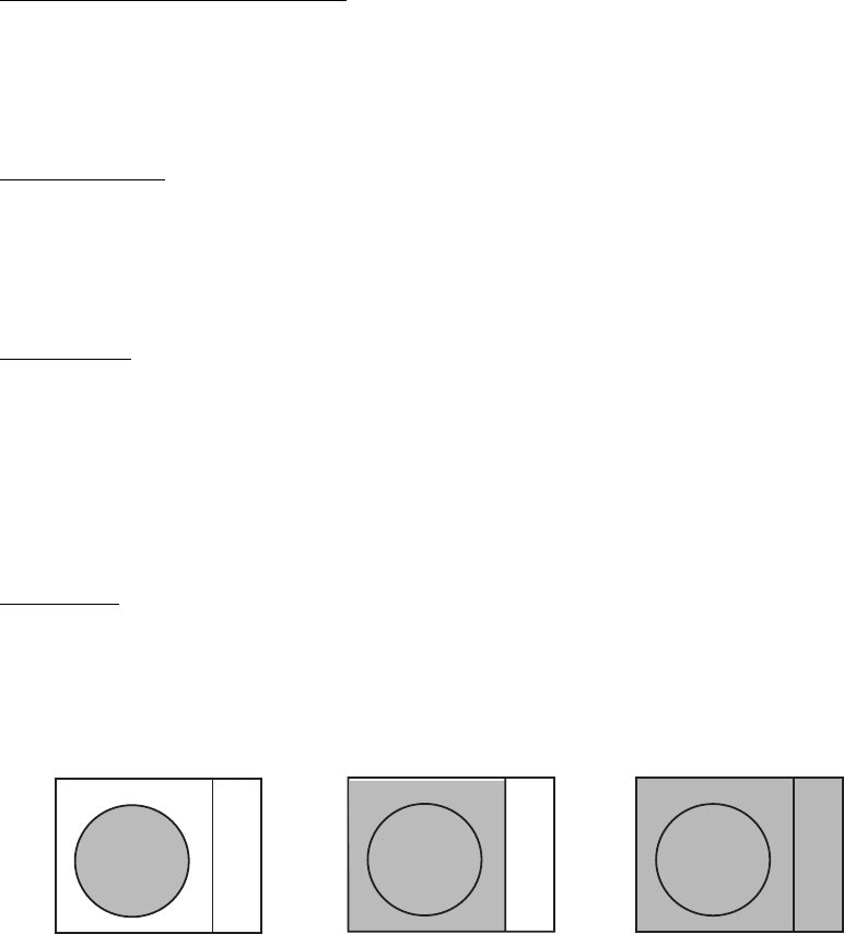
Echo area
The echo display area for the B, C and W types is available in three
configurations: round, wide, and full screen. You can select a configuration with 7
ECHO AREA on the ECHO menu.
Round Wide Full
1. RADAR OPERATION
1-3
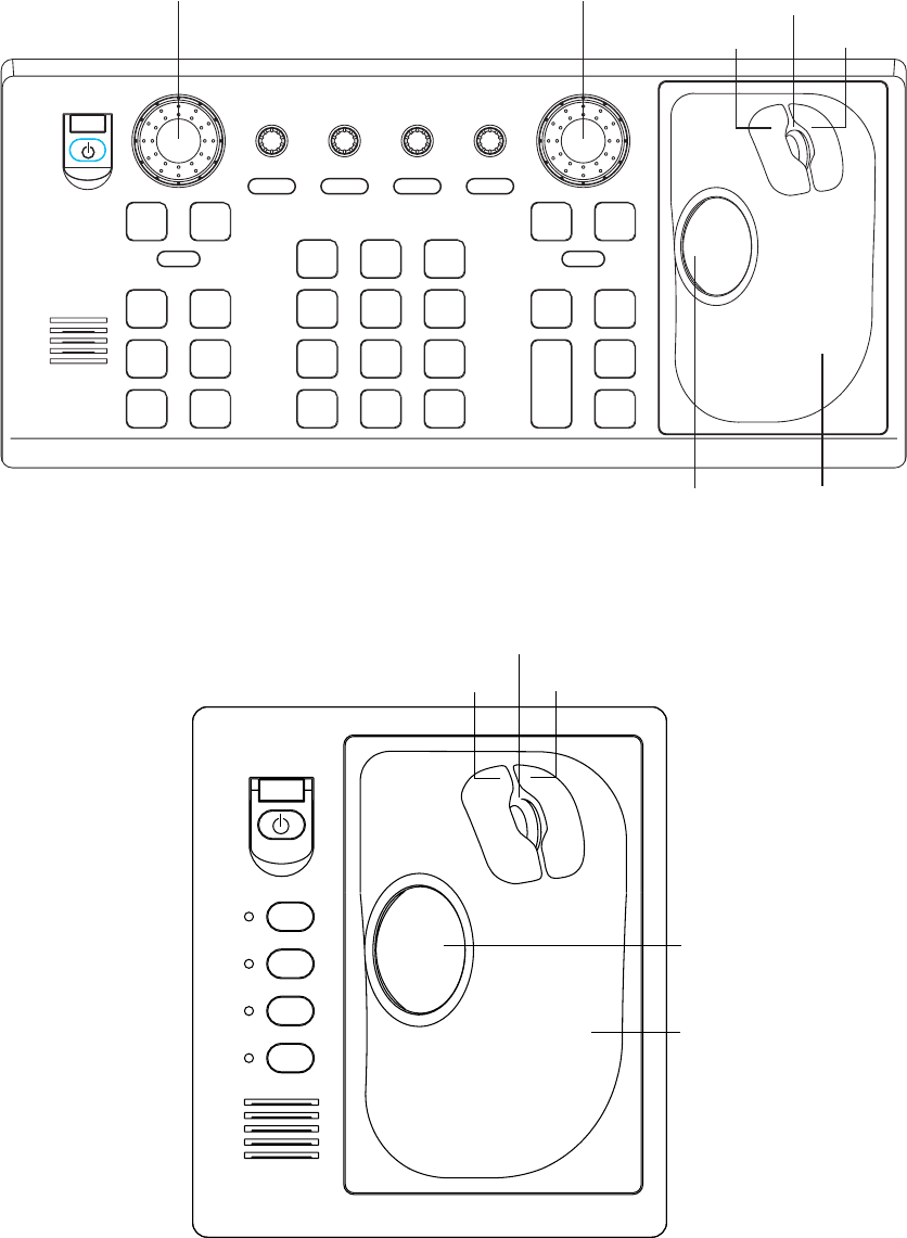
1.3 Control Unit
Two types of control units are available: Control Unit RCU-014 (full keyboard)
and Control Unit RCU-105 (palm control).
ACQ
ON
MENU
OFF
VRM
A/C SEAA/C RAIN
MODE
3
LINE
INDEX
6
OFF
21
HL
CENTER
OFF
45
RESET
CU/TM
OFFSET
EBL
GAIN
TARGET
CANCEL
TARGET
DATA
RANGE
-
+
LIST
TARGET
9
ENTER
MARK
TIME
VECTOR
78
CANCEL
TRAILS
0
MODE
VECTOR
BRILL
BRILL
EBL
F1
OFF
F2
ON
ACK
ALARM
F3 F4
STBY
TX
Trackball
Left button Right button
Scrollwheel
Trackball
Module
EBL rotary control VRM rotary control
Control Unit RCU-014 (full keyboard)
F1
F3
F4
F2
Trackball
Left button Right button
Scrollwheel
Trackball
Module
Control Unit RCU-015 (palm control)

1. RADAR OPERATION
1-4
Control description
Control Description
Control Unit RCU-014 (full keyboard)
POWER Turns the system on and off.
EBL and VRM rotary controls Adjust EBL and VRM, respectively.
EBL ON, EBL OFF Turns the EBLs on and off, respectively.
F1-F4 Execute menu short cut assigned.
ALARM ACK Silences audio alarm.
STBY TX Toggles between stand-by and transmit.
BRILL Adjusts display brilliance.
A/C RAIN Suppresses rain clutter.
A/C SEA Suppresses sea clutter.
GAIN Adjusts sensitivity of the radar receiver.
HL OFF Temporarily erases the heading line while pressed.
EBL OFFSET Enables, disables the offset EBL. In menu operation, switches
polarity from North to South and East to West and vice versa.
MODE Selects a presentation mode.
OFF CENTER Shifts own ship position.
CU/TM RESET • Moves own ship position in 75% radius in stern direction.
• Resets the heading line to 0° in course-up and true motion
modes.
INDEX LINE Turns parallel index (PI) lines on and off.
VECTOR TIME Selects vector time (length).
VECTOR MODE Selects vector mode, relative or true.
TARGET LIST Displays data for all tracked targets (AIS and TT).
CANCEL TRAILS Cancels all target trails. In menu operation it clears a line of
data.
ENTER MARK Enters marks; terminates keyboard input.
VRM ON, VRM OFF Turns the VRMs on and off, respectively.
MENU Opens and closes the MAIN menu; closes other menus.
ACQ Acquires a target for TT after choosing it with the trackball.
RANGE Selects radar range.
TARGET DATA Display or erase target data for TT or AIS target chosen with
trackball. For AIS, changes sleeping target to activated target.
TARGET CANCEL TT: Cancel tracking on target.
AIS: Sleep an activated target.
Control Unit RCU-015 (palm control)
POWER Turns the system on and off.
F1-F4 Execute menu short cut assigned.

1. RADAR OPERATION
1-5
1.4 Main Menu
You may access the MAIN menu from the full keyboard or by using the trackball.
In later sections only the procedure for menu operation by trackball is given.
Main menu operation by keyboard
1. Press the [MENU] key. The MAIN menu appears in the text area at the right
side of the screen.
[MAIN MENU]
1 [ECHO]
2 [MARK]
3 [ALARM]
4 [TT AIS]
5 [PLOTTER]
6 [CARD]
7 [NAV DATA]
8 [NAV LINE WPT]
9 [CUSTOMIZE TEST]
Echo processing functions
Mainly turns markers on/off.
Sets guard alarm functions; outputs alarm signal.
Sets TT and AIS functions.
Chart and track functions
Memory card functions
Turns nav data on/off.
Processes nav lines and waypoints.
Customizes operation; executes diagnostics.
MAIN menu
2. Press the numeral key corresponding to the menu you wish to open. For
example, press the [2] key to open the MARK menu.
[MARK]
1 BACK
2 OWN SHIP MARK
OFF/MIN/SCALED
3 STERN MARK
OFF/ON
4 [PI LINE]
5 ANCHOR WATCH
OFF/ON
0.0NM
6 DROP MARK
OFF/ON
7 [INS MARK] *1
8 EBL OFFSET BASE
STAB GND/STAB HDG/
STAB NORTH
9 [EBL, VRM, CURSOR SET]*2
0 RING
OFF/ON
*
1
[BARGE MARK] depending on installation preset.
*
2
IMO and A types show
9 EBL CURSOR BEARING (REL/TRUE)
MARK menu
3. Press the numeral key applicable to the item
you wish to set.
4. Consecutively press the same numeral key
pressed at step 3 to select appropriate
option then press the [ENTER MARK] key to
confirm your selection.
5. Press the [MENU] key to close the menu.
To clear a line of numeric data:
Use the [CANCEL TRAILS] key.
Switch between plus and minus,
North and South or East and West:
Use the [2] key.
Useful keys in menu operation

1. RADAR OPERATION
1-6
Main menu operation by trackball
1. Use the trackball to select the MENU box at the right side of the screen. The
guidance box at the bottom right corner (see the illustration at the bottom of
the next page for location) now reads "DISP MAIN MENU."
2. Push the left button to display the MAIN menu.
[MAIN MENU]
1 [ECHO]
2 [MARK]
3 [ALARM]
4 [TT
AIS]
5 [PLOTTER]
6 [CARD]
7 [NAV DATA]
8 [NAV LINE
WPT]
9 [CUSTOMIZE
TEST]
Echo processing functions
Mainly turns markers on/off.
Sets guard alarm functions; outputs alarm signal.
Sets TT
and AIS functions.
Chart and track functions
Memory card functions
Turns nav data on/off.
Processes nav lines and waypoints.
Customizes operation; executes diagnostics.
MAIN menu
3. Roll the scrollwheel or trackball to select a menu and push the left button. For
example, select the 2 [MARK] menu.
[MARK]
1 BACK
2 OWN SHIP MARK
OFF/MIN/SCALED
3 STERN MARK
OFF/ON
4 [PI LINE]
5 ANCHOR WATCH
OFF/ON
0.0NM
6 DROP MARK
OFF/ON
7 [INS MARK] *1
8 EBL OFFSET BASE
STAB GND/STAB HDG/
STAB NORTH
9 [EBL, VRM, CURSOR SET]*2
0 RING
OFF/ON
*
1
[BARGE MARK] depending on installation preset.
*
2
IMO and A types show
9 EBL CURSOR BEARING (REL/TRUE)
MARK menu
4. Use the trackball to select a menu item and push the left button.
5. Roll the scrollwheel to select an option and push the left button to validate
your selection.
6. Push the right button consecutively to close the menu. (Several pushes may
be necessary depending on the menu used.)
Note: Hereafter all menu procedures are described using the trackball module
(trackball, scrollwheel, buttons). For sake of brevity we write, "Select [menu item]
(or [menu option])" where you roll the scrollwheel and push the left button (or
scrollwheel) to complete a task on the menu.
1. RADAR OPERATION
1-7
1.5 Operation by the On-Screen Boxes
All radar functions can be accessed by using the trackball alone. This is done by
choosing the appropriate on-screen box with the trackball and operating the
trackball module to select item and option. (See section 1.9 for location of all
on-screen boxes.) On-screen boxes come in two varieties: Function selection
and function selection w/pop-up menu. On-screen boxes of the latter type have
"►" at the right side of their boxes, as in the MARK box shown below.
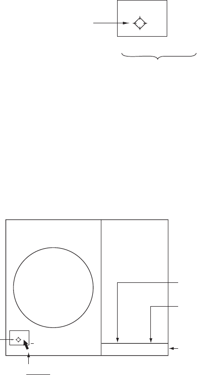
To operate the radar using on-screen boxes, do the following:
1. Use the trackball to place the trackball marker inside the box desired.
Note: The trackball marker changes its configuration according to its location.
It is an arrow when placed outside the effective display and a cursor
(+) when inside the effective display. See the illustration on the next
page for further details.
For example, select the MARK box, which is at the bottom left corner.
MARK
Mark type last
selected, mark
number
-> +
162.5°T 11.7 NM
Bearing and range from
own ship to mark
1
MARK box
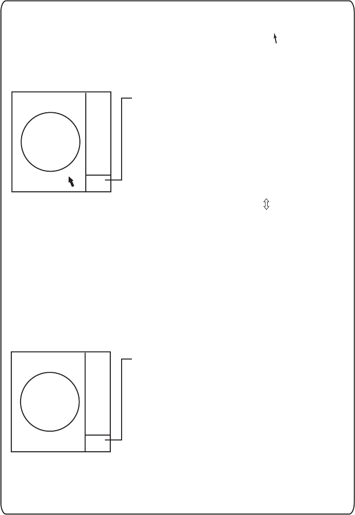
When a box is correctly selected, its color changes from green to orange and
the guidance box at the bottom right corner shows operational guidance. The
operational guidance shows the function of the left and right buttons, with a
diagonal line separating the information. For the MARK box, for example, the
operational guidance is "MARK SELECT / MARK MENU." In this case you
would push the left button to select a mark or push the right button to open
the MARK menu.
Guidance box
MARK
SELECT
MARK
MENU
/
Function of left button
Function of right button
Arrow
For choosing
on-screen box
MARK
MARK Box
> +
1
Guidance box (Example: guidance for MARK box)
1. RADAR OPERATION
1-8
Trackball marker location and guidance box indication
The trackball marker is either a cursor (+) or an arrow ( ) depending
on whether it is within or outside the display area, respectively.
Further, the indication in the guidance box changes according to
trackball marker location.
Trackball marker is within
effective display area:
The trackball marker is
a cursor.
+
Guidance box reads
"TARGET DATA & ACQ / CURSOR MENU."
In this condition you may access cursor-operated
functions, by hitting the left button for direct
selection of function or the right button to choose
desired functions from the CURSOR menu. For
further details about the CURSOR menu,
see section 1.6.
Trackball marker is out of
effective display area
(incl. text area) and
not selecting a box:
The trackball marker is
an arrow
Guidance box reads
"JUMP CURSOR / DISP MENU."
Push the left button to choose the on-screen
box closest to the arrow or push the right
button to display the MAIN menu.
To choose boxes successively, push the wheel
when the guidance box reads as above.
Then, the nearest box is selected and marked
with the double-ended arrow ( ) and the
guidance box reads
"JUMP FORWARD / JUMP BACKWARD."
Hit the left button to go to the box below or
adjacent to the currently selected box or hit
the right button to go to the box above or
adjacent to the currently selected box.
Continue pushing a button to choose boxes
successively. This is convenient for operation
under heavy pitching and rolling. To cancel this
feature, push the wheel when the guidance box
reads as above.
2. Push the left button (or roll the scrollwheel depending on the box) until the
desired option is displayed in the box.
Note: When you selected an on-screen box’s option by rolling the
scrollwheel, the box and its contents turn light-blue. This simply
indicates that the selected setting is different from the currently active
setting. To change the setting, push the scrollwheel or the left button. If
neither the scrollwheel nor the left button is pushed within about 30
seconds after operating the scrollwheel, the previous setting is
automatically restored.

1. RADAR OPERATION
1-9
3. The pop-up menu attached to the MARK box is the MARK menu. To open the
menu, push the right button. The menu opens in the text area at the right side
of the screen.
[MARK MENU]
1 ORIGIN MARK STAB
GND/SEA
2 MARK KIND
ORIGIN MARK(No. )/
ORIGIN MARK(SYM)/
MAP MARK/
WP 1~50/
WP 51~ 100/
WP 101~150/
WP 151~198/
OWN SHIP SHAPE
8 MARK POSN
CURSOR/OS/L/L
00°000.00 N
000°000.00 E
9 MAP DISPLAY
OFF/ON
0 MAP MARK COLOR*
RED/GRN/BLU/YEL/
CYA/MAG/WHT
* Not available on IMO
or A type
MARK menu
Note:Any menu may be operated from the full keyboard or with the trackball,
or a combination of the two in case of Control Unit RCU-014. Note
that in later sections only the procedure for menu operation by
the trackball is given.
4. Select item desired. Selected item is initially shown in reverse video and
changes to normal video and circumscribed when the scrollwheel or the left
button is pushed.
5. Select option desired. Selected option is initially shown in reverse video and
changes to normal video and circumscribed when the scrollwheel or the left
button is pushed.
6. Push the right button to close the menu. (On some menus several presses of
the right button are required to close the menu.)

1. RADAR OPERATION
1-10
[CURSOR MENU]
2
TARGET DATA & ACQ/
TARGET CANCEL/
TT TGT DATA & ACQ/
TARGET TRACK ON*
1
/
TARGET TRACK OFF*
1
/
REF MARK/
EBL OFFSET/
OFFCENTER/
ZOOM/
MARK DELETE/
OWN TRACK DELETE/
TGT TRACK DELETE*1/
CHART ALIGN
TRAIL ERASER*
1
, *
2
/
8
9 CURSOR*
1
, *
2
SMALL/LARGE
*
1
Not available on IMO type
*
1
Not available on A type
1.6 Cursor Menu
Functions that require the use of the cursor, such
as EBL offset and zoom, may be activated directly
from the guidance box or from the CURSOR menu,
either method with the cursor inside the effective
display area. Below is the procedure for choosing a
cursor-related function from the CURSOR menu. In
later sections only the procedure for selection from
the guidance box is given.
1. Put the cursor inside the effective display area.
2. Roll the scrollwheel to show "TARGET DATA &
ACQ / CURSOR MENU" in the guidance box.
3. Push the right button to show the CURSOR
menu.
4. Select "2" then push the left button.
5. Select function desired then push the left
button.
Note: For operation from the keyboard, you may
press the [2] key to select a function in
top-to-bottom order or the [8] key to select in reverse order.
Cursor Menu item Description
TARGET DATA & ACQ TT: Acquires target; displays data for selected tracked target.
AIS: Activates sleeping AIS target; display data for selected AIS
target.
TARGET CANCEL TT: Cancels tracking on selected tracked target.
AIS: Sleeps selected AIS target.
TT TARGET DATA & ACQ Acquires selected echo as tracked target.
TARGET TRACK ON Turns track for TT/AIS on.
TARGET TRACK OFF Turns track for TT/AIS off.
REF MARK Inscribes reference mark, for target-based speed input.
EBL OFFSET Offsets EBL to measure range and bearing between two targets.
OFF CENTER Shifts screen center to selected location.
ZOOM Zooms selected location.
MARK DELETE Deletes selected mark (plotter mark, origin mark or waypoint
mark).
OWN TRACK DELETE Deletes own ship’s tracks.
TGT TRACK DELETE Deletes other ship’s tracks.
CHART ALIGN Aligns chart with radar picture.
TRAIL ERASER Erases trails. (A, B and C types)
CURSOR SIZE Selects cursor size. (A, B and C types)
6. The guidance box shows "XX / EXIT." (XX = function selected). Use the
trackball to put the cursor where desired.
7. Push the left button to execute the function selected at step 5.
8. To quit the function selected, push the right button when the guidance box
shows "XX / EXIT." (XX = function selected at step 5)
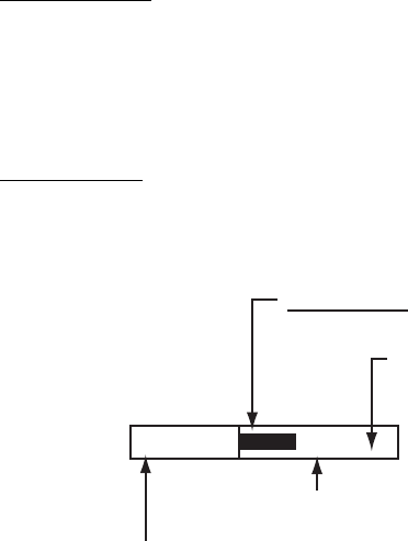
1. RADAR OPERATION
1
-
11
1.7 Monitor Brilliance
The brilliance of the entire screen should be adjusted according to lighting
conditions. Monitor brilliance should be adjusted before adjusting relative
brilliance levels on the BRILL menu to be explained later.
Note: The brilliance of a commercial monitor cannot be adjusted from the radar.
See the owner’s manual of the commercial monitor for how to adjust its
brilliance.
By keyboard
Operate the [BRILL] control on the control unit to adjust brilliance. Turn it
clockwise to increase brilliance; counterclockwise to decrease brilliance. Watch
the BRILL box (see illustration below) to know current brilliance level.
By trackball
1. Use the trackball to place the arrow on the brilliance level indicator in the
brilliance level indication box at the bottom left corner of the screen.
BRILL1
Place arrow inside box
to adjust screen brilliance.
Brilliance bar
Shows brilliance level.
26
Brilliance level
Brillance, color set no.
(For details, see para. 1.50.)
Brilliance level indicator
2. Roll the scrollwheel downward to increase brilliance or roll it upward to
decrease brilliance. The length of the brilliance bar increases or decreases
with operation of the scrollwheel.
Note: If nothing appears on the screen in stand-by when using Control Unit
RCU-015 (palm control), press and hold down one of the keys F1-F4* to
raise the brilliance to level "50".
*Key set for other than USER DEFAULT. See section 1.36.2.

1. RADAR OPERATION
1-12
1.8 Display Modes
This radar has the following display modes:
• IMO, A type: Radar, Radar + Plotter, Anchor (Watch)
• B, C, W type: Radar, Radar + Plotter, Plotter
Select a display mode as below. Note that a display mode cannot be selected
when the menu is open.
1. Use the trackball to place the arrow in the DISPLAY MODE box at the top of
the screen.
DISPLAY
XX* * XX = display mode
DISPLAY MODE box
2. Push the left button to select appropriate mode.
Radar: Radar display
+Plotter Radar display, plotter display
Plotter: Plotter display
Anchor watch: Plotter display
Note: The radar echo related boxes (STBY/TX, PI line, target alarm, etc.) are
inoperative in the anchor watch and plotter modes.
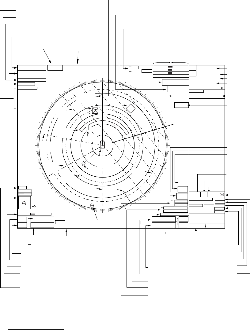
1. RADAR OPERATION
1-13
1.9 On-Screen Boxes and Markers
6
HEAD UP TB RM
MENU
HDG
000.0°T
ANT 1 X-BAND
PULSE S1
PICTURE4
IR OFF
ES OFF
EAV OFF
AUTO RAIN
OFF
NM
/1 DISPLAY
RADAR GAIN
SEA AUTO
RAIN
TUNE AUTO
34°40. 649 N
135°18. 303 E
+
SPD
0.0kn
TT AIS
FILT
SB
0.0kn
COG
00.0°T
SOG
0.0kn
OS POSN
VECTOR REL 30M
3M
CPA LIMIT 0. 5NM 22MIN
TARGET
LIST
CU/TM
RESET
ALARM
ACK
TARGET
DATA & ACQ CURSOR
MENU
AZ1
PI 1
MARK
032. 0°T
190.0°T, 5.75NM
+
BRILL1
HL
OFF EBL1
>280.9°T<
EBL2
240. 8°T
TX
STBY
5. 60NM
ON
AZ2
ALARM1
ALARM2
VRM1
>3.682NM<
VRM2
5.221NM
WATCH
11 : 28
000 010 020
030
040
050
060
070
080
090
100
110
120
130
140
150
160
170
180
190
200
210
220
230
240
250
260
270
280
290
300
310
320
330 340 350
OFF
North
Marker
Stern
Marker
TRUE-S TRAIL OFF
AIS DISP Box
25
22
19
CHART
ALIGN
Chart Align ON
DISP
CPA AUTO ACTIVATE
OFF
LOST TARGET ALARM
OFF
DROP1
Drop
Mark
229.8°T 4.532NM
PAST POSN REL 3M
TTG 312.3°R
00:11 1.864NM
<
AtoN
DROP2
BT
LOG
GAIN Setting
A/C SEA Setting
A/C RAIN Setting
TUNING Setting
Position
MENU Box
AIS Message Arrvl
Guidance Box
WATCH Box
EBL2 Box
EBL1 Box
TX/STBY Box
HL OFF Box
BRILL Box
MARK Box
Bearing and range to mark
PI line number
PI line orientation
PI line interval
VRM2 Box
TT ACQ MODE Box
SET and DRIFT Boxes
DISPLAY
MODE
Box
RANGE Box
PRESENTATION MODE Box
ANTENNA Box
PULSELENGTH Box
PICTURE Box, Main Picture Settings
0. 0knDRIFT
000. 0°TSET
VRM1 Box
(w/TTG)
TRAIL MODE Box
TARGET ALARM Box
AZ (Acquisition Zone) Box
TARGET LIST Box
Heading
Speed, Source
Heading
Line
Acquisition
Zone Cursor
No. 2
EBL
No. 1
EBL
No. 1
VRM
No. 2
VRM
Range
Rings
PI
Line
CU/TM
RESET,
ALARM ACK
Box
ZOOM or TT
DATA B OX
(See next page.)
ALERT BOX
(See next page.)
Origin Mark
Own Ship
Marker
Log Speed
Course over Ground
Speed over Ground,
Source
34°40.00N
135°24.00E
DGPS
ZOOM, TT,
or AIS DATA BOX
(See next page.)
TT,
AIS DATA BOX
26
TRIAL OFF
Trial Maneuver (Elapsed time shown
when trial maneuver is active.)
REF POINT
ANT
REF POINT
Setting
Drop Mark
data LOST TARGET Box
CPA AUTO Box
CPA LIMIT Box
PAST POSN Box
TT VECTOR Box
Range, Bearing and TTG to cursor position
ASSOCIATION ON/OFF
00:00
+
AIS
Base
Station
Cursor Position Box
MAP
ON
ORIGIN*
* W-type only. Denotes mark
selection:
ORIGIN: Origin mark
MAP: Map mark
OS: Own ship shape
GPS
Markers and indications
Viewing distance
The optimal viewing distances for the radar display units are as follows:
- MU-170C: 920 mm
- MU-201CR: 1080 mm
- MU-231CR: 1200 mm
- MU-190: 1020 mm
- MU-231: 1200 mm
Note: Magnetic fields do not affect the picture.
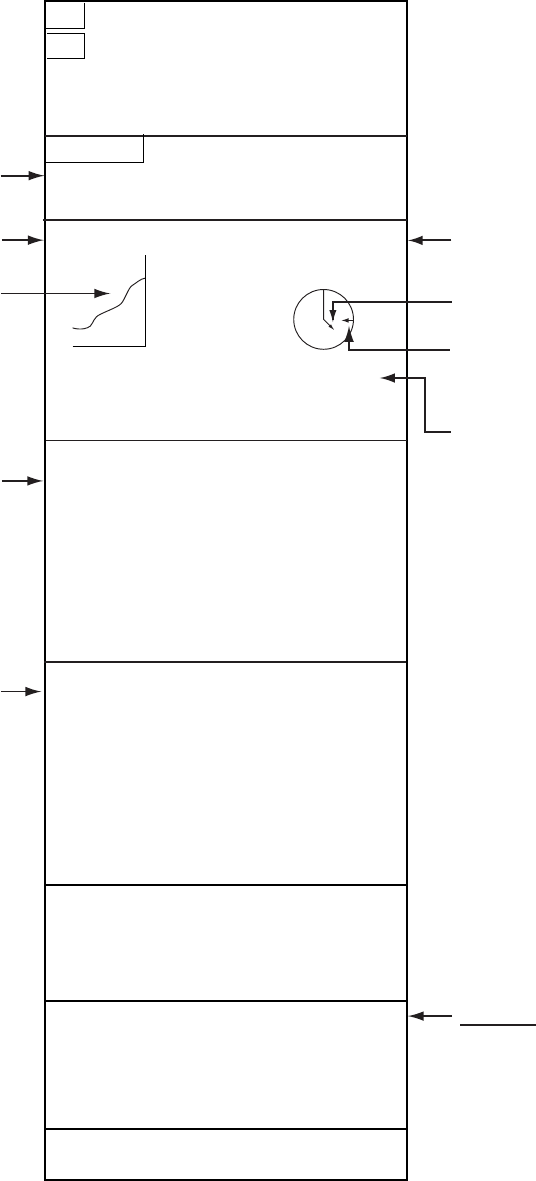
1. RADAR OPERATION
1-14
Guidance Box
TT, AIS Functions Box
TT TARGET
No. 42
BRG 25.5°T
RNG 3.4NM
R COG 264.0°T
R SOG 12.3KN
CPA 2.9NM
TCPA 12.2MIN
BCR 1.7NM
BCT 20MIN
20
40
60
80
100
-30 20 10
DEPTH 22.30 m
HDG
242.2°T
SPD
9.9kn BT
SB
0.1kn
COG
30.2°T
SOG
10.2.2kn
OS POSN
34°40.00N
135°24.00E
DGPS
Wind Speed and Angle*
(True or Relative angle)
Electronic Position-fixing
System and position*
Heading is TRUE
(variation-corrected gyro or
magnetic heading)
Speed data is LOG, MAN, etc.,
showing sensor and types.
TT Target Data
(See Chapter 3.)
* GPS, DGPS,
PPS, RTK, FRTK,
DR. PPS, RTK
and FRTK require
GGA sentence.
Tide relative to North,
full scale 10 kn
Wind direction relative to
own ship heading
S
WE
N
Depth
Depth Echogram
(See section 1.41.)
Alert Box
Messages for sensor error,
system error, alarms and
warning.
See section 1.44 for details.
Current speed and direction*
Water temperature, TTG,
WPT no., range and bearing
to waypoint
Date, time
* Referenced to ship's heading
(relative) in head-up,
head-up TB and course-up.
Referenced to North (true) in
north-up and true motion.
For presentation mode
description, see section 1.12.
EPFS shall meet the requirements
of the IMO resolution MSC.112(73).
CURRENT 2.3kn 69.9
°R
TEMP 16°C TTG 00:00:00
WPT001 6.5NM 35.2°R
DATE OCT/25/03 10:00 UTC
TT Target Data
(or Zoom)
Zoom display appears
in nav data box when
nav data is turned off.
WT
MAN
GPS
- - - - - SYSTEM ERROR - - - - -
VIDEO
- - - - - - - - - WARNING - - - - - - - -
FORMAT CARD DATA
TRUE 15.4 m/s
WIND 159.9°T
Data fields

1. RADAR OPERATION
1-15
1.10 Tuning the Receiver
1.10.1 Choosing the tuning method
The tuning method can be selected with the TUNE box at the top of the screen.
1. Select the TUNE box (TUNE AUTO or TUNE MAN) at the top of the screen.
TUNE AUTO
Place arrow inside box
to adjust tuning, when
TUNE MAN is selected.
Tuning method (AUTO or MAN)
Tuning bar
Tuning level
TUNE box
2. Push the left button or scrollwheel to display TUNE AUTO or TUNE MAN as
appropriate.
3. If you used the scrollwheel to select tuning method, push the scrollwheel or
the left button to change setting.
1.10.2 Initializing tuning
Automatic tuning is initialized during the installation. However, if you feel that
automatic tuning is not working properly try re-initializing it as follows:
1. Left-click the MENU box to open the menu.
2. Select 1 [ECHO].
[ECHO]
1 BACK
2 2
ND
ECHO REJ
OFF/ON
3 TUNE INITIALIZE
4 PM*
1
OFF/ON
5 SART
OFF/ON
6 WIPER
OFF/1/2
7 ECHO AREA*
2
CIRCLE/WIDE/ALL
*1
Not available on FAR-2157/2167DS
*2
Not available on IMO or A type
8 [PICTURE SELECT]
9 STC RANGE
+00
ECHO menu
3. Select 3 TUNE INITIALIZE. (For operation from the keyboard, press the
[ENTER MARK] key.) "WARNING – TUNE INITIALIZE" appears in the Alert
Box during the initialization.
4. Push the right button twice to close the menu.

1. RADAR OPERATION
1-16
[HDG MENU]
1 HDG SOURCE
AD-10/SERIAL
2 GC-10 SETTING
000.0°
1.10.3 Automatic tuning
Select automatic tuning following section 1.10.1. The TUNE box shows TUNE
AUTO.
1.10.4 Manual tuning
1. Select the 48-mile range from the RANGE box. Push the left button to lower
the range; the right button to raise the range.
2. Select manual tuning following the procedure in section 1.10.1.
3. Use the trackball to place the arrow on the tuning bar area in the TUNE box.
4. Roll the scrollwheel to adjust tuning. The best tuning point is where the bar
graph swings maximum. The arrow below the bar graph shows tuning control
position; not the tuning condition.
1.11 Aligning Heading with Gyrocompass
With connection of a gyrocompass, ship's heading is displayed at the right side
of the screen. Turn on the radar and match the on-screen GYRO readout with
the gyrocompass reading as shown below. Once you have set the initial heading
correctly, resetting is not usually required. This alignment is not necessary for
the FURUNO SC-60/120 Satellite Compass.
1. Right-click the HDG box at the top right corner of the screen.
HDG menu
2. Roll the scrollwheel downward to select GC-10 SETTING.
Note: If the heading source selected is not suitable change it at 1 HDG
SOURCE to match your heading source.
3. Roll the scrollwheel to set the heading. (For entry through the keyboard, use
the numeric keys.)
4. Push the scrollwheel to finish.
5. Push the right button to close the menu.

1. RADAR OPERATION
1-17
1.12 Presentation Modes
This radar has the following presentation modes:
Relative Motion (RM)
Head-up: Unstabilized
Head-up TB: Head-up with compass-stabilized bearing scale (True Bearing)
where the bearing scale rotates with the compass reading.
Course-up: Compass-stabilized relative to ship’s orientation at the time of
selecting course-up.
North-up: Compass-stabilized with reference to north
Stern-up: The radar image is rotated 180°. Graphics and relative and true
bearings are also rotated 180°.
True Motion (TM)
Land objects and sea are stationary. Requires compass and speed data.
1.12.1 Choosing presentation mode
By keyboard
Press the [MODE] key consecutively to select presentation mode desired. The
PRESENTATION MODE box shows the current presentation mode. (See the
illustration below.)
By trackball
Left-click the PRESENTATION MODE box at the top left corner of the screen to
select a presentation mode.
HEAD UP RM*
* = Other modes:
STERN-UP, HEAD UP TB RM, COURSE UP RM,
NORTH UP RM, NORTH UP TM
PRESENTATION MODE box
Loss of gyrocompass signal
When the compass signal is lost, "GYRO" appears in red in the Alert Box, the
presentation mode automatically becomes head-up, and TT and AIS targets,
map and chart are erased. After restoring the compass signal, "HEADING SET"
appears in the Alert Box. Then, stop the alarm with the [ALARM ACK] key or the
ALARM ACK box and check the GYRO data.
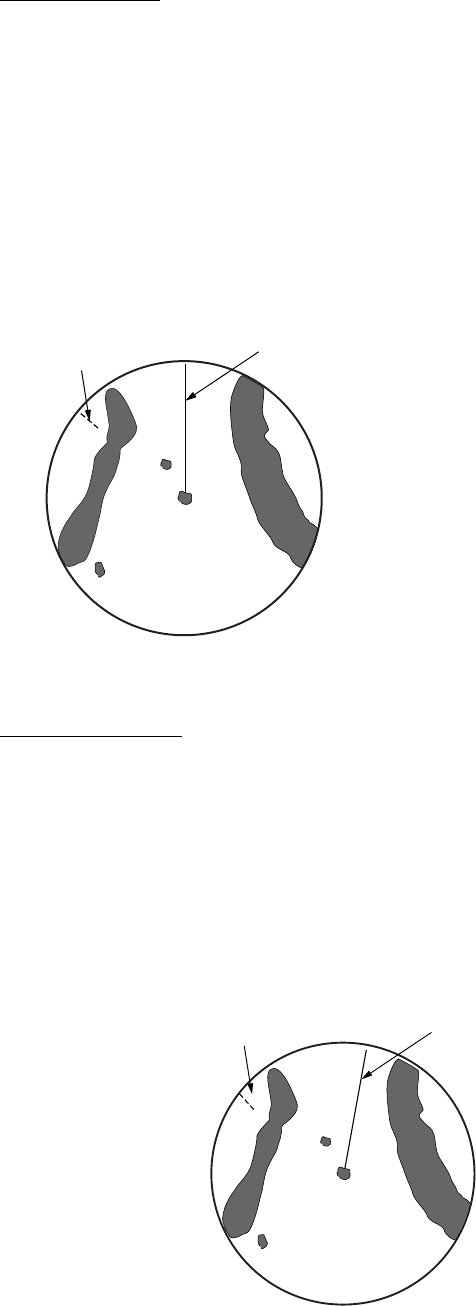
1. RADAR OPERATION
1-18
1.12.2 Description of presentation modes
Head-up mode
The head-up mode is a display in which the line connecting own ship and the top
of the display indicates own ship’s heading.
The target pips are painted at their measured distances and in their directions
relative to own ship’s heading.
A short line on the bearing scale is the north marker indicating heading sensor
north. A failure of the heading sensor input will cause the north marker to
disappear and the readout to show ***.*° and the message HDG SIG MISSING
appears in red at the lower-right corner of the screen.
Heading Line
North Marker
Note: When display is off-centered,
the heading mark appears at 000 degrees.
Head-up mode
Course-up mode
The course-up mode is an azimuth-stabilized display in which a line connecting
the center with the top of the display indicates own ship’s intended course
(namely, own ship’s previous heading just before this mode has been selected).
Target pips are painted at their measured distances and in their directions
relative to the intended course, which is maintained at the 0-degree position. The
heading line moves in accordance with ship’s yawing and course change. This
mode is useful to avoid smearing of picture during course change.
Heading Line
North Marker
Course-up mode

1. RADAR OPERATION
1-19
Head-up TB (True Bearing) mode
Radar echoes are shown in the same way as in the head-up mode. The
difference from normal head-up presentation lies in the orientation of the bearing
scale. The bearing scale is heading sensor stabilized. That is, it rotates in
accordance with the heading sensor signal, enabling you to know own ship’s
heading at a glance.
This mode is available when the radar is interfaced with a gyrocompass.
If the gyrocompass fails, the bearing scale returns to the state of head-up mode.
North-up mode
The north-up mode paints target pips at their measured distances and in their
true (heading sensor) directions from own ship, north bearing maintained at the
top of the screen. The heading line changes its direction according to the ship’s
heading. Requires heading signal.
If the compass fails, the presentation mode changes to head-up and the north
marker disappears. Also, the HDG indication shows ***.*°. And the message
HDG SIG MISSING appears in red at the lower-right corner of the screen.
Heading Line
North Marker
North-up mode
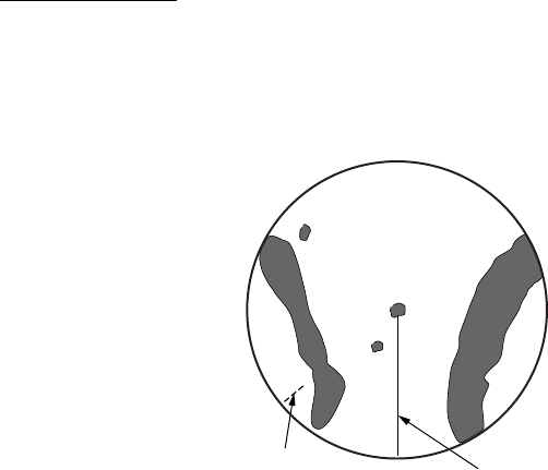
1. RADAR OPERATION
1-20
Stern-up mode
The stern-up mode rotates the head-up mode picture, relative and true bearings
and display graphics 180°. This mode is useful on dual-radar tugboats when
backing up; one radar shows head-up and another shows stern-up. To enable
the stern-up mode, turn on STERN-UP on the 7 OPERATION menu.
Heading Line
North Marker
Stern-up mode
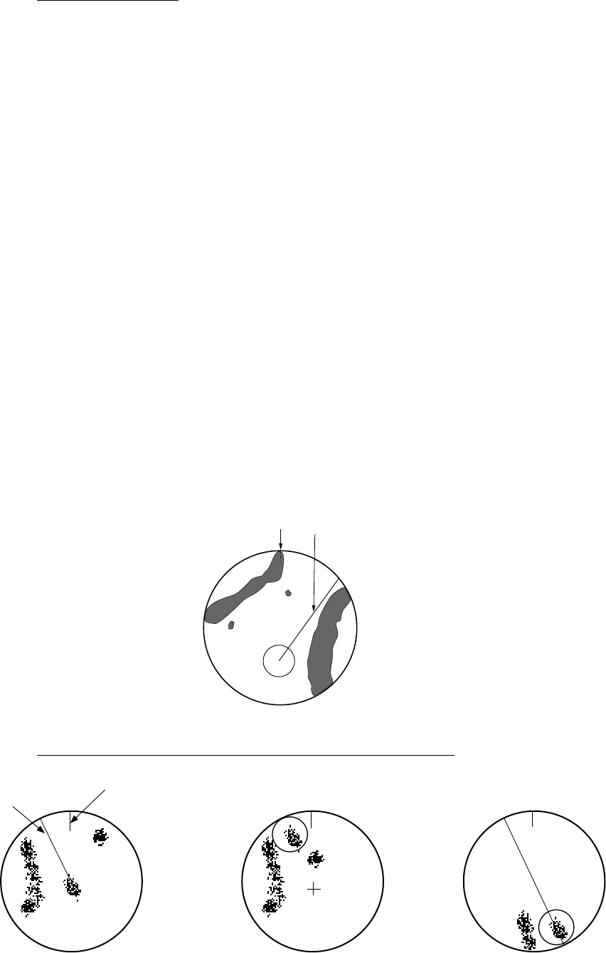
1. RADAR OPERATION
1-21
True motion mode
Own ship and other moving objects move in accordance with their true courses
and speed. In ground stabilized TM, all fixed targets, such as landmasses,
appear as stationary echoes. In the sea stabilized TM without set and drift inputs,
the landmass can move on the screen. Note that true motion is not available on
the 72 nm (non-IMO type only) or 96 nm range scale. If COG and SOG (both
over the ground) are not available on TM mode, enter the set (tide direction) and
drift (tide speed) manually referring to the Tide Table.
When own ship reaches a point corresponding to 50% of the radius of the
display, own ship position is automatically reset to a point of 75% radius opposite
to the extension of the heading line passing through the display center. You may
also reset the own ship symbol manually by pressing the [CU/TM RESET] key,
or left-clicking the CU/TM RESET box at the bottom right corner of the display.
If the heading sensor fails, the mode is changed to the head-up and the north
marker disappears. The HDG readout shows ***.*° and the message HDG SIG
MISSING appears in red at the lower-right corner of the screen.
Note: A part of the bearing scale is drawn differently depending on antenna
reference position.
ANT: Bearing scale interval is different when display is offcentered.
CONN: A part of the bearing scale is not displayed if the conning position is not
within the radar display area.
Heading Line
North Marker
True motion mode
Automatic resetting of own ship mark in true motion mode
Heading
line
North
marker
(a) True motion
is selected
(b) Own ship has reached a
point 75% of display radius
(c) Own ship is automatically
reset to 75% of radius

1. RADAR OPERATION
1-22
[SPEED MENU]
1 SHIP SPEED
LOG(BT)/LOG(WT)/
GPS/MANUAL/REF
2 MANUAL SPEED
0.0kn
3 SET DRIFT
OFF/ON
1.13 Entering Own Ship's Speed
The TT and azimuth stabilized presentation modes require own ship speed input
and compass signal. The speed can be entered from a log (STW) or GPS (SOG)
or manually on the menu. Note that FURUNO GPS Navigator GP-90 provides
COG and SOG.
1.13.1 Automatic speed input by log or GPS navigator
1. Right-click the SPD box at the top right corner of the screen.
SPEED menu
2. Select 1 SHIP SPEED.
3. Select the appropriate source for automatic speed input then push the left
button.
LOG (BT): Log, speed over ground (SOG). Note that a log cannot
produce BT (Bottom Tracking) speed in deep waters without
set and drift entry.
LOG (WT): Log, speed thru water (STW)
GPS: Speed input by GPS navigator
MANUAL: Manually input speed
REF: Echo-referenced speed input
4. Push the right button to close the menu.
Notes on speed input
• IMO Resolution A.823(19) for TT recommends that a speed log to be
interfaced with a TT should be capable of providing through-the-water speed
(forward speed).
• Be sure not to select a LOG option when a speed log is not connected. If the
log signal is not provided, the ship speed readout at the top of the screen will
be blank. In the event of a log error, enter speed manually.
• The SPD is shown as "*.* kn" and the label "LOG" (in red) appears and the
alarm buzzer sounds if no log signal is present for 30 s.
• With the serial speed inputs and SOG selection, if the type of data is changed
from SOG to STW the label "LOG" (in red) appears and the alarm buzzer
sounds.

1. RADAR OPERATION
1-23
• On the IMO type with AIS in use, LOG(WT), MANUAL and REF are shown in
gray to indicate they are not available for selection.
• A single-axis water log cannot measure speed when the wind is coming from
the leeway direction.
• If speed over the ground cannot be obtained in a deep area, select LOG(WT),
turn on SET DRIFT and enter set and drift values. See section 3.12 for the
procedure.
1.13.2 Manual speed input
If the speed log is not working, enter speed manually as below. In this case the
speed data type is shown as MANUAL and is speed thru water (STW). Manual
speed input is not available on the IMO radar when the AIS feature is active.
1. Right-click the SPD box at the top right corner of the screen to display the
SPEED menu.
2. Select 1 SHIP SPEED.
3. Select MANUAL then push the left button.
4. Select 2 MANUAL SPEED.
5. Roll the scrollwheel to set speed. (For entry through the keyboard, use the
numeric keys.)
6. Push the left button to confirm setting.
7. Push the right button to close the menu.
1.14 Choosing a Range Scale
The selected range scale, range ring interval and pulselength are shown at the
upper left corner on the screen. When a target of interest comes closer, reduce
the range scale so that it appears in 50-90% of the display radius.
By keyboard
Use the [RANGE] key to select range desired. Hit the "+" part of the key to raise
the range; the "-" part to lower the range.
By trackball
1. Use the trackball to select the RANGE box at the top left corner of the screen.
The guidance box shows "RANGE DOWN / RANGE UP."
0.125
NM
0.025
RANGE box
2. Push the left button to lower the range; the right button to raise the range.
You may also select the range by rolling the scrollwheel then pushing it or the
left button.

1. RADAR OPERATION
1-24
[PICTURE MENU]
1 INT REJECT
OFF/1/2/3
2 ECHO STRETCH
OFF/1/2/3
3 ECHO AVERAGE
OFF/1/2/3
4 NOISE REJ
OFF/ON
5 AUTO STC
OFF/ON
6 AUTO RAIN
OFF/1/2/3/4
7 VIDEO CONTRAST
1/2/3/4/
A/B/C
8 [PULSE]
9 [CONDITION]
0 DEFAULT
NO/SAVE/USER/
FACTORY
1.15 Choosing a Pulselength
The pulselength in use is displayed at the upper-left position of the screen using
the indications shown in the table below.
Label and pulselength
X-band 10, 25 kW, S-band 30 kW
Indication Pulselength (μs)
S1 (Short pulse 1)
0.07
S2 (Short pulse 2)
0.15
M1 (Medium pulse 1)
0.3
M2 (Medium pulse 2)
0.5
M3 (Medium pulse 3)
0.7
L (Long pulse)
1.2
Appropriate pulselengths are preset to individual range scales and function keys.
If you are not satisfied with the current pulselength settings, you may change
them as shown below.
1.15.1 Choosing a pulselength
You can select the pulselength for the 0.5 to 24 nm range scales as below.
1. Right-click the PICTURE box at the left side of the screen to show the
PICTURE menu.
Note: The PICTURE box sets up the radar picture according to expected
usage, such as harbor navigation, long range, short range, etc. For
further details see section 1.35.
PICTURE menu

1. RADAR OPERATION
1-25
[PULSE MENU]
1 BACK
2 0.5NM
S1/S2
3 0.75NM
S1/S2/M1
4 1.5NM
S1/S2/M1
5 3NM
S2/M1/M2/M3
6 6NM
M1/M2/M3/L
7 12-24NM
M2/M3/L
2. Select 8 [PULSE].
PULSE menu
3. Select a range then push the left button.
4. Select pulselength desired then push the left button.
5. Push the right button twice to close the menu.
1.15.2 Changing pulselength
1. Use the trackball to select the PULSELENGTH box at the left side of the
screen. The guidance box shows "PULSE SHORTER / PULSE LONGER."
PULSE XX*
* XX = Pulse width setting
PULSELENGTH box
2. Push the left button to shorten the pulselength or the right button to lengthen
the pulselength. You may also select the pulselength by rolling the
scrollwheel and pushing it or the left button.
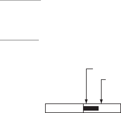
1. RADAR OPERATION
1-26
1.16 Adjusting the Sensitivity
The gain control adjusts the sensitivity of the receiver.
The proper setting is such that the background noise is just visible on the screen.
If you set up for too little sensitivity, weak echoes may be missed. On the other
hand excessive sensitivity yields too much background noise; strong targets may
be missed because of the poor contrast between desired echoes and the
background noise on the display.
To adjust receiver sensitivity, adjust the gain control so background noise is just
visible on the screen.
By keyboard
While monitoring the gain level indicator at the top of the screen, operate the
[GAIN] control to adjust the sensitivity.
By trackball
1. Use the trackball to place the arrow on the gain level indicator at the top of
the screen.
GAIN
Place arrow inside
window to adjust gain.
Level bar
30
GAIN level indicator
2. Roll the scrollwheel downward to increase the gain or upward to decrease it.
100 levels (0-100) are available.

1. RADAR OPERATION
1-27
1.17 Reducing Sea Clutter
Echoes from waves cover the central part of the display with random signals
known as sea clutter. The higher the waves, and the higher the antenna above
the water, the further the clutter extends. When sea clutter masks the picture,
reduce it by the A/C SEA control, either manually or automatically.
Note 1: When both sea clutter and rain clutter are reduced, the sensitivity is
decreased more than when only one is adjusted. For that reason adjust
them carefully.
Note 2: The echo average (see 1.27) is useful for reducing reflections from the
sea surface. However, high-speed targets are harder to detect than
stationary ones when the echo average is active.
1.17.1 Choosing method of adjustment
1. Use the trackball to select SEA AUTO or SEA MAN (whichever is shown) at
the top of the display.
SEA AUTO
Place arrow inside window
to adjust A/C SEA.
A/C SEA adjustment
method (SEA AUTO or SEA MAN)
Level bar
30
A/C SEA level indicator
2. Push the left button to display SEA AUTO or SEA MAN as appropriate.
1.17.2 Automatic reduction of sea clutter
Auto A/C SEA allows for fine tuning of the A/C SEA circuit, within ±20 dB.
Accordingly, with the bar reading set to 100, gain is not lowered to minimum as
with manual A/C SEA on close-in ranges. Further, the auto A/C SEA level is low
because the average value of the original input echo is low in areas where there
are no sea surface reflections. For example, when the ship is alongside a quay
and the radar picture shows echoes from both land and sea, you can observe
the size of the echoes because the STC curve changes with the size of the
echoes.
Note: The auto A/C function can erase weak target echoes. Adjust the control
carefully, watching the display.
By keyboard
1. Select SEA AUTO following the procedure in section 1.17.1.
2. While observing the A/C SEA level indicator, adjust the A/C SEA with the [A/C
SEA] control. 100 levels are available.

1. RADAR OPERATION
1-28
By trackball
1. Select SEA AUTO following the procedure in section 1.17.1.
2. Use the trackball to place the arrow in the A/C SEA level indicator at the top
of the display.
3. While observing the A/C SEA level indicator, roll the scrollwheel downward to
increase the A/C SEA or upward to decrease it. 100 levels (0-100) are
available.
1.17.3 Manual reduction of sea clutter
The A/C SEA control reduces the amplification of echoes at short ranges (where
clutter is the greatest) and progressively increases amplification as the range
increases, so amplification will be normal at those ranges where there is no sea
clutter.
The proper setting of the A/C SEA should be such that the clutter is broken up
into small dots, and small targets become distinguishable. If the setting is set too
low, targets will be hidden in the clutter, while if the setting is too high, both sea
clutter and targets will disappear from the display. In most cases adjust the
control until clutter has disappeared to leeward, but a little is still visible
windward. Be careful not to remove all sea clutter, because you may erase weak
echoes. Further, the possibility of losing weak echoes is greater when you use
both A/C SEA and A/C RAIN to reduce clutter.
A/C SEA adjusted;
sea clutter suppressed
Sea clutter at
screen center
By keyboard
1. Select SEA MAN following the procedure in section 1.17.1.
2. Watching the A/C SEA level indicator at the top of the display, adjust the A/C
SEA with the [A/C SEA] control. 100 levels (0-100) are available.
By trackball
1. Select SEA MAN following the procedure in section 1.17.1.
2. Use the trackball to place the arrow on the A/C SEA level indicator at the top
of the display.
3. While observing the A/C SEA level indicator, roll the scrollwheel downward to
increase the A/C SEA or upward to decrease it. 100 levels (0-100) are
available.
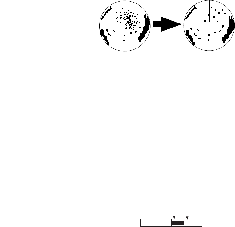
1. RADAR OPERATION
1-29
RAIN
Place arrow inside window
to adjust A/C RAIN.
Level bar
(Shows A/C RAIN level.)
30
1.18 Reducing Rain Clutter
Use the AUTO RAIN and A/C RAIN to reduced rain clutter. AUTO RAIN reduces
rain clutter in the picture and A/C RAIN reduces clutter picked up by the antenna.
Note 1: When both sea clutter and rain clutter are reduced the sensitivity is
decreased more than when only one is adjusted. For that reason adjust
them carefully.
Note 2: The echo average (see 1.27) is useful for reducing reflections from the
sea surface. However, high-speed targets are harder to detect than
stationary ones when the echo average is active.
1.18.1 Automatic reduction of rain clutter
Left-click the AUTO RAIN indication at the left side of the screen to select AUTO
RAIN setting desired. The higher the number, the greater the degree of rain
clutter reduction. OFF turns off the AUTO RAIN feature.
Note: AUTO RAIN can also be controlled from the PICTURE box.
1.18.2 Manual reduction of rain clutter
The vertical beam width of
the antenna is designed to
see surface targets even
when the ship is rolling.
However, by this design
the unit will also detect rain
clutter (rain, snow, or hail)
in the same manner as
normal targets.
The A/C RAIN control adjusts the receiver sensitivity as the A/C SEA control
does but rather in a longer time period (longer range). The higher the setting the
greater the anti-clutter effect. When echoes from precipitation mask solid targets,
adjust the A/C RAIN control to split up these unwanted echoes into a speckled
pattern, making recognition of solid targets easier. Be careful remove all rain
clutter, because you can erase weak echoes. Further, the possibility of losing
weak echoes is greater when you use both A/C RAIN and A/C SEA to reduce
clutter.
Keyboard
1. Use the trackball to put the cursor
in the A/C RAIN level indicator at
the top right side of the display.
2. While observing the A/C RAIN level
indicator, roll the scrollwheel
downward to increase the A/C RAIN
or upward to decrease it. 100 levels
(0-100) are available.
Unwanted echoes are
displayed
A/C RAIN control adjusted.
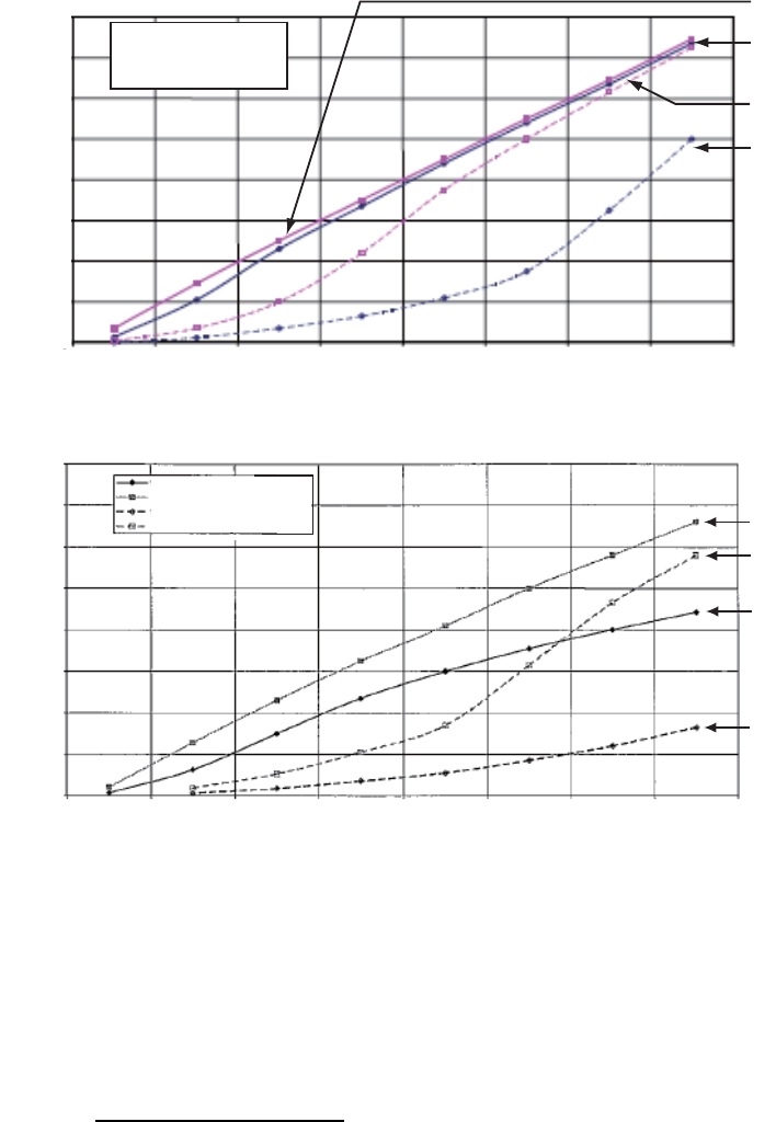
1. RADAR OPERATION
1-30
Note: The detection range is reduced when the A/C RAIN is used to show
targets in rain. Generally, the amount of rain, TX pulse length and TX
frequency are factors in determining how the detection range is affected.
The figures shown below illustrate this occurrence.
16 mm/h rain - short pulse
4 mm/h rain - short pulse
16 mm/h rain - long pulse
4 mm/h rain - long pulse
Reduction of rain to first detection due to rain at S-band
Reduction of rain to first detection due to rain at X-band
The author thanks the International Electrotechnical Commission (IEC) for permission to
reproduce Information from its International Standard IEC 62388 ed.1.0 (2007). All such extracts
are copyright of IEC, Geneva, Switzerland. All rights reserved. Further information on the IEC is
available from www.iec.ch. IEC has no responsibility for the placement and context in which the
extracts and contents are reproduced by the author, nor is IEC in any way responsible for the
other content or accuracy therein.
IEC 62388 ed.1.0 Copyright © 2007 IEC Geneva, Switzerland.www.iec.ch
Reduction of Range of First Detection (NM)
Original Range of First Detection (NM)
14
16
12
10
8
6
4
2
0
0 2 4 6 8 10 12 14 16
16
12
10
8
6
4
2
0
14
0 2 4 6 8 10 12 14 16
Original Range of First Detection (NM)
Reduction of Range of First Detection (NM)
16 mm/h rain - short pulse
4 mm/h rain - short pulse
16 mm/h rain - long pulse
4 mm/h rain - long pulse
16 mm/h rain - short pulse
4 mm/h rain - short pulse
16 mm/h rain - long pulse
4 mm/h rain - long pulse
4 mm/h rain (short pulse)
16 mm/h rain (short pulse)
16 mm/h rain (long pulse)
4 mm/h rain (short pulse)
4 mm/h rain (short pulse)
4 mm/h rain (long pulse)
16 mm/h rain (short pulse)
16 mm/h rain (long pulse)
How to read the graph
Using the X-band graph as an example, here is how to read the graphs.
A radar target detected in rain on the 8 nm range scale can only be detected at
the ranges shown below:
4 mm/h rain (short pulse): approx 7.5 nm
16 mm/h rain (short pulse): approx 5.6 nm
4 mm/h rain (long pulse): approx 2.6 nm
16 mm/h rain (long pulse): approx 0.9 nm

1. RADAR OPERATION
1-31
1.19 Measuring Range
The range to a target may be measured three ways: with the fixed range rings,
with the cursor, or with the VRM.
Use the fixed range rings to get an estimate of the range to a target. The rings
are the concentric solid circles on the display. The number of rings is
automatically set by the current range scale. The distance between the rings is
the range ring interval, and the current interval appears at the upper-left position
on the screen. To measure the range to a target with the range rings, count the
number of rings between the center of the display and the target. Check the
range ring interval and estimate the distance of the echo from the inner edge of
the nearest ring.
1.19.1 Showing, hiding the fixed range rings
1. Left-click the MENU box to open the menu.
2. Select 2 [MARK].
[MARK]
1 BACK
2 OWN SHIP MARK
OFF/MIN/SCALED
3 STERN MARK
OFF/ON
4 [PI LINE]
5 ANCHOR WATCH
OFF/ON
0.0NM
6 DROP MARK
OFF/ON
7 [INS MARK] *1
8 EBL OFFSET BASE
STAB GND/STAB HDG/
STAB NORTH
9 [EBL, VRM, CURSOR SET]*2
0 RING
OFF/ON
*
1
[BARGE MARK] depending on installation preset.
*
2
IMO and A types show
9 EBL CURSOR BEARING (REL/TRUE)
MARK menu
3. Select 0 RING.
4. Select OFF or ON as appropriate then push the left button.
5. Push the right button twice to close the menu.
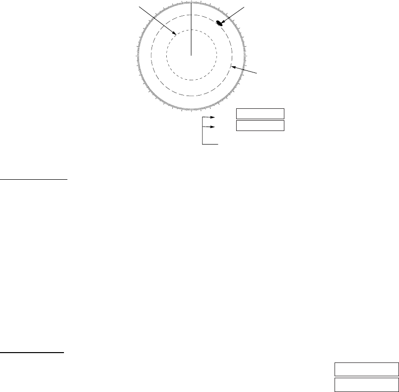
1. RADAR OPERATION
1-32
VRM1
VRM2
1.19.2 Measuring range by the variable range marker (VRM)
There are two VRMs, No. 1 and No. 2, which appear as dashed rings so that you
can distinguish them from the fixed range rings. The two VRMs can be
distinguished from each other by the different lengths of their dashes; the
dashes on the No. 2 VRM are longer.
000 010 020
030
040
050
060
070
080
090
100
110
120
130
140
150
160
170
180
190
200
210
220
230
240
250
260
270
280
290
300
310
320
330 340 350
No. 1
VRM
Target
blip
No. 2
VRM
VRM1
VRM2
>0.66NM<
1.18NM
45:02
99:59
TTG to VRM
Measuring range with VRMs
By keyboard
1. Press the [VRM ON] key to display either of the VRMs. Successively
pressing the [VRM ON] key toggles the active VRM between No. 1 and No. 2.
The currently active marker is enclosed with >...<.
2. Operate the VRM rotary control to align the active variable range marker with
the inner edge of the target of interest and read its distance at the lower-right
corner of the screen. Each VRM remains at the same geographical distance
when you operate the [RANGE] key or the RANGE box. This means that the
apparent radius of the VRM ring changes in proportion to the selected range
scale.
3. Press the [VRM OFF] key to erase each VRM.
By trackball
1. Use the trackball to place the arrow in the VRM1 or VRM2
box, whichever VRM you want to use.
2. The guidance box reads "VRM ON/." Push the left button
to turn on the VRM. The guidance box now reads "VRM SET L = DELETE /."
3. Push the left button again and the cursor jumps to inside the effective display
area. The guidance box now reads "VRM FIX / EXIT."
4. Use the trackball (coarse adjustment) or scrollwheel (fine adjustment) to
align the active variable range marker with the inner edge of the target of
interest and read its distance at the lower-right corner of the screen. Each
VRM remains at the same geographical distance when you operate the
[RANGE] key. This means that the apparent radius of the VRM ring changes
in proportion to the selected range scale.
5. Push the left button to anchor the VRM and fix its readout, or push the right
button to return the VRM to its previous location (range).
6. To erase a VRM, select the appropriate VRM readout box then push the left
button until the VRM disappears from the screen.

1. RADAR OPERATION
1-33
1.19.3 VRM unit of measurement (B and C types)
1. Left-click the MENU box to open the menu.
2. Select 2 [MARK].
3. Select 9 [EBL, VRM, CURSOR SET] then push the scrollwheel.
4. Select VRM1 or VRM2 as appropriate and push the scrollwheel.
5. Select unit of measurement desired then push the scrollwheel.
6. Push the right button twice to close the menu.
1.19.4 TTG to VRM indication
You can show the TTG to VRMs as follows:
1. Left-click the MENU box to open the menu.
2. Select 9 [CUSTOMIZE·TEST] to open the CUSTOMIZE·TEST menu.
3. Select 7 [OPERATION].
4. Select 0 NEXT.
5. Select 3 VRM TTG.
6. Select OFF, 1, 2 or 1+2 as applicable and push the left button.
OFF: NO VRM TTG display
1: TTG to VRM1
2: TTG to VRM2
1+2: TTG to VRM1 and VRM2
7. Push the right button four times to close the menu.
VRM1
>3.682NM<
00:00
TTG indication
VRM and TTG indications

1. RADAR OPERATION
1-34
1.20 Measuring Bearing
Use the Electronic Bearing Lines (EBLs) to take bearings of targets. There are
two EBLs, No. 1 and No. 2. Each EBL is a straight dashed line extending out
from the own ship position up to the circumference of the radar picture. The two
EBLs can be distinguished from each other by the different lengths of their
dashes; the dashes on the No. 2 EBL are longer.
Each EBL carries a range marker, or a short line crossing the EBL at right angles.
Its distance from the EBL origin is indicated at the VRM readout whether or not
the corresponding VRM is displayed. The range marker changes its position
along the EBL with the rotation of the VRM control. To operate this marker, rotate
the VRM rotary control on the full keyboard, or put the cursor in the applicable
VRM box and roll the scrollwheel.
1.20.1 Measuring bearing
By keyboard
1. Press the [EBL ON] key to display either of the EBLs. Successive presses of
the [EBL ON] key toggle the active EBL between No. 1 and No. 2. The
currently active marker is enclosed with >...<.
2. Operate the EBL rotary control clockwise or counterclockwise until the active
EBL bisects the target of interest, and read its bearing at the lower-left corner
of the screen.
3. Press the [EBL OFF] key to erase each EBL.
By trackball
1. Use the trackball to place the arrow in the EBL1 or EBL2 box, whichever EBL
you want to use.
EBL1
EBL2
EBL boxes
2. The guidance box reads "EBL ON/." Push the left button to turn on the EBL.
The guidance box now reads "EBL SET L=DELETE /."
3. Push the left button again and the cursor jumps to inside the effective display
area. The guidance box now reads "EBL FIX L=DELETE/."
4. Use the trackball (coarse adjustment) or scrollwheel (fine adjustment) to
bisect the target with the EBL.
5. Push the left button to anchor the EBL and fix its readout, or push the right
button to return the EBL to its previous location (bearing).
6. To erase an EBL, select the appropriate EBL readout box then push the left
button until the EBL disappears from the screen.
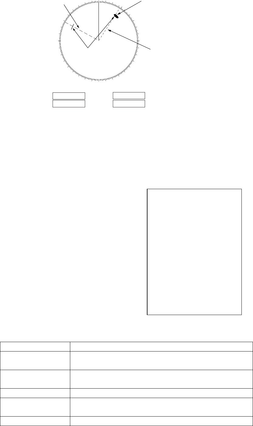
1. RADAR OPERATION
1-35
[EBL, VRM, CURSOR SET]
1 BACK
2 EBL1
REL/TRUE
3 EBL2
REL/TRUE
4 VRM1
NM/SM/km/kyd
5 VRM2
NM/SM/km/kyd
6 CURSOR BEARING
REL/TRUE
7 CURSOR RANGE
NM/SM/km/kyd
8 [◊CURSOR SHAPE]*
000 010 020
030
040
050
060
070
080
090
100
110
120
130
140
150
160
170
180
190
200
210
220
230
240
250
260
270
280
290
300
310
320
330 340 350
No. 2
EBL
Target
blip
No. 1
EBL
Range markers
on EBLs
VRM1
VRM2
12.1NM
EBL1
EBL2
>128.0
°
T<
100.8
°
T
>10.2NM<
Measuring bearing with EBLs
1.20.2 True or relative bearing
The EBL readout is affixed by "R" (relative) if it is relative to own ship's heading,
"T" (true) if it is referenced to the north. Available on the IMO and A type radars.
True or relative indication is available regardless of presentation mode.
1. Left-click the MENU box to open the
menu.
2. Select 2 [MARK] to open the MARK
menu.
3. Select 9 [EBL, VRM, CURSOR SET] (B,
C and W types) or 9 EBL CURSOR
BEARING (IMO and A types). For the B,
C and W types the menu below appears;
go to step 4. For the IMO and A types go
to step 5.
4. Select EBL1 or EBL2 as applicable.
5. Select REL or TRUE as applicable.
6. Push the right button twice to close the
menu.
Note: When the gyrocompass heading changes, the EBL and its indication
change as follows:
Head-up / relative EBL indication and EBL marker are unchanged.
Head-up / true EBL indication does not change, however the EBL
marker moves accordingly.
Course-up / relative EBL indication does not change, however the EBL
marker moves accordingly.
Course-up / true EBL indication and EBL marker are unchanged.
North-up / relative EBL indication does not change, however the EBL
marker moves accordingly.
North-up / true EBL indication and EBL marker are unchanged.

1. RADAR OPERATION
1-36
1.21 Collision Assessment by Offset EBL
The origin of the EBL can be placed anywhere with the trackball to enable
measurement of range and bearing between any targets. This function is also
useful for assessment of the potential risk of collision. It is possible to read CPA
(Closest Point of Approach) by using a VRM as shown in (a) in the illustration on
the next page. If the EBL passes through the sweep origin (own ship) as shown
in (b) in the illustration on the next page, the target ship is on a collision course.
1.21.1 How to assess risk of collision by the offset EBL
By keyboard
1. Press the [EBL ON] key to display or activate an EBL (No. 1 or No. 2).
2. Put the cursor (+) on a target appearing as threatening (A in the illustrated
example on the next page) by operating the trackball.
3. Press the [EBL OFFSET] key, and the origin of the active EBL shifts to the
cursor position. Press the [EBL OFFSET key] again to anchor the EBL origin.
4. After waiting for a few minutes (at least 3 minutes), operate the EBL rotary
control until the EBL bisects the target at the new position (A'). The EBL
readout shows the target ship's course, which may be true or relative
depending on the EBL bearing reference setting.
Note: If relative motion is selected, it is also possible to read CPA by using a
VRM as shown in left-hand figure at the top of the next page. If the
EBL passes through the sweep origin (own ship) as illustrated in the
right-hand figure at the top of then next page, the target ship is on a
collision course.
5. To return the EBL origin to the own ship's position, press the [EBL OFFSET]
key twice.
By trackball
1. Display an EBL, following steps 1-3 in "By trackball" in section 1.20.1.
2. With the cursor inside the effective display area, push the left button, roll the
scrollwheel to show "EBL OFFSET / EXIT" in the guidance box then push the
left button.
3. Use the trackball to place the offset EBL on a target appearing as threatening
(A in the illustrated example on the next page) then push the left button to
anchor the EBL origin.
4. After waiting for a few minutes (at least 3 minutes), operate the EBL used in
step 1 until it bisects the target at the new position (A'). The EBL readout
shows the target ship's course, which may be true or relative depending on
the EBL bearing reference setting.
To return the EBL origin to the screen center, show "EBL OFFSET / EXIT" in the
guidance window then push the left button.
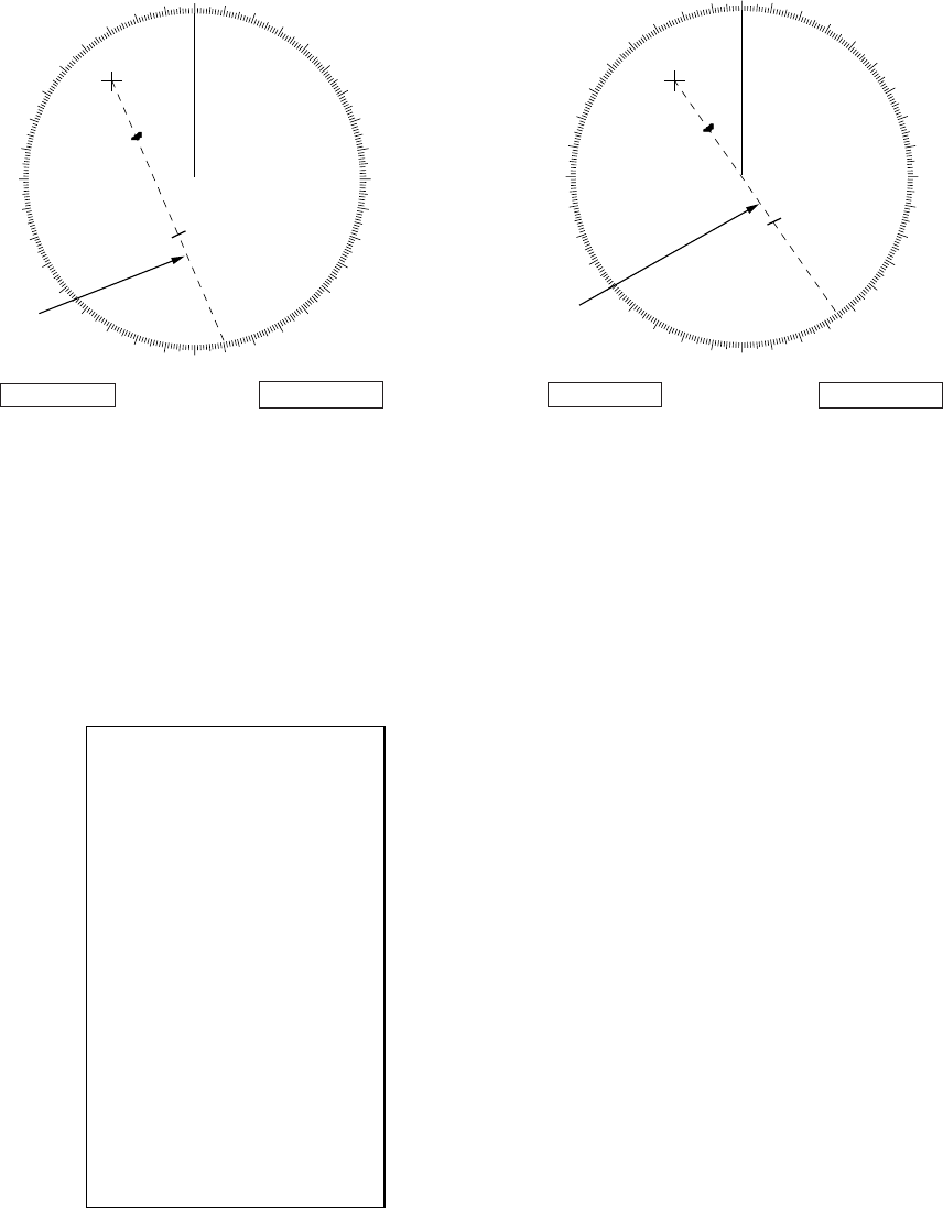
1. RADAR OPERATION
1-37
000 010 020
030
040
050
060
070
080
090
100
110
120
130
140
150
160
170
180
190
200
210
220
230
240
250
260
270
280
290
300
310
320
330 340 350
000 010 020
030
040
050
060
070
080
090
100
110
120
130
140
150
160
170
180
190
200
210
220
230
240
250
260
270
280
290
300
310
320
330 340 350
A
A
1
A
A
1
No. 1
EBL
No. 1
EBL
EBL1
>150.3
°
T<
VRM1
>3.85NM<
EBL1
>138.2
°
T<
VRM1
>3.85NM<
(a) (b)
Collision assessment by offset EBL
1.21.2 Point of reference for origin point of offset EBL
The origin point of the offset EBL can be ground stabilized (geographically fixed),
north stabilized (true) or referenced to own ship’s heading (relative).
1. Left-click the MENU box to open the menu.
2. Select 2 [MARK] to open the MARK menu.
[MARK]
1 BACK
2 OWN SHIP MARK
OFF/MIN/SCALED
3 STERN MARK
OFF/ON
4 [PI LINE]
5 ANCHOR WATCH
OFF/ON
0.0NM
6 DROP MARK
OFF/ON
7 [INS MARK] *
1
8 EBL OFFSET BASE
STAB GND/STAB HDG/
STAB NORTH
9 [EBL, VRM, CURSOR SET]*
2
0 RING
OFF/ON
*
1
[BARGE MARK] depending on installation preset.
*
2
IMO and A types show
9 EBL CURSOR BEARING (REL/TRUE)
MARK menu
3. Select 8 EBL OFFSET BASE.
4. Select STAB GND, STAB HDG or STAB NORTH as applicable.
STAB GND: Reference to latitude and longitude. Origin position is always
fixed regardless of your ship's movement.
STAB HDG: Reference to heading. The relationship between origin position
and own position is kept always.
STAB NORTH: Reference to North. The origin position changes with North
position.
5. Push the right button twice to close the menu.
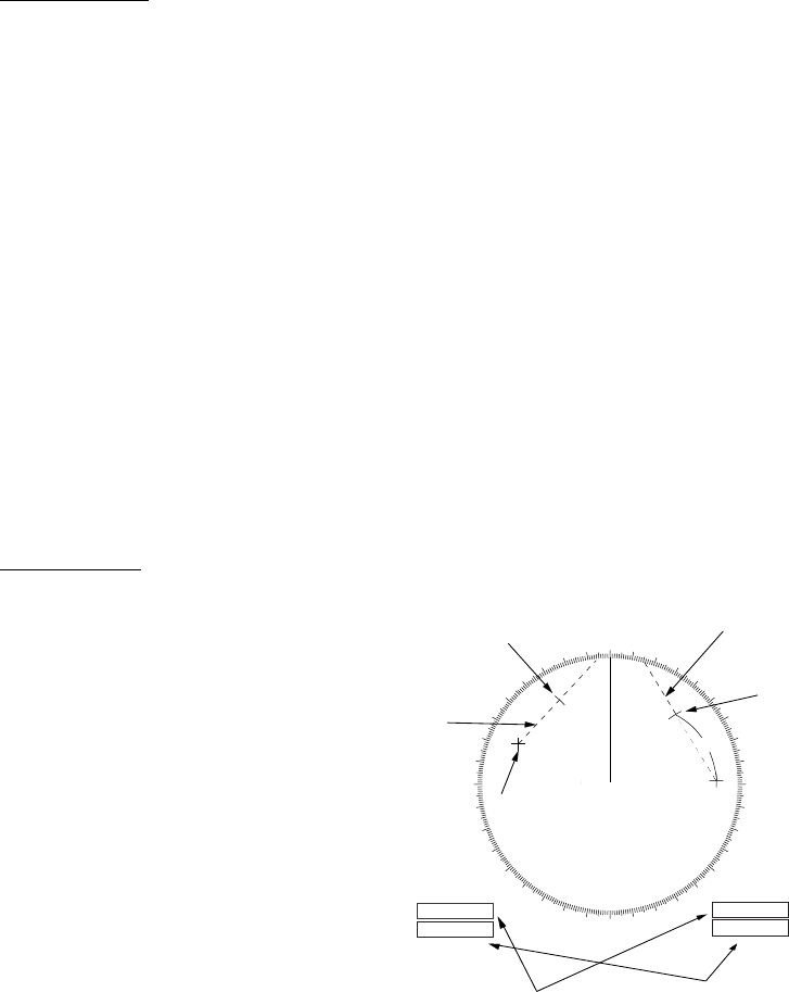
1. RADAR OPERATION
1-38
1.22 Measuring Range and Bearing Between Two
Targets
By keyboard
1. Press the [EBL OFFSET] key. Operate the trackball to place the origin of the
No. 1 EBL, for example, on a target of interest (target 1 in the illustrated
example).
2. Operate the EBL rotary control until the EBL passes through another target of
interest (target 2).
3. Operate the VRM rotary control until the range marker on the EBL is on the
inside edge of target 2. The active VRM readout at the lower-right corner of
the screen indicates the distance between the two targets.
4. You can repeat the same procedure on third and fourth targets (targets 3 and
4) by using the No. 2 EBL and the No. 2 VRM.
Bearing is shown relative to own ship with suffix "R" or as a true bearing with
suffix "T" depending on EBL relative/true settings of EBL CURSOR BEARING in
the MARK menu. To return the EBL origin to the screen center, press the [EBL
OFFSET] key again.
By trackball
1. Display an EBL, following the
steps 1-3 in section 1.20.1.
2. With the cursor inside the
effective display area, push the
left button, roll the scrollwheel
to show "EBL OFFSET / EXIT"
in the guidance box then push
the left button.
3. Use the trackball to put the
cursor on target 1 then push
the left button.
4. Operate the No. 1 VRM until
the range marker on the EBL
aligns with target 2. The active
VRM readout at the lower-right
corner of the screen indicates the distance between the two targets.
5. You can repeat the same procedure on third and fourth targets (targets 3 and
4) by using the No. 2 EBL and the No. 2 VRM.
To return the EBL origin to the screen center, show "EBL OFFSET / EXIT" in the
guidance window then push the left button.
000 010 020
030
040
050
060
070
080
090
100
110
120
130
140
150
160
170
180
190
200
210
220
230
240
250
260
270
280
290
300
310
320
330 340 350
EBL
origin
R2
Target 2
No.1
EBL
No. 2
EBL
Range
Marker
Range/bearing
between targets
1 and 2
Range/bearing
between targets 3 and 4
EBL1
EBL2
>140.0
°
R<
335.2
°
R
VRM1
VRM2
>0.50NM<
0.98NM
Range
Marker
Target 4
Target 3
Target 1
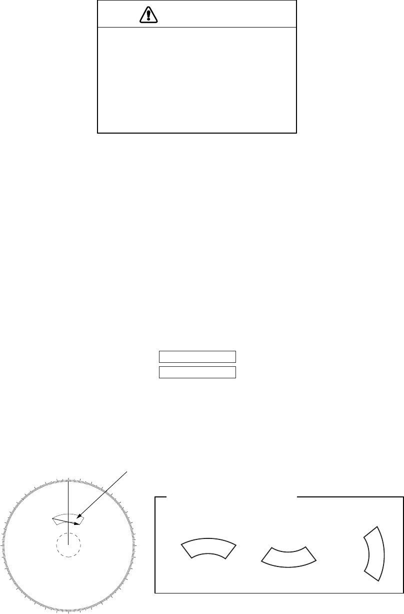
1. RADAR OPERATION
1-39
1.23 Target Alarm
The target alarm serves to alert the navigator to targets (ships, landmasses, etc.)
entering a specific area, with audiovisual alarms.
CAUTION
• The alarm should not be relied upon as
the sole means for detecting possible
collision situations.
• A/C SEA, A/C RAIN and GAIN controls
should be properly adjusted to be sure
the alarm system does not overlook
target echoes.
The target alarm zone has a fixed width of 0.5 nm in the radial direction (depth)
and is adjustable from 3.0 to 6.0 nm (guard zone 1) and any distance (guard
zone 2). On the Non-IMO radar the boundaries can be set at any distance. On
any radar type the sector of the zone can be set from 0 to 360 degrees in any
direction.
1.23.1 How to set a target alarm
The procedure below shows how to set a target alarm using the figure below as
an example.
1. Left-click ALARM1 or ALARM2 box, whichever alarm you wish to put the
cursor jumps into the effective display area and "SET" appears inside the
ALARM box selected.
ALARM 1
ALARM 2
ALARM boxes
2. Use the trackball to put the cursor on point "A" then push the left button.
3. Use the trackball to put the cursor on point "B" then push the left button.
"WORK" replaces "SET" in the ALARM box. The target alarm zone’s lines are
shown in dashed lines.
000 010 020
030
040
050
060
070
080
090
100
110
120
130
140
150
160
170
180
190
200
210
220
230
240
250
260
270
280
290
300
310
320
330 340 350
Target alarm zone
AB
X
X
Point A
X
X
X
X
Point B
Point B
Point B
Point A
Point A
Other alarm zone examples
Target alarm zone
1. RADAR OPERATION
1-40
Note 1: If you wish to create a target alarm zone having a 360-degree coverage
around own ship, set point "B" in almost the same direction as point "A."
Note 2: Two target alarm zones may be set. Note however that the 2nd target
alarm zone is available only when the 1st target alarm zone is active.
Note 3: When the target alarm zone is not within the range in use the indication
UP RNG appears to the right of the ALARM box. In this case select a
range that will display the target alarm zone.
1.23.2 Acknowledging the target alarm
A target in the target alarm zone produces both visual (flashing) and audible
(beep) alarms. To silence the audio alarm, press the [ALARM ACK] key on the
full keyboard or select the appropriate ALARM box then push the left button. The
ALARM box shows "ALARMx ACK." This will deactivate the audio alarm but will
not stop the flashing of the offending target. To reactivate the audio alarm, press
the [ALARM ACK] key again or select the ALARM box then push the left button.
(When an external buzzer is connected, the audio alarm does not stop until the
alarm zone itself is deactivated.) The ALARM box shows "ALARMx WORK."
1.23.3 Deactivating a target alarm
Left-click ALARM1 or ALARM2 box, whichever alarm you wish to deactivate,
until the alarm status in the ALARM box disappears. In this radar deactivation of
the target alarm zone 1 deactivates target alarm zone 2
.

1. RADAR OPERATION
1-41
[ALARM]
1 BACK
2 TARGET ALARM MODE
IN/OUT
3 TARGET ALARM LEVEL
1/2/3/4
4 WATCH ALARM
OFF/6M/10M/
12M/15M/20M
5 ALARM SOUND LEVEL
OFF/LOW/MID/HIGH
6 [ALARM OUT1]
7 [ALARM OUT2]
8 [ALARM OUT3]
9 [ALARM OUT4]
0 [PRIMARY ALARM]
1.23.4 Target alarm attributes
You may select the echo strength level that triggers the alarm, the condition that
generates the alarm and the volume of the audio alarm as follows:
1. Left-click the MENU box to open the menu.
2. Select 3 [ALARM].
ALARM menu
3. Select 2 TARGET ALARM MODE.
4. Select IN or OUT as appropriate.
IN: Targets entering the zone trigger the alarms.
OUT: Targets exiting the zone trigger the alarms.
Inward target alarm Outward target alarm
Alarm types
5. Select 3 TARGET ALARM LEVEL.
6. Select echo strength level that will trigger the alarm. "1" is highest strength.
7. Select 5 ALARM SOUND LEVEL.
8. Select audio alarm volume, among OFF, LOW, MID and HIGH.
Note: 5 ALARM SOUND LEVEL also sets the level of the audio alarm for the
watch alarm.
9. Push the right button twice to close the menu.
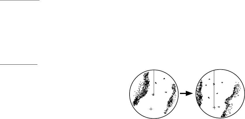
1. RADAR OPERATION
1-42
Cursor
Put cursor where desired
and do appropriate
OFF CENTER
p
rocedure
Off-centered display
1.24 Off-Centering the Display
Own ship position, or sweep origin, can be displaced to expand the view field
without switching to a larger range scale. The sweep origin can be off-centered
to the cursor position, but not more than 75% of the range in use; if the cursor is
set beyond 75% of the range scale, the sweep origin will be off-centered to the
point of 75% of the limit.
This feature is not available on the 96 nm range or in the true motion mode.
If the conning position is outside the effective radar display, some parts of the
bearing scale are not shown. For details, see section 1.50.
To off-center the radar picture, do the following:
By keyboard
1. Use the trackball to put the cursor at a position where you wish to move the
sweep origin.
2. Press the [OFF CENTER] key. Then, the sweep origin is off-centered to the
cursor position.
3. To cancel off-centering, press the [OFF CENTER] key again.
By trackball
1. With the cursor inside the effective
display area, roll the scrollwheel to
display "OFF CENTER / EXIT" in
the guidance box.
2. Use the trackball to put the cursor
where you want to locate the screen
center.
3. Push the left button to off center the
sweep origin.
4. To cancel the off-center function, push the left button when the guidance box
reads "OFF CENTER / EXIT."
Note: When the conditions shown below are met, offcenter cannot be cancelled.
This is because the radar antenna position is located at a position greater than
75% of the effective radar display.
- Own ship marker is large
- The distance between antenna position and conning position is large
- Short-distance display range.
To cancel the offcenter first select a larger range then cancel the offcenter.
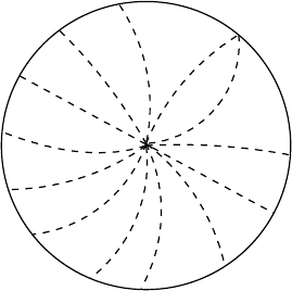
1. RADAR OPERATION
1-43
1.25 Interference Rejector
Mutual radar interference may occur in the vicinity of another shipborne radar
operating in the same frequency band. It is seen on the screen as a number of
bright spikes either in irregular patterns or in the form of usually curved
spoke-like dotted lines extending from the center to the edge of the picture.
Activating the interference rejector circuit can reduce this type of interference.
The interference rejector is a kind of signal correlation circuit. It compares the
received signals over successive transmissions and reduces randomly occurring
signals. There are three levels of interference rejection depending on the
number of transmissions that are correlated.
Interference
To adjust the interference rejector, left-click IR indication at the left side of the
screen to select rejection level. "3" provides the highest degree of reduction.
Note: The interference rejector can also be adjusted from the PICTURE box.
1.26 Echo Stretch
The echo stretch feature enlarges targets in the range and bearing directions to
make them easier to see, and it is available on any range. There are three types
of echo stretch, 1, 2 and 3, and the higher the number the greater the amount of
stretch.
Note: The echo stretch magnifies not only small target pips but also returns
(clutter) from sea surface, rain and radar interference. For this reason,
make sure these types of interference have been sufficiently reduced
before activating the echo stretch.
To set echo stretch, left-click the ES indication at the left side of the display.
Note: Echo stretch can also be adjusted from the PICTURE box.
1. RADAR OPERATION
1-44
1.27 Echo Averaging
The echo averaging feature effectively reduces sea clutter. Echoes received
from stable targets such as ships appear on the screen at almost the same
position every rotation of the antenna. On the other hand, unstable echoes such
as sea clutter appear at random positions.
To distinguish real target echoes from sea clutter, echoes are averaged over
successive picture frames. If an echo is solid and stable over successive frames,
it is presented in its normal intensity. Sea clutter is averaged over successive
scans and its brilliance reduced, making it easier to discriminate real targets
from sea clutter.
Echo averaging uses scan-to-scan signal correlation technique based on the
true motion over the ground of each target. Thus, small stationary targets such
as buoys will be shown while reducing random echoes such as sea clutter. True
echo averaging is not however effective for picking up small targets running at
high speeds over the ground.
Note 1: With echo average active it is harder to detect high-speed targets than
stationary ones.
Note 2: Do not use the echo averaging function under heavy pitching and
rolling; loss of targets can result.
Note 3: Echo averaging can be used without a heading sensor. For further
details, contact your dealer.
Note 4: Echo averaging requires heading, position and speed data.
Before using the echo averaging function, reduce sea clutter with the A/C SEA
control. Leave a little sea clutter on the screen so as not to erase weak targets.
Then, do as follows:
Left-click the EAV indication at the left side of the display.
OFF: Echo averaging OFF
1, 2: Detects targets hidden in sea clutter. "2" is more effective than "1" in
detecting targets hidden in strong sea clutter. However, "1" is more
effective than "2" in displaying high-speed targets. Select the setting
best suited to current conditions. For effective monitoring of
high-speed craft, you should use "2" together with Wiper.
3: Stably displays unstable targets; distinguishes high-speed craft from
sea clutter.
Note: Echo averaging can also be adjusted from the PICTURE box.

1. RADAR OPERATION
1-45
[PICTURE MENU]
1 INT REJECT
OFF/1/2/3
2 ECHO STRETCH
OFF/1/2/3
3 ECHO AVERAGE
OFF/1/2/3
4 NOISE REJ
OFF/ON
5 AUTO STC
OFF/ON
6 AUTO RAIN
OFF/1/2/3/4
7 VIDEO CONTRAST
1/2/3/4/
A/B/C
8 [PULSE]
9 [CONDITION]
0 DEFAULT
NO/SAVE/USER/
FACTORY
1.28 Noise Rejector
White noise may show itself on the screen as random "speckles" spread over
the entire radar image. You can remove this noise as follows:
1. Right-click the PICTURE box at the left side of the screen to open the
PICTURE menu.
2. Select 4 NOISE REJ.
3. Select ON or OFF as appropriate.
4. Push the right button to close the menu.

1. RADAR OPERATION
1-46
1.29 Wiper
The wiper feature automatically reduces the brilliance of weak signals (noise,
sea clutter, rain clutter, etc.) and unwanted signals such as radar interference to
clear the picture of unwanted echoes. Its effect depends on the wiper setting
used and whether each averaging is turned on or off, as described below.
Echo averaging and wiper states and wiper effect
Wiper setting 1 Wiper setting 2
Echo averaging OFF Condition A Condition A
Echo averaging ON (1/2/3) Condition A Condition B
Condition A: The brilliance of unwanted weak echoes, such as noise, sea
clutter and rain clutter, is reduced to clear up the picture. The difference between
wiper setting "1" and "2" is that brilliance is lowered more slowly in "2".
Condition B: Echo averaging is automatically activated when the wiper feature
is turned on, allowing you to instantly see how the picture is affected with echo
averaging turned off and turned on.
To activate the wiper feature, do the following:
1. Left-click the MENU box to open the menu.
2. Select 1 [ECHO] to open the ECHO menu.
[ECHO]
1 BACK
2 2ND ECHO REJ
OFF/ON
3 TUNE INITIALIZE
4 PM
OFF/ON
5 SART
OFF/ON
6 WIPER
OFF/1/2
7 ECHO AREA*
1
CIRCLE/WIDE/ALL
*
1
Not available on IMO or A type
8 [PICTURE SELECT]
9 STC RANGE
+00
ECHO menu
3. Select 6 WIPER.
4. Select OFF, 1 or 2 as appropriate.
5. Push the right button twice to close the menu.

1. RADAR OPERATION
1-47
1.30 Target Trails
The trails of the radar echoes of targets may be
displayed in the form of synthetic afterglow.
Target trails are shown either relative or true
and may be sea or ground stabilized. True
motion trails require a compass signal, and
position and speed data.
1.30.1 True or relative trails
You may display echo trails in true or relative
motion. Relative trails show relative movements
between targets and own ship. True motion
trails present true target movements in
accordance with their over-the-ground speeds
and courses.
Note: When true trail is selected on the RM
mode, the TRAIL MODE box is shown in
blue. The reference for the past position
displays for AIS and TT is also switched
whenever trail reference is switched.
1. Right-click the TRAIL MODE box at the bottom right corner of the screen to
open the TRAIL menu.
*
1
Shown when 8 TRAIL LENGTH
is selected to other than "NORMAL".
Other than IMO and A types.
W-type does not show 48H.
*
2
B and C types only
[TRAIL MENU]
1 TRAIL MODE
REL/TRUE
2 TRAIL GRAD
SINGLE/MULTI
3 NARROW TRAIL*
3
OFF/1/2
4 TRAIL LEVEL
1/2/3/4
5 TRAIL RESTART
OFF/ON
6 TRAIL COPY
OFF/ON
7 OS TRAIL
OFF/1/2
8 TRAIL LENGTH*
1
NORMAL/12H/24H/48H
9 TRAIL HIDE*
1
START 00:00
END 00:00
0 [TRAIL COLOR]*
1
,*
2
*
3
B, C and W types
2. Select 1 TRAIL MODE.
3. Select TRUE or REL.
4. Push the right button to close the menu.
(a) True target trails
(No smearing of
stationary targets)
(b) Relative target trails
(Targets moving relative
to own ship)
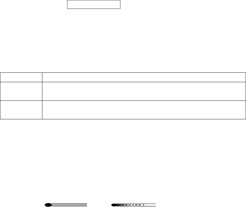
1. RADAR OPERATION
1-48
1.30.2 Trail time
Trail time, the trail plotting interval, may be selected as follows:
1. Select the arrow in the TRAIL MODE box at the bottom right corner of the
screen.
* TRAIL **
* TRUE-S(or -G) or REL
S: Sea stablized
G: Ground stabilized
** Trail time setting
TRAIL MODE box
2. Push the left button to select the trail time as below.
Control Available setting
Left button OFF, 15 sec, 30 sec, 1 min, 3 min, 6 min, 15 min, 30 min,
CONT(inuous)
Scrollwheel OFF, 15 sec, 30 sec, 1-30 min (30 sec intervals),
CONT(inuous)
The timer above the TRAIL MODE box counts up the trail time and is erased
once the terminal count is reached. For example, if the trail time is six minutes,
the timer is erased when trails have been plotted six minutes. The maximum
time for continuous plotting is 99:59.
1.30.3 Trail gradation
The afterglow can be selected in a single tone or gradual shading.
Monotone
(Single)
Gradual shading
(Multi)
Trail gradation
1. Right-click the TRAIL MODE box to display the TRAIL menu.
2. Select 2 TRAIL GRAD.
3. Select SINGLE (single) or MULTI (multiple) as appropriate.
4. Push the right button to close the menu.
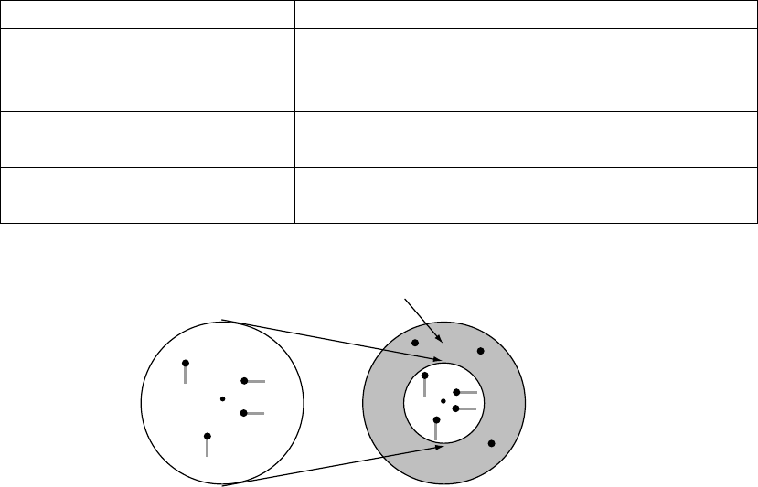
1. RADAR OPERATION
1-49
1.30.4 Saving, copying target trails
By turning on the functions TRAIL RESTART and TRAIL COPY, you may
continue painting target trails whenever the range scale is changed. The amount
of range change determines how the radar paints trails. See the table below for
details. Note however that if the previous range is restored within 10 seconds
and the amount of range change is within 1/3, trails continue as before.
If trails become difficult to view, you may delete them. For details, see section
1.30.10.
Amount of range change How trails are processed
Large (ex. 3 nm→12 nm) Trails continue on targets that were within the
previous range scale. Trails are not initiated for
targets that were not within the previous range.
Within 1/3 of previous range
(ex. 3 nm→1.5 nm)
Trails continue on targets that were in the
previous range scale.
Within 1/4 of previous range
(ex. 3 nm→0.75 nm)
Trails are restarted.
(a) Previous range (b) New range
No trail generated
for target not within
previous range
1. Right-click the TRAIL MODE box to display the TRAIL menu.
2. Select 5 TRAIL RESTART.
3. Select ON or OFF as appropriate.
ON: Trails start extending on the newly selected range.
OFF: Trails extend only on the range where they were initiated.
4. Select 6 TRAIL COPY.
5. Select ON or OFF as appropriate.
6. Push the right button to close the menu.

1. RADAR OPERATION
1-50
The relationship between trail restart and trail copy depends on their status, as
shown in the table below.
Trail restart Trail copy Trail status
ON ON Range changed while trail is ON: Trails continue on
targets within previous range.
ON OFF Range changed while trail is ON: Trails within the
previous range are erased then trails are restarted.
OFF OFF/ON
• Range changed while trail is ON: New trails not
initiated. (Trails from previous range are stored in
memory.)
• Range returned to previous range: Trails continues
on targets stored in memory.
• Trails turned ON: Trails stored in memory are
erased. (See section 1.30.10.)
(Trails stored in the memory are erased and trails are
then initiated on new range.)
1.30.5 Trail level
The level (intensity) of the afterglow that extends from radar targets may be
selected as below.
1. Right-click the TRAIL MODE box to display the TRAIL menu.
2. Select 4 TRAIL LEVEL.
3. Select level desired. The higher the number the greater the intensity of the
afterglow.
4. Push the right button to close the menu.
1.30.6 Narrow trails (B, C and W types)
Target trails may be painted with thinner lines if desired. This can be useful when
there are a lot of targets on the screen and it is hard to distinguish one from
another.
1. Right-click the TRAIL MODE box to display the TRAIL menu.
2. Select 3 NARROW TRAIL.
3. Select OFF, 1 or 2 as appropriate. "2" is thinner than "1".
4. Push the right button to close the menu.
1. RADAR OPERATION
1-51
1.30.7 Longer trails (B, C and W types)
In addition to the trail times mentioned in section 1.30.2, you may also extend
trails 12 ,24 or 48 hours.
1. Right-click the TRAIL MODE box to display the TRAIL menu.
2. Select 8 TRAIL LENGTH.
3. Select NORMAL, 12H, 24H or 48H as appropriate.
Note: 48H not available with W-type.
NORMAL: Trails are extended according to the setting made on the TRAIL
MODE box.
12H: Extend trails for 12 hours.
24H: Extend trails for 24 hours.
48H: Extend trails for 48 hours (not available on W type).
4. If you selected 12 hour, 24 hour or 48 hour, 9 TRAIL HIDE appears together
with start and end times. This item allows you to designate a time period in
which no trails will be extended. Enter time frame at START and END.
5. Push the right button to close the menu.
1.30.8 Temporarily removing trails from the display
You may wish to temporarily remove all trails from the display. Trails are
removed but are continued internally.
By keyboard: Press the [CANCEL TRAILS] key to show OFF in the TRAIL
MODE box.
By trackball: Left-click the TRAIL MODE box to display OFF in the box.
1.30.9 Trail stabilization in true motion
True motion trails may be ground stabilized or sea stabilized. The TRAIL box
shows current stabilization as TRUE-G or TRUE-S. To change stabilization mode,
open the SPEED menu and set SHIP SPEED to BT (ground stabilization) or WT
(sea stabilization).
1.30.10 Erasing trails
All trails may be erased (including those in the memory) and restarted to start
trails fresh.
By keyboard: Press and hold down the [CANCEL TRAILS] key until trails
disappear.
By trackball: Left-click the TRAIL MODE box until all trails disappear.
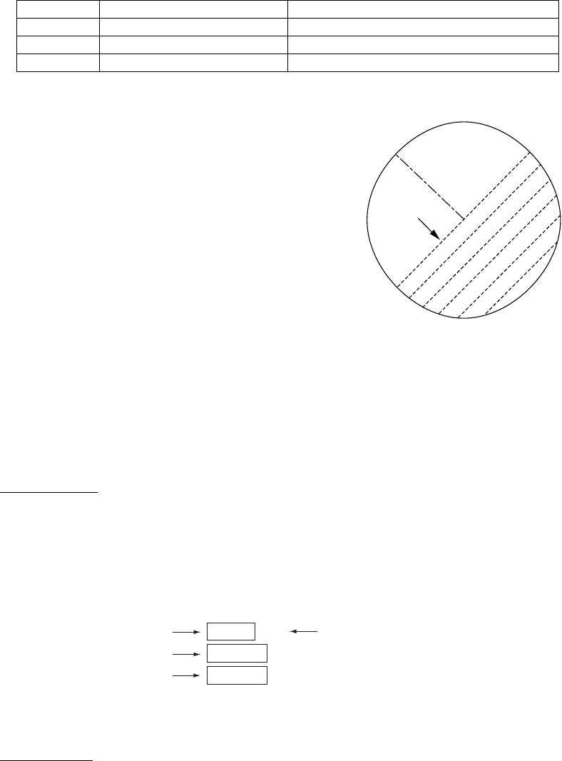
1. RADAR OPERATION
1-52
PI
lines
1.30.11 Preventing sea clutter in true trails
You can prevent the display of sea clutter in true trails about your ship to clear
the radar picture. Your ship's trails can also be shown or hidden.
1. Right-click the TRAIL MODE box to show the TRAIL menu.
2. Select 7 OS TRAIL and push the left button.
3. Roll the scrollwheel to select OFF, 1 or 2 as appropriate, referring to the table
below.
Option Show own ship's trail Prevent sea clutter in true trails
OFF No No
1 Yes Yes
2 No Yes
4. Push the right button to close the menu.
1.31 PI (Parallel Index) Lines
PI lines are useful for keeping a constant
distance between own ship and a coastline or
a partner ship when navigating. Up to six sets
of PI lines are available depending on the
maximum number of PI lines selected on the
menu.
Max. 1 PI line: Six sets of PI lines (PI1 - PI6)
Max. 2, 3 or 6 PI lines: Four sets of PI lines
(PI1 – PI4)
You may control the orientation and interval of the PI lines from the PI line box,
which is at the lower left corner.
1.31.1 Displaying, erasing PI lines
By keyboard
1. With the menu closed, press the [INDEX LINE] key. The guidance box shows
"DISP PI LINE/."
2. While watching the PI line number box, press and hold the [INDEX LINE] key
to select a PI line. Press the key again to display or erase the PI line
selected.
PI line number Status (ON or OFF)
PI 1
ON
032.0°T
5.60NM
PI line orientation
PI line interval
(Boxes not shown when
PI line is OFF.)
PI line boxes
By trackball
1. Select the PI line number box and use the trackball to select a PI line
number.
2. Push the left button to turn the PI line on or off as appropriate.

1. RADAR OPERATION
1-53
PI 1
ON
032.0°T
5.60NM
PI line orientation
PI line interval
[PI LINE]
1 BACK
2 PI LINE BEARING
REL/TRUE
3 PI LINE
1/2/3/6
4 PI LINE MODE
PARALLEL/PERPENDIC.
5 RESET PI LINE
NO/YES
1.31.2 Adjusting PI line orientation, PI line interval
1. If not already displayed, show a PI line, referring to section 1.31.1.
2. Use the trackball to place the arrow in
the PI line orientation box.
3. Roll the scrollwheel to adjust the PI
line orientation, between
000.0-359.9(°T). Enter a negative
value to move the PI line to the opposite side of the PI line passing through
the own ship position.
4. Use the trackball to put the cursor in the PI line interval box.
5. Roll the scrollwheel to adjust the PI line interval.
1.31.3 PI line bearing reference
PI line bearing reference may be relative to own ship’s heading (Relative) or
referenced to North (True) as below.
1. Left-click the MENU box to open the menu.
2. Select 2 [MARK].
3. Select 4 [PI LINE].
4. Select 2 PI LINE BEARING.
5. Select REL or TRUE as appropriate.
6. Push the right button twice to close the menu.

1. RADAR OPERATION
1-54
1.31.4 Maximum number of PI lines to display
The maximum number of PI lines to display may be selected from 1, 2, 3 or 6
lines as below. The actual number of lines visible may be less depending on line
interval. For the W specification radar, you may specify the number of lines for
two sets of PI lines – the menu displays 4 PI LINE1 and 5 PI LINE2.
1. Left-click the MENU box to open the menu.
2. Select 2 [MARK] to open the MARK menu.
3. Select 4 [PI LINE].
4. Select 3 PI LINE.
5. Select 1, 2, 3 or 6 as appropriate.
6. Push the right button twice to close the menu.
1.31.5 PI line orientation
PI lines orientation may be selected from parallel or perpendicular. This function
is available when 3 PI LINE in the PI LINE menu is set for other than "1".
1. Left-click the MENU box to open the menu.
2. Select 2 [MARK] to open the MARK menu.
3. Select 4 [PI LINE].
4. Select 4 PI LINE MODE.
5. Select PARALLEL or PERPENDIC. as appropriate.
6. Push the right button twice to close the menu.
1.31.6 Resetting PI lines
You can automatically return PI lines to default orientation, 0-degrees for parallel
orientation, 90-degrees for perpendicular orientation. This is faster than doing it
manually.
From the menu
1. Left-click the MENU box to open the menu.
2. Select 2 [MARK] to open the MARK menu.
3. Select 4 [PI LINE].
4. Select 5 PI LINE MODE.
5. Select YES.
6. Push the right button twice to close the menu.
From the PI line number box
Put the cursor on the PI line number box and long-push the left button.

1. RADAR OPERATION
1-55
1.32 Origin Mark
You can mark any prominent target or a point of particular interest using the
origin mark feature. Twenty origin marks may be entered: 10 standard origin
marks (with number) and one each of the 10 symbol origin marks. The marks
may be geographically fixed (ground stabilized) or sea stabilized. To display the
origin marks, heading signal and own ship position data are required.
1.32.1 Entering origin marks
1. Use the trackball to select the MARK box at the left side of the screen. The
guidance box now reads "MARK SELECT / MARK MENU."
MARK
Mark type last selected,
mark number -> +
1
MARK box
2. Push the right button to open the MARK menu.
[MARK MENU]
1 ORIGIN MARK STAB
GND/SEA
2 MARK KIND
ORIGIN MARK(No. )/
ORIGIN MARK(SYM)/
MAP MARK/
WP 1~50/
WP 51~ 100/
WP 101~150/
WP 151~198/
OWN SHIP SHAPE
8 MARK POSN
CURSOR/OS/L/L
00°000.00 N
000°000.00 E
9 MAP DISPLAY
OFF/ON
0 MAP MARK COLOR*
RED/GRN/BLU/YEL/
CYA/MAG/WHT
* Not available on IMO
or A type
MARK menu
3. Select 2 MARK KIND.
4. Select ORIGIN MARK (No.) or ORIGIN MARK (SYM) as appropriate. Select
ORIGIN MARK (No.) to inscribe standard origin mark ( ) plus mark number;
ORIGIN MARK (SYM) to inscribe desired origin mark symbol (no number).
5. Push the left button.
6. Push the right button to close the menu. The guidance box now reads
"MARK SELECT / MARK MENU."
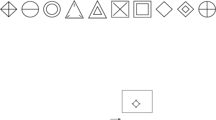
1. RADAR OPERATION
1-56
7. With the cursor choosing the MARK box, Select mark number desired
("ORIGIN MARK(No.)" selected at step 4) or origin mark symbol ("ORIGIN
MARK(SYM)" selected at step 4) then push the left button. The following
origin marks are available.
Origin mark (symbols)
8. Push the left button again. The cursor jumps into the effective display area
and the guidance box now reads "MARK / EXIT."
9. Use the trackball to put the cursor on the location desired.
10. Push the left button to inscribe the origin mark at the cursor location. The
bearing and range from the origin mark to the cursor location are shown just
below the MARK box.
MARK
-> +
162.5°T 11.7
NM
Bearing and range from
origin mark to cursor
1
Mark box, showing bearing and range from origin mark
• To inscribe a different standard origin mark number or symbol origin mark,
repeat steps 7-10. (ORIGIN MARK(No.) or (ORIGIN MARK(SYM) should be
preselected as appropriate.)
• To quit entering origin marks, push the right button when the guidance box
reads "MARK / EXIT."
• Origin mark data reads "- - -.-" when the cursor is placed outside the effective
display area.
• "ORIGIN" appear to the right of the MARK box when an origin mark item is
selected.

1. RADAR OPERATION
1-57
1.32.2 Origin mark stabilization
Origin marks may be geographically fixed (ground stabilized) or moving (sea
stabilized).
1. Right-click the MARK box to open the MARK menu.
[MARK MENU]
1 ORIGIN MARK STAB
GND/SEA
2 MARK KIND
ORIGIN MARK(No. )/
ORIGIN MARK(SYM)/
MAP MARK/
WP 1~50/
WP 51~ 100/
WP 101~150/
WP 151~198/
OWN SHIP SHAPE
8 MARK POSN
CURSOR/OS/L/L
00°000.00 N
000°000.00 E
9 MAP DISPLAY
OFF/ON
0 MAP MARK COLOR*
RED/GRN/BLU/YEL/
CYA/MAG/WHT
* Not available on IMO
or A type
MARK menu
2. Select 1 ORIGIN MARK STAB then push the scrollwheel.
3. Select GND or SEA as appropriate.
4. Push the right button to close the menu.
1.32.3 Deleting individual origin marks
The procedure below shows how to delete individual origin marks. Note that
origin marks cannot be deleted collectively.
1. With the cursor inside the effective display area, roll the scrollwheel to
display "MARK DELETE / EXIT" in the guidance box.
2. Use the trackball to put the cursor on the origin mark you wish to erase.
3. Push the left button or the scrollwheel to erase the mark.
4. To erase another mark, repeat steps 2 and 3.
5. To finish, push the right button when the guidance box reads "MARK
DELETE / EXIT."
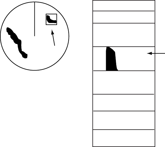
1. RADAR OPERATION
1-58
1.33 Zoom
The zoom function enlarges an area of interest as large as twice the normal
viewing size, in the text window. To use the zoom display, it must be turned on in
the DATA BOX menu. For further details, see section 1.42.
Zoom is not available when the tracked target data setting is "LARGE".
1. With the cursor inside the effective display area, roll the scrollwheel to display
"ZOOM / EXIT" in the guidance box.
2. Use the trackball to select the location to zoom.
3. Push the left button or the scrollwheel. A rectangle inscribes the location
zoomed and the zoom display at the right side of the screen shows the
zoomed picture.
Zoom area selected
with the cursor
Data Box
Zoom
Area
Zoom display
(Appears in box above
when nav data is turned
off.)
Zoom display
To quit the zoom display, push the left button when the guidance box reads
"ZOOM / EXIT."

1. RADAR OPERATION
1-59
1.34 Markers
1.34.1 Heading line
The heading line is a line from the own ship position to the outer edge of the
radar display area and appears at zero degrees on the bearing scale in head-up
mode; it changes the orientation depending on the ship orientation in north-up
and true motion modes.
Temporarily erasing the heading line
To temporarily extinguish the heading line to look at targets existing dead
ahead of own ship, press the [HL OFF] key on the keyboard, or use the
trackball to select the HL OFF box at the bottom left corner of the display then
push the left button. In addition to the heading line, the stern marker and all
graphics within the effective display are also erased. To redisplay the heading
line, etc., release the key or the left button.
1.34.2 Stern marker
The stern marker, which is a dot-and-dash line, appears opposite to the heading
line. To display or erase this marker do the following:
1. Left-click the MENU box to open the MAIN menu.
2. Select MARK to show the MARK menu.
3. Select 3 STERN MARK.
4. Select OFF or ON as appropriate.
5. Push the right button twice to close the menu.
1.34.3 North marker
The north marker appears as a short dashed line. In the head-up mode, the
north marker moves around the bearing scale in accordance with the compass
signal.
1. RADAR OPERATION
1-60
1.34.4 Own ship symbol
The own ship symbol marks own position on the display. It can be turned on or
off and its configuration selected from the MARK menu. Two configurations are
available: minimized symbol and scaled symbol. The scaled symbol is scaled to
indicate the length and beam of the vessel. If the largest dimension of the
symbol gets smaller than 6 mm, the symbol will disappear and own ship will be
with a minimized symbol. Ship’s dimensions should be entered at installation to
use the scaled ship symbol.
Scaled symbol Minimized symbol
Heading line
Beam line
X
Antenna
position
Heading line
Beam line
1. Left-click the MENU box to open the menu.
2. Select 2 to show the MARK MENU.
3. Select OFF, MIN or SCALED as appropriate.
4. Push the right button twice to close the menu.

1. RADAR OPERATION
1-61
[BARGE INFORMATION]
1 BACK
2 BARGE MARK
OFF/ON
3 BARGE SIZE
LENGTH 0ft
WIDTH 0ft
4 ARRANGEMENT
4
9
9
9
4
1.34.5 Barge marker
You may mark the locations of barges on the display with icons. This feature is
available with an installation preset. Set up barge information as follows:
1. Left-click the MENU box to open the menu.
2. Select 2 [MARK] to show the MARK menu.
3. Select 7 [BARGE MARK].
BARGE INFORMATION menu
4. Select 2 [BARGE MARK] and push the left button. Select ON and push the
left button.
5. Select 3 BARGE SIZE and push the left button. Enter length (three digits)
and width (two digits) of barge.
6. Select 4 ARRANGEMENT and push the left button. This item lets you set a
single barge or a barge chain. Select one of the five arrangements and push
the scrollwheel. Select number of barges (max. 9) to display. As you roll the
scrollwheel the squares light or extinguish and the number of barges
selected appears at the right side.
7. Push the right button twice to close the menu.
X
Barge
Far left is 1st row
1.34.6 INS marker
You can get predicted position data by connecting this radar to an INS.
1. Open the menu and select 2 [MARK].
2. Spin the scrollwheel to select 7 [INS MARK] and 7 PREDICTOR.
3. Select ON.
4. Push the right button three times to close the menu.

1. RADAR OPERATION
1-62
1.35 Automatic Picture Setup According to
Navigation Purpose
Every time your navigating environment or task changes, you must adjust the
radar, which can be a nuisance in a busy situation. Instead of changing radar
settings case by case, it is possible to assign the function keys to provide
optimum settings for often encountered situations.
The radar's internal computer offers several picture setup options to be assigned
to each function key for your specific navigating requirements. For instance, one
of the functions is assigned the ship detecting function and labeled SHIP on the
on the PICTURE box. By choosing SHIP, the radar will be instantly set for
optimum detection of ships.
Four user-programmable setups are also provided (labeled
PICTURE1-PICTURE4), so that you may have the radar automatically adjusted
to those conditions that are not covered by the provided setup options.
Below are the preset picture setup options provided with this radar.
Picture setup options description
Label Description Label Description
NEAR Optimum setting for short range
detection using a range scale of 3
nm or less on calm seas
FAR Optimum setting for long range
detection using a range scale of 6
nm or larger
NEAR
BUOY
Optimum setting for detecting
navigation buoys, small vessels
and other small surface objects at
close range
FAR
BUOY
Optimum setting for detecting
navigation buoys, small vessels
and other small surface objects at
long range
HARBOR Optimum setting for short range
navigation in a harbor area, using
a range scale of 1.5 nm or less
COAST For coastal navigation using a
range scale of 12 nm or less
ROUGH
SEA
Optimum setting for rough weather
or heavy rain
SHIP Optimum setting for detecting
vessels
Each picture setup option defines a combination of several radar settings for
achieving optimum setup for a particular navigating situation. Those involved are
interference rejector, echo stretch, echo average, noise rejector, automatic
anti-sea and anti-rain clutters, video contrast, and pulselength and sea and radar
conditions.
Adjusting these features from the PICTURE menu changes the original function
key settings. To restore the original settings for a particular picture setup option,
it is necessary to select the default setting. For this reason, we recommended
that you use the user-programmable function sets when frequent adjustment of
the radar picture is necessary.

1. RADAR OPERATION
1-63
Picture setup options and default settings for X-band (12 kW/25 kW) and S-band (30 kW) radars
1 INT
REJECT
2 ECHO
STRETCH
3 ECHO
AVERAGE
4 NOISE
REJ
5 AUTO
STC
6 AUTO
RAIN
7 VIDEO
CONTRAST
PICTURE 1 2 OFF OFF OFF OFF OFF 1-B
PICTURE 2 2 2 1 OFF OFF OFF 2-B
PICTURE 3 2 OFF 2 OFF OFF OFF 1-B
PICTURE 4 2 OFF OFF OFF OFF 2 2-A
NEAR 2 OFF OFF OFF OFF OFF 2-B
FAR 2 2 3 ON OFF OFF 3-B
NEAR BUOY 2 1 1 OFF OFF OFF 2-B
FAR BUOY 2 2 3 ON OFF OFF 3-B
ROUGH SEA 2 OFF 2 OFF OFF OFF 2-A
SHIP 2 2 OFF OFF OFF OFF 2-B
HARBOR 2 OFF OFF OFF OFF OFF 2-B
COAST 2 OFF OFF OFF OFF OFF 2-B
8 PULSE 9 CONDITION
P/L on
0.5 nm
P/L on
0.75 nm
P/L on
1.5 nm
P/L on 3
nm
P/L on 6 nm P/L on
12-24 nm
Sea Cond. Low Level Echo
PICTURE 1 S1 S2 S2 M1 M2 L 2 0
PICTURE 2 S2 S2 M1 M2 M3 L 2 0
PICTURE 3 S1 S2 S2 M1 M2 L 3 0
PICTURE 4 S1 S2 S2 M1 M2 L 2 0
NEAR S1 S1 S2 M1 M2 L 2 0
FAR S2 M1 M1 M3 L L 3 0
NEAR BUOY S2 M1 M1 M2 L L 2 0
FAR BUOY S2 M1 M1 M3 L L 2 0
ROUGH SEA S1 S1 S2 M1 M2 M3 4 0
SHIP S1 S2 M1 M2 M3 L 2 0
HARBOR S1 S1 S2 M1 M3 L 2 0
COAST S1 S2 M1 M2 M3 L 2 0
Picture setup options and default settings for X-band (50 kW) and S-band (60 kW) radars
1 INT
REJECT
2 ECHO
STRETCH
3 ECHO
AVERAGE
4 NOISE
REJ
5 AUTO
STC
6 AUTO
RAIN
7 VIDEO
CONTRAST
PICTURE 1 2 OFF OFF OFF OFF OFF 1-B
PICTURE 2 2 2 1 OFF OFF OFF 2-B
PICTURE 3 2 OFF 2 OFF ON OFF 1-B
PICTURE 4 2 OFF OFF OFF OFF 2 2-A
NEAR 2 OFF OFF OFF OFF OFF 2-B
FAR 2 2 3 OFF ON OFF 3-B
NEAR BUOY 2 1 1 OFF OFF OFF 2-B
FAR BUOY 2 2 3 OFF ON OFF 3-B
ROUGH SEA 2 OFF 2 OFF ON OFF 2-A
SHIP 2 2 OFF OFF OFF OFF 3-B
8 PULSE 9 CONDITION
P/L on
0.5 nm
P/L on
0.75 nm
P/L on
1.5 nm
P/L on 3
nm
P/L on 6 nm P/L on
12-24 nm
Sea Cond. Low Level Echo
PICTURE 1 S S S M1 M2 L 2 0
PICTURE 2 S S M1 M2 L L 2 0
PICTURE 3 S S S M1 M2 L 3 0
PICTURE 4 S S S M1 M2 L 2 0
NEAR S S S M1 M2 L 2 0
FAR S S M1 M2 L L 3 0
NEAR BUOY S S M1 M2 M2 L 2 0
FAR BUOY S S M1 M2 L L 2 0
ROUGH SEA S S S M1 M2 L 4 0
SHIP S S M1 M2 L L 2 0

1. RADAR OPERATION
1-64
[PICTURE MENU]
1 INT REJECT
OFF/1/2/3
2 ECHO STRETCH
OFF/1/2/3
3 ECHO AVERAGE
OFF/1/2/3
4 NOISE REJ
OFF/ON
5 AUTO STC
OFF/ON
6 AUTO RAIN
OFF/1/2/3/4
7 VIDEO CONTRAST
1/2/3/4/
A/B/C
8 [PULSE]
9 [CONDITION]
0 DEFAULT
NO/SAVE/USER/
FACTORY
1.35.1 Selecting a picture setup option
You may select a picture setup options as follows:
Left-click PICTURE box at the left side of the screen to select picture setup
option desired.
NEAR BUOY*
* Other possible indications:
NEAR, FAR, FAR BUOY,
ROUGH SEA, SHIP,
HARBOR, COAST,
PICTURE 1 - PICTURE 4
1.35.2 Programming and saving picture setups
User-programmable picture setups and they are provided in the PICTURE box.
Normally, PICTURE1-PICTURE4 are for programming but you may program any
other picture item as desired. You may program and save them as below.
1. Left-click the PICTURE box at the left side of the screen to select the item to
program.
2. Push the right button to show the PICTURE menu.
PULSE menu
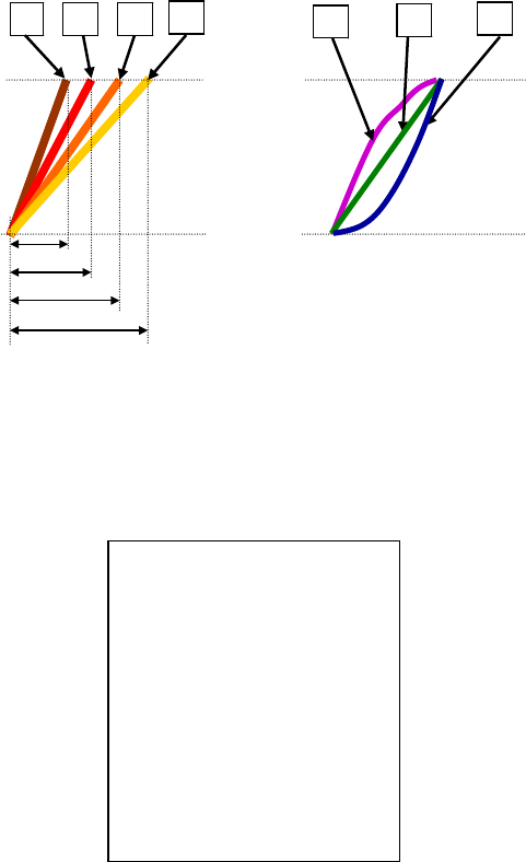
1. RADAR OPERATION
1-65
[CONDITION MENU]
1 BACK
2 SEA CONDITION
1/2/3/4/5
3 ANT HEIGHT
5/7.5/10/15/20/
25/30/35/40/45/
more50m
4 LOW LEVEL ECHO
0
3. Set items 1-6 and 8 referring to the following sections:
1 INT REJECT: 1.25 5 AUTO STC: 1.17
2 ECHO STRETCH: 1.26 6 AUTO RAIN: 1.18
3 ECHO AVERAGE: 1.27 8 PULSE: 1.15
4 NOISE REJ: 1.28
4. Select 7 VIDEO CONTRAST.
5. Select 1, 2, 3 or 4 (Dynamic Range) or A, B, C (Curve) as appropriate. Refer
to the description below and the illustration on the next page.
1-4: Control dynamic range. 1 provides the widest dynamic range; 4 is the
narrowest dynamic range.
A: Mid-level in the curve is low, so this setting is suitable for reducing rain
clutter.
B: Curve between A and C.
C: Mid-level in the curve is high, so this setting is suitable for detecting
distant targets.
5 db
7 db
9 db
11 db
4 3 2 1CBA
PICTURE level
VIDEO SIGNAL level
* *
* Default
Video contrast settings
6. Select 9 [CONDITION] then push the scrollwheel to show the CONDITION
menu.
CONDITION menu
7. Select 2 SEA CONDITION.
8. Select appropriate sea condition. The larger the number the rougher the sea
state.
1. RADAR OPERATION
1-66
9. Select 3 ANT HEIGHT.
10. Select appropriate radar antenna height (above the waterline).
11. If necessary, open the menu, select the ECHO menu and 9 STC RANGE to
adjust effective STC range. The setting range is –10 to +10. The larger the
number the longer the effective STC range becomes. Roll the scrollwheel to
set. (Note that the keyboard cannot be used to enter the setting.)
12. If necessary Select 4 LOW LEVEL ECHO to reject low level echoes. The
setting range is 0-8. The higher the figure the stronger the low level echo that
is erased.
13. To save a program, Select 0 DEFAULT.
14. Select SAVE and push the scrollwheel or left button.
15. Push the right button twice to close the menu.
Note: You may also program and save other picture setups.
1.35.3 Restoring user settings
If you get lost in operation while adjusting the settings for a picture setup, you
can easily restore user settings for that picture setup. Note that user settings are
deleted when default settings are restored.
1. Left-click the PICTURE box at the left side of the screen to select the picture
setup option for which you want to restore its user settings.
2. Push the right button to show the PICTURE menu.
3. Select 0 DEFAULT.
4. Select USER and push the left button or scrollwheel.
5. Push the right button to close the menu.
1.35.4 Restoring default picture setup options
Any of the radar functions programmed with the picture setup options may be
adjusted as desired. If you get lost in operation and want to restore the default
settings for a particular picture setup operation, do the following:
1. Left-click the PICTURE box at the left side of the screen to select the picture
setup option for which you want to restore its default settings.
2. Push the right button to show the PICTURE menu.
3. Select 0 DEFAULT.
4. Select FACTORY and push the left button or scrollwheel.
5. Push the right button to close the menu.

1. RADAR OPERATION
1-67
[PICTURE SELECT]
1 BACK
2 PICTURE SELECT
PICTURE1 OFF/ON
PICTURE2 OFF/ON
PICTURE3 OFF/ON
PICTURE4 OFF/ON
NEAR OFF/ON
FAR OFF/ON
NEAR BUOY OFF/ON
FAR BUOY OFF/ON
ROUGH SEA OFF/ON
SHIP OFF/ON
HARBOR OFF/ON
COAST OFF/ON
1.35.5 Disabling unnecessary picture setups
There are quite a few picture setups from which to select, some which you may
not require. You can disable unnecessary ones as follows:
1. Left-click the MENU box to open the menu.
2. Select 1 [ECHO].
3. Select 8 [PICTURE SELECT].
4. Select 2 PICTURE SELECT.
5. Select the picture setup you wish to disable and push the left button.
6. Select OFF or ON as applicable and push the left button.
7. Push the right button twice to close the menu.

1. RADAR OPERATION
1-68
[CUSTOMIZE•TEST]
1 BACK
2 [DATA BOX]
3 [F1]
4 [F2]
5 [F3]
6 [F4]
7 [OPERATION]
8 [TEST]
[F1]
1 BACK
2 [ECHO]
3 [STD KEY]
4 [TT•AIS]
5 [OPERATION]
6 [PICTURE]
1.36 Function Keys
Less-often used functions are provided in the menu. To avoid opening the
menus to set up the radar for a particular situation, function keys F1-F4 may be
assigned any of the functions shown in the CUSTOMIZE•TEST sub menu.
1.36.1 Activating function keys
To activate the function assigned to a function key, press the key to instantly set
the radar for the preset purpose. Further press the key to select option.
Function key Default setting
F1 Interference Rejector
F2 Echo Stretch
F3 Auto Rain
F4 Heading Line Off
1.36.2 Programming function keys
Do the following to program the function keys.
1. Left-click the MENU box to open the menu.
2. Select 9 [CUSTOMIZE•TEST] then push the scrollwheel.
CUSTOMIZE•TEST menu
3. Select 3 [F1], 4 [F2], 5 [F3] or 6 [F4], whichever function key you want to set,
For example, select 3 [F1] then push the left button.
F1 menu

1. RADAR OPERATION
1-69
[ECHO]
1 BACK
2
PICTURE/
IR
ES/
EAV/
NOISE REJ/
ANT SELECT/
PULSE LENGTH/
A/C SEA SELECT/
AUTO RAIN SELECT/
TUNE SELECT/
ANT HEIGHT/
SEA CONDITION/
2ND ECHO REJ/
PM/
SART
WIPER
[TT•
A
IS]
1 BACK
2
DISP TT/
DISP AIS/
TARGET DATA & ACQ/
PAST POSN INTERVAL/
REF MARK/
CPA LIMIT/
CPA/
TCPA/
AZ1/
AZ2/
TARGET LIST SORT/
TRIAL MANEUVER/
ASSOCIATION/
AIS MESSAGE/
TRIAL MODE CHANGE
AIS SCALED SYMBOL
[STD KEY]
1 BACK
2
ALARM ACK/
STBY TX/
HL OFF/
EBL OFFSET/
MODE/
OFF CENTER/
CU TM RESET/
PI LINE/
VECTOR TIME/
VECTOR MODE/
TARGET LIST/
TRAIL/
BRILL/
MARK/
MENU/
RANGE UP/
RANGE DOWN/
ACQ/
TARGET DATA/
TARGET CANCEL
[OPERATION]
1 BACK
2
ECHO COLOR/
PALETTE/
RING/
ALARM1/
ALARM2/
WATCH ALARM RESET/
ZOOM/
MARK DELETE/
OWN TRACK DELETE/
TGT TRACK DELETE*/
CHART ALIGN/
DISPLAY SELECT/
RADAR COMBINE*/
MOB/
USER DEFAULT
TLL*/
ANCHOR WATCH/
COLOR SHIFT/
ICON/ DISP*/
OWN TRK ALL ERASE
TGT TRK ALL ERASE*
MARK ALL ERASE
DROP MARK
4. Select appropriate category, ECHO, STD KEY, TT•AIS, OPERATION or
PICTURE. Refer to the menus below to select appropriate category.
* Not available on IMO type
[PICTURE]
1 BACK
2
PICTURE1/
PICTURE2/
PICTURE3/
PICTURE4/
NEAR/
FAR/
NEAR BUOY/
FAR BUOY/
ROUGH SEA/
SHIP/
HARBOR
COAST

1. RADAR OPERATION
1-70
5. Select "2".
6. Select function desired then push the scrollwheel or left button.
7. Push the right button twice to close the menu.
Description of function key programs
Item Description
[ECHO]
PICTURE Selects picture setup function.
IR Selects interference rejection level.
ES Selects echo stretch function.
EAV Selects echo averaging function.
NOISE REJ Turns noise rejector on/off.
ANT SELECT Selects antenna.
PULSE LENGTH Selects pulselength.
A/C SEA SELECT Selects A/C SEA adjustment method.
AUTO RAIN SELECT Selects AUTO RAIN level.
TUNE SELECT Selects tuning adjustment method.
ANT HEIGHT Sets antenna height.
SEA CONDITION Sets sea condition.
2ND ECHO REJ Turns 2nd trace echo rejector on/off.
PM Turns performance monitor on/off.
SART Turns SART setup conditions on/off.
WIPER Turns wiper (reduce weak and unwanted signals) on/off.
[STD KEY]
ALARM ACK Acknowledges alarm. (Silences audio alarm.)
STBY TX Toggles between stand-by and transmit.
HL OFF Turns heading line on/off.
EBL OFFSET Offsets EBL.
OFF CENTER Off centers the display.
CU TM RESET Returns own ship mark to point 75% of range in use.
PI LINE Turns PI line on/off.
VECTOR TIME Sets vector time.
VECTOR MODE Sets vector mode.
TARGET LIST Displays target list.
TRAIL Sets trail parameters.
BRILL Sets brilliance.
MARK Selects mark to inscribe.
MENU Opens the MAIN menu.
RANGE UP Raises the range scale.
RANGE DOWN Lowers the range scale.
ACQ Acquires target; activates sleeping AIS target.
TARGET DATA Shows target data for selected tracked target or AIS target.
TARGET CANCEL Cancels tracking of tracked target; sleeps AIS target.

1. RADAR OPERATION
1-71
Description of function key programs (con’t from previous page)
Item Description
[TT•AIS]
DISP TT Activates/deactivates TT.
DISP AIS Activates/deactivates AIS.
TARGET DATA & ACQ TT: Acquires target; shows data for tracked target selected.
AIS: Activates sleeping AIS target; shows data for AIS target
selected.
PAST POSN INTERVAL Selects past position plotting interval.
REF MARK Inscribes reference mark (for target-based speed).
CPA LIMIT Turns CPA limit on/off.
CPA Enters CPA range.
TCPA Enters TCPA time.
AZ1 Sets Alarm Zone 1.
AZ2 Sets Alarm Zone 2.
TARGET LIST SORT Sorts target list.
TRIAL MANEUVER Executes trial maneuver.
ASSOCATION Changes indication in Association Usage box. See 4.13.
AIS MESSAGE Displays AIS message board.
TRIAL MODE CHANGE Switches between dynamic and static modes.
AIS SCALED SYMBOL Scales AIS target symbols according to target (ship) size.
[OPERATION]
ECHO COLOR Selects echo color.
BACK COLOR Selects background color.
RING Turns range rings on/off.
ALARM1 Sets no. 1 target alarm.
ALARM2 Sets no. 2 target alarm.
WATCH ALARM RESET
Resets watch alarm.
ZOOM Enables zoom.
MARK DELETE Deletes mark (origin mark, waypoint mark, plotter mark).
OWN TRACK DELETE Deletes own ship’s tracks according to setting of OWN TRACK
menu (see page 5-15).
TGT TRACK DELETE Deletes other ship’s tracks according to setting of TARGET TRACK
menu (see page 5-15).
CHART ALIGN Aligns chart with radar picture.
DISPLAY SELECT Selects display mode.
RADAR COMBINE* Dual-radar display. *Non-IMO only
MOB Inscribes MOB mark.
USER DEFAULT Restores user defaults for [F1]-[F3].
For F-KEY:
1. Set equipment as desired.
2. Long-push (more then 1 s) function key registered as USER
DEFAULT.
3. To recall a setting, do step 2. The radar is then set to stand-by
and "USER DEFAULT" appears at the bottom-right corner.
For STORE:
1. Set equipment as desired.
2. Select STORE at 2 USER DEFAULT BACKUP from page (2/2)
of the OPERATION menu. Select HOLD to register settings.
3. To recall setting, press the function key registered as USER
DEFAULT. The radar is then set to stand-by and "USER
DEFAULT" appears at the bottom-right corner.
TLL Target latitude and longitude output (to chart plotter).
ANCHOR WATCH Enables the anchor watch alarm.
COLOR SHIFT Paint own ship's tracks in different colors.
ICON DISP Hides and shows boxes outside the effective display area.
1. RADAR OPERATION
1-72
[OS POSN MENU]
1 NAV AID
GPS1/GPS2/
DEAD RECKONING/
LAN
2 MANUAL L/L
00°00.00 N
000°00.00 W
3 SIO DATA LAN OUTPUT
OFF/ON
Item Description
[OPERATION] (con't from previous page)
OWN TRK ALL ERASE Erases all own ship’s tracks.
TGT TRK ALL ERASE Erases all other ship’s tracks.
MARK ALL ERASE Erases all marks.
DROP MARK Inscribe a drop mark.
[PICTURE]
PICTURE1 – PICTURE4 Actuates settings of user-programmed setup.
NEAR Optimum setting for short range detection using a range scale of 3
nm or less on calm seas
FAR Optimum setting for long range detection using a range scale of 6
nm or larger
NEAR BUOY Optimum setting for detecting navigation buoys, small vessels and
other small surface objects at close range
FAR BUOY Optimum setting for detecting navigation buoys, small vessels and
other small surface objects at long range
ROUGH SEA Optimum setting for rough weather or heavy rain
SHIP Optimum setting for detecting vessels
HARBOR Optimum setting for harbor navigation
COAST Optimum setting for coastal navigation
1.37 Ship’s Position
Select the source of ship’s position data as follows:
1. Right-click the OSN POSN box at the top right corner of the screen to show
the OS POSN menu.
OS POSN menu
2. Select 1 NAV AID.
3. Select GPS1, GPS2 or DEAD RECKONING as appropriate.
GPS1: GPS navigator connected to nav port
GPS2: GPS navigator connected to SPEED LOG port or TRACK CONTROL
port.
1. RADAR OPERATION
1-73
4. If you have selected DEAD RECKONING do the following to enter position
manually. For GPS1 or GPS2, go to step 6.
a) Select 2 MANUAL L/L then push the scrollwheel. Enter latitude and longitude
position as follows.
b) Roll the scrollwheel to set appropriate digit in the latitude field then push the
scrollwheel. (You may push the scrollwheel again to skip a place.) For
keyboard operation, press appropriate numeric keys then press the [ENTER
MARK] key.
c) Set longitude similar to how you set latitude then push the scrollwheel. (For
keyboard operation, press the [ENTER MARK] key.)
Note: Co-ordinate polarity may be switched by rolling the scrollwheel, or
pressing the [2] key.
5. To use a navigation device connected to radars via a LAN, set 3 SIO DATA
LAN OUTPUT to ON, then select LAN at 1 NAV AID.
6. Push the right button to close the menu.
Note: When the AIS function is active, DEAD RECKONING is shown in gray to
indicate that it is not available for selection.
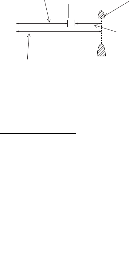
1. RADAR OPERATION
1-74
1.38 Second-trace Echoes
In certain situations, echoes from very distance targets may appear as false
echoes (second-trace echoes) on the screen. This occurs when the return echo
is received one transmission cycle later, or after a next radar pulse has been
transmitted.
Second-trace
echo
Tx repetition
Actual range
False echo
range
Second-trace echoes
To reject second-trace echoes:
1. Left-click the MENU box to open the menu.
2. Select 1 [ECHO] to open the ECHO menu.
[ECHO]
1 BACK
2 2
ND
ECHO REJ
OFF/ON
3 TUNE INITIALIZE
4 PM
OFF/ON
5 SART
OFF/ON
6 WIPER
OFF/1/2
7 ECHO AREA*
1
CIRCLE/WIDE/ALL
*1 Not available on IMO or A type
8 [PICTURE SELECT]
9 STC RANGE
+00
ECHO menu
3. Select 2 2ND ECHO REJ.
4. Select OFF or ON as appropriate.
5. Push the right button twice to close the menu.
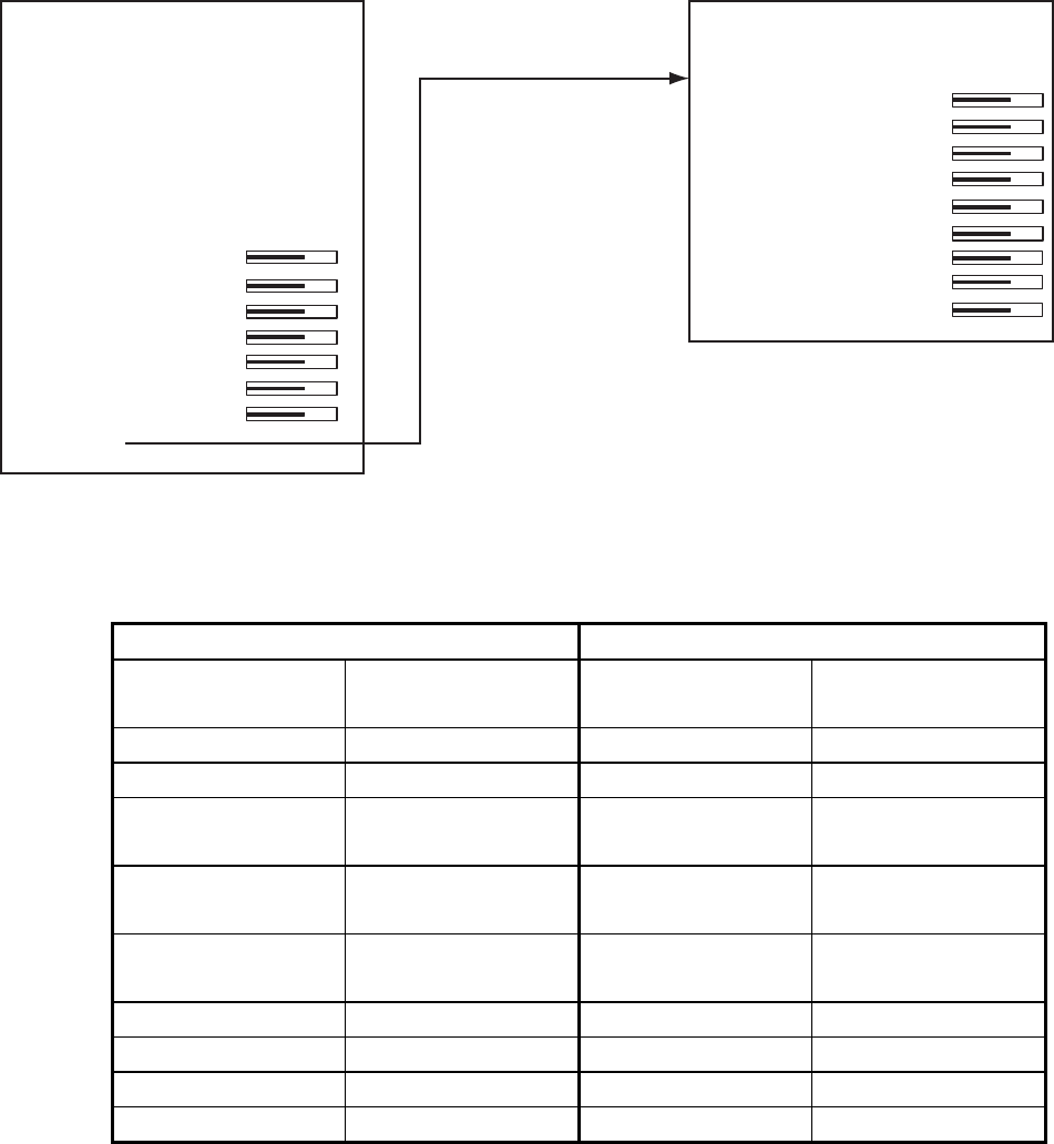
1. RADAR OPERATION
1-75
1.39 Brilliance of Screen Data
You can adjust relative brilliance levels of various markers and alphanumeric
readouts displayed on the screen.
1. Right-click the BRILL box at the bottom left corner of the screen to show the
BRILL menu.
[BRILL1 MENU (2/2)]
1 BACK
2 BRG CURSOR
3 EBL
4 VRM
5 PI LINE
6 TT SYMBOL
7 AIS SYMBOL
8 L/L GRID
9 MARK
0 CHART*
Choose 0 NEXT
to show page 2
of the BRILL menu.
[BRILL1 MENU (1/2)]
1 ECHO COLOR
YEL/GRN/
WHT/COLOR*
2 PALETTE
DAY-GRY/DAY-BLU/
DUSK-GRY/DUSK-BLU/
NIGHT-GRY/NIGHT-BLU/
3 PANEL DIMMER
4 CHARACTER
5 CURSOR
6 ECHO
7 TRAIL
8 HL
9 RING
0 NEXT
* Not available
on IMO or A type
Note: Four brilliance and color sets are
provided. For further details see
section 1.49.
BRILL menu
2. Select item you wish to adjust. (To go to the second page of the BRILL menu
select 0 NEXT and push the scrollwheel.)
Page 1 Page 2
Item Adjusts
brilliance of;
Item Adjusts
brilliance of;
1 ECHO COLOR See section 1.49. 2 BRG CURSOR Bearing cursor
2 PALETTE See section 1.49. 3 EBL EBLs
3 PANEL
DIMMER
Backlighting of
control unit
4 VRM VRMs
4 CHARACTER All alphanumeric
characters
5 PI LINE PI lines
5 CURSOR Cursor (+) and
arrow
6 TT SYMBOL
TT symbols
6 ECHO Radar echoes 7 AIS SYMBOL AIS symbols
7 TRAIL Target trails 8 L/L Chart grid
8 HL Heading line 9 MARK All marks
9 RING Range rings 0 CHART Chart
3. Roll the scrollwheel to set brilliance level. The range of adjustment for items
except "HL" and "CURSOR" is 0-100%. The range of adjustment for HL and
CURSOR is 50-100%.
4. Push the right button once or twice to close the menu.

1. RADAR OPERATION
1-76
[ALARM]
1 BACK
2 TARGET ALARM MODE
IN/OUT
3 TARGET ALARM MODE
1/2/3/4
4 WATCH ALARM
OFF/6M/10M/
12M/15M/20M
5 ALARM SOUND LEVEL
OFF/LOW/MID/HIGH
6 [ALARM OUT1]
7 [ALARM OUT2]
8 [ALARM OUT3]
9 [ALARM OUT4]
0 [PRIMARY ALARM]
1.40 Watch Alarm
The watch alarm sounds the audio alarm at the selected time interval to help you
keep regular watch of the radar picture for safety or other purposes.
The WATCH box appears at right side of the screen with a watch alarm timer
counts down from value set (for example, "12:00").
WATCH
12:00
WATCH box
When a preset time interval has elapsed, the audible watch alarm is released,
the screen label WATCH turns red and the watch alarm timer freezes at "0:00."
To silence the alarm, press the [ALARM ACK] key on the full keyboard or
left-click the ALARM ACK box. The label WATCH turns to normal color and the
watch alarm timer is reset to the initial value and starts the count-down
sequence again.
If you press the [ALARM ACK] key or click the box with the left button before the
selected time interval is reached, the watch alarm timer is reset to the initial
value and starts the count-down sequence again.
To set watch time interval:
1. Left-click the MENU box to open the menu.
2. Select 3 [ALARM] to open the ALARM menu.
ALARM menu
3. Select 4 WATCH ALARM.
4. Select appropriate time interval then push the right button twice to close the
menu.

1. RADAR OPERATION
1-77
[NAV DATA]
1 BACK
2 DEPTH
OFF/m/ft
3 DEPTH GRAPH SCALE
10/20/50/
100/200/500
4 DEPTH MARK
000
5 CURRENT
OFF/ON
6 WIND
OFF/m/s/kn
RELATIVE/
TRUE THEORETICAL/
TRUE NORTH
7 TEMP
OFF/ON
8 DATE-TIME
OFF/UTC/LOCAL
9 LOCAL TIME ADJ
+00:00
0 WPT DATA
OFF/REL/TRUE
1.41 Nav Data
Wind, depth, ocean current, water temperature, date and time and waypoint data
may be set up as follows:
1. Left-click the MENU box to open the menu.
2. Select 7 [NAV DATA].
NAV DATA menu
3. Select appropriate options referring to the table on the next page for details.
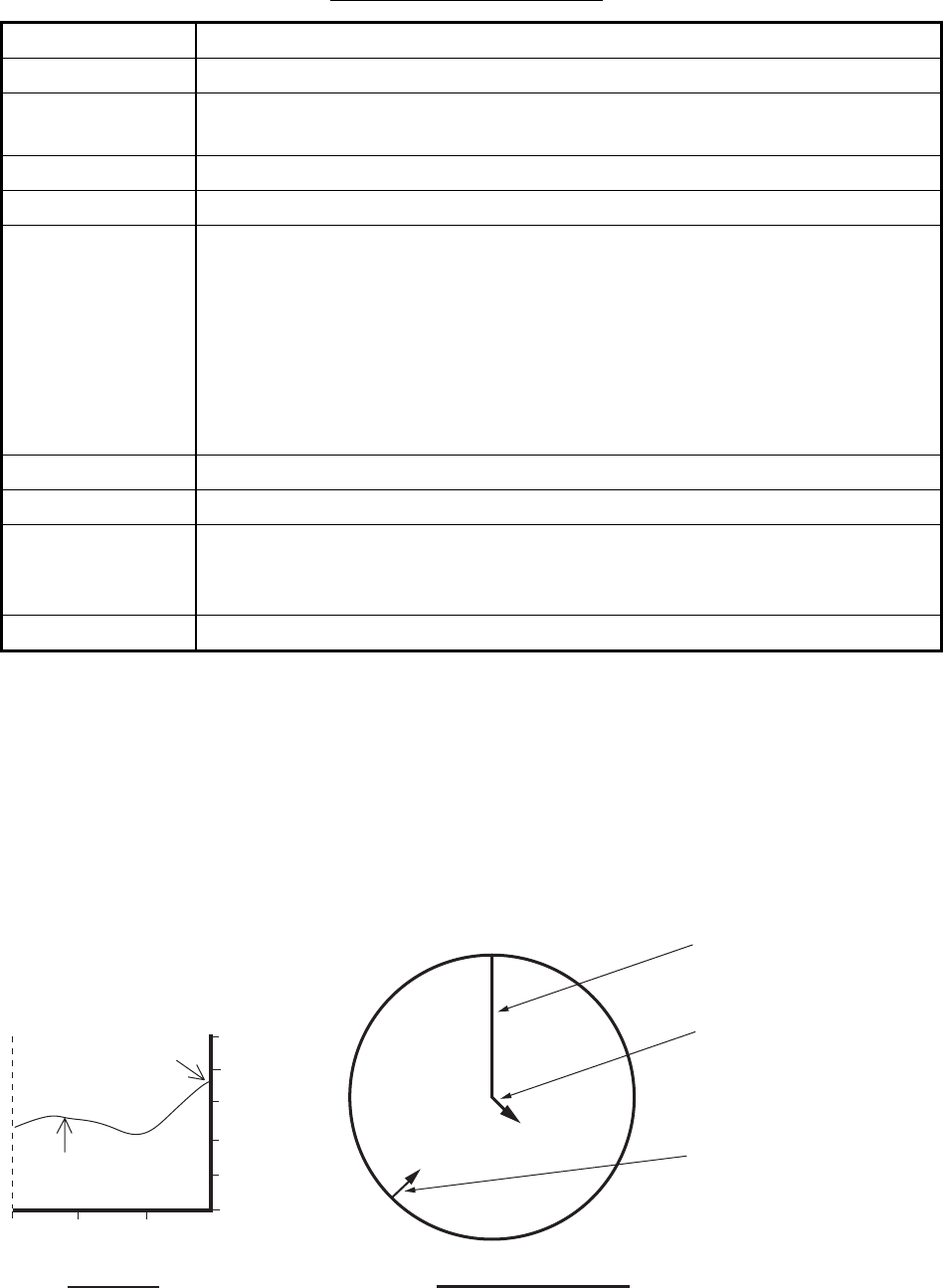
1. RADAR OPERATION
1-78
Nav data menu description
Item Description
2 DEPTH Selects unit of depth measurement, or turn depth indication off.
3 DEPTH
GRAPH SCALE
Selects depth scale range. The echogram shows the last 30 minutes of
sounding along the ship’s track.
4 DEPTH MARK Selects the depth at which to show the depth mark.
5 CURRENT Turns ocean current display on (ocean current relative to North) or off.
6 WIND Selects unit of wind speed measurement/wind speed format. Wind vector
format can be selected from three choices:
RELATIVE: Apparent wind measured by wind meter, with ship's bow as
reference.
TRUE THEORETICAL: Apparent wind minus ship's movement, with ship's
bow as reference.
TRUE NORTH: Apparent wind minus ship's movement, with North as
reference.
7 TEMP Turns water temperature indication on/off.
8 DATE-TIME Selects how to display date and time: OFF, UTC or LOCAL.
9 LOCAL TIME
ADJ
If LOCAL is selected at 8 DATE-TIME, roll the scrollwheel to set the time
difference between local time and UTC time. A negative value may be
selected by spinning the scrollwheel past zero.
0 WPT DATA Turn waypoint data off or select waypoint data reference, true or relative.
4. Push the right button twice to close the menu.
Note: Wind and current data require appropriate sensors. Depth data requires
appropriate echo-sounding equipment. Wind vector shows a direction from
which the wind blows in, relative to own ship heading, and labeled "T *." Wind
velocity is a true wind speed as a result of compensating for own ship’s speed
and orientation. Ocean current (tide) is shown relative to bow in head-up, cursor
gyro and course-up, and reference to North in north-up and true motion.
30 20 10 min 100 m
80
60
40
20
0
Present depth
Last 30 minutes
of depth
N
E
W
S
OS heading
Wind direction indication
method depends on the
MENU Selection of Wind
Vector.
Echogram Wind, current graph
Current relative to north,
full scale 10 kn.
Examples of depth echogram and wind, tide graph

1. RADAR OPERATION
1-79
[CUSTOMIZE•TEST]
1 BACK
2 [DATA BOX]
3 [F1]
4 [F2]
5 [F3]
6 [F4]
7 [OPERATION]
8 [TEST]
[DATA BOX]
1 BACK
3 NAV DATA
OFF/ON
4 ZOOM
OFF/2TIMES/3TIMES
5 ZOOM DISPLAY
STAB GND/STAB HGD/
STAB NORTH/
TT TRACK
6 TARGET DATA
1BOX/2BOX/3BOX/
LARGE
1.42 Text Window
The text window, displayed at the right 1/4 of the screen, mainly shows nav data,
zoomed target, and tracked target data. You can set up this window as follows:
1. Left-click the MENU box to open the menu.
2. Select 9 [CUSTOMIZE•TEST]
CUSTOMIZE•TEST menu
3. Select 2 [DATA BOX].
DATA BOX menu
4. Select 3 NAV DATA.
5. Select OFF or ON as appropriate.
6. Select 4 ZOOM.
7. Select OFF or zoom magnification factor (2TIMES or 3 TIMES).
8. If you selected a zoom factor at step 7, go to step 9. Otherwise, go to step
11.
9. Select 5 ZOOM DISPLAY.

1. RADAR OPERATION
1-80
10. Select zoom display format.
STAB GND: Ground stabilized (geographically Fixed)
STAB HDG: Heading stabilized (relative)
STAB NORTH: North stabilized (true)
TT TRACK: Zoom tracked targets.
11. Select 6 TARGET DATA.
12. Select quantity of tracked target data to show among 1BOX, 2BOX, 3BOX
and LARGE.
Note: Nav data or zoom is
automatically removed
when "3BOX" is selected.
LARGE
Nav Data or Zoom
TT, AIS Functions
Box
Warnings, Alerts
Guidance Box
1 BOX
Zoom
Nav Data or Zoom
TT, AIS Functions
Box
Warnings, Alerts
Guidance Box
1 BOX
2 BOX
Nav Data or Zoom
TT, AIS Functions
Box
Warnings, Alerts
Guidance Box
1 BOX
2 BOX
3 BOX
TT, AIS Functions
Box
Warnings, Alerts
Guidance Box
1 BOX 2 BOX
3 BOX LARGE
Tracked data setting and data box arrangement
13. Push the right button three times to close the menu.

1. RADAR OPERATION
1-81
[CUSTOMIZE•TEST]
1 BACK
2 [DATA BOX]
3 [F1]
4 [F2]
5 [F3]
6 [F4]
7 [OPERATION]
8 [TEST]
[OPERATION]
1 BACK
2 WHEEL DRIVE
NORMAL/REVERSE
3 KEY BEEP
OFF/LO/MID/HI
4 REMOTE KEY
F*-KEY/
DISPLAY SELECT
5 POP UP GUIDANCE*
OFF/ON
6 OWN SHIP VECTOR
OFF/HDG/COURSE
7 STERN-UP
OFF/ON
8 SHUTTLE FERRY
OFF/MODE1/MODE2
0 NEXT
1.43 Customizing Operation
Several operation items may be customized to suit your needs.
1. Left-click the MENU box to open the menu.
2. Select 9 [CUSTOMIZE•TEST] to open the CUSTOMIZE•TEST menu.
CUSTOMIZE•TEST menu
3. Select 7 [OPERATION].
* Not available on IMO or A type
OPERATION menu
4. Set each item as appropriate, referring to the table on the next page for
details.
5. Push the right button to close the menu.

1. RADAR OPERATION
1-82
Operation menu items
Item No. Description Options
2 WHEEL DRIVE
Select how to cycle data when
using the scrollwheel.
NORMAL: Cycles numeral
data in numeric order and
indication data in clockwise
order.
REVERSE: Reverse of
NORMAL.
3 KEY BEEP
Key beeps when key sequence
has been correctly executed.
OFF: No key beep
LO, MID, HI: Loudness of
key beep
4 REMOTE KEY Select function of keys F1-F4
on control unit.
F*-KEY: Operates as
function key.
DISPLAY: Control unit
operates radar it is
connected to.
5 POP UP
GUIDANCE
(Available on B, C
and W types)
Pop up guidance You may turn the guidance
off or on.
6 OWN SHIP
VECTOR
Select what the own ship vector
displays.
OFF: No own ship vector
HDG: Vector shows heading
direction.
COURSE: Vector shows
course.
7 STERN-UP
Enables/disables the stern-up
presentation mode.
ON: Enables stern-up mode.
OFF: Disables stern-up
mode.
8 SHUTTLE
FERRY
Turns shuttle ferry mode on or
off.
OFF: Disables shuttle ferry
mode.
MODE1: Head-up picture is
rotated 180°.
MODE2: Head-up picture is
rotated 180° and the gyro
reading has 180° added to it
or subtracted from it.

1. RADAR OPERATION
1-83
1.44 Alert Box
When error or alarm setting violation is found, the applicable indication appears
(red, flashing) in the Alert Box and the buzzer sounds. The Alert Box is
composed of four lines of information, as shown below.
Silence the buzzer with the [ALARM ACK] key or select the ALARM ACK box
then push the left button. The buzzer and the flashing stop but the alarm
indication remains on the display until the reason for the alarm is removed.
Display Example 1: ERROR and WARNING
Display Example 2: ERROR only
Display Example 3: ERROR and WARNING
Alert Box Configuration
(lines inside box not present in actual box)
- - - - - SYSTEM ERROR - - - - -
VIDEO
- - - - - - WARNING - - - - - -
FORMAT CARD DATA
- - - - AIS ALARM MESSAGE - - - -
AIS: no valid ROT info
rmation
- - - - AIS ALARM MESSAGE - - - -
AIS: no valid ROT info
- - - - - - WARNING - - - - - -
RD CARD DATA
Line 1: Name of ERROR or ALARM category
Line 2: Name of error or alarm
Line 3: Message Category WARNING
Line 4: Name of warning

1. RADAR OPERATION
1-84
1.44.1 Alarm description
Alarm description
Alarm name
(visual
indication)
Visual alarm, reason To quit alarm status
SYSTEM ERROR
AZIMUTH No antenna rotation signal
HEADLINE No heading signal
KEY No key signal
RF No RF communications signal
TRIGGER No trigger signal
TT SYSTEM
ERROR
TT system malfunction
VIDEO No video signal
Acknowledge indication by pressing
the [ALARM ACK] key or left-clicking
the ALARM ACK box. Restore signal
or remove reason for to remove
indication.
SENSOR ERROR
GYRO The indication "GYRO" (in red)
appears and the HDG indication
reads "***.*°". The orientation
mode is automatically set for
head-up. TT, radar map, AIS, and
echo averaging are disabled.
Match the on-screen HDG indication
with the actual compass. The
indication "HEADING SET" appears.
Press the [ALARM ACK] key to erase
the indication.
LOG The indication "LOG" (in red)
appears and the and the speed
indication shows "**.* kn" if the
speed signal is lost more than
30 s. For BT error, CPA and
TCPA for AIS are not calculated.
If the SDME has failed, use another
speed sensor.
EPFS The indication "EPFS" (in red)
appears and the position display
shows all asterisks if the position
input is lost more than 30 s.
Radar map, AIS, and echo
averaging are disabled.
Acknowledge indication by pressing
the [ALARM ACK] key or left-clicking
the ALARM ACK box. Restore signal
to remove indication. Message cannot
be erased if position signal is missing;
it is automatically erased when the
signal is restored.
DATUM For the IMO type, the indication
"DATUM" (in red) appears if the
datum is other than WGS-84 or
WGS-84 is not input. AIS is
inoperative with datum other than
WGS-84.
Acknowledge indication by pressing
the [ALARM ACK] key or left-clicking
the ALARM ACK box. Use WGS-84
datum.

1. RADAR OPERATION
1-85
Alarm name
(visual
indication)
Visual alarm, reason To quit alarm status
AIS ALARM (See section 4.15.)
DUAL RADAR ALARM (Non-IMO only)
EXT RADAR
STBY
External radar is in standby Set external radar in transmit to erase
indication.
EXT RADAR
ERROR
External radar malfunction Restore external radar to normal
condition to erase indication.
EXT RADAR
HDG SET
Problem with heading data at
external radar.
Re-set external radar's heading data
to erase indication.
OTHER ALARM
ANCHOR
WATCH
Ship has drifted more than a
threshold value.
Acknowledge indication by pressing
the [ALARM ACK] key or left-clicking
the ALARM ACK box.
ARRIVAL Own ship has arrived to a
waypoint.
Acknowledge indication by pressing
the [ALARM ACK] key or left-clicking
the ALARM ACK box.
CHECK INT-SW Interswitch malfunction Acknowledge indication by pressing
the [ALARM ACK] key or left-clicking
the ALARM ACK box. Check
interswitch.
DEPTH Depth is lower or higher than
threshold value.
Acknowledge indication by pressing
the [ALARM ACK] key or left-clicking
the ALARM ACK box.
HEADING SET Heading signal has been
restored.
Press the [ALARM ACK] key to erase
the message. Match the on-screen
HDG readout with the actual compass
reading, if necessary.
MEMORY CARD
FULL
Memory card is full Acknowledge indication by pressing
the [ALARM ACK] key or left-clicking
the ALARM ACK box.
TARGET ALARM A target has entered (or exited)
the target alarm zone. Target
flashes.
Acknowledge indication by pressing
the [ALARM ACK] key or left-clicking
the ALARM ACK box.
WATCH WATCH 0:00
(WATCH appears and time count
freezes at 0:00).
Press the [ALARM ACK] key or click
the WATCH box with the left button.
The WATCH box is displayed in
normal video and the timer is reset.
XTE Own ship is off course more than
threshold value.
Acknowledge indication by pressing
the [ALARM ACK] key or left-clicking
the ALARM ACK box.

1. RADAR OPERATION
1-86
Alarm name
(visual
indication)
Visual alarm, reason To quit alarm status
TT ALARM (See section 3.15.)
WARNING
AIS
TRANSMITTING
AIS transponder is transmitting.
CABLE ATT ADJ Adjustment (at installation)
according to length of antenna
cable.
DELETE CARD
DATA
Deleting data from memory card.
FORMAT CARD
DATA
Formatting memory card.
PM Performance monitor active
POWER
RESTART
Loading installation settings from
memory card.
RD CARD DATA Reading from memory card.
SART Radar set up to receive SART.
TUNE
INITIALIZE
Initializing tuning.
USER DEFAULT Restoring user defaults.
WR CARD DATA Writing to memory card.
Indication disappears when
procedure is completed.
Note 1: It is not possible to acknowledge the radar critical alarms from external equipment
without displaying the reason/cause for the alarm. Radar critical alarms are TT COLLISION
and AIS COLLISION.
Note 2: This radar does not receive alarm information from external alarm systems.

1. RADAR OPERATION
1-87
1.44.2 Alarm list
The alarm list displays the names of violated alarms, including the time and date
violated. A maximum of 28 alarms are shown, on four pages. Unacknowledged
alarms are displayed first in the list (in red text), in the order in which they appear
in the Alert Box.
An unacknowledged alarm can be acknowledged from the list by selecting its
number and hitting the left button. To erase the data for the number selected, hit
the left button again. To erase all alarm indications, select 9 REFRESH DATA
and long-push the left button.
To display the alarm list, put the cursor in the Alert Box and push the right button.
[ALARM LIST (1/1)]
1 BACK (L=TOP)
2 - - - SENSOR ERROR - - -
EPFS
03/APR/2008 09:34
3 - - - AIS ALARM - - -
AIS NEW TARGET
03/APR/2008 08:02
4 - - - SENSOR ERROR - - -
LOG
03/APR/2008 07:18
5 - - - PRIMARY ALARM - - -
TT COLLISION
03/APR/2008 06:50
6 - - - - TT ALARM - - - -
TT LOST
03/APR/2008 06:43
7 - - - OTHER ALARM - - -
DEPTH
02/APR/2008 23:53
8 - - - OTHER ALARM - - -
WATCH
02/APR/2008 20:00
9 REFRESH DATA (L=CLR)
0 NEXT
Alarm category*
Alarm name
Date and time of violation
* AIS ALARM
DUAL RADAR ALARM
OTHER ALARM
PRIMARY ALARM
SENSOR ERROR
SYSTEM ERROR
TT ALARM
• When there is more than one alarm page you can switch between them with 0
NEXT and 0 BACK (last page).
• ZDA sentence required in order to display time in Alarm list.

1. RADAR OPERATION
1-88
[ALARM]
1 BACK
2 GUARD ALARM MODE
IN/OUT
3 GUARD ALARM LEVEL
1/2/3/4
4 WATCH ALARM
OFF/6M/10M/
12M/15/20M
5 ALARM SOUND LEVEL
OFF/LOW/MID/HIGH
6 [ALARM OUT1]
7 [ALARM OUT2]
8 [ALARM OUT3]
9 [ALARM OUT4]
0 [PRIMARY ALARM]
[ALARM OUT1]
1 BACK
2
TARGET ALARM
WATCH ALARM
TT NEW TARGET
TT LOST TARGET
TT CPA LIMIT
TT AUTO ACQ TGT FULL
TT MAN ACQ TGT FULL
TT SYSTEM ERROR
AIS NEW TARGET
AIS LOST TARGET
AIS CPA LIMIT
AIS TGT FULL
AZIMUTH
HEAD LINE
TRIGGER VIDEO
GYRO LOG EPFS
XTE
ARRIVAL WPT
DEPTH
ALARM ACK OUT
OPERATOR FITNESS
ANCHOR WATCH
NO CPA/TCPA FOR AIS
9 ALARM OUT POLARITY
NORMAL/INVERT
1.44.3 Outputting alarm signals
Four ports are provided from which to output alarm signals to external equipment.
Select the port and alarm signals to output as follows:
1. Left-click the MENU box to open the menu.
2. Select 3 [ALARM].
ALARM menu
3. Select appropriate "ALARM OUT" item (6-9).
ALARM OUT1, 2: Normally closed
ALARM OUT3, 4: Normally open
4. Select an alarm to output. The alarm
selected is underlined.
5. Repeat step 5 to select other alarms to
output.
6. Push the right button three times to close the
menu.
ALARM OUT1 menu

1. RADAR OPERATION
1-89
[PRIMARY ALARM]
1 BACK
2
TARGET ALARM
WATCH ALARM
TT NEW TARGET
TT LOST TARGET
TT AUTO ACQ TGT FULL
TT MAN ACQ TGT FULL
AIS NEW TARGET
AIS LOST TARGET
AIS TGT FULL
XTE
ARRIVAL WPT
DEPTH
ANCHOR WATCH
NO CPA/TCPA FOR AIS
1.44.4 Primary alarm
Violated alarms appear in the Alert Box in the order of priority shown in the table
below.
Priority Alarm group Alarms
1 Error (sensor
and system)
Azimuth, Datum EPFS, Gyro, Headline, Key, Log, RF,
Trigger, TT System Error, Video
2 Primary See the PRIMARY ALARM menu below. TT CPA LIMIT
and NO CPA/TCPA FOR AIS are ON in default.
3 Other alarms Any alarm not listed here.
If desired you can assign primary alarms the same priority as Error alarms.
1. Left-click the MENU box to open the menu.
2. Select 3 [ALARM].
3. Select 0 [PRIMARY ALARM].
PRIMARY ALARM menu
4. Select alarm(s) for which you want to give priority equal to that of Error
alarms. Selected alarms are underlined.
5. Press the right button several times to close the menu.
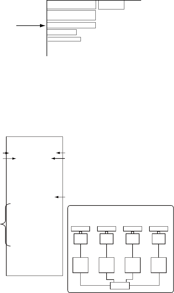
1. RADAR OPERATION
1-90
1.45 Interswitch
The interswitch of this radar uses an Ethernet to transfer video and control
signals. A digital signal transfers the video and control signals. You can connect
four antennas and eight display units. Set radar display and antenna groups
from the ANTENNA SELECT display.
When you switch to a different antenna, the heading skew and timing adjustment
(set at installation) for that antenna is automatically applied.
The ANTENNA box at the upper left position shows current antenna selection.
6
HEAD UP TB RM
ANT1M X-BAND
PULSE S1
PICTURE4
NM
/1 DISPLAY
RADAR
ANTENNA Box
- ANT1: Antenna no.
- M: Master (or S for Slave)
- X-band (or S-band)
1.45.1 Displaying antenna information
The ANTENNA SELECT display shows:
• Radar band, output power and antenna position of each antenna currently
powered. (If an antenna is not powered, its data area is blank.)
• Current antenna and display combinations.
• Your radar number
To show the ANTENNA SELECT display, right-click the ANTENNA.
[ANT SELECT]
ANT1: X-BAND
12 FORE
ANT2: X-BAND
12 MAIN TOP
ANT3: X-BAND
MAIN TOP
12
ANT4: X-BAND
AFT
OWN RADAR No.: 2
1 DISP1 ANT1
MASTER
2 DISP2 ANT2
MASTER
Antenna no.
Output power
(kW)
Radar band (X or S)
Radar antenna position (set at installation)
(FORE, MAIN TOP,MAIN 2ND,
MAIN 3RD,
AFT, PORT, STARBOARD)
* Not available on IMO
or A radar.
9 STORE INTER-SW
NO/YES
0 SUB MONITOR*
OFF/ON
Own radar no.
Current display and
antenna combinations
Using the information displayed in this
example, the antenna system configuration
would look like this.
ANT1 ANT2 ANT3 ANT4
DISP1 DISP2 DISP3 DISP4
HUB
3 DISP3 ANT3
MASTER
4 DISP4 ANT4
MASTER
12

1. RADAR OPERATION
1-91
1.45.2 Presetting antenna and display combinations
You can preset the antenna and display combinations for each antenna and
display in the radar system. As an example, the procedure below shows how to
select the no. 1 antenna unit for the no. 2 display unit.
1. Right-click the ANTENNA box to show the ANT SELECT display.
[ANT SELECT]
ANT1: X-BAND
12 FORE
ANT2: X-BAND
12 MAIN TOP
ANT3: X-BAND
MAIN TOP
12
ANT4: X-BAND
AFT
OWN RADAR No.: 2
1 DISP1 ANT1
MASTER
2 DISP2 ANT2
MASTER
* Not available on IMO or
A radar.
9 STORE INTER-SW
NO/YES
0 SUB MONITOR*
OFF/ON
3 DISP3 ANT3
MASTER
4 DISP4 ANT4
MASTER
12
2. Select the display unit for which to select an antenna (at the next step). For
example, select 2 DISP2 to select the no. 2 display unit.
3. The cursor is now selecting the current display and antenna combination for
the no. 2 display unit. Roll the scrollwheel to display ANT1 MASTER and
push the left button.
4. Repeat step 3 and 4 to set other display and antenna combinations.
5. Select 0 STORE INTER-SW.
6. Select YES to save display and antenna combinations.
7. Push the right button twice to close the menu.
Selection considerations
• A antenna unit cannot be controlled from multiple display units. Select one
MASTER display unit for one antenna unit. If two antenna units are set as
masters, the display last-set as master becomes the master and all other
displays are automatically changed to slave.
• An antenna unit without a MASTER display cannot be selected on the sub
display units. If there is no antenna unit set as master, the lowest number
display is automatically set as master.

1. RADAR OPERATION
1-92
• Radar functions are controlled independently, dependently or commonly
depending on selection as Master or Slave.
RADAR FUNCTIONS CONTROL MASTER DISPLAY OPTION SLAVE DISPLAY OPTION
AIS function
Brilliance
Echo stretch
Echo averaging
Echo trails
EBL
Lat/long data
Presentation mode
Speed data
Target alarm
TT, AIS on/off
TT, AIS track interval
Vector mode
Vector time
VRM
Wiper
Zoom
Range
(Sampling at Master)
A/C SEA
A/C RAIN
Auto Rain
Gain
IR
Picture setting
STBY/TX
Tuning
Reference point
TT LOST alarm
TT COLLISION alarm
TT alarms ACK
TT acquire
TT/AIS AZ
Independent
Independent
Independent
Independent
Independent
Independent
Independent
Independent
Independent
Independent
Independent
Independent
Independent
Independent
Independent
Independent
Independent
Independent
Dependent Control
Dependent Control
Dependent Control
Dependent Control
Dependent Control
Dependent Control
Dependent Control
Dependent Control
Dependent Control
Common Control
Common Control
Common Control
Common Control
Common Control
Desired Value Can be set
Desired Value Can be set
Desired Value Can be set
Desired Value Can be set
Desired Value Can be set
Desired Value Can be set
Desired Value Can be set
Desired Value Can be set
Desired Value Can be set
Desired Value Can be set
Desired Value Can be set
Desired Value Can be set
Desired Value Can be set
Desired Value Can be set
Desired Value Can be set
Desired Value Can be set
Desired Value Can be set
(Echo Sampling at Master Range)
Desired Value Can be set
Desired Value Can be set
Desired Value Can be set
Desired Value Can be set
Desired Value Can be set
Desired Value Can be set
Desired Value Can be set
Desired Value Can be set
Desired Value Can be set
Item Commonly Controlled
Item Commonly Controlled
Item Commonly Controlled
Item Commonly Controlled
Item Commonly Controlled
Desired Value Can be set
Desired Value Can be set
Desired Value Can be set
Desired Value Can be set
Desired Value Can be set
Desired Value Can be set
Desired Value Can be set
Desired Value Can be set
Desired Value Can be set
Desired Value Can be set
Desired Value Can be set
Desired Value Can be set
Desired Value Can be set
Desired Value Can be set
Desired Value Can be set
Desired Value Can be set
Desired Value Can be set
Cannot control
Cannot control
Cannot control
Cannot control
Cannot control
Cannot control
Cannot control
Cannot control
Cannot control
Item Commonly Controlled
Item Commonly Controlled
Item Commonly Controlled
Item Commonly Controlled
Item Commonly Controlled
• If the message "CHECK INT-SW" appears, do one of the following as
applicable:
- If only your antenna is not displayed on the ANTENNA SELECT display,
LAN line in your processor may be faulty. In this case, use the standalone
mode.
- If the antenna that was in use does not appear on the ANTENNA SELECT
display, LAN line in other processor unit may be faulty. In this case, see page
1-91 for how to select a different antenna unit.
• When the Network fails, the Interswitch does not work, but standalone
operation is possible.
• With the dual radar display active, antenna and display can be selected from
the initial settings screen.
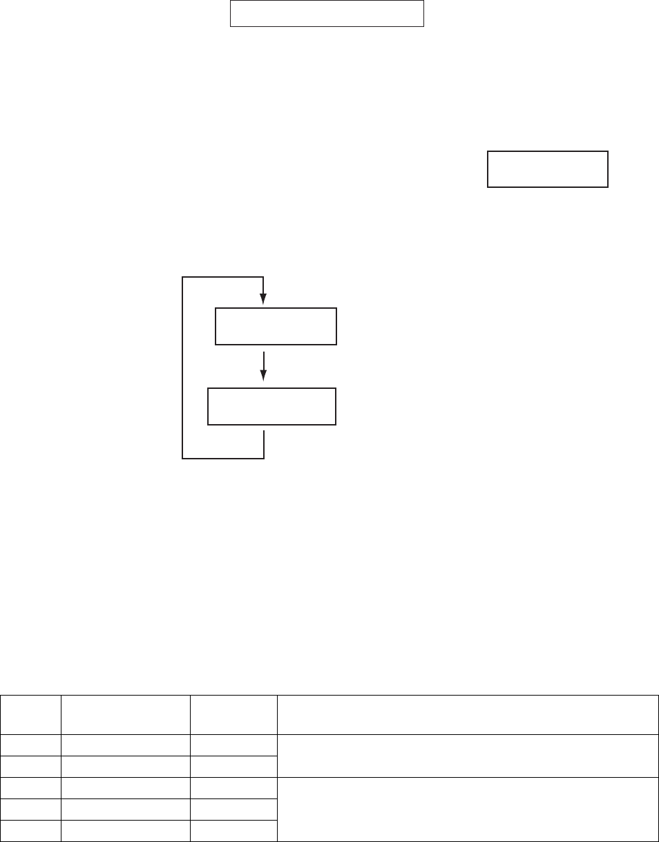
1. RADAR OPERATION
1-93
+ 34°40.849 N
135°18.303 E
CURSOR DATA
box (L/L position)
1.45.3 Selecting an antenna
For the ship that carries multiple antennas, you may choose the antenna to use
as follows:
1. Roll the trackball to place the arrow in the ANTENNA box at the left side of
the screen.
ANT1 X-BAND (M)
2. Roll the scrollwheel to choose an antenna then push the left button.
1.46 Cursor Data
Cursor data can be shown in latitude and longitude
position or cursor’s X-Y coordinates, with the C
specification radar.
Left-click the CURSOR DATA box at the right side of
the display to select the cursor data to show. The
cursor data changes in the sequence shown below.
+
34°30.323 N
135°08.263 E
+
9.649NM
9.683NM
Latitude and longitude
position of cursor
Cursor X-Y position
Cursor data options
Note 1: For the X-Y coordinates display, the Y-axis is the heading line, right/top
is "plus" and left/lower is "minus."
Note 2: When displaying latitude and longitude position and the cursor has been
aligned (on the PLOTTER menu), the indication "CHART ALIGN"
appears at the right side of the screen (in red).
Note 3: Cursor data reads "- - -.-" when the cursor is placed outside the effective
display area.
Note 4: Cursor bearing format (true or relative) and cursor range unit (nm, sm,
km or kyd) are available as below.
Type Cursor bearing
format
Cursor
range unit
Menu operation
IMO Yes No
A Yes No
2 [MARK]→9 EBL CURSOR BEARING
B Yes Yes
C Yes Yes
W Yes No
2 [MARK] →9 [EBL, VRM CURSOR SET] →CURSOR
BEARING, CURSOR RANGE

1. RADAR OPERATION
1-94
1.47 Performance Monitor
A performance monitor is required for a radar installed on vessels of 300 GT and
upward engaged in international voyages. Two units are available:
X-band radar: PM-31 (9410 ± 45 MHz)
S-band radar: PM-51 (3050 ± 30 MHz).
The performance monitor is incorporated in the antenna unit. When the
performance monitor is active, the indication "PM" appears (in yellow) in the
alarm box.
1.47.1 Activating, deactivating the performance monitor
1. Left-click the MENU box to open the menu.
2. Select 1 [ECHO] to open the ECHO menu.
[ECHO]
1 BACK
2 2ND ECHO REJ
OFF/ON
3 TUNE INITIALIZE
4 PM
OFF/ON
5 SART
OFF/ON
6 WIPER
OFF/1/2
7 ECHO AREA*
1
CIRCLE/WIDE/ALL
*1
Not available on IMO or A type
8 [PICTURE SELECT]
9 STC RANGE
+00
ECHO menu
3. Select 4 PM.
4. Select OFF or ON as appropriate.
5. Push the right button twice to close the menu.
"PM" appears on the display when the performance monitor is active.
1.47.2 Checking radar performance
1. The radar is automatically set up as follows:
Range: 24 nm
Pulselength: Long
Shadow Sector: Off
A/C SEA: Off
A/C RAIN: Off
Echo Stretch: Off
Echo Average: Off
Interference Rej.: Off
Video Contrast: 4-B
Tune: Auto
Gain: Initial setting (as set with PM GAIN ADJ at installation)
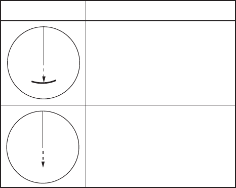
1. RADAR OPERATION
1-95
2. Turn on the performance monitor referring to section 1.47.1.
3. After observing the results turn off the performance monitor.
The range scale is automatically set to 24 nm. The radar screen will show one or
two arcs. If the radar transmitter and receiver are in good working conditions in
as much as the original state when the monitor was turned up, the innermost
arcs should appear between 13.5 to 18.5 nm. The performance monitor can
observe a total of 10 dB loss in transmitter and receiver.
Transmitter: normal
Receiver: normal
Transmitter and receiver:
No arc is indication of10 db
loss. Replacement of the
magnetron is necessary.
13.5 nm
to 18.5 nm
Display Radar State
13.5 nm
to 18.5 nm
Note: The lengths of the arcs may vary according to installation environment.
Judge the strength of the echo that appears within 90° behind own ship to
confirm if the radar is working properly or not.
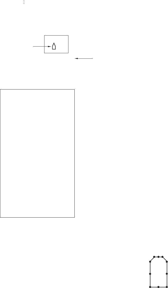
1. RADAR OPERATION
1-96
01
03
04
05
06
07
08
10
09
02
1.48 Own Ship Marker
Own ship marker ( ) may be inscribed on the screen as below. You may enter ten
such symbols. Each own ship symbols is shown with a number.
1. Use the trackball to select the MARK box at the left side of the screen. The
guidance box now reads "MARK SELECT / MARK MENU."
MARK
Mark type last
selected, mark
number
-> +
- - -m, - - -m
1
Dimensions of
own ship
Mark box
2. Push the right button to open the MARK menu.
[MARK MENU]
1 ORIGIN MARK STAB
GND/SEA
2 MARK KIND
ORIGIN MARK(No. )/
ORIGIN MARK(SYM)/
MAP MARK/
WP 1~50/
WP 51~ 100/
WP 101~150/
WP 151~198/
OWN SHIP SHAPE
8 MARK POSN
CURSOR/OS/L/L
00°000.00 N
000°000.00 E
9 MAP DISPLAY
OFF/ON
0 MAP MARK COLOR*
RED/GRN/BLU/YEL/
CYA/MAG/WHT
* Not available on IMO
or A type
MARK menu
3. Select "2".
4. Select OWN SHIP SHAPE. (On the W-type, the indication
"OS" appears to the right of the MARK box.)
5. Push the right button to close the menu.
6. Use the trackball to select the own ship symbol at the bottom
left corner.
7. Roll the scrollwheel to select the point number for which you
want to change its position. See figure at right.
8. Push the left button. The cursor positions at the point number
selected.
9. Use the trackball to drag the point to location desired.
10. Push the left button to confirm selected location.
11. Repeat steps 6-10 continue changing symbol shape.
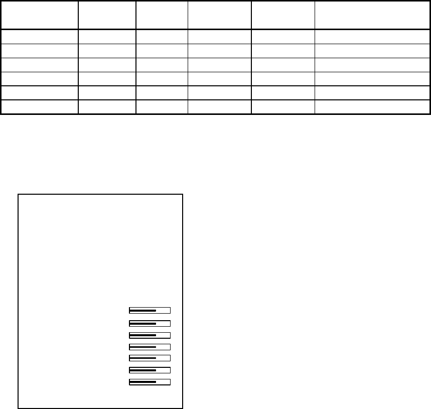
1. RADAR OPERATION
1-97
1.49 Color and Brilliance Sets
This radar provides six sets of color and brilliance sets to match any ambient
lighting condition.
1.49.1 Selecting color and brilliance set
Left-click the BRILL box at the left side of the screen to select color and brilliance
set from among BRILL1 – BRILL4. The default specifications of each brilliance
set are is in the table below.
PALETTE BRILL PANEL OTHERS
TEXT
COLOR BKGD/CIRCLE
DAY-GRY 100 15 15 GREEN GRY/BLK
DAY-BLU 100 15 15 WHITE BLU/BLU
DUSK-GRY 20 10 15 GREEN GRY/BLU
DUSK-BLU 20 10 15 WHITE BLU/BLU
NIGHT-GRY 4 5 15 RED GRY/BLK
NIGHT-BLU 4 5 15 WHITE BRT-BLU/BRT-BLU
1.49.2 Presetting color and brilliance set
1. Right-click the BRILL box at the left side of the screen to open the BRILL
menu.
* Not available on IMO or A type
[BRILL1 MENU (1/2)]
1 ECHO COLOR
YEL/GRN/
WHT/COLOR*
2 PALETTE
DAY-GRY/DAY-BLU/
DUSK-GRY/DUSK-BLU/
NIGHT-GRY/NIGHT-BLU/
3 PANEL DIMMER
4 CHARACTER
5 CURSOR
6 ECHO
7 TRAIL
8 HL
9 RING
0 NEXT
BRILL menu
2. Select 1 ECHO COLOR.
3. Select echo color desired. "COLOR," available on the B, C and W types,
displays echoes in colors of red, yellow and green, corresponding to signal
levels of strong, medium and weak.

1. RADAR OPERATION
1-98
4. Select 2 PALETTE.
5. Select desired time of day and background color combination.
PALETTE BRILL PANEL OTHERS
TEXT
COLOR BKGD/CIRCLE
DAY-GRY 100 15 15 GREEN GRY/BLK
DAY-BLU 100 15 15 WHITE BLU/BLU
DUSK-GRY 20 10 15 GREEN GRY/BLU
DUSK-BLU 20 10 15 WHITE BLU/BLU
NIGHT-GRY 4 5 15 RED GRY/BLK
NIGHT-BLU 4 5 15 WHITE BRT-BLU/BRT-BLU
6. Set brilliance-related items referring to section 1.39.
7. Push the right button to close the BRILL menu.
Note: The above default settings are restored whenever the setting for 2
PALETTE is changed.
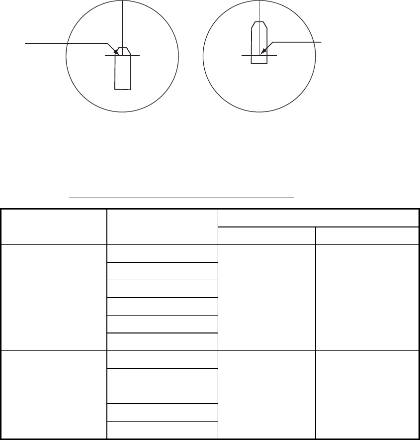
1. RADAR OPERATION
1-99
1.50 Reference Position
The reference position for measurements (range, bearing, etc.) and markers
(heading line, stern mark, etc.) can be antenna position or consistent common
reference point (CCRP), which is a location on own ship to which all horizontal
measurements, for example range, bearing, relative course, relative speed,
closest point of approach (CPA) or time to closest point of approach (TCPA), are
normally referenced.
To select reference position, right-click the REF POINT indication at the top of
the screen to select ANT or CCRP as applicable.
The position of the own ship marker changes according to reference position as
shown below. If the CCRP is positioned outside of the effective display area, the
bearing scale is indicated with the appropriate reduced detail.
X
CCRP position
X
ANT position
Radar antenna
position is at
center of display
Conning position is at
center of display
Range and bearing are measured and graphics are drawn according to
reference position as in the table below.
Markers, measurements and reference point
Reference point
Category Item CCRP Antenna position
EBL
VRM
Cursor
PI line
Range ring
Range and bearing
measurement
Drop mark
Range and
bearing
measured from
CCRP
Range and bearing
measured from
antenna position
Heading line
Stern mark
Beam line
Own ship vector
Graphics
Own ship track
Drawn from
CCRP
Drawn from
antenna position

1. RADAR OPERATION
1-100
Markers, measurements and reference point (con't)
Reference point
Category Item CCRP Antenna position
Bearing cursor Drawn with
CCRP at center
Drawn with
antenna position at
center
Course, speed Calculated with
CCRP at center
Calculated with
antenna position at
center
CPA, TCPA Calculated with
CCRP at center
Calculated with
antenna position at
center
BCR, BCT Calculated from bow position
Heading
Speed
Course over ground
Speed over ground
Own ship data
Own L/L
Data from sensor, regardless of
reference point selected
Note: When the antenna is located some distance from the CCRP, the CCRP
may be outside the bearing cursor in true motion or offcenter.
Also, when the CCRP is set as reference point, some parts of the bearing
cursor are not displayed.
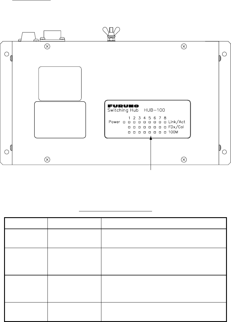
1. RADAR OPERATION
1-101
1.51 Switching Hub HUB-100 (option)
The HUB-100 provides switching for a card interface unit and multiple processor
units (max. 7), using an Ethernet interface (100BASE-TX/10BASE-T). LEDs
display link/activity, mode (full-duplex or half-duplex) and collision statuses.
No operation is required of the user. Simply turn on the HUB-100’s AC power
source to power it.
LED display
The LEDs on the top of the unit light, flash or go off according to equipment
status. When the equipment is powered all LEDs light then go off.
LEDs
Switching Hub HUB-100
LED status and meaning
LED Status Meaning
Power Lit
Off
Equipment powered
Equipment off
Link/Act Lit
Off
Flashing
Connection with terminal normal
Connection with terminal disconnected
Data TX or RX
FDx/Col Lit
Off
Flashing
Full-duplex
Half-duplex
Collision
100M Lit
Off
100Mbps connection
10Mbps connection
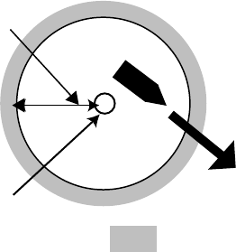
1. RADAR OPERATION
1-102
1.52 Anchor Watch
The anchor watch feature alerts you when your ship has traveled a distance
greater than a threshold value, when it should be at rest. When the anchor
watch is active, an orange dashed circle marks the anchor watch range. If your
ship goes outside the circle, "ANCHOR WATCH" appears in the Alert Box.
Your ship's position, where
you start the anchor watch.
Alarm
setting
: Alarm triggered
1. Left-click the MENU box to open the menu.
2. Select 2 [MARK].
3. Select 5 ANCHOR WATCH.
4. Select ON.
5. Roll the scrollwheel to set the alarm range, from 0-9.99 (nm).
6. Push the right button to close the menu.

1. RADAR OPERATION
1-103
1.53 Drop Mark
The operator inscribes a drop mark ( ) at a selected location to find the range
and bearing from own ship to the mark. This can be useful for marking a point to
avoid while navigating to a destination.
1.53.1 Activating the drop mark feature
1. Left-click the MENU box to open the menu.
2. Select 2 [MARK].
[MARK]
1 BACK
2 OWN SHIP MARK
OFF/MIN/SCALED
3 STERN MARK
OFF/ON
4 [PI LINE]
5 ANCHOR WATCH
OFF/ON
0.0NM
6 DROP MARK
OFF/ON
7 [INS MARK] *1
8 EBL OFFSET BASE
STAB GND/STAB HDG/
STAB NORTH
9 [EBL, VRM, CURSOR SET]*2
0 RING
OFF/ON
*
1
[BARGE MARK] depending on installation preset.
*
2
IMO and A types show
9 EBL CURSOR BEARING (REL/TRUE)
3. Select 6 DROP MARK.
4. Select ON. Two "DROP MARK" boxes appear at the bottom of the display.
(See the figure on the next page.)
5. Push the right button several times to close the menu.
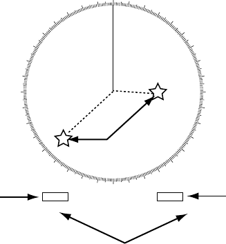
1. RADAR OPERATION
1-104
1.53.2 Inscribing a drop mark
1. Left-click one of the DROP MARK boxes at the bottom of the screen.
2. Put the cursor on the point you want to measure the range and bearing and
push the left button. A drop mark is inscribed on the screen and range and
bearing between own ship and the drop mark are shown below
corresponding DROP MARK box.
000 010 020
030
040
050
060
070
080
090
100
110
120
130
140
150
160
170
180
190
200
210
220
230
240
250
260
270
280
290
300
310
320
330 340 350
DROP1
229.8°T 4.532NM
DROP2
90.38°T 2.873NM
Drop
Mark
Range and bearing
to drop mark
No. 1 DROP
MARK box
No. 2 DROP
MARK box
1.53.3 Erasing a drop mark
Left-click the appropriate DROP MARK box until the drop mark and its data are
erased. (The DROP MARK box remains on the screen until the drop mark
feature is turned off from the menu.)

1. RADAR OPERATION
1-105
1.54 Sub Monitor (A, B, C and W types)
The picture from a radar outside the LAN network can be shown on this radar
(processor unit+display unit+control unit).
1. Put the cursor in the ANTENNA box at the upper left side of the screen.
2. Right-click to show the ANT SELECT menu.
[ANT SELECT]
ANT1: X-BAND
12 FORE
ANT2: X-BAND
12 MAIN TOP
ANT3: X-BAND
MAIN TOP
12
ANT4: X-BAND
AFT
OWN RADAR No.: 2
1 DISP1 ANT1
MASTER
2 DISP2 ANT2
MASTER
* Not available on IMO or A radar.
9 STORE INTER-SW
NO/YES
0 SUB MONITOR*
OFF/ON
3 DISP3 ANT3
MASTER
4 DISP4 ANT4
MASTER
12
3. Spin the scrollwheel to select 0 SUB MONITOR then push the left button.
4. Spin the scrollwheel to select ON then push the left button.
The antenna box shows "SUB" and the image from the sub monitor is shown
on this radar
5. Push the right button to close the menu.
Antenna-related functions of the sub monitor; for example, pulselength, cannot
be controlled from this radar.

1. RADAR OPERATION
1-106
1.55 Net Cursor
The net cursor is used to depict your fishing net on the radar display. It is
especially useful for bottom trawlers for knowing where the net is located. Enter
the dimensions of your net in the menu to show the net in scale on the display.
Net curso
r
EBL2
1.55.1 Activating the net cursor
1. Left-click the MENU box.
2. Select 2 [MARK] then push the left button.
3. Select 9 [EBL, VRM, CURSOR SET] then push the left button.
[EBL, VRM, CURSOR SET]
1 BACK
2 EBL1
REL/TRUE
3 EBL2
REL/TRUE
4 VRM1
NM/SM/km/kyd
5 VRM2
NM/SM/km/kyd
6 CURSOR BEARING
REL/TRUE
7 CURSOR RANGE
NM/SM/km/kyd
8 [ CURSOR SHAPE]
9 CURSOR BRG SCALE
360°/32 POINTS
4. Select 8 [CURSOR SHAPE] then push the left button.
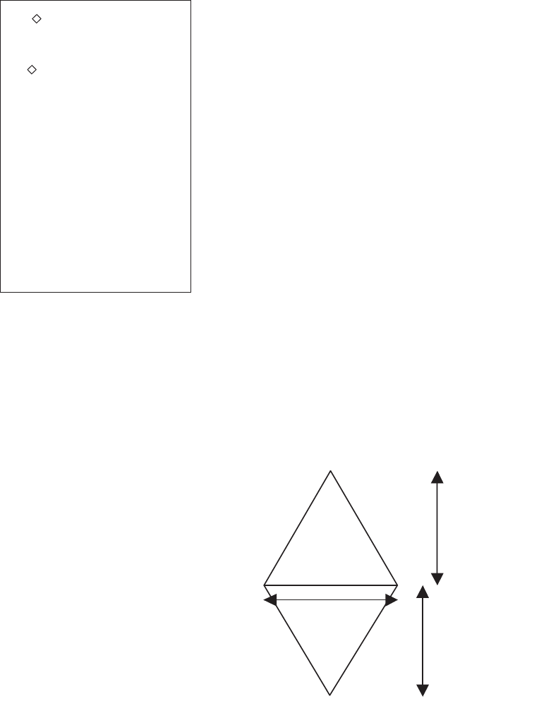
1. RADAR OPERATION
1-107
FRONT HALF
LENGTH
REAR HALF
LENGTH
NET WIDTH
a
b
[ CURSOR SHAPE]
1 BACK
2 CURSOR
OFF/ON
3 FRONT HALF LENGTH
0.0m
4 REAR HALF LENGTH
0.0m
5 NET WIDTH
0.0m
6 ROTATE STEP
360°/32 POINTS
WARP LENGTH
0.0m
5. Select 2 [CURSOR] then push the left button.
6. Select ON then push the left button to enable the net cursor. EBL2 is then
automatically turned on.
7. Push the right button four times to close the menu.
1.55.2 Setting net cursor dimensions, adjusting net cursor
orientation
1. Left-click the MENU box.
2. Select 2 [MARK] then push the
left button.
3. Select 9 [EBL, VRM, CURSOR
SET] then push the left button.
4. Select 8 [CURSOR SHAPE] then
push the left button.
5. Set net cursor dimensions as
follows, referring to the illustration
at right.
a) Select FRONT HALF LENGTH
then push the left button.
b) Spin the scrollwheel to set front half length (0-3000 m) then push the left
button.
c) Set REAR HALF LENGTH and NET WIDTH similarly.
d) Warp length (a+b in the illustration at right) is indicated at the bottom of the
menu. The net cursor is placed at the screen center, with its top and bottom
points bisected by EBL2. To adjust the position of the net cursor, go to step 6.
Otherwise, go to step 9.
6. Select 6 ROTATE STEP then push the left button.
7. Select 360° or 32 POINTS as appropriate then push the left button. These
figures determine how finely to rotate the EBL2 when adjusting the
orientation of the net cursor. Select 360° for fine rotation or 32 POINTS for
coarse rotation.
8. Use the rotary encoder for the EBL to adjust the orientation of the net cursor.
1. RADAR OPERATION
1-108
9. Push the right button four times to close the menu.
10. Use the EBL offset feature to anchor the net cursor at net origin point.
a) Push the EBL OFFSET key.
b) Use the trackball to set net origin point.
c) Push the EBL OFFSET key to anchor the net cursor.
11. Steer the vessel so your ship’s trail runs along the net cursor then throw the
net.

2-1
2. RADAR OBSERVATION
2.1 General
2.1.1 Minimum and maximum ranges
Minimum range
The minimum range is defined by the shortest distance at which, using a scale of
1.5 or 0.75 nm, a target having an echoing area of 10 m2 is still shown separate
from the point representing the antenna position.
It is mainly dependent on the pulselength, antenna height, and signal processing
such as main bang reduction and digital quantization. It is a good practice to use
a shorter range scale as far as it gives favorable definition or clarity of picture.
The IMO Resolution MSC.192(79) requires the minimum range to be less than
40 m, respectively. This series of radars satisfy this requirement.
Maximum range
The maximum detecting range of the radar, Rmax, varies considerably
depending on several factors such as the height of the antenna above the
waterline, the height of the target above the sea, the size, shape and material of
the target, and the atmospheric conditions.
Under normal atmospheric conditions, the maximum range is equal to the radar
horizon or a little shorter. The radar horizon is longer than the optical one by
about 6% because of the diffraction property of the radar signal. The Rmax is
given in the following equation.
R
max
= 2.2 x ( h1 +h2 )
where Rmax: radar horizon (nautical miles)
h1: antenna height (m)
h2 : target height (m)
Radar horizon
Optical horizon
For example, if the height of the antenna above the waterline is 9 meters and the
height of the target is 16 meters, the maximum radar range is;
R
max
= 2.2 x ( 9 + 16 ) = 2.2 x (3 + 4) = 15.4 nm
It should be noted that the detection range is reduced by precipitation (which
absorbs the radar signal).

2. RADAR OBSERVATION
2-2
X-band and S-band
In fair weather, the equation on the previous page does not give a significant
difference between X- and S-band radars. However, in heavy precipitation
condition, an S-band radar would have better detection than an X-band radar.
Radar resolution
There are two important factors in radar resolution (discrimination): bearing
resolution and range resolution.
Bearing resolution
Bearing resolution is the ability of the radar to display as separate pips the
echoes received from two targets that are at the same range and close together.
It is proportional to the antenna length and reciprocally proportional to the
wavelength. The length of the antenna radiator should be selected for a bearing
resolution better than 2.5° (IMO Resolution). This condition is normally satisfied
with a radiator of 1.2 m (4 ft) or longer in the X-band. The S-band radar requires
a radiator of about 12 feet (3.6 m) or longer.
Range resolution
Range resolution is the ability to display as separate pips the echoes received
from two targets that are on the same bearing and close to each other. This is
determined by pulselength only. Practically, a 0.08 microsecond pulse offers the
discrimination better than 40 m as do so with all FURUNO radars.
Test targets for determining the range and bearing resolution are radar reflectors
having an echoing area of 10 m2.
Bearing accuracy
One of the most important features of the radar is how accurately the bearing of
a target can be measured. The accuracy of bearing measurement basically
depends on the narrowness of the radar beam. However, the bearing is usually
taken relative to the ship’s heading, and thus, proper adjustment of the heading
line at installation is an important factor in ensuring bearing accuracy. To
minimize error when measuring the bearing of a target, put the target echo at the
extreme position on the screen by selecting a suitable range.
Range measurement
Measurement of the range to a target is also a very important function of the
radar. Generally, there are two means of measuring range: the fixed range rings
and the variable range marker (VRM). The fixed range rings appear on the
screen with a predetermined interval and provide a rough estimate of the range
to a target. The variable range marker’s diameter is increased or decreased so
that the marker touches the inner edge of the target, allowing the operator to
obtain more accurate range measurements.
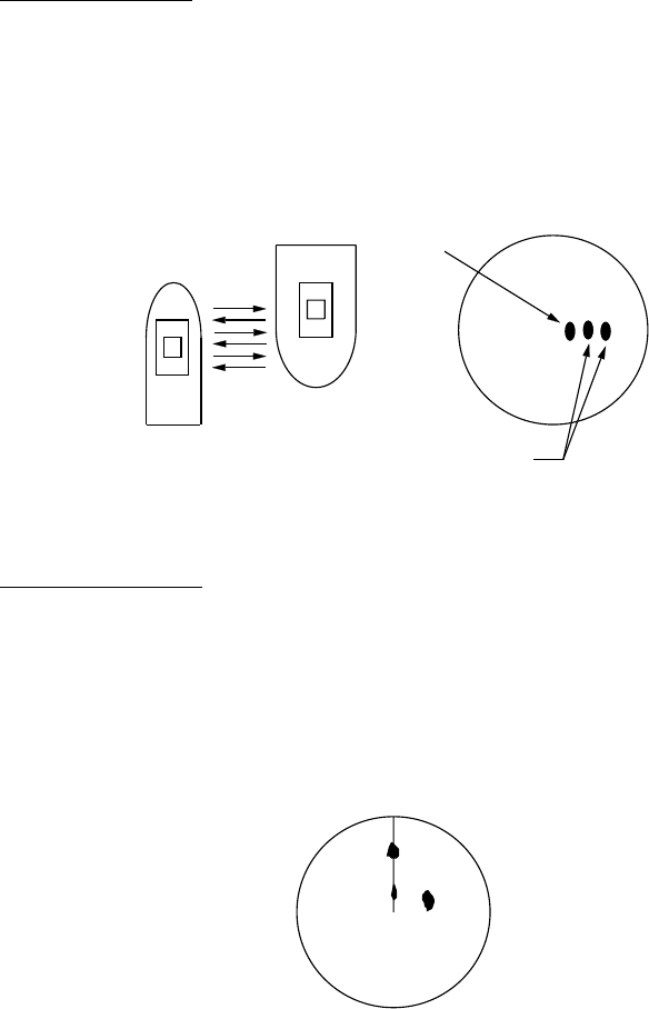
2. RADAR OBSERVATION
2-3
2.2 False Echoes
Occasionally echo signals appear on the screen at positions where there is no
target or disappear even if there are targets. They are, however, recognized if
you understand the reason why they are displayed. Typical false echoes are
shown below.
Multiple echoes
Multiple echoes occur when a transmitted pulse returns from a solid object like a
large ship, bridge, or breakwater. A second, a third or more echoes may be
observed on the display at double, triple or other multiples of the actual range of
the target as shown below. Multiple reflection echoes can be reduced and often
removed by decreasing the gain (sensitivity) or properly adjusting the A/C SEA
control.
Own ship
Target
Tr u e
echo
Multiple
echo
Multiple echoes
Sidelobe echoes
Every time the radar pulse is transmitted, some radiation escapes on each side
of the beam, called "sidelobes." If a target exists where it can be detected by the
side lobes as well as the main lobe, the side echoes may be represented on
both sides of the true echo at the same range. Side lobes show usually only on
short ranges and from strong targets. They can be reduced through careful
reduction of the gain or proper adjustment of the A/C SEA control.
Target B
(True)
Target B
(Spurious)
Target A
Sidelobe echoes
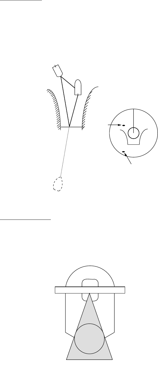
2. RADAR OBSERVATION
2-4
Virtual image
A relatively large target close to your ship may be represented at two positions
on the screen. One of them is the true echo directly reflected by the target and
the other is a false echo which is caused by the mirror effect of a large object on
or close to your ship as shown in the figure below. If your ship comes close to a
large metal bridge, for example, such a false echo may temporarily be seen on
the screen.
Tr u e
echo
False
echo
Own ship
Target ship
Mirror image
of target ship
Virtual image
Shadow sectors
Funnels, stacks, masts, or derricks in the path of the antenna block the radar
beam. If the angle subtended at the antenna is more than a few degrees, a
non-detecting sector may be produced. Within this sector targets can not be
detected.
Radar
antenna
Radar
mast
Shadow sector
Shadow sectors
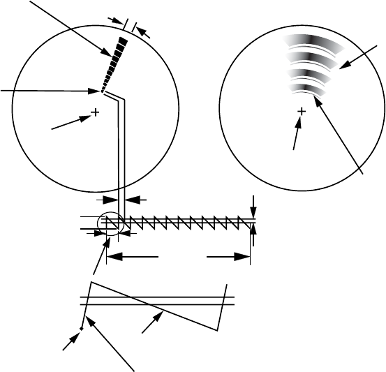
2. RADAR OBSERVATION
2-5
2.3 SART (Search and Rescue Transponder)
2.3.1 SART description
A Search and Rescue Transponder (SART) may be triggered by any X-Band (3
cm) radar within a range of approximately 8 nm. Each radar pulse received
causes it to transmit a response which is swept repetitively across the complete
radar frequency band. When interrogated, it first sweeps rapidly (0.4 µs) through
the band before beginning a relatively slow sweep (7.5 µs) through the band
back to the starting frequency. This process is repeated for a total of twelve
complete cycles. At some point in each sweep, the SART frequency will match
that of the interrogating radar and be within the pass band of the radar receiver.
If the SART is within range, the frequency match during each of the 12 slow
sweeps will produce a response on the radar display, thus a line of 12 dots
equally spaced by about 0.64 nautical miles will be shown.
When the radar to the SART is reduced to about 1 nm, the radar display my
show also the 12 responses generated during the fast sweeps. These additional
dot responses, which also are equally spaced by 0.64 nautical miles, will be
interspersed with the original line of 12 dots. They will appear slightly weaker
and smaller than the original dots.
9500 MHz
9200 MHz
Radar antenna
beamwidth
Screen A: When SART
is distant
Screen B: When SART
is close
Lines of 12 dots
are displayed in
concentric arcs.
Echo from SART
Position of
SART
Own ship
position Own ship
position
SART mark
length
Radar receiver
bandwidth
Sweep time
7.5 μs 95 μs
Sweep start
High speed sweep signal
Low speed sweep signal
24 NM 1.5 NM
Position of
SART
Echo from
SART
SART

2. RADAR OBSERVATION
2-6
2.3.2 Showing SART marks on the radar display
This radar is equipped with a feature that optimally sets up the radar for SART
detection. This feature automatically detunes the radar receiver out of its best
tuning condition. This erases or weakens all normal radar echoes, but the SART
marks are not erased because the SART response signal scans over all
frequencies in the 9 GHz band. When the radar approaches the SART in
operation, the SART marks will enlarge to large arcs, blurring a large part of the
screen.
To set up for SART detection do the following:
1. Left-click the MENU box to open the menu.
2. Select 1 [ECHO].
[ECHO]
1 BACK
2 2ND ECHO REJ
OFF/ON
3 TUNE INITIALIZE
4 PM
OFF/ON
5 SART
OFF/ON
6 WIPER
OFF/1/2
7 ECHO AREA*
1
CIRCLE/WIDE/ALL
*
1
Not available on IMO or A type
8 [PICTURE SELECT]
9 STC RANGE
+00
ECHO menu
3. Select 5 SART.
4. Select ON.
With SART turned on radar functions are set as follows:
Range: 12 nm
Pulselength: Long
Echo Stretch: Off
Noise Rejector: Off
Echo Averaging: Off
Interference Rejector: Off
Performance Monitor: Off
A/C RAIN: Off
5. Push the right button twice to close the menu.
"SART" appears at the bottom of the display when this feature is active. Be sure
to turn off the SART feature when SART detection is no longer your objective.

2. RADAR OBSERVATION
2-7
2.3.3 General remarks on receiving SARTs
SART range errors
When responses from only the 12 low frequency sweeps are visible (when the
SART is at a range greater than about 1 nm), the position at which the first dot is
displayed may be as much as 0.64 nm beyond the true position of the SART.
When the range closes so that the fast sweep responses are seen also, the first
of these will be no more than 150 meters beyond the true position.
Radar bandwidth
This is normally matched to the radar pulselength and is usually switched with
the range scale and the associated pulselength. Narrow bandwidths of 3-5 MHz
are used with long pulses on long range scales and wide bandwidths of 10-25
MHz with short pulses on short ranges.
A radar bandwidth of less than 5 MHz will attenuate the SART signal slightly, so
it is preferable to use a medium bandwidth to ensure optimum detection of the
SART.
Radar side lobes
As the SART is approached, side lobes from the radar antenna may show the
SART responses as a series of arcs or concentric rings. These can be removed
by the use of the anti-clutter sea control although it may be operationally useful
to observe the side lobes as they may be easier to detect in clutter conditions
and also they will confirm that the SART is near to own ship.
Note: SART information excerpted from IMO SN/Circ 197 OPERATION OF
MARINE RADAR FOR SART DETECTION.
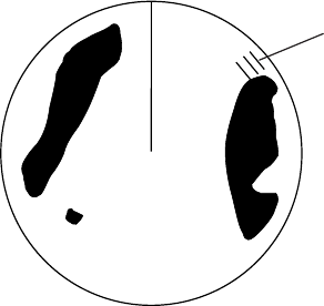
2. RADAR OBSERVATION
2-8
2.4 RACON
A RACON is a radar beacon that emits radar receivable signals in the radar
frequency spectrum (X- or S-band). There are several signal formats; in general,
the RACON signal appears on the radar screen as a rectangular echo
originating at a point just beyond the position of the radar beacon. It has a Morse
coded pattern. Note that the position on the radar display is not accurate.
RACON
RACON
2.5 Radar Target Enhancer (RTE)
An RTE is a radar transponder is mounted on navigation buoys and masts of
small crafts to significantly improve their detection by radar. Unlike a SART or
RACON, which are passive, the RTE receives a radar signal, amplifies it and
re-transmits it, with the intention of making the target's signal look larger on a
radar display. The RTE is available in X-band and S-band types.
3-1
3. TARGET TRACKING (TT)
3.1 Usage Precautions
WARNING
No one navigational aid should be relied
upon for the safety of vessel and crew.
The navigator has the responsibility to
check all aids available to confirm
position. Electronic aids are not
a substitute for basic navigational
principles and common sense.
• This TT automatically tracks
automatically or manually acquired radar
targets and calculates their courses and
speeds, indicating them by vectors. Since
the data generated by the auto plotter
are based on what radar targets are
selected, the radar must always be
optimally tuned for use with the auto
plotter, to ensure required targets will not
be lost or unwanted targets such as sea
returns and noise will not be acquired
and tracked.
• A target does not always mean a land-
mass, reef, ships or other surface vessels
but can imply returns from sea surface
and clutter. As the level of clutter changes
with environment, the operator should
properly adjust the A/C SEA, A/C RAIN
and GAIN controls to be sure target
echoes are not eliminated from the
radar screen.
CAUTION
The plotting accuracy and response of
this TT meets IMO standards.
Tracking accuracy is affected by the
following:
• Tracking accuracy is affected by course
change. One to two minutes is required to
restore vectors to full accuracy after an
abrupt course change. (The actual
amount depends on gyrocompass
specifications.)
• The amount of tracking delay is inversely
proportional to the relative speed of the
target. Delay is on the order of 15—30
seconds for high relative speed; 30—60
seconds for low relative speed.
• Display accuracy is affected by the
following:
- Echo intensity
- Radar transmission pulsewidth
- Radar bearing error
- Gyrocompass error
- Course change (own ship and target)
The data generated by TT, AIS and
video plotter are intended for
reference only.
Refer to official nautical charts for
detailed and up-to-date information.
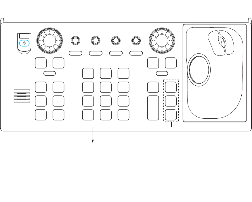
3. TARGET TRACKING (TT)
3-2
3.2 Controls for TT
Keyboard
The TT uses the keys shown below.
ACQ
ON
MENU
OFF
VRM
A/C SEAA/C RAIN
MODE
3
LINE
INDEX
6
OFF
21
HL
CENTER
OFF
45
RESET
CU/TM
OFFSET
EBL
GAIN
TARGET
CANCEL
TARGET
DATA
RANGE
-
+
LIST
TARGET
9
MARK
ENTER
TIME
VECTOR
78
CANCEL
TRAILS
0
MODE
VECTOR
BRILL
BRILL
EBL
F1
OFF
F2
ON
ACK
ALARM
F3 F4
STBY
TX
ACQ: Manually acquires a target.
TARGET DATA: Displays data on tracked target
chosen with the trackball.
TARGET CANCEL: Terminates tracking of tracked
target chosen with the trackball.
Control unit RCU-014
Trackball
With the cursor inside the effective display area, you can access TT functions by
rolling the scrollwheel or choosing appropriate TT function from the CURSOR
menu.
Roll the scrollwheel to show the following indications in the guidance box to
access respective TT function:
TT TARGET DATA & ACQ: Manually acquires a target, or displays data of the
cursor-selected tracked target.
TARGET CANCEL: Cancels tracking on cursor-selected tracked
target.

3. TARGET TRACKING (TT)
3-3
3.3 Activating, Deactivating TT
To activate or deactivate the TT:
Left-click the arrow in the TT ACQ MODE box at the right side of the display to
show OFF, MAN, AUTO or AUTO MAN as appropriate
TT
AUTO
MAN
TT ACQ MODE box
3.4 Entering Own Ship's Speed
The TT requires own ship's speed and heading data. The speed can be STW,
SOG or echo-referenced speed (based on 3 max. stationary objects). Manual
input is also possible.
For automatic or manual input, see section 1.13. For echo-referenced speed
input follow the procedure below.
3.4.1 Echo-referenced speed input
The use of echo-referenced speed is recommended when:
• The speed log is not operating properly or not connected to the radar.
• The vessel has no device (doppler sonar, speed log, etc.) that can measure
ship's bow-stern, port-starboard movement.
If you select echo-referenced speed, the TT calculates own ship's speed relative
to a fixed reference target. The number of targets may be R1, R2 or R3. When a
plural of objects are selected, the mean value is used, for stabilization and
speed.
1. With the cursor inside the effective display area, roll the scrollwheel to
display "REF MARK / EXIT" in the guidance box.
2. Select a small fixed island or any radar prominent point located at 0.2 to 24
nm from own ship.

3. TARGET TRACKING (TT)
3-4
3. Push the left button to enter the reference mark.
The reference target mark (see below) appears at the cursor position and
the own ship position data label changes from "LOG," "NAV" or "MANUAL" to
"REF." Note that it takes three minutes before a new speed is displayed. If
tracking has failed for a reference target, the target is marked with a lost
target mark (symbol formed with two triangles).
changes to in three minutes
R1 R1
Reference target
4. Repeat steps 2-3 to continue entering reference marks. Three may be
entered.
Notes on speed input by reference target
• Reference targets are only used for the calculation of true speed.
• Do not use reference target generated true speed to calculate relative speed.
Relative speed data is not accurate because response to speed change is
slow, hampering the TT's ability to accurately judge the possibility of collision.
• Select a stationary target as a reference target to calculate own ship speed as
ground tracking speed. Do not choose a moving target as a reference target. A
moving target produces error in the vector for TT and AIS, which results in
wrong collision avoidance information. Further, an unstable stationary target
produces inaccurate speed data and the target itself may become lost.
• When a reference target is lost or goes out of the acquisition range, that
reference target mark blinks and the indication "REF TARGET LOST" appears
in the alarm box. If all reference targets are lost, the speed indication reads
"*.*" Select a different reference target if currently selected one is lost.
• When all targets are deleted, the reference target mark is also deleted and the
target-based speed becomes invalid. The speed is indicated as BTREF where
BT means Bottom Track (speed over ground).
• Reference targets may be marked with a vector. This can be done with 3 REF
TARGET VECTOR on the TT TARGET menu.
• Loss of reference target will affect the calculation of true speed and true
course of targets. Further, own ship speed will be inaccurate.
Canceling echo-referenced speed input
Open the SPD menu, referring to section 1.13, and set 1 SHIP SPEED to LOG,
NAV or MANUAL as appropriate.

3. TARGET TRACKING (TT)
3-5
[TT TARGET MENU]
1 TT SELECT
MANUAL100/
AUTO 25/
AUTO 50/
AUTO 75/
AUTO 100
2 ALL CANCEL
NO/YES
3 REF TARGET VECTOR
OFF/ON
3.5 Automatic Acquisition
The FAR-2xx7 radars can acquire a maximum of 100 targets, the number of
automatically and manually acquired targets determined by the TT TARGET
menu setting.
TT TARGET setting and target acquisition condition
Menu Setting Acquisition condition
MANUAL100 100 targets manually
AUTO25 25 targets automatically, 75 targets manually
AUTO50 50 targets automatically, 50 targets manually
AUTO75 75 targets automatically, 25 targets manually
AUTO100 100 targets automatically
A target just acquired automatically is marked with a broken square and a vector
appears within one minute to indicate the target's motion trend. Within three
minutes, the initial tracking stage is finished and the target becomes ready for
stable tracking. At this point, the broken square mark changes to a solid circle.
(Targets automatically acquired are distinguished from those acquired manually.
The targets which are acquired manually are displayed with a thicker line.)
3.5.1 Enabling auto acquisition
1. Right-click the arrow in the TT ACQ MODE box to show the TT TARGET
menu.
TT TARGET menu
2. Select 1 TT SELECT.
3. Select automatic acquisition condition desired, referring to the table above for
details.
4. Push the right button to close the menu.
Note 1: The TT ACQ MODE box shows AUTO when the automatic acquisition
condition is selected.
Note 2: When the menu-set number of automatically acquired targets is
reached, the message "TARGET-FULL (AUTO)" is displayed at the
right-hand side of screen.

3. TARGET TRACKING (TT)
3-6
[TT TARGET MENU]
1 TT SELECT
MANUAL100/
AUTO 25/
AUTO 50/
AUTO 75/
AUTO 100
3 ALL CANCEL
NO/YES
3 REF TARGET VECTOR
OFF/ON
3.5.2 Terminating tracking of targets (including reference targets)
When the TT has acquired the menu-set number of targets automatically, the
message "TARGET-FULL(AUTO)(or MAN)" appears at the right side of the
screen and no more auto acquisition occurs unless targets are lost. Should this
happen, cancel tracking of less important targets or perform manual acquisition.
Canceling individual targets
By keyboard:
1. Use the trackball to put the cursor (+) on the tracked target, reference target
or lost target you wish to cancel tracking.
2. Press the [TARGET CANCEL] key.
By trackball:
1. With the cursor inside the effective display area, roll the scrollwheel to show
TARGET CANCEL / EXIT in the guidance box.
2. Put the cursor (+) on the tracked target, reference target or lost target you
wish to cancel tracking.
3. Push the left button to cancel tracking on the target selected.
4. To finish, push the right button.
Canceling tracking on all targets
1. Right-click the TT ACQ MODE box at the right side of the screen to show the
TT TARGET menu.
TT TARGET menu
2. Select 2 ALL CANCEL and YES.
3. Push the left button to cancel tracking on all tracked targets.

3. TARGET TRACKING (TT)
3-7
[TT TARGET MENU]
1 TT SELECT
MANUAL100/
AUTO 25/
AUTO 50/
AUTO 75/
AUTO 100
4 ALL CANCEL
NO/YES
3 REF TARGET VECTOR
OFF/ON
3.6 Manual Acquisition
Maximum 100 targets may be acquired manually depending on the acquisition
condition set on the TT TGT menu.
3.6.1 Setting manual acquisition conditions
1. Right-click the arrow in the TT ACQ MODE box at the right side to show the
TT TARGET menu.
TT TARGET menu
2. Select 1 TT SELECT.
3. Select MANUAL 100, AUTO 25, AUTO 50 or AUTO 75 as appropriate. For
details see the table on page 3-5.
4. Push the right button to close the menu.
3.6.2 Manually acquiring targets
By keyboard
1. Put the cursor on the target you want to acquire.
2. Press the [ACQ] key.
By trackball
1. With the cursor inside the effective display area, roll the scrollwheel to show
"TT TARGET DATA & ACQ" in the guidance box.
2. Put the cursor on the target you want to acquire.
3. Push the left button to acquire the target.
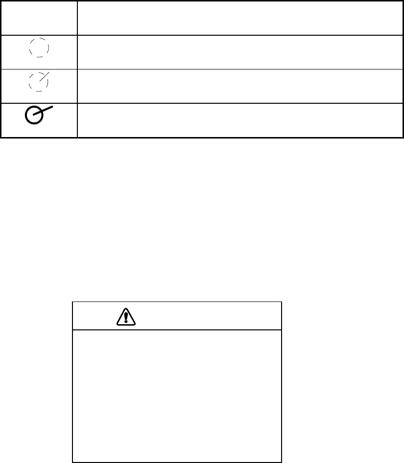
3. TARGET TRACKING (TT)
3-8
The plotting symbol is drawn by broken lines during the initial acquisition stage.
A vector appears in about one minute after acquisition indicating the target's
motion trend. If the target is consistently detected for three minutes, the plotting
symbol changes to a solid circle. If acquisition fails, the target plotting symbol
blinks and disappears shortly.
TT
Symbol Meaning
Immediately after acquisition, this plotting symbol is shown in
broken lines.
Within one minute after acquisition, a vector appears to show a
trend of movement.
Within three minutes after acquisition, the plotting symbol changes
to a small circle, indicating steady-state tracking condition.
Note 1: For successful acquisition, the target to be acquired should be within 0.1
to 24 nm (or 32 nm, depending on initial setting) from own ship and not
obscured by sea or rain clutter.
Note 2: When the capacity for manual acquisition is reached, the message
"TARGET FULL(MAN)" is displayed at the screen bottom. Cancel
tracking of non-threatening targets if you wish to acquire additional
targets manually.
Note 3: Target number is normally not shown. On the A, B, C and W type radars
it appears when the cursor is placed on a TT symbol.
CAUTION
Target Swap
When a target being tracked nears another
target being tracked, the targets may be
"swapped". When two targets acquired
either automatically or manually come close
to each other, one of the two may become
a Lost Target. Should this happen, manual
re-acquisition of the Lost Target may be
required after the two have separated.

3. TARGET TRACKING (TT)
3-9
[TT LOST ALM FILTER]
1 BACK
2 MAX RANGE
OFF/ON
0NM
3 MIN SHIP SPEED
OFF/ON
0.0kn
3.7 Lost Target
Targets not detected in five consecutive scans become "lost targets." A lost
target is shown in the display with flashing red "X". Flashing stops after lost
target alarm is acknowledged.
If you are in an area where tracked targets are lost frequently you may want to
disable the lost target alarm against tracked targets by maximum range or
minimum speed.
3.7.1 Setting the lost target filter
You can set the lost target alarm to sound against lost TTs that are within a
specific range or ship speed. Set the criteria as below.
1. Left-click the MENU box to open the menu.
2. Select 4 [TT.AIS] to open the TT.AIS menu.
3. Select 9 [TT LOST FILTER].
4. Set items 2 and 3 as appropriate, referring to the description below.
MAX RANGE: Any TT lost targets beyond this range will not trigger the
lost target alarm.
MIN SHIP SPEED: Any TT lost targets slower than this setting will not trigger
the lost target alarm.
5. Push the right button several times to close the menu.
Note: Reference targets are not affected by this filter.
3.7.2 Enabling, disabling the lost target alarm
The LOST TARGET ALARM box at the bottom right corner enables and disables
the lost target alarm. Select OFF, ALL or FILT as appropriate.
OFF: Disable the alarm
ALL: Get the alarm against all lost targets.
FILT: Get the alarm against the targets whose
criteria meet the settings on the TT LOST
ALM FILTER menu.
LOST TARGET ALAEM OFF
LOST TARGET box
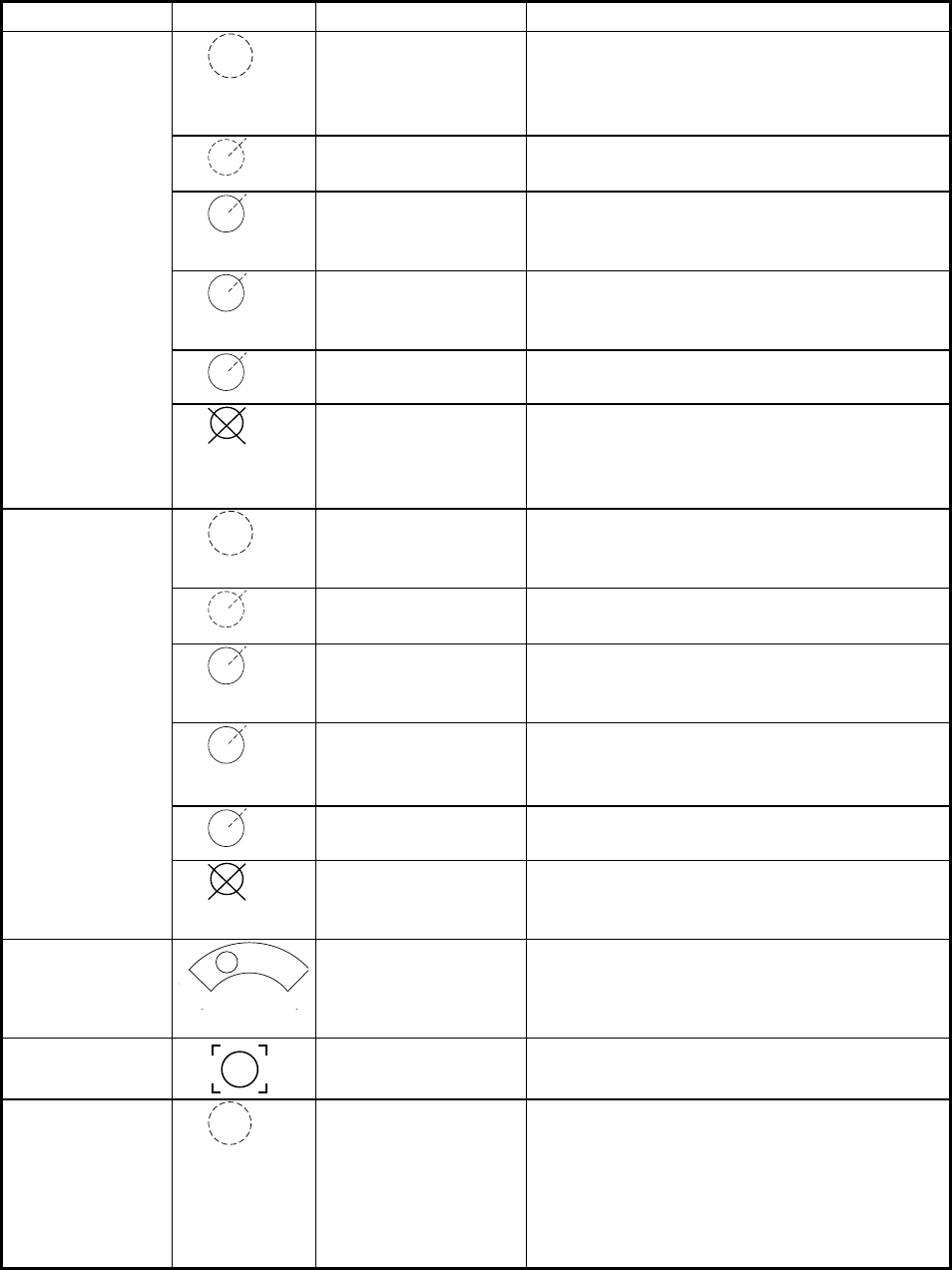
3. TARGET TRACKING (TT)
3-10
3.8 TT Symbols and Attributes
3.8.1 TT symbols
The symbols used in this equipment comply with IEC 62288.
Item Symbol Status Remarks
Initial stage
Broken circle around an echo to indicate
the target under acquisition and initial
stage of tracking, before steady-state
tracking.
Within one minute after acquisition (vector
still unreliable).
Steady tracking
Solid circle with vector indicating steady
state tracking (within three minutes after
acquisition).
(flashing)
CPA alarm Plotting symbol (red) flashes to indicate
the target is predicted to come into CPA or
TCPA.
CPA alarm
acknowledge
Shown in red, and flashing stops after
CPA/TCPA alarm is acknowledged.
Automatically
acquired targets
(flashing)
Lost target A red X is crossed through the TT symbol
to indicate that it is a lost target. Flashing
stops after lost target alarm is acknow-
ledged.
Initial stage
Plotting symbol selected for a target
acquired manually is shown in bold broken
lines.
Within one minute after acquisition.
Steady tracking Manual plotting symbol in a bold solid
circle (within three minutes after
acquisition).
(flashing)
CPA alarm
(collision course)
Plotting symbol (red) flashes to indicate
the target is predicted to come into CPA or
TCPA.
Flashing stops after CPA/TCPA alarm is
acknowledged.
Manually
acquired targets
(the width of the
line for "steady
tracking" TT is
thicker than that
of the auto-
matically
acquired target)
(flashing)
Lost target A red X is superimposed on the TT symbol
to indicate a lost target. Flashing stops
after lost target alarm is acknowledged.
Acquisition zone
(flashing)
On target passing
through operator-set
acquisition zone
Symbol is red and flashing.
Target selected
for data readout
On selected target Target data (range, bearing, course,
speed, CPA, TCPA, BCR, BCT, etc.).
Reference target
R
After three
minutes,
changes to
○R
On reference target Used to calculate own ship’s
over-the-ground speed (echo-referenced
speed) for ground stabilization.
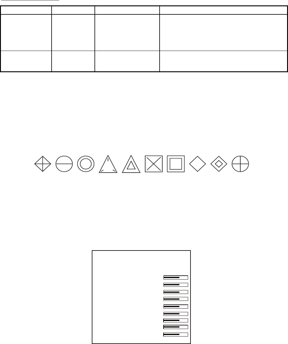
3. TARGET TRACKING (TT)
3
-
11
Other TT symbols
Item Symbol Status Remarks
Trial maneuver T
(flashing)
Bottom center
Appears during execution of a trial
maneuver.
Performance
test
S
(flashing)
Bottom center Appears during performance test.
3.8.2 Choosing TT symbol (B, C and W types)
In addition to the "standard" circle TT symbol, you may select from the symbols
shown below, using the full keyboard. This cannot be done with trackball-type
control unit (RCU-015, RCU-016). However, you can program a function key to do
so, with the combination of the "STD KEY" category and the option "TARGET
DATA."
1. Put the cursor on the TT symbol you want to change.
2. Press the [TARGET DATA] key.
3. Press the [TARGET DATA] key until desired symbol is displayed.
3.8.3 TT symbol brilliance
1. Right-click the BRILL box at the left side of the screen.
2. Select 0 NEXT.
[BRILL1 MENU (2/2)]
1 BACK
2 BRG CURSOR
3 EBL
4 VRM
5 PI LINE
6 TT SYMBOL
7 AIS SYMBOL
8 L/L GRID
9 MARK
0 CHART
BRILL menu, page 2
3. Select 6 TT SYMBOL.
4. Roll the scrollwheel to adjust brilliance.
5. Push the right button twice to close the menu.

3. TARGET TRACKING (TT)
3-12
[TT•AIS]
1 BACK
2 AZ STAB
STAB HDG/STAB NORTH
3 AZ POLYGON
OFF/STAB GND/
STAB HDG/STAB NORTH
4 [TRIAL MANEUVER]
5 [TT•AIS SYMBOL]
6 [CPA AUTO ACTIVATE]
7 [AIS DISP FILTER]
8 [AIS LOST FILTER]
9 [TT LOST FILTER]
0 [ASSOCIATION]
[TT•AIS SYMBOL]
1 BACK
2 TT•AIS SYMBOL COLOR
RED*/GRN/BLU/YEL*/
CYA/MAG/WHT
3 AIS ROT TAG LIMIT
0.000°/MIN
4 TT PAST POSN POINTS
5/10
5 AIS PAST POSN POINTS
5/10
6 AIS SCALED SYMBOL
OFF/ON
3.8.4 TT symbol color
You may select the color for the TT symbol as follows:
1. Left-click the MENU box to open the menu.
2. Select 4 [TT•AIS] to open the TT.AIS menu.
TT•AIS menu
3. Select 5 [TT•AIS SYMBOL].
* Not available on
IMO type

3. TARGET TRACKING (TT)
3-13
3.9 Displaying Target Data
The TT mode provides the full functionality of TT as required by the IMO
Resolution A.823(19) and IEC 62288, including display of range, bearing, course,
speed, CPA and TCPA of all tracked targets.
The target bearing is show in relative bearing in the head-up mode and true
bearing in the course-up, north-up and true motion modes, with the suffix "R"
(Relative) or "T" (True).
The target speed and course are shown as speed over the ground or speed
through the water depending on speed source.
3.9.1 Displaying target data
By keyboard
Use the trackball to put the cursor on a desired tracked target and press the
[TARGET DATA] key. The target’s shape changes to a square. To erase a
target’s data from the data box, press the key again.
By trackball
1. With cursor inside the effective display area, roll the scrollwheel to show
"TARGET DATA & ACQ / CURSOR MENU" in the guidance box.
2. Use the trackball to put the cursor on a desired tracked target then push the
left button.
3. To erase a target’s data from the data box, select the target on the radar
display then push the left button.
Target data display is as below.
RNG/BRG: Range and bearing from own ship to the selected target with suffix
"T" (True) or "R" (Relative).
COG/SOG (in case of GPS): Course and speed are displayed for the selected
target with suffix "T" (True) or "R" (relative). CSE/STW are shown for manual
speed and speed through the water.
CPA/TCPA: CPA (Closest Point of Approach) is the closest range a target will
approach to own ship. TCPA is the time to CPA. Both CPA and TCPA are
automatically calculated. When the CPA has passed clear of own ship, it is
indicated by a TCPA with a negative (-) sign. TCPA is counted to 99.9 min and
beyond this, it is indicate as TCPA> -99.9MIN.
BCR/BCT: BCR is the closest range at which the selected target is predicted to
cross your ship’s bow. BCT is the time at which the selected target is predicted
to cross your ship’s bow.
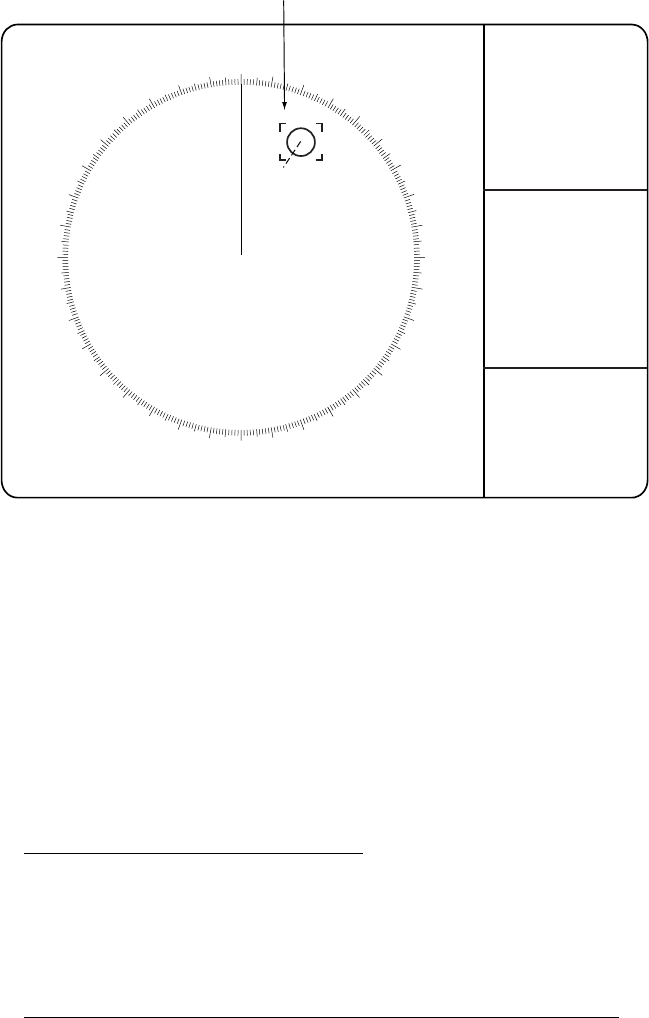
3. TARGET TRACKING (TT)
3-14
000 010 020
030
040
050
060
070
080
090
100
110
120
130
140
150
160
170
180
190
200
210
220
230
240
250
260
270
280
290
300
310
320
330 340 350
Target selected for data readout
TT TARGET
No. 01
BRG 25.5°T
RNG 3.4NM
T COG 205.1°T*
T SOG 12.3KN*
CPA 2.9NM
TCPA 12.2MIN
BCR 1.7NM
BCT 20MIN
01
BRG: Bearing from own ship to target
in R (Relative) or T (True)
RNG: Range from own ship to target
COG: Course of target over ground, True or Relative*
SOG: Speed of target over ground*
CPA: Closest Point of Approach of target to own ship
TCPA: Time to CPA
BCR: Bow crossing range of target
BCT: Bow crossing time of target
* CSE and STW are shown
in case of manual speed,
speed through the water.
Tracked target display
You may display the target data for two targets in one data box and the data for
as many as six targets can be displayed. For further details, see section 1.42.
Removing a target data display
Full keyboard: Put the cursor on the data you want to remove then hit the
[TARGET DATA] key.
Cursor menu: TARGET DATA & ACQ
Canceling tracking on a target from target data display
Full keyboard: Put the cursor on the data you want to remove then hit the
[TARGET CANCEL] key.
Cursor menu: TARGET CANCEL

3. TARGET TRACKING (TT)
3-15
[TARGET LIST (1/1)]
SORT BY CPA
1 BACK
2 TT TARGET
No: 01
BRG 16.5°T RNG 2.05 NM
CPA 0.17NM TCPA>99.59M
3 TT TARGET
No: 02
BRG 19.0°T RNG 2.49 NM
CPA 0.29NM TCPA>99.59M
9 REFRESH DATA
3.9.2 Target list
The target list provides a comprehensive data display of all TT (and AIS) targets
being tracked.
Displaying the target list
To display the target list, do the following:
1. Select the TARGET LIST box at the right side of the screen.
TARGET
LIST
TARGET LIST box
2. Push the left button to display the TARGET LIST. ">" in the TCPA means that
the time is greater than 99:59.
Target list
3. To scroll the list when there are more than three targets, select 0 NEXT.
Note: To refresh data, select 9 REFRESH DATA then push the scrollwheel.
This is not necessary when the sorting method is changed (see next
page); data is automatically updated whenever the sorting method is
changed.
4. Push the right button to close the list.

3. TARGET TRACKING (TT)
3-16
[TARGET LIST MENU]
1 SORT BY
CPA/TCPA/BCR/BCT/
RANGE/SPEED
Sorting the target list
You may sort the target list by CPA, TCPA, BCR, BCT, RANGE or SPEED as
follows: 72 nm or 96 nm range scale
1. Right-click the TARGET LIST box.
TARGET LIST menu
2. Select 1 SORT BY.
3. Select sorting method desired.
4. Push the right button to close the menu.
3.10 Vector Modes
Target vectors can be displayed relative to own ship's heading (Relative) or north
(True).
3.10.1 Description of vectors
Ground stabilization and sea stabilization
Target vectors can be ground stabilized or sea stabilized. You can select ground
or sea stabilization from the SPEED menu. Select BT(Bottom Tracking) for
ground stabilization or WT(Water Tracking) for sea stabilization. The TT
VECTOR box shows the stabilization mode as TRUE-G or TRUE-S.
Sea stabilization is a mode where own ship and all targets are referenced to the
sea using a compass heading and single-axis log water speed inputs. Ground
stabilization is a mode where own ship and all targets are referenced to the
ground using the ground track or set and drift inputs. If the accuracy seems
unsatisfactory, enter set and drift corrections. Note that set and drift cannot be
used on the IMO radar when the radar is displaying AIS targets.
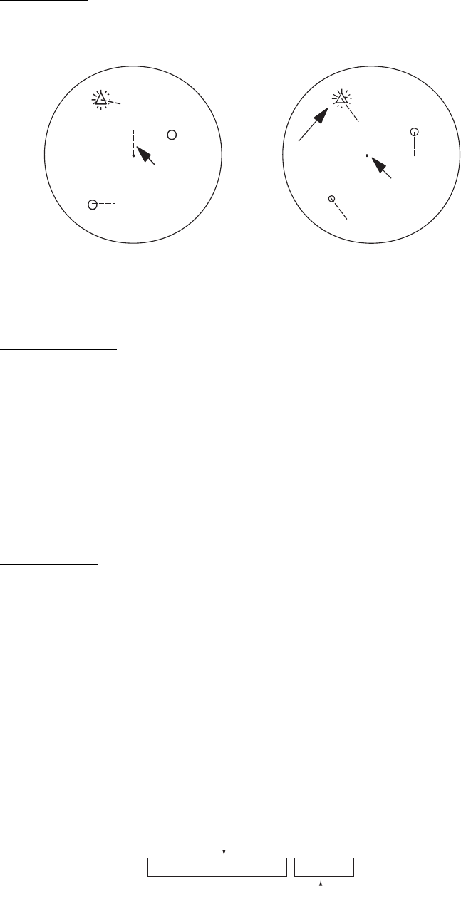
3. TARGET TRACKING (TT)
3-17
True vector
Own ship and other ship's move on the display at their true speeds and courses.
This mode is useful for distinguishing moving targets from stationary ones.
True vectors in
head-up mode
Relative vectors in
head-up mode
B
Own ship
A
B
Own ship
Buoy Buoy
Target on
collision
course
A
True and relative vectors
Relative vector
Other ships move relative to your ship. This mode is useful for finding ships on a
collision course with your ship. A ship whose vector passes through your ship's
position is on a collision course.
3.10.2 Vector mode and length
Vectors may be displayed in true or relative mode. Vector time (or the length of
vectors) can be set between 1 and 60 minutes.
By keyboard
1. Press the [VECTOR MODE] key consecutively to select relative or true
vector mode. Your selection is shown on the vector motion box. (Note that
this also selects the vector mode for the past position display.)
2. Press the [VECTOR TIME] key consecutively to select vector time. Your
selection appears in the vector time box (see illustration below).
By trackball
1. Use the trackball to select VECTOR TRUE-S(or -G) or VECTOR REL
(whichever is displayed) at the right side of the screen.
VECTOR TRUE-S* 15MIN
Vector mode
Vector
time
* TRUE or REL
S: Sea stablized
G: Ground stabilized
(No stabilization
indication in relative.)
TT VECTOR boxes
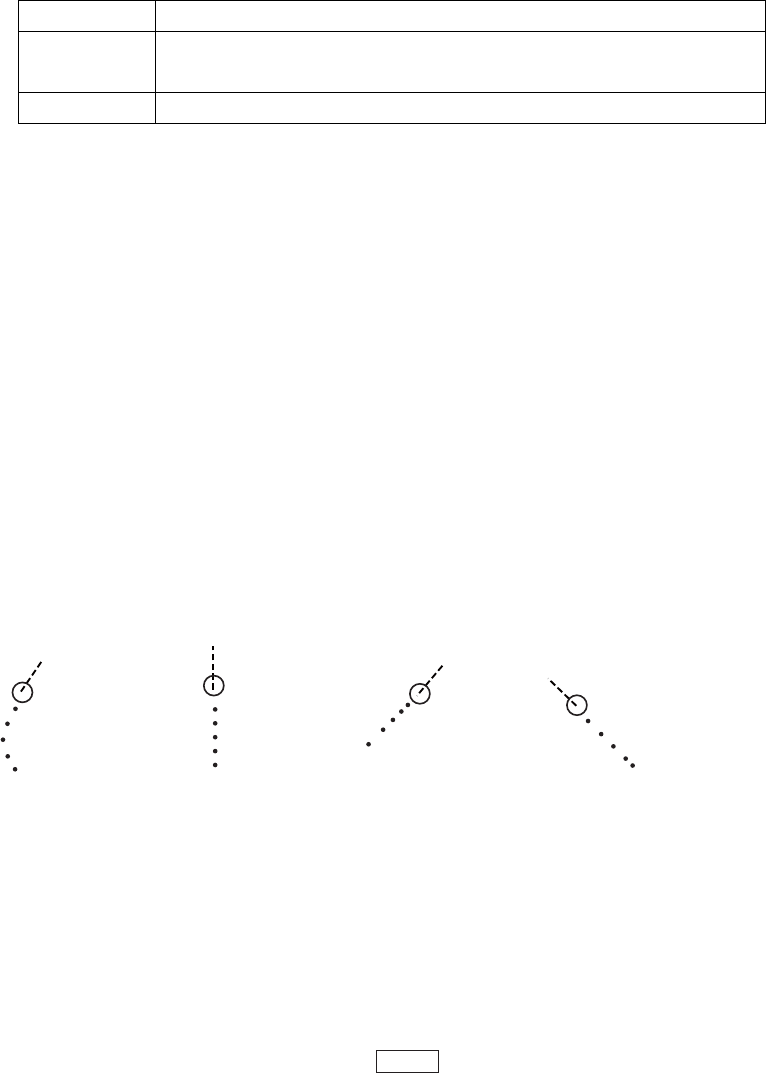
3. TARGET TRACKING (TT)
3-18
2. Push the left button to display VECTOR TRUE-S(or -G) or VECTOR REL as
appropriate. (Note that this also selects the vector mode for the past position
display.)
3. Do one of the following to select a vector time.
Control Available setting
Left button 30 sec, 1-15 min (1 min interval), 20 min, 30 min, 40 min,
50 min, 60 min
Scrollwheel 30 sec, 1-60 min (1 min interval)
The vector tip shows an estimated position of the target after the selected vector
time elapses. It can be valuable to extend the vector length to evaluate the risk
of collision with any target.
3.11 Past Position Display
The past position display shows equally time-spaced dots marking the past
positions of any targets being tracked.
A new dot is added every minute (or at other preset time intervals) until the
preset number is reached. If a target changes its speed, the spacing will be
uneven. If it changes the course, its plotted course will not be a straight line.
Past position orientation, true or relative, is controlled with TRAIL MODE on the
TRAIL menu. See section 1.30.1 for the procedure.
(a) Ship turning (b) Ship running
straight
(c) Ship reduced
speed
(d) Ship increased
speed
Past position display
3.11.1 Displaying and erasing past position points, choosing past
position plot interval
1. Use the trackball to select the PAST POSN box.
PAST POSN REL 2MIN
PAST POSN box
2. Push the left button or scrollwheel to select plot interval desired: OFF, 30
seconds, 1, 2, 3 or 6 minutes. Select OFF to erase all past position points
and deactivate the past position display.

3. TARGET TRACKING (TT)
3-19
[TT•AIS]
1 BACK
2 AZ ZONE STAB
STAB HDG/STAB NORTH
3 AZ POLYGON
OFF/STAB GND/
STAB HDG/STAB NORTH
4 [TRIAL MANEUVER]
5 [TT•AIS SYMBOL]
6 [CPA AUTO ACTIVATE]
7 [AIS DISP FILTER]
8 [AIS LOST FILTER
9 [TT LOST FILTER]
0 [ASSOCIATION]
[TT•AIS SYMBOL]
1 BACK
2 TT•AIS SYMBOL COLOR
RED*/GRN/BLU/YEL*/
CYA/MAG/WHT
3 AIS ROT TAG LIMIT
0.000°/MIN
4 TT PAST POSN POINTS
5/10
5 AIS PAST POSN POINTS
5/10
6 AIS SCALED SYMBOL
OFF/ON
3.11.2 Past position display attributes
You may select the number of past points to display per plotting interval as
follows.
1. Left-click the MENU box to open the menu.
2. Select 4 [TT•AIS].
3. Select 5 [TT•AIS SYMBOL].
* Not available on
IMO radar
TT•AIS SYMBOL menu
4. Select 4 TT PAST POSN POINTS.
5. Select 5 or 10 as appropriate.
6. Push the right button three times to close the menu.
3.11.3 Past position display mode
The display mode for the past position display is the same as that set for the TT
vector. In the true motion mode, the true vector is displayed.

3. TARGET TRACKING (TT)
3-20
[SPEED MENU]
1 SHIP SPEED
LOG(BT)/LOG(WT)/
GPS/MANUAL/REF
2 MANUAL SPEED
0.0kn
3 SET DRIFT
OFF/ON
3.11.4 Stabilization in true mode
The true mode past position display may be ground stabilized or sea stabilized.
The PAST POSN box shows current stabilization as TRUE-G or TRUE-S. To
change stabilization mode, open the SPEED menu and set SHIP SPEED to BT
(ground stabilization) or WT (sea stabilization).
3.12 Set and Drift
Set, the direction in which a water current flows, can be manually entered in
0.1-degree steps. Drift, in another word Rate, the speed of tide, can also be
entered manually in 0.1 knot steps.
When course through water and speed through water are available, activate set
and drift to get course over ground and speed over ground.
Set and drift corrections are beneficial for increasing the accuracy of vectors and
target data. Refer to the tide table on board the ship for setting information.
These values are applied to all targets. If stationary targets have vectors, set and
drift values should be adjusted until they lose vectors.
To enter set and drift do the following:
1. Right-click the SPD box to show the SPEED
menu.
2. Select 3 SET DRIFT.
3. Select ON.
4. Push the right button to close the menu. Then,
the SET and DRIFT boxes appear at the top
of the display.
5. Select the SET box.
6. Use the scrollwheel to set value, rolling it to select
numeral and pushing it to set. (Setting range: 000.0 –
359.9 (°T))
7. Select the DRIFT box.
8. Use the scrollwheel to set value, rolling it to select
numeral and pushing it to set. (Setting range: 00.0 –
19.9(kn))
Note 1: Set and drift are available when using manually input speed, speed
through the water. The speed source is shown as "WTC" (Water
Tracking Count).
Note 2: Set and drift should be checked periodically for correctness.
Note 3: Set and drift can also be adjusted with the EBL and VRM. Put the cursor
in either the SET or DRIFT box and operate the EBL for set and VRM
for drift.
SET 66.8°T
SET box
DRIFT 7.2kn
DRIFT box
3. TARGET TRACKING (TT)
3-21
3.13 TT Collision Alarm (CPA, TCPA)
The TT continuously monitors the predicted
range at the Closest Point of Approach
(CPA) and predicted time to CPA (TCPA) of
each TT. When the predicted CPA of any
TT becomes smaller than a preset CPA
range and its predicted TCPA less than a
preset TCPA limit, the audio alarm sounds
and TT COLLISION appears (in red) in the
Alert Box. In addition, the symbol of the
offending TT is red and flashes together with its vector.
This feature, when used correctly, helps prevent the risk of collision by alerting
you to threatening targets. It is important that GAIN, A/C SEA, A/C RAIN and
other radar controls are properly adjusted.
CPA and TCPA ranges must be set up properly taking into consideration the size,
tonnage, speed, turning performance and other characteristics of own ship.
The reference point for CPA and TCPA calculation may be selected from
antenna position or conning position. For further details, see section 1.50.
3.13.1 Setting the CPA and TCPA ranges
To set the CPA and TCPA ranges, do the following:
1. Left-click CPA LIMIT box to show the CPA and TCPA boxes.
CPA LIMIT 0.5NM 10MIN TCPA Box
CPA LIMIT Box CPA Box
CPA LIMIT, CPA and TCPA boxes
2. Select the CPA Box.
3. Push the left button or scrollwheel to select CPA value.
Left button 0.5, 1, 1.5, 2, 3, 4, 5, 6(nm)
Scrollwheel 0.1-20(nm), 0-10 nm in 0.1 nm increments, 10 nm
increments thereafter
4. Select the TCPA box.
5. Push the left button or scrollwheel to select TCPA value.
Left button 1, 2, 3, 4, 5, 6, 12, 15(minutes)
Scrollwheel 1-60 minutes, 1-minute increment
CAUTION
CPA/TCPA Alarm
The CPA and TCPA alarm feature should
never be relied upon as the sole means for
detecting the risk of collision.The navigator
is not relieved of the responsibility to keep
visual lookout for avoiding collisions,
whether or not the radar or other plotting
aid is in use.

3. TARGET TRACKING (TT)
3-22
3.13.2 Acknowledging the TT collision alarm
Press the [ALARM ACK] key on the keyboard, or select the ALARM ACK box
with the trackball then push the left button to acknowledge the alarm and silence
the buzzer.
The warning label TT COLLISION and the flashing of the triangle plotting symbol
and vector remain in the Alert Box until the dangerous situation is gone or you
intentionally terminate tracking of the target.
Note that when the TT COLLISION alarm is generated the AIS display is
automatically turned on.
3.14 Acquisition Zone
The acquisition zone functions both to alert you targets in a specific area and
acts as an automatic acquisition area when automatic target acquisition is active.
Any targets entering the zone will be automatically acquired.
When a target enters an acquisition zone, the buzzer sounds and the indication
TT NEW TARGET (or AIS NEW TARGET) appears (in red) in the Alert Box. The
symbol of the offending target is red and flashing. Further, the AIS display is
automatically turned on if it is off.
3.14.1 Activating an acquisition zone
One or two acquisition zones may be activated. The No. 1 acquisition zone is
available between 3 and 6 nm and the No. 2 acquisition zone can be set
anywhere when the No. 1 zone is already in use. The TT/AIS acquisition zone’s
lines are white and dashed so as to distinguish them from the radar target alarm.
The procedure below shows how to set an acquisition zone, using the example
at the bottom of the page.
1. Use the trackball to select one of the AZ (Acquisition Zone) boxes at the right
side of the screen.
AZ 1
AZ 2
Acquisition zone status
Blank: Cancel acquisition zone
SET: Set acquisition zone
WORK:
Activate acquisition zone
SLEEP: Sleep acquisition zone
AZ boxes
2. Push the left button. The AZ box now reads "AZx SET."
3. Put the cursor on point A then push the left button.
4. Put the cursor on point B then push the left button. The AZ box now reads
"AZx WORK."
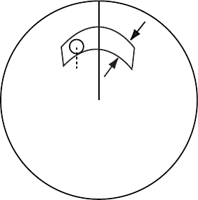
3. TARGET TRACKING (TT)
3-23
0.5-1 nm
Target in acquision zone is
red and flashing.
A
B
If you are setting a polygon acquisition zone with AZ2, set at least three points.
Push the right button to finish. Note that the status indication should be WORK
or SLEEP to set AZ2.
When a TT or AIS target enters the zone, the indication TT NEW TARGET or AIS
NEW TARGET appears (in red) in the Alert Box and the offending target flashes.
For the AIS, all sleeping targets are changed to activated targets.
Note 1: If you wish to create an acquisition zone having a 360-degree coverage
around own ship, set point B in almost the same direction (approx. ±3°)
as point A then push the left button.
Note 2: If the range scale is changed to less than half of the acquisition zone,
"Azx (x=1 or 2) OUT" is shown in light-blue in the AZ box.If the left
button is pushed in this state, the acquisition zone goes into "sleep"
state and the guidance box reads "AZ WORK L = DELETE."
Note 3: The default acquisition zone is fan shaped. It may also be a polygon
having 3-10 points. For details, see section 3.14.5.
Note 4: If both acquisition zones are displayed, maximum of four polygon points
are shown.
Note 5: TT and AIS are automatically set to TT=AUTO and AIS=DISP,
respectively, when an AZ is activated in the following conditions:
TT: TT=OFF or TT=MANUAL 100
AIS: AIS FUNC=OFF or AIS DISP=OFF
3.14.2 Sleeping, deactivating an acquisition zone
1. Select the appropriate AZ box.
2. Sleep or deactivate the alarm zone as appropriate:
Sleep alarm zone: Push the left button to remove the acquisition zone from
the screen. The indication in the AZ box changes from "AZx WORK" to "AZx
SLEEP." To reactivate and display the acquisition zone, repeat this
procedure to display "AZx WORK."
Deactivate alarm zone: Push and hold down the left button until the AZ box
goes blank.
3.14.3 Acknowledging the alarm
Press the [ALARM ACK] key, or select the ALARM ACK box then push the left
button to acknowledge the alarm and silence the buzzer.

3. TARGET TRACKING (TT)
3-24
[TT•AIS]
1 BACK
2 AZ STAB
STAB HDG/STAB NORTH
3 AZ POLYGON
OFF/STAB GND/
STAB HDG/STAB NORTH
4 [TRIAL MANEUVER]
5 [TT•AIS SYMBOL]
6 [CPA AUTO ACTIVATE]
7 [AIS DISP FILTER]
8 [AIS LOST FILTER
OFF/ON
9 [TT LOST FILTER]
0 [ASSOCIATION]
3.14.4 Acquisition zone reference
The acquisition zone may be referenced to heading or North as follows:
1. Left-click the MENU box to open the menu.
2. Select 4 [TT•AIS] to open the TT•AIS menu.
TT•AIS menu
3. Select 2 AZ STAB.
4. Select STAB HDG or STAB NORTH as appropriate.
STAB HDG: Acquisition zone keeps position relation with your ship.
STAB NORTH: Acquisition zone is fixed to North.
5. Push the right button twice to close menu.
3.14.5 Acquisition zone shape and stabilization
The shape of the No. 2 acquisition zone may be a sector or a polygon having up
to 10 points. (The shape of the No.1 acquisition zone is always a sector.)
1. Left-click the MENU box to open the menu.
2. Select 4 [TT.AIS] to open the TT.AIS menu.
3. Select 3 AZ POLYGON.
4. Select OFF, STAB GND, STAB HDG or STAB NORTH as appropriate.
OFF: Acquisition zone is a sector; number of points is limited to
four. Stabilized against land.
STAB GND: Polygon having 3-10 points. Stabilized against ground.
STAB HDG: Polygon having 3-10 points. Stabilized against heading.
STAB NORTH: Polygon having 3-10 points. Stabilized against North.
5. Push the right button twice to close menu.

3. TARGET TRACKING (TT)
3-25
3.15 TT System Messages
There are seven main situations that cause the TT to trigger audio and visual
alarms:
• Reference target alarm
• Collision alarm
• Acquisition zone alarm
• Lost target alarm
• Target full alarm for manual acquisition
• Target full alarm for automatic acquisition
• System failure
To acknowledge the audio alarm, press the [ALARM ACK] key, or select the
ALARM ACK box then push the left button.
TT system messages
Message Meaning Action
REF TARGET LOST When the system detects a loss of a
reference target, the target symbol turns
red and flashes. At the same time, an
audio alarm is produced for one second.
The reference target mark disappears from
the screen after the reference target alarm
is acknowledged.
Press the [ALARM ACK]
key or click the ALARM
ACK box to
acknowledge.
TT COLLISION A tracked target is on collision course. Take evasive action or
terminate tracking of TT.
TT NEW TARGET Tracked target has entered an acquisition
zone. The tracked target's symbol is red
and flashing.
Press the [ALARM ACK]
key or click the ALARM
ACK box to
acknowledge.
TT LOST When the system detects a loss of a
tracked target, the lost tracked target
symbol appears in red and flashes. At the
same time, an audio alarm is produced for
one second. The lost target mark
disappears from the screen after the lost
target alarm is acknowledged.
Press the [ALARM ACK]
key or click the ALARM
ACK box to
acknowledge.
TT TARGET 95%
(AUTO) or (MAN)
Appears when capacity for
automatically(manually) tracked targets is
95% full.
TT TARGET FULL
(AUTO) or (MAN)
Appears when capacity for
automatically(manually) acquired targets is
full.
TT SYSTEM ERROR When the TT malfunctions because of
hardware error, the screen shows this
indication.
Press the [ALARM ACK]
key or click the ALARM
ACK box to
acknowledge. Reset
power to restore normal
operation.
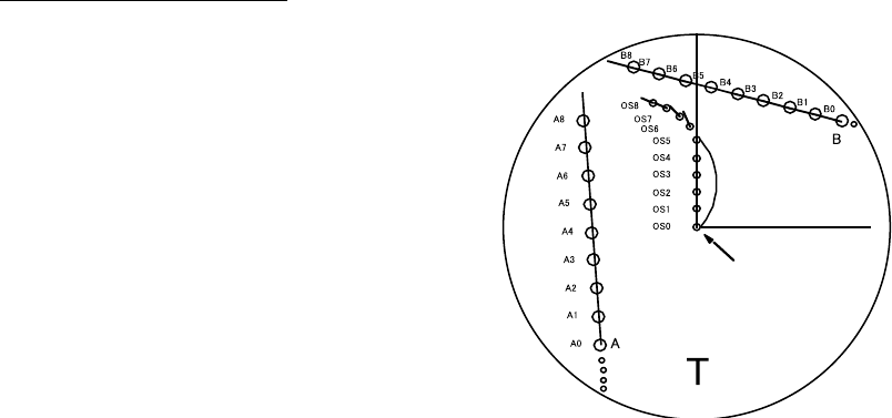
3. TARGET TRACKING (TT)
3-26
3.16 Trial Maneuver
The trial maneuver feature simulates the effect on all tracked targets against
own ship's maneuver. Enter your expected course, speed and time-to-maneuver
to find the relationship between your ship and other ships against your planned
maneuver. Further, set CPA and TCPA values to find possible collision situations.
Enter various courses and speeds until a dangerous situation is resolved. The
trial manuever feature proceeds without interrupting the updating of target
information.
For more accurate results, use relative motion and sea stabilization (ground
tracking) and be sure that own ship's characteristics such as acceleration and
turning performance have been properly set in the initial settings during the
installation. Take into consideration own ship's maneuvering characteristics such
as rudder delay, turning delay and acceleration delay. This is particularly
important on large vessels.
3.16.1 Types of trial maneuvers
There are two types of trial maneuvers: static and dynamic.
Dynamic trial maneuver
A dynamic trial maneuver displays
predicted positions of the tracked targets
and own ship. You enter own ship's
intended speed and course with a certain
"delay time." Assuming that all tracked
targets maintain their present speeds
and courses, the targets' and own ship's
future movements are simulated in
one-second increments indicating their
predicted positions in 30-second
intervals as illustrated below.
The delay time represents the time lag
from the present time to the time when own ship will actually start to change her
speed and/or course. How much the delay is set the situation starts immediately
and is updated every 0.5 seconds.
In the example shown below, own ship will advance straight ahead (even after a
maneuver) for a delay time of 2:30 then alters speed and course until
operator-specified intended speed and course are achieved (position OS5 in this
example). OS6 and OS7 show changes in course and speed and OS8 show that
the ship has completed course and speed adjustments.
Delay time = 2 m 30 s.
Present own
ship position

3. TARGET TRACKING (TT)
3-27
[TT•AIS]
1 BACK
2 AZ STAB
STAB HDG/STAB NORTH
4 AZ POLYGON
OFF/STAB GND/
STAB HDG/STAB NORTH
4 [TRIAL MANEUVER]
5 [TT•AIS SYMBOL]
6 [CPA AUTO ACTIVATE]
7 [AIS DISP FILTER]
8 [AIS LOST FILTER
OFF/ON
9 [TT LOST FILTER]
0 [ASSOCIATION]
Static trial maneuver
The static trial maneuver shows the relationship between your ship and tracked
targets at the completetion of the trial maneuver. Enter expected course and
speed and delay time until start of a maneuver and the expected position of your
ship and tracked targets at the end of the trial maneuver are shown on the
display.
By shortening and extending the trial time you can find the safe time to make a
maneuver. Thus, the static trial maneuver will be convenient when you wish to
know the maneuver result immediately.
A
B
Current position
of your ship
Delay time
T
Course and speed changes
completed; position where
course and speed are changed
Position of target A
at end of trial
maneuver
Position of target B at end
of trial maneuver
3.16.2 Performing a trial maneuver
To perform a trial maneuver, do the following:
1. Left-click the MENU box to open the menu.
2. Select 4 [TT•AIS] to open the TT•AIS menu.
TT•AIS menu
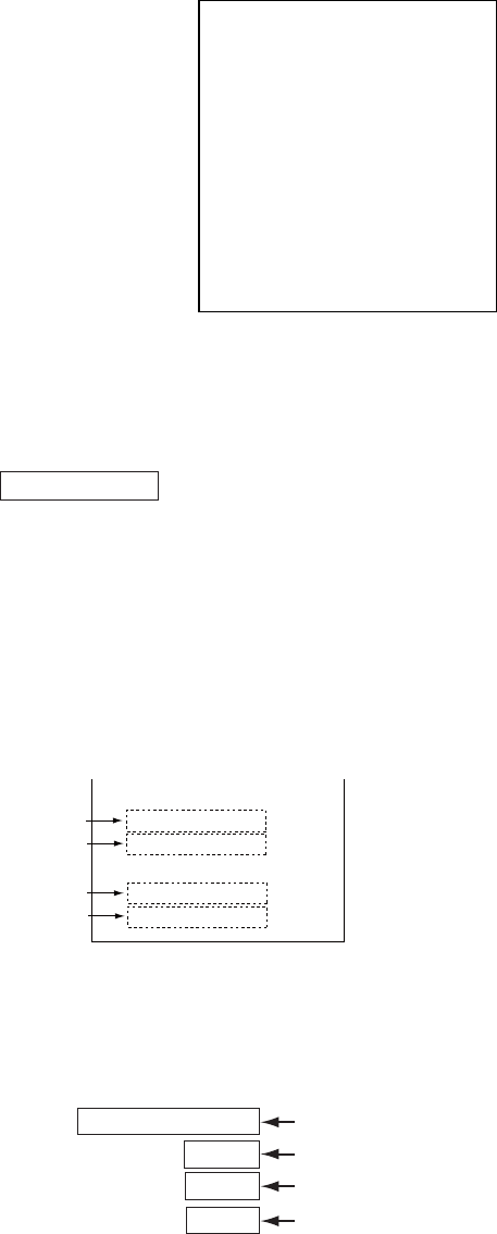
3. TARGET TRACKING (TT)
3-28
[TRIAL MANEUVER]
1 BACK
2 TRIAL
OFF/STATIC/DYNAMIC
3 TRIAL SPEED RATE
0kn 0.00kn/s
0kn 0.00kn/s
4 TRIAL TURN RATE
0kn 0.0°/s
0kn 0.0°/s
3. Select 4 [TRIAL MANEUVER].
TRIAL MANEUVER menu
4. Select 2 TRIAL.
5. Select STATIC or DYNAMIC as appropriate. The TRAIL box appears at the
upper right corner.
TRIAL OFF
6. Select 3 TRIAL SPEED RATE. Set trial speed rate with the scrollwheel, in the
upper box.
7. Select 4 TRIAL TURN RATE. Set trial turn rate with the scrollwheel, in the
upper box.
Note: Two sets of trial speed and trial turn rate combinations are provided.
Enter the data by sets as shown in the figure below. This is done to
provide accurate trial maneuver results for various ship’s speed.
3 TRIAL SPEED RATE
4
TRIAL TURN RATE
Set 1
0kt 0.00kn/s
0kt 0.00kn/s
Set 2
Set 1
0kt 0.0
°
/s
0kt 0.0
°
/s
Set 2
Set speed and turn rate to
zero (0) to simulate
course and speed changes
not affected by ship’s
inertia.
8. Push the right button three times to close the menu.
9. Use the trackball to select the TRIAL box and push the left button. Then, the
TRIAL box reads TRIAL SET and boxes appear above the TRIAL box as
below.
86.8°T
06.5kn
00:30
DELAY
TRIAL SET 00:00
Course for trial maneuver
Speed for trial maneuver
Delay time for trial maneuver
Trial time
Boxes for setting trial maneuver parameters
10. Use the scrollwheel to set delay time at DELAY. This is the time after which
own ship takes a new situation, not the time the simulation begins. Change
the delay time according to own ship loading condition, etc. Use the
scrollwheel to set the delay time.
11. Select the course setting box. Use the scrollwheel to set the course
3. TARGET TRACKING (TT)
3-29
12. Select the speed setting box. Use the scrollwheel to set the speed.
Note: Course and speed may also be set with the EBL and VRM,
respectively. Put the cursor in any one of the four trial maneuver
related boxes and operate applicable control.
13. Select TRIAL SET. Push the left button or the scrollwheel. The TRIAL box
shows "TRAIL 00:00" (00:00 is trial maneuver time).
The time indication depends on trial mode:
Dynamic mode: The position of your ship and tracked targets is updated and
displayed every 30 seconds.
Static mode: The position of your ship and tracked targets when set course and
speed are reached are displayed. The progress time until the position is reached
is indicated on the display. The trial time can be changed from the Trial Time box.
Put the cursor in the Trial Time box and roll the scrollwheel. The position of
targets at the end of selected time is shown. Increase or decrease the time to
get a safe manuever. When the cursor is removed from the box the original
positions of your ship and tracked targets are restored. If a manuever is unsafe,
change speed, course and delay until it is safe.
The trial maneuver takes place with the letter "T" displayed at the bottom of the
screen. The time appears at the top right side of the display. If any tracked target
is predicted to be on a collision course with own ship (that is, the target ship
comes within preset CPA/TCPA limits), the target plotting symbol is red. If this
happens, change own ship's trial speed, course or delay time to obtain a safe
maneuver.
3.16.3 Terminating a trial maneuver
A trial maneuver is automatically terminated at the end of the fixed time and the
normal radar display is restored. The time of termination depends on the trial
mode as follows:
Dynamic mode: The trial is terminated when 60 minutes is shown in the Trial
Time Box.
Static mode: The trial is terminated when there is no key operation within one
minute.
To terminate the trial maneuver manually, put the cursor in the Trial Time box
then push the left button to show TRAIL OFF in the box.
Note: To stop the trial maneuver, select OFF at step 5 in the procedure in
section 3.16.2.

3. TARGET TRACKING (TT)
3-30
[CUSTOMIZE•TEST]
1 BACK
2 [DATA BOX]
3 [F1]
4 [F2]
5 [F3]
6 [F4]
7 [OPERATION]
8 [TEST]
[TEST]
1 BACK
2 [SELF TEST]
3 [TT TEST]
[TT TEST]
1 BACK
2 TT TEST START
NOTE:
THE DISPLAY IS
CLEARER WHEN
RUNNING TT TEST.
RUN TT TEST?
YES: SELECT 2 START
NO: SELECT 1 BACK
3.17 TT Performance Test
A test program is provided for assessing overall performance of the TT. Normal
operation is suspended and the indication "S" appears at the bottom of the
effective display area during the test. The test may be terminated at any time.
1. Right-click the MENU box to open the menu.
2. Select 9 [CUSTOMIZE•TEST].
CUSTOMIZE•TEST menu
3. Select 8 [TEST].
TEST menu
4. Select 2 TT TEST START]
TT TEST menu
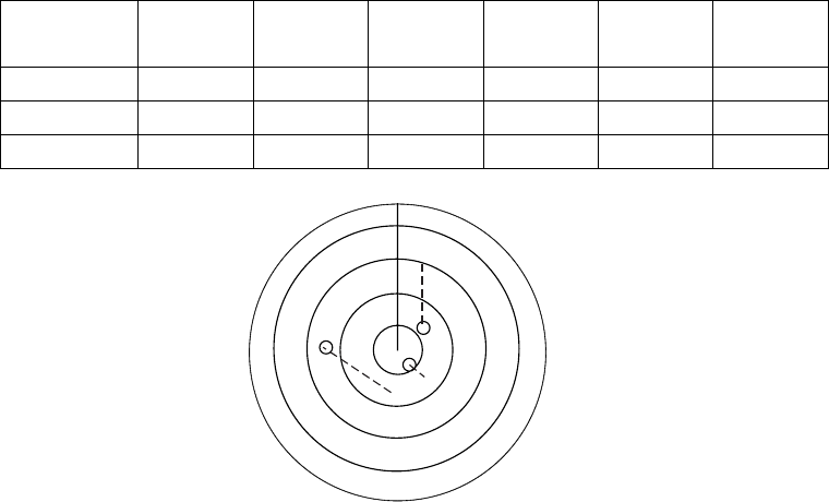
3. TARGET TRACKING (TT)
3-31
5. Select 2 TT TEST START then push the left button to start the test.
An alert "S" flickers during the test. Approx. 10 minutes to complete the test
scenario. The test does not require echo, gyro or log signals. (Gyro required
if TT W/O GYRO setting is OFF.
6. Acquire all three targets. The simulated movement of three targets
automatically runs ten minutes and repeats. The courses and speeds for the
targets are as shown in the table below.
7. Put the cursor on target A then push the [TARGET DATA] key. Target data
appears at the right side of the display.
8. Confirm that test data displayed for target A matches the data shown in the
table below. Range, bearing and TCPA change over time.
9. Confirm that data for target B and C.
10. To terminate the test, press the [STBY TX] key, or select the TX STBY box at
the bottom left corner then push the left button.
Select any target with the cursor and check that the selected target shows the
course and speed as in the table. CPA and TCPA shown in the table are with
ship’s speed of 0 kn. Range, CPA and TCPA change with time; bearing and
speed are fixed.
Range
(nm)
Bearing
(°)
Speed
(kn)
Course
(°)
CPA
(nm)
TCPA
(min)
Target A 3.0 45.0 20.0 0 2.1 -6.4
Target B 2.0 120.0 5.0 120.0 0.0 -24.0
Target C 7.0 270.0 100 120.0 3.5 3.5
A
S
C
B

3. TARGET TRACKING (TT)
3-32
3.18 Criteria for Selecting Targets for Tracking
The FURUNO TT video processor detects targets in midst of noise and
discriminates radar echoes on the basis of their size. Target whose echo
measurements are greater than those of the largest ship in range or tangential
extent are usually land and are displayed only as normal radar video. All smaller
ship-sized echoes that are less than this dimension, are further analyzed and
regarded as ships and displayed as small circles superimposed over the video
echo.
When a target is first displayed, it is shown as having zero true speed but
develops a course vector as more information is collected. In accordance with
the International Marine Organization Automatic Radar Plotting Aid (IMO TT)
requirements, an indication of the motion trend should be available within 20
scans of antenna and full vector accuracy within 60 scans. The FURUNO TTs
comply with these requirements.
Acquisition and tracking
A target which is hit by five consecutive radar pulses, is detected as a radar echo.
Manual acquisition is done by designating a detected echo with the trackball.
Automatic acquisition is done in the acquisition areas when a target is detected
5-7 times continuously depending upon the congestion. Tracking is achieved
when the target is clearly distinguishable on the display for 5 out of 10
consecutive scans, whether acquired automatically or manually. Required
tracking facilities are available within 0.1-32 nm on range scales including 3, 6,
12 nm, full plotting information is available within one scan when the range scale
has been changed.
Targets not detected in five consecutive scans become "lost targets."
Quantization
The entire picture is converted to a digital from called "Quantized Video." A
sweep range is divided into small segments and each range element is "1" if
there is radar echo return above a threshold level, or "0" if there is no return.
The digital radar signal is then analyzed by a ship-sized echo discriminator. As
the antenna scans, if there are five consecutive radar pulses with 1’s indicating
an echo presence at the exact same range, a target "start" is initiated. Since
receiver noise is random, it is not three-bang correlated, and it is filtered out and
not classified as an echo.
The same is true of radar interference. Electronic circuits track both the closet
and most distant edges of the echo. At the end of the scanning of the echo, the
discriminator indicates the measured maximum range extent and total angular
extent subtended by the echo. If the echo is larger than a ship-sized echo in
range extent and/or angular width, adjusted as a function of range, it is declared
to be a coastline and the closet edge is put into memory as a map of the area.

3. TARGET TRACKING (TT)
3-33
This land outline is used to inhibit further acquisition and tracking of ship-sized
echoes beyond the closest coast outline. Five consecutive scans of coastal
outline are retained in memory to allow for signal variation. All smaller echoes
are declared to be ship sized and the middle of the leading edge is used to
provide precise range and bearing coordinates of each echo on every scan. This
range/bearing data is matched to previous data and analyzed from scan-to-scan
for consistency. When it is determined to be as consistent as a real target,
automatic acquisition occurs and tracking is initiated. Continued tracking and
subsequent calculation develop the relative course and speed of the target.
The true course and speed of own ship are computed from own ship's gyro and
speed inputs, and the resulting course and speed of each tracked target is easily
computed by vector summing of the relative motion with own ship’s course and
speed. The resulting true or relative vector is displayed for each of the tracked
targets. This process is updated continually for each target on every scan of the
radar.
Qualitative description of tracking error
The FURUNO TT's accuracy complies with or exceed IMO standards.
Own ship maneuvers
For slow turns there is no effect. For very high turning rates (greater than
150°/minute, depending on gyro), there is some influence on all tracked targets
that lasts for a minute or two then all tracked targets revert to full accuracy.
Other ship maneuvers
Target ship courses, lag 15 to 30 seconds at high relative speed, or 3 to 6
seconds at low (near 0) relative speed. It is less accurate during a turn due to lag,
but accuracy recovers quickly.

3. TARGET TRACKING (TT)
3-34
3.19 Factors Affecting TT Functions
Sea returns
If the radar anti-clutter control is adjusted properly, there is no serious effect
because distant wave clutter, not eliminated by this control, is filtered out by
more than one bang correlation and scan-to-scan matching of data.
Rain and snow
Clutter can be acquired and tracked as targets. Adjust the A/C RAIN control. If it
is heavy rain, switch to S-band if provided, or switch on the interference rejector
on the radar. If heavy clutter still exists, switch to manual acquisition. Accuracy
can be affected.
Low clouds
Usually no affect. If necessary, adjust the A/C RAIN control.
Non-synchronous emissions
No effect.
Low gain
Insufficient or low radar receiver gain will result in some targets not being
acquired at long distance. TT display will be missing on one or more targets that
could only be visible if the radar sensitivity control (GAIN control) were
increased.
The setting of the correct radar receiver gain is not critical but the target should
be on the radar PPI and be clearly visible and well defined.
Manual acquisition is done if a target is positively displayed more than once.
Automatic acquisition is done when the target is detected 5-7 times continuously.
Tracking is achieved when the target is detected five times (not necessarily
continuously) out of 10 scans. If not detected six times out of 10 scans, the
target will become a "lost target." The TT will acquire a radar echo that is present
once in every six antenna scans and continue tracking if 1 in 10.
Second trace echoes
When the radar beam is super refracted, strong echoes may be received at such
long ranges that they appear on a different timebase sweep than the transmitted
pulse. This gives an incorrect range indication. Second and third trace echoes
can be tracked if they are consistent enough to meet acquisition and tracking
criteria but target course and speed data will be in error.

3. TARGET TRACKING (TT)
3-35
Blind and shadow sectors
Radar shadow or blind areas caused by obstructions aboard ship, for example,
funnels and masts, in the path of the radar beam can result in reduction of radar
beam intensity in that particular direction. This may eliminate the detection of
some targets. The TT system will lose track of targets shortly after they are lost
on the radar picture and if they remain in a blind zone. These targets will
however be acquired and tracked when they pass out of the blind zone and
again present normal radar echo. The angular width and bearing of any shadow
sector should be determined for their influence on the radar. In certain cases
false echoes in the shadow sector cause the TT system to acquire, track, and
vector them. Shadow sectors should be avoided.
Indirect echoes
A target at close range is usually picked up directly, but it can also be received
as reflection from a large, flat surface. This will result in the radar presenting two
or more echoes on the display, each at a different range. The TT can acquire
and track the false echo if it is detected by five consecutive scans. Reduction in
radar gain can eliminate the multiple echoing but care should be taken as range
detection also will be reduced.
Radar interference
If interference is extreme due to another radar operating at close range, spiral
"dotting" and/or false targets may appear momentarily. The interference rejector
can clear the display.
To receive radar beacon or SART signals, turn on "SART" in the ECHO menu.
3. TARGET TRACKING (TT)
3-36
This page is intentionally left blank.
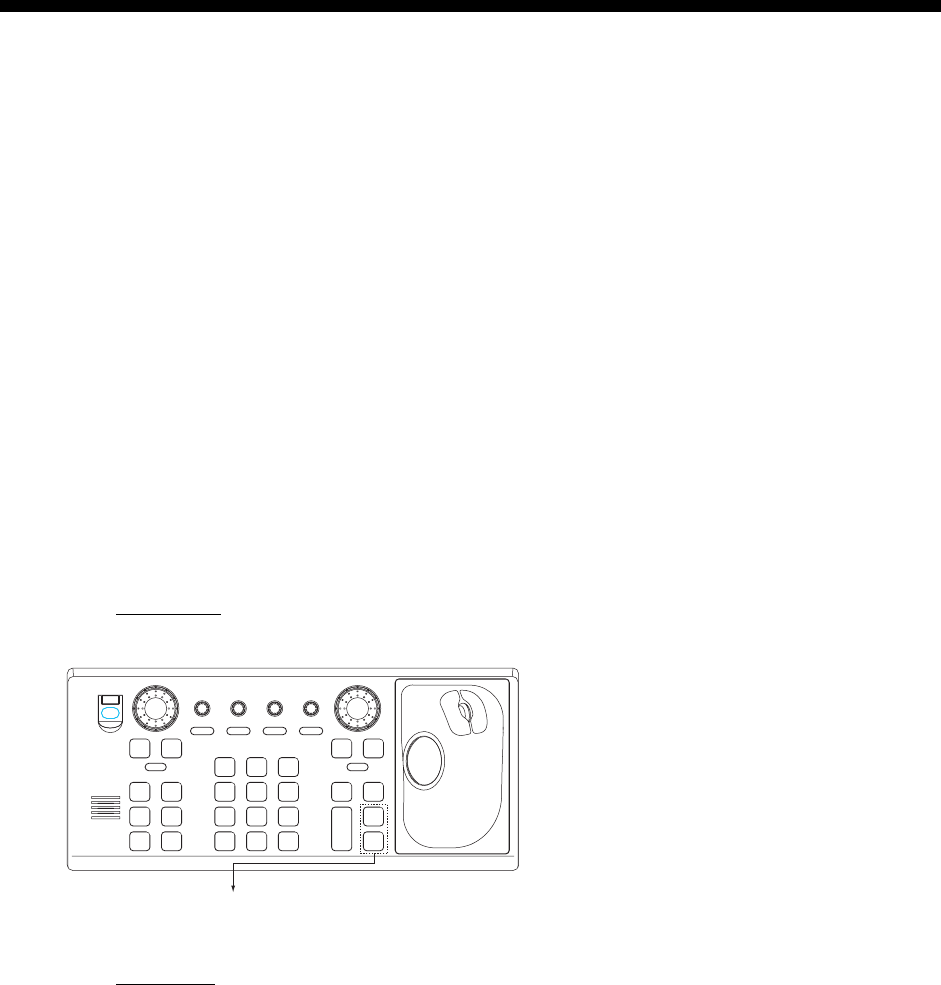
4-1
4. AIS OPERATION
The FURUNO AIS (Automatic Identification System) model FA-100 or FA-150
exchanges with other AIS-fitted ships all data and information required by the
SOLAS 1994 as amended. However, they are displayed in text form. By
interfacing the FA-100 or FA-150 with this radar, the AIS information is
graphically indicated together with the radar and TT information.
For the IMO specification, position data must be fixed by WGS-84 geodetic
datum and speed input must be ground tracking. If other type of datum is input,
the error message "DATUM" appears and the AIS feature is inoperative. This
restriction does not apply to other types.
When AIS is active, MANUAL and REF in the speed source selection window
are shown in gray to indicate they are not available for selection.
You may disable or enable the AIS display from the AIS DISP box.
4.1 Controls for AIS
Keyboard
The AIS uses the keys shown below.
ACQ
ON
MENU
OFF
VRM
A/C SEAA/C RAIN
MODE
3
LINE
INDEX
6
OFF
21
HL
CENTER
OFF
45
RESET
CU/TM
OFFSET
EBL
GAIN
TARGET
CANCEL
TARGET
DATA
RANGE
-
+
LIST
TARGET
9
MARK
ENTER
TIME
VECTOR
78
CANCEL
TRAILS
0
MODE
VECTOR
BRILL
BRILL
EBL
F1
OFF
F2
ON
POWER
ACK
ALARM
F3 F4
STBY
TX
TARGET DATA: Displays data on AIS target
selected by the trackball.
TARGET CANCEL: Sleeps chosen AIS target.
Control unit RCU-014
Trackball
With the cursor inside the effective display area, you can access AIS functions
by rolling the scrollwheel or choosing appropriate AIS function from the
CURSOR menu.
Roll the scrollwheel to show the following indications in the guidance box to
access respective AIS function:
TARGET DATA & ACQ: Displays target data for AIS target selected with the
trackball; activates chosen AIS target.
TARGET CANCEL: Sleeps selected AIS activated target.
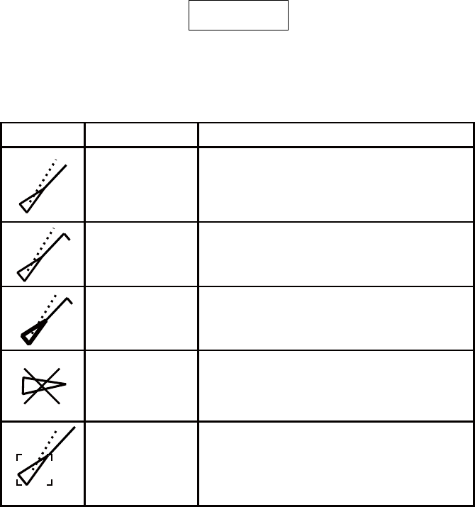
4. AIS OPERATION
4-2
4.2 Showing, Hiding the AIS Display
Left-click the AIS DISP box at the right side of the screen to show or hide the AIS
display and set display criteria.
DISP ALL: All AIS targets received from the AIS transponder are displayed with
symbols.
DISP FILT: AIS targets are displayed according to the criteria set with AIS DISP
FILTER on the AIS/TT menu. See section 4.3 for details.
DISP OFF: All AIS symbols disappear, but tracking continues internally.
AIS
OFF
DISP
AIS DISP box
When the AIS is turned on, AIS targets are marked with appropriate AIS symbol
as below.
SYMBOL STATUS REMARKS
Activated
target
ROT higher
than preset
ROT
Dangerous
target
Lost target
Target selected
for data display
All AIS symbols shown with thick line.
Color is selectable from menu.
Displayed for turning ship.
Displayed when CPA/TCPA is within
CPA/TCPA LIMIT. Red in color. Flashing
until acknowledged..
A
“X” overlaid on a lost target. Red in
color. Erased after acknowledged.
Broken square is overlaid on target
selected to display its data. A, B or C
shown to indicate data box location (at
the right side of the screen).
AIS symbols
Note 1: The equipment continues to process AIS targets when the AIS feature is
switched off. When the AIS is again turned on, symbols are immediately
displayed.
Note 2: You can turn the AIS display off by putting the cursor in the AIS box and
long-pushing the left button to show FUNC OFF. Data processing is
terminated.
Note 3: AIS symbols are momentarily erased and the screen is redrawn after the
heading is changed in the head-up mode.
Note 4: When no AIS data is received, the message "RECEIVE" appears in the
Alert Box. Check the AIS transponder.

4. AIS OPERATION
4-3
Note 5: AIS symbols are shown in dotted lines in the following cases:
- No water or ground tracking speed of your ship, or there is no speed
data. All AIS symbols are shown in dotted lines and the message "NO
CPA/TCPA for AIS" appears (in red) in the Alert Box.
- No water or ground tracking speed received from AIS target, or no
speed data from AIS target. The symbol of the corresponding AIS
target is shown in dotted lines.
Note 6: Other AIS symbols that may appear are shown in the table below.
Symbol Meaning
Real AIS AtoN
Virtual AIS AtoN
Base Station
Airborne SAR aircraft
+
+
AIS SART
Note 7: The CPA and TCPA of SAR aircraft data are not available, and are
shown as ***.

4. AIS OPERATION
4-4
[TT•AIS MENU]
1 BACK
2 AZ STAB
STAB HDG/STAB NORTH
3 AZ POLYGON
OFF/STAB GND/
STAB HDG/STAB NORTH
4 [TRIAL MANEUVER]
5 [TT.AIS SYMBOL]
6 [CPA AUTO ACTIVATE]
7 [AIS DISP FILTER]
8 [AIS LOST FILTER]
9 [TT LOST FILTER]
0 [ASSOCIATION]
[AIS DISP FILTER]
1 BACK
2 MAX RANGE
OFF/ON
0NM
3 MIN SHIP SPEED
OFF/ON
0.0kn
4 EXCEPT CLASS B
OFF/ON
5 MIN SHIP LENGTH
OFF/ON
0M
4.3 AIS Display Filter
If there are too many AIS targets on the screen you may wish to remove
unnecessary ones. You may remove targets by distance from own ship, speed,
class and length. For example, you might want to remove slow moving targets,
as they normally do not require close monitoring.
1. Left-click the MENU box to open the menu.
2. Select 4 [TT●AIS] to open the TT●AIS menu.
TT/AIS menu
3. Select 7 [AIS DISP FILTER].
AIS DISP FILTER menu
4. Set items 2-5 referring to the description below.
MAX RANGE: Any AIS target beyond the range set here will not be shown.
MIN SHIP SPEED: Any AIS target slower than this setting will not be shown.
EXCEPT CLASS B: Select ON to remove Class B AIS targets.
MIN SHIP LENGTH: Any AIS target whose length is shorter than this setting
will not be shown.
5. Push the right button twice to close the menu.
6. Select "DISP FILT" from the AIS DISP box.
Note: An AIS target whose data is currently displayed is not affected by the
filter setting.
If the AIS DISP box is operated
when all settings on this menu are
set for OFF, the setting of the AIS
DISP box becomes DISP ALL.
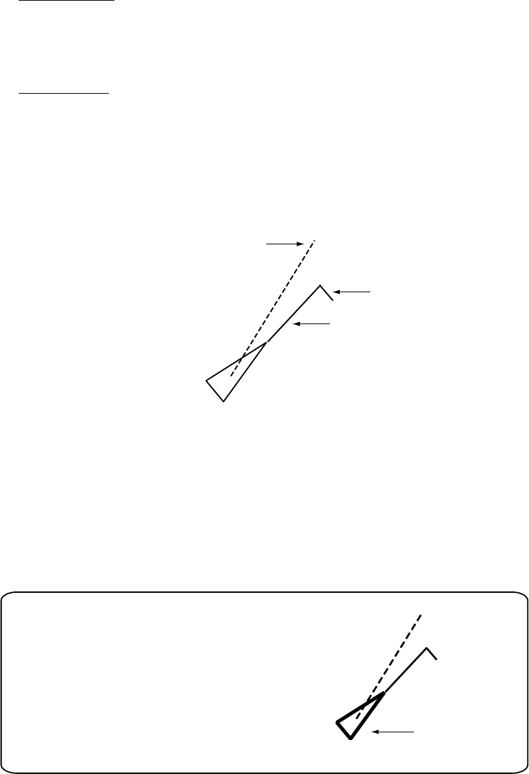
4. AIS OPERATION
4-5
4.4 Activating Targets
When you convert a sleeping target to an activated target, that target’s course
and speed are shown with a vector. You can easily judge target movement by
monitoring the vector.
Sleeping targets within an acquisition zone are automatically changed to
activated targets and are colored red. See section 3.14 for details.
4.4.1 Activating specific targets manually
By keyboard
1. Use the trackball to put the cursor on the AIS target you wish activate.
2. Press the [TARGET DATA] key to activate the target.
By trackball
1. With the cursor inside the effective display area, roll the scrollwheel to
display "TARGET DATA & ACQ / CURSOR MENU" in the guidance box.
2. Use the trackball to put the cursor on the sleeping AIS target you wish to
activate; that is, know more about a vessel’s motion.
3. Push the left button to activate the target.
Heading line *
2
SOG (Speed over Ground)
and COG (Course over Ground) vector
*
1
Turning direction
(ROT)
*
1
Vector shows STW (speed
thru water) and CSE
(course) when water
tracking mode is
selected at the radar.
*
2
If there is no heading data,
the line points in direction of COG.
Activated target
4.4.2 Activating all targets
1. Right-click the AIS DISP box to open the AIS TARGET menu.
2. Select 2 ACTIVATE ALL TRGTS.
3. Push the right button to close the menu.
Thicker than
activated target
Dangerous target
When an activated target violates the CPA/TCPA
alarm setting its symbol changes to the dangerous
target symbol (red and flashing) and the indication
AIS COLLISON appears. Press the [ALARM ACK] key
(or click the ALARM ACK box with the left button)
to acknowledge the CPA/TCPA alarm. The audible
alarm is silenced and the symbol stops flashing.
Take appropriate action to avoid collision.

4. AIS OPERATION
4-6
4.5 How to Sleep Targets
4.5.1 Sleeping an individual target
You may "sleep" an AIS target as below when the screen becomes filled with
targets, which might prevent important radar and AIS displays from being
identified. Note that targets that have been activated automatically cannot be
"slept."
1. With the cursor inside the effective display area, roll the scrollwheel to
display "TARGET CANCEL / EXIT" in the guidance box.
2. Use the trackball to put the cursor on an activated AIS target symbol.
3. Push the left button. The activated target symbol is replaced with the
sleeping target symbol.
Sleeping target
4.5.2 Sleeping all targets
1. Right-click the AIS DISP box to open the AIS TARGET menu.
[AIS TARGET MENU]
1 SLEEP ALL TRGTS
NO/YES
2 ACTIVATE ALL TRGTS
NO/YES
3 AUTO DISP MESSAGES
OFF/ON
4 [RECEIVED MESSAGES]
5 [TRANSMIT MESSAGE]
6 [VOYAGE DATA]
7 [STATIC DATA]
8 [AIS ALM MESSAGES]
AIS TARGET menu
2. Select 1 SLEEP ALL TRGTS.
3. Select YES to sleep all AIS targets.
4. Push the right button to close the menu.

4. AIS OPERATION
4-7
[VOYAGE DATA]
1 BACK
2 NAVIGATION STATUS
03
RESTRICTED
MANOEVRABILITY
3 ETA
00/000/0000 00:00
4 DESTINATION
12
5 DRAUGHT
00.0m
6 CREW
0002
4.6 Setting Up for a Voyage
There are five items on the VOYAGE DATA menu you will need to enter at the
start of a voyage: navigational status, ETA, destination, draught and crew.
1. Right-click the AIS DISP box at the right side of the screen to open the AIS
TARGET menu.
[AIS TARGET MENU]
1 SLEEP ALL TRGTS
NO/YES
2 ACTIVATE ALL TRGTS
NO/YES
3 AUTO DISP MESSAGES
OFF/ON
4 [RECEIVED MESSAGES]
5 [TRANSMIT MESSAGE]
6 [VOYAGE DATA]
7 [STATIC DATA]
8 [AIS ALM MESSAGES]
AIS TARGET menu
2. Select 6 VOYAGE DATA.
VOYAGE DATA menu
3. Select 2 NAVIGATION STATUS.
4. AIS OPERATION
4-8
4. Select appropriate navigation status number referring to the information
below then push left button.
00: Underway using engine (default)
01: At anchor
02: Not under command
03: Restricted manoeuverability
04: Constrained by her draft
05: Moored
06: Aground
07: Engaged in fishing
08: Under way sailing
09: Reserved for high speed craft (HSC)
10: Reserved for wing in ground (WIG, for example, hydrofoil)
11-13: Reserved for future use
14: AIS SART (No use)
15: Not defined
5. Select 3 ETA then push the left button.
6. Use the scrollwheel to enter estimated date and time of arrival, in order of
day (two digits), month, year (four digits) and time. Push the scrollwheel after
entering the data.
7. Select 4 DESTINATION.
8. Enter destination: Select alphanumeric character, push the scrollwheel to
enter.
9. Select 5 DRAUGHT.
10. Roll the scrollwheel to set ship’s draught (setting range: 0-25.5 m) then push
the scrollwheel.
11. Select 6 CREW.
12. Roll the scrollwheel to set number of crew (0–8191) then push the
scrollwheel.
13. Push the right button to close the menu.
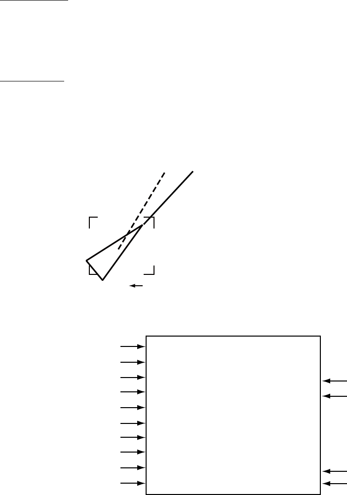
4. AIS OPERATION
4-9
4.7 Target Data
You may display an AIS target’s data by selecting it on the display, when the AIS
function is set for "AIS DISP FILT".
4.7.1 Basic target data
By keyboard
1. Use the trackball to put the cursor on the AIS target symbol you want to know
its data.
2. Press the [TARGET DATA] key.
By trackball
1. With the cursor inside the effective display area, roll the scrollwheel to
display "TARGET DATA & ACQ / CURSOR MENU".
2. Use the trackball to put the cursor on an AIS target symbol. The selected
target is marked with a broken square and AIS data is shown in the AIS data
box when the target is correctly selected.
A
Location of target’s data box.
Not shown on W-type radar.
Activated target selected for data display
AIS B MMSI 665498114
VOYAGER
BRG 208.6
°
T
RNG 12.3NM
TCOG 9.0
°
T*
TSOG 8.2kn#
CPA 5.32NM
TCPA 33:31
BCR 5.65NM
BCT 25:30
* = CSE (course) when water tracking mode is selected at radar.
# = STW (speed thru water) when water tracking mode is selected at radar.
Position
Location of target data, MMSI No.
Rate of turn
Heading
Bearing to target
Range to target
Target's course
Target's speed
Target's CPA
Target's TCPA
Target's bow cross range
Target's bow cross time
34
°
37.912 N
135
°
21.569 E
NAV-STATUS
UNDER WAY
USING ENGINE
HDG 048.0
°
T
0.0
°
/min
Name of ship
Nav status
AIS data display
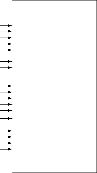
4. AIS OPERATION
4-10
4.7.2 Detailed target data
1. Use the trackball to put the cursor on the desired AIS target in the data box at
the right side of the screen.
2. Push the left button to show detailed data.
[EXPANDED DATA]
NAME:
VOYAGER
CALL: WRE45T
LAT: 34
°
44.2345'N
LON: 135
°
32.1890'E
POS. SENSOR
GPS
POS. ACC.: HIGH
NAV. STATUS
UNDERWAY
USING ENGINE
MMSI No.: 107374182
IMO No.: 123544876
SHIP LENGTH: 55m
SHIP WIDTH: 15m
SHIP DRAFT: 2.8m
DESTINATION
KOBE
ETA: 01/FEB 12:59
AIS VERSION: 0
ASSOCIATION: OFF
SHIP & CARGO TYPE:
CARGO SHIPS
ALL SHIPS OF
THIS TYPE
Ship's name
Call sign
Latitude
Longitude
Position fixing device
Position accuracy (HIGH, LOW)
Navigation status
MMSI No.
IMO No.
Length
Width
Draft
Destination
Estimated Time of Arrival
AIS program no.
Assocation ON/OFF
Type of ship and cargo
Expanded data
4.7.3 Removing a target data display
Put the cursor on the data you want to remove and hit the [TARGET DATA] key.
4.7.4 Canceling tracking on a target from target data display
Put the cursor on the target you want to stop tracking and hit the [TARGET
CANCEL] key.

4. AIS OPERATION
4
-
11
4.8 AIS Symbol Attributes
You may adjust the brilliance and select the size and color of the AIS symbol.
4.8.1 AIS symbol brilliance
1. Right-click the BRILL box at the left side of the screen.
2. Select 0 NEXT.
[BRILL1 MENU (2/2)]
1 BACK
2 BRG CURSOR
3 EBL
4 VRM
5 PI LINE
6 TT SYMBOL
7 AIS SYMBOL
8 L/L GRID
9 MARK
0 CHART* * Not available on IMO type
BRILL menu, page 2
3. Select 7 AIS SYMBOL.
4. Roll the scrollwheel to adjust brilliance.
5. Push the right button twice to close the menu.
4.8.2 AIS symbol size and color
You may select the size and color of the AIS symbol as follows:
1. Left-click the MENU box to open the menu.
2. Select 4 [TT/AIS].
3. Select 5 [TT/AIS SYMBOL].
[TT
.
AIS SYMBOL]
1BACK
2TT
.
AIS SYMBOL COLOR
RED*/GRN/BLU/YEL*/
CYA/MAG/WHT
3 AIS ROT TAG LIMIT
000.0˚/min
4 TT PAST POSN POINTS
5/10
5 AIS PAST POSN POINTS
5/10
6 AIS SCALED SYMBOL
OFF/ON * Not available on IMO type
AIS SYMBOL menu
4. Select 2 TT•AIS SYMBOL COLOR.
5. Select color desired.
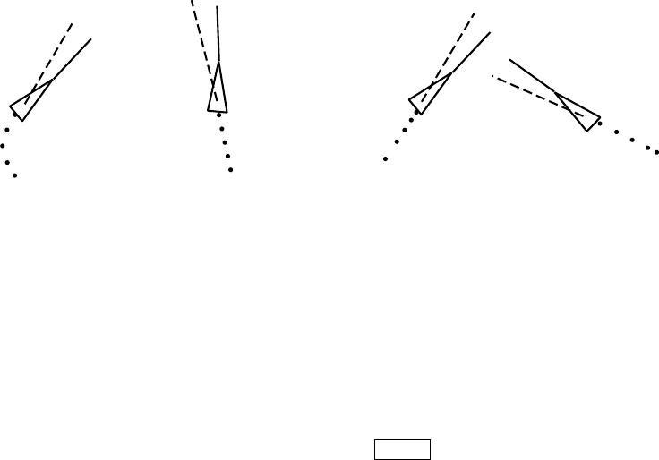
4. AIS OPERATION
4-12
6. Select 6 AIS SCALED SYMBOL.
7. Select OFF or ON as applicable.
OFF: All AIS symbols shown in same size.
ON: All AIS symbols are scaled according to ships' lengths.
8. Push the right button three times to close the menu.
4.9 Past Position Display
The past position display shows equally time-spaced dots marking past positions
of activated AIS targets. A new dot is added at preset time intervals until the
preset number is reached. If a target changes its speed, the spacing will be
uneven. If it changes course, its plotted course will not be a straight line.
Note that AIS past positions will be shown if TARGET TRACK on the DISPLAY
sub menu of the PLOTTER menu is ON, regardless of whether AUTO TARGET
TRACK on the PLOTTER menu is turned ON or OFF.
Below are sample past position displays.
(a) Ship turning (b) Ship running
straight
(c) Ship reduced
speed
(d) Ship increased
speed
Sample past position displays
4.9.1 Past position plot interval
Left-click the PAST POSN box at the right side of the screen to select plot
interval desired: OFF, 30 s, 1, 2, 3 or 6 min. Select OFF to erase all past position
points and turn off the past position display.
PAST POSN REL 2MIN
PAST POSN box

4. AIS OPERATION
4-13
4.9.2 Past position points
You may select the number of past position points to show per plot interval as
follows:
1. Left-click the MENU box to open the menu.
2. Select 4 [TT/AIS] to open the TT.AIS menu.
3. Select 5 [TT/AIS SYMBOL].
[TT
.
AIS SYMBOL]
1BACK
2TT
.
AIS SYMBOL COLOR
RED*/GRN/BLU/YEL*/
CYA/MAG/WHT
3 AIS ROT TAG LIMIT
000.0˚/min
4 TT PAST POSN POINTS
5/10
5 AIS PAST POSN POINTS
5/10
6 AIS SCALED SYMBOL
OFF/ON * Not available on IMO type
AIS SYMBOL menu
4. Select 5 AIS PAST POSN POINTS.
5. Select 5 or 10 as appropriate.
6. Push the right button three times to close the menu.
4.9.3 Past position display motion
The past position display may be shown in true or relative motion. Open the
TRAIL menu and set TRAIL MODE to TRUE or RELATIVE as appropriate.
4.9.4 Stabilization in true motion
The true motion past position display may be ground stabilized or sea stabilized.
The PAST POSN box shows current stabilization as TRUE-G or TRUE-S. To
change the stabilization mode, open the SPEED menu and set SHIP SPEED to
BT (ground stabilization) or WT (sea stabilization).

4. AIS OPERATION
4-14
[AIS LOST FILTER]
1 BACK
2 MAX RANGE
OFF/ON
0NM
4 MIN SHIP SPEED
OFF/ON
0.1kn
5 EXCEPT CLASS B
OFF/ON
5 MIN SHIP LENGTH
OFF/ON
0M
4.10 Lost Target
A target is declared a lost target when it fails to produce data for six minutes or
five reporting intervals, whichever is the shorter. When this occurs, the target is
marked with the (flashing) lost target symbol and the indication "LOST" appears
in the Alert Box. To acknowledge a lost target, press the [ALARM ACK] key, or
use the trackball to select the ALARM ACK box then push the left button.
Lost target
Note 1: If a TT lost target mark is displayed when the [ALARM ACK] key is
pressed (or the ALARM ACK box is clicked) to acknowledge an AIS lost
target, the TT lost target also is erased.
Note 2: The AIS data transmission interval depends on target’s speed. For
example, the data is transmitted every 10 seconds on ship speed of 0 to
14 knots and every two seconds on the ship speed of more than 23
knots. For details see the owner’s manual of the AIS.
4.10.1 Lost target filter
If there are a lot of AIS targets in your area, the lost target alarm may sound
frequently. In this case you may wish to have the alarm ignore lost targets whose
range, speed, class or length are below the threshold value you specify.
1. Left-click the MENU box to open the menu.
2. Select 4 [TT●AIS] to open the TT.AIS menu.
3. Select 8 [AIS LOST FILTER].
AIS LOST FILTER menu

4. AIS OPERATION
4-15
4. Set items 2-5 as appropriate, referring the description below.
MAX RANGE: Any AIS lost targets beyond this range will not trigger
the lost target alarm.
MIN SHIP SPEED: Any AIS lost targets slower than this setting will not
trigger the lost target alarm.
EXCEPT CLASS B: Select ON to prevent trigger lost B class AIS lost
target.
MIN SHIP LENGTH: Any AIS lost targets whose length is shorter than this
setting will not trigger the lost target alarm.
5. Push the right button several times to close the menu.
4.10.2 Enabling, disabling the lost target alarm
The LOST TARGET ALARM box at the bottom right corner enables and disables
the lost target alarm. Select OFF, ALL or FILT as appropriate.
OFF: Disable the alarm.
ALL: Get the alarm against all lost targets.
FILT: Get the alarm against the AIS targets whose criteria meet
the settings on the AIS LOST FILTER menu.
CPA AUTO ACTIVATE OFF
CPA AUTO ACTIVATE box

4. AIS OPERATION
4-16
4.11 ROT Setting
You may set the lower limit of the ROT (Rate Of Turn) at which the heading line
on target symbols will point in direction of turning of the vessel.
1. Left-click the MENU box to open the menu.
2. Select 4 [TT/AIS] to open the TT/AIS menu.
[TT
.
AIS SYMBOL]
1BACK
2TT
.
AIS SYMBOL COLOR
RED/GRN/BLU/YEL/
CYA/MAG/WHT
3 AIS ROT TAG LIMIT
000.1˚/min
4 TT PAST POSN POINTS
5/10
5 AIS PAST POSN POINTS
5/10
6 AIS SCALED SYMBOL
OFF/ON
AIS SYMBOL menu
3. Select 3 AIS ROT TAG LIMIT.
4. Use the numeral keys or the scrollwheel to enter ROT (setting range: 0.1 to
720.0 (°/min)).
5. Push the right button three times to close the menu.
Ship turning
to starboard
ROT display
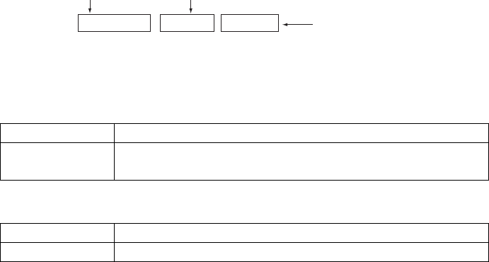
4. AIS OPERATION
4-17
4.12 AIS Collision Alarm (CPA, TCPA)
The AIS continuously monitors the predicted range at the Closest Point of
Approach (CPA) and predicted time to CPA (TCPA) of each AIS target. When the
predicted CPA of an AIS target becomes smaller than a preset CPA range and its
predicted TCPA less than a preset TCPA limit, the audio alarm sounds and AIS
COLLISION appears (in red) in the Alert Box. In addition, the symbol of the
offending AIS target is red and flashes together with its vector.
CPA/TCPA alarm ranges must be set up properly taking into consideration the
size, tonnage, speed, turning performance and other characteristics of own ship.
The reference point for CPA, TCPA calculation may be selected from antenna
position or conning position. For further details, see section 1.50.
4.12.1 Setting the CPA and TCPA ranges
To set the CPA and TCPA ranges, do the following:
1. Left-click CPA LIMIT box to show the CPA and TCPA boxes. (Not necessary if
the CPA and TCPA boxes are already shown.)
CPA LIMIT 0.5NM 10MIN TCPA Box
CPA LIMIT Box CPA Box
CPA LIMIT, CPA and TCPA boxes
2. Select the CPA Box.
3. Push the left button or scrollwheel to select CPA value.
Left button 0.5, 1, 1.5, 2, 3, 4, 5, 6(nm)
Scrollwheel 0.1-20(nm), 0-10 nm in 0.1 nm increments, 10 nm
increments thereafter
4. Select the TCPA box.
5. Push the left button or scrollwheel to select TCPA value.
Left button 1, 2, 3, 4, 5, 6, 12, 15(minutes)
Scrollwheel 1-60 minutes, 1-minute increment
4.12.2 Enabling, disabling the AIS collision alarm
Use the CPA AUTO ACTIVATE box at the bottom right corner to enable or
disable the AIS collision alarm.
OFF: Disable automatic activation.
ALL: Activation against AIS targets whose CPA or TCPA is less than set in
section 4.12.1.
FILT: Alarm is given against AIS targets which meet the following criteria:
- AIS target that meets the criteria set with 6 CPA AUTO ACTIVATE on the
TT●AIS menu.
- CPA or TCPA of an AIS target is smaller than that set in section 4.12.1

4. AIS OPERATION
4-18
[CPA AUTO ACTIVATE]
1 BACK
2 MAX RANGE
OFF/ON
0NM
3 MIN SHIP SPEED
OFF/ON
0.0KN
4 EXCEPT CLASS B
OFF/ON
5 MIN SHIP LENGTH
OFF/ON
0M
CPA AUTO ACTIVATE OFF
CPA AUTO ACTIVATE box
4.12.3 Limiting the function of the collision alarm
You can limit the function of the collision alarm by distance from own ship, ship's
speed, ship class, and ship's length.
1. Left-click the MENU box to open the menu.
2. Choose 4 TT●AIS.
3. Choose 6 [CPA AUTO ACTIVATE].
CPA AUTO ACTIVATE menu
4. Set items 2-5 as appropriate.
MAX RANGE: Any AIS target beyond this range will not be
automatically activated.
MIN SHIP SPEED: Any AIS targets slower than this setting will not be
automatically activated.
EXCEPT CLASS B: Select ON to prevent automatic activation of class B
AIS targets.
MIN SHIP LENGTH: Any AIS targets whose length is shorter than this setting
will not be automatically activated.
5. Push the right button several times to close the menu.

4. AIS OPERATION
4-19
[ASSOCIATION]
1 BACK
2 ASSOCIATION TARGET
OFF/AIS/TT
3 GAP
0.050NM
4 RANGE
0.100NM
5 BEARING
9.9°
6 SPEED
6.0kn
7 COURSE
25.0°
4.13 Association of TT and AIS Targets
If the target data from AIS and TT are both available, and if the association
criteria (for example position, motion) are fulfilled such that the AIS and TT are
considered as one physical target, the activated AIS (or TT) target symbol and
the alphanumeric AIS (or TT) target data is automatically selected and
displayed.
If the AIS and radar information become sufficiently different, the AIS and radar
information shall be considered as two distinct targets. One activated AIS target
and one tracked radar target shall be displayed.
1. Confirm that the TT ACQ MODE box shows AUTO, AUTO MAN or MAN.
2. Left-click the MENU box to open the menu.
3. Select 4 [TT●AIS] to open the TT/AIS menu.
4. Select 0 [ASSOCIATION] to show the ASSOCATION menu, shown right.
5. Select ASSOCIATION TARGET.
6. Select OFF, AIS or TT as applicable to select which symbols and data to
show when association criteria is met.
OFF: Turn off association.
AIS: Use AIS symbols and AIS data.
TT: Use TT symbols and TT data.
4. AIS OPERATION
4-20
Note: Association can also be switched on and off from the screen by
left-clicking the Association Usage icon, shown below.
TT AIS
FILT
VECTOR REL 30M
3M
CPA LIMIT 0. 5NM 22MIN
TARGET
DATA & ACQ
CURSOR
MENU
OFF
DISP
CPA AUTO ACTIVATE
OFF
LOST TARGET ALARM
OFF
PAST POSN REL 3M
<
Association Usage
>: Use TT symbols and data
<: Use AIS symbols and data
No indication: Assocation OFF
7. Enter the information below, pushing the scrollwheel (or the [MARK ENTER]
key) after entering each data. This information will be used to determine
which tracked targets to convert.
GAP: Enter the range in bearing direction between AIS target and
tracked target.
(setting range: 0.000-0.999(nm))
RANGE: Enter the range direction difference from own ship to AIS
target and tracked target. (setting range: 0.000-0.999(nm))
BEARING: Enter the bearing difference from own ship to AIS target and
tracked target. (setting range: 0.0-99.9(°))
SPEED: Enter the speed difference between AIS target and tracked
target. (setting range: 0.0-9.9(kn))
COURSE: Enter the course difference between AIS target and tracked
target. (setting range: 0.0-99.9(°))
8. Push the right button three times to close the menu.
When the association criteria (gap, range, bearing, speed, and course) is met,
and the ASSOCIATION TARGET setting is "AIS," the TT symbol is erased and
only the AIS symbol is displayed. Further, "ASSOCIATION" appears in the Alert
Box.
All default association settings are restored whenever the power is turned on.
4. AIS OPERATION
4-21
4.14 Own Ship’s Data
Own ship’s static data (type of ship, call sign, name and position of internal and
external GPS antennas) can be viewed as follows
1. Right-click the AIS DISP box at the right side of the screen to open the AIS
TARGET menu.
2. Select 7 STATIC DATA.
1BACK
TYPE OF SHIP
000
ALL SHIPS OF
THIS TYPE
CALL SIGN
(call sign here)
NAME
(ship name here)
EXT GPS ANT POSN
A: 000m B: 000m
C: 00m D: 00m
[STATIC DATA]
A
B
CD
STATIC DATA menu
3. Push the right button to close the menu.

4. AIS OPERATION
4-22
[TRANSMIT MESSAGE]
1 BACK
2 ADDRESS TYPE
ADDRESSED/BROADCAST
3 MESSAGE TYPE
SAFETY/BINARY
4 MMSI No. 000000000
5 CHANNEL
A/B/A or B/A and B
6 OPEN FILE 1
7 SAVE FILE 1
8 EDIT
9 TRANSMIT MESSAGE
4.15 Messages
You may transmit and receive messages via the AIS, to a specified destination
(MMSI) or all ships in the area. Messages can be sent to warn of safety of
navigation, for example, an iceberg sighted. Routine messages are also
permitted.
Short safety related messages are only an additional means to broadcast safety
information. They do not remove the requirements of the GMDSS.
4.15.1 Creating, saving messages
This section shows you how to create and save a message. Nine messages may
be saved.
Note: You can display the TRANSMIT MESSAGE menu and set ship's MMSI no.
by right-clicking the appropriate AIS target in the AIS target data display.
1. Right click the AIS DISP box.
2. Select 5 TRANSMIT MESSAGE.
TRANSMIT MESSAGE menu
3. Select 2 ADDRESS TYPE.
4. Select ADDRESSED (message for specific MMSI) or BROADCAST
(message to all AIS-equipped vessels in area).
5. Select 3 MESSAGE TYPE.
6. Select SAFETY for safety message or BINARY for routine message.
7. For ADDRESSED message, do this step. For BROADCAST message, go to
step 9.
1) Select 4 MMSI NO.
2) Use the scrollwheel to enter ship’s MMSI no.: Select alphanumeric character
then push the scrollwheel.
8. Select 5 CHANNEL.
9. Select the AIS channel to transmit your message over: A, B, A or B, or A and
B. Push the scrollwheel after making your selection.
4. AIS OPERATION
4-23
10. Select 8 EDIT and push the scroll wheel or left button. A mini keyboard
appears at the bottom of the menu.
1 2 3 4 5 6 7 8 9 0 BS
Q W E R T Y U I O P -
A> S D F G H J K L +
Z= X C V B N M , . ?
”# / END
Space
Mini keyboard
11. Use the trackball to select character desired then push the left button. Repeat
to enter message. The maximum number of characters allowable is as
follows:
ADDRESSED BINARY: 151
ADDRESSED SAFETY: 156
BROADCAST BINARY: 156
BROADCAST SAFETY: 161
12. Select END then push the left button.
13. Select 7 SAVE FILE.
14. Select appropriate number.
15. Push the right button to close the menu.
4.15.2 Transmitting messages
1. Right-click the AIS DISP box at the right side of the screen.
2. Do one of the following:
a) Create a message as described in section 4.14.1.
b) Use a file saved in the memory by choosing 5 TRANSMIT MESSAGE
followed by 6 OPEN FILE.
3. Select 9 TRANSMIT MESSAGE to transmit the message.
4. Push the right button to send the message and close the menu.
"AIS TRANSMITTING" appears while the message is being transmitted.
"TRANSMIT ERROR" appears if a message could not be transmitted.

4. AIS OPERATION
4-24
[RECEIVED MESSAGES]
(1/1)
1 BACK [L = TOP]
2 09DEC2003 12:34
ADDRESSED SAFETY
MMSI: 107374182
4.15.3 Viewing messages
When an AIS message is received, the display shows an appropriate icon to
alert you. If you are set up to automatically display AIS messages they are
automatically displayed upon receipt. The system stores up to 20 AIS messages.
When the storage capacity is reached the oldest AIS message is automatically
erased to make room for the latest. Note that received messages and alarm
messages are not backed up when the power is turned off.
Manually viewing received messages
To view received AIS messages do the following:
1. Right-click the AIS DISP box at the right side of the display.
[AIS TARGET MENU]
1 SLEEP ALL TRGTS
NO/YES
2 ACTIVATE ALL TRGTS
NO/YES
3 AUTO DISP MESSAGES
OFF/ON
4 [RECEIVED MESSAGES]
5 [TRANSMIT MESSAGE]
6 [VOYAGE DATA]
7 [STATIC DATA]
8 [AIS ALM MESSAGES]
AIS TARGET menu
2. Select 4 RECEIVED MESSAGES. (Up to five received messages are
displayed.)
RECEIVED MESSAGES menu

4. AIS OPERATION
4-25
NAME: FURUNO
CALL: 112233
STORM WARNING VICINITY
OF 35°N 135°W
3. Select the message which you want to see.
Example of received AIS message (max. 180 characters)
4. Push the right button several times to close the message and the menu.
Displaying messages
You can display AIS messages upon receipt as follows:
1. Right-click the AIS DISP box.
2. Select 3 AUTO DISP MESSAGES.
3. Select ON.
4. Push the right button to close the menu.
When a message arrives the message arrival icon ( ) appears at the right-hand
side of the display. Click the icon with the left button to show the message.
Viewing alarm messages
The transponder outputs various alarm messages. You can view them as
follows:
1. Right-click the AIS DISP box.
2. Select 8 AIS ALM MESSAGES.
3. Select the date display of alarm you want to view.
4. Push the right button twice to close the menu.

4. AIS OPERATION
4-26
4.16 AIS System Messages
AIS system messages are displayed at the bottom right corner of the screen.
The table below shows the AIS system messages and their meanings.
AIS system messages
Message Meaning
AIS COLLISION CPA and TCPA of an activated AIS target are
below value set on the menu.
AIS NEW TARGET AIS target has entered an acquisition zone.
AIS LOST Lost target. An activated target is declared a
lost target when it fails to produce data for six
minutes or five reporting intervals, whichever
is the shorter.
AIS TARGET 95% Appears when capacity for AIS targets is 95%
full.
AIS TARGET FULL The radar only displays the closest 1000 AIS
targets from own ship.
ASSOCIATION Tracked target merged with AIS target. The
indication disappears when the target no
longer meets the criteria set in section 4.12.
When the message "RECEIVE" is displayed,
ASSOCIATION is not displayed.
NO CPA/TCPA FOR AIS CPA/TCPA cannot be calculated. Further the
CPA/TCPA value in the basic data display is
marked with an asterisk to indicate that it is
not reliable.
RECEIVE Not receiving AIS data from own AIS (VDO
message).
TRANSMIT ERROR Could not send AIS message.
WT Water tracking speed in use.

5-1
5. VIDEO PLOTTER OPERATION
5.1 General
The video plotter does the following functions:
• Plots own and other ships’ tracks. (Plotting of other ships’ tracks not available
on IMO type.)
• Enters waypoints, nav lines and marks.
• Creates and displays radar maps.
• Records data onto memory cards (optional card interface required).
• It uses two types of memory cards, a memory card (RAM card) for storing own
ship and other ship’s tracks and marks, and a digital chart card (ROM card).
• 30 nav lines may be stored and each line may contain up to 30 waypoints.
One nav line may be shown on the display. 200 waypoints are available. Own
ship and other ship tracks may be stored at a selected interval.
• Charts (A, B, C and W types) are superimposed on the radar picture without
disturbing the radar observation. The chart area is dependent on the radar
range in use.
5.2 Display Modes
This radar has display modes as follows.
• IMO, A type: Radar, Radar + Plotter, Anchor Watch
• B, C, W type: Radar, Radar + Plotter, Plotter
Use the DISPLAY MODE box to select a mode. (When the video plotter mode is
displayed more than five seconds, the radar automatically goes into standby.)
Note 1: Display mode cannot be selected when the menu is open. Close the
menu to select a display mode.
Note 2: IMO type radar can display own ship’s track and L/L grid on the
+PLOTTER display.
Note 3: The anchor watch, as well as AIS, is active in standby.
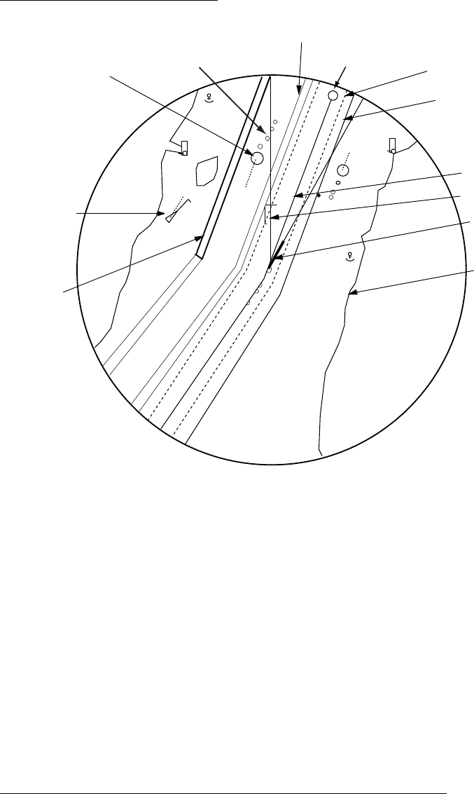
5. VIDEO PLOTTER OPERATION
5-2
Sample video plotter display
W012
Dangerous side of
own ship safe
contour may look
like this (hatched line)
Heading line
Planned route
AIS activated
target Own ship
vector
Tracked Target
(TT)
Past position
(AIS and TT)
Separation zone
Navline
Own ship
safe contour
Approximate
coastline
Waypoint
Video plotter display
5.3 Presentation Modes
Five presentation modes are available: North-up, Course-up, Head-up, Head-up
TB (True Bearing) Stern-up and North-up TM (True Motion). To select a mode,
use the [MODE] key or select the PRESENTATION MODE box then push the left
button. For a description of the presentation modes, see section 1.12.
Note 1: Chart data is not displayed on the HEAD UP and HEAD UP TB modes.
Note 2: The screen may flash when the heading is changed more than one
degree in the HEAD UP or HEAD UP TB mode.
Automatic resetting of own ship mark in true motion mode
In the true motion mode, the own ship mark is automatically returned sternward
75% from the screen center when it reaches a location 50% of the display
radius.

5. VIDEO PLOTTER OPERATION
5-3
5.4 Radar Map
A radar map is a combination of map lines and symbols whereby the user can
define and input the navigation data, route planning and monitoring data. The
radar map may contain 20,000 points of data. The map data can be saved to
facilitate repeated use on a routine navigation area. The user can create a radar
map on-real time while using the radar for navigation or at leisure time at anchor
or while the radar is not being used. Place of a map can be made for any
waterways apart from the actual own ship location.
The radar map does not affect any radar function.
5.4.1 Showing, hiding the radar map display
From menu
1. Use the trackball to select the MARK box.
2. Push the right button to open the MARK menu.
[MARK MENU]
1 ORIGIN MARK STAB
GND/SEA
2 MARK KIND
ORIGIN MARK(No. )/
ORIGIN MARK(SYM)/
MAP MARK/
WP 1~50/
WP 51~ 100/
WP 101~150/
WP 151~198/
OWN SHIP SHAPE
8 MARK POSN
CURSOR/OS/L/L
00°000.00 N
000°000.00 E
9 MAP DISPLAY
OFF/ON
0 MAP MARK COLOR*
RED/GRN/BLU/YEL/
CYA/MAG/WHT
* Not available on IMO
or A type
MARK menu
3. Select 9 MAP DISPLAY.
4. Select ON or OFF as applicable.
5. Push the right button to close the menu.
From mark legend
MARK > MAP
ON
Place cursor on text and
left-click to hide and show
map alternately.

5. VIDEO PLOTTER OPERATION
5-4
5.4.2 Inscribing radar map marks and lines
1. Use the trackball to select the MARK box at the left side of the display.
MARK >
Mark type
MARK box
2. Push the right button to open the MARK menu.
[MARK MENU]
1 ORIGIN MARK STAB
GND/SEA
2 MARK KIND
ORIGIN MARK(No. )/
ORIGIN MARK(SYM)/
MAP MARK/
WP 1~50/
WP 51~ 100/
WP 101~150/
WP 151~198/
OWN SHIP SHAPE
8 MARK POSN
CURSOR/OS/L/L
00°000.00 N
000°000.00 E
9 MAP DISPLAY
OFF/ON
0 MAP MARK COLOR*
RED/GRN/BLU/YEL/
CYA/MAG/WHT
* Not available on IMO
or A type
MARK menu
3. Select 2 MARK KIND.
4. Select MAP MARK.
Note 1: For other than IMO- and A-type radars you may specify mark color
by choosing 0 MAP MARK COLOR, pushing the scrollwheel then
choosing color desired.
Note 2: On the W-type, the indication "MAP" appears to the right of the
MARK box.
5. Push the right button to close the menu. The guidance box now reads
"MARK SELECT / MARK MENU."
6. With the cursor choosing the MARK box, use the scrollwheel to select the
mark or line type you wish to inscribe then push the left button. See the next
page for available marks. The cursor jumps into the effective display area
and the guidance box now reads "MARK / EXIT."
7. Select 8 MARK POSN.
8. Select mark entry method, CURSOR, OS or L/L. For L/L, enter position.
9. For cursor, use the trackball to put the cursor on the location desired. (You
can see the range and bearing from own ship to the cursor location by
monitoring the bearing and range indication just below the MARK box.) Push
the left button to inscribe the mark or line point.
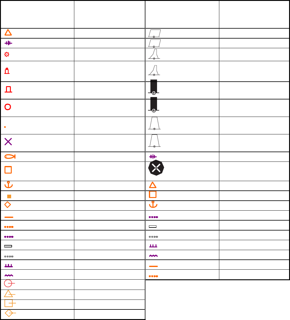
5. VIDEO PLOTTER OPERATION
5-5
• To continue entering the same mark or line (with the guidance box showing
"MARK / EXIT"), use the trackball to select location then push the left button.
• To quit entering marks or lines, push the right button when the guidance box
reads "MARK / EXIT."
B, C and W types
(seven colors
available)
Item on DISPLAY
menu* IMO and A types Item on DISPLAY
menu*
Mark Red Buoy
Danger Highlight Green Buoy
Buoy Red Buoy
Buoy Green Buoy
Buoy Red Buoy
Buoy Green Buoy
Buoy Red Buoy
Danger Highlight Green Buoy
Mark Purple Danger Highlight
Mark Purple Danger Highlight
Mark Orange Mark
Mark Orange Mark
Mark Orange Mark
Mark Purple Navline (map)
Mark White Coastline
Nav Line (map) Gray Contour Line
Coastline Purple Danger Highlight
Contour Purple (cable) Danger Highlight
Prohibited Area Orange Mark
(cable) Danger Highlight Orange Mark
(w/line) Buoy
(w/line) Mark
(w/line) Mark
(w/line) Mark
* The graphics on the DISPLAY menu can shown or hidden.
PAGE 1: 5 MARK, 8 COASTLINE, 9 CONTOUR LINE
PAGE 2: 2 NAVLINE, 3 DANGER HIGHLIGHT, 4 PROHIBITED AREA, 5 BUOY
Note: Any inscribed mark or graphic is retained when the power is turned off.

5. VIDEO PLOTTER OPERATION
5-6
5.5 Erasing Radar Map Marks and Lines
A total of 20,000 points is allotted for radar map marks and lines. When this
amount is exceeded, no more map marks or lines may be entered unless you
erase unnecessary marks or lines.
5.5.1 Erasing individual radar map marks and lines
1. With the cursor inside the effective display area, roll the scrollwheel to show
"MARK DELETE / EXIT" in the guidance box.
2. Use the trackball to put the cursor on the radar map mark or line you wish to
erase.
3. Push the left button to erase selected mark or line.
Note: When erasing a line, the cursor location determines how the line will
be erased. To erase a single line segment, put the cursor on the
starting point of the line. When the junction point between two line
segments is erased, the line is redrawn connecting the line segments
that were before and after the erased junction. See the figure below for
an example.
Erasing two lines
Erasing a line segment
After erasing
After erasing
Cursor location and line processing

5. VIDEO PLOTTER OPERATION
5-7
5.5.2 Erasing all radar map marks and lines
You can erase all radar map marks and lines from the screen as below. Be
absolutely sure you want to erase all map marks and lines – erased marks and
lines cannot be restored.
1. Left-click the MENU box to open the menu.
2. Select 5 [PLOTTER] to open the PLOTTER menu.
3. Select 8 [DATA ERASE].
*
1
Colors not shown on IMO type
*
2
Not available on IMO type
*
3
Not available on IMO or A type
[DATA ERASE]
1BACK
2 OWN TRACK*
1
RED/GRN/BLU/YEL/
CYA/MAG/WHT/
30%/50%/80%/ALL
3 TARGET TRACK*
2
RED/GRN/BLU/YEL/
CYA/MAG/WHT/
30%/50%/80%/ALL
4 MARK ALL ERASE
NO/YES
5 WPT ALL ERASE
NO/YES
6 NAV LINE ALL ERASE
NO/YES
7 OWN TRACK DELETE*
3
2POINTS/AREA
8 TARGET TRACK DELETE*
3
2POINTS/AREA
DATA ERASE menu
4. Select 4 MARK ALL ERASE.
5. Select YES to erase all marks.
6. Push the right button three times to close the menu.

5. VIDEO PLOTTER OPERATION
5-8
5.6 Radar Map Corrections
5.6.1 Radar map correction
When there is positional error between the radar screen and radar map marks
and lines, do the following to correct it.
1. With the cursor inside the effective display area, roll the scrollwheel to
display "CHART ALIGN L=OFF / EXIT" in the guidance box.
2. Operate the trackball to align the radar map with the radar screen.
3. Push the left button to set. "MAN ALIGNED" appears at the right side of the
screen.
To release the radar map correction, display "CHART ALIGN L=OFF / EXIT"
in the guidance box then push the left button until "MAN ALIGNED" disappears
from the screen.
5.6.2 Cursor data correction
You can correct cursor data as below.
1. Left-click the MENU box to open the menu.
2. Select 5 [PLOTTER] to open the PLOTTER menu.
[PLOTTER]
1 BACK
2 CHART COLOR*
GRN/YEL/CYA
ORANGE/GRAY
3 OWN TRACK INTERVAL
OFF/DRAW/10S/30S/
1M/2M/3M/6M/15M
4 OWN TRACK COLOR*
RED/GRN/BLU/YEL/
CYA/MAG/WHT
5 TGT TRACK INTERVAL*
OFF/DRAW/10S/30S/
1M/2M/3M/6M/15M
6 TGT TRACK COLOR*
RED/GRN/BLU/YEL/
CYA/MAG/WHT
7 CURSOR L/L ALIGN
OFF/ON
8 [DATA ERASE]
9 [DISPLAY]
0 AUTO TARGET TRACK*
OFF/ON * Not available on IMO type
PLOTTER menu
3. Select 7 CURSOR L/L ALIGN.
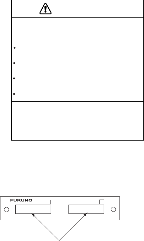
5. VIDEO PLOTTER OPERATION
5-9
4. Select ON. "ALIGN" appears (in light blue) next to cursor position in the text
area if chart alignment has been done. To remove the correction, select OFF.
If you are using the AIS function, select ON.
5. Push the right button twice to close the menu.
5.7 Chart Cards (A, B, C and W types)
FURUNO or NAVIONICS charts can be overlaid on the radar image when they
are interfaced with the optional Card I/F Unit CU-200.
CAUTION
Handle chart cards and memory cards
with care.
Keep cards away from direct sunlight,
heat sources, and active gases.
Keep cards away from water and
chemicals.
Keep the connector free foreign
material.
Do not drop the cards.
Chart cards are intended as an aid to
navigation. The navigator has the
responsibility to check all aids available
to confirm position.
5.7.1 Displaying a chart
To display a chart:
1. Insert a chart card in either of the two card slots in the Card I/F Unit CU-200.
Card Slot
++
12
Card slot location
2. Press the [POWER] button on the control unit to turn the power on. With the
radar transmitting, select the radar display (NU, CU, TM modes only) or the
radar/video plotter display to display the chart.
To display a chart after the power has been turned on, change the range by
pressing the [RANGE+] or [RANGE-] key or operating the RANGE box.

5. VIDEO PLOTTER OPERATION
5-10
5.7.2 Chart position correction
There may be a case where the chart overlay is not aligned with the radar image.
This is due to an error in the position fixing system (GPS, Loran, etc.) or the
different coordinates between the position fixing system and the radar. In this
case, align the chart with the radar image as below.
1. With the cursor inside the effective display area, roll the scrollwheel to display
"CHART ALIGN L=OFF / EXIT" in the guidance box.
2. Operate the trackball to align the chart with the radar map. Note that track is
neither recorded nor displayed at this point.
3. Push the left button to set. "CHART ALIGN" appears (in red) at the right side
of the screen.
To release the chart position correction, display "CHART ALIGN L=OFF /
EXIT" in the guidance box then push the left button until "CHART ALIGN"
disappears from the screen.
5.7.3 Correcting cursor data
1. Left-click the MENU box to open the menu.
2. Select 5 [PLOTTER] to open the PLOTTER menu.
[PLOTTER]
1 BACK
2 CHART COLOR*
GRN/YEL/CYA
ORANGE/GRAY
3 OWN TRACK INTERVAL
OFF/DRAW/10S/30S/
1M/2M/3M/6M/15M
4 OWN TRACK COLOR*
RED/GRN/BLU/YEL/
CYA/MAG/WHT
5 TGT TRACK INTERVAL*
OFF/DRAW/10S/30S/
1M/2M/3M/6M/15M
6 TGT TRACK COLOR*
RED/GRN/BLU/YEL/
CYA/MAG/WHT
7 CURSOR L/L ALIGN
OFF/ON
8 [DATA ERASE]
9 [DISPLAY]
0 AUTO TARGET TRACK*
OFF/ON * Not available on IMO type
PLOTTER menu
3. Select 7 CURSOR L/L ALIGN.
4. Select ON. "ALIGN" appears (in red) next to cursor position in the cursor data
box. (To remove the correction, select OFF. If you are using the AIS function,
select ON.)
5. Push the right button twice to close the menu.

5. VIDEO PLOTTER OPERATION
5
-
11
5.7.4 Chart land color (B, C and W types)
You may select the color for the land on charts as follows:
1. Left-click the MENU box to open the menu.
2. Select 5 [PLOTTER] to open the PLOTTER menu.
[PLOTTER]
1 BACK
2 CHART COLOR*
GRN/YEL/CYA
ORANGE/GRAY
3 OWN TRACK INTERVAL
OFF/DRAW/10S/30S/
1M/2M/3M/6M/15M
4 OWN TRACK COLOR*
RED/GRN/BLU/YEL/
CYA/MAG/WHT
5 TGT TRACK INTERVAL*
OFF/DRAW/10S/30S/
1M/2M/3M/6M/15M
6 TGT TRACK COLOR*
RED/GRN/BLU/YEL/
CYA/MAG/WHT
7 CURSOR L/L ALIGN
OFF/ON
8 [DATA ERASE]
9 [DISPLAY]
0 AUTO TARGET TRACK*
OFF/ON * Not available on IMO type
PLOTTER menu
3. Select 2 CHART COLOR.
4. Select color desired.
5. Push the right button twice to close the menu.
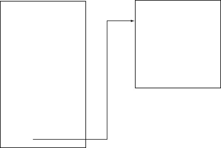
5. VIDEO PLOTTER OPERATION
5-12
5.8 Hiding, Showing Graphics on the Video Plotter
Display
1. Left-click the MENU box to open the menu.
2. Select 5 [PLOTTER] to open the PLOTTER menu.
3. Select 9 [DISPLAY]. Select an item. To go to page 2, select 0 NEXT. You may
return to page 1 by choosing 1 BACK and pressing the scrollwheel or the left
button.
Page 1
Page 2
Choose
0 NEXT
to show
page 2.
* Not available on IMO or A type
[DISPLAY (1/2)]
1BACK
2 GRID
OFF/ L/L
3 OWN TRACK
OFF/ON
4 TARGET TRACK*
OFF/ON
5 MARK
OFF/ON
6 LAND DENSITY*
OFF/ON
7 PLACE NAME*
OFF/ON
8 COAST LINE
OFF/ON
9 CONTOUR LINE
OFF/ON/DEPTH
0 NEXT
[DISPLAY (2/2)]
1BACK
2 NAV LINE(MAP)
OFF/ON
3 DANGER HIGHLIGHT
OFF/ON
4 PROHIBITED AREA
OFF/ON
5 BUOY
OFF/ON
DISPLAY menus
4. Push the scrollwheel to select OFF or ON.
Note: LAND DENSITY fills (ON) or hollows (OFF) land on an electronic
chart. Land will be hollow when wrong card or wrong scale is used,
regardless of LAND DENSITY setting.
5. Repeat steps 3 and 4 to set other items.
6. Push the right button three or four times to close the menu depending on
which page of the DISPLAY menu you are using.
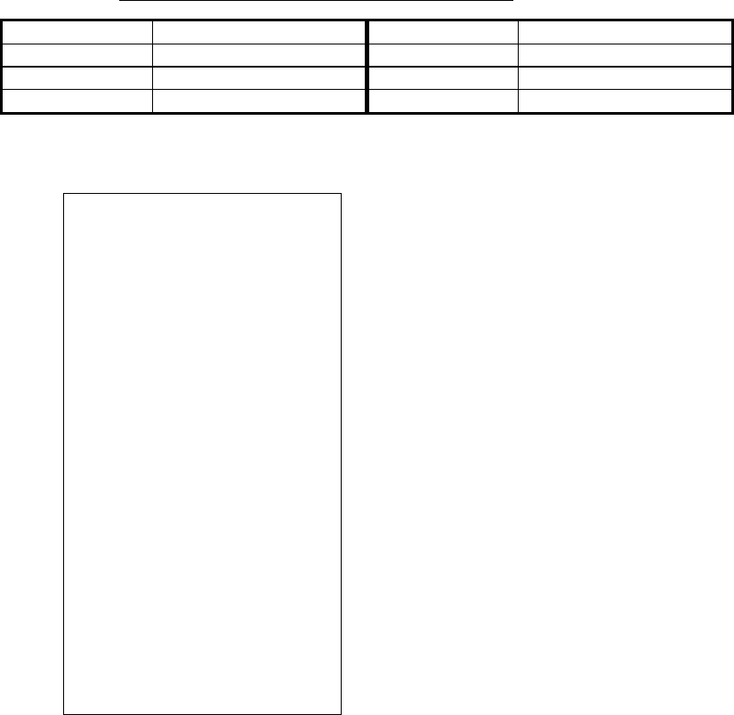
5. VIDEO PLOTTER OPERATION
5-13
5.9 Track
5.9.1 Plotting own ship’s track
A total of 20,000 points are allotted for storage of own ship’s track, marks and
lines. When this memory becomes full, the oldest track is deleted to make room
for the latest. For that reason you may want to adjust the recording interval to
conserve the memory.
The table below shows the relation between plotting interval and maximum track
recording time.
Own track plotting interval and storage time
Interval Max. Recording Time Interval Max. Recording Time
10 s 55 hr 30 min 2 min 27 days 18 hr 40 min
30 s 166 hr 40 min 3 min 41 days 16 hr
1 min 13 days 21 hr 20 min 6 min 83 days 8 hr
1. Left-click the MENU box to open the menu.
2. Select 5 [PLOTTER] to open the PLOTTER menu.
[PLOTTER]
1 BACK
2 CHART COLOR*
GRN/YEL/CYA
ORANGE/GRAY
3 OWN TRACK INTERVAL
OFF/DRAW/10S/30S/
1M/2M/3M/6M/15M
4 OWN TRACK COLOR
RED/GRN/BLU/YEL/
CYA/MAG/WHT
5 TGT TRACK INTERVAL*
OFF/DRAW/10S/30S/
1M/2M/3M/6M/15M
6 TGT TRACK COLOR*
RED/GRN/BLU/YEL/
CYA/MAG/WHT
7 CURSOR L/L ALIGN
OFF/ON
8 [DATA ERASE]
9 [DISPLAY]
0 AUTO TARGET TRACK*
OFF/ON * Not available on IMO type
PLOTTER menu
3. Select 3 OWN TRACK INTERVAL.
4. Select appropriate option. Select OFF to stop plotting own ship’s track.
DRAW displays the track but does not record it. Track is erased when the
power is turned off or the range is changed.
5. Push the right button twice to close the menu.

5. VIDEO PLOTTER OPERATION
5-14
5.9.2 Plotting interval for other ships' tracks (A, B, C and W types)
The tracks of 15 targets (other ships) can be recorded. The memory capacity for
other ships’ track is 15,000 points (1,000 points per each of 15 targets). When
the other ships’ track memory becomes full the oldest track is deleted to make
room for the latest. For that reason you may want to adjust the recording interval
to conserve the memory.
The table below shows the relation between plotting interval and maximum track
recording time for other ships’ track.
Other target plot interval and storage time
Interval Max. Recording Time Interval Max. Recording Time
10 s 2 hrs 46 min 2 min 66 hrs 20 min
30 s 8 hrs 20 min 3 min 50 hrs
1 min 16 hrs 40 min 6 min 100 hrs
1. Left-click the MENU box to open the menu.
2. Select 5 [PLOTTER] to open the PLOTTER menu.
3. Select 5 TGT TRACK INTERVAL.
4. Select appropriate option. Select OFF to stop plotting own ship’s track.
DRAW displays the track but does not record it.
5. Push the right button twice to close the menu.
5. VIDEO PLOTTER OPERATION
5-15
5.9.3 Auto target track (A, B, C and W types)
You may display the track for up to 15 targets, automatically or manually.
1. Left-click the MENU box to open the menu.
2. Select 5 [PLOTTER] to open the PLOTTER menu.
3. Select 0 AUTO TARGET TRACK.
4. Select OFF or ON as appropriate.
ON: TT target number (1-15) automatically assigned to corresponding ship's
track on the plotter display.
OFF: The operator manually assigns target numbers to TT and AIS targets.
5. Push the right button twice to close the menu. If you selected OFF at step 4,
go to step 6 to assign a number to a track.
6. Put the cursor inside the effective display then spin the scrollwheel to show
TARGET TRACK ON/EXIT in the guidance area.
7. Select the track of the TT or AIS target for which to assign target number
then push the left button.
8. Repeat step 7 to assign target numbers to other tracked targets, up to 15
targets.
9. Push the right button to finish.
5.9.4 Choosing track color (A, B, C and W types)
1. Left-click the MENU box to open the menu.
2. Select 5 [PLOTTER] to open the PLOTTER menu.
3. Select 4 OWN TRACK COLOR or 6 TGT TRACK COLOR, whichever track
color you want to set.
4. Select color desired.
5. Push the right button twice to close the menu.

5. VIDEO PLOTTER OPERATION
5-16
5.9.5 Erasing track from the menu, on the screen
The display may become full of track when, for example, own ship traces the
same route several times or there are many tracks from other ships. You may
erase track two ways: through the menu (by color or percentage) or directly on
the screen (track between specified points is erased).
Erasing track from the menu
1. Left-click the MENU box to open the menu.
2. Select 5 [PLOTTER] to open the PLOTTER menu.
3. Select 8 [DATA ERASE].
*
1
Colors not shown on IMO type
*
2
Not available on IMO type
*
3
Not available on IMO or A type
[DATA ERASE]
1BACK
2 OWN TRACK*
1
RED/GRN/BLU/YEL/
CYA/MAG/WHT/
30%/50%/80%/ALL
3 TARGET TRACK*
2
RED/GRN/BLU/YEL/
CYA/MAG/WHT/
30%/50%/80%/ALL
4 MARK ALL ERASE
NO/YES
5 WPT ALL ERASE
NO/YES
6 NAV LINE ALL ERASE
NO/YES
7 OWN TRACK DELETE*
3
2POINTS/AREA
8 TARGET TRACK DELETE*
3
2POINTS/AREA
DATA ERASE menu
4. Select 2 OWN TRACK or 3 TARGET TRACK (not available on IMO-type
radar), whichever track you want to erase.
5. Select color (not available on IMO type) or percentage to erase. For example,
"30" erases the oldest 30% of the track selected at step 4. Select "ALL" to
erase all of the corresponding track.
6. Push the right button three times close the menu.
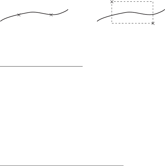
5. VIDEO PLOTTER OPERATION
5-17
5.9.6 Erasing track with the cursor
You may erase own ship track or any target’s track directly on the screen, by two
points or area. Select the erasure method and then erase track.
Erase track between two points
x: Specified point
Erase track within a specific range
Choosing erasure method
1. Left-click the MENU box.
2. Select 5 [PLOTTER] and push the left button.
3. Select 8 [DATA ERASE] and push the left button.
4. Select 7 OWN TRACK DELETE and push the left button.
5. Select 2POINTS or AREA as appropriate and push the left button.
2POINTS: Erase track between two points
AREA: Erase all track within an area
6. Select appropriate option for 8 TARGET TRACK DELETE similarly.
7. Push the right button three times to close the menu.
Erasing track between two points, area
1. Place the cursor inside the effective display area.
2. Spin the scrollwheel to show OWN TRACK DELETE/EXIT or TGT TRACK
DELETE/EXIT in the guidance box at the bottom right-hand corner on the
screen, whichever track you want to erase.
3. Use the trackball to place the cursor at the top-left corner of the area (or 1st
point in case of erasure by two points) and push the left button.
4. Use the trackball to drag the cursor at the bottom-right corner of the area (or
2nd point in case of erasure by two points). If the erasure method (chosen on
the previous page) is "AREA", a rectangle appears when you start dragging
the cursor.
5. Push the left button to erase track.
6. Push the right button to quit.
Note that this function is automatically canceled if there is no erasure occurring
in 30 seconds.
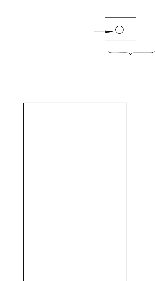
5. VIDEO PLOTTER OPERATION
5-18
5.10 Waypoints
A particular location is known as a "waypoint," whether it be a starting point, a
destination point or an intermediate point on a voyage. This unit can store 200
waypoints, numbered 001 to 200. Waypoints may be entered with the cursor, by
manual input of latitude and longitude and at current position.
5.10.1 Entering waypoints
Entering waypoints with the cursor
1. Use the trackball to select the MARK box at the left side of the screen.
MARK >
Mark type last
selected, mark
number
162.5°T 11.7
NM
Bearing and range from
own ship to waypoint
1
MARK box
2. Push the right button to open the MARK menu.
[MARK MENU]
1 ORIGIN MARK STAB
GND/SEA
2 MARK KIND
ORIGIN MARK(No. )/
ORIGIN MARK(SYM)/
MAP MARK/
WP 1~50/
WP 51~ 100/
WP 101~150/
WP 151~198/
OWN SHIP SHAPE
8 MARK POSN
CURSOR/OS/L/L
00°000.00 N
000°000.00 E
9 MAP DISPLAY
OFF/ON
0 MAP MARK COLOR*
RED/GRN/BLU/YEL/
CYA/MAG/WHT
* Not available on IMO
or A type
MARK menu
3. Select 2 MARK KIND.
4. Select the WPT item which best matches the waypoint number you wish to
enter. For example, if you want to enter waypoint number 59, select "WPT
51-100."
5. Push the right button to close the menu. The guidance box now reads
"MARK SELECT / MARK MENU."

5. VIDEO PLOTTER OPERATION
5-19
[NAV LINE•WPT (1/2)]
1 BACK
2 NAV LINE DATA
OFF/EXT DATA/
INTERNAL DATA/
WPT MARK*
3 NAV LINE SELECT
- -
FORWARD/REVERSE
4 SKIP NEXT WPT
5 NAV LINE WIDTH
9.99NM
6 [WPT SET]
7 [WPT LIST]
8 [NAV LINE SET]
9 [NAV LINE LIST]
0 NEXT
[WPT SET]
1 BACK
2 WPT NO. SELECT
001
3 WPT NAME
4 WPT L/L
_ _°_ _._ _ _ N
_ _ _°_ _. _ _ _E
5 CLEAR DATA
NO/YES
6. With the MARK box selected, roll the scrollwheel to display waypoint number
desired then push the left button. The cursor jumps into the effective display
area and the guidance box reads "MARK / EXIT."
7. Use the trackball to put the cursor where you want to inscribe a waypoint
mark then push the left button to inscribe the mark. The waypoint mark (" " +
waypoint number) appears at the location selected. (You can see the range
and bearing to the cursor location by monitoring the mark range and bearing
indication just below the MARK box.)
• To enter another waypoint, push the right button when the guidance box reads
"MARK / EXIT" then repeat steps 6-8. ("WPT" should be selected on the
MARK menu.)
• To quit entering waypoints, push the right button when the guidance box reads
"MARK / EXIT."
Entering waypoints by manual input of latitude and longitude
1. Left-click the MENU box to open the menu.
2. Select 8 [NAV LINE•WPT].
* Not available on IMO type
NAV LINE•WPT menu
3. Select 6 [WPT SET].
WPT SET menu
5. VIDEO PLOTTER OPERATION
5-20
4. Select 2 WPT NO. SELECT.
5. Use the scrollwheel to select waypoint number: Select location then push the
scrollwheel to set.
6. To enter waypoint name, follow the procedure below. If you do not require
waypoint name go to step 7.
e) Select 3 WPT NAME.
f) Select alphanumeric character desired then push the scrollwheel.
g) Repeat step 2 to complete the waypoint name. You may use up to 15
alphanumeric characters for waypoint name.
7. Select 4 WPT L/L.
8. Enter latitude and longitude position as follows:
a) Select location desired then push the scrollwheel. (The scrollwheel may be
pushed again to skip a place.) For input by keyboard, press appropriate
numeric keys then press the [ENTER MARK] key.
b) To switch co-ordinate polarity, roll the scrollwheel or use the [2] key in case
of keyboard operation.
9. To enter another waypoint, repeat steps 4-8.
10. Push the right button three times to close the menu.
5.10.2 Editing, erasing waypoints from the menu
You may edit or erase waypoints from the menu as follows. You cannot erase or
edit a waypoint that is part of a route that is currently in use.
1. Left-click the MENU box to open the menu.
2. Select 8 [NAV LINE•WPT].
3. Select 6 [WPT SET].
4. Select 2 WPT NO. SELECT.
5. Use the scrollwheel to enter waypoint number you wish to edit. Then, do one
of the following:
• To change the waypoint name, Select 3 WPT NAME. Use the scrollwheel
to edit waypoint name.
• To edit the waypoint position, Select 4 WPT L/L. Use the scrollwheel to edit
waypoint position.
• To erase the waypoint, Select 5 CLEAR DATA. Note that a waypoint cannot
be erased if it is part of a nav line.
6. Push the right button three times to close the menu.

5. VIDEO PLOTTER OPERATION
5-21
5.10.3 Erasing waypoints
Waypoints may be erased individually or collectively. Note that a waypoint
cannot be erased if it is part of a nav line.
Erasing individual waypoints
1. With the cursor inside the effective display area, roll the scrollwheel to display
"MARK DELETE / EXIT" in the guidance box.
2. Use the trackball to put the cursor on the waypoint you wish to erase. A
flashing "+" appears on the mark when it is correctly selected.
3. Push the left button or the scrollwheel to erase the waypoint.
4. To erase another waypoint, repeat steps 2 and 3.
5. To finish, push the right button when the guidance reads "MARK DELETE /
EXIT".
Erasing all waypoints
1. Left-click the MENU box to open the menu.
2. Select 5 [PLOTTER] to open the PLOTTER menu.
3. Select 8 [DATA ERASE].
*
1
Colors not shown on IMO type
*
2
Not available on IMO type
*
3
Not available on IMO or A type
[DATA ERASE]
1BACK
2 OWN TRACK*
1
RED/GRN/BLU/YEL/
CYA/MAG/WHT/
30%/50%/80%/ALL
3 TARGET TRACK*
2
RED/GRN/BLU/YEL/
CYA/MAG/WHT/
30%/50%/80%/ALL
4 MARK ALL ERASE
NO/YES
5 WPT ALL ERASE
NO/YES
6 NAV LINE ALL ERASE
NO/YES
7 OWN TRACK DELETE*
3
2POINTS/AREA
8 TARGET TRACK DELETE*
3
2POINTS/AREA
DATA ERASE menu
4. Select 5 WPT ALL ERASE.
5. Select YES to erase all waypoints.
6. Push the right button three times to close the menu.

5. VIDEO PLOTTER OPERATION
5-22
[WPT LIST (1/25)]
1 BACK (L=TOP)
001 WP1
34°42.110 N
136°31.580 E
002 WP2
33°97.690 N
134°64.350 E
003
004
005
006
007
008
0 NEXT (L=LAST)
5.10.4 Waypoint list
The waypoint list stores position data of all registered waypoints. Each page of
the waypoint list holds eight waypoints.
To display the waypoint list:
1. Right-click the MENU box at the right side of the screen to open the menu.
2. Select 8 [NAV LINE•WPT] to open the NAV LINE•WPT menu.
3. Select 7 [WPT LIST]. Asterisks indicate no data.
WPT list
4. To go to a next page, select 0 NEXT.
5. Push the right button several times to close the waypoint list and the menu.

5. VIDEO PLOTTER OPERATION
5-23
[NAV LINE•WPT (2/2)]
1 BACK
2 ARRIVAL WPT ALARM
OFF/ON
3 TURNING LINE
OFF/ON/REVISED
4 DISP WPT NO.
OFF/ON
5 DISP WPT NAME
OFF/ON
5.10.5 Displaying waypoint name and number
You may turn waypoint name and number display on or off as desired.
1. Left-click the MENU box to open the menu.
2. Select 8 [NAV LINE•WPT].
3. Select 0 NEXT.
NAV LINE•WPT menu (2/2)
4. Select 4 DISP WPT NO..
5. Select OFF or ON as appropriate.
6. Select 5 DISP WPT NAME.
7. Select OFF or ON as appropriate.
8. Push the right button three times to close the menu.

5. VIDEO PLOTTER OPERATION
5-24
[NAV LINE SET]
1 BACK
2 NAV LINE NO. SELECT
01
3 NAV LINE NAME
4 NAV LINE ENTRY
— — —
— — —
— — —
— — —
— — —
— — —
— — —
— — —
— — —
— — —
5 CLEAR DATA
NO/YES
5.11 Nav Lines
30 nav lines may be entered, and each line may have up to 30 waypoints.
5.11.1 Entering a new nav line
To enter a nav line, first enter appropriate waypoints. Then, do the following:
1. Left-click the MENU box to open the menu.
2. Select 8 [NAV LINE•WPT].
3. Select 8 [NAV LINE SET].
NAV LINE SET menu
4. Select 2 NAV LINE NO. SELECT.
5. Use the scrollwheel to enter nav line no., in two digits.
6. Select 3 NAV LINE NAME.
7. Use the scrollwheel to enter a name.
8. Select 4 NAV LINE ENTRY.
9. Use the scrollwheel to enter waypoint numbers (in three digits): Select
numeral and push it to set.
10. To enter another nav line, select 0 BACK to return to the NAV LINE SET
menu then repeat steps 4-9.
11. To finish, push the right button several times to close the menu.
5. VIDEO PLOTTER OPERATION
5-25
5.11.2 Editing a nav line
Follow the procedure below to edit a nav line. Before editing a nav line it must be
disabled. See section 5.11.6.
1. Left-click the MENU box to open the menu.
2. Select 8 [NAV LINE•WPT].
3. Select 8 [NAV LINE SET].
4. Select 2 NAV LINE NO. SELECT.
5. Use the scrollwheel to enter nav line number to edit.
6. To edit nav line name, Select 3 NAV LINE NAME. Use the scrollwheel to
change name.
7. To replace waypoints in a nav line, do the following:
1) Select 4 [NAV DATA ENTRY].
2) Push the scrollwheel to select the waypoint you wish to replace.
3) Roll the scrollwheel to set new waypoint number. To delete the waypoint from
the nav line, enter "000".
4) Push the scrollwheel to finish.
8. Push the right button several times to close the menu.

5. VIDEO PLOTTER OPERATION
5-26
[NAV LINE LIST (1/30)]
1 BACK (L=TOP)
01 LINE 1
001—002—003
004—005—006
— — —
— — —
— — —
— — —
— — —
— — —
— — —
— — —
0 NEXT (L=LAST)
5.11.3 Nav line list
The nav line list, which shows all nav lines registered, may be displayed as
follows:
1. Left-click the MENU box to open the menu.
2. Select 8 [NAV LINE•WPT].
3. Select 9 [NAV LINE LIST].
NAV LINE LIST
4. To go to a next page select 0 NEXT. To return to a previous page, select 1
BACK.
5. Push the right button as many times as necessary to close the menu.

5. VIDEO PLOTTER OPERATION
5-27
[NAV LINE SET]
1 BACK
2 NAV LINE NO. SELECT
01
3 NAV LINE NAME
4 NAV LINE ENTRY
— — —
— — —
— — —
— — —
— — —
— — —
— — —
— — —
— — —
— — —
5 CLEAR DATA
NO/YES
5.11.4 Erasing a nav line
30 nav lines may be entered. You may erase unnecessary nav lines as shown
below. A nav line that is currently in use cannot be erased.
Erasing individual nav lines
1. Left-click the MENU box to open the menu.
2. Select 8 [NAV LINE•WPT].
3. Select 8 [NAV LINE SET].
NAV LINE SET menu
4. Select 2 NAV LINE NO. SELECT.
5. Use the scrollwheel to enter nav line no., in two digits.
6. Select 5 CLEAR DATA.
7. Push the scrollwheel or the left button to delete the nav line.
8. Push the right button three times to close the menu.

5. VIDEO PLOTTER OPERATION
5-28
[NAV LINE•WPT (1/2)]
1 BACK
2 NAV LINE DATA
OFF/EXT DATA/
INTERNAL DATA/
WPT MARK*
3 NAV LINE SELECT
- -
FORWARD/REVERSE
4 SKIP NEXT WPT
5 NAV LINE WIDTH
0.00NM
6 [WPT SET]
7 [WPT LIST]
8 [NAV LINE SET]
9 [NAV LINE LIST]
0 NEXT
Erasing all nav lines
1. Left-click the MENU box.
2. Select 5 [PLOTTER].
3. Select 8 [DATA ERASE].
*
1
Colors not shown on IMO type
*
2
Not available on IMO type
*
3
Not available on IMO or A type
[DATA ERASE]
1BACK
2 OWN TRACK*
1
RED/GRN/BLU/YEL/
CYA/MAG/WHT/
30%/50%/80%/ALL
3 TARGET TRACK*
2
RED/GRN/BLU/YEL/
CYA/MAG/WHT/
30%/50%/80%/ALL
4 MARK ALL ERASE
NO/YES
5 WPT ALL ERASE
NO/YES
6 NAV LINE ALL ERASE
NO/YES
7 OWN TRACK DELETE*
3
2POINTS/AREA
8 TARGET TRACK DELETE*
3
2POINTS/AREA
DATA ERASE menu
4. Select 6 NAV LINE ALL ERASE.
5. Select YES to erase all nav lines and their data.
6. Push the right button three times to close the menu.
5.11.5 Setting up nav lines
Nav lines can be set up as follows:
1. Left-click the MENU box.
2. Select 8 [NAV LINE•WPT].
3. Select 2 NAV LINE DATA.
4. Select INTERNAL DATA.
5. Select 5 NAV LINE WIDTH.
6. Use the scrollwheel to enter the width for the
nav line, from 0.0-9.99(nm). A pair of orange
lines mark the width of the nav line.
* Not available on IMO type
NAV LINE•WPT menu (1/2)
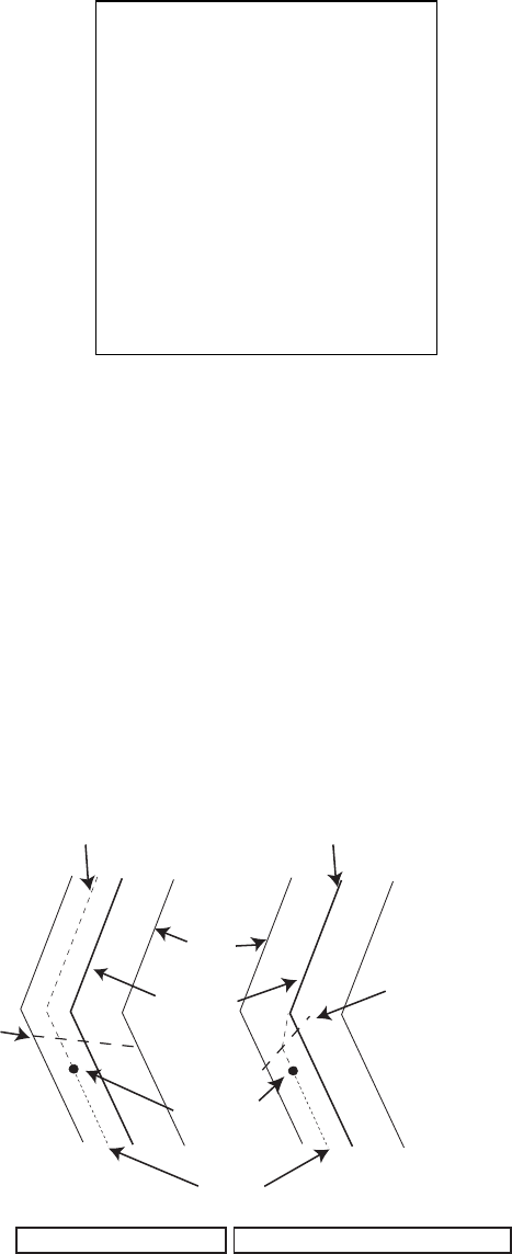
5. VIDEO PLOTTER OPERATION
5-29
[NAV LINE•WPT (2/2)]
1 BACK
2 ARRIVAL WPT ALARM
OFF/ON
0.19NM
3 TURNING LINE
OFF/ON/REVISED
4 DISP WPT NO.
OFF/ON
5 DISP WPT NAME
OFF/ON
7. If you want to be alerted when own ship nears a waypoint by a preset
distance, select 0 NEXT then push the scrollwheel.
NAV LINE•WPT menu (2/2)
8. Select ARRIVAL WPT ALARM.
9. Select ON.
10. Select 3 TURNING LINE.
11. Select appropriate option.
OFF: Turns turning lines off.
ON: Use this setting when the vessel is not to correct cross track error to return
to course set, after arriving at turning line location.
REVISED: Use this setting when vessel is to return to course set after correcting
cross track error, after arriving at turning line location.
Note: Before using the turning line feature, set the Trial Maneuver function as
appropriate, on the TT●AIS menu.
Own ship
Turning line
Course
Nav
line
Track
Turning line
TURNING LINE: REVISED
TURNING LINE: ON
No cross track error
correction at turning line
Cross track error
correction at turning line
Turning line
12. Push the right button three times to close the menu.

5. VIDEO PLOTTER OPERATION
5-30
5.11.6 Displaying nav line, waypoint mark
Displaying internal nav lines
1. Left-click the MENU box to open the menu.
2. Select 8 [NAV LINE•WPT].
3. Select 2 NAV LINE DATA.
4. Select INTERNAL DATA.
5. Select 3 NAV LINE SELECT.
6. Use the scrollwheel to enter the nav line number you want to display. Select
numeral and push it to set. Note that the same nav line no. cannot be
entered more than once.
7. Use FORWARD or REVERSE to select the order to display waypoints on the
nav line. FORWARD to display them in original order or REVERSE to display
them in reverse order. Select appropriate option then push the scrollwheel.
8. To skip the next waypoint, Select 2 SKIP NEXT WPT.
9. Push the right button twice to close the menu.
Displaying external nav lines
Nav lines from an external navigator can be displayed as below. RTE and WPL
sentences are necessary to display a nav line from a navigator.
1. Left-click the MENU box to open the menu.
2. Select 8 [NAV LINE•WPT].
3. Select 2 NAV LINE DATA.
4. Select EXT DATA.
5. Do the following as appropriate:
1) Set width (0.0-9.9 nm) of the nav line with 5 NAV LINE WIDTH.
2) Turn waypoint number display on or off with 4 DSP WPT NO (page 2 of NAV
LINE•WPT menu).
3) Set turning line with 3 TURNING LINE (page 2 of NAV LINE•WPT menu).
6. Push the right button two or three times depending on which page of the NAV
LINE•WPT menu you are using.
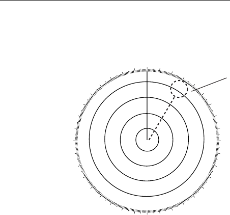
5. VIDEO PLOTTER OPERATION
5-31
Waypoint mark (A, B, C and W types only)
The waypoint mark shows the location of a destination waypoint that is set on a
navigator. You may mark this location on the radar display by following the
procedure shown below.
000 010 020 030
040
050
060
070
080
090
100
110
120
130
140
150
160
170
180
190
200
210
220
230
240
250
260
270
280
290
300
310
320
330 340 350
Waypoint Mark
Waypoint mark
1. Left-click the MENU box to open the menu.
2. Select 8 [NAV LINE•WPT].
3. Select 2 NAV LINE DATA.
4. Select WPT MARK.
5. Push the right button twice to close the menu.
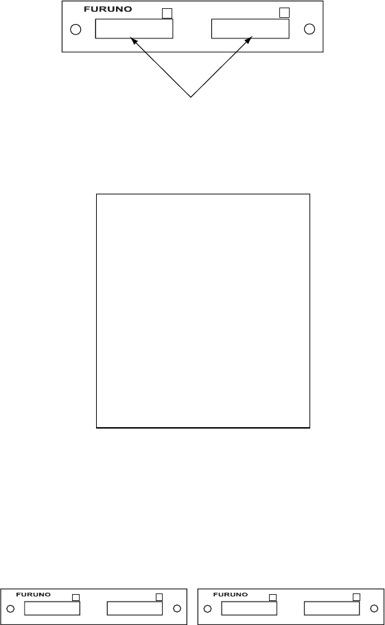
5. VIDEO PLOTTER OPERATION
5-32
[CARD (1/2)]
1 BACK
2 DRIVE SELECT
A/B/C/D*
3 [READ CARD]
4 [WR MARK]
5 [WR NAV LINE•WPT]
6 [WR OWN TRACK]
7 [WR TARGET TRACK]**
8 [WR SETTING DATA]
9 [WR INSTALL DATA]
0 NEXT
5.12 Recording Data
The optional Card I/F Unit CU-200 is required to record or replay data. The
CU-200 has two card slots and you can connect two units, for a total of four card
slots.
5.12.1 Initializing memory (RAM) cards
Before you can use a memory (RAM) card it must be initialized. Formatting
prepares the recording surface of the card for use with the system, and deletes
all data recorded in the memory card. You can format cards you’ve used before,
however, in which case all prior information on them is erased.
1. Insert a blank memory card into the appropriate card slot in the Card I/F Unit.
Card Slot
++
12
Card I/F unit, front view
2. Left-click the MENU box to open the menu.
3. Select 6 [CARD]. (Note that "WR" in the CARD menu means "Write.")
CARD menu, page 1
4. Select 2 DRIVE SELECT.
5. Select appropriate drive.
Note: If one unit is connected the drives are, from the left drive on the unit,
A=1 and B=2. In case of a second drive unit, its drives are, from the
left drive on the unit, C=1 and D=2.
++
12
++
12
A B C D
One Unit 2nd Unit
* Drives available are shown.
** Not available on IMO type

5. VIDEO PLOTTER OPERATION
5-33
[CARD (1/2)]
1 BACK
2 DRIVE SELECT
A/B/C/D*
3 [READ CARD]
4 [WR MARK]
5 [WR NAV LINE•WPT]
6 [WR OWN TRACK]
7 [WR TARGET TRACK]**
8 [WR SETTING DATA]
9 [WR INSTALL DATA]
0 NEXT
6. Select 0 NEXT.
CARD menu, page 2
7. Select 3 CARD INITIALIZE.
CARD INITIALIZE menu
8. Select 2 INITIALIZE START to initialize the card. The LED near the card
flashes, the CARD menu disappears and the message "FORMAT CARD
DATA" appears.
5.12.2 Recording data
When the memory becomes full, the oldest track is erased to make room for the
latest. Further, when the memory is full you cannot enter another mark or line
unless you erase unnecessary marks, lines or track. Thus you should save
important data to a memory card so as not to lose important data.
1. Insert initialized memory card into appropriate drive in Card I/F Unit.
2. Left-click the MENU box to open the menu.
3. Select 6 [CARD].
CARD menu
[CARD (2/2)]
1 BACK
2 [FILE DELETE]
3 [CARD INITIALIZE]
[CARD INITIALIZE]
1 BACK
2 INITIALIZE START
NO/YES
* Drives available are shown.
** Not available on IMO type

5. VIDEO PLOTTER OPERATION
5-34
4. Select DRIVE SELECT.
5. Select appropriate drive.
6. Select data to record (one item among 4-9). For example select 4 WR MARK.
The display then looks something like the one below.
CARD WRITE menu
Note: The file name is composed of a single alphabet, the file type, and
seven alphanumeric characters, the file number. The file type is
denoted as follows:
M: Radar map mark (20,000 points)
W: Waypoint, nav line (Waypoint, 20 points, nav line, 30 lines)
T: Own track (20,000 points)
A: Target track (1,000 points x 15 targets)
S: Setting data (all operating information other than initial settings)
I: Installation data (initial settings)
7. Use the scrollwheel and the left button to enter file name. You may use up to
seven alphanumeric characters.
8. After entering the last digit of the file name the selected item is recorded.
The message "WR CARD DATA" is shown during recording.
[WR MARK]
1 BACK
2 NAME (See note below.)
M0000000

5. VIDEO PLOTTER OPERATION
5-35
[CARD (1/2)]
1 BACK
2 DRIVE SELECT
A/B/C/D*
3 [READ CARD]
4 [WR MARK]
5 [WR NAV LINE•WPT]
6 [WR OWN TRACK]
7 [WR TARGET TRACK]**
8 [WR SETTING DATA]
9 [WR INSTALL DATA]
0 NEXT
5.13 Replaying Data
Video plotter data (track, marks, etc.) may be replayed on the screen. This is
useful for analyzing past data.
1. Insert memory card into the appropriate slot in an I/F card unit.
2. Left-click the MENU box to open the menu.
3. Select 6 [CARD].
CARD menu
4. Select 2 DRIVE SELECT.
5. Select the drive where you inserted the memory card.
6. Push the left button.
7. Select 3 READ CARD and push the scrollwheel or the left button.
READ CARD menu
8. Select the data to replay.
9. Push the left button to replay selected data.
The message "RD CARD DATA" is shown during playback. If you selected WR
INSTALL DATA, the prompt "POWER ON RESET" appears; turn the power off
and on again to read in installation data.
[READ CARD (1/2)]
1 BACK
2 T200304109
.
.
.
9 W200307318
0 NEXT
* Drives available are shown.
** Not available on IMO type

5. VIDEO PLOTTER OPERATION
5-36
Note: Marks, own ship’s track and other ships’ tracks replayed from a memory
card are added to the data currently displayed. If, at replay, the memory is full,
the message "MEMORY ERROR" appears. Press the [ALARM ACK] key to
erase the message. Memory capacity is as shown below.
Mark: 20,000 points
Own ship's track: 20,000 points
Other ships’ tracks: 1,000 points x 15 targets
5.14 Deleting Files
1. Left-click the MENU box to open the menu.
2. Select 6 [CARD].
3. Select 2 DRIVE SELECT.
4. Select the appropriate drive.
5. Select 0 NEXT.
CARD menu, page 2
6. Select 2 FILE DELETE.
FILE DELETE display
7. Select the file to delete.
The message "DELETE CARD DATA" appears while data is being deleted.
[CARD]
1 BACK
2 FILE DELETE
3 CARD INITIALIZE
[FILE DELETE (1/1)]
1 BACK
2 T2003410
3 W2003126
4 A20035311
5 S20030129
6 S20030118
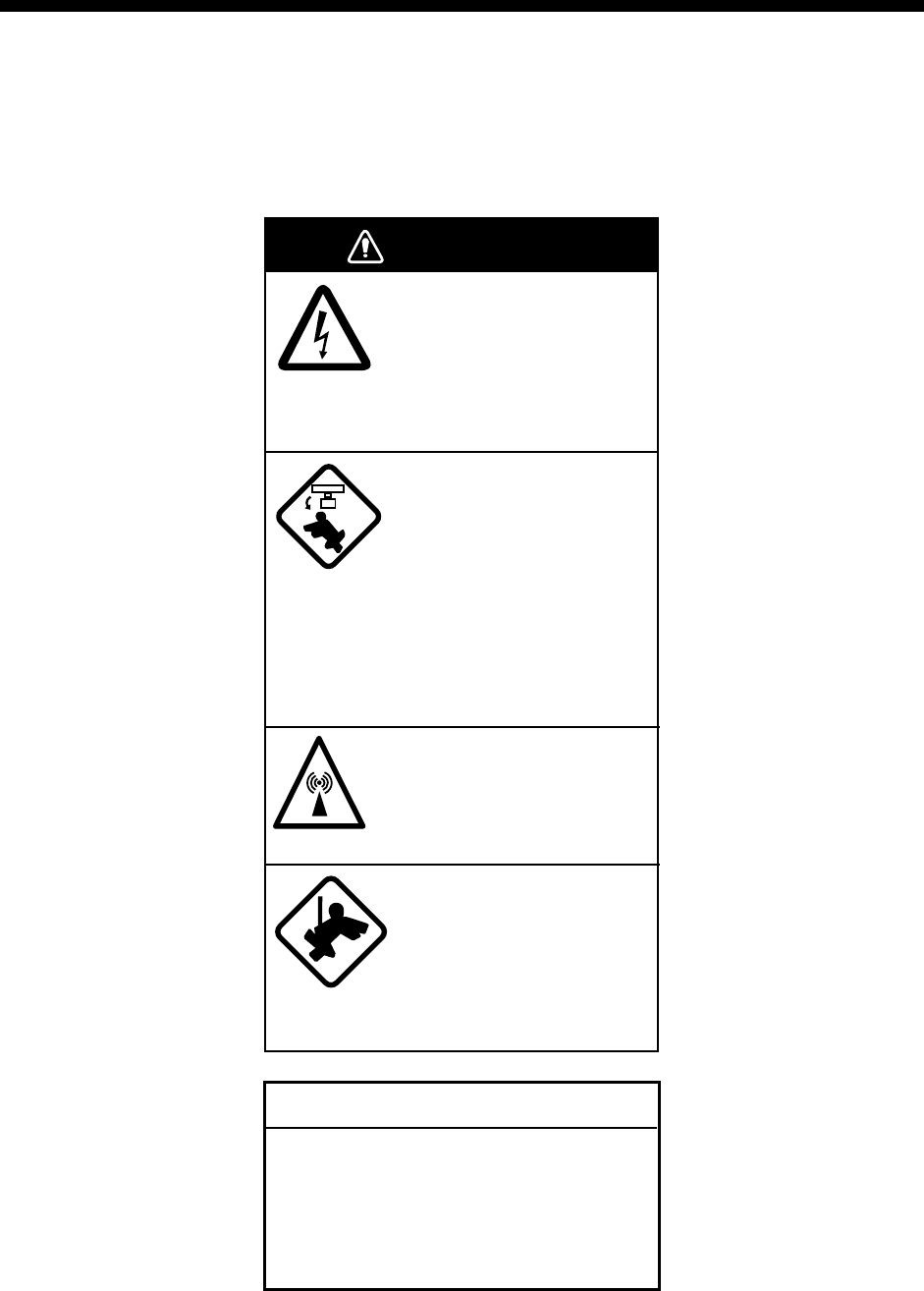
6-1
6. MAINTENANCE,
TROUBLESHOOTING
Periodic checks and maintenance are important for proper operation of any
electronic system. This chapter contains maintenance and troubleshooting
instructions to be followed to obtain optimum performance and the longest
possible life of the equipment. Before attempting any maintenance or
troubleshooting procedure please review the safety information below.
WARNING
Do not open the equipment.
Hazardous voltage which can
cause electrical shock exists
inside the equipment. Only
qualified personnel should
work inside the equipment.
Turn off the radar power
switch before servicing the
antenna unit. Post a warn-
ing sign near the switch
indicating it should not be
turned on while the antenna
unit is being serviced.
Prevent the potential risk of
being struck by the rotating
antenna.
A transmitting radar
antenna emits electromag-
netic waves, which can be
harmful, particularly the
eyes.
Wear a safety belt and hard
hat when working on the
antenna unit.
Serious injury or death can
result if someone falls from
the radar antenna mast.
NOTICE
Do not apply paint, anti-corrosive sealant
or contact spray to coating or plastic
parts of the equipment.
Those items contain organic solvents that
can damage coating and plastic parts,
especially plastic connectors.

6. MAINTENANCE, TROUBLESHOOTING
6-2
6.1 Periodic Maintenance Schedule
Regular maintenance is essential to good performance. A regular maintenance
program should be established and should at least include the items shown in
the table below.
Maintenance schedule
Interval Check point Check and measures Remarks
The LCD will in
time accumulate a
layer of dust which
tends to dim the
picture
Wipe the LCD carefully to
prevent scratching, using
tissue paper and an LCD
cleaner. To remove stubborn
dirt, use an LCD cleaner,
wiping slowly with tissue
paper so as to dissolve the
dirt. Change paper frequently
so the dirt will not scratch the
LCD.
Do not use chemical-based
cleaners to clean the LCD. They
can damage the LCD coating.
When
needed
Processor unit
cleanliness
Dust and dirt may be
removed with a soft cloth.
Do not use chemical-based
cleaners to clean the processor
unit. They can remove paint and
markings.
Exposed nuts and
bolts on antenna
unit
Check for corroded or
loosened nuts and bolts. If
necessary, clean and repaint
them thickly. Replace them if
heavily corroded.
Sealing compound may be used
instead of paint. Apply a small
amount of grease between nuts
and bolts for easy removal in
future.
Antenna radiator Check for dirt and cracks on
radiator surface. Thick dirt
should be wiped off with soft
cloth dampened with fresh
water. If a crack is found,
apply a slight amount of
sealing compound or
adhesive as a temporary
remedy, then call for repair.
Do not use chemical-based
cleaners for cleaning. They can
remove paint and markings. If
you need to remove ice from the
antenna unit, use a wooden
hammer or plastic head
hammer. Crack on the unit may
cause water ingress, causing
serious damages to internal
circuits.
3 to 6
months
Terminal strips and
plugs in antenna
unit
(TECHNICIANS
only)
Open antenna cover to check
terminal strip and plug
connections inside. Also
check the rubber gasket of
antenna covers for
deterioration.
When closing antenna covers in
position, be careful not to catch
loose wires between covers and
unit.
6 months to
one year
Terminal strips,
sockets, earth
terminal on
processor unit
(TECHNICIANS
only)
Check for loose connections.
Check contacts and plugs for
proper seating, etc.

6. MAINTENANCE, TROUBLESHOOTING
6-3
6.2 Life Expectancy of Major Parts
Parts Type Life
expectancy
Remarks
Antenna Motor D8G-516 (24 rpm, X-band)
D8G-571 (42 rpm, X-band)
GOB-8222 (18/22 rpm, X-band)
RM-6585 (22 rpm, X-band)
RM-7398 (21/26 rpm, S-band)
RM-7435 (21/26 rpm, S-band)
RM-9519 (45 rpm, S-band)
RM-9520 (45 rpm, S-band)
RM-9520 (45 rpm, S-band)
Gear motor
10,000 h
Carbon brush MG120-5X6X11 D8G (X-band) 2,000 h Check for wear when
replacing magnetron.
Replace if worn.
Magnetron MAF-1565N (X-band, 12 kW)
MG4010 (X-band, 12 kW)
MG5436 (X-band, 25 kW)
MG5223F (S-band, 30 kW)
4,000 h
4,000 h
4,000 h
7,000 h
Check no. of hours
used at Tx time. Reset
time after replacement.
Backlight Unit for
Display Unit
MU-201CR
201LHS2F 45,000 h (25°C)
30,000 h (50°C)
Replace when brilliance
is uneven or too low.
Cold Cathode
Fluorescent Lamp
for Display Unit
MU-231CR
FLCL-23 50,000 h (25°C)
35,000 h (50°C)
Replace when brilliance
is uneven or too low.
LCD assy.
(MU-170C)
856JAU1745V3 40,000 h
The life expectancy figures are typical values. Actual life depends on usage.
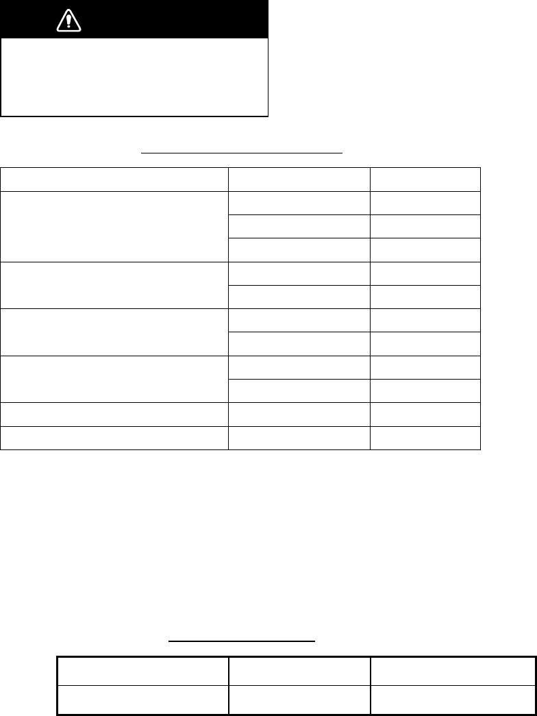
6. MAINTENANCE, TROUBLESHOOTING
6-4
6.3 Replacing the Fuse
The fuse at the rear of the processor unit and the display unit protects the
equipment from overcurrent and equipment fault. If you cannot turn on the power,
first check the fuse. Find the cause of the trouble before replacing the fuse.
WARNING
Use the proper fuse.
Use of a wrong fuse can result in damage
to the equipment or cause fire.
Ship’s mains and fuse to use
Unit Power Fuse to use
24 VDC 20A
100-115 VAC 10A
Processor Unit
220-230 VAC 5A
100-230 VAC 2A
Display Unit MU-201CR 24 VDC 5A
100-230 VAC 2A
Display Unit MU-231CR 24 VDC 6A
12 VDC 10A
Display Unit MU-170C 24 VDC 5A
Display Unit MU-231 100-230 VAC 1.5A
Display Unit MU-190 100-230 VAC 1 A
6.4 Replacement of Battery on GC Board
The battery installed on the GC (GyroCompass) Board inside the processor unit
preserves gyro data when the power is turned off. The life of the battery is about
five years. When the battery voltage is low, NG appears at the diagnostic test for
the GC Board. When this occurs, contact your dealer for replacement.
Battery on GC Board
Location of battery Battery type Code number
GC board CR 1/2 8.L 000-103-769
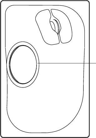
6. MAINTENANCE, TROUBLESHOOTING
6-5
6.5 Trackball Maintenance
If the cursor skips or moves abnormally, clean the trackball as below.
1. Turn the retaining ring counterclockwise 45° to unlock it.
Retaining Ring
2. Remove the retaining ring and ball.
3. Clean the ball with a soft, lint-free cloth, then blow carefully into the ball-cage
to dislodge dust and lint.
4. Look for a build-up of dirt on the metal rollers. If dirty, clean the rollers using a
cotton swab moistened lightly with isopropyl-rubbing alcohol.
5. Make sure that fluff from the swab is not left on the rollers.
6. Replace the ball and retaining ring. Be sure the retaining ring is not inserted
reversely.

6. MAINTENANCE, TROUBLESHOOTING
6-6
6.6 Easy Troubleshooting
This section provides troubleshooting procedures that the user may follow to
restore normal operation. If you cannot restore normal operation, do not attempt
to check inside any unit. Any repair work is best left to a qualified technician.
Easy troubleshooting procedures
Problem Cause Remedy
Key beep inaudible Key beep turned off
Adjust key beep level on the OPERATION menu,
referring to section 1.43.
Picture not updated or
picture freeze. 30
seconds after the
picture freezes, the
buzzer sounds, the
[ALARM ACK] key
blinks and alarm
signal is output.
Video freeze Turn the power off and on again to restore normal
operation.
Power is ON but
nothing appears on
monitor.
Brilliance is too low. Keyboard-type control unit: Turn BRILL control
clockwise to increase the brilliance.
Trackball-type control unit: Press any one of
F1-F4 for five seconds to increase the brilliance to
"50".
Marks, indications and
noise appear but no
echo
Tx high voltage
protection circuit has
activated.
Reset the power to restore normal operation.
Range changed but
radar picture does not
change
Defective range key
or video freeze up
Try to hit RANGE [+] and [-] keys (or RANGE box)
several times. (If unsuccessful, replacement of
keypad may be required in case of the
keyboard-type control unit.) If that does not work
try to turn the power off and on again to see if the
problem might be video freeze up.
Only 2 PI lines when 6
lines are wanted
Incorrect setting of
PI line interval
Incorrect setting of PI line interval. Adjust PI line
interval, referring to section 1.31.2. Also, the
setting for number of PI lines to display may be
inappropriate. Check the menu setting for number
of PI lines, referring to section 1.31.4.
Range rings are not
displayed
Range rings turned
off
Try turning on the range rings with 0 RINGS in the
MARK menu. If they do not appear, their brilliance
may be too low. Adjust their brilliance at page 1 of
the BRILL menu.
Tracked target not
tracked correctly
Poor definition of
targets in sea clutter
Adjust A/C SEA and A/C RAIN referring to section
1.17 and 1.18.
Tuning adjusted but
poor sensitivity
2nd trace echo
rejector on or dirt on
radiator face
• Turn off the 2nd trace echo rejector, referring to
section 1.38.
• Clean the radiator face.

6. MAINTENANCE, TROUBLESHOOTING
6-7
6.7 Advanced-level Troubleshooting
This section describes how to cure hardware and software troubles that should
be carried out by qualified service personnel.
Note 1: This radar equipment contains complex modules in which fault
diagnosis and repair down to component level are not practicable by
users.
Note 2: When replacement of the SPU board is necessary, the previous settings
can be transferred to new SPU board as follows:
- Use the CU-200 to save settings to a RAM card.
- After replacing the SPU board, load the entire contents of the RAM
card to the radar, referring to section 5.12 for the procedure.
Advanced troubleshooting
Problem Probable causes or check
points
Remedy
Power turned on but radar
does not operate at all
1) Blown fuse.
2) Mains voltage/polarity
3) Power supply board
1) Replace blown fuse.
2) Correct wiring and input voltage.
3) Replace power supply board.
Brilliance adjusted but no
picture
SPU board Replace SPU board.
Antenna not rotating 1) Antenna drive
mechanism
2) Defective antenna drive
motor relay (thermal
relay K2, 200/220/380,
440/100 VAC)
1) Replace antenna drive mechanism.
2) Press relay reset button.
Data and marks not
displayed in Transmit
status
SPU board Replace SPU board.
Adjust GAIN with A/C SEA
set at minimum. Marks and
indications appear but no
noise or echo
1) IF amplifier
2) Signal cable between
antenna and processor
unit
3) Video amplifier board
1) Replace IF amplifier.
2) Check continuity and isolation of
coaxial cable.
Note: Disconnect the plug and lugs
at both ends of coaxial cable before
checking it by ohmmeter.
3) Check video coax line for secure
connection. If connection is good,
replace SPU board.
(Continued on next page)

6. MAINTENANCE, TROUBLESHOOTING
6-8
Advanced troubleshooting (con’t)
Problem Probable causes or check
points
Remedy
Marks, indications and
noise appear but no echo
(Transmission leak
representing own ship
position is absent)
1) TX high voltage
protection circuit has
activated.
2) Magnetron
3) Modulator board
4) SPU board
1) Reset power to restore normal
operation.
2) Check magnetron current.
Replace magnetron.
3) Replace modulator board.
4) Replace SPU board.
Picture not updated or
picture freeze-up
1) Bearing signal generator
board (in antenna unit)
2) SPU board
3) Video freeze-up
1) Check the connection of signal
cables.
2) Replace SPU board.
3) Turn off and on the radar.
Incorrect orientation of
picture
1) SPU board
2) Gyro interface
1) The message HDG SIG MISSING
appears when the heading pulse is
not received during transmitting.
2) Replace the gyro interface.
Cannot operate radar from
on-screen boxes
SPU Board Replace SPU Board.
Radar is properly tuned but
poor sensitivity
1) Deteriorated magnetron
2) Detuned MIC
3) Dirt on radiator face
4) Water ingress to the
waveguide or other
feeder line
5) Second trace echo
rejection is ON
1) With the radar transmitting on 48 nm
range, check magnetron current.
If current is below normal, magnetron
may be defective. Replace it.
2) Check MIC detecting current. If it is
below normal value, MIC may have
become detuned. MIC must be
tuned.
3) Clean the radiator surface.
4) Remove water from the feeder line.
5) Disable the second-trace echo
rejector referring to section 1.38.
Range changed but radar
picture not changing
1) Defective range key
2) SPU board
3) Video freeze up
1) Try to hit RANGE [+] and [-] keys
several times. If unsuccessful,
replacement of keypad may be
required.
2) Replace SPU board.
3) Turn off and on radar.
(Continued on next page)

6. MAINTENANCE, TROUBLESHOOTING
6-9
Advanced troubleshooting (con’t)
Problem Probable causes or check
points
Remedy
Interference rejector is
inoperative (interference
rejection level not
displayed)
SPU board Replace SPU board.
Echo stretch is ineffective
(neither ES1, ES2 nor ES3
is displayed)
SPU board Replace SPU board.
Range rings are not
displayed
1) Adjust the brilliance of
range rings on the
BRILL menu to see if
intensity is increased
2) SPU board
1) Replace associated circuit board if
unsuccessful.
2) Replace SPU board.
Poor discrimination in
range
Sea clutter control not
functioning properly
Improper setting of A/C SEA. If A/C SEA
is seen only at very close range,
suspect inaccurate frequency of
reference oscillator.
True motion presentation
not working correctly
1) Poor contact of MODE
key (full keyboard)
2) Selection not accessed.
3) Speed entry incorrect
4) TM display inaccurate
1) Try to press MODE key a little
harder.
2) Press MODE key or operate
PRESENTATION MODE box until TM
appears.
3) Enter correct own ship speed
referring to section 1.13.
4) Make sure that speed and compass
inputs are accurate.
Target not tracked
correctly
Poor definition of targets in
sea clutter
Adjust A/C SEA and A/C RAIN controls
referring to section 1.17 and 1.18.
Buttons on trackball
module operated but no
response
Trackball module Replace trackball module.

6. MAINTENANCE, TROUBLESHOOTING
6-10
[CUSTOMIZE•TEST]
1 BACK
2 [DATA BOX]
3 [F1]
4 [F2]
5 [F3]
6 [F4]
7 [OPERATION]
8 [TEST]
[TEST]
1 BACK
2 [SELF TEST]
3 [TT TEST]
6.8 Diagnostics
A diagnostic test program is provided to test major circuit boards in the control
unit, processor unit and card I/F unit. Note that the normal radar picture is lost
during this test.
Proceed as follows to execute the diagnostic test:
1. Left-click the MENU box to open the menu.
2. Select 9 [CUSTOMIZE•TEST].
CUSTOMIZE•TEST menu
3. Select 8 [TEST].
TEST menu
4. Select 2 [SELF TEST] .
SELF TEST menu
5. Select 2 START to start the test.
In a few moments the results of the test are displayed and the buzzer
sounds continuously. The ROMs and RAMs of the SPU, RFC, KEYBOARD
(Control Unit), REMOTE (Trackball-only Control Unit) and CARD I/F UNIT
are checked for proper operation. OK appears for normal operation. If NG
(No Good) appears, corresponding components may be defective. Consult
your dealer. In the middle of the display the rpm of the antenna unit and
various voltages are displayed.
[SELF TEST]
1 BACK
2 START
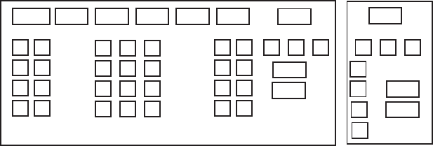
6. MAINTENANCE, TROUBLESHOOTING
6
-
11
<SELF TEST>
PROGRAM No. ROM RAM DIP SW
SPU 0359204-03.** OK OK 0000
RFC 0359202-01.** OK OK
KEY 0359203-01.** OK OK
REMOTE1 0359203-01.** OK OK
REMOTE2
CARD 0359209-01.** OK OK 0000
PROCESSOR UNIT MONITOR
-12V -11.6
3.3V 3.3
5V 4.9
12V 11.6
SCANNER MOTOR 20.7
RF UNIT MONITOR
TEMPERATURE 27.3
TUNE IND 1.4
HV 527.9
R. MONITOR 1.6
MAG. CURRENT 1.5
HEATER 1.8
12V 11.9
-12V -11.8
5V 4.8
32V 31.8
TUNE OUT 19.2
TRIGGER FREQ 2273
ANT SPEED 21.6
*.**: Program Version No.
#: Installed card units are shown.
00 0 0 0 0
0
0
0
0
0
0
#
Self test results, keyboard test
6. The small squares and circles displayed at the bottom of screen are for
testing the control and keys on the control unit. As you operate controls and
keys, corresponding squares are highlighted, indicating that your control/key
operations are properly recognized. Numerals indicate the position of the
controls under check.
6. MAINTENANCE, TROUBLESHOOTING
6-12
7. Press the [F1] key to change the display. The buzzer stops and the screen
shows the sentences being input from external equipment (GPS1,
GPS2SPEED, HEADING and NAV DATA). Below is an example. The
sentences shown depend on your system settings.
<GPS1>
GGA
GLL
RMC
RMB
VTG
ZDA
DTM
BWR
BWC
<GPS2>
GGA
GLL
RMC
RMB
VTG
ZDA
DTM
BWR
BWC
<SPEED>
VBW
VHW
VDR
<HEADING>
HDT
<NAV DATA>
WPL
RTE
MWV
VWT
VWR
DPT
DBT
DBS
MTW
VDM
Sentence input display
6. MAINTENANCE, TROUBLESHOOTING
6-13
8. Press the [F1] key again to show the data sentences input from AIS and INS.
<AIS>
VDO
VDM
<INS>
ZDA
GGA
GLL
OSD
DPT
MWV
DTM
FUGLL
PAESP
PAESC
PAESF
PLSPL
PLSPS
PAESW
PAESN
8. To terminate the test, press the [F1] key.
6. MAINTENANCE, TROUBLESHOOTING
6-14
This page intentionally left blank.
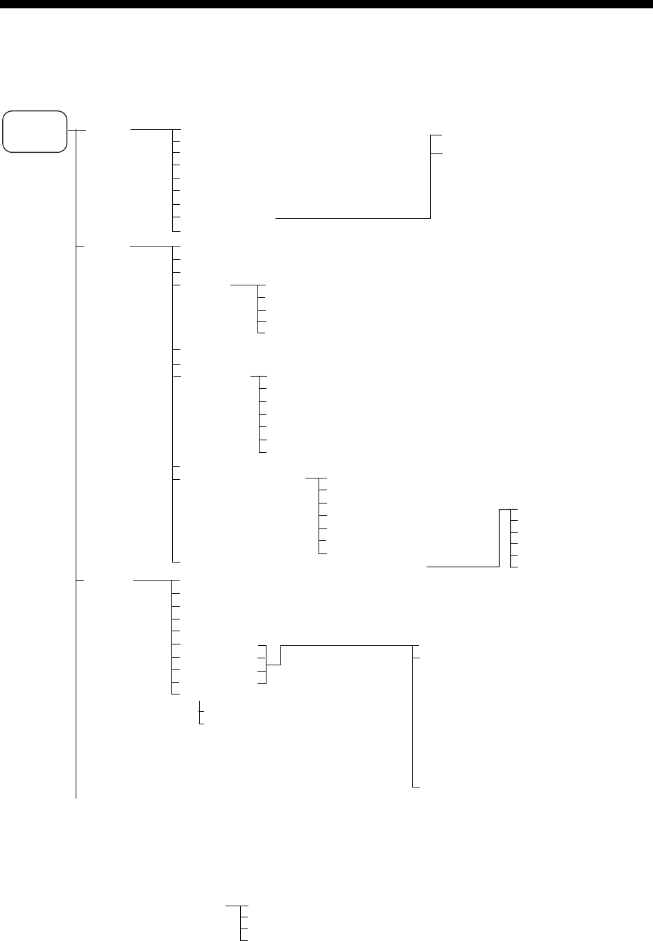
AP-1
APPENDIX
1. Menu Tree
Main menu (accessed by MENU key or MENU box)
1 ECHO
2 MARK
3 ALARM
(Continued on next page)
1 BACK
2 2ND ECHO REJ (OFF, ON)
3 TUNE INITIALIZE
4 PM (OFF, ON)
5 SART (OFF, ON)
6 WIPER (OFF, 1, 2)
7 ECHO AREA (CIRCLE, WIDE, ALL)*
1
8 [PICTURE SELECT]
9 STC RANGE (-10 to +10, 00)
MENU key
or
MENU box
1 BACK
2 (TARGET ALARM, WATCH ALARM,
TT NEW TARGET, TT LOST TARGET,
TT CPA LIMIT, TT AUTO ACQ TGT FULL,
TT MAN ACQ TGT FULL, TT SYSTEM ERROR,
AIS NEW TARGET, AIS LOST TARGET,
AIS CPA LIMIT, AIS TGT FULL, AZIMUTH, HEAD
LINE, TRIGGER, VIDEO, GYRO, LOG,
EPFS, XTE, ARRIVAL WPT, DEPTH,
ALARM ACK OUT, OPERATOR FITNESS,
ANCHOR WATCH, NO CPA/TCPA FOR AIS)
9 ALARM OUT POLARITY (NORMAL, INVERT)
1 BACK
2 EBL1 (REL, TRUE)
3 EBL2 (REL, TRUE)
4 VRM1 (NM, SM, km, kyd)
5 VRM2 (NM, SM, km, kyd)
6 CURSOR BEARING (REL, TRUE)
7 CURSOR RANGE (NM, SM, km, kyd)
8 [CURSOR SHAPE]*
1
1 BACK
2 OWN SHIP MARK (OFF, MIN, SCALED)
3 STERN MARK (OFF, ON)
4 [PI LINE]
5 ANCHOR WATCH (OFF, ON, 0.00NM)
6 DROP MARK (OFF, ON)
7 [INS MARK]*
5
8 EBL OFFSET BASE (STAB GND , STAB HDG, STAB NORTH)
9 [EBL, VRM, CURSOR SET]*
6
0 RING (OFF, ON)
1 BACK
2 TARGET ALARM MODE (IN, OUT)
3 TARGET ALARM LEVEL (1, 2, 3, 4)
4 WATCH ALARM (OFF, 6M, 10M, 12M, 15M, 20M)
5 ALARM SOUND LEVEL (OFF, LOW, MID, HIGH)
6 [ALARM OUT1]
7 [ALARM OUT2]
8 [ALARM OUT3]
9 [ALARM OUT4]
0 [PRIMARY ALARM]
*
1
Not available on IMO or A type.
*
2
W type shows PI LINE1. Same choices as "PI LINE".
*
3
W type shows PI LINE2. Same choices as "PI LINE".
*
4
Appears when 3 PI LINE is set for other than "1".
Not shown on IMO or A type.
*
5
When INS MARK is OFF, BARGE MARK menu appears.
*
6
IMO and A types show 9 EBL CURSOR BEARING (REL, TRUE).
1 BACK
2 USER CHART (OFF, ON)
3 CURVED EBL (OFF, ON)
4 CHART SYMBOL (OFF, ON)
5 NOTE BOOK (OFF, ON, DISPLAY)
6 ROUTE (OFF, CENT, ALL)
7 PREDICTOR (OFF, ON)
7 [BARGE MARK] 1 BACK
2 BARGE MARK (OFF, ON)
3 BARGE SIZE (LENGTH and WIDTH)
4 ARRANGEMENT
1BACK
2 (PICTURE 1 (OFF, ON),
PICTURE 2 (OFF, ON),
PICTURE 3 (OFF, ON),
PICTURE 4 (OFF, ON),
NEAR (OFF, ON),
FAR (OFF, ON),
NEAR BUOY (OFF, ON),
FAR BUOY (OFF, ON),
ROUGH SEA (OFF, ON),
SHIP (OFF, ON),
HARBOR (OFF, ON),
COAST (OFF, ON))
1 BACK
2 PI LINE BEARING (REL, TRUE)*
2
3 PI LINE (1, 2, 3, 6*
3
)
4 PI LINE MODE (PARALLEL , PERPENDIC.)*
4
5 RESET PI LINE (NO, YES)
1 BACK
2 (TARGET ALARM, WATCH ALARM, TT NEW
TARGET, TT LOST TARGET, TT AUTO ACQ TGT
FULL, TT MAN ACQ TGT FULL, AIS NEW
TARGET, AIS LOST TARGET, AIS TGT FULL
XTE, ARRIVAL WPT, DEPTH ANCHOR WATCH,
NO CPA/TCPA FOR AIS)
1 BACK
2 CURSOR (OFF, ON)
3 FRONT HALF LENGTH
4 REAR HALF LENGTH
5 NET WIDTH
6 ROTATE STEP
(360
°, 32 POINTS)

APPENDIX
AP-2
4 TT
AIS
5 PLOTTER
1 BACK
2 AZ STAB (STAB HDG, STAB NORTH)
3 AZ POLYGON (OFF, STAB GND, STAB HDG, STAB NORTH)
4 [TRIAL MANEUVER]
5 [TT
AIS SYMBOL]
6 [CPA AUTO ACTIVATE]
7 [AIS DISP FILTER]
8 [AIS LOST FILTER]
9 [TT LOST FILTER]
0 [ASSOCIATION]
1 BACK
2 TRIAL (OFF, STATIC, DYNAMIC)
3 TRIAL SPEED RATE ( 0-99 kn, 0.00-99.99 kn/s, two sets)
4 TRIAL TURN RATE ( 0-99 kn, 0.00-99.99 kn/s, two sets)
5 TRIAL TGT DATA ( ACTUAL , TRIAL)
1 BACK
2 TT
AIS SYMBOL COLOR (RED, GRN, BLU, CYA, MAG, WHT)
3 AIS ROT TAG LIMIT (000.0°-720.0°/min)
4 TT PAST POSN POINTS (5, 10)
5 AIS PAST POSN POINTS (5,10)
6 AIS SCALED SYMBOL (OFF, ON)
1 BACK
2 MAX RANGE (OFF, ON, 0-99 NM)
3 MIN SHIP SPEED (OFF, ON, 0.0-9.9 kn)
4 EXCEPT CLASS B (OFF, ON)
5 MIN SHIP LENGTH (OFF, ON, 0-999 m)
1 BACK
2 CHART COLOR (GRN, YEL, CYA, ORANGE, GRAY)*
3 OWN TRACK INTERVAL (OFF, DRAW, 10S, 30S, 1M, 2M, 3M, 6M, 15M)
4 OWN TRACK COLOR (RED, GRN, BLU, YEL, CYA, MAG, WHT)
5 TGT TRACK INTERVAL (OFF, DRAW, 10S, 30S, 1M, 2M, 3M, 6M, 15M)*
6 TGT TRACK COLOR (RED, GRN, BLU, YEL, CYA, MAG, WHT)*
7 CURSOR L/L ALIGN (OFF, ON)
8 [DATA ERASE] 1 BACK
2 OWN TRACK (RED, GRN, BLU, YEL, CYA, MAG,
WHT, 30%, 50%, 80%, ALL)
3 TARGET TRACK (RED, GRN, BLU, YEL, CYA, MAG,
WHT, 30%, 50%, 80%, ALL)**
4 MARK ALL ERASE (NO, YES)
5 WPT ALL ERASE (NO, YES)
6 NAV LINE ALL ERASE (NO, YES)
7 OWN TRACK DELETE (2POINTS, AREA)**
8 TARGET TRACK DELETE (2POINTS, AREA)**
(Continued on next page)
(Continued from previous page)
* Not available on IMO type radar
** Not available on IMO or A type radar
1 BACK
2 MAX RANGE (OFF, ON, 0-99 NM)
3 MIN SHIP SPEED (OFF, ON, 0.0-9.9 kn)
4 EXCEPT CLASS B (OFF, ON)
5 MIN SHIP LENGTH (OFF, ON, 0-999 m)
1 BACK
2 MAX RANGE (OFF, ON, 0-99 NM)
3 MIN SHIP SPEED (OFF, ON, 0.0-9.9 kn)
4 EXCEPT CLASS B (OFF, ON)
5 MIN SHIP LENGTH (OFF, ON, 0-999 m)
1 BACK
2 MAX RANGE (OFF, ON)
3 MIN SHIP SPEED (OFF, ON)
1 BACK
2 ASSOCIATION TARGET (OFF, AIS, TT)
3 GAP (0.000-0.999(nm))
4 RANGE (0.000-0.999(nm))
5 BEARING (00.0-99.9°)
6 SPEED (0.0-9.9(kn))
7 COURSE (00.0-99.9°)
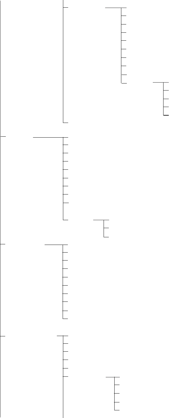
APPENDIX
AP-3
9 [DISPLAY]
0 AUTO TARGET TRACK (OFF, ON)*
1 BACK
2 GRID (OFF, L/L )
3 OWN TRACK (OFF, ON)
4 TARGET TRACK (OFF, ON)*
5 MARK (OFF, ON)
6 LAND DENSITY (OFF, ON)*
7 PLACE NAME (OFF, ON)*
8 COAST LINE (OFF, ON)
9 CONTOUR LINE (OFF, ON, DEPTH)
0 NEXT 1 BACK
2 NAV LINE(MAP) (OFF, ON)
3 DANGER HIGHLIGHT (OFF, ON)
4 PROHIBITED AREA (OFF, ON)
5 BUOY (OFF, ON)
(Continued on next page)
(Continued from previous page)
6 CARD
7 NAV DATA
8 NAV LINE
WPT
1 BACK
2 DRIVE SELECT
3 READ CARD
4 WR MARK
5 WR NAV LINE
WPT
6 WR OWN TRACK
7 WR TARGET TRACK*
8 WR SETTING DATA
9 WR INSTALL DATA
0 NEXT 1 BACK
2 FILE DELETE
3 CARD INITIALIZE
1 BACK
2 DEPTH (OFF, m, ft)
3 DEPTH GRAPH SCALE (10, 20, 50, 100, 200, 500)
4 DEPTH MARK (000 - 500)
5 CURRENT (OFF, ON)
6 WIND (OFF, m/s, kn, RELATIVE, TRUE THEORETICAL, TRUE NORTH)
7 TEMP (OFF, ON)
8 DATE-TIME (OFF, UTC, LOCAL)
9 LOCAL TIME ADJ (00:00 - +13:30)
0 WPT DATA (OFF, REL, TRUE)
1 BACK
2 NAV LINE DATA SOURCE (OFF, EXT DATA, INTERNAL DATA, WPT*)
3 NAV LINE SELECT (Enter nav line no., FORWARD, REVERSE)
4 SKIP NEXT WPT
5 NAV LINE WIDTH (0.00 - 9.99 (NM))
6 [WPT SET] 1 BACK
2 WPT NO. SELECT
3 WPT NAME
4 WPT L/L
5 CLEAR DATA (NO, YES)
* Not available on IMO type

APPENDIX
AP-4
7 [WPT LIST]
8 [NAV LINE SET]
9 [NAV LINE LIST]
0 NEXT
(Continued on next page)
(Continued from previous page)
9 CUSTOMIZE
TEST
1 BACK
2 [DATA BOX]
3 [F1]
4 [F2]
5 [F3]
6 [F4]
1 BACK
2 NAV LINE NO. SELECT
3 NAV LINE NAME
4 NAV LINE ENTER
5 CLEAR DATA
1 BACK
2 ARRIVAL WPT ALARM (OFF, ON(0.00-9.99 nm))
3 TURNING LINE (OFF, ON, REVISED)
4 DISP WPT NO. (OFF, ON)
5 DISP WPT NAME (OFF, ON)
1 BACK
3 NAV DATA (OFF, ON)
4 ZOOM (OFF, 2TIMES, 3TIMES)
5 ZOOM DISPLAY
(STAB GND, STAB HDG, STAB NORTH, TT TRACK)
6 TARGET DATA (1BOX, 2BOX, 3BOX, LARGE)
1 BACK
2 [ECHO]
3 [STD KEY]
4 [TT
AIS]
5 [OPERATION]
1 BACK
2 (PICTURE, IR, ES, EAV, NOISE
REJ, ANT SELECT, PULSE LENGTH,
A/C SEA SELECT, AUTO RAIN
SELECT, TUNE SELECT, ANT
HEIGHT, SEA CONDITION, 2ND
ECHO REJ, PM, SART, WIPER)
1 BACK
2 (ALARM ACK, STBY TX, HL
OFF, EBL OFFSET, MODE, OFF
CENTER, CU TM RESET, PI
LINE, VECTOR TIME, VECTOR
MODE, TARGET LIST, TRAIL,
BRILL, MARK, MENU, RANGE
UP, RANGE DOWN, ACQ,
TARGET DATA, TARGET CANCEL)
1 BACK
2 (DISP TT, DISP AIS, TARGET
DATA & ACQ, PAST POSN
INTERVAL, REF MARK, CPA LIMIT,
CPA, TCPA, AZ1, AZ2, TARGET LIST
SORT, TRIAL MANEUVER, ASSOCIATION,
AIS MESSAGE, TRIAL MODE CHANGE,
AIS SCALED SYMBOL)
1 BACK
2 (ECHO COLOR, PALETTE,
RING, ALARM1, ALARM2, WATCH
ALARM RESET, ZOOM, MARK
DELETE, OWN TRACK DELETE,
TGT TRACK DELETE*, CHART ALIGN,
DISPLAY SELECT, MOB, USER DEFAULT
TLL, ANCHOR WATCH, COLOR SHIFT,
ICON DISP, OWN TRK ALL ERASE,
TGT TRK ALL ERASE, MARK ALL ERASE,
DROP MARK)
Default settings:
F1: IR
F2: ES
F3: AUTO RAIN SELECT
F4: HL OFF
* B, C and W types

APPENDIX
AP-5
7 [OPERATION]
8 [TEST]
(Continued from previous page)
1 BACK
2 WHEEL DRIVE (NORMAL, REVERSE)
3 KEY BEEP (OFF, LO, MID, HI)
4 REMOTE KEY (F*-KEY, DISPLAY SELECT)
5 POPUP GUIDANCE (OFF, ON)
*1
6 OWN SHIP VECTOR (OFF, HDG, COURSE)
7 STERN-UP (OFF, ON)
8 SHUTTLE FERRY (OFF, MODE1, MODE2)
0 NEXT
1 BACK
2 [SELF TEST]
3 [TT TEST]
6 [PICTURE] 1 BACK
2 (PICTURE1, PICTURE 2, PICTURE 3, PICTURE 4,
NEAR, FAR, NEAR BUOY, FAR BUOY, ROUGH SEA, SHIP,
HARBOR, COAST)
*1
Not available on IMO or A type
1 BACK
2 USER DEFAULT BACKUP
(F-KEY, HOLD, STORE)
3 VRM TTG
(OFF/ 1/ 2/ 1+2)

APPENDIX
AP-6
Pop-up menus of on-screen boxes
[TT TARGET MENU]
1 TT SELECT
MANUAL 100
/
AUTO 25/
AUTO 50/
AUTO 75/
AUTO 100
ALL CANCEL
NO/YES
2
3
REF TARGET VECTOR
OFF
/ON
TT TARGET menu
[AIS TARGET MENU]
1 SLEEP ALL TRGTS
2 ACTIVATE ALL TRGTS
3 AUTO DISP MESSAGE
/ON
4
[RECEIVED MESSAGES]
5 [TRANSMIT MESSAGE]
6 [VOYAGE DATA]
7 [STATIC DATA]
8 [AIS ALM MESSAGES]
AIS TARGET menu
OS POSN menu
[VOYAGE DATA]
1 BACK
2 NAVIGATION STATUS
00
3 ETA
00/000/0000 00:00
4 DESTINATION
5 DRAUGHT
00.0m
6 CREW
0002
[TRANSMIT MESSAGE]
1 BACK
2 ADDRESS TYPE
ADDRESSED/BROADCAST
3 MESSAGE TYPE
SAFETY/BINARY
4 MMSI NO. 000000000
5 CHANNEL
A/B/A or B/A and B
6 OPEN FILE 1
7 SAVE FILE 1
8 EDIT
9 TRANSMIT MESSAGE
TRANSMIT MESSAGE menu VOYAGE DATA menu STATIC DATA menu
[TRAIL MENU]
1 TRAIL MODE
REL
/TRUE
2 TRAIL GRAD
SINGLE
/MULTI
4 TRAIL LEVEL
1
/2/3/4
5 TRAIL RESTART
OFF/
ON
6 TRAIL COPY
OFF/
ON
7
[TARGET LIST MENU]
CPA
/TCPA/BCR/BCT/
RANGE/SPEED
TGT LIST menu
1 SORT BY
OS TRAIL
OFF
/1/2
TRAIL menu
3 NARROW TRAIL
*3
,
*4
OFF
/1/2
*1
Shown when 12H, 24H or 48H is
chosen at 8 TRAIL LENGTH.
*2
B and W types. 48H not
available on W type.
*3
Not available on IMO type
*4
Not available on A type
8 TRAIL LENGTH*
2
NORMAL/12/24H/48H
CURSOR menu
[OS POSN MENU]
1 NAV AID
GPS
1/GPS2/
DEAD RECKONING/
2 MANUAL L/L
00
°
00.000 N
000
°
00.000 W
3 SIO DATA LAN OUTPUT
OFF
/ON
LAN
NO/YES
NO/YES
9 TRAIL HIDE*
1
,*
3
,*
4
/
START: 00:00
END: 00:00
1BACK
TYPE OF SHIP
000
ALL SHIPS OF
THIS TYPE
CALL SIGN
NAME
EXT GPS ANT POSN
A: 000m B: 000m
C: 00m D: 00m
[STATIC DATA]
OFF
0 [TRAIL COLOR]*
3
,*
4
, *
5
[CURSOR MENU]
2
TARGET DATA & ACQ/
TARGET CANCEL/
TT TGT DATA & ACQ/
TARGET TRACK ON*
3
/
TARGET TRACK OFF*
3
/
REF MARK/
EBL OFFSET/
OFFCENTER/
ZOOM/
MARK DELETE/
OWN TRACK DELETE/
TGT TRACK DELETE*
3
/
CHART ALIGN
TRAIL ERASER*
3
,*
4
/
8
9 CURSOR*
3
,*
4
/
SMALL/LARGE
* Not available on IMO type
[HDG MENU]
1 HDG SOURCE
AD-10
/SERIAL
2 GC-10 SETTING
000.0
°
HDG menu
[SPD MENU]
1 SHIP SPEED
LOG(BT)/LOG(WT)/
GPS
/MANUAL/REF
2 MANUAL SPEED
0.0
kn
3 SET DRIFT
OFF/
ON
SPEED menu
*5
Not available on W type
[TRAIL COLOR]
1 BACK
2 COLOR SHIFT
NO/YES
3 TRAIL COLOR
1: FUCHSIA
2: MAROON
3: RED
4: PURPLE
5: YELLOW
6: LIME
7: GREEN
8: OLIVE
9: TEAL
10: CYAN
11: BLUE
12: NAVY
TRAIL COLOR menu

APPENDIX
AP-7
[MARK MENU]
1 ORIGIN MARK STAB
GND/SEA
2 MARK KIND
ORIGIN MARK(No. )/
ORIGIN MARK(SYM)/
MAP MARK /
WP 1~50/
WP 51~ 100/
WP 101~150/
WP 151~ 198/
OWN SHIP SHAPE
BRILL menu, page 1
[BRILL1 MENU (2/2)]
1 BACK
2 BEARING CURSOR
3 EBL
4 VRM
5 PI LINE
6 TT SYMBOL
7 AIS SYMBOL
8 L/L GRID
9 MARK
0 CHART*
[BRILL1 MENU (1/2)]
1 ECHO COLOR
YEL/GRN/
WHT/COLOR*
2 PALETTE
DAY-GRY/DAY-BLU/
DUSK-GRY/DUSK BLU/
NIGHT-GRY/NIGHT-BLU
3 PANEL DIMMER
4 CHARACTER
5 CURSOR
6 ECHO
7 TRAIL
8 HL
9 RING
0 NEXT
BRILL menu, page 2
MARK menu
[PICTURE MENU]
1 INT REJECT
OFF/1/2/3
2 ECHO STRETCH
OFF/1/2/3
3 ECHO AVERAGE
OFF/1/2/3
4 NOISE REJ
OFF/ON
5 AUTO STC
OFF/ON
6 AUTO RAIN
7
VIDEO CONTRAST
1/2/3/4 A/B/C
8
[PULSE]
9
[CONDITION]
PICTURE menu
OFF/1/2/3/4
PULSE menu
ANTENNA SELECT menu
[ANT SELECT]
ANT NO 1: X-BAND
12 MAIN TOP
ANT NO 2: X-BAND
12 MAIN TOP
ANT NO 3:
ANT NO 4:
OWN RADAR NO: 2
1 DISP ANT1
MASTER
2 DISP ANT2
MASTER
8 STORE INTER-SW
OFF/ON
9 SUB MONITOR*
OFF/ON
0 DEFAULT
NO/SAVE/FACTORY/
DEFAULT
8 MARK POSN
CURSOR/OS/L/L
00°000.00 N
000°000.00 E
9 MAP DISPLAY
OFF/ON
0 MAP MARK COLOR*
RED/GRN/BLU/YEL/
CYA/MAG/WHT
CONDITION menu
[CONDITION MENU]
1 BACK
2 SEA CONDITION
1/2/3/4/5
3 ANT HEIGHT
5/7.5/10/15/20/
25/30/25/30/35/40/45/
more 50 m
4 LOW LEVEL ECHO
0
* Not available on IMO or A type
[PULSE MENU]
1 BACK
2 0.5NM
S1/S2
3 0.75NM
S1/S2/M1
4 1.5NM
S1/S2/M1
5 3NM
S2/M1/M2/M3
6 6NM
M1/M2/M3/L
7 12-24NM
M2/M3/L
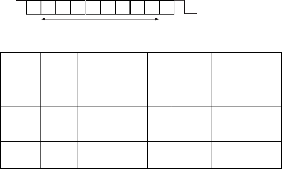
APPENDIX
AP-8
2. Digital Interface
Input sentences (RP Board, J4)
ABK, ACK, BWC*, BWR*, DBS, DBT, DPT, DTM, GGA, GLL, GNS, HDT, MTW, MWV, RMB,
RMC, RTE, THS, VBW, VDR, VHW, VTG, VWR, VWT, WPL, ZDA, !AIVDM, !AIVDO,
$AIALR
Output sentences
ABM, ALR, BBM, OSD, RSD, TLB, TLL*, TTD, TTM, VSD
*: Not available on IMO radar
Data reception
Data is received in serial asynchronous form in accordance with the standard referenced in
IEC 61162-2.
The following parameters are used:
Baud rate: 38,400 bps: HDT, !AIVDM, !AIVDO and $AIALR. All other sentences: 4800 bps
Data bits: 8 (D7 = 0), Parity: none, Stop bits: 1
D0 D1 D2 D3 D4 D5 D6 D7
Start
bit
Stop
bit
Data bits
Validity and integrity of input data (mode indicator)
Data
indication
HDG Latitude and Longitude SPD COG/SOG WP
GREEN color
(normal data)
THS-A
HDT
GNS-A,D*
GGA-1 2,3,4,5*
GLL-A,D and (status: A)*
RMC- A,D and (status: A)*
VBW-A
VHW
VTG-A,D
BWC-A,D
BWR-A,D
RMB-A,D and status A
RED color
(invalid data)
GNS-E,M,S,N
GGA-0,6,7,8
GLL-E,M,S,N or (status:V)
RMC-E,M,S,N or (status:V)
VBW-V
VTG-E,M,S,N
***.*
THS-E,M,S,N
BWC-E,M,S,N
BWR-E,M,S,N
RMB-E,M,S,N or (status:V)
* Low or doubtful integrity can occur when the GBS sentence gives RAIM error rate of 10 m
or higher and "Age of differential GPS data" in GGA and GNS sentences is 10 seconds or
higher. In this case the ship's latitude and longitude indications are shown in yellow.

APPENDIX
AP-9
Data sentences
Data used is shown in bold italics.
Input sentences
ABK - UAIS Addressed and binary broadcast acknowledgement
$--ABK,xxxxxxxxx,x,x.x,x,x*hh<CR><LF>
| | | | | |
| | | | | +--- 6
| | | | +----- 5
| | | +------- 4
| | +---------- 3
| +------------- 2
+------------------- 1
1. MMSI of the addressed AIS unit
2. AIS channel of reception
3. Message type
4. Message sequence number
5. Type of acknowledgement
6. Checksum
ACK – Acknowledge alarm
$--ACK,x.x,x.*hh<CR><LF>
| +------------ 2
+------------------- 1
1. Local alarm number (identifier)
2. Checksum
BWC - Bearing and distance to waypoint (Not available on IMO radar)
$--BWC, hhmmss.ss, llll.ll, a yyyyy.yy, a, x.x, T, x.x, M, x.x, N, c--c, a*hh<CR><LF>
Checksum
Mode indicator
(see note 1)
Waypoint ID
Distance, nautical miles
Bearing, degrees true
Waypoint longitude, E/W
Bearing, degrees magnetic
Waypoint latitude, N/S
UTC of observation
NOTE 1: Positioning system Mode indicator:
A = Autonomous
D = Differential
E = Estimated (dead reckoning)
M = Manual input
S = Simulator
N = Data not valid
The Mode indicator field shall not be a null field.
APPENDIX
AP-10
BWR - Bearing and distance to waypoint - rhumb line (Not available on IMO radar)
$--BWR,hhmmss.ss,llll.lll,a,yyyyy.yyy,a,x.x,T,x.x,M,x.x,N,c--c,a*hh<CR><LF>
| | | | | | | | | | | | | |
| | | | | | | | | | | | | +---- 9
| | | | | | | | | | | | +------ 8
| | | | | | | | | | | +--------- 7
| | | | | | | | | +--+------------- 6
| | | | | | | +--+------------------- 5
| | | | | +--+------------------------- 4
| | | +-----+------------------------------- 3
| +-----+------------------------------------------- 2
+---------------------------------------------------------- 1
1. UTC of observation
2. Waypoint latitude, N/S
3. Waypoint longitude, E/W
4. Bearing, degrees true
5. Bearing, degrees magnetic
6. Distance, nautical miles
7. Waypoint ID
8. Mode indicator (see note)
9. Checksum
NOTE Positioning system Mode indicator:
A = Autonomous
D = Differential
E = Estimated (dead reckoning)
M = Manual input
S = Simulator
N = Data not valid
The Mode indicator field shall not be a null field.
APPENDIX
AP-11
DTM - Datum reference
$--DTM,ccc,a,x.x,a,x.x,a,x.x,ccc*hh<CR><LF>
| | | | | | | | |
| | | | | | | | +--- 7
| | | | | | | +------ 6
| | | | | | +---------- 5
| | | | +--+------------- 4
| | +---+------------------- 3
| +------------------------- 2
+---------------------------- 1
1. Local datum W84 - WGS84
W72 - WGS72
S85 - SGS85
P90 - PE90
999 - User defined
IHO datum code
2. Local datum subdivision code
3. Lat offset, min, N/S
4. Lon offset, min, E/W
5. Altitude offset, m
6. Reference datum W84 - WGS84
W72 - WGS72
S85 - SGS85
P90 - PE90
7. Checksum
DBS - Depth below surface
$--DBS,x.x,f,x.x,M,x.x,F*hh<CR><LF>
| | | | | | |
| | | | | | +--------- 4
| | | | +--+----------- 3
| | +--+----------------- 2
+--+---------------------- 1
1. Water depth, feet
2. Water depth, m
3. Water depth, fathoms
4. Checksum
DBT - Depth below transducer
$--DBT,x.x,f,x.x,M,x.x,F*hh<CR><LF>
| | | | | | |
| | | | | | +--------- 4
| | | | +--+----------- 3
| | +--+----------------- 2
+--+---------------------- 1
1. Water depth, feet
2. Water depth, m
3. Water depth, fathoms
4. Checksum
APPENDIX
AP-12
DPT - Depth
$--DPT,x.x,x.x,x.x*hh<CR><LF>
| | | |
| | | +----- 4
| | +--------- 3
| +------------ 2
+---------------- 1
1. Water depth relative to transducer, in meters
2. Offset from transducer, in meters (see notes 1 and 2)
3. Maximum range scale in use
4. Checksum
NOTE1 "positive"=distance from transducer to water-line.
"-"=distance from transducer to keel.
NOTE2 For IEC applications the offset should always be applied
so as to provide depth relative to the keel.
GGA - Global positioning system fix data
$--GGA,hhmmss.ss,llll.lll,a,yyyyy.yyy,a,x,xx,x.x,x.x,M,x.x,M,x.x,xxxx*hh<CR><LF>
| | | | | | | | | | | | | | |
| | | | | | | | | | | | | | +-- 11
| | | | | | | | | | | | | +---- 10
| | | | | | | | | | | | +--------- 9
| | | | | | | | | | +---+------------ 8
| | | | | | | | +---+------------------ 7
| | | | | | | +------------------------- 6
| | | | | | +---------------------------- 5
| | | | | +------------------------------- 4
| | | +----+--------------------------------- 3
| +---+--------------------------------------------- 2
+------------------------------------------------------------- 1
1. UTC of position
2. Latitude, N/S
3. Longitude, E/W
4. GPS quality indicator (see note)
5. Number of satellite in use,00-12, may be different from the number in view
6. Horizontal dilution of precision
7. Antenna altitude above/below mean sea level, m
8. Geoidal separation, m
9. Age of differential GPS data
10. Differential reference station ID, 0000-1023
11. Checksum
NOTE
0 = fix not available or invalid
1 = GPS SPS mode, fix valid
2 = differential GPS, SPS mode, fix valid
3 = GPS PPS mode, fix valid (GPS_PPS)
4 = Real Time Kinetic. Satellite system used in RTK mode with fixed integers (GPS_RTK_I)
5 = Float RTK. Satellite system used in RTK mode with floating fingers (GPS_RTK_F)
6 = Estimated (dead reckoning) mode
7 = Manual input mode
8 = Simulator mode
The GPS quality indicator shall not be a null field.
Position data shown in green in case of 1 and 5; red in case of "0" and "6-8".
APPENDIX
AP-13
GLL - Geographic position, latitude/longitude
$--GLL,llll.lll,a,yyyyy.yyy,a,hhmmss.ss,A,a*hh<CR><LF>
| | | | | | | |
| | | | | | | +------- 6
| | | | | | +--------- 5
| | | | | +----------- 4
| | | | +---------------- 3
| | +------+----------------------- 2
+---+----------------------------------- 1
1. Latitude, N/S
2. Longitude, E/W
3. UTC of position
4. Status: A=data valid, V=data invalid
5. Mode indicator (see note)
6. Checksum
NOTE Positioning system Mode indicator:
A = Autonomous
D = Differential
E = Estimated (dead reckoning)
M = Manual input
S = Simulator
N = Data not valid
The Mode indicator field supplements the Status field. The Status field shall be
set to V=invalid for all values of Operating Mode except for A=Autonomous and
D=Differential. The positioning system Mode indicator and Status field shall not
be null fields.
Position data shown in green in case of A=data valid and A and D; red in
case of V=data invalid, E, M, S and N.
GNS - GNSS fix data
$--GNS,hhmmss.ss,llll.lll,a,yyyyy.yyy,a,c--c,xx,x.x,x.x,x.x,x.x,x.x*hh<CR><LF>
| | | | | | | | | | | | |
| | | | | | | | | | | | +--- 11
| | | | | | | | | | | +------ 10
| | | | | | | | | | +---------- 9
| | | | | | | | | +-------------- 8
| | | | | | | | +------------------ 7
| | | | | | | +---------------------- 6
| | | | | | +------------------------- 5
| | | | | +------------------------------ 4
| | | +-------+--------------------------------- 3
| +---+--------------------------------------------- 2
+------------------------------------------------------------- 1
1. UTC of position
2. Latitude, N/S
3. Longitude, E/W
4. Mode indicator
5. Total number of satllite in use,00-99
6. HDOP
7. Antenna altitude, metres, re:mean-sea-level(geoid)
8. Geoidal separation
9. Age of differential data
10. Differential reference station ID
11. Checksum
APPENDIX
AP-14
HDT - Heading, true
$--HDT,x.x,T*hh<CR><LF>
| | |
| | +--------- 2
+----+----------- 1
1. Heading, degrees true
2. Checksum
MTW - Water temperature
$--MTW,x.x,C*hh<CR><LF>
| | |
| | +--------- 2
+--+----------- 1
1. Temperature, degrees C
2. Checksum
MWV - Wind speed and angle
$--MWV,x.x,a,x.x,a,A*hh<CR><LF>
| | | | | |
| | | | | +--------- 6
| | | | +----------- 5
| | | +------------- 4
| | +---------------- 3
| +------------------- 2
+---------------------- 1
1. Wind angle, 0 to 359 (degrees)
2. Reference, R=relative, T=true
3. Wind speed
4. Wind speed units, KN/M/N
5. Status, A=data valid, V=data invalid
6. Checksum
Data is used in case of A=data valid.
Data is not used in case of V=data invalid.
APPENDIX
AP-15
RMB - Recommended minimum navigation information
$--RMB,A,x.x,a,c--c,c--c,llll.lll,a,yyyyy.yyy,a,x.x,x.x,x.x,A,a*hh<CR><LF>
| | | | | | | | | | | | | | |
| | | | | | | | | | | | | | +--- 13
| | | | | | | | | | | | | +----- 12
| | | | | | | | | | | | +------- 11
| | | | | | | | | | | +---------- 10
| | | | | | | | | | +-------------- 9
| | | | | | | | | +------------------ 8
| | | | | | | +-----+--------------------- 7
| | | | | +----+--------------------------------- 6
| | | | +--------------------------------------------- 5
| | | +-------------------------------------------------- 4
| | +------------------------------------------------------ 3
| +--------------------------------------------------------- 2
+------------------------------------------------------------ 1
1. Data status: A=data valid, V=navigation receiver warning
2. Cross track error (see note 2) nautical miles
3. Direction to steer L/R
4. Origin waypoint ID
5. Destination waypoint ID
6. Destination waypoint latitude,N/S
7. Destination waypoint longitude,E/W
8. Range to destination, nautical miles (see note 1)
9. Bearing to destination, degrees true
10. Destination closing velocity, knots
11. Arrival status: A=arrival circle entered or perpendicular passed
12. Mode indicator (see note 3)
13. Checksum
NOTES
1 If range to destination exceeds 999.9 nautical miles, display 999.9.
2 If cross track error exceeds 9.99 nautical miles, display 9.99.
3 Positioning system Mode indicator:
A = Autonomous
D = Differential
E = Estimated (dead reckoning)
M = Manual input
S = Simulator
N = Data not valid
The Mode indicator field supplements the Status field. The Status field
shall be set to V=invalid for all values of Operating Mode except for
A=Autonomous and D=Differential. The positioning system Mode indicator
and Status field shall not be null fields.
Data is used in case of A=data valid and A and D. Data is not used in
case of V=data invalid, E, M, S and N.
APPENDIX
AP-16
RMC - Recommended minimum specific GPS/TRANSIT data
$--RMC,hhmmss.ss,A,llll.lll,a,yyyyy.yyy,a,x.x,x.x,xxxxxx,x.x,a,a*hh<CR><LF>
| | | | | | | | | | | | |
| | | | | | | | | | | | +--- 10
| | | | | | | | | | | +----- 9
| | | | | | | | | +--+------- 8
| | | | | | | | +--------------- 7
| | | | | | | +--------------------- 6
| | | | | | +------------------------- 5
| | | | +---+---------------------------- 4
| | +---+---------------------------------------- 3
| +--------------------------------------------------- 2
+---------------------------------------------------------- 1
1. UTC of position fix
2. Status: A=data valid, V=navigation receiver warning
3. Latitude, N/S
4. Longitude, E/W
5. Speed over ground, knots
6. Course over ground, degrees true
7. Date: dd/mm/yy
8. Magnetic variation, degrees E/W
9. Mode indicator(see note)
10. Checksum
NOTE Positioning system Mode indicator:
A = Autonomous
D = Differential
E = Estimated (dead reckoning)
M = Manual input
S = Simulator
N = Data not valid
The Mode indicator field supplements the Status field. The Status field
shall be set to V=invalid for all values of Operating Mode except for
A=Autonomous and D=Differential. The positioning system Mode indicator
and Status field shall not be null fields.
Data is used in case of A=data valid and A and D. Data is not used in
case of V=data invalid, E, M, S and N.
APPENDIX
AP-17
RTE - Route
$--RTE,x.x,x.x,a,c--c,c--c,.....,c--c*hh<CR><LF>
| | | | | | |
| | | | | | +--------- 7
| | | | | +------------ 6
| | | | +---------------------- 5
| | | +--------------------------- 4
| | +------------------------------- 3
| +---------------------------------- 2
+-------------------------------------- 1
1. Total number of messages being transmitted
2. Message number
3. Message mode:
c=complete route, all waypoints
w=working route, first listed waypoint is "FROM",
second is "TO" and remaining reset of route
4. Route identifier
5. Waypoint identifier
6. Waypoint "n" identifier
7. Checksum
THS - True heading and status
$--THS,xxx.x,a*hh<CR><LF>
| | | ---------------- 3
| | ---------------- 2
+----------- 1
1. Heading, degrees true
2. Status
A: Autonomous
E: Estimated (dead reckoning)
M: Manual input
S: Simulator mode
V: Data not valid
3. Checksum
APPENDIX
AP-18
VBW - Dual ground/water speed
$--VBW,x.x,x.x,A,x.x,x.x,A,x.x,A,x.x,A*hh<CR><LF>
| | | | | | | | | | |
| | | | | | | | | | +--- 11
| | | | | | | | | +----- 10
| | | | | | | | +-------- 9
| | | | | | | +----------- 8
| | | | | | +-------------- 7
| | | | | +----------------- 6
| | | | +-------------------- 5
| | | +------------------------- 4
| | +--------------------------- 3
| +------------------------------ 2
+---------------------------------- 1
1. Longitudinal water speed, knots
2. Transverse water speed, knots
3. Status: water speed, A=data valid* V=data invalid**
4. Longitudinal ground speed, knots
5. Transverse ground speed, knots
6. Status: ground speed, A=data valid* V=data invalid**
7. Stern transverse water speed, knots
8. Status: stern water speed, A=data valid V=data invalid
9. Stern transverse ground speed, knots
10. Status: stern ground speed, A=data valid V=data invalid
11. Checksum
*= Data shown in green
**= Data shown in red
VHW - Water speed and heading
$--VHW,x.x,T,x.x,M,x.x,N,x.x,K*hh<CR><LF>
| | | | | | | | |
| | | | | | | | +--------- 5
| | | | | | +--+----------- 4
| | | | +--+----------------- 3
| | +---+----------------------- 2
+---+----------------------------- 1
1. Heading, degrees true
2. Heading, degrees magnetic
3. Speed, knots
4. Speed, km/h
5. Checksum
VDR - Set and drift
$--VDR,x.x,T,x.x,M,x.x,N*hh<CR><LF>
| | | | | | |
| | | | | | +--------- 4
| | | | +--+----------- 3
| | +--+----------------- 2
+--+----------------------- 1
1. Direction, degrees true
2. Direction, degrees magnetic
3. Current speed, knots
4. Checksum
APPENDIX
AP-19
VSD - UAIS Voyage static data
$--VSD,x.x,x.x,x.x,c--c,hhmmss.ss,xx,xx,x.x,x.x*hh<CR><LF>
| | | | | | | | | |
| | | | | | | | | +--- 10
| | | | | | | | +------ 9
| | | | | | | +---------- 8
| | | | | | +------------- 7
| | | | | +---------------- 6
| | | | +----------------------- 5
| | | +------------------------------ 4
| | +----------------------------------- 3
| +--------------------------------------- 2
+------------------------------------------- 1
1. Type of ship and cargo category, 0 to 255
2. Maximum present static draught, 0 to 25.5 Meters
3. Persons on-board, 0 to 8191
4. Destination, 1-20 characters
5. Estimated UTC of arrival at destination
6. Estimated day of arrival at destination, 00 to 31(UTC)
7. Estimated month of arrival at destination, 00 to 12(UTC)
8. Navigational status, 0 to 15
9. Regional application flags, 0 to 15
10. Checksum
VTG - Course over ground and ground speed
$--VTG,x.x,T,x.x,M,x.x,N,x.x,K,a*hh<CR><LF>
| | | | | | | | | |
| | | | | | | | | +------- 6
| | | | | | | | +--------- 5
| | | | | | +--+----------- 4
| | | | +--+----------------- 3
| | +--+----------------------- 2
+--+----------------------------- 1
1. Course over ground, degrees true
2. Course over ground, degrees magnetic
3. Speed over ground, knots
4. Speed over ground, km/h
5. Mode indicator (see note)
6. Checksum
NOTE Positioning system Mode indicator:
A = Autonomous
D = Differential
E = Estimated (dead reckoning)
M = Manual input
S = Simulator
N = Data not valid
The positioning system Mode indicator field shall not be a null field.
Data shown in green in case of A and D; red in case of E, M, S
and N.
APPENDIX
AP-20
VWR - Relative (Apparent) wind speed and angle
$--VWR,x.x,a,x.x,N,x.x,M,x.x,K*hh<CR><LF>
| | | | | | | |
| | | | | | | |
| | | | | | | |
| | | | | | | |
| | | | | | | |
| | | | | | | |
| | | | | | | +----------------------- 5
| | | | | +---+------------------------- 4
| | | +---+---------------------------------- 3
| +--+---------------------------------------------- 2
+------------------------------------------------------ 1
1. Measured wind angle relative to the vessel, 0 to 180
°
, left/right L/R of vessel heading
2. Measured wind speed, knots
3. Wind speed, meters/second
4. Wind speed, Km/Hr
5. Checksum
VWT - True wind speed and angle
$--VWT,x.x,a,x.x,N,x.x,M,x.x,K*hh<CR><LF>
| | | | | | | |
| | | | | | | |
| | | | | | | |
| | | | | | | |
| | | | | | | |
| | | | | | | |
| | | | | | | +----------------------- 5
| | | | | +---+------------------------- 4
| | | +---+---------------------------------- 3
| +--+---------------------------------------------- 2
+------------------------------------------------------ 1
1. Calculated wind angle relative to the vessel, 0 to 180
°
, left/right L/R of vessel heading
2. Calculated wind speed, knots
3. Wind speed, meters/second
4. Wind speed, Km/Hr
5. Checksum
WPL - Waypoint location
$--WPL,llll.lll,a,yyyyy.yyy,a,c--c*hh<CR><LF>
| | | | | |
| | | | | +--------- 4
| | | | +------------ 3
| | +-----+---------------- 2
+-----+---------------------------- 1
1. Waypoint latitude, N/S
2. Waypoint longitude, E/W
3. Waypoint identifier
4. Checksum
APPENDIX
AP-21
ZDA - Time and date
$--ZDA,hhmmss.ss,xx,xx,xxxx,xx,xx*hh<CR><LF>
| | | | | | |
| | | | | | +--------- 7
| | | | | +----------- 6
| | | | +-------------- 5
| | | +------------------ 4
| | +---------------------- 3
| +------------------------- 2
+--------------------------------- 1
1. UTC
2. Day, 01 to 31 (UTC)
3. Month, 01 to 12 (UTC)
4. Year (UTC)
5. Local zone hours, 00h to +-13h
6. Local zone minutes, 00 to +59
as local hours
7. Checksum
$AIALR - Set alarm state
$AIALR,hhmmss.ss,xxx,A,A,c--c*hh<CR><LF>
| | | | | |
| | | | | +----------------- 6
| | | | +----------------- 5
| | | +-------------------- 4
| | +---------------------- 3
| +------------------------- 2
+--------------------------------- 1
1. Time of alarm condition change, UTC
2. Local alarm number (identifier)
3. Alarm condition (A=threshold exceeded, V=not exceeded)
4. Alarm’s acknowledge state, A=acknowledged V=unacknowledged
5. Alarm’s description text
6. Checksum
!AIVDM - VHF data-link message
!AIVDM,x,x,x,a,s--s,x*hh<CR><LF>
| | | | | | |
| | | | | | +----- 7
| | | | | +----- 6
| | | | +-------- 5
| | | +------------ 4
| | +-------------- 3
| +---------------- 2
+------------------ 1
1. Total number of sentences needed to transfer the message, 1 to 9
2. Message sentence number, 1 to 9
3. Sequential message identifier, 0 to 9
4. AIS channel Number
5. Encapsulated ITU-R M.1371 radio message*
6. Number of fill-bits, 0 to 5
7. Checksum
*= Message no. 1, 2, 3, 5, 6, 8, 12, 14, 18, 19 are used.

APPENDIX
AP-22
!AIVDO - UAIS VHF Data-link Own-vessel report
!AIVDO,x,x,x,a,s--s,x*hh<CR><LF>
| | | | | | |
| | | | | | +--- 7
| | | | | +----- 6
| | | | +-------- 5
| | | +------------ 4
| | +-------------- 3
| +---------------- 2
+------------------ 1
1. Total number of sentences needed to transfer the message, 1 to 9
2. Message sentence number, 1 to 9
3. Sequential message identifier, 0 to 9
4. AIS channel Number
5. Encapsulated ITU-R M.1371 radio message*
6. Number of fill-bits, 0 to 5
7. Checksum
*= Data are MMSI no., navigation status, ETA, destination, draught,
type of ship, call sign, ship's name and GPS antenna position.
Output sentences
ABM- UAIS Addressed binary and safety related message
!--ABM,x,x,x,xxxxxxxxx,x,xx,s--s,x*hh<CR><LF>
| | | | | | | | |
| | | | | | | | +--- 9
| | | | | | | +----- 8
| | | | | | +-------- 7
| | | | | +------------ 6
| | | | +--------------- 5
| | | +--------------------- 4
| | +--------------------------- 3
| +----------------------------- 2
+------------------------------- 1
1. Total number of sentences needed to transfer the message, 1 to 9
2. Message sentence number, 1 to 9
3. Message sequence identifier, 0 to 3
4. The MMSI of destination AIS unit for the ITU-R M.1371 message 6 or 1
2
5. AIS channel for broadcast of the radio message
6. VDL message number(6 or 12), see ITU-R M.1371
7. Encapsulated data
8. Number of fill-bits, 0 to 5
9. Checksum
APPENDIX
AP-23
ALR- Set alarm state
$--ALR,hhmmss.ss,xxx,A,A,c--c*hh<CR><LF>
| | | | | |
| | | | | +------------- 6
| | | | +----------------- 5
| | | +-------------------- 4
| | +---------------------- 3
| +------------------------- 2
+--------------------------------- 1
1. Time of alarm condition change, UTC
2. Local alarm number(identifier)
3. Alarm condition(A=threshold exceeded, V=not exceeded)
4. Alarm’s acknowledge state, A=acknowledged V=unacknowledged
5. Alarm’s description text
6. Checksum
BBM- UAIS Broadcast binary message
!--BBM,x,x,x,x,xx,s--s,x*hh<CR><LF>
| | | | | | | |
| | | | | | | +--- 8
| | | | | | +------ 7
| | | | | +--------- 6
| | | | +------------- 5
| | | +---------------- 4
| | +------------------ 3
| +-------------------- 2
+---------------------- 1
1. Total number of sentences needed to transfer the message, 1 to 9
2. Message sentence number, 1 to 9
3. Sequential Message identifier, 0 to 9
4. AIS channel for broadcast of the radio message
5. VDL message number(8,14,19 or 21), see ITU-R M.1371
6. Binary data
7. Number of fill-bits, 0 to 5
8. Checksum
APPENDIX
AP-24
OSD- Own ship data
$--OSD,x.x,A,x.x,a,x.x,a,x.x,x.x,a*hh<CR><LF>
| | | | | | | | | |
| | | | | | | | | +--------- 10
| | | | | | | | +----------- 9
| | | | | | | +-------------- 8
| | | | | | +------------------ 7
| | | | | +--------------------- 6
| | | | +------------------------ 5
| | | +--------------------------- 4
| | +------------------------------ 3
| +--------------------------------- 2
+------------------------------------ 1
1. Heading, degrees true
2. Heading status: A=data valid, V=data invalid
3. Vessel course, degrees true
4. Course reference, B/M/W/R/P (see note)
5. Vessel speed
6. Speed reference, B/M/W/R/P (see note)
7. Vessel set, degrees true---Manually entered
8. Vessel drift (speed) ---Manually entered
9. Speed units, K(km/h) / N(Knots) / S(statute miles/h)
10. Checksum
NOTES - Reference systems (speed/course):
B = bottom tracking log
M = manually entered
W = water referenced
R = radar tracking (of fixed target)
P = positioning system ground reference
APPENDIX
AP-25
RSD - Radar system data
$RARSD,x.x,x.x,x.x,x.x,x.x,x.x,x.x,x.x,x.x,x.x,x.x,a,a*hh<CR><LF>
| | | | | | | | | | | | | |
| | | | | | | | | | | | | +----- 14
| | | | | | | | | | | | +------- 13
| | | | | | | | | | | +--------- 12
| | | | | | | | | | +------------ 11
| | | | | | | | | +---------------- 10
| | | | | | | | +-------------------- 9
| | | | | | | +------------------------ 8
| | | | | | +---------------------------- 7
| | | | | +-------------------------------- 6
| | | | +------------------------------------ 5
| | | +---------------------------------------- 4
| | +-------------------------------------------- 3
| +------------------------------------------------ 2
+---------------------------------------------------- 1
1. Origin 1 range, from own ship (see note 2)
2. Origin 1 bearing, degrees from 0 (see note 2)
3. Variable range marker 1(VRM1), range
4. Bearing line 1(EBL1), degrees from 0
5. Origin 2 range (see note 2)
6. Origin 2 bearing (see note 2)
7. VRM2, range
8. EBL2, degrees
9. Cursor range, from own ship
10. Cursor bearing, degrees clockwise from 0
11. Range scale in use
12. Range units, K/N/S
13. Display rotation (see note 1)
14. Checksum
NOTES
1 Display rotation:
C = course-up, course-over-ground up, degrees true
H = head-up, ship’s heading(center-line) 0 up
N = north-up, true north is 0 up
2 Origin 1 and origin 2 are located at the stated range and bearing
from own ship and provide for two independent sets of variable range
markers (VRM) and electronic bearing lines (EBL) originating away from
own ship position.
APPENDIX
AP-26
TLB - Target label
$--TLB,x.x,c--c,x.x,c--c,......x.x,c--c*hh<CR><LF>
| | | | | | |
| | | | | | +--- 4
| | +----+--------+----+------ 3
| +------------------------------ 2
+----------------------------------- 1
1. Target number ’n’ reported by the device
2. Label assigned to target ’n’
3. Additional label pairs
4. Checksum
TLL - Target latitude and longitude
For non-IMO specification radar. This function outputs event mark position.
$--TLL,xx,llll.lll,a,yyyyy.yyy,a,c--c,hhmmss.ss,a,a*hh<CR><LF>
| | | | | | | | | |
| | | | | | | | | +--------- 8
| | | | | | | | +----------- 7
| | | | | | | +------------- 6
| | | | | | +--------------------- 5
| | | | | +-------------------------- 4
| | | +-----+------------------------------ 3
| +----+------------------------------------------ 2
+----------------------------------------------------- 1
1. Target number 00 - 99
2. Latitude, N/S
3. Longitude, E/W
4. Target name
5. UTC of data
6. Target status (see note)
7. Reference target=R, null otherwise
8. Checksum
NOTE - Target status
L = lost, tracked target has been lost
Q = query, target in the process of acquisition
T = tracking
APPENDIX
AP-27
TTD - Tracked target data
$--TTD,hh,hh.x,s--s,a,x*hh<CR><LF>
| | | | |
| | | | +----- 5
| | | +------- 4
| | +------- 3
| +----- 2
+-----1
1. Total hex number of sentences need to transfer the messages
2. Hex sentence number, 1 to FF
3. Sequential message identifier, 0 to 9
4. Encapsulated tracked target data
5. Number of fill bits, 0 to 5
TTM - Tracked target message
$--TTM,x.x,x.x,x.x,a,x.x,x.x,a,x.x,x.x,a,c--c,a,a,hhmmss.ss,a*hh<CR><LF>
| | | | | | | | | | | | | | | |
| | | | | | | | | | | | | | | +----- 14
| | | | | | | | | | | | | | +------- 13
| | | | | | | | | | | | | +-------------- 12
| | | | | | | | | | | | +------------------- 11
| | | | | | | | | | | +--------------------- 10
| | | | | | | | | | +------------------------ 9
| | | | | | | | | +---------------------------- 8
| | | | | | | | +------------------------------- 7
| | | | | | | +----------------------------------- 6
| | | | | +--+-------------------------------------- 5
| | | | +--------------------------------------------- 4
| | +--+------------------------------------------------ 3
| +------------------------------------------------------- 2
+---------------------------------------------------------- 1
1. Target number, 00 to 99
2. Target distance from own ship
3. Bearing from own ship, degrees, true/relative (T/R)
4. Target speed
5. Target course, degrees true/relative (T/R)
6. Distance of closet point of approach
7. Time to CPA, min., "-"increasing
8. Speed/distance units, K/N/S
9. User data (e.g. target name)
10. Target status (see note)
11. Reference target = R, null otherwise
12. Time of data (UTC)
13. Type of acquisition A=automatic, M=manual, R=reported
14. Checksum
NOTE - Target status:
L = lost, tracked target has been lost
Q = query, target in the process of acquisition
T = tracking
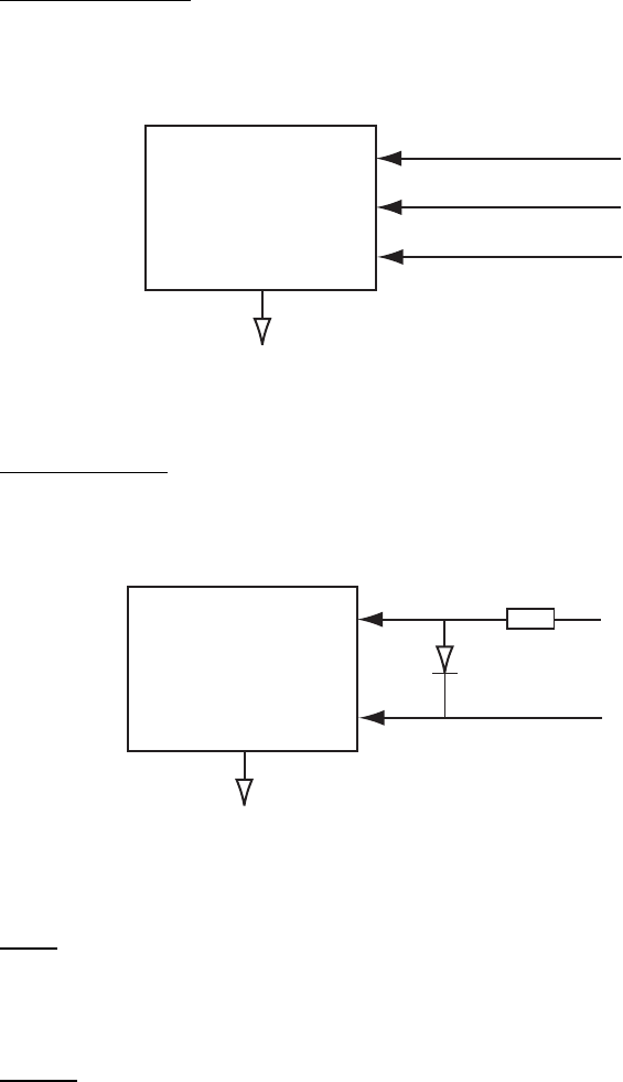
APPENDIX
AP-28
Serial interface – input ports
Heading sensor
Baud rate is selectable from 4800 bps (non-IMO only) and 38.4 kbps. Complies with IEC
61162-2.
LTC1535
Isolated RS485 Transceiver
Logical High: A-B> +0.2V
Logical Low: A-B< -0.2V
RD-A
RD-B
GND
Log/navigator
Baud rate is adaptive with RX data. Complies with IEC 61162-1.
PC-400
Photo Coupler
RD-A
RD-B
470 ohm
This port is an opticoupler used to isolate I/F terminal on RD terminal.
Absolute maximum rating
Input
Forward current: 50 mA
Reverse voltage: 6 V
Output
Supply voltage: 16 V
High level output voltage: 16 V
Low level output current: 50 mA
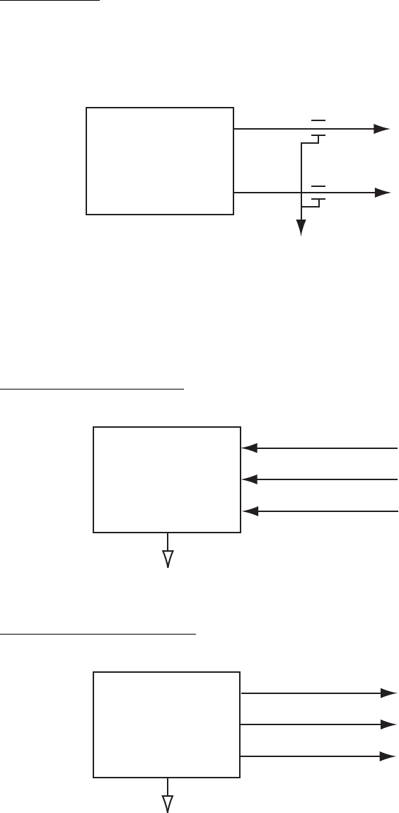
APPENDIX
AP-29
Serial interface – output ports
TT for ECDIS
Baud rate for output sentences are set on the Initial Settings menu. Complies with IEC
61162-1.
SN751178NS
Dual differrential
drivers and receivers
TD-A
TD-B
Logical High: A-B> +0.2V
Logical Low: A-B< -0.2V
=
=
Serial interface – input/output ports
Baud rate is fixed at 38.4 kbps. Complies with IEC 61162-2.
AIS Input port (RD-A, B)
LTC1535
Isolated RS485 Transceiver
Logical High: A-B> +0.2V
Logical Low: A-B< -0.2V
RD-A
RD-B
GND
AIS Output port (TD-A, B)
LTC1535
Isolated RS485 Transceiver
Logical High: A-B> +4.0V
Logical Low: A-B> -4.0V
TD-A
TD-B
GND

APPENDIX
AP-30
3. Parts Lists and Parts Location
Parts lists
Processor unit RPU-014, Control unit RCU-104/105, Display unit MU-201CR/ MU-231CR
FURUNO
Model FR-21x7/28x7 Series (incl. BB series)
Unit
ELECTRICAL PARTS LIST
SYMBOL PRINTED CIRCUIT BOARD/ REMARKS
ASSY. TYPE
PROCESSOR UNIT RPU-013
PTU Board 03P9339 AC s
p
ec.
03P9338 DC s
p
ec.
SPU Board 03P9337
HV Board HV9017
Terminal Board 03P9342
NET Board 03P9332
CONTROL UNIT RCU-014
PNL Board 03P9343
BUZ Board 03P9362
Trackball Ass
y
. TA4726N
CONTROL UNIT RCU-015
PNL Board 03P9344
Trackball Ass
y
. TA4726N
DISPLAY UNIT MU-201CR
PWR Pack RKW-12-13RE AC s
p
ec.
DC-DC Board 03P9359 DC s
p
ec.
Noise Filter CF-205A AC s
p
ec.
MXB-1206-33 DC s
p
ec.
DVI I/F Board SCBFRNB-A
INVERTER Board 201PW021-C
LCD Board 201PW023-H
LCD Unit 210NL128102AC31-02
DISPLAY UNIT MU-231CR
PCB BSM-501A
PWR Pack RKW-12-13RE AC s
p
ec.
DC-DC Board 03P9359 DC s
p
ec.
Noise Filter CF-205A AC s
p
ec.
MXB-1206-33 DC s
p
ec.
FIL Board 03P9360
INVERTER Board NA19002-4241
LCD Board NA21808
LCD Unit FLC59UXC8V-04
DVI I/F Board BSM-501A
Processor Unit RPU-013
Control Unit RCU-014
Control Unit RCU-015
Display Unit MU-201CR
Display Unit MU-231CR
2003/10

APPENDIX
AP-31
Antenna unit RSB-096/097 (for FAR-2117(-BB)/2127(-BB)/2817/2827)
FURUNO Model FAR-2117(BB)/2127(BB)/2817(BB)/2827(BB)
Unit
Antenna Unit RSB-096/097
ELECTRICAL PARTS LIST
SYMBOL NAME REMARKS
PRINTED CIRCUIT BOARD
RF 03P9349
BP 03P9347
MD 03P9244-A FAR-2117/2817
03P9244-B FAR-2127/2827
SCANNER CHASSIS
RSB-096 24 rpm
RSB-097 42 rpm
RF MODULE
RTR-078A FAR-2117/2817
RTR-079A FAR-2127/2827
MIC ASSEMBLY
RU-9601 FAR-2117/2817
RU-9603 FAR-2127/2827
MOTOR
D8G-516 24 rpm, w/capacitor
D8G-571 42 rpm, w/capacitor
DIODE LIMITER
RU-9099
FAR-2117/2127/2817/2827
CIRCULATOR
FX00-0220-00
FAR-2117/2127/2817/2827
PULSE TRANSFORMER
RT-9023 FAR-2117/2817
RT-9025 FAR-2127/2827
MAGNETRON
MAF1565N FAR-2117/2817
MG5436 FAR-2127/2827
2011/2
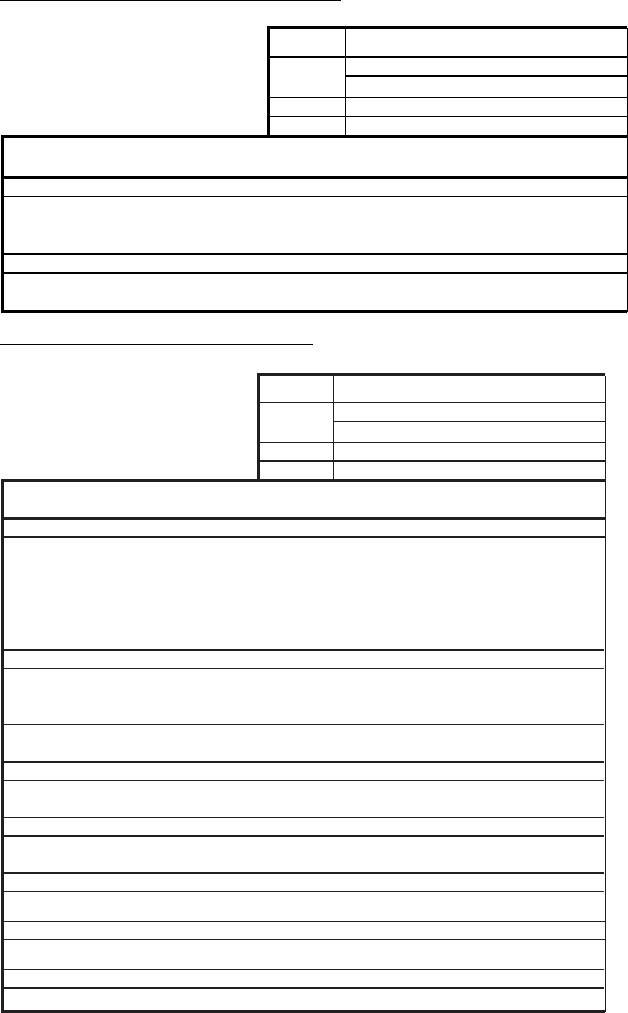
APPENDIX
AP-32
Antenna unit RSB-103/104/105 (FAR-2827W)
FURUNO
Model FAR-2827W
Unit Antenna Unit RSB-104/105
ELECTRICAL PARTS LIST
SYMBOL NAME REMARKS
PRINTED CIRCUIT BOARD
TB 03P9349
BP GEN 03P9347
MOTOR
D8G-516
2003/10
Transceiver unit RTR-081A (FAR-2827W)
FURUNO
Model
FAR-2827W
Unit
Transceiver Unit RTR-081A
ELECTRICAL PARTS LIST
SYMBOL NAME REMARKS
PRINTED CIRCUIT BOARD
TB 03P9349
IF AMP 03P9335
PWR 03P9348
MD 03P9244
RFC 03P9346
MIC ASSEMBLY
RU-9601
MOTOR
24 rpm
DIODE LIMITER
RU-9099
CIRCULATOR
FX00-0220-00
PULSE TRANSFORMER
RT-9023
MAGNETRON
MG5436
2011/2
109P0824H602
ISOLATOR
FX0157

APPENDIX
AP-33
Antenna unit RSB-098/099/100/101/102 (for FAR-2137S-BB)/2837S)
FURUNO Model FAR-2137S(BB), FAR-2837S(BB)
Unit Antenna Unit RSB-098/099
RSB-100/101/102
ELECTRICAL PARTS LIST
SYMBOL NAME REMARKS
PRINTED CIRCUIT BOARD
TB 03P9349
IF AMP 03P9335
PWR 03P9348
MD 03P9244
RFC 03P9346
SCANNER CHASSIS
RSB-098 21/26 rpm
RSB-099 21/26 rpm
RSB-100 45 rpm
RSB-101 45 rpm
RSB-102 45 rpm
RF MODULE
RTR-080
MIC ASSEMBLY
RU-9760A
MOTOR
RM-7398 RSB-098/099 21/26 rpm, 200/220V, 3
φ
RM-7435 RSB-098/099 21/26 rpm, 380/440V, 3
φ
RM-9519
RSB-100/101/102
45 rpm, 220V, 3
φ
, 50 Hz
RM-9520
RSB-100/101/102
45 rpm, 220V, 3
φ
, 60 Hz
RM-9521
RSB-100/101/102
45 rpm, 440V, 3
φ
, 60 Hz
DIODE LIMITER
RU-9426
CIRCULATOR
RC_6584S
PULSE TRANSFORMER
RT-9273
MSS MSS-7497 200/220V, 3
φ
MSS MSS-7497A 380/440V, 3
φ
MAGNETRON
MG5223F
2006/11
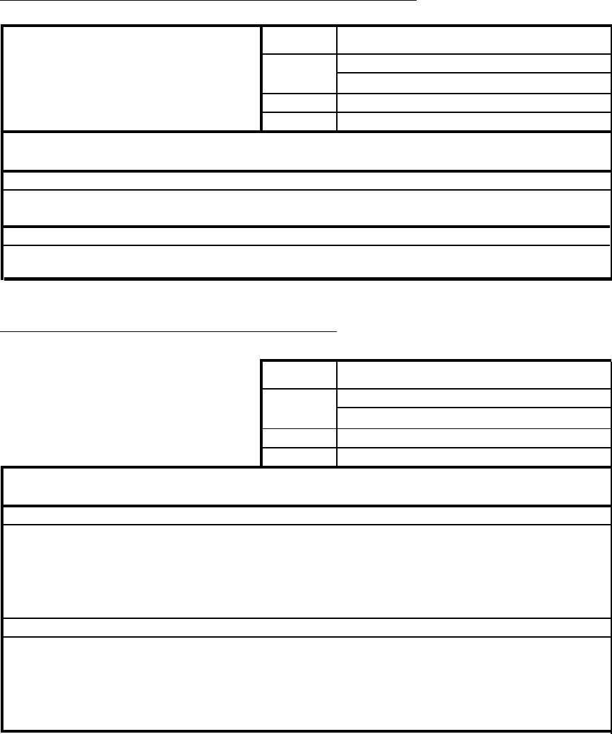
APPENDIX
AP-34
Power Supply Unit PSU-007 (for FAR-2137S(-BB)/2837S
FURUNO
Model
PSU-007
Unit
Power Supply Unit
ELECTRICAL PARTS LIST
SYMBOL NAME REMARKS
PRINTED CIRCUIT BOARD
HG3_DC12V
TB1
RELAY
2003/10
Antenna unit RSB-104/105 (for FAR-2837SW)
FURUNO Model FAR-2837SW
Unit Antenna Unit
RSB-104/105
ELECTRICAL PARTS LIST
SYMBOL NAME REMARKS
PRINTED CIRCUIT BOARD
TB 03P9349
BP GEN 03P9347
MSS MSS-7497 200/220V,
φ
3
MSS-7497-A 380/440V,
φ
3
MOTOR
RM-7398 RSB-104 21 rpm: 200 V, 3
φ
, 50 Hz
RSB-104
26 rpm: 220 V, 3
φ
, 60 Hz
RM-7345 RSB-105 21 rpm: 380 V, 3
φ
, 50 Hz
RSB-105
26 rpm: 440 V, 3
φ
, 60 Hz
2003/10

APPENDIX
AP-35
Transceiver unit RTR-082 (for FAR-2837SW)
FURUNO
Model FAR-2837SW
Unit Transceiver Unit RTR-082
ELECTRICAL PARTS LIST
SYMBOL NAME REMARKS
PRINTED CIRCUIT BOARD
TB 03P9349
IF AMP 03P9335
PWR 03P9348
MD 03P9244
RFC 03P9346
MIC ASSEMBLY
RU-9760A
MOTOR
TR LIMITER
TL378A
CIRCULATOR
RC_6584S or RC4910S
PULSE TRANSFORMER
RT-9273
MAGNETRON
MG5223F
2006/11
109P0824H602
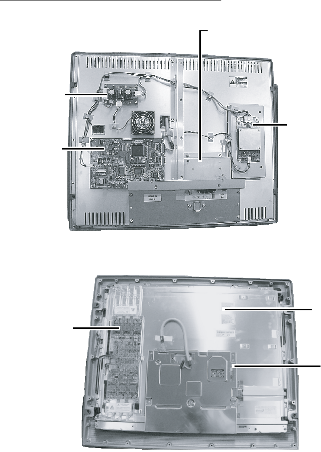
APPENDIX
AP-36
Parts location
Display unit MU-231CR (AC specification)
Noise Filter
(AC spec.: LF-205A
DC spec.: MXB-1206-33)
DC-DC Board 03P9359 (AC spec.)
(For DC spec., PWR Pack
RKW-12-13RE is used.)
FIL Board
(03P9360)
DVI I/F Board
(BSM-501A)
Display unit MU-231CR, rear cover removed
Inverter Board
(NA19002-4241)
LCD Unit
FLC59YXC8V-04
LCD Board
(NA21808)
Display unit MU-231CR, inner shield plate removed
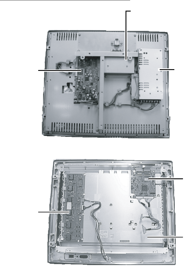
APPENDIX
AP-37
Display unit MU-201CR (DC specification)
Noise Filter
(AC spec.: LF-205A
DC spec.: MXB-1206-33)
PWR Module RKW-12-13RE
(DC spec.)
(For AC spec, DC-DC Board
03P9359 is used.)
DIV I/F Board
(SCBFNRB-A)
Display unit MU-201CR, rear cover removed
Inverter Board
(210PW021-C)
LCD Board
(201PW023-H)
LCD Unit
(NL128102AC31-02)
Display unit MU-201CR, inner shield plate removed
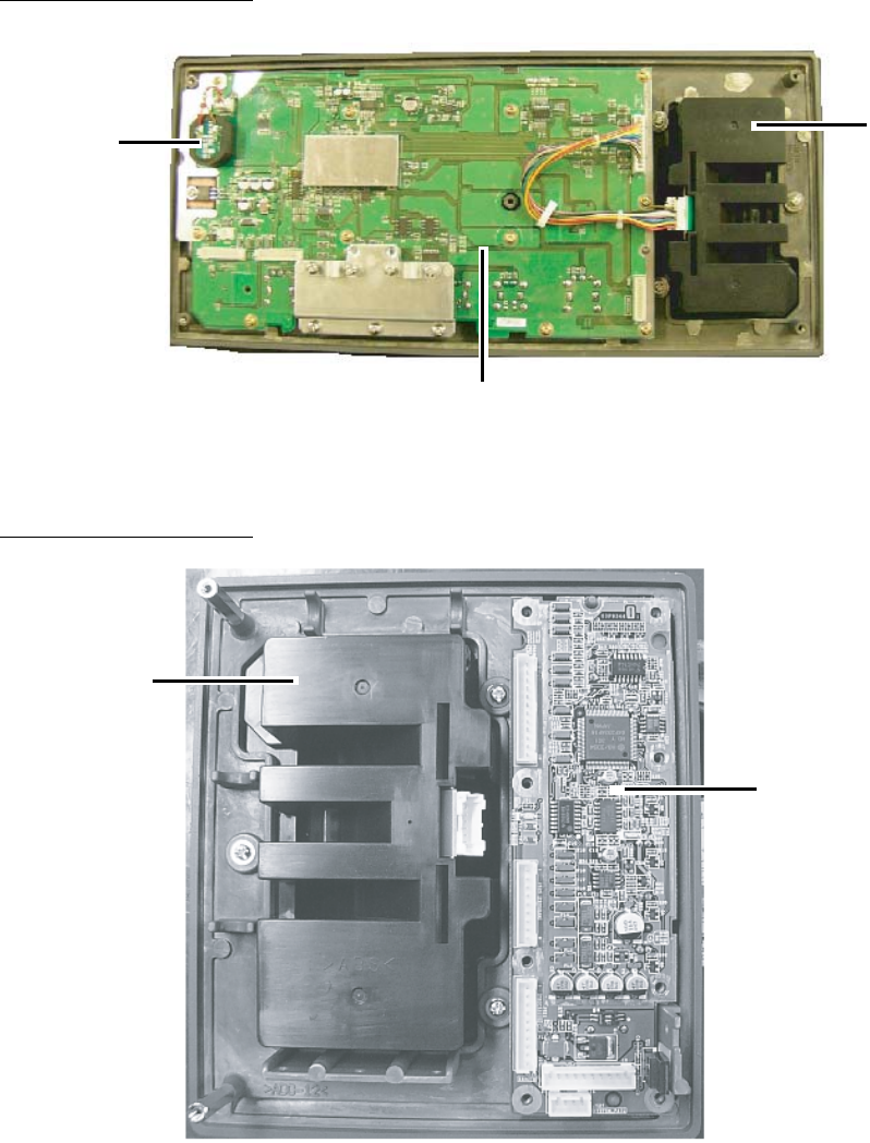
APPENDIX
AP-38
Control unit RCU-014
BUZ Board
(03P9362)
Trackball
Assy.
(TA4726N)
PNL Board
(03P9343)
Control unit RCU-014, rear cover removed
Control unit RCU-015
Trackball Assy.
(TA4726N)
PNL Board
(03P9344)
Control unit RCU-015, rear cover removed
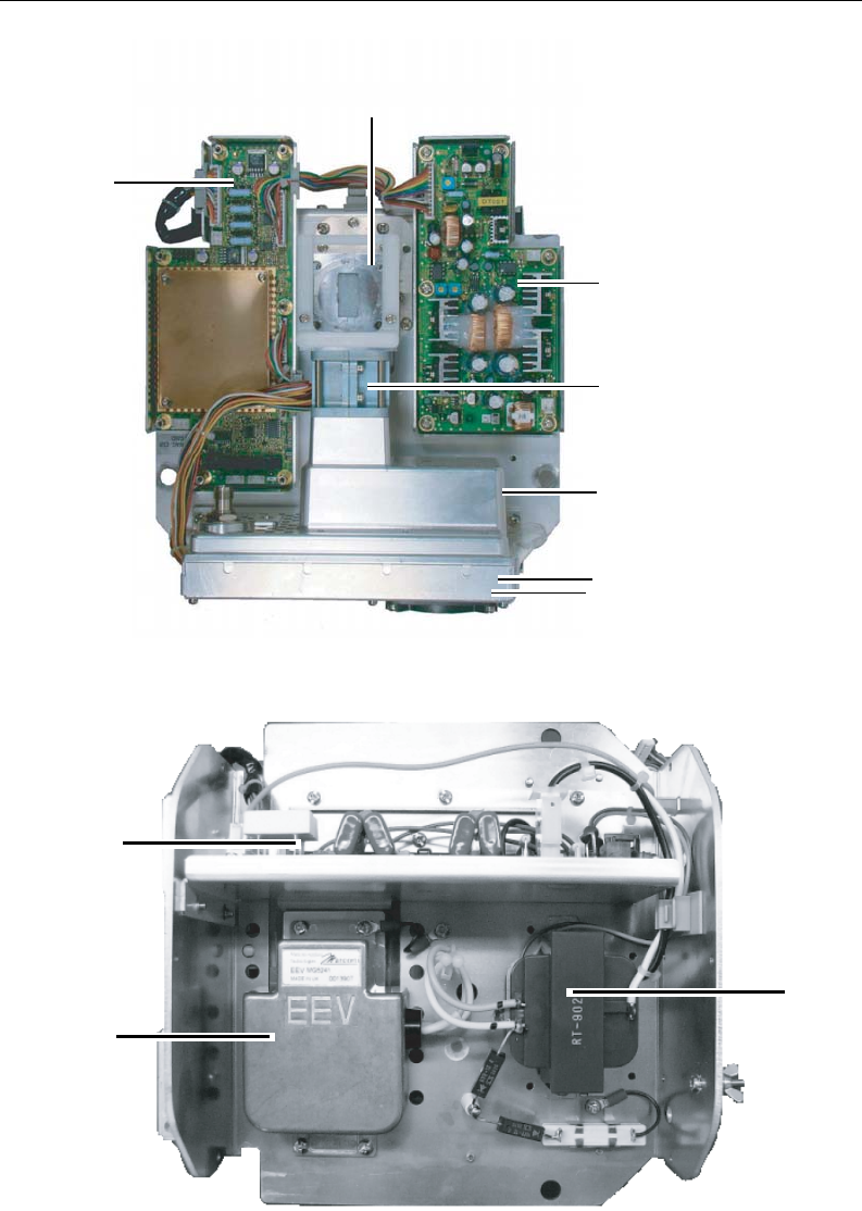
APPENDIX
AP-39
Transceiver unit RTR-078A/079A (for FAR-2117(-BB)/2127(-BB)/2817/2827
RFC Board
(03P9346)
RF PWR Board
(03P9348)
Diode Limiter
(RU-9099)
IF Board
(03P9355)
MIC Assy.
(RU-9601 (FAR-2117/2817)
RU-9603 (FAR-2127/2127-5A/2827))
Circulator
(FX00-0200-00)
Transceiver unit RTR-078A/079A (for FAR-2117(-BB)/2127(-BB)/2817/2827), upper half
MD Board
(03P9244-A)
Magnetron
(MAF1565N)
Pulse Transformer
(RT-9205)
Transceiver unit RTR-078A (for FAR-2117(-BB)/2127(-BB)/2817/2827), lower half
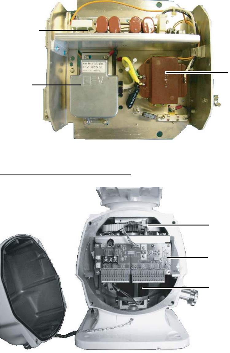
APPENDIX
AP-40
MD Board
(03P9244-B)
Magnetron
(MG5436)
Pulse Transformer
(RT-9203)
Transceiver unit RTR-079A (for FAR-2117(-BB)/2127(-BB)/2817/2827, lower half
Antenna unit RSB-103 (for FAR-2827W)
BP Board
(03P9347)
RF Board
(03P9349)
Motor
(DG8-516)
Antenna unit RSB-103 (for FAR-2827W)
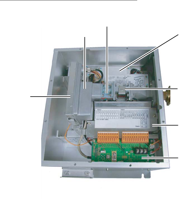
APPENDIX
AP-41
Transceiver unit RTR-081A (for FAR-2827W)
TB Board
(03P9349)
PWR Board
(03P9348)
IF Amplifier
(03P9335)
Circulator
(FX00-0220-00)
Beneath:
Isolator (FX0157)
RFC Board (03P9346)
Underneath:
MD Board (03P9244)
Pulse Converter (RT-9023)
Magnetron (MG5436)
Motor (109P0824H602)
Diode Limiter
(RU-9099)
MIC Assy.
(RU-9601)
Transceiver unit RTR-081A (for FAR-2827W), cover opened
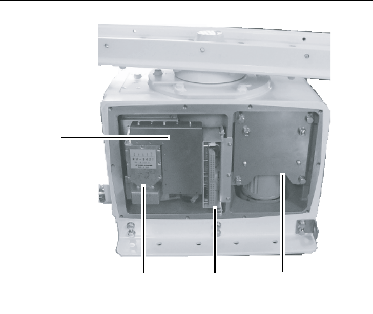
APPENDIX
AP-42
Antenna unit RSB-098/099/100/101/102 (for FAR-2137S(-BB)/2837S)
TB Board
(03P9349)
Motor
RM-7398
(RSB-098, 21/26 rpm, 200/220V, 3
φ)
RM-7435
(RSB-099, 21/26 rpm, 380/440V, 3
φ)
RM-9519
(RSB-100, 45 rpm, 220V, 3
φ
, 50 Hz)
RM-9520
(RSB-101, 45 rpm, 220V, 3
φ
, 60 Hz)
RM-9521
(RSB-102, 45 rpm, 440V, 3
φ
, 60 Hz)
MIC Assy.
(RU-9760A)
Behind plate:
Diode Limiter
(RU-9426)
Circulator
(RC-6584S
Behind plate
MSS-7497 Board
(200/220 V)
MSS-7497-A Board
(380/440 V)
Antenna unit RSB-098/099/100/101/102 (for FAR-2137S-(BB)/2837S), cover opened
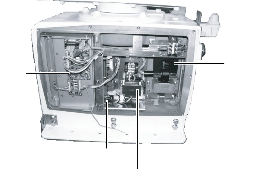
APPENDIX
AP-43
RFC Board
(03P9346)
Magnetron
(MG5223F)
MD Board
(03P9244)
Pulse Transformer
(RT-9773)
Antenna unit RSB-098/099/100/101/102 (for FAR-2137S(-BB)/2837S), cover opened
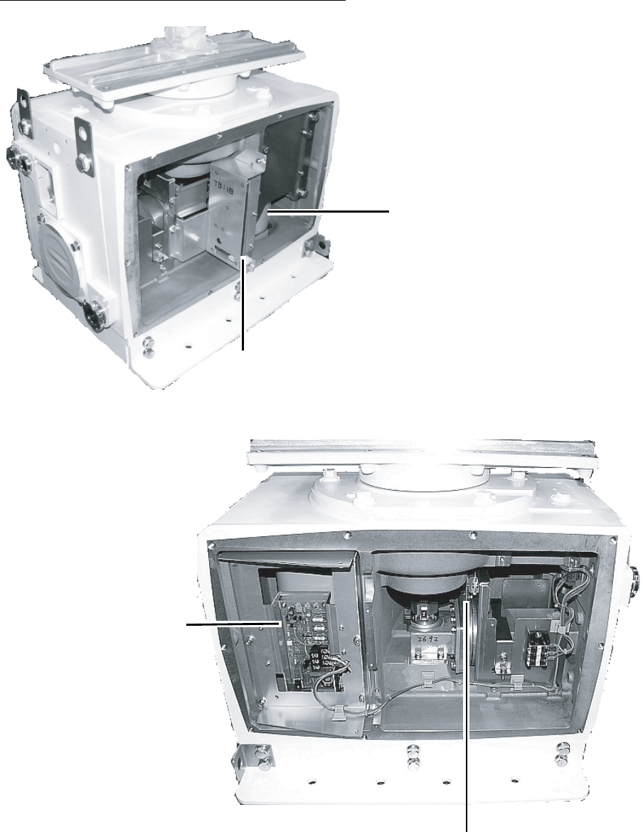
APPENDIX
AP-44
Antenna unit RSB-104/105 (for FAR-2837SW)
Motor*
* RM-7398 (For RSB-104, 21 rpm, 200 V, 3
φ
, 50 Hz;
For RSB-104, 26 rpm, 220 V, 3
φ
, 60 Hz)
RM-7345 (For RSB-105, 21 rpm, 380 V, 3
φ
, 50 Hz;
For RSB-105, 26 rpm, 440 V, 3
φ
, 60 Hz)
TB Board
(03P9349)
Antenna unit RSB-104/105 (for FAR-2837SW), cover opened
MSS Board
MSS-7497 (200/220V,
φ
3)
MSS-7497-A (380/440V,
φ
3)
BP GEN Board
(03P9347)
Antenna unit RSB-104/105 (for FAR-2837SW), cover opened
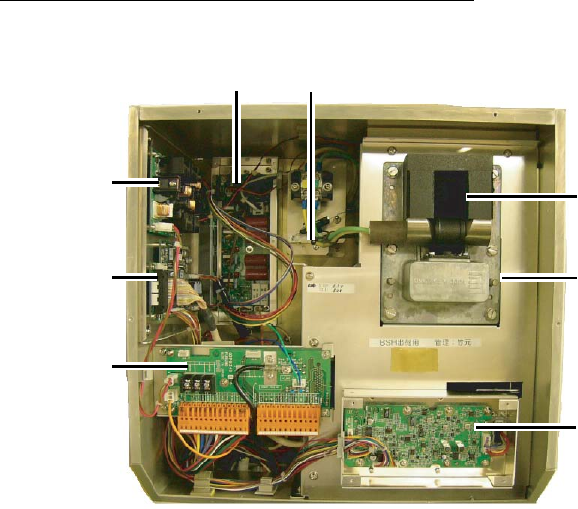
APPENDIX
AP-45
Transceiver unit RTR-082 (for FAR-2837SW)
IF Board (03P9335)
TB Board
(03P9349)
RFC Board
(03P9346)
RF PWR Board
(03P9348)
MD Board
(03P9244)
Magnetron
(MG5223F)
Beneath plate
MIC Assy. (RU-9760A)
Circulator (RC4910S)
TR Limiter (TL378A)
Fan Motor (MSS-09B24DH-R)
Pulse Transformer
(RT-9273)
Transceiver unit RTR-082 (for FAR-2837SW), cover opened
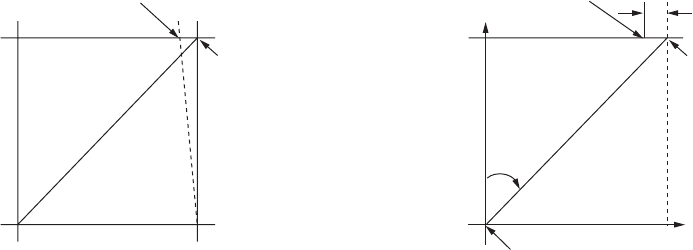
APPENDIX
AP-46
4. Longitude Error Table (on 96 nm range scale)
The longitude lines concentrate on the north pole and south pole, namely, 1 nm is
equivalent to 1 minute at 0 degree latitude, 2 minutes at 60 degrees latitude, 3 minutes at
70 degrees latitude and so on. For this reason, a longitude error occurs on the radar display.
For example, when own ship is at 60°N and 135°E, even if the cursor indication is 62°N and
139°E, the real cursor position is deviated to the left (west) side. The table below shows the
longitude error, represented from 0° to 90° at 96 nm from the radar center (own ship).
62°N°N
60°N
135°E
°E
96 nm
θ
Real cursor position
Cursor position
indicated
139°E
LAT
Real cursor position
R: Error
Cursor position
indicated
OS position
Distance error in direction of longitude due to latitude

APPENDIX
AP-47
0.2256 0.4444 0.6496 0.8350 0.9950 1.1248 1.2202 1.2786 1.2980
0.21980213 0.43290201 0.632803 0.8134132 0.96923215 1.09551918 1.1884382 1.24517456 1.26402037
0.21229339 0.41810678 0.61115946 0.78556318 0.93600295 1.05790007 1.14755221 1.20224625 1.22034042
0.20316898 0.40012949 0.58486463 0.75173456 0.89565021 1.0122297 1.09793265 1.15016811 1.16737294
0.19249832 0.37910698 0.55411863 0.71218478 0.84848102 0.95885565 1.03998717 1.08933651 1.10552105
0.18036264 0.35519924 0.51915545 0.66721485 0.79485438 0.89818413 0.97406698 1.02021439 1.03525547
0.16685429 0.32858822 0.48024119 0.61716701 0.73517843 0.83067689 0.90076355 0.94332783 0.95711098
0.15207608 0.29947644 0.437672 0.56242216 0.66990732 0.7568477 0.82060477 0.85926197 0.87168229
0.13614047 0.26808546 0.39177186 0.53339693 0.59953781 0.67725844 0.73420069 0.76865661 0.77961957
0.11916876 0.2346542 0.3428901 0.44054055 0.52460545 0.59251483 0.6422089 0.67220131 0.68162348
0.10129001 0.19943707 0.29139874 0.37433139 0.44568053 0.50326182 0.54532952 0.57063015 0.57843983
0.08264056 0.16270211 0.23768966 0.30527334 0.36336372 0.41017869 0.44429984 0.46471615 0.47085389
0.06336208 0.12472888 0.18217162 0.23389198 0.27828148 0.31397386 0.33988878 0.35526538 0.35968447
0.04360137 0.0858064 0.12526714 0.16073056 0.19108136 0.21537949 0.23289096 0.24311083 0.24577764
0.02350833 0.04623087 0.0674093 0.08634588 0.10242699 0.11514595 0.1241207 0.12910605 0.13000029
0.00323737 0.0063035 0.00903844 0.01130406 0.01299309 0.01403609 0.0144058 0.0141187 0.01323356
1.2780 1.2192 1.1233 0.9933 0.8332 0.6479 0.4431 0.2249 0
1.24442563 1.18701379 1.09356117 0.96694117 0.81103484 0.3061092 0.43117887 0.21881975 0
1.20131324 1.14577786 1.05546143 0.93315023 0.78260251 0.60843159 0.41596331 0.21107193 0
1.14905813 1.09582188 1.00932899 0.89225746 0.74821409 0.58162173 0.397582 0.20171772 0
1.08805799 1.03752602 0.95551494 0.84457408 0.70813132 0.55038538 0.37617487 0.19082831 0
1.0187708 0.97133397 0.89442885 0.79046297 0.66265924 0.51496026 0.35190481 0.17848659 0
0.94174265 0.89774948 0.82653562 0.73033596 0.61214392 0.47561599 0.32495654 0.16478648 0
0.85754099 0.81733258 0.75235195 0.66465066 0.55696981 0.43265198 0.29553516 0.14983224 0
0.76681293 0.73069528 0.63744242 0.59390696 0.49755683 0.38639524 0.26386458 0.13373769 0
0.67024897 0.63849695 0.58741521 0.51864327 0.43435714 0.33719779 0.23018583 0.11662531 0
0.568584 0.54143927 0.49791741 0.43943239 0.36785173 0.28543407 0.19475522 0.09862535 0
0.46259176 0.44026091 0.40463016 0.35687717 0.29854675 0.23149802 0.15784242 0.07987479 0
0.35307892 0.3357319 0.30826343 0.2716059 0.22696965 0.17580013 0.11972833 0.06051633 0
0.2487894 0.22864776 0.20955062 0.18426754 0.15366517 0.1187643 0.08070304 0.0406973 0
0.12684572 0.11982348 0.10624302 0.09552679 0.0791912 0.04106355 0.04106355 0.02056855 0
0.01184713 0.01008727 0.008104 0.00605903 0.00411455 0.00111154 0.00111154 0.00028325 0
75°
70°
65°
60°
55°
50°
45°
40°
35°
30°
25°
20°
15°
10°
5°
0°
75°
70°
65°
60°
55°
50°
45°
40°
35°
30°
25°
20°
15°
10°
5°
0°
5
°
10
°
15
°
20
°
25
°
30
°
35
°
40
°
45
°
50
°
55
°
60
°
65
°
70
°
75
°
80
°
85
°
90
°
LAT
θ
LAT
θ
(nm)
(nm)

APPENDIX
AP-48
5. Abbreviations
Word Abbreviation Word Abbreviation
Acknowledge ACK Marker MKR
Acquire, Acquisition ACQ Marker MARK
Acquisition Zone AZ Master MASTER
Adjust, Adjustment ADJ Master MSTR
Aft AFT Maximum MAX
Alarm ALARM May MAY
Anchor Watch ANCH Medium Pulse MP
Antenna ANT Medium Pulse PULSE M
Anti Clutter Rain RAIN Menu MENU
Anti Clutter Sea SEA Minimum MIN
Automatic AUTO Minute(s) min
Automatic Identification System AIS Nautical Mile(s) NM
Bearing BRG Navigation NAV
Bow Crossing Range BCR Night NIGHT
Bow Crossing Time BCT Night NT
Brilliance BRILL Normal NORM
Clear CLR Normal NORMAL
Closest Point of Approach CPA North N
Consistent Common Reference Point CCRP North NORTH
Contrast CONT North Up N UP
Contrast CONTRAST North Up NORTH UP
Course CRS November NOV
Course Up C UP October OCT
Course Up COURSE UP Off OFF
Course Over the Ground COG Offset OFFSET
Course Through the Water CTW On ON
Cursor CURS Out/Output OUT
Date DATE Own Ship OS
Day DAY Panel Illumination PANEL
December DEC Parallel Index Line PI
Destination DEST Past Positions PAST POSN
Delay DELAY Performance Monitor MON
Delete DEL Performance Monitor PM
Delete DELETE Port/Portside PORT
Depth DEPTH Position POSN
Depth DPTH Power PWR
Destination DESTINATION Predicted PRED
Differential GPS DGPS Rain RAIN
Display DISP Range RNG
Drift DRIFT Range Rings RING
East E Range Rings RR
Echo Reference REF Rate Of Turn ROT
Electronic Bearing Line EBL Real-time Kinemetic RTK
East E Reference REF
Enter ENT Relative REL

APPENDIX
AP-49
Enter ENTER Map(s) MAP
Error ERR March MAR
Error ERROR Maritime Mobile Services Identity number MMSI
Estimated Time of Arrival ETA Relative Motion RM
External EXT Revolutions Per Minute RPM
Fathom(s) fm Route ROUTE
February FEB S-Band S-BAND
Feet/Foot ft Search And Rescue SAR
Full FUL Search And Rescue Transponder SART
Full FULL Second(s) SEC
Gain GAIN Select SEL
Global Positioning System GPS Ship's Time TIME
Grid GRID Short Pulse SP
Ground GND Short Pulse PULSE S
Guard Zone GUARD Speed SPD
Guard Zone GZ Speed Over the Ground SOG
Gyro GYRO Speed Through the Water STW
Head Up H UP Stabilized STAB
Head Up HEAD UP Standby STBY
Heading HDG Starboard/Starboard Side STBD
Heading Line HL Starboard/Starboard Side STAR BORD
Information INFO Symbol(s) SYM
Information INFO Symbol(s) SYMBOL
In IN Target TGT
Indication IND Target Tracking TT
Initialisation INI Test TEST
Initialisation INITIALIZE Time TIME
Integrated Navigation System INS Time to CPA TCPA
Interference Rejection INT REJECT Time To Go TTG
Interference Rejection IR Track TRK
Interval INT Tracking TRKG
Interval INTERVAL Trail(s) TRAIL
January JAN Trial TRIAL
July JUL Transmit TX
June JUN Trigger Pulse TRIG
Kilometre km Trigger Pulse TRIGGER
Knot(s) kn Tune TUNE
Latitude LAT True T
Latitude/Longitude L/L True Motion TM
Limit LIM Universal Time, Coordinated UTC
Line HL Variable Range Marker VRM
Log LOG Vector VECT
Long Pulse LP Video VID
Long Pulse PULSE L Voyage VOY
Longitude LON Voyage Data Recorder VDR
Lost Target LOST TGT Warning WARNING
Magenta MAG Waypoint WPT
Man Overboard MOB X-Band X-BAND
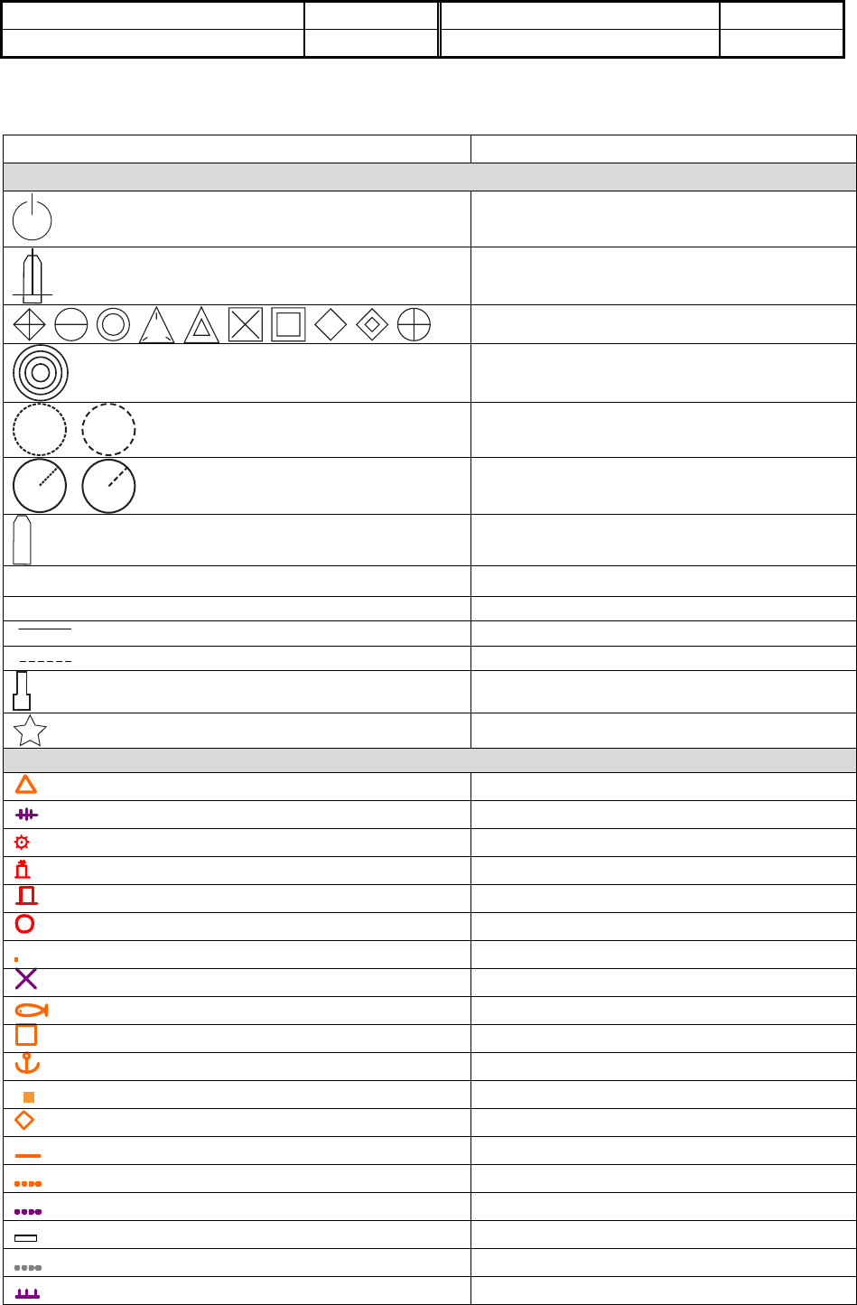
APPENDIX
AP-50
Manual MAN
Manual MANUAL
6. Symbols
Symbol Name
Radar symbols, general
(on power switch)
Power symbol
X
Own ship marker
Origin marks
Fixed range rings
Variable Range Markers
(from left, VRM1, VRM2)
Electronic Bearing Lines
(from left EBL1, EBL2)
OS mark
+ Cursor
| Heading line
North marker
Stern marker
Barge icon
Drop mark
Radar map symbols, B, C and W type radars
Mark
Danger Highlight
Buoy
Buoy
Buoy
Buoy
Buoy
Danger Highlight
Mark
Mark
Mark
Mark
Mark
Mark
Mark
Nav Line (map)
Coastline
Contour
Prohibited Area
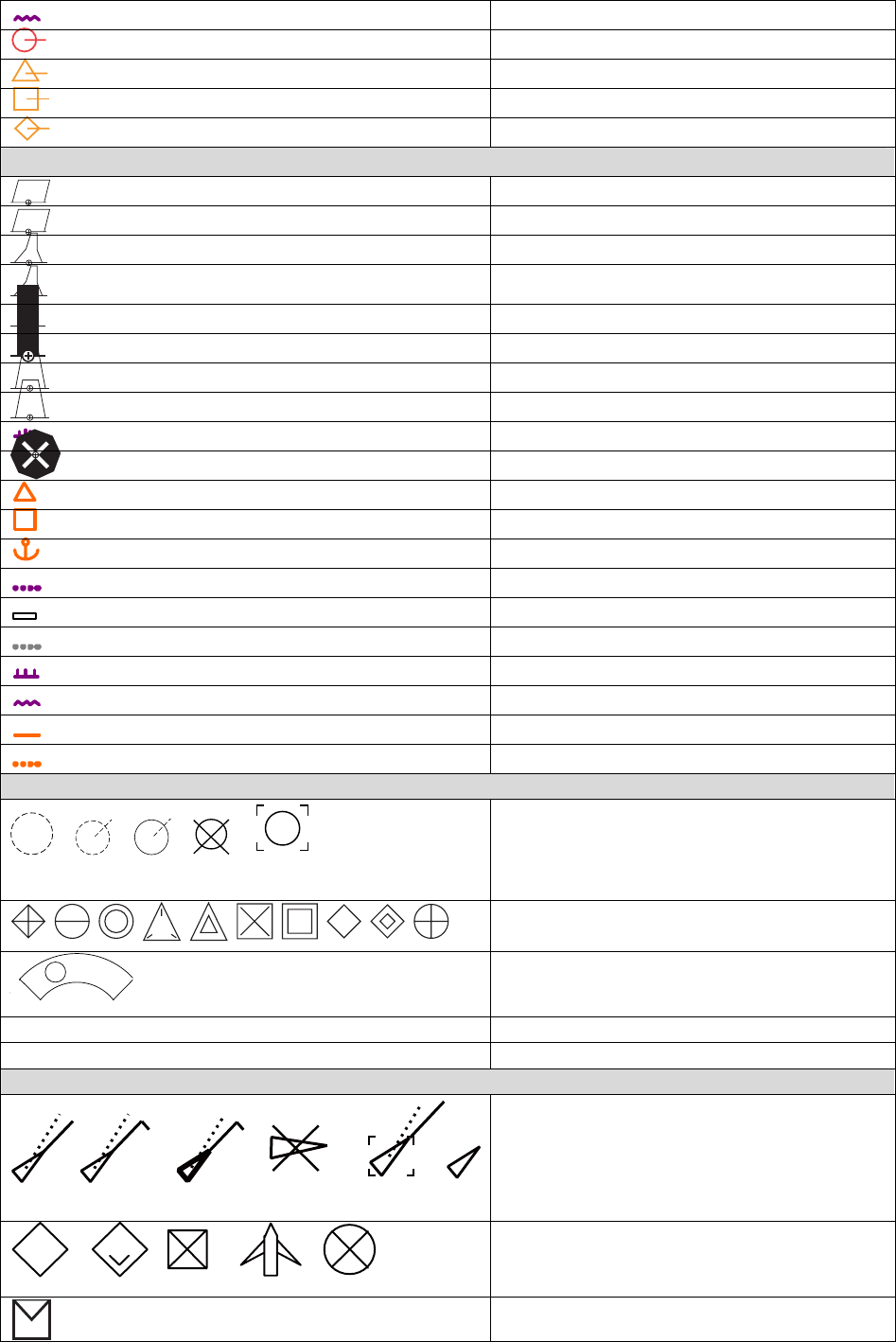
APPENDIX
AP-51
(cable) Danger Highlight
(w/line) Buoy
(w/line) Mark
(w/line) Mark
(w/line) Mark
Radar map symbols, IMO and A type radars
Red Buoy
Green Buoy
Red Buoy
Green Buoy
Red Buoy
Green Buoy
Red Buoy
Green Buoy
Purple Danger Highlight
Purple Danger Highlight
Orange Mark
Orange Mark
Orange Mark
Purple Navline (map)
White Coastline
Gray Contour Line
Purple Danger Highlight
Purple (cable) Danger Highlight
Orange Mark
Orange Mark
TT symbols
Acquired targets (from left, initial
acquisition, one minute after
acquisition, steady tracking, lost target,
target selected for data readout)
TT symbols (user may change TT
symbol)
Acquisition zone
T Trial maneuver
S Performance test
AIS symbols
A
AIS symbols (from left, activated target,
ROT higher than preset ROT,
dangerous target, lost target, target
selected for data display, sleeping
target)
+ +
Other AIS symbols (from left, real AIS
AtoN, Virtual AIS AtoN, base station,
airborne SAR aircraft, AIS SART)
AIS message received
APPENDIX
AP-52
This page intentionally left blank.
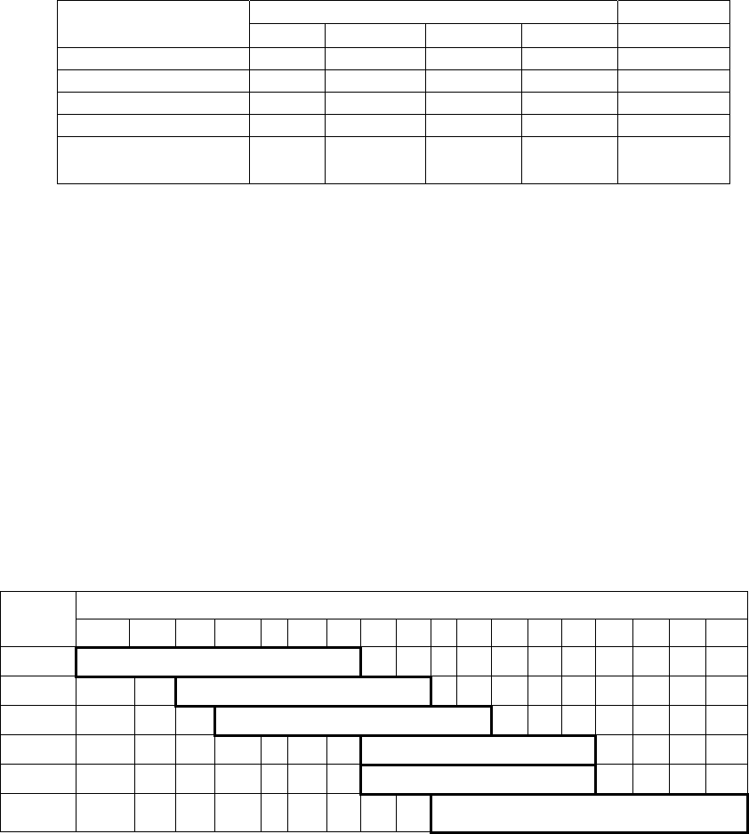
FURUNO
FAR-21x7(-BB)/28x7 SERIES
SP - 1 E3519S01L-P
SPECIFICATIONS OF MARINE RADAR/ARPA
FAR-21x7(-BB)/28x7 SERIES
1. ANTENNA RADIATORS
1. Type Slotted waveguide array
2. Beam width and sidelobe attenuation
X-band S-band
Radiator type XN5A XN12AF XN20AF XN24AF SN36AF
Length 10 ft 4 ft 6.5 ft 8 ft 12 ft
Beam width(H) 0.75° 1.8° 1.23° 0.95° 1.8°
Beam width(V) 20° 20° 20° 20° 25°
Sidelobe within ±10° -26 db -24 db -28db -28 db -24 db
Sidelobe outside
±10° -30 db -30 db -32 db -32 db -30 db
3. Polarization Horizontal
4. Rotation FAR-2117/2117-BB/2127/2127-BB/2827: 24 rpm or 42 rpm
FAR-2137S/2137S-BB/2837S: 21 rpm (50 Hz)/26 rpm (60 Hz)/
45 rpm (HSC)
FAR-2827W: 24 rpm
FAR-2837SW: 21 rpm (50 Hz), 26 rpm (60 Hz), 45 rpm (HSC)
5. Wind tolerance Relative wind 100 kt
6. De-icer (option) On: When temperature goes down to +5°C
Off: When temperature goes up to +12°C
2. RF TRANSCEIVER
1. Frequency X-band: 9410 MHz ±30 MHz, S-band: 3050 MHz ±30 MHz
2. Output power FAR-2117/2117-BB/2817: 12 kW
FAR-2127/2127-BB/2827/2827W: 25 kW
FAR-2137S/2137S-BB/2837S/2837SW: 30 kW
3. Range, pulse repetition frequency (PRF), pulselength
Range
PRF
Freq
(Hz) 0.125 0.25 0.5 0.75 1 1.5 2 3 4 6 8 12 16 24 32 48 96 120
3000* 0.07µs
3000* 0.15µs
1500 0.3µs
1000 0.5µs
1000 0.7µs
600
(500**) 1.2µs
1, 2, 4, 8, 16, 32, 120 nm ranges not available on IMO radar.
* 32 nm w/TT: 2200 Hz ** For 96 nm
4. IF 60 MHz
5. Noise figure 6 dB (typical)
6. Duplexer Ferrite circulator with diode limiter for
FAR-2117/2117-BB/2127/2127-BB/2137S/2137S-BB/
2817/2827/2837S
Ferrite circulator with TR limiter for FAR-2837SW

FURUNO
FAR-21x7(-BB)/28x7 SERIES
SP - 2 E3519S01L-P
3. DISPLAY UNIT
1. Screen Raster scan, daylight bright, yellow or green echoes in 32 levels
2. Scanning Non-interlace at 64 kHz horizontal, 60 Hz vertical
3. Display
FAR-21x7
series
FAR-21x7
series
FAR-21x7
series
FAR-28x7
series
Size, model 17-inch color
LCD, MU-170C
19-inch color
LCD, MU-190
20.1-inch color
LCD, MU-201CR
23.1-inch color
LCD
,
MU-231/231CR
Display area
(mm)
338 x 270 376.32 x 301.06 399.36 x 319.49 470.4 x 352.8
Resolution 1280 x 1024
pixels
1280 x 1024
pixels
1280 x 1024
pixels
1600 x 1200
pixels
Effective
radar
diameter
260 mm
(H: 64 kHz;
V: 60 Hz)
290 mm
(H: 64 kHz;
V: 60 Hz)
308 mm
(H: 64 kHz, V: 60
Hz)
340 mm
(H: 75 kHz, V: 60
Hz)
Viewable
range
920 mm 1020 mm 1080 mm 1200 mm
4. Minimum range Minimum range: 20 m w/raw video, + 0-2 m w/digitize error
5. Range discrimination Range discrimination: 20 m w/raw video, + 0-6 m w/digitize error
6. Range scales (nm), ring interval
Range (nm) 0.125 0.25 0.5 0.75 1.5 3 6 12 24 48 96
Ring interval (nm) 0.025 0.05 0.1 0.25 0.25 0.5 1 2 4 8 16
No. of rings 5 5 5 3 6 6 6 6 6 6 6
7. Range accuracy Within 1%
8. Bearing discrimination 0.98° (XN5A), 2.1° (XN12AF), 1.5° (XN20AF), 1.2° (XN24AF),
2.0° (SN36AF)
9. Bearing accuracy ±1°
10. Presentation mode Head-up, Head-up TB, North-up, Course-up, True Motion (sea or
ground stabilization)
11. Target tracking (TT)
Auto or Manual acquisition: 100 targets in 0.2-24(32) nm
Auto tracking on all acquired targets
12. Radar map Nav lines, coastlines, buoys, etc. produced by operator. 20,000 pts
in radar mode, 6000 pts on IC card in chart mode
13. Acquisition zone AZ1: 0.5 nm width sector, within 3-6 nm, desired bearing
AZ2: 1 nm width sector or polygon, desired range and bearing
14. Parallel index line Choice of 1, 2, 3 or 6 lines
15. AIS IMO SN Circ.217, IEC 62388
16. Chart cards FURUNO and NAVIONICS
4. INPUT/OUTPUT
1. Heading signal input - Synchro signal (20-100 VDC, 20-135 VAC 50/60/400/500 Hz),
- Stepper signal (20-100 V)
- AD-10 format
2. Speed log IEC 61162-1
3. AIS data (IEC 61162-2) VDM, VDO, ALR
4. Input data sentences (IEC 61162-1)
BWC, BWR, DBS, DBT, DPT, DTM, GGA, GLL, HDT, RMA, RMB,
RMC, RTE, VBW, VDR, VHW, VTG, VWT, MTW, MWV, WPL, ZDA
5. Output data sentences (IEC 61162-1)
TLL, RSD, TTM, OSD, ESP

FURUNO
FAR-21x7(-BB)/28x7 SERIES
SP - 3 E3519S01L-P
5. POWER SUPPLY
1. Display unit 24 VDC or 100-230 VAC, 1ø, 50/60 Hz
FAR-21x7: 24 VDC, 2.3 A; 100-230 VAC, 0.7A (100 V)
FAR-28x7: 24 VDC, 3.2 A; 100-230 VAC, 0.9 A (100 V)
440 VAC, 1 ø, 50/60 Hz with optional transformer RU-1803
2. Processor unit FAR-2117/2817/2117-BB:
24VDC: 7.6A (8.5A), 100-115 VAC: 2.6A (3.0A),
220-230 VAC: 1.6A (1.7A)
FAR-2127/2827/2127-BB:
24 VDC: 8.8A (9.7A), 100-115 VAC: 3.0A (3.4A),
220-230 VAC: 1.8A (1.9A)
( ): Value for 42 rpm antenna unit
FAR-2827W:
100-115 VAC: 3.2A, 220-230 VAC: 1.6A
FAR- 2137S/2137S-BB/2837S/2837SW:
100-115 VAC: 3.0A, 220-230 VAC: 1.5A
3. Antenna unit S-band: 200/220/380/440 VAC, 3ø, 50/60 Hz
Antenna voltage input (100 kt) Model
200 VAC,
ø3, 50 Hz,
220 VAC,
ø3, 60 Hz
380 VAC,
ø3, 50 Hz,
440 VAC,
ø3, 60 Hz
220 VAC,
ø3, 50 Hz
(HSC)
220 VAC,
ø3, 60 Hz
(HSC)
440 VAC,
ø3, 60 Hz
(HSC)
FAR-2137S(BB) 3.0 A 1.5 A 3.5 A 3.5 A 1.7 A
FAR-2837S 3.0 A 1.5 A 3.5 A 3.5 A 1.7 A
FAR-2837SW 3.0 A 1.5 A - - -
FAR-2137SW 3.0 A 1.5 A - - -
4. Console 115/230 VAC, 1ø, 50/60 Hz, 440 VAC, 1ø, 50/60 Hz (with optional
transformer RU-1803)
6. ENVIRONMENTAL CONDITIONS
1. Ambient temperature
Display unit/monitor/processor unit/control unit/power supply unit/transceiver unit
-15°C to +55°C
Antenna unit -25°C to +55°C (storage +70°C)
2. Relative humidity less than 95% at 40°C
3. Waterproofing
Display unit/processor unit/control unit/power supply unit:
Front panel: IP56, Rear panel: IP20
Antenna unit: IPX6
4. Vibration 2 Hz-5Hz to 13.2 Hz: Amplitude: ±1 mm ±10%
13.2 Hz to 100 Hz: Max. acceleration 7m/s2, fixed
7. COLOR
1. Display unit Chassis: 2.5GY5/1.5, Panel: N3.0 (fixed)
Monitor N2.5 (fixed)
2. Processor unit 2.5GY5/1.5
3. Control unit N3.0 (fixed)
4. Antenna unit N9.5 (fixed)
5. Power supply unit 2.5GY5/1.5

FURUNO
FAR-21x7(-BB)/28x7 SERIES
SP - 4 E3519S01L-P
8. PERFORMANCE MONITOR
PM-31 (X-band)
1. Frequency range 9370 to 9450 MHz
2. Input power Min.: +8 dBm, Max.: +28 dBm
3. Power output (2nd pulse max output) -36 dBm
4. Power output (2nd pulse min output) -56 dBm
5. Step levels (1st pulse to 2nd pulse) 7.5 to 10.5 dB
PM-51 (S-band)
1. Frequency range 3020 to 3080 MHz
2. Input power Min.: -5 dBm, Max.: +15 dBm
3. Power output (2nd pulse max output) -15 dBm
4. Power output (2nd pulse min output) -35 dBm
5. Step levels (1st pulse to 2nd pulse) 9.0 to 11.0 dB
9. SWITCHING HUB HUB-100
1. Access Format CSMA/CD
2. Switching Format Store and Forward
3. Transmission Speed Half-duplex: 10 Mbps/100 Mbps
Full-duplex: 20 Mbps/200 Mbps
4. Necessary Cabling 10BASE-T: Category 3 or higher STP cable
100 BASE-TX: Category 5 or higher STP cable
5. Max. Cable Length 100 m
6. Ports 8 ports
- All ports auto-MDIX compliant (straight or cross cable,
automatic recognition)
- All ports EMC compliant (STP cable port)
- All ports equipped with 3 LED injectors
(Link/Act, Full-duplex/Collision, 100 Mbps/10 Mbps)
7. Buffer Memory SRAM buffer
8. MAC Address Table 1024
9. Environmental Conditions
Ambient Temperature -15 to +50°C
Relative Humidity 95% (at 40°C)
EMC IEC 60945
Waterproofing IPX0
10. Power and Power Consumption
Power 100-230 VAC
Power Consumption 100mA/100 VAC
11. Coating and Color N3.0

IN-1
INDEX
2
2nd-trace echo rejector ....................... 1-74
A
A/C RAIN adjustment
auto................................................. 1-29
manual............................................ 1-29
A/C SEA adjustment
automatic........................................ 1-28
manual............................................ 1-27
method............................................ 1-27
A/C SEA box ...................................... 1-27
Abbreviations .................................. AP-48
Acquisition zone (TT)
acknowledging................................ 3-23
activating ........................................ 3-22
deactivating .................................... 3-23
reference ........................................ 3-24
shape.............................................. 3-24
sleeping .......................................... 3-23
AIS
activating targets, all......................... 4-5
activating targets, automatically ..... 4-18
activating targets, manually.............. 4-5
AIS DISP box.................................... 4-2
association ..................................... 4-19
collision alarm................................. 4-17
controls............................................. 4-1
detailed target data......................... 4-10
display criteria .................................. 4-4
lost target........................................ 4-14
messages, alarm messages........... 4-25
messages, creating ........................ 4-22
messages, displaying automatically4-25
messages, saving........................... 4-22
messages, system.......................... 4-26
messages, transmitting .................. 4-23
messages, viewing manually.......... 4-24
past position display plotting
interval ........................................ 4-12
past position points......................... 4-13
ROT setting .................................... 4-16
sleeping a target ............................... 4-6
symbol brilliance..............................4-11
symbol color ....................................4-11
symbol size......................................4-11
system messages .......................... 4-26
target data ........................................ 4-9
turning on/off .................................... 4-2
AIS DISP box....................................... 4-2
ALARM ACK box ...................... 1-40, 3-23
ALARM ACK key................................ 1-40
ALARM box........................................ 1-39
Alarms
description...................................... 1-84
list ................................................... 1-87
output ............................................. 1-88
primary ........................................... 1-89
Alert box............................................. 1-83
Anchor watch ................................... 1-102
Antenna
information...................................... 1-90
selection ......................................... 1-91
ANTENNA box ................................... 1-90
AZ box................................................ 3-22
B
Barge marker ..................................... 1-61
Battery replacement............................. 6-4
Bearing measurement ....................... 1-34
BRILL box ...........................................1-11
BRILL control ......................................1-11
Brilliance
monitor ............................................1-11
screen data..................................... 1-75
C
CCRP................................................. 1-99
COG.......................................... 1-22, 3-20
Collision alarm
AIS.................................................. 4-17
TT ................................................... 3-21
Colors................................................. 1-97
Control description............................... 1-4
Control unit........................................... 1-3
Course-up mode ................................ 1-18
CPA AUTO ACTIVATE box ................ 4-17
CPA LIMIT box .......................... 3-21, 4-17
CU/TM RESET box............................ 1-21
CU/TM RESET key............................ 1-21
INDEX
IN-2
CURSOR DATA box ...........................1-93
CURSOR menu..................................1-10
D
Dangerous target..................................4-5
Data sentences
input ............................................... AP-9
output ........................................... AP-24
Diagnostics
radar................................................6-10
TT....................................................3-30
Digital interface.................................. AP-8
DISPLAY MODE box ..........................1-12
DRIFT box ..........................................3-20
Drop mark
activating.......................................1-103
erasing ..........................................1-104
inscribing.......................................1-104
E
EBL
bearing measurement with .............1-34
reference.........................................1-35
EBL box ..............................................1-34
EBL offset
assessing risk of collision ...............1-36
measuring range and bearing
between two targets ....................1-38
reference for origin point.................1-37
EBL OFFSET key ......................1-36, 1-38
EBL ON, EBL OFF keys .....................1-34
Echo averaging...................................1-44
Echo stretch........................................1-43
F
False echoes ........................................2-3
Function keys .....................................1-68
Fuse replacement.................................6-4
G
GAIN box ............................................1-26
GAIN control .......................................1-26
Guidance box .......................................1-7
Gyro readout.......................................1-16
H
HDG box.............................................1-16
HDG menu..........................................1-16
Heading line........................................1-59
Head-up mode....................................1-18
Head-up true bearing mode ...............1-19
HL OFF box........................................ 1-59
HL OFF key ........................................ 1-59
I
INDEX LINE key................................. 1-52
INS marker ......................................... 1-61
Interference rejector ........................... 1-43
K
Key beep ............................................ 1-82
L
LOST TARGET ALARM box........3-9, 4-15
Lost target filter (AIS) ......................... 4-14
Lost target filter (TT)............................. 3-9
M
Main menu............................................ 1-5
Maintenance
battery replacement.......................... 6-4
fuse replacement .............................. 6-4
parts replacement ............................. 6-3
periodic ............................................. 6-2
trackball ............................................ 6-5
MARK box .......................................... 1-55
MENU box ............................................ 1-6
Menu tree .......................................... AP-1
MODE key .......................................... 1-17
N
Nav data ............................................. 1-77
Net cursor
activating....................................... 1-106
adjustment of ................................ 1-107
Noise rejector ..................................... 1-45
North marker ...................................... 1-59
North-up mode ................................... 1-19
O
OFF CENTER key.............................. 1-42
Off centering....................................... 1-42
Origin marks
entering........................................... 1-55
erasing ............................................ 1-57
stabilization ..................................... 1-57
OS POSN box .................................... 1-72
Own ship marker ................................ 1-96
Own ship symbol................................ 1-60
Own ship vector.................................. 1-82
P
Parts list........................................... AP-32
INDEX
IN-3
Parts location .................................. AP-38
Past position display
AIS.................................................. 4-12
PI line boxes....................................... 1-52
PI lines
displaying, erasing.......................... 1-52
interval............................................ 1-53
number of lines............................... 1-54
orientation.............................. 1-53, 1-54
reference ........................................ 1-53
resetting.......................................... 1-54
PICTURE box..................................... 1-64
Picture setup
choosing ......................................... 1-64
default settings ............................... 1-66
disabling unnecessary.................... 1-67
user programming .......................... 1-64
user settings ................................... 1-66
Position .............................................. 1-72
POWER switch .................................... 1-1
Presentation mode
choosing ......................................... 1-17
description ...................................... 1-18
PRESENTATION MODE box ............. 1-17
Pulselength ........................................ 1-24
PULSELENGTH box.......................... 1-25
Q
Quick start............................................ 1-2
R
RACON ................................................ 2-8
Range
choosing ......................................... 1-23
measurement ................................. 1-31
RANGE box........................................ 1-23
RANGE key........................................ 1-23
Range ring.......................................... 1-31
Reference position ............................. 1-99
S
SART.................................................... 2-5
Scrollwheel drive................................ 1-82
Second-trace echo rejector................ 1-74
Sensitivity........................................... 1-26
Serial interface
input ports.................................... AP-30
output ports.................................. AP-31
Set and drift........................................ 3-20
SET box ............................................. 3-20
Shuttle ferry........................................ 1-82
SOG .......................................... 1-22, 3-20
SPD box............................................. 1-22
Speed
automatic input............................... 1-22
echo-referenced input ...................... 3-3
manual input................................... 1-23
SPEED menu..................................... 1-22
STBY/TX key ....................................... 1-1
Stern marker ...................................... 1-59
Stern-up mode
description...................................... 1-20
enabling, disabling ......................... 1-82
Sub monitor...................................... 1-105
Switching Hub HUB-100 .................. 1-101
Symbols ...........................................AP-49
T
Target alarm
acknowledging offending target ..... 1-40
attributes......................................... 1-41
deactivating .................................... 1-40
setting............................................. 1-39
TARGET LIST box ............................. 3-15
Target trails
cancelling ....................................... 1-50
copying........................................... 1-49
gradation ........................................ 1-48
level (afterglow).............................. 1-50
longer trails..................................... 1-51
narrow trails.................................... 1-50
reference ........................................ 1-47
saving............................................. 1-49
time................................................. 1-48
TCPA LIMIT box........................ 3-21, 4-17
Text window setup ............................. 1-79
Trackball maintenance......................... 6-5
TRAIL MODE box .............................. 1-48
Troubleshooting
advanced.......................................... 6-7
diagnostics ....................................... 6-9
easy................................................ 6-10
True motion mode.............................. 1-21
TT
acquisition zone, acknowledging.... 3-23
acquisition zone, activating ............ 3-22
acquisition zone, deactivating ........ 3-23
acquisition zone, reference ............ 3-24
INDEX
IN-4
acquisition zone, shape ..................3-24
acquisition zone, sleeping...............3-23
acquisition zone, stabilization .........3-24
activating, deactivating .....................3-3
automatic acquisition ........................3-5
collision alarm, acknowledgement..3-22
collision alarm, setting ....................3-21
controls .............................................3-2
criteria for selecting targets for
tracking........................................3-32
factors affecting operation of ..........3-34
manual acquisition ............................3-7
past position display attributes........3-19
past position display interval...........3-18
past position display points .............3-18
set and drift .....................................3-20
symbol brilliance ............................. 3-11
symbol color....................................3-12
symbol description ..........................3-10
symbol selection ............................. 3-11
system messages ...........................3-25
target data.......................................3-13
target list .........................................3-15
terminating tracking of targets...........3-6
test ..................................................3-30
trial maneuver, activation ................3-27
trial maneuver, description..............3-26
trial maneuver, termination .............3-29
TT VECTOR box.............................3-17
vector description............................3-16
vector motion and time ...................3-17
TT ACQ MODE box ..............................3-3
TT VECTOR box ................................3-17
TUNE box ...........................................1-15
Tuning
automatic or manual .......................1-16
initializing ........................................1-15
TX STBY box........................................1-1
V
Video plotter
auto target track..............................5-15
chart display......................................5-9
chart land color ............................... 5-11
chart position correction ................. 5-10
cursor data correction ..............5-8, 5-10
displaying nav lines ........................ 5-28
graphics on/off ................................ 5-12
initializing memory cards ................ 5-30
memory card file deletion ............... 5-34
nav line deleting.............................. 5-25
nav line editing................................ 5-23
nav line entry .................................. 5-22
nav line list...................................... 5-24
nav line setup.................................. 5-26
other track plotting .......................... 5-14
own track plotting............................ 5-13
radar map, activation ........................ 5-3
radar map, mark and line erasure .... 5-6
radar map, marks and lines ..............5-4
radar map, position correction .......... 5-8
recording data................................. 5-31
replaying data ................................. 5-33
track color ....................................... 5-14
track erasure................................... 5-15
waypoint editing.............................. 5-18
waypoint entry by L/L input ............. 5-17
waypoint entry with cursor .............. 5-16
waypoint erasure ............................ 5-19
waypoint list .................................... 5-20
waypoint name and number ........... 5-21
VRM
range measurement with ................ 1-32
TTG to............................................. 1-33
unit .................................................. 1-33
VRM box............................................. 1-32
VRM ON, VRM OFF keys .................. 1-32
W
Watch alarm ....................................... 1-76
WATCH box........................................ 1-76
Wiper ..................................................1-46
Z
Zoom .................................................. 1-58