Furuno USA 9ZWRTR085 MARINE RADAR User Manual
Furuno USA Inc MARINE RADAR
Users Manual
MARINE RADAR
FR-8062, FR-8122, FR-8252
i
SAFETY INSTRUCTIONS
WARNING
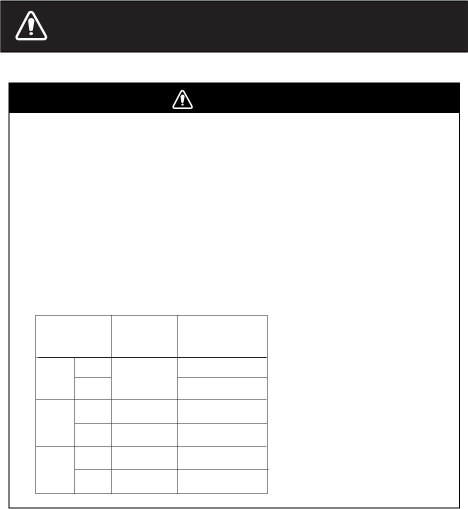
Radio Frequency Radiation Hazard
The radar antenna emits electromagnetic radio frequency (RF) energy which can be
harmful, particularly to your eyes. Never look directly into the antenna aperture from a
close distance while the radar is in operation or expose yourself to the transmitting
antenna at a close distance.
Distances at which RF radiation levels of 100 and 10 W/m2 exist are given in the table
below.
Note: If the antenna unit is installed at a close distance in front of the wheel house,
your administration may require halt of transmission within a certain sector of antenna
revolution. This is possible. Ask your FURUNO representative or dealer to provide
this feature.
MODEL Distance to
100 W/m2
point
Distance to
10 W/m2
point
FR-8062
Nil
Worst case
2.50 m
Worst case
2.30 m
XN-12A
XN-13A
XN-12A
XN-13A
Worst case
0.50 m
Worst case
0.30 m
Worst case
7.50 m
Worst case
7.00 m
FR-8122
XN-12A
XN-13A
Worst case
0.80 m
Worst case
0.70 m
Worst case
9.50 m
Worst case
9.00 m
FR-8252
ii
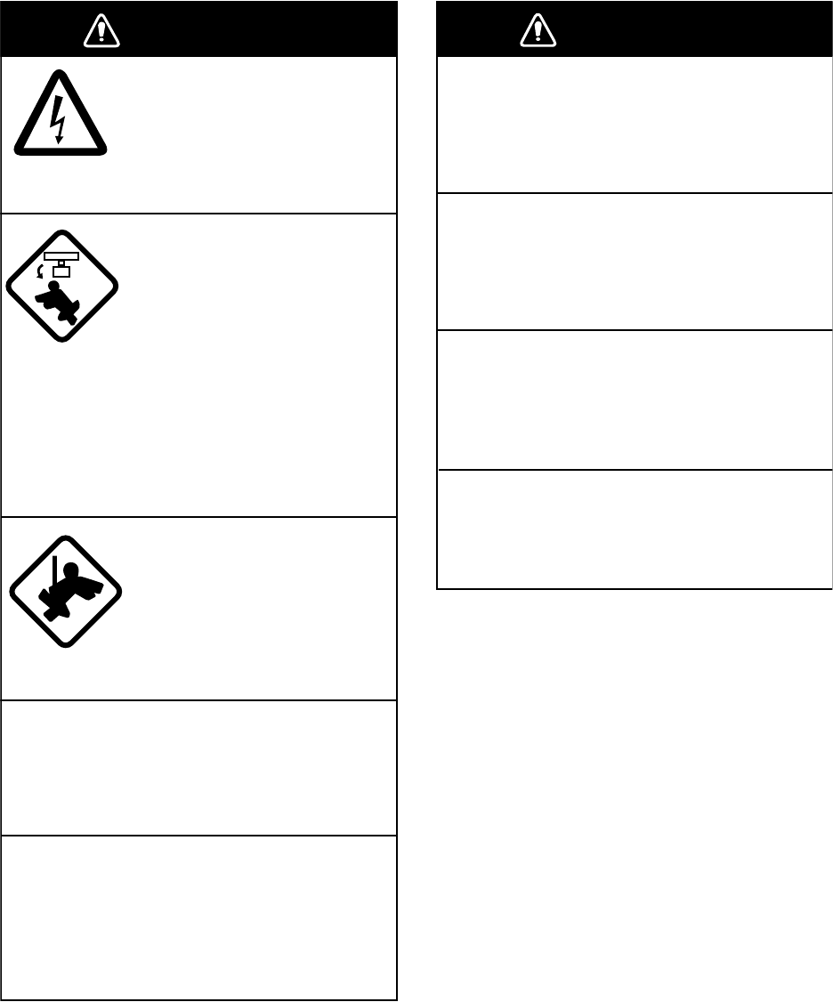
WARNING
ELECTRICAL SHOCK HAZARD
Do not open the equipment.
Only qualified personnel
should work inside the
equipment.
Turn off the radar power
switch before servicing the
antenna unit. Post a warn-
ing sign near the switch
indicating it should not be
turned on while the antenna
unit is being serviced.
Prevent the potential risk of
being struck by the rotating
antenna and exposure to
RF radiation hazard.
Wear a safety belt and hard
hat when working on the
antenna unit.
Serious injury or death can
result if someone falls from
the radar antenna mast.
Do not disassemble or modify the
equipment.
Fire, electrical shock or serious injury can
result.
Turn off the power immediately if water
leaks into the equipment or the equip-
ment is emitting smoke or fire.
Continued use of the equipment can cause
fire or electrical shock.
WARNING
Use the proper fuse.
Fuse rating is shown on the equipment.
Use of a wrong fuse can result in damage
to the equipment.
Keep heater away from equipment.
Heat can alter equipment shape and melt
the power cord, which can cause fire or
electrical shock.
Do not place liquid-filled containers on
the top of the equipment.
Fire or electrical shock can result if a liquid
spills into the equipment.
Do not operate the equipment with wet
hands.
Electrical shock can result.
iii
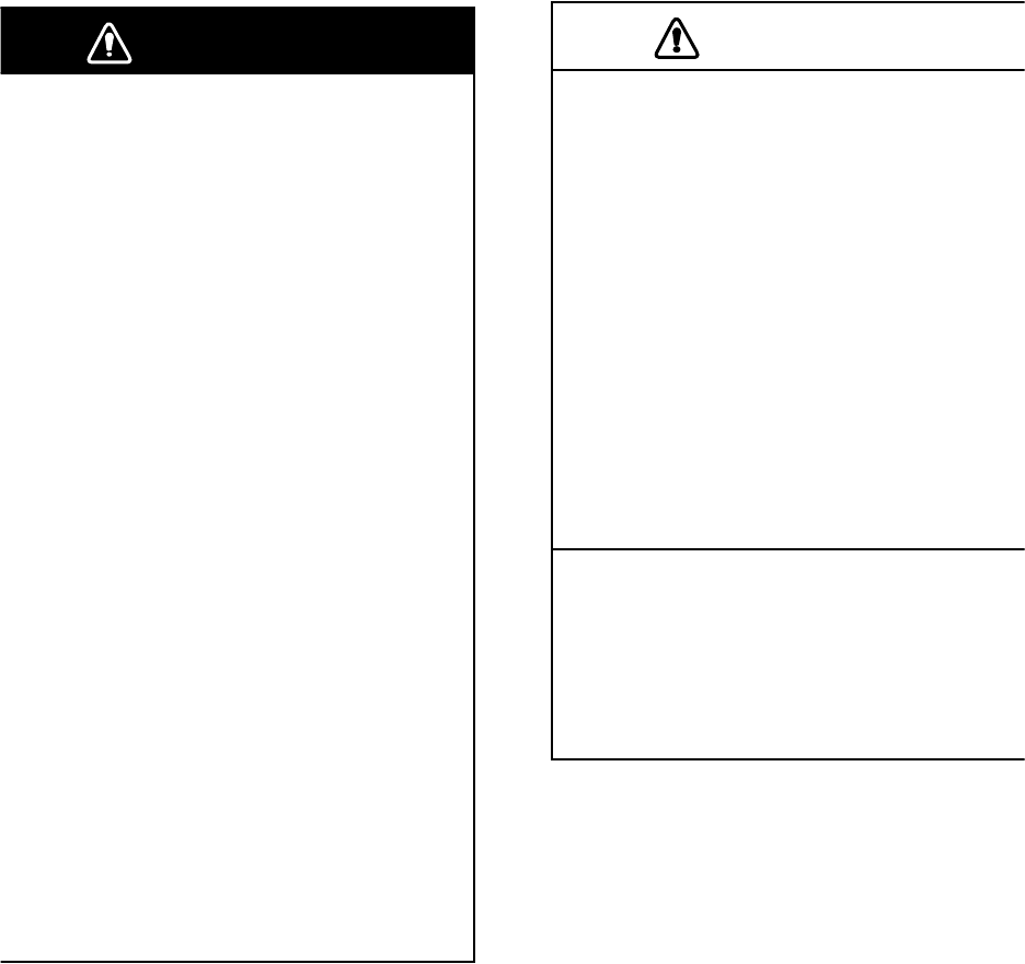
WARNING
WARNING
No one navigational aid should be relied
upon for the safety of vessel and crew.
The navigator has the responsibility to
check all aids available to confirm
position. Electronic aids are not
a substitute for basic navigational
principles and common sense.
• This ARP automatically tracks
automatically or manually acquired radar
targets and calculates their courses and
speeds, indicating them by vectors. Since
the data generated by the auto plotter
are based on what radar targets are
selected, the radar must always be
optimally tuned for use with the auto
plotter, to ensure required targets will not
be lost or unwanted targets such as sea
returns and noise will not be acquired
and tracked.
• A target does not always mean a land-
mass, reef, ships or other surface vessels
but can imply returns from sea surface
and clutter. As the level of clutter changes
with environment, the operator should
properly adjust the A/C SEA, A/C RAIN
and GAIN controls to be sure target
echoes are not eliminated from the
radar screen.
CAUTION
The plotting accuracy and response of
this ARP meets IMO standards.
Tracking accuracy is affected by the
following:
• Tracking accuracy is affected by course
change. One to two minutes is required t
o
restore vectors to full accuracy after an
abrupt course change. (The actual
amount depends on gyrocompass
specifications.)
• The amount of tracking delay is inversely
proportional to the relative speed of the
target. Delay is on the order of 15—30
seconds for high relative speed; 30—60
seconds for low relative speed.
The data generated by ARP, AIS and
video plotter are intended for
reference only.
Refer to official nautical charts for
detailed and up-to-date information.
iv
WARNING
To avoid electrical shock, do not
remove cover. No user-serviceable
parts inside.
WARNING LABEL
Warning labels are attached to the
equipment. Do not remove any label.
If a label is missing or damaged,
contact a FURUNO agent or dealer
about replacement.
WARNING
ARNING
Radiation hazard. Only qualified
personnel should work inside scanner.
Confirm that TX has stopped before
opening scanner.
DISPLAY UNIT
Name: Warning Label (1)
Type: 86-003-1011-0
Code No.: 100-236-230
ANTENNA UNIT
Name: Radiation Warning Label
Type: 03-142-3201-0
Code No.: 100-266-890
TFT LCD
The high quality TFT (Thin Film Transistor)
LCD displays 99.999% of its picture ele-
ments. The remaining 0.01% may drop out
or light, however this is an inherent property
of the LCD; it is not a sign of malfunction.

v
TABLE OF CONTENTS
FOREWORD...............................................................................................ix
SYSTEM CONFIGURATION ......................................................................xi
1. OPERATIONAL OVERVIEW..............................................................1-1
1.1 Controls .....................................................................................................................1-1
1.2 Turning the Radar On/Off, Transmitting ....................................................................1-4
1.3 Display Indications.....................................................................................................1-5
1.4 Display Brilliance, Panel Dimmer ..............................................................................1-6
1.5 Menu Overview..........................................................................................................1-6
1.6 Tuning........................................................................................................................1-7
1.7 Presentation Modes...................................................................................................1-8
1.8 Choosing a Range Scale.........................................................................................1-10
1.9 Choosing a Pulse Length ........................................................................................1-11
1.10 Adjusting the Sensitivity...........................................................................................1-11
1.11 Suppressing Sea Clutter..........................................................................................1-12
1.12 Suppressing Rain Clutter.........................................................................................1-13
1.13 Automatic Suppression of Sea and Rain Clutters ...................................................1-14
1.14 Cursor......................................................................................................................1-15
1.15 Interference Rejector...............................................................................................1-16
1.16 Measuring the Range to a Target............................................................................1-17
1.17 Measuring the Bearing to a Target..........................................................................1-19
1.18 Measuring the Range and Bearing Between Two Targets......................................1-20
1.19 Target Alarm............................................................................................................1-21
1.20 Off Centering the Display ........................................................................................1-24
1.21 Zoom .......................................................................................................................1-25
1.22 Echo Stretch............................................................................................................1-26
1.23 Echo Averaging .......................................................................................................1-27
1.24 Target Trails ............................................................................................................1-28
1.25 Parallel Index Lines .................................................................................................1-31
1.26 Outputting Target Position, Inscribing Origin Mark..................................................1-32
1.27 Temporarily Hiding the Heading Line, Heading Marker...........................................1-33
1.28 Custom Setup..........................................................................................................1-34
1.29 Programming Function Keys (F1 and F2 keys) .......................................................1-36
1.30 Noise Rejector.........................................................................................................1-36
1.31 Suppressing Second-trace Echoes .........................................................................1-37
1.32 Watchman ...............................................................................................................1-37
1.33 Color Schemes........................................................................................................1-38
1.34 Navigation Data.......................................................................................................1-39
1.35 Dynamic Range .......................................................................................................1-41
1.36 Characteristics Curve ..............................................................................................1-42
1.37 Antenna Speed........................................................................................................1-42
1.38 Waypoint Mark.........................................................................................................1-43
1.39 Alarm Message Display...........................................................................................1-44
1.40 Echo Area................................................................................................................1-45
1.41 Customizing (Initial Menu) .......................................................................................1-46
2. RADAR OBSERVATION ....................................................................2-1
2.1 General......................................................................................................................2-1
2.2 False Echoes.............................................................................................................2-3
2.3 SART (Search and Rescue Transponder).................................................................2-5
2.4 RACON......................................................................................................................2-6
vi
3. ARP OPERATION .............................................................................. 3-1
3.1 Usage Precautions....................................................................................................3-1
3.2 Controls for Use with ARP ........................................................................................3-2
3.3 ARP Display On/Off ..................................................................................................3-2
3.4 Acquiring and Tracking Targets ................................................................................3-3
3.5 Terminating Tracking of ARP Targets.......................................................................3-4
3.6 Vector Attributes........................................................................................................3-5
3.7 History Display (target past position) ........................................................................3-6
3.8 ARP Target Data.......................................................................................................3-7
3.9 CPA and TCPA Alarm...............................................................................................3-8
3.10 Proximity Alarm .........................................................................................................3-9
3.11 Lost Target ................................................................................................................3-9
3.12 Symbol Color...........................................................................................................3-10
4. AIS OPERATION................................................................................ 4-1
4.1 Controls for Use with AIS.........................................................................................4-1
4.2 Activating, Deactivating the AIS Function .................................................................4-1
4.3 Turning the AIS Display On or Off.............................................................................4-2
4.4 AIS Symbols..............................................................................................................4-2
4.5 Activating Targets .....................................................................................................4-2
4.6 Displaying AIS Target Data.......................................................................................4-3
4.7 Display Range...........................................................................................................4-4
4.8 Sorting Targets..........................................................................................................4-4
4.9 Display Sector...........................................................................................................4-5
4.10 Number of Targets to Display ...................................................................................4-5
4.11 Vector Attributes........................................................................................................4-6
4.12 History Display (target past position) ........................................................................4-7
4.13 CPA and TCPA Alarm...............................................................................................4-8
4.14 Proximity Alarm .........................................................................................................4-9
4.15 Lost Target ................................................................................................................4-9
4.16 Symbol Color...........................................................................................................4-10
5. GPS OPERATION .............................................................................. 5-1
5.1 Navigator Type..........................................................................................................5-1
5.2 Datum........................................................................................................................5-2
5.3 WAAS Setup .............................................................................................................5-2
5.4 Satellite Monitor ........................................................................................................5-3
5.5 Type 16 Message......................................................................................................5-4
5.6 GPS Sensor Installation Position Offset....................................................................5-5
5.7 Cold Start ..................................................................................................................5-6
6. MAINTENANCE & TROUBLESHOOTING ........................................ 6-1
6.1 Preventive Maintenance............................................................................................6-2
6.2 Replacement of Fuses ..............................................................................................6-3
6.3 Replacing the Magnetron..........................................................................................6-3
6.4 Trackball Maintenance ..............................................................................................6-4
6.5 SImple Troubleshooting ............................................................................................6-5
6.6 Advanced-level Troubleshooting...............................................................................6-6
6.7 System Test ..............................................................................................................6-8
6.8 LCD Test .................................................................................................................6-10
6.9 GPS Test.................................................................................................................6-11
6.10 Clearing the Memory............................................................................................... 6-12
SPECIFICATIONS................................................................................. SP-1
INDEX......................................................................................................IN-1

vii
FOREWORD
A Word to the Owner of the FR-8xx2 Marine Radar
FURUNO Electric Company thanks you for purchasing the FR-8xx2 Color LCD Marine Radar se-
ries. We are confident you will discover why the FURUNO name has become synonymous with
quality and reliability.
For over 50 years FURUNO Electric Company has enjoyed an enviable reputation for quality and
reliability throughout the world. This dedication to excellence is furthered by our extensive global
network of agents and dealers.
Your equipment is designed and constructed to meet the rigorous demands of the marine envi-
ronment. However, no machine can perform its intended function unless properly installed and
maintained. Please carefully read and follow the operation and maintenance procedures set forth
in this manual.
We would appreciate feedback from you, the end-user, about whether we are achieving our pur-
poses.
Thank you for considering and purchasing FURUNO.
Features
The FR-8xx2 series display radar targets on a bright 12.1" color LCD. Operation is simplified with
the combination of discrete keys and trackball.
The main features are as follows:
• The FR-8xx2 series consists of the following models:
• Bright 12.1" LCD visible even under direct sunlight
• User-friendly operation with combination of discrete keys, soft keys, and trackball
• Antenna speed may be automatically selected according to pulse length or speed
• Built in ARP optionally available
• AIS data shown with connection of AIS transponder
• User programmable function keys
• One touch setup of major controls with custom setup feature
• Echoes in yellow or green or colors of red, yellow or green in order of descending strength.
Model, output, max, range, antenna type
Model Output Range Radar Antenna
FR-8062 4.9 kW 72 nm/sm, 96 km 4 or 6 ft radiator
FR-8122 12 kW 72 nm/sm, 96 km 4 or 6 ft radiator
FR-8252 25 kW 96 nm/km/sm 4 or 6 ft radiator
viii
Notice
• No part of this manual may be copied or reproduced without written permission.
• This manual is lost or worn, contact your dealer about replacement.
• The contents of this manual and equipment specifications are subject to change without
notice.
• The example screens (or illustrations) shown in this manual may not match the screens you
see on your display. The screen you see depends on your system configuration and equip-
ment settings.
• This manual is intended for use by native speakers of English.
• FURUNO will assume no responsibility for the damage caused by improper use or modifica-
tion of the equipment or claims of loss of profit by a third party.
ix
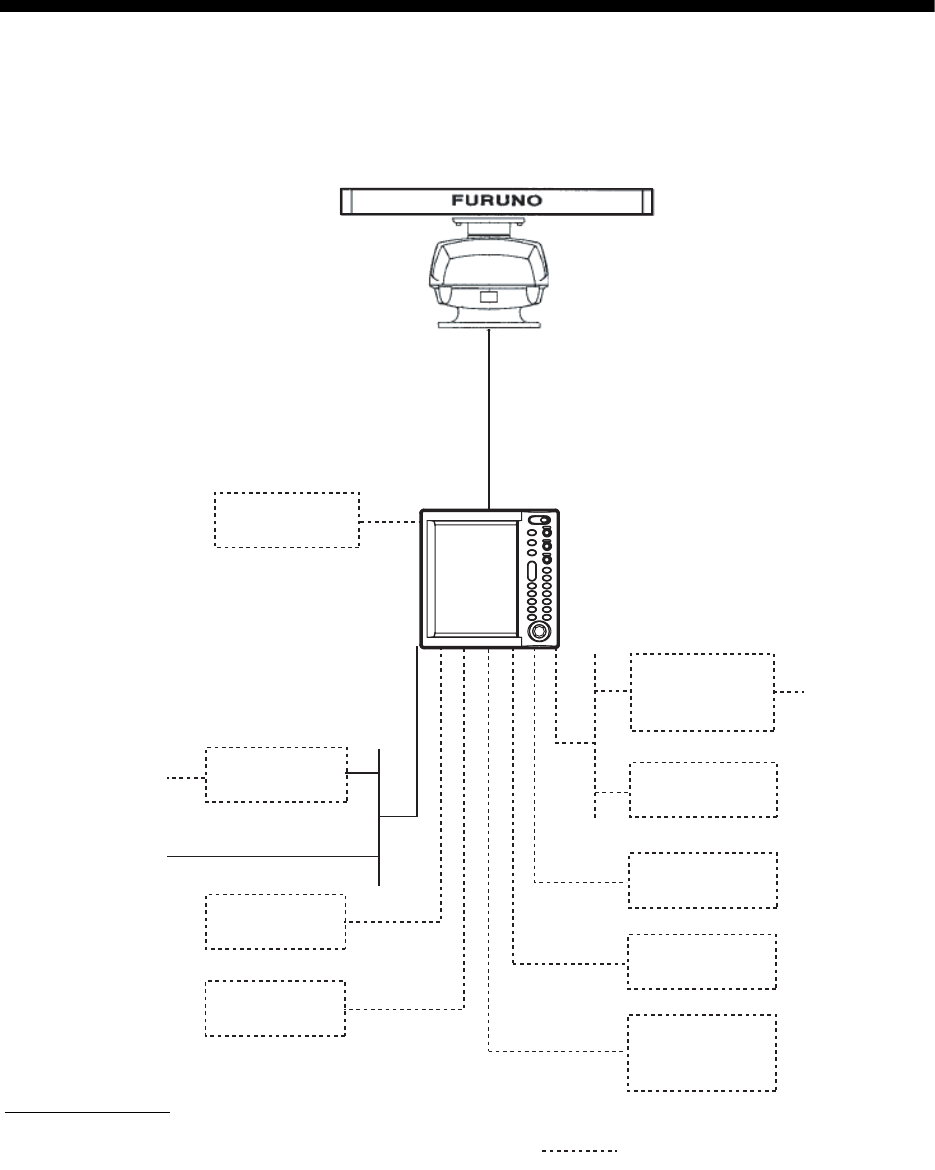
SYSTEM CONFIGURATION
FR-8062/8122
ANTENNA UNIT
RSB-0070-085-XN12A/XN13A: FR-8062
RSB-0073-085-XN12A/XN13A: FR-8062
RSB-0073-086-XN12A/XN13A: FR-8122
DISPLAY UNIT
RDP-150
Auto Plotter
ARP-11
(built in
display unit)
Rectifier
RU-3423
100/110/
115/220/
230 VAC, 1
φ
12-24 VDC
Remote
Display
SVGA
Monitor
Gyro
Converter
AD-100
Heading Sensor
PG-1000
NMEA
DEVICE
NMEA
DEVICE
External
Buzzer
OP03-136
: Optional equipment
Gyrocompass
Category of units
Antenna unit: Exposed to weather
All other units: Protected from weather
x
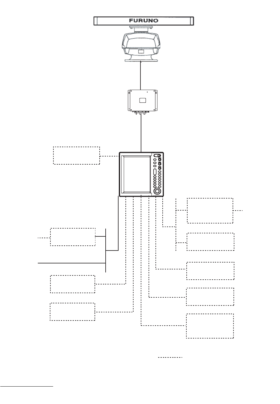
FR-8252
ANTENNA UNIT
RSB-0073-087-XN12A/XN13A
POWER SUPPLY UNIT
PSU-008
Auto Plotter
ARP-11
(built in
display unit)
Rectifier
RU-3423
12-24 VDC
Remote
Display
SVGA
Monitor
Gyro
Converter
AD-100
Heading Sensor
PG-1000
NMEA
DEVICE
NMEA
DEVICE
External
Buzzer
OP03-136
: Optional equipment
100/110/
115/220/
230 VAC, 1
φ
Gyrocompass
Category of units
Antenna unit: Exposed to weather
All other units: Protected from weather
DISPLAY UNIT
RDP-150
1-1
1. OPERATIONAL OVERVIEW
This chapter provides the information necessary for operating this radar.
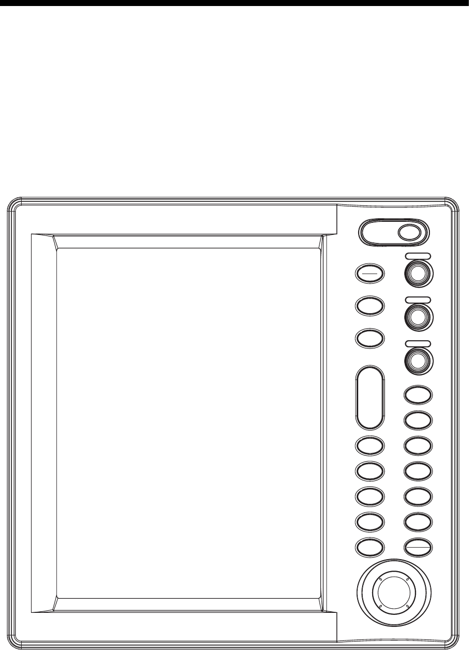
1.1 Controls
1.1.1 Display unit
This radar is operated with the controls of the display unit (and the remote controller). 17 keys are
labeled and they provide the function shown on their labels. The trackball's main function is to
move the cursor across the screen. When you correctly execute an operation, the unit generates
a beep. Invalid operation causes the unit to emit several beeps.
Display unit
ENTER
TARGET
ALARM
CANCEL
HL OFF
TLLMENU
EBL
ZOOM OFF
CENTER
TRAILS
VRM
F1
F2
PUSH AUTO/MAN
PUSH AUTO/MAN
PUSH AUTO/MAN
STBY
TX
MODE
CUSTOM
+
RANGE
-
POWER
BRILL
GAIN
SEA
RAIN

1. OPERATIONAL OVERVIEW
1-2
Control description
Control Description
POWER/BRILL Momentary press: Turns power on; adjusts brilliance.
Long press: Turns power off.
STBY/TX Ttransmits radar pulses and places radar in standby alternately.
MODE Chooses presentation mode.
CUSTOM Presets radar controls for one-touch setup of radar.
RANGE Chooses radar range.
ZOOM Zooms chosen target.
TARGET ALARM Sets target alarm, which watches for targets entering or exiting the user-
set alarm zone.
EBL Measures bearing to a radar target.
MENU Open/closes the menu.
ENTER Registers chosen menu option; acquires ARP target; displays data of
selected ARP or AIS target.
GAIN Adjusts the sensitivity of the radar receiver.
SEA Suppresses sea clutter.
RAIN Suppresses rain clutter.
F1, F2 Programmable function keys.
OFF CENTER Shifts own ship position.
TRAILS Plots radar echo movement.
VRM Measure range to a radar target.
TLL Outputs position of chosen target to navigation plotter or inscribes mark
at cursor location, or both.
CANCEL/HL OFF Cancels last entry in menu operation; temporarily erases heading line;
cancels tracking of ARP target; removes data of selected ARP or AIS
target from data box; goes back one “layer” in multi-layer menu.
Trackball Chooses menu items; shifts display and cursor.
1. OPERATIONAL OVERVIEW
1-3
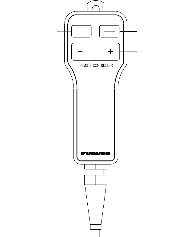
1.1.2 Remote controller
The remote controller provides armchair control over transmit, standby, rante and display offcen-
tering.
Remote controller
Chooses range.
OFF
CENTER STBY
TX
RANGE
Toggles STBY/TX
Offcenters display.
1. OPERATIONAL OVERVIEW
1-4
1.2 Turning the Radar On/Off, Transmitting
Press the POWER/BRILL key at the upper right-hand corner of the control panel to turn on the
radar on. Press and hold down the key until the screen turns black to turn the radar off.
At power-up the start-up screen appears as shown right. The model name and program number
are shown and the ROM and RAM are tested. If "NG" appears as the results of the ROM and RAM
tests, try pressing any key to proceed. If normal operation is not possible, contact your dealer for
advice. After the tests are completed, the bearing scale and a digital timer appear. The digital timer
counts down the time remaining to warm up the magnetron, which transmits the radar pulses. This
warm-up takes 90 sec. (FR-8252) or 180 sec. (FR-8062, FR-8122).
Start-up screen
After the timer has counted down to 0:00, the indication STBY appears at the screen center,
meaning the radar is now ready to transmit radar pulses. Press the STBY/TX key to transmit radar
pulses.
The STBY/TX key toggles between stand-by and transmit status. The antenna rotates in transmit
condition and is stopped in standby. Because the magnetron ages with use it is highly recom-
mended to set the radar in standby when it will not be required for an extended period of time. This
will help extend the life of the magnetron.
Quick start
Provided that the radar was once in use with the transmitter tube (magnetron) still warm, you can
get the radar into TRANSMIT condition without the warm-up. If the POWER/BRILL key was
turned off by mistake or the like and you wish to restart the radar promptly, turn on the POWER/
BRILL key not later than 10 seconds after power-off. This feature is not available with the FR-
8252.
12.1" Color LCD
Marine Radar
FR-8xx2
FURUNO ELECTRIC CO., LTD.
ROM: OK RAM: OK
Program No. 0317010-XX.XX
Model name appears here.
1. OPERATIONAL OVERVIEW
1-5
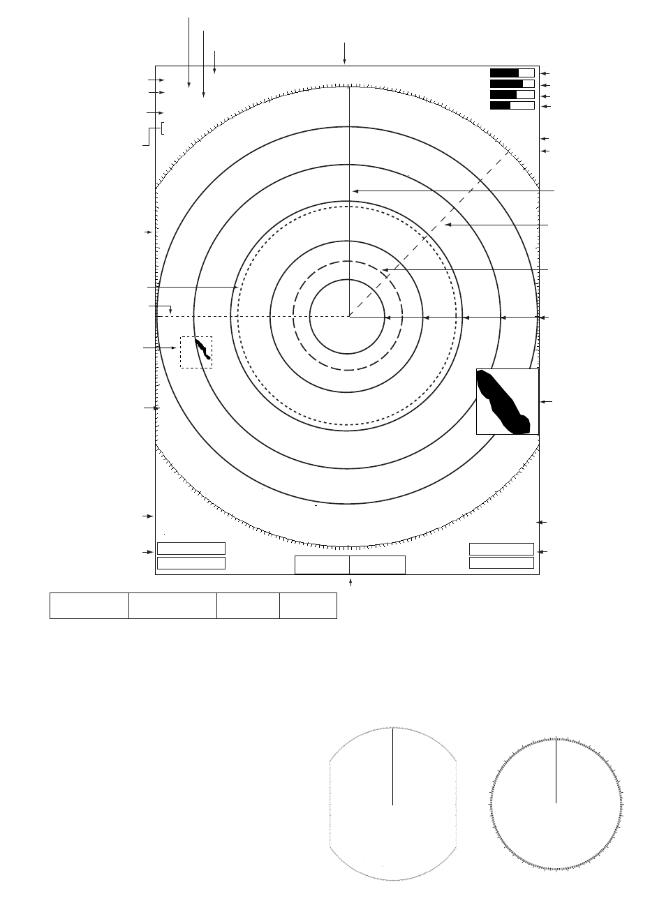
1.3 Display Indications
Display indications
Note: The screen configuration, chosen during
the installation, is available in three types,
“Sea”, “River” and “IEC”, and the default config-
uration is “Sea”. The majority of the descrip-
tions in this manual use the “Sea” configuration.
The major difference between the Sea, River
and IEC configurations is the bearing scale - it
is elliptical on the Sea and River types and cir-
cular on the IEC type.
EBL1
VRM1
Heading
Range ring
OWN LAT: 34
°
56.123 E
SHIP LON: 135
°
34.567 E
SPEED 12.34 kt
CURSOR LAT: 34
°
56.123 E
LON: 135
°
34.567 E
TTG: 01:00
TEMP 12.3
°
C
DEPTH 56.7 M
WAY 0.095 NM
POINT 90.0
°
M
TTG: 00:20
Nav data:
Appears at screen bottom when Data Box in the
Display sub menu is set to "Nav" or "All". Appropriate sensors
required to display nav data.
359.9°
M
+ 242.8°R 2.782 NM
Cursor data
(Range and bearing or L/L position)
+
VRM2
EBL2
Bearing scale
Heading line
Presentation mode
Range ring interval
Custom settings
Range
Pulse length
Echo stretch (ES),
Echo averaging (EAV)
Noise rejector (NR),
Interference rejector (IR)
3
NM
SP NUP
ES1 EAV1
NR LOW
IR LOW
HARBOR A/C AUTO
0.5
Zoom
TUNE AUTO
GAIN AUTO
SEA MED
RAIN LOW
TUNE indicator
GAIN indicator
SEA indicator
RAIN indicator
2ND ECHO
ZOOM
2nd echo rejector
ALARM1_IN
ALARM2_OUT
VRM2 0.742
NM
Alarm status
VRM1, VRM2
range
VRM1>1.430<
NM
<
TRAILS (T)
01H30M00S
EBL2 045.0°
R
Trail ref.,
Trail time
EBL1, EBL2
bearing
EBL1>270.0°
R
<
+
Cursor
+
Zoom cursor
Zoom
window
000 030
060
09
0
120
150
180
210
240
270
300
330
Bearing scale for Sea and
River configurations
Bearing scale for
IEC configuration
1. OPERATIONAL OVERVIEW
1-6
1.4 Display Brilliance, Panel Dimmer
The display brilliance and panel dimmer may be adjusted as follows:
1. Press the POWER/BRILL key momentarily to show the brilliance/panel dialog box.
Brilliance/panel dimmer dialog box
2. Roll the trackball upward or downward to choose Brill or Panel, whichever you wish to adjust.
3. Roll the trackball rightward or leftward to adjust. (You may also use the POWER/BRILL key.)
4. Press the MENU key to close the window.
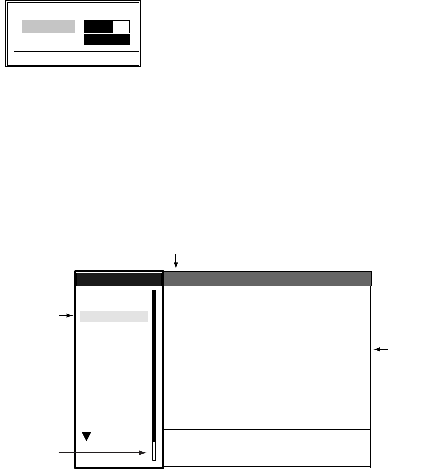
1.5 Menu Overview
Less-often used functions are controlled through the menu, which consists of 14 menus and 3 sub
menus. Use the trackball to choose item and option as below.
1. Press the MENU key to display the menu.
Menu
2. Roll the trackball to choose a menu or sub menu. As you roll the trackball, the highlight in the
Menu column indicates menu currently selected and the menu items change according to the
menu selected.
3. Press the ENTER key to enable operation from chosen menu.
W Min Max X
Brill (1 - 15) 9 9
Panel (1 - 7) 7
[ENTER]: Close
S
T
System
GPS
Brill/Color
Echo
Mark
Target Trails
Custom 1
Display
Custom 2
Custom 3
Target
ARP
AIS
Manual Tune
Auto Rain
Tune
Pulse Length
Auto Gain
Auto Sea
Echo Stretch
Echo Average
:Auto
:Short
:1
:Off
:Rough
:Calm
:Moderate
Auto Anti Clutter
Display-Dynamic
Display-Curve
Noise Rejector
Interference Rejector
2nd Echo Rejector
:Normal
:1
:Off
:
:Off
:Off
Menu
Menu
Echo
Echo
Menus
Menu item
s
and options
Currently selected menu
Menu location
indicator
S/T / W/X: Select
[ENTER]: Enter [CANCEL/HL OFF]: Back
[MENU]: Exit
1. OPERATIONAL OVERVIEW
1-7
4. Roll the trackball to choose the menu item desired and then press the ENTER key. A window
with options for the corresponding menu item appears. For example, the window below shows
the options for Trail Color in the Target Trails menu.
Target trails color options
5. Roll the trackball upward or downward to choose appropriate option.
6. Press the ENTER key to save your selection.
7. Press the MENU key to close the menu.
Note: The menus on the IEC-type radar close automatically when there is no menu operation for
10 seconds, as per IEC regulations. The following menus and screens however are exempt from
this rule: Alarm message, GPS self test, Satellite monitor, TYPE 16 message, Diagnostic, LCD
pattern, and Tune initial adjust. Menus do not close automatically in the “River” or “Sea” configu-
ration.
1.6 Tuning
The radar receiver can be tuned automatically or manually, and the default tuning method is auto-
matic. If you require manual tuning, do the following:
1. Use the RANGE key to choose the 48-mile range.
2. Press the MENU key to display the main menu.
3. Use the trackball to choose Echo and then press the ENTER key.
4. Use the trackball to choose Tune Mode and then press the ENTER key.
Tuning options
5. Choose Manual and then press the ENTER key.
6. Choose Manual Tune and then push the ENTER key. The window shown below appears.
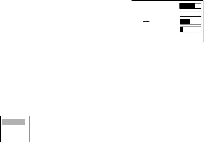
7. Roll the trackball upward or downward to adjust the tuning, watching the tuning bar at the top
right corner. he best tuning point is where the bar graph swings maximum. The vertical bar on
the bar graph shows tuning control position; not the tuning condition.
Tuning indicator
8. Push the ENTER key to finish.
9. Press the MENU key to close the menu.
Green
Red
Blue
White
Black
Auto
Manual
2048
(0-4095)
TUNE MANL
GAIN AUTO
SEA MANL
RAIN AUTO
Tuning method (Manual) Tuning bar

1. OPERATIONAL OVERVIEW
1-8
1.7 Presentation Modes
This radar has the following presentation modes:
Relative Motion (RM)
Head-up: Unstabilized
Head-up TB: Head-up with compass-stabilized bearing scale (True Bearing) where bearing scale
rotates with the compass reading.
Course-up: Compass-stabilized relative to ship's orientation at the time of electing course-up.
North-up: Compass-stabilized with reference to north
True Motion (TM)
North-up: Ground or sea stabilized with compass and speed inputs
1.7.1 Choosing presentation mode
Press the MODE key consecutively to choose presentation mode desired. The presentation mode
in use appears at the top left corner on the screen.
NOTICE - Loss of gyrocompass signal: When the compass signal is lost, "HEADING" appears
in red at the gyro readout, the presentation mode automatically becomes head-up, all ARP and
AIS targets and map or chart are erased. After restoring the compass signal, choose the presen-
tation mode with the MODE key.
1.7.2 Description of presentation modes
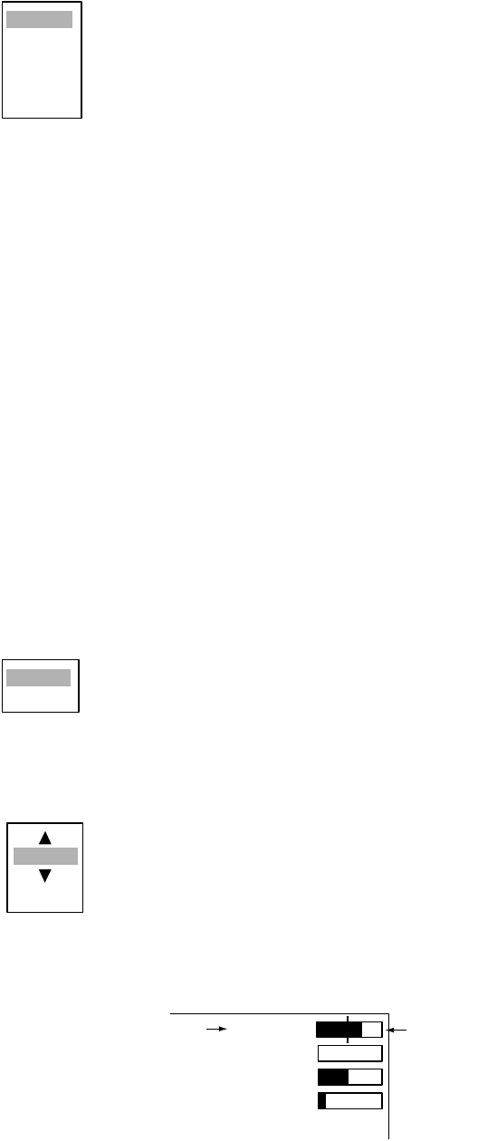
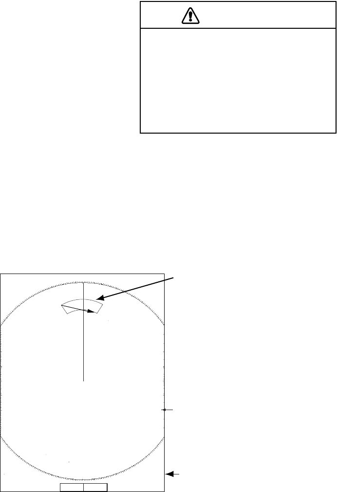
Head-up mode
The head-up mode is a display in which the line connecting own ship and the top of the display
indicates own ship's heading.
The target pips are painted at their measured distances
and in their directions relative to own ship's heading.
A short line on the bearing scale is the north marker indi-
cating heading sensor north. A failure of the heading
sensor input will cause the north marker to disappear
and the readout to show ***.* and the message SIGNAL
MISSING appears in red at the lower-right corner of the
screen.
Heading Lin
e
N
orth Marker
1. OPERATIONAL OVERVIEW
1-9
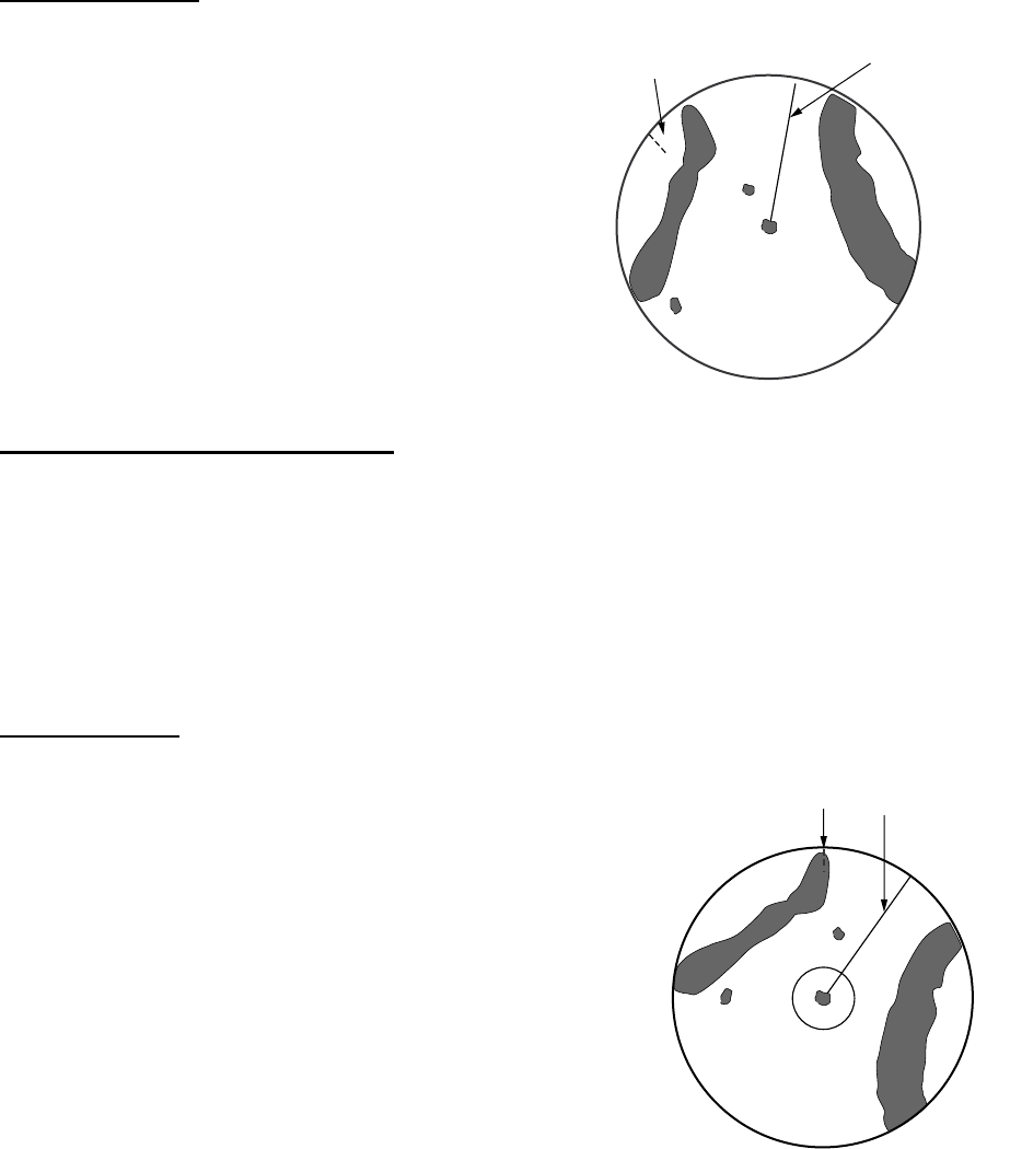
Course-up mode
The course-up mode is an azimuth stabilized dis-
play in which a line connecting the center with the
top of the display indicates own ship's intended
course (namely, own ship's previous heading just
before this mode has been selected).
Target pips are painted at their measured dis-
tances and in their directions relative to the
intended course, which is maintained at the 0-
degree position. The heading line moves in accor-
dance with ship's yawing and course change. This
mode is useful to avoid smearing of picture during
course change.
Head-up TB (True Bearing) mode
Radar echoes are shown in the same way as in the head-up mode. The difference from normal
head-up presentation lies in the orientation of the bearing scale. The bearing scale is heading
sensor stabilized. That is, it rotates in accordance with the heading sensor signal, enabling you to
know own ship's heading at a glance.
This mode is available when the radar is interfaced with a gyro heading sensor.
If the gyro heading sensor fails, the bearing scale returns to the state of head-up mode.
North-up mode
The north-up mode paints target pips at their measured dis-
tances and in their true (heading sensor) directions from own
ship, north bearing maintained at the top of the screen. The
heading line changes its direction according to the ship's
heading. Requires heading signal.
If the compass fails, the presentation mode changes to head-
up and the north marker disappears. Also, the HDG indication
shows ***.*. And the message “SIGNAL MISSING HEADING”
appears in red at the lower-right corner of the screen.
Heading Line
North Marker
Heading Line
North Marker
1. OPERATIONAL OVERVIEW
1-10
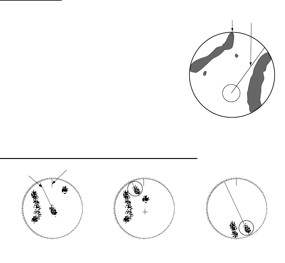
True motion mode
Own ship and other moving objects move in accordance with
their true courses and speed. In ground stabilized TM, all
fixed targets, such as landmasses, appear as stationary
echoes. In the sea stabilized TM without set and drift inputs,
the landmass can move on the screen. Note that true motion
is not available on the 72 nm or 96 nm range scale.
When own ship reaches a point corresponding to 50% of the
radius of the display, own ship position is automatically reset
to a point of 75% radius opposite to the extension of the
heading line passing through the display center. You may
also reset the own ship symbol manually by pressing the
OFFCENTER key.
If the heading sensor fails, the mode is changed to the head-
up and the north marker disappears. The HDG readout shows ***.* and the message “SIGNAL
MISSING HEADING” appears.
Automatic resetting of own ship mark in true motion mode
1.8 Choosing a Range Scale
The selected range scale, range ring interval and pulse length are shown at the upper left corner
on the screen. When a target of interest comes closer, reduce the range scale so that it appears
in 50-90% of the display radius.
Use the RANGE key to choose range desired. Hit the "+" part of the key to raise the range; the "-
" part to lower the range.
Heading Line
North Marker
000 010 020 030
040
050
060
070
080
090
100
110
120
130
140
150
160
170180190
200
210
220
230
240
250
260
270
280
290
300
310
320
330 340 350 000 010 020 030
040
050
060
070
080
090
100
110
120
130
140
150
160
170180190
200
210
220
230
240
250
260
270
280
290
300
310
320
330 340 350
Heading
line
North
marker 000 010 020 030
040
050
060
070
080
090
100
110
120
130
140
150
160
170180190
200
210
220
230
240
250
260
270
280
290
300
310
320
330 340 350
(a) True motion
is selected (b) Own ship has reached a
point 75% of display radius (c) Own ship is automatically
reset to 75% of radius
1. OPERATIONAL OVERVIEW
1-11
1.9 Choosing a Pulse Length
The pulse length in use appears at the top left position on the screen. Appropriate pulse lengths
are preset to individual range scales and functions keys. If you are not satisfied with the pulse
length setting on the 1.5 nm or 3 nm range, you may change it as below.
1. Press the MENU key to open the menu.
2. Use the trackball to choose the Echo menu and then press the ENTER key.
3. Use the trackball to choose Pulse Length and then press the ENTER key.
4. Choose Short or Long as appropriate and then press the ENTER key.
5. Press the MENU key to close the menu.
1.10 Adjusting the Gain (sensitivity)
The GAIN control adjusts the sensitivity of the receiver. The proper setting is such that the back-
ground noise is just visible on the screen. If you set up for too little sensitivity, weak echoes may
be missed. On the other hand excessive sensitivity yields too much background noise; strong tar-
gets may be missed because of the poor contrast between desired echoes and the background
noise on the display.
1.10.1 Choosing gain adjustment method
Gain may be adjusted automatically or manually. Push the GAIN control to choose automatic or
manual adjustment alternately. The adjustment method currently chosen is show at the top right
corner of the screen. In the example below the adjustment method is “AUTO”.
Gain adjustment method indicator
1.10.2 Automatic gain adjustment
1. Press the MENU key to open the menu.
2. Choose the Echo menumenu and then press the ENTER key.
3. Choose Auto Gain and then press the ENTER key.
4. Choose the sea condition which best matches the auto gain options.
5. Press the ENTER key followed by the MENU key to close the menu.
Short
Long
TUNE MANL
GAIN AUTO
SEA MANL
RAIN AUTO
Gain adjustment method (AUTO)
Rough
Moderate
Calm
1. OPERATIONAL OVERVIEW
1-12
1.10.3 Manual gain adjustment
1. Push the GAIN control to show “GAIN MANL” as the gain adjustment method.
2. Rotate the GAIN control to adjust the gain. Adjust the control so background noise is just visible
on the screen.
1.11 Suppressing Sea Clutter
Echoes from waves cover the central part of the display with random signals known as sea clutter.
The higher the waves, and the higher the antenna above the water, the further the clutter will
extend. When sea clutter masks the picture, use the SEA control to suppress the clutter, either
manually or automatically.
1.11.1 Choosing sea clutter adjustment method
Sea clutter may be adjusted automatically or manually. Push the SEA control to choose automatic
or manual adjustment alternately. The adjustment method currently chosen is show at the top right
corner of the screen. In the example below the sea clutter adjustment method is “MANL”
(manual).”
SEA indicator
1.11.2 Automatic sea clutter adjustment
1. Press the MENU key to open the menu.
2. Choose the Echo menu and then press the ENTER key.
3. Choose Auto Sea and then press the ENTER key.
4. Choose the sea condition which best matches the Auto Sea options.
5. Press the ENTER key followed by the MENU key to close the menu.
TUNE MANL
GAIN AUTO
SEA MANL
RAIN AUTO
SEA adjustment method (MANUAL)
Rough
Moderate
Calm
1. OPERATIONAL OVERVIEW
1-13
1.11.3 Manual sea clutter adjustment
1. Push the SEA control to show “SEA MANL” as the SEA adjustment method.
2. Rotate the SEA control to suppress sea clutter.
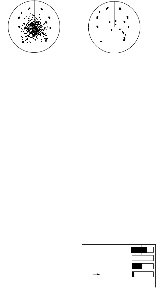
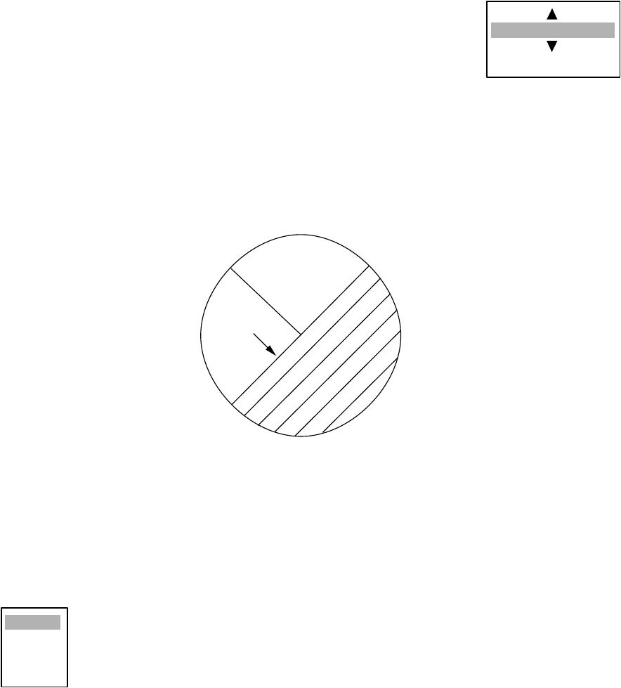
The proper setting of the SEA control should be such that the clutter is broken up into small dots,
and small targets become distinguishable. If the setting is set too low, targets will be hidden in the
clutter, while if the setting is too high, both sea clutter and targets will disappear from the display.
In most cases adjust the control until clutter has disappeared to leeward, but a little is still visible
windward.
How to adjust the SEA control
1.12 Suppressing Rain Clutter
The vertical beamwidth of the scanner is designed to see surface targets even when the ship is
rolling. However, by this design the unit will also detect rain clutter (rain, snow, or hail) in the same
manner as normal targets.
The RAIN control adjusts the receiver sensitivity as the SEA control does but rather in a longer
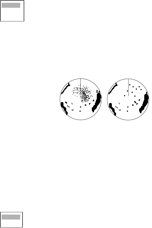
time period (longer range). The higher the setting the greater the anti-clutter effect. When echoes
from precipitation mask solid targets, adjust the control to split up these unwanted echoes into a
speckled pattern, making recognition of solid targets easier.
1.12.1 Choosing rain clutter adjustment method
Rain clutter may be adjusted automatically or manually. Push the RAIN control to choose auto-
matic or manual adjustment alternately. The adjustment method currently chosen is show at the
top right corner of the screen. In the example below the adjustment method is “AUTO.”
RAIN indicator
SEA adjusted;
sea clutter suppressed
Sea clutter at
screen center
TUNE MANL
GAIN AUTO
SEA MANL
RAIN AUTO
RAIN adjustment method (AUTO)
1. OPERATIONAL OVERVIEW
1-14
1.12.2 Automatic rain clutter adjustment
1. Press the MENU key to open the menu.
2. Choose the Echo menu and then press the ENTER key.
3. Choose Auto Rain and then press the ENTER key.
4. Choose the sea condition which best matches the Auto Rain options.
5. Press the ENTER key followed by the MENU key to close the menu.
1.12.3 Manual rain clutter adjustment
1. Push the A/C RAIN control to show “RAIN MANL” as the RAIN adjustment method.
2. Rotate the A/C RAIN control to suppress the rain clutter.
How to adjust the A/C RAIN control
1.13 Automatic Suppression of Sea and Rain Clutters
Both sea and rain clutters may be adjusted automatically. When this feature is active it overrides
the SEA and RAIN controls.
1. Press the MENU key to open the menu.
2. Choose the Echo menu and then press the ENTER key.
3. Choose Auto Anti Clutter and then press the ENTER key.
4. Choose Off or On as appropriate.
5. Press the ENTER key followed by the MENU key to close the menu.
Rough
Moderate
Calm
Rain clutter at RAIN control adjusted
screen center
Off
On
1. OPERATIONAL OVERVIEW
1-15
1.14 Cursor
The cursor functions to fthe range and bearing to a target or latititude and longitude position of a
target, and the default function is range and bearing. Roll the trackball to position the cursor and
then read cursor data at the screen bottom.
Cursor data
1.14.1 Cursor data
Cursor data can be shown as latitude and longitude or range and bearing to the cursor.
1. Press the MENU key to open the menu.
2. Choose the Mark menu and then press the ENTER key.
3. Choose Brg/Rng or Lat/Long as appropriate.
4. Press the ENTER key followed by the MENU key to close the menu.
Cursor data
(L/L or range and bearing)
+ 110.1°R 2.525 NM
+
3
NM
0.5
Curs
or
+
1. OPERATIONAL OVERVIEW
1-16
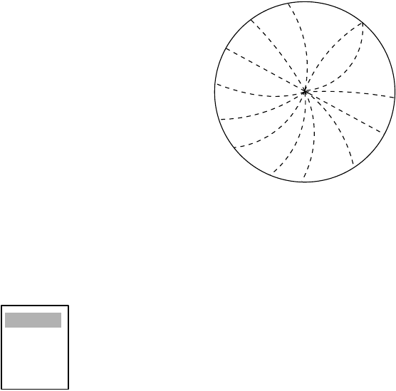
1.15 Interference Rejector
Mutual radar interference may occur in the vicinity of another shipborne radar operating in the
same frequency band. It is seen on the screen as a number of bright spikes either in irregular pat-
terns or in the form of usually curved spoke-like dotted lines extending from the center to the edge
of the picture. Activating the interference rejector circuit can reduce this type of interference.
The interference rejector is a kind of signal correlation circuit. It compares the received signals
over successive transmissions and suppresses randomly occurring signals. There are three levels
of interference rejection depending on the number of transmissions that are correlated.
Interference
1. Press the MENU key to open the menu.
2. Choose the Echo menu and then press the ENTER key.
3. Choose Interference Rejector and then press the ENTER key.
4. Choose Off, Low, Med or High as appropriate and then press the ENTER key.
5. Press the MENU key to close the menu.
Be sure to turn off the interference rejector when no interference exists so as not to miss small
targets.
Off
Low
Med
High
1. OPERATIONAL OVERVIEW
1-17
1.16 Measuring the Range to a Target
The range to a target may be measured three ways: with the fixed range rings, with the cursor (if
set to measure range and bearing), or with the VRM.
Use the fixed range rings to obtain a rough estimate of the range to a target. They are the concen-
tric solid circles about own ship, or the sweep origin. The number of rings is automatically deter-
mined by the selected range scale and their interval is displayed at the upper-left position of the
screen. Count the number of rings between the center of the display and the target. Check the
range ring interval and judge the distance of the echo from the inner edge of the nearest ring.
1.16.1 Adjusting range ring brilliance
1. Press the MENU key to open the menu.
2. Choose the Brill/Color menu and then press the ENTER key.
3. Choose Range Rings Brill and then press the ENTER key.
4. Choose appropriate brilliance and then press the ENTER key.
5. Press the MENU key to close the menu.
1.16.2 Measuring range by the variable range marker (VRM)
There are two VRMs, No. 1 and No. 2, which appear as dashed rings so that you can discriminate
them from the fixed range rings. The two VRMs can be distinguished from each other by different
lengths of dashes.
1. Press the VRM key to display either
of the VRMs. Successively pressing
the VRM key toggles the active
VRM between No. 1 and No. 2. The
currently active marker is enclosed
with >.....<.
2. Operate the Trackball to align the
active variable range marker with
the inner edge of the target of
interest and read its distance at the
lower-right corner of the screen.
Each VRM remains at the same
geographical distance when you
operate the RANGE key. This
means that the apparent radius of
the VRM ring changes in proportion
to the selected range scale.
3. Press the VRM key to erase each
VRM.
Off
Low
Medium
High
VRM1
+ 96.8°R 0.338 NM
VRM2 0.140
NM
VRM1, VRM2
range
VRM1>0.007
NM
<
+
VRM2
Target
How to measure range with VRMs
1. OPERATIONAL OVERVIEW
1-18
1.16.3 Choosing VRM unit
The unit of measurement used by the VRM can be selected to nautical miles, kilometers, statute
miles or kilometers/yard.
1. Press the MENU key to open the menu.
2. Choose the Mark menu and then press the ENTER key.
3. Choose VRM Unit and then press the ENTER key.
4. Choose desired unit and then press the ENTER key.
5. Press the MENU key to close the menu.
1.17 Measuring the Bearing to a Target
Use the Electronic Bearing Lines (EBLs) to take bearings of targets. There are two EBLs, No. 1
and No. 2. Each EBL is a straight dashed line extending out from the own ship position up to the
circumference of the radar picture. The fine dashed line is the No. 1 EBL and the coarse dashed
one is the No. 2 EBL.
1. Press the EBL key to display either of the EBLs. Successively pressing the EBL key toggles
the active EBL between No. 1 and No. 2. The currently active marker is enclosed with >.....<.
2. Operate the Trackball to bisect the target of interest with the EBL and read its distance at the
lower-left corner of the screen.
3. Press the EBL key to erase each EBL.
How to measure the bearing to a target with the EBL
nm
km
sm
kyd
EBL1
EBL1, EBL2
bearing
EBL1>270.0°R<
+
EBL2
EBL2 0.45.0°R
+ 96.8°R 0.338 NM
1. OPERATIONAL OVERVIEW
1-19
1.17.1 EBL reference
The EBL readout is affixed by "R." (relative) if it is relative to own ship's heading, "T." (true) if it is
referenced to the north. You may choose relative or true in the head-up modes; in all other modes
it is always TRUE.
1. Press the MENU key to open the menu.
2. Choose the Mark menu and then press the ENTER key.
3. Choose EBL Reference and then press the ENTER key.
4. Choose Relative or True as appropriate and then press the ENTER key.
5. Press the MENU key to close the menu.
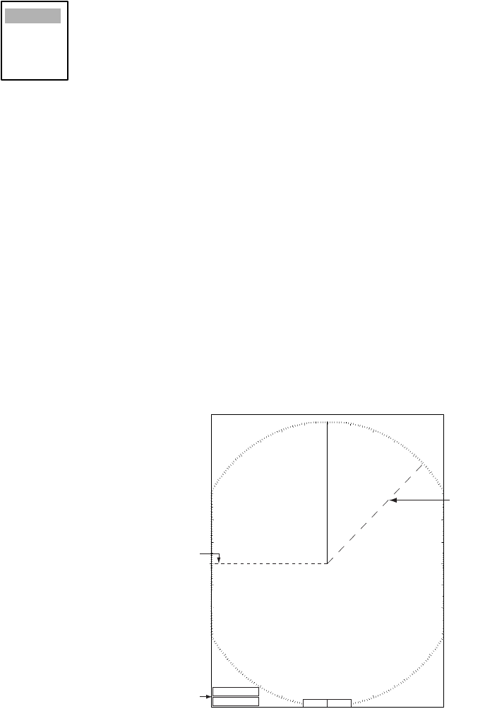
1.18 Measuring the Range and Bearing Between Two
Targets
You may shift the origin of the EBL to measure the range and bearing between two targets.
1. Press the EBL key to circumscribe the bearing indication of EBL1 or EBL2 with a dashed
rectangle.
2. Drag the EBL to the location of one target and then press the ENTER key to anchor the EBL.
3. Roll the trackball to shift the range marker to the location of the other target.
4. Read the bearing and range indications at the bottom of the screen.
Measuring range and bearing between two target with the EBL
To return the origin of the EBL to the screen center, press the EBL key to circumscribe the indi-
cation of that the EBL with a solid rectangle.
Relative
True
R2
N
o. 1
E
BL
No. 2
EBL
Range
Marker
Range/bearing
between targets 3 and
4
EBL1
EBL2
>140.0
°
R<
335.2
°
R
VRM1
VRM2
>0.500NM<
0.980NM
Range
Marker
Target 4
Target 3
Target 1
EBL
origin
++
Target 2
Range/bearing
between targets 1 and 2
1. OPERATIONAL OVERVIEW
1-20
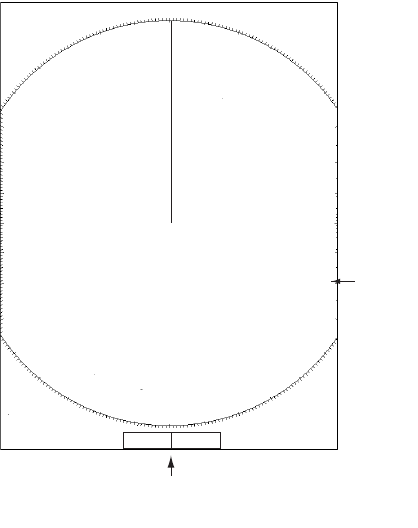
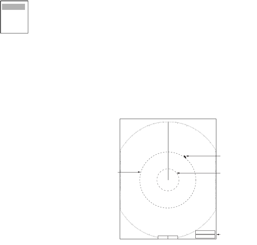
1.19 Target Alarm
The target alarm serves to alert the navigator to
targets (ships, landmasses, etc.) entering a set
area, with audible and visual alarms.
The guard alarm zone has a fixed width of 0.5 nm
in the radial direction (depth) and is adjustable from
3.0 to 6.0 nm (guard zone 1) and any distance
(guard zone 2). The sector of the zone can be set
from 0 to 360 degrees in any direction.
The alarm may be set to sound against targets
entering or exiting the zone. See paragraph 1.20.3.
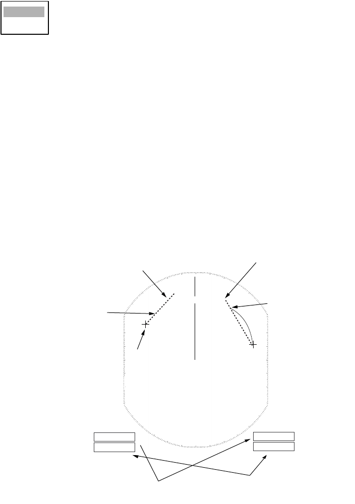
1.19.1 Setting a target alarm
The procedure which follows shows you how to set a target alarm, using the illustration below as
an example.
1. Press the TARGET ALARM key to activate ALARM 1 or ALARM 2 as appropriate.
2. Drag the cursor with the trackball to the location “A” and then press the ENTER key.
3. Drag the cursor to the location “B” and then press the ENTER key.
How to set a target alarm zone
Note 1: If you wish to create a target alarm zone having a 360-degree coverage around own ship,
set point "B" in almost the same direction as point "A."
Note 2: Two target alarm zones may be set. Note however that the 2nd target alarm zone is avail-
able only when the 1st target alarm zone is active.
Note 3: When the target alarm zone is not within the range in use the indication OUT RNG
appears in the alarm status area. In this case choose a range which will display the target alarm
zone.
CAUTION
• The alarm should not be relied upon as
the sole means for detecting possible
collision situations.
• SEA, RAIN and GAIN controls
should be properly adjusted to be sure
the alarm system does not overlook
target echoes.
+ 110.1°R 2.525 NM
+
3
NM
0.5
Cursor
+
+
Target alarm
zone
AB
ALARM1_IN
Alarm statu
s
1. OPERATIONAL OVERVIEW
1-21
1.19.2 Acknowledging the alarm
A target in the target alarm zone produces both visual (flashing) and audible (beep) alarms. To
silence the audible alarm, press the CANCEL/HL OFF key. The alarm status shows "ALARM1(or
2) ACK." This will deactivate the audible alarm but will not stop the flashing of the offending target.
To reactivate the audible alarm, press the CANCEL/HL OFF key The alarm status is then shown
as ALARM 1 (or 2) IN(or OUT).
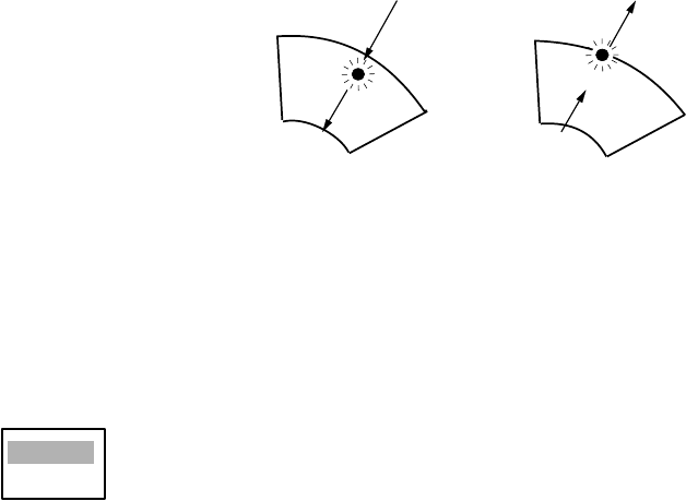
1.19.3 Choosing alarm type
As noted earlier the target alarm may be set sound against targets entering or exiting the alarm.
Choose desired type as below.
In and Out alarms
1. Press the MENU key to shown the menu.
2. Choose the Mark menu and then press the ENTER key.
3. Choose Target Alarm1 Mode or Target Alarm2 Mode as appropriate and then press the ENTER
key.
4. Choose In to get the alarm on targets entering target alarm zone or Out to get the alarm on
targets exiting a target alarm zone.
5. Press the ENTER key followed by the MENU key.
1.19.4 Deactivating a target alarm
1. Press the TARGET ALARM key to choose ALARM1 or ALARM2 indication at the bottom right
corner on the screen. The selected indication is circumscribed with a rectangle.
2. Press the CANCEL/HL OFF key.
3. Press the TARGET ALARM key again, and a dashed rectangle circumscribes the alarm indi-
cation selected.
4. Press the CANCEL/HL OFF key again. The target alarm zone and the alarm indication are
erased from the screen.
Inward target alarm Outward target alarm
In
Out
1. OPERATIONAL OVERVIEW
1-22
1.19.5 Choosing target strength which triggers target alarm
You may choose the target strength level which triggers the alarm as follows:
1. Press the MENU key to open the menu.
2. Choose the Initial sub menu from the System menu and the press the ENTER key.
3. Choose Alarm Level and then press the ENTER key.
4. Choose the echo strength level which you want to trigger the target alarm.
5. Press the ENTER key.
6. Press the MENU key to close the menu.
1.20 Off Centering the Display
Own ship position, or sweep origin, can be displaced to expand the view field without switching to
a larger range scale. The sweep origin can be off-centered to the cursor position, but not more
than 75% of the range in use; if the cursor is set beyond 75% of the range scale, the sweep origin
will be off-centered to the point of 75% of the limit.
This feature is not available on the 72 nm or 96 nm range scale nor in the true motion mode.
The display may be off centered manually, or automatically according to ship’s speed. Press the
OFF CENTER key successively to choose desired off centering method or turn off centering, in
the sequence of manual, automatic, off. OFF CENTER appears at the top left corner on the dis-
play when off centering is enabled. Off center is not available when the zoom function is in use.
1.20.1 Automatic off center
The amount of automatic shift is calculated according to ship's speed, and the amount of shift is
limited to 50% of the range in use. For example, if you set the shift speed setting for 15 knots and
the ship is running at 10 knots the amount of shift will be about 34%. The formula for determining
shift amount is as shown below. Automatic shift mode is only available in the head-up mode.
Choosing speed to use
1. Press the MENU key to open the menu.
2. Choose the Initial sub menu from the System menu and press the ENTER key.
3. Choose Max Shift Speed and then press the ENTER key.
4. Choose the speed to use and then press the ENTER key.
5. Press the MENU key to close the menu.
Low
Medium
High
Ship's speed
Shift speed setting
X 0.5 = Amount of shift(%)
15
(1-99)
1. OPERATIONAL OVERVIEW
1-23
Activating automatic off center
Press the OFF CENTER key until OFF CENTER appears on the display and the display is not
shifted to the cursor location.
1.20.2 Manual off center
1. Place the cursor where you want locate the screen center.
2. Press the OFF CENTER key until the display shifts to cursor location.
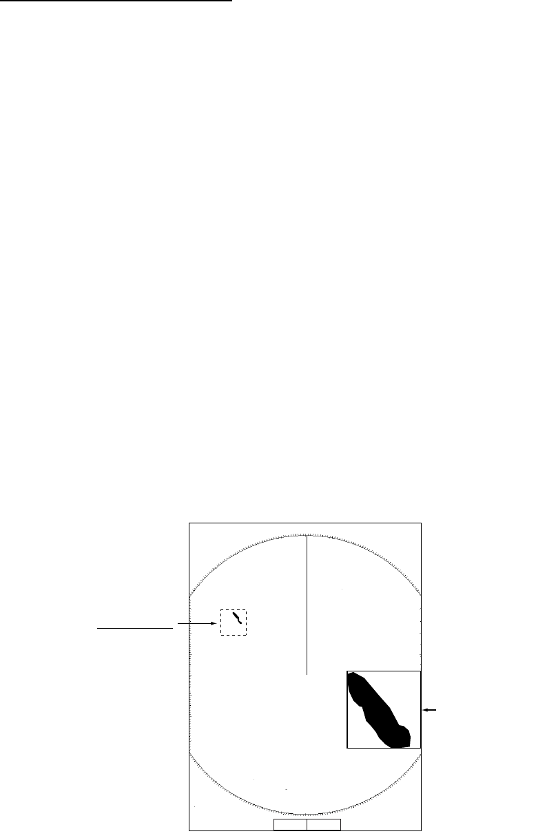
1.21 Zoom
The zoom function enlarges an area of interest as large as twice the normal viewing size, in the
zoom window. You choose the target of interest to zoom with the zoom cursor and that target is
zoomed in the zoom window. Zoom is not available when the display is off centered.
Three types of zoom are available: Relative, True and Target.
Relative: The zoom cursor moves relative to own ship’s heading.
True: The zoom cursor moves with course and speed of own ship.
Target: The zoom cursor is fixed to the zoomed target.
1.21.1 How to zoom
1. Press the ZOOM key to turn on the zoom feature. ZOOM appears at the top right hand corner
of the screen together with the zoom cursor, a square (dashed or solid, depending on zoom
mode chosen) with a cursor at its center, and the zoom window. The location of the zoom win-
dow depends on the location of the zoom cursor. If the zoom cursor is on the left-half of the
screen, the zoom window is located at the right side of the screen and vice versa.
Zoom
2. For the Relative and True modes you may fix the zoom cursor, by pressing the ZOOM key
again. the zoom cursor then becomes solid.
3. To quit zoom, press the ZOOM key again.
+ 180.1°R 2.121 NM
+
3
NM
0.5
+
+
Z
oom cursor
(
dashed in
r
elative or true
m
ode)
Zoom
window
1. OPERATIONAL OVERVIEW
1-24
1.21.2 Zoom mode
You may choose the zoom mode from among Relative, True or Target.
1. Press the MENU key to open the menu.
2. Choose the Mark menu and press the ENTER key.
3. Choose Zoom and then press the ENTER key.
4. Choose the appropriate echo stretch option and then press the ENTER key.
5. Press the MENU key to close the menu.
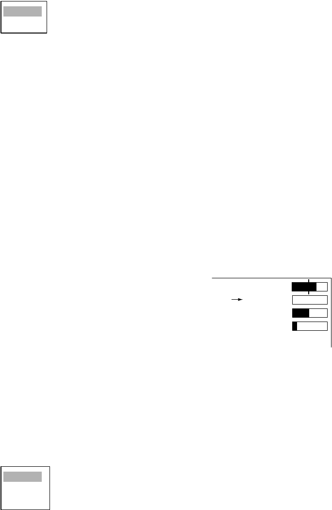
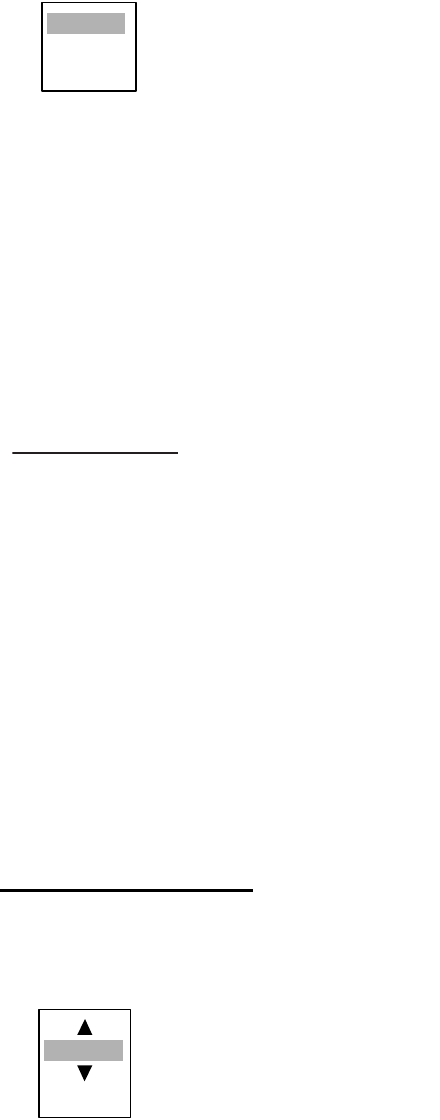
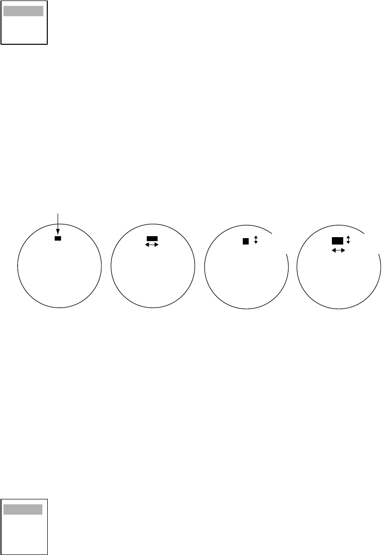
1.22 Echo Stretch
The echo stretch feature enlarges targets to make them easier to see, and it is available on the
1.5 -12 nm ranges depending on echo stretch type. There are 3 settings: ES1 to enlarge in bearing
direction for long range detection, ES2 to enlarge in range direction and ES3 to enlarge in bearing
and range directions.
Echo stretch
Note 1: If the 1.5 nm is preset with a pulse length of S1 or S2, and the 3 nm scale with S2, the
echo stretch is not available on those range scales.
Note 2: The echo stretch magnifies not only small target pips but also returns (clutter) from sea
surface, rain and radar interference. For this reason, make sure these types of interference have
been sufficiently suppressed before activating the echo stretch.
1. Press the MENU key to open the menu
2. Choose the Echo menu and press the ENTER key.
3. Choose Echo Stretch and then press the ENTER key.
4. Choose the appropriate echo stretch option and then press the ENTER key.
5. Press the MENU key to close the menu.
Relative
True
Target
Echo Stretch 1 Echo Stretch 2 Echo Stretch 3
Bearing
direction
Range
direction
Echo Stretch OFF
Target
Bearing
direction
Range
direction
Use on range
1.5 - 12 nm Use on range
1.5 - 6 nm
Off
1
2
3

1. OPERATIONAL OVERVIEW
1-25
1.23 Echo Averaging
The echo average feature effectively suppresses sea clutter. Echoes received from stable targets
such as ships appear on the screen at almost the same position every rotation of the antenna. On
the other hand, unstable echoes such as sea clutter appear at random positions.
To distinguish real target echoes from sea clutter, echoes are averaged over successive picture
frames. If an echo is solid and stable, it is presented in its normal intensity. Sea clutter is averaged
over successive scans resulting in reduced brilliance, making it easier to discriminate real targets
from sea clutter.
Echo averaging uses scan-to-scan signal correlation technique based on the true motion over the
ground of each target. Thus, small stationary targets such as buoys will be shown while sup-
pressing random echoes such as sea clutter. True echo average is not however effective for
picking up small targets running at high speeds over the ground.
Note 1: Do not use the echo average function under heavy pitching and rolling; loss of target
detection can result.
Note 2: Echo average can be used without a heading sensor. For further details, contact your
dealer.
To properly use the echo average function, it is recommended to first suppress sea clutter with
the A/C SEA control. Then, do as follows:
1. Press the MENU key to open the menu.
2. Choose the Echo menu and press the ENTER key.
3. Choose Echo Stretch and then press the ENTER key.
4. Choose the appropriate echo stretch option and then press the ENTER key.
5. Press the MENU key to close the menu.
Off
1
2
3
1. OPERATIONAL OVERVIEW
1-26
1.24 Target Trails
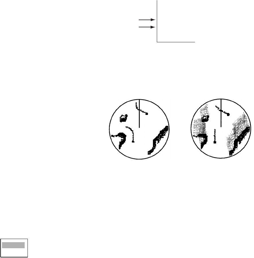
The trails of the radar echoes of targets may be displayed in the form of synthetic afterglow. Target
trails are chosen either relative or true and may be sea or ground stabilized. True motion trails
require a compass signal and own ship speed input.
1.24.1 Starting, stopping trails
Press the TRAILS key to start trails and choose trail time. The chosen time, along with trail mode,
is shown at the bottom left corner as shown in the figure below.
Trail time is available among 15 s, 30 s, 1 min., 3 min., 6 min., 15 min., 30 min., Long trail setting
(if activated, see paragraph 1.24.10) and CONT(INUOUS) The longer the trail interval the longer
the length of the target trail.
Trail indications
To cancel all trails, press the TRAILS key to erase the trail indications.
1.24.2 Trail mode
You may display echo trails in true or rel-
ative motion (only true trail on TM). Rel-
ative trails show relative movements
between targets and own ship. True
motion trails require a gyrocompass
signal and own ship speed input to
cancel out own ship's movement and
present true target movements in accor-
dance with their over-the-ground speeds
and courses.
True
and relative target trails
1. Press the MENU key to open the menu.
2. Choose the Target Trails menu and press the ENTER key.
3. Choose Mode and then press the ENTER key.
4. Choose the appropriate mode and then press the ENTER key.
5. Press the MENU key to close the menu.
TRAILS (T)
01H30M00S
Trail Mode (T, True, R, Relative)
Trail Time
(a) True target trails
(No smearing of
stationary targets)
(b) Relative target trails
Targets moving relative
to own ship
Relative
True
1. OPERATIONAL OVERVIEW
1-27
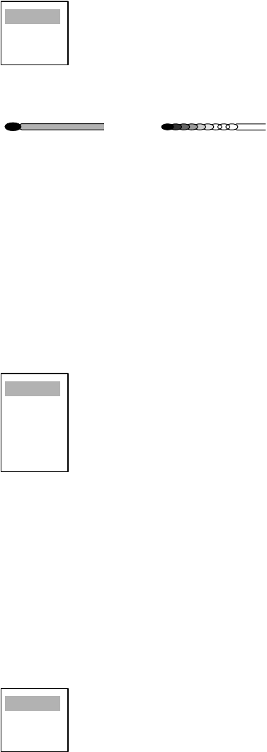
1.24.3 Trail gradation
Trails may be shown in single or multiple gradation (monocolor) or in multicolor.
1. Press the MENU key to open the menu.
2. Choose the Target Trails menu and press the ENTER key.
3. Choose Trail Gradation and then press the ENTER key.
4. Choose the appropriate trail gradation referring to the figure below and then press the ENTER
key. The item Rainbow display trails in multicolor.
5. Press the MENU key to close the menu.
1.24.4 Trail color
You may choose trail color as follows:
1. Press the MENU key to open the menu.
2. Choose the Target Trails menu and press the ENTER key.
3. Choose Color and then press the ENTER key.
4. Choose the appropriate color and then press the ENTER key.
5. Press the MENU key to close the menu.
1.24.5 Trail level
The level (intensity) of the afterglow which extends from radar targets may be chosen as below.
1. Press the MENU key to open the menu.
2. Choose the Target Trails menu and press the ENTER key.
3. Choose Color and then press the ENTER key.
4. Choose 1, 2 or 3 as appropriate level and then press the ENTER key.
1: All: signals produce trails, 2: Normal, 3: Only weak signals produce trails
5. Press the MENU key to close the menu.
Single
Multiple
Rainbow
Monotone
(Single) Gradual shading
(Multi)
Green
Red
Blue
White
Black
1
2
3
1. OPERATIONAL OVERVIEW
1-28
1.24.6 Trail copy
Trails are canceled and restarted whenever the range is changed. However, you may continue
trails on the same range, without restarting them, when the range is changed to a next larger or
smaller range scale. Note however that when the range is changed, only those trails within the
previous range are continued; no trails are generated for targets outside the previous range.
How trail copy works
1. Press the MENU key to open the menu.
2. Choose the Target Trails menu and press the ENTER key.
3. Choose Trail Copy and then press the ENTER key.
4. Choose Off or On as appropriate and then press the ENTER key.
5. Press the MENU key to close the menu.
1.24.7 Thin trails
Target trails may be painted with thinner lines if desired. This can be useful when there are a lot
of targets on the screen.
1. Press the MENU key to open the menu.
2. Choose the Target Trails menu and press the ENTER key.
3. Choose Thin and then press the ENTER key.
4. Choose Off or On as appropriate and then press the ENTER key.
5. Press the MENU key to close the menu.
1.24.8 Own ship trail
You may show own ship’s trail as follows:
1. Press the MENU key to open the menu.
2. Choose Own Ship and then press the ENTER key.
3. Choose Off or On as appropriate and then press the ENTER key.
4. Press the MENU key to close the menu.
(a) Previous range (b) New range
No trail generated
for target not within
previous range
Off
On
1. OPERATIONAL OVERVIEW
1-29
1.24.9 Restarting trails
You may clear all target trails to restart the trail process. Target trails are cleared and the trailing
process restarts from time count zero at the current target trail plot interval.
1. Press the MENU key to open the menu.
2. Choose Restart Trails and then press the ENTER key.
3. Choose Off or On as appropriate and then press the ENTER key.
4. Press the MENU key to close the menu.
1.24.10 Long trails
Several preset trail times are provided for your convenience. If you prefer a different time you may
set it as below. The setting range is 45 minutes to 48 hours, in increments of 15 minutes.
1. Press the MENU key to open the menu.
2. Choose Long Trails and then press the ENTER key.
3. Roll the trackball upward or downward as appropriate to set time and
then press the ENTER key.
4. Press the MENU key to close the menu.
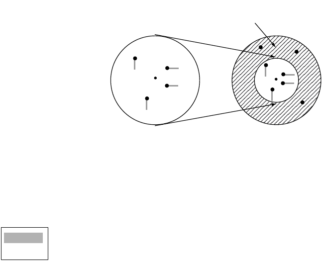
1.25 Parallel Index Lines
Parallel index lines are useful for keeping a constant distance between own ship and a coastline
or a partner ship when navigating. Two index lines are available and any two may be displayed.
You may control the orientation and line interval.
Parallel index lines
1.25.1 Turning parallel index lines on or off
1. Press the MENU key to show the menu.
2. Choose Mark and then press the ENTER key.
3. Choose Parallel Line and then press the ENTER key.
00h:00m
(00h:45m-48h:00m)
Index
lines
Off
2
3
6

1. OPERATIONAL OVERVIEW
1-30
4. Choose the number of parallel index lines to show (2, 3 or 6) or choose Off to turn off the lines.
(The actual number of lines visible may be less depending on line interval.)
5. Press the ENTER key.
6. Press the MENU key to close the menu.
1.25.2 Using the parallel index lines
1. Press the EBL key to activate EBL2.
2. Roll the trackball to adjust the orientation of the lines.
3. Press the VRM key to activate VRM2.
4. Roll the trackball to adjust the interval between lines.
1.25.3 Parallel index lines mode
Index lines orientation may be chosen from parallel or vertical as follows:
1. Press the MENU key to open the menu.
2. Choose Mark and press the ENTER key.
3. Choose Parallel Line Mode and then press the ENTER key.
4. Choose Parallel or Vertical as appropriate and then press the ENTER key.
5. Press the MENU key to close the menu.
1.26 Outputting Target Position, Inscribing Origin
Mark
The TLL key functions to output cursor position to a navigation plotter (where it is marked on its
screen) and inscribe an asterisk (*) mark at cursor position. Twenty marks may be inscribed on
the screen. When you enter a 21st mark the eldest mark is erased to make room for the latest. To
erase a mark, place the cursor on it and press the CANCEL/HL OFF key.
1.26.1 TLL key mode
The TLL key can be preset to output target position, inscribe the origin mark or do both.
1. Press the MENU key to open the menu.
2. Choose Mark and press the ENTER key.
3. Choose TLL Key Mode and then press the ENTER key.
4. Choose TLL Output, Origin Mark or Both as appropriate and then press the ENTER key.
5. Press the MENU key to close the menu.
Parallel
Vertical
TLL Output
Origin Mark
Both

1. OPERATIONAL OVERVIEW
1-31
1.26.2 Origin mark mode
You may choose origin mark movement from either True or Relative as follows:
1. Press the MENU key to open the menu.
2. Choose Mark and press the ENTER key.
3. Choose Origin Mark Mode and then press the ENTER key.
4. Choose Relative or True as appropriate and then press the ENTER key.
5. Press the MENU key to close the menu.
1.27 Temporarily Hiding the Heading Line, Heading
Marker
The heading line indicate the ship's heading in all presentation modes. The heading line is a line
from the own ship position to the outer edge of the radar display area and appears at zero degrees
on the bearing scale in head-up mode; it changes the orientation depending on the ship orientation
in north-up and true motion modes. The heading marker is a small circle on the bearing scale to
indicate the heading when the display is off-centered or is in north-up or TM mode.
To temporarily hide the heading line and heading marker to look at targets existing dead ahead of
own ship, press and hold down the CANCEL/HL OFF key. To re-display the heading line release
the key.
Relative
True

1. OPERATIONAL OVERVIEW
1-32
1.28 Custom Setup
1.28.1 About custom setup
Every time your navigating environment or task changes, you must adjust the radar, which can be
a nuisance in a busy situation. Instead of changing radar settings case by case, it is possible to
assign the function keys to provide optimum settings for often encountered situations.
The radar's internal computer offers three default custom setups (see the table below). However
you may customize theses settings to meet your navigation needs, on the Custom 1, Custom 2
and Custom 3 menus.
To enable a custom setup, press the CUSTOM key. Each press of the key enables CUSTOM1,
CUSTOM or CUSTOM3 cyclically. The chosen custom setup name is shown at the top left corner.
To escape from custom setup, operate any control.
Default custom settings
Menu item
(radar function)
Default settings
Custom1 Custom2 Custom3
Name Harbor Long Sea
Gain Moderate Moderate Moderate
Sea Calm Calm Calm
Rain Calm Calm Calm
Pulse length Short Long Short
Echo stretch Off 2 Off
Echo average Off 3 3
Noise rejector Off Med High
Interference rejector High Low High
Auto anti-clutter Off Off Off
Display dynamic Wide Normal Wide
Display-curve 1 3 3
Antenna speed 48 rpm 24 rpm 48 rpm

1. OPERATIONAL OVERVIEW
1-33
1.28.2 Description of custom setup items
Description of custom setup items
1.28.3 Setting custom setups
1. Press the MENU key to show the menu.
2. Choose Custom 1, Custom 2 or Custom 3 as appropriate and then press the ENTER key.
3. Choose Name and then press the ENTER key to display the options shown right.
4. Choose the name which best matches your desired objective and then press the
ENTER key.
5. Set other menu items according to the objective name chosen at step 4.
6. After adjusting all menu items, choose Save and then press the ENTER key.
CUSTOM SAVE COMPLETE appears when saving is completed.
7. Press the MENU key to close the menu.
Menu item Description of available settings See paragraph;
Name Harbor: Optimum setting for short range navigation in a
harbor area using a range scale of 1.5 nm or less
Long: Optimum setting for long range detection using a
range scale of 6 nm or larger
Sea: Optimum setting for navigating in heavy seas.
Rain: Optimum setting for navigating in heavy rain.
Buoy: Optimum setting for detecting navigation buoys.
Bird: Optimum setting for detecting birds.
Gain Rough, Moderate, Calm: Choose according to sea state.
Manual: Manual adjustment
1.11
Sea Rough, Moderate, Calm: Choose according to sea state.
Manual: Manual adjustment
1.12
Rain Rough, Moderate, Calm: Choose according to sea state.
Manual: Manual adjustment
1.13
Pulse length Short or Long, changeable on 1.5 and 3 nm ranges. 1.10
Echo stretch Off, 1, 2, 3 1.23
Echo average Off, 1, 2, 3 1.24
Noise rejector Off, Low, Med, High 1.30
Interference rejector Off, Low, Med, High 1.16
Auto anti-clutter Off, On 1.14
Display dynamic Narrow, Normal, Wide. 1.36
Display-curve 1, 2, 3 1.37
Antenna speed 24 rpm, 36 rpm, 48 rpm, Auto/Range. 1.38
Harbor
Long
Sea
Rain
Buoy
Bird

1. OPERATIONAL OVERVIEW
1-34
1.29 Programming Function Keys (F1 and F2 keys)
Less-often used functions are provided in the menu. To avoid opening the menus to set up the
radar for a particular situation, you may program a function key to provide one-touch access to a
desired function.
Function key operation
To activate a function, simply press the appropriate function key. Then, that function’s options
appear. Push the function key again to choose appropriate option and then press the ENTER key.
The default programs are F1, Echo averaging, F2, Display color.
Changing function key program
To change function key program, do the following:
1. Press the MENU key to show the menu.
2. Choose Display and then press the ENTER key.
3. Choose Function 1 Setup or Function 2 Setup as appropriate and then press the ENTER key.
Function list
4. Choose desired function from the list and then press the ENTER key.
5. Press the MENU key to close the menu.
1.30 Noise Rejector
White noise may show itself on the screen as random "speckles" spread over the entire radar
image. You can remove this noise as follows:
1. Press the MENU key to show the menu.
2. Choose Echo and then press the ENTER key.
3. Choose Noise Rejector and then press the ENTER key.
4. Choose On or Off as appropriate and then press the ENTER key.
5. Press the MENU key to close the menu.
Range Rings Brill
Echo Color
Display Color
Background Color
Echo Color
Watchman Time
Data Box
Zoom Mode
STBY Mode Display
Auto Gain
Auto Sea
Auto Rain
Tune Mode
Pulse Length
Echo Stretch
Echo Average
Noise Rejector
Interference Rejector
Auto Anti Clutter
Display-Dynamic
Display-Curve
Antenna Speed
2nd Echo Rejector
Trails-Gradation
Trails-Color
Trails-Mode
Trails-Level
Trails-Copy
Trails-Restart
Trails-Thin
Trails-Own Ship
Waypoint Mark Display
Origin Mark Mode
TLL Key Mode
Parallel Line
Parallel Line Mode
EBL Reference
VRM Unit
Cursor Position
Target Alarm1 Mode
Target Alarm 2 Mode
Vector Time
Vector Reference
History Dots
History Intervals
CPA
TCPA
Proximity Alarm
ARP-Display
ARP-Symbol Color
ARP-Auto Acquire
ARP-All Cancel
AIS-Display
AIS-Symbol Color
AIS-Sort By
GPS-Type
GPS-Datum
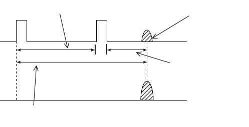
1. OPERATIONAL OVERVIEW
1-35
1.31 Suppressing Second-trace Echoes
In certain situations, echoes from very distance targets may appear as false echoes (second-trace
echoes) on the screen. This occurs when the return echo is received one transmission cycle later,
or after a next radar pulse has been transmitted.
How 2nd trace echoes are produced
1. Press the MENU key to show the menu.
2. Choose Echo and then press the ENTER key.
3. Choose 2nd Echo Rejector and then press the ENTER key.
4. Choose On or Off as appropriate and then press the ENTER key.
5. Press the MENU key to close the menu.
1.32 Watchman
The watch alarm sounds the audible alarm at the chosen time interval to help you keep regular
watch of the radar picture for safety or other purposes.
The watchman time appears at the lower-left corner of the screen with a watch alarm timer which
counts down from value set (for example, "10:00").
When a preset time interval has elapsed, the audible watch alarm is released, the screen label
WATCH turns red and the watch alarm timer freezes at "0:00." To silence the alarm, press the
CANCEL/HL OFF key The label WATCH turns to normal color and the watch alarm timer is reset
to the initial value and starts the count-down sequence again.
If you press the CANCEL key before the selected time interval is reached, the watch alarm timer
is reset to the initial value and starts the count-down sequence again.
To set watch time interval, do the following:
1. Press the MENU key to show the menu.
2. Choose DIsplay and then press the ENTER key.
3. Choose Watchman Time and then press the ENTER key.
4. Choose Off or appropriate time and then press the ENTER key.
5. Press the MENU key to close the menu.
Second-trace
echo
Tx repetition
Actual range
False echo
range
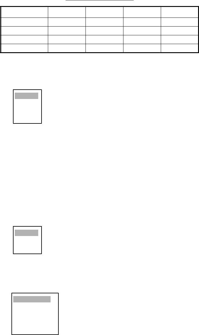
1. OPERATIONAL OVERVIEW
1-36
1.33 Color Schemes
1.33.1 Preset color schemes
Preset color schemes are provided for optimum viewing in daytime, nighttime and twilight. A user
arrangeable color scheme is also provided. Below are the default color settings for each preset
color scheme.
1. Press the MENU key to show the menu.
2. Choose Brill/Color and then press the ENTER key.
3. Choose Display Color and then press the ENTER key.
4. Choose a color scheme and then press the ENTER key.
5. Press the MENU key to close the menu.
1.33.2 User color scheme
The user color scheme lets you choose desired echo color and background color. The display
color must be set for “User” (in paragraph 1.33.1) to use user chosen echo and background colors.
1. Press the MENU key to show the menu.
2. Choose Brill/Color and then press the ENTER key.
3. Choose Echo Color and then press the ENTER key.
4. Choose a color and then press the ENTER key. Multi displays echoes in colors of red, yellow
and green according to echo strength, and it is not available on the IMO spec. radar.
5. Choose Background Color and then press the ENTER key.
6. Choose background color desired and then press the ENTER key.
7. Press the MENU key to close the menu.
Display item and color
Day Night Twilight User
Text Black Red Green Green
Range rings Green Red Green Green
Echo Yellow Green Green Green
Background White Black Blue Black
Day
Night
Twilight
User
Yellow
Green
Multi
Black/Green
Black/Red
Blue/White
DK Blue/White
White/Green
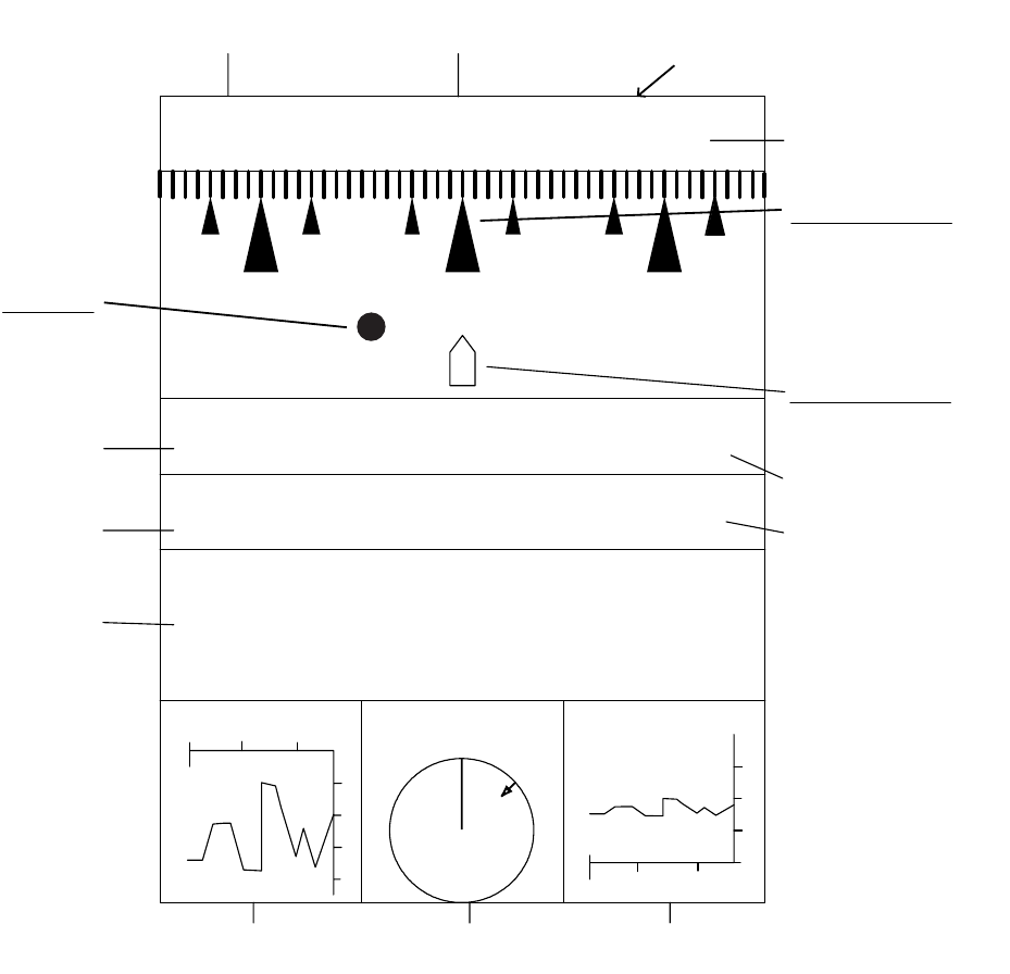
1. OPERATIONAL OVERVIEW
1-37
1.34 Navigation Data
1.34.1 Navigation data during standby
Navigation data is shown when the radar is in standby. Appropriate sensors required to display
data.
Navigation data display at standby
14/MAY/2004
DATE
SPEED COURSE
POSITION
NNNE NE ENNWNW W
HEADING
LAT
LONG
90° 00.000 N
180° 00.000 E
99.9
kts
359.9°
TIME
23 : 59 : 59
XTE
9.99nm 359.9° STBY
20
40
80
60
DEPTH (m)
30
30
20
0
10
TEMP 65.3 65.3
20 10
20 10
WIND 65.3 (m/s)
45.0° (R)
N
Time until Tx in watchman
(Displayed when watchman is active.)
<WATCH> 19:59
(min)
30(min)
Heading indicator
Graphic appears even
if bearing signal is los
t,
however the compass
point indications do n
ot
appear.
Standby indicationi
Own ship marker
Fixed regardless
of ship's movement.
Heading
XTE-track
error
W
aypoint
F
lashes if
v
essel goes
o
utside display
b
earing.
Speed
Date
Position
Depth Wind speed
and direction Water
teemperature
Course
Time
(°C)

1. OPERATIONAL OVERVIEW
1-38
Depth and water temperature graphs
These graphs display the latest 30 minutes of respective data. The horizontal axis scale is
updated and plotted at intervals of 10 seconds. The vertical axis scale is adjusted automatically
for every 30 minutes of data. The unit of measurement may be chosen on the Initial sub menu in
the System menu.
Wind graph
WInd direction reference may be chosen (on the Initial sub menu) from True or Apparent.
Apparent wind is the direction (in relation to ship’s bow) and speed of the wind as it appears to
those on board, relative to the speed and direction of the boat; combination of the true wind and
the wind caused by the boat's movement. True wind is the speed and direction (in relation to
ship’s bow) of the wind felt or measured when stationary.
1.34.2 Navigation data at the bottom of the screen
Navigation data may be displayed at the bottom of the screen.
Navigation data
To show navigation data, do the following:
1. Press the MENU key to open the menu.
2. Choose the Display menu and then press the ENTER key.
3. Choose Data Box and then press the ENTER key.
4. Choose Nav or All and then press the ENTER key. (Choose All to display Nav data and ARPA
and AIS target data.)
5. Press the MENU to close the menu.
OWN LAT: 34°56.123 E
SHIP LON: 135°34.567 E
SPEED 12.34 kt
CURSOR LAT: 34°56.123 E
LON: 135°34.567 E
TTG: 01:00
TEMP 12.3
°
C
DEPTH 56.7 M
WAY 0.095 NM
POINT 90.0° M
TTG: 00:20
Off
Nav
Target
All

1. OPERATIONAL OVERVIEW
1-39
1.35 Dynamic Range
In radar systems, system dynamic range is crucial for differentiating between highly reflective tar-
gets and those which do not have optimum reflective properties. You may change the dynamic
range to better differentiate those targets as below.
1. Press the MENU key to open the menu.
2. Choose the Echo menu and then press the ENTER key.
3. Choose Display-Dynamic and then press the ENTER key.
4. Choose Narrow (-6dB), Normal(-12dB) or Wide(-18dB) as appropriate and then press the
ENTER key.
Dynamic range settings
5. Press the MENU to close the menu.
1.36 Characteristics Curve
The characteristics curve of this radar may be changed to meet detection requirement.
1. Press the MENU key to open the menu.
2. Choose the Echo menu and then press the ENTER key.
3. Choose Display-Curve and then press the ENTER key.
4. Choose 1 (Linear), 2(Exponential) or 3(Logarithm) as appropriate and then press the ENTER
key.
5. Press the MENU to close the menu.
Narrow
Normal
Wide
6 db
12 db
18 db
Wide
Normal
Narrow
Narrow
Normal
Wide
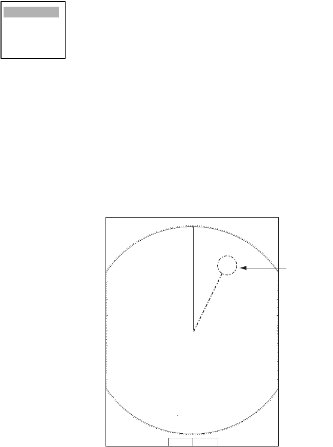
1. OPERATIONAL OVERVIEW
1-40
1.37 Antenna Speed
The antenna speed may be changed to meet operating requirement. Choose a high speed when
cruising at high speed to ensure timely update of radar targets. Note that the speed cannot be
changed on the 24 rpm motor; it is fixed at 24 rpm.
1. Press the MENU key to open the menu.
2. Choose the Echo menu and then press the ENTER key.
3. Choose Antenna Speed and then press the ENTER key.
4. Choose appropriate antenna speed. Auto/Range automatically changes antenna speed
according to range.
5. Press the ENTER key.
6. Press the MENU key to close the menu.
1.38 Waypoint Mark
The waypoint marker shows the location of the destination waypoint set on a navigation plotter.
You can turn this mark on or off as follows:
Waypoint mark
1. Press the MENU key to open the menu.
2. Choose Mark and then press the ENTER key.
3. Choose Waypoint Mark Display and then press the ENTER key.
4. Choose On or Off as appropriate and then press the ENTER key.
5. Press the MENU key to close the menu.
24rpm
36rpm
48rpm
Auto/Range
+ 110.1°R 2.525 NM
+
3
NM
0.5
+
Waypoi
nt
mark

1. OPERATIONAL OVERVIEW
1-41
1.39 Alarm Message Display
When a violation occurs the radar generates audible and visual alarms to alert you. The alarm
message display shows all alarms currently violated. You may show this display as follows:
1. Press the MENU key to open the menu.
2. Choose the Display menu and then press the ENTER key.
3. Choose Alarm Message and then press the ENTER key.
Alarm message display
To close the alarm message display, press any key.
List of alarm messages
List of alarm messages
Category Alarm name Alarm name
Signal missing
Heading Heading signal lost
Bearing Antenna rotation signal lost
Position Position data lost
Target Alarm
Target Alarm1 In (or Out) Echo has entered (or exited) target alarm zone 1.
Target Alarm1 In (or Out) Echo has entered (or exited) target alarm zone 1
ARP alarm
Collision CPA and TCPA of an ARP target is less than preset CPA and
TCPA.
Lost Acquired ARP target becomes lost
Target-Full Target tracking capacity is reached.
Proximity The range to an ARP target is less than the user-set proximity
alarm range.
AIS alarm
Collision CPA and TCPA of an ARP target is less than preset CPA and
TCPA.
Proximity The range to an AIS target is less than the user-set proximity
alarm range.
[Signal Missing]
[Target Alarm1]
[ARP Alarm]
<Please Push Any Key -- To Stop Alarm And Close this Window>
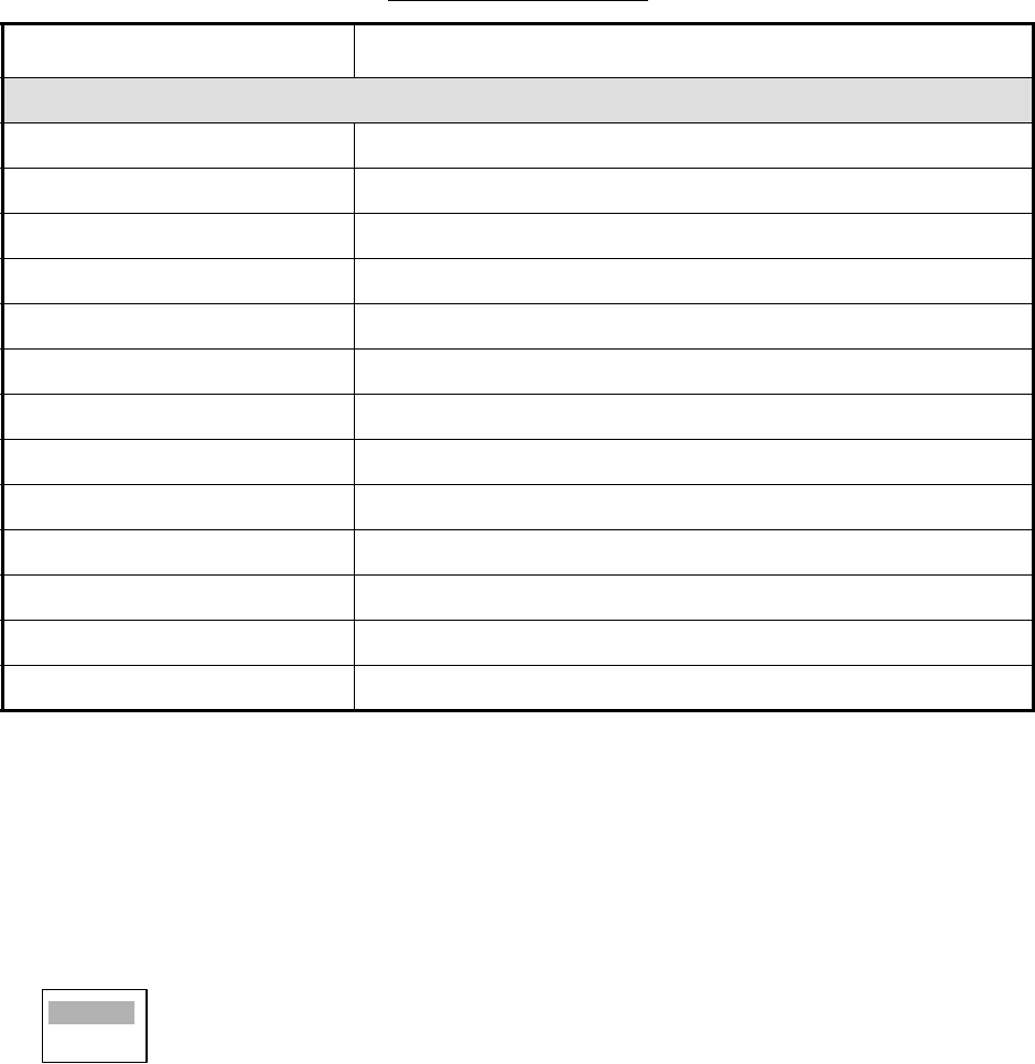
1. OPERATIONAL OVERVIEW
1-42
1.40 Echo Area
The effective display area can be either ellipsis or square shaped.
1. Press the MENU key to open the menu.
2. Choose the Display menu and then press the ENTER key.
3. Choose Echo Area and then press the ENTER key.
4. Choose desired display area configuration and then press the ENTER key.
5. Press the MENU to close the menu.
AIS system
TX TX stopped or TX error
ANT Antenna VSWR trouble
CH1 TDM2 RX1 board trouble
CH2 TDM2 RX2 board trouble
CH70 RX channel 70 trouble
FAIL System failure
EPFS External EPFS trouble
L/L Position data lost
SOG Speed data lost
COG Course data lost
HDG Heading data lost
ROT Rate of turn data lost
MKD Minimum input device lost
List of alarm messages
Category Alarm name Alarm name
Ellipsis
Square
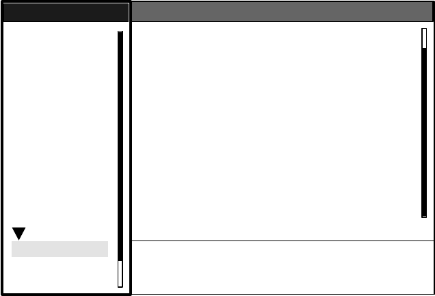
1. OPERATIONAL OVERVIEW
1-43
1.41 Customizing (Initial Menu)
The Initial sub menu in the System menu contains items which allow you to customize your radar
to meet your operational needs.
1.41.1 Opening the Initial menu
1. Press the MENU key to open the menu.
2. Roll the trackball to choose System followed by Initial and then press the ENTER key.
Initial menu
1.41.2 Description of Initial menu
Key Beep: A beep sounds when keys are pressed. You may turn this beep on or off.
Range Unit: Range may be shown in nm, km or sm.
Alarm Level: The target alarm may be set to sound against weak, medium or strong echoes.
TX Antenna Rotate: Radar pulses may be transmitted without rotating the antenna. For the ser-
vice technician.
Max Shift Speed: Set the maximum shift speed to use with automatic offcentering. The setting
range is 1-99 (kts)
STBY Mode Display: STBY Mode Display sets the function of the radar in standby. “Normal” dis-
plays “STBY” at the screen center; “Nav” displays navigation data, and “Economy” extinguishes
the backlight of the LCD to conserve power.
Bearing Source: Choose the type of bearing sensor connected to the radar; True (gyrocompass)
or Magnetic (magnetic compass).
S/T / W/X: Select
[ENTER]: Enter [CANCEL/HL OFF]: Back
[MENU]: Exit
GPS
Brill/Color
Echo
Mark
Target Trails
Custom 1
Display
Custom 2
Custom 3
Target
ARP
AIS
Manual Tune
Menu
Menu
Initial
Initial
System
Initial
Factory
Installation
Key Beep : On
Range Unit : nm
Alarm Level : Med
TX Antenna Rotate : Rotate
Max Shift Speed : 15 kt
STBY Mode Display : Normal
Bearing Source : Magnetic
Range Preset
Ship Speed Unit : kt
Depth Unit : m
Temperature Unit : °C
Wind Direction : Apparent
Wind Speed Unit : kt
Port 1 Setup : Auto
Port 2 Setup : Auto

1. OPERATIONAL OVERVIEW
1-44
Range Preset: You may choose the radar ranges you wish to use. When you choose Range
Preset the option window shown below appears. Choose a range and press the ENTER key to
turn that range on or off. At least two ranges must be turned on. The maximum range available
depends on radar model.
Available ranges
Ship Speed Unit: The ship’s speed unit may be selected to knots (kts), kilometers/hour (km/h) or
miles per hour (mph).
Depth Unit: The depth unit is available in meters (m), feet (ft), fathoms (fa), passi/braza (p/b) or
Hiro (hr).
Temperature Unit: Temperature may be displayed in °C (Celsius) or °F (Fahrenheit).
Wind Direction: Wind direction may be shown as True or Apparent. For further details, see para-
graph 1.35.1.
Wind Speed Unit: Wind speed may be shown in knots (kts), kilometers per hour (km/h), miles per
hour (mph) or meters/second (m/s).
Port 1: Set the baud rate of the equipment connected to Port1. “Auto” provides automatic detec-
tion of baud rate. External equipment must be equipped with auto baud rate detection feature.
Port 2: Same function as Port1 but for Port2.
Through Output: Data input to port 1 may be output from port 2. Choose “On” to use this feature.
0.125 On
0.25 On
0.5 On
0.75 On
1Off
1.5 On
2Off
3On
4Off
6On
8Off
12 On
16 On
24 On
36 On
48 On
72 On
96 On
Exit? Yes
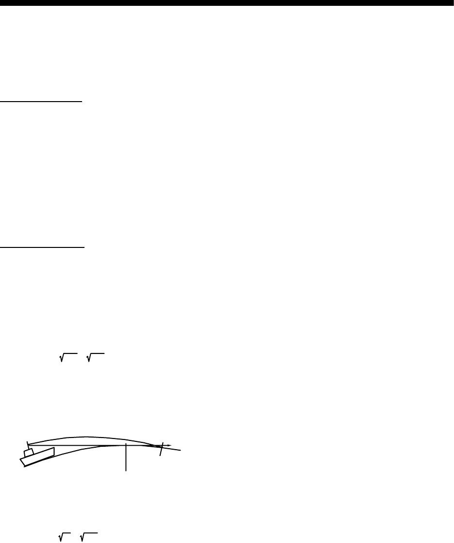
2-1
2. RADAR OBSERVATION
2.1 General
2.1.1 Minimum and maximum ranges
Minimum range
The minimum range is defined by the shortest distance at which, using a scale of 1.5 or 0.75 nm,
a target having an echoing area of 10 m2 is still shown separate from the point representing the
antenna position.
It is mainly dependent on the pulse length, antenna height, and signal processing such as main
bang suppression and digital quantization. It is a good practice to use a shorter range scale as far
as it gives favorable definition or clarity of picture. The IMO Resolution MSC.64(67) Annex 4 (Ship-
borne radar) and A.820: 1995 (High Speed Craft Radar) require the minimum range to be less
than 50 m and 35 m, respectively. This series of radars satisfy this requirement.
Maximum range
The maximum detecting range of the radar, Rmax, varies considerably depending on several fac-
tors such as the height of the antenna above the waterline, the height of the target above the sea,
the size, shape and material of the target, and the atmospheric conditions.
Under normal atmospheric conditions, the maximum range is equal to the radar horizon or a little
shorter. The radar horizon is longer than the optical one by about 6% because of the diffraction
property of the radar signal. The Rmax is given in the following equation.
where Rmax: radar horizon (nautical miles)
h1: antenna height (m)
h2: target height (m)
For example, if the height of the antenna above the waterline is 9 meters and the height of the
target is 16 meters, the maximum radar range is;
It should be noted that the detection range is reduced by precipitation (which absorbs the radar
signal).
R
max
= 2.2 x ( h1 +h2 )
Radar horizon
Optical horizon
R
m
ax
= 2.2 x ( 9 + 16 ) = 2.2 x (3 + 4) = 15.4 nm

2. RADAR OBSERVATION
2-2
2.1.2 X-band and S-band
In fair weather, the equation on the previous page does not give a significant difference between
X- and S-band radars. However, in heavy precipitation condition, an S-band radar would have
better detection than an X-band radar.
2.1.3 Radar resolution
There are two important factors in radar resolution (discrimination): bearing resolution and range
resolution.
Bearing resolution
Bearing resolution is the ability of the radar to display as separate pips the echoes received from
two targets which are at the same range and close together. It is proportional to the antenna length
and reciprocally proportional to the wavelength. The length of the antenna radiator should be
chosen for a bearing resolution better than 2.5Åã (IMO Resolution). This condition is normally sat-
isfied with a radiator of 1.2 m (4 ft) or longer in the X-band. The S-band radar requires a radiator
of about 12 feet (3.6 m) or longer.
Range resolution
Range resolution is the ability to display as separate pips the echoes received from two targets
which are on the same bearing and close to each other. This is determined by pulse length only.
Practically, a 0.08 microsecond pulse offers the discrimination better than 35 m as do so with all
FURUNO radars.
Test targets for determining the range and bearing resolution are radar reflectors having an
echoing area of 10 m2.
2.1.4 Bearing accuracy
One of the most important features of the radar is how accurately the bearing of a target can be
measured. The accuracy of bearing measurement basically depends on the narrowness of the
radar beam. However, the bearing is usually taken relative to the ship's heading, and thus, proper
adjustment of the heading line at installation is an important factor in ensuring bearing accuracy.
To minimize error when measuring the bearing of a target, put the target echo at the extreme posi-
tion on the screen by selecting a suitable range.
2.1.5 Range measurement
Measurement of the range to a target is also a very important function of the radar. Generally,
there are two means of measuring range: the fixed range rings and the variable range marker
(VRM). The fixed range rings appear on the screen with a predetermined interval and provide a
rough estimate of the range to a target. The variable range marker's diameter is increased or
decreased so that the marker touches the inner edge of the target, allowing the operator to obtain
more accurate range measurements.
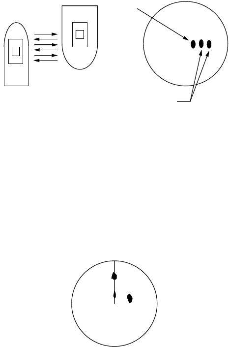
2. RADAR OBSERVATION
2-3
2.2 False Echoes
Occasionally echo signals appear on the screen at positions where there is no target or disappear
even if there are targets. They are, however, recognized if you understand the reason why they
are displayed. Typical false echoes are shown below.
2.2.1 Multiple echoes
Multiple echoes occur when a transmitted pulse returns from a solid object like a large ship, bridge,
or breakwater. A second, a third or more echoes may be observed on the display at double, triple
or other multiples of the actual range of the target as shown below. Multiple reflection echoes can
be reduced and often removed by decreasing the gain (sensitivity) or properly adjusting the SEA
control.
Multiple echoes
2.2.2 Sidelobe echoes
Every time the radar pulse is transmitted, some radiation escapes on each side of the beam,
called "sidelobes." If a target exists where it can be detected by the side lobes as well as the main
lobe, the side echoes may be represented on both sides of the true echo at the same range. Side
lobes show usually only on short ranges and from strong targets. They can be reduced through
careful reduction of the gain or proper adjustment of the SEA control.
Sidelobe echoes
Own ship
Target
True
echo
Multiple
echo
Target B
(True)
Target B
(Spurious)
Target A
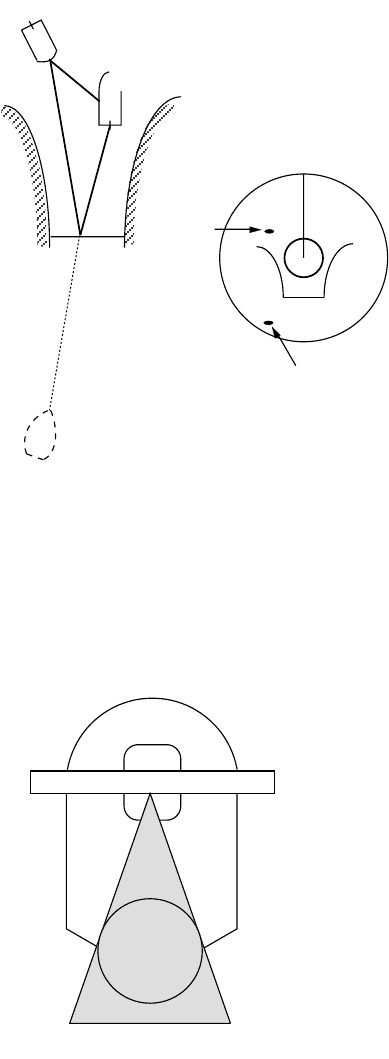
2. RADAR OBSERVATION
2-4
2.2.3 Virtual image
A relatively large target close to your ship may be represented at two positions on the screen. One
of them is the true echo directly reflected by the target and the other is a false echo which is
caused by the mirror effect of a large object on or close to your ship as shown in the figure below.
If your ship comes close to a large metal bridge, for example, such a false echo may temporarily
be seen on the screen.
Virtual image
2.2.4 Shadow sector
Funnels, stacks, masts, or derricks in the path of the antenna block the radar beam. If the angle
subtended at the antenna is more than a few degrees, a non-detecting sector may be produced.
Within this sector targets can not be detected.
Shadow sectors
True
echo
False
echo
Own ship
Target ship
Mirror image
of target ship
Radar
antenna
Radar
mast
Shadow sector
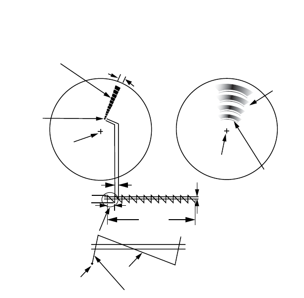
2. RADAR OBSERVATION
2-5
2.3 SART (Search and Rescue Transponder)
2.3.1 SART description
A Search and Rescue Transponder (SART) may be triggered by any X-Band (3 cm) radar within
a range of approximately 8 nm. Each radar pulse received causes it to transmit a response which
is swept repetitively across the complete radar frequency band. When interrogated, it first sweeps
rapidly (0.4 µs) through the band before beginning a relatively slow sweep (7.5 µs) through the
band back to the starting frequency. This process is repeated for a total of twelve complete cycles.
At some point in each sweep, the SART frequency will match that of the interrogating radar and
be within the pass band of the radar receiver. If the SART is within range, the frequency match
during each of the 12 slow sweeps will produce a response on the radar display, thus a line of 12
dots equally spaced by about 0.64 nautical miles will be shown.
When the radar to the SART is reduced to about 1 nm, the radar display my show also the 12
responses generated during the fast sweeps. These additional dot responses, which also are
equally spaced by 0.64 nautical miles, will be interspersed with the original line of 12 dots. They
will appear slightly weaker and smaller than the original dots.
Appearance of SART echo
9500 MHz
9200 MHz
Radar antenna
beamwidth
Screen A: When SART
is distant Screen B: When SART
is close
Lines of 12 dots
are displayed in
concentric arcs.
Echo from SART
Position of
SART
Own ship
position Own ship
position
SART mark
length Radar receiver
bandwidth
Sweep time
7.5 µs 95 µs
Sweep start High speed sweep signal
Low speed sweep signal
24 NM 1.5 NM
Position of
SART
Echo from
SART

2. RADAR OBSERVATION
2-6
2.3.2 General remarks on receiving SART
SART range errors
When responses from only the 12 low frequency sweeps are visible (when the SART is at a range
greater than about 1 nm), the position at which the first dot is displayed may be as much as 0.64
nm beyond the true position of the SART. When the range closes so that the fast sweep responses
are seen also, the first of these will be no more than 150 meters beyond the true position.
Radar bandwidth
This is normally matched to the radar pulse length and is usually switched with the range scale
and the associated pulse length. Narrow bandwidths of 3-5 MHz are used with long pulses on long
range scales and wide bandwidths of 10-25 MHz with short pulses on short ranges.
A radar bandwidth of less than 5 MHz will attenuate the SART signal slightly, so it is preferable to
use a medium bandwidth to ensure optimum detection of the SART.
Radar side lobes
As the SART is approached, side lobes from the radar antenna may show the SART responses
as a series of arcs or concentric rings. These can be removed by the use of the anti-clutter sea
control although it may be operationally useful to observe the side lobes as they may be easier to
detect in clutter conditions and also they will confirm that the SART is near to own ship.
Note: SART information excerpted from IMO SN/Circ 197 OPERATION OF MARINE RADAR
FOR SART DETECTION.
2.4 RACON
A RACON is a radar beacon which emits radar receivable signals in the radar frequency spectrum
(X- or S-band). There are several signal formats; in general, the RACON signal appears on the
radar screen as a rectangular echo originating at a point just beyond the position of the radar
beacon. It has a Morse coded pattern. Note that the position on the radar display is not accurate.
RACON
RACON
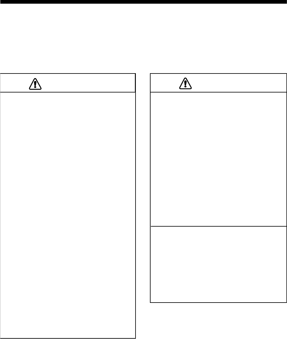
3-1
3. ARP OPERATION
The Automatic Radar Plotter ARP-11 (option) manually or automatically acquires and tracks ten
targets. Once a target is acquired automatically or manually it is automatically tracked within 0.1
to 32 nm.
3.1 Usage Precautions
No one navigational aid should be relied
upon for the safety of vessel and crew.
The navigator has the responsibility to
check all aids available to confirm
position. Electronic aids are not
a substitute for basic navigational
principles and common sense.
• This auto plotter automatically tracks an
automatically or manually acquired radar
target and calculates its course and
speed, indicating them by a vector. Since
the data generated by the auto plotter
are based on what radar targets are
selected, the radar must always be
optimally tuned for use with the auto
plotter, to ensure required targets will not
be lost or unwanted targets such as sea
returns and noise will not be acquired
and tracked.
• A target does not always mean a land-
mass, reef, ships or other surface vessels
but can imply returns from sea surface
and clutter. As the level of clutter changes
with environment, the operator should
properly adjust the A/C SEA, A/C RAIN
and GAIN controls to be sure target
echoes are not eliminated from the
radar screen.
CAUTION
CAUTION
The plotting accuracy and response of
this auto plotter meets IMO standards.
Tracking accuracy is affected by the
following:
• Tracking accuracy is affected by course
change. One to two minutes is required to
restore vectors to full accuracy after an
abrupt course change. (The actual
amount depends on gyrocompass
specifications.)
• The amount of tracking delay is inversely
proportional to the relative speed of the
target. Delay is on the order of 15-30
seconds for high relative speed; 30-60
seconds for low relative speed.
Display accuracy is affected by the
following:
• Echo intensity
• Radar transmission pulsewidth
• Radar bearing error
• Gyrocompass error
• Course change (own ship or target)
CAUTION
CAUTION
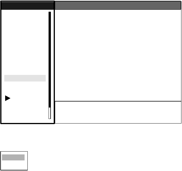
3. ARP OPERATION
3-2
3.2 Controls for Use with ARP
ENTER: Acquires cursor-selected target; Displays data for tracked target (in the data box at the
bottom of the screen).
CANCEL/HL OFF: Removes data of cursor-selected tracked target from the data box; stops
tracking cursor-selected (when its data is not displayed in the data box.
MENU: Accesses the Target and ARP menus for ARP operations.
Trackball: Chooses target to acquire, cancel tracking or show target data.
3.3 ARP Display On/Off
You may turn off the ARP display as shown below.
1. Press the MENU key to display the main menu.
2. Use the trackball to choose ARP and then press the ENTER key.
ARP menu
3. Use the trackball to choose Display and then press the ENTER key.
4. Choose Off or On as appropriate and then press the ENTER key.
5. Press the MENU key to close the menu.
GPS
Brill/Color
Echo
Mark
Target Trails
Custom 1
Display
Custom 2
Custom 3
Target
ARP
AIS
Manual Tune
Menu
Menu
ARP
ARP
System
DIsplay : Off
Symbol Color : Green
Auto Acquire : Off
All Cancel : No
S/T / W/X: Select
[ENTER]: Enter [CANCEL/HL OFF]: Back
[MENU]: Exit
Off
On
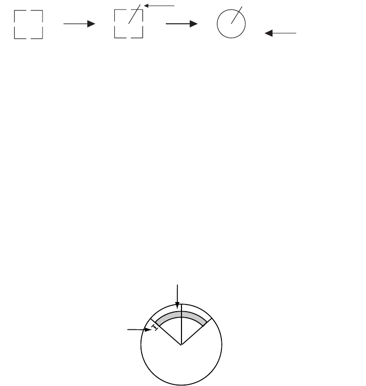
3. ARP OPERATION
3-3
3.4 Acquiring and Tracking Targets
Ten targets may be acquired and tracked manually and automatically. When you attempt to
acquire an 11th target, the message "ARP FULL - ALREADY TRACKING 10 TARGETS!" appears
for five seconds. To acquire another target, terminate tracking of an unnecessary target, as shown
in the paragraph 3.5.
3.4.1 Manual acquisition
When the automatic acquisition (AUTO ACQ. AREA) is set to on, up to five targets may be
acquired manually. If you attempt to acquire a sixth target, the alert message appears.
1. Place the cursor on the target to acquire.
2. Press the ENTER key.
The plot symbol changes over time as below. A vector appears about one minute after acquisition,
indicating the target's motion trend.
ARP target mark
3.4.2 Automatic acquisition
The ARP can acquire up to ten targets automatically by setting an automatic acquisition area.
When automatic acquisition is selected after acquiring targets manually, only the remaining
capacity for targets may be automatically acquired. For example, if seven targets have been man-
ually acquired, three targets may be automatically acquired.
The automatic acquisition area is 2.0 to 2.5 miles in range and ±45° on either side of the heading
line in bearing.Targets being tracked in automatic acquisition are continuously tracked when
switching to manual acquisition. Note that targets being tracked in automatic acquisition are con-
tinuously tracked when switching to manual acquisition.
Automatic acquisition area
1. Press the MENU key to show the main menu.
2. Choose ARP and then press the ENTER key
At acquisition 1 min. after
acquisition 3 min. after
acquisition
Vector
01 01 01 Target number
Automatic acquisition area
45° port 45° starboard
2.0 - 2.5 nm

3. ARP OPERATION
3-4
3. Choose Auto Acquire and then press the ENTER key.
4. Choose On to enable automatic acquisition.
5. Press the ENTER key.
6. Press the MENU key to close the menu.
3.5 Terminating Tracking of ARP Targets
When ten targets have been acquired, no more acquisition occurs unless targets are cancelled. If
you need to acquire additional targets, you must first cancel one or more individual targets, or all
targets, using one of the procedures below.
3.5.1 Terminating tracking of selected targets
1. Place the cursor on the target to terminate tracking.
2. Press the CANCEL/HL OFF key to terminate tracking and erase the target.
3.5.2 Terminating tracking of all targets
1. Press the MENU key to open the menu.
2. Choose ARP and then press the ENTER key.
3. Choose All Cancel and then press the ENTER key.
4. Choose Yes.
5. Press the ENTER key.
6. Press the MENU key to close the menu.
Off
On
No
Yes
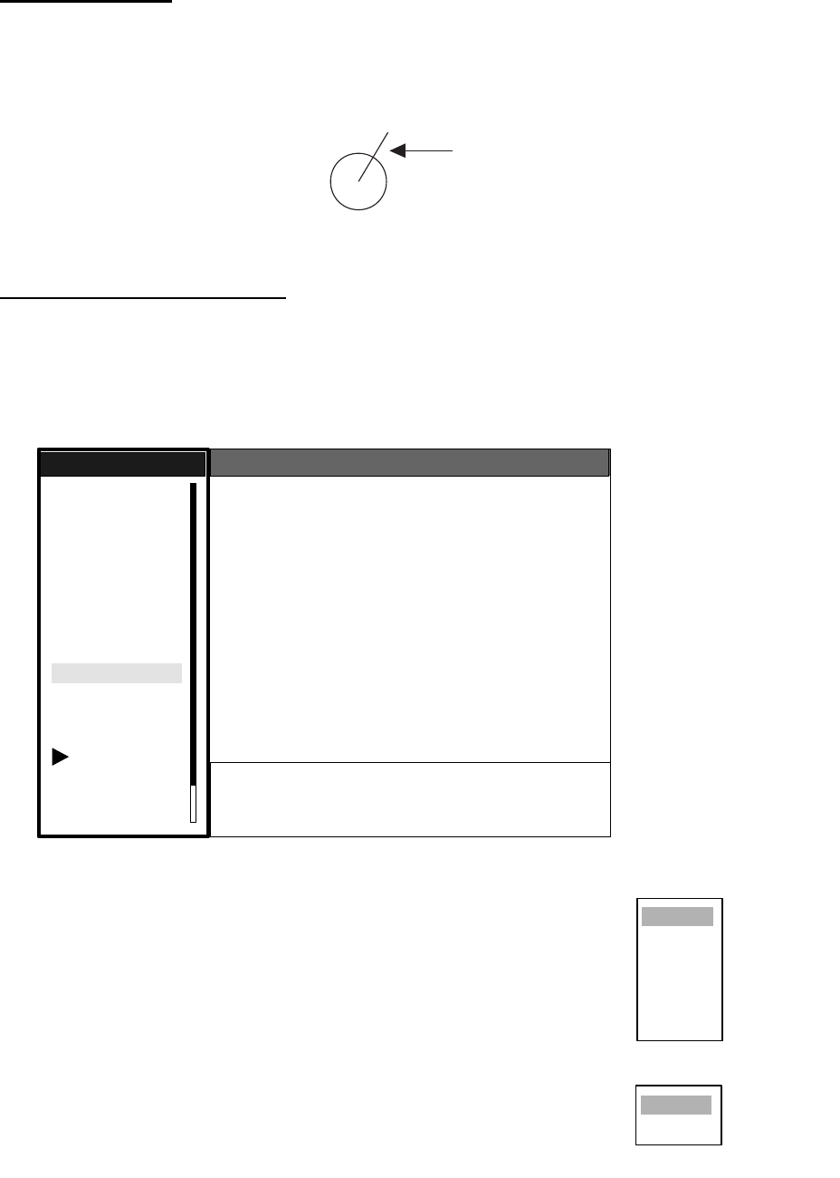
3. ARP OPERATION
3-5
3.6 Vector Attributes
What is a vector?
A vector is a line extending from a tracked target which shows estimated speed and course of the
target. The vector tip shows an estimated position of the target after the selected vector time
elapses. It can be useful to extend the vector length (time) in order to evaluate the risk of collision
with any target.
Vector
Vector time, vector reference
Vector time can be set to 30 seconds, 1, 3, 6, 15 or 30 minutes. You may reference the vectors to
North (True, requires heading and speed data) or ship's heading (relative) as desired.
1. Press the MENU key to open the menu.
2. Choose Target and then press the ENTER key.
Target menu
3. Choose Vector Time and then press the ENTER key.
4. Choose desired vector time and then press the ENTER key.
5. Choose Vector Reference and then press the ENTER key.
6. Choose Relative or True as appropriate and then press the
ENTER key.
7. Press the MENU key to close the menu.
Note: The functions of the Target menu are commonly shared by ARP
and AIS.
Vector
GPS
Brill/Color
Echo
Mark
Target Trails
Custom 1
Display
Custom 2
Custom 3
Target
ARP
AIS
Manual Tune
Menu
Menu
Target
Target
System
Vector Time : 6 min
Vector Reference : Relative
History Dots : 5
History Intervals : 1 min
CPA : 1 nm
TCPA : 1 min
Proximity Alarm : Off
S/T / W/X: Select
[ENTER]: Enter [CANCEL/HL OFF]: Back
[MENU]: Exit
30sec
1min
3min
6min
15min
30min
Relative
True
Vector time choices
Vector reference choice
s
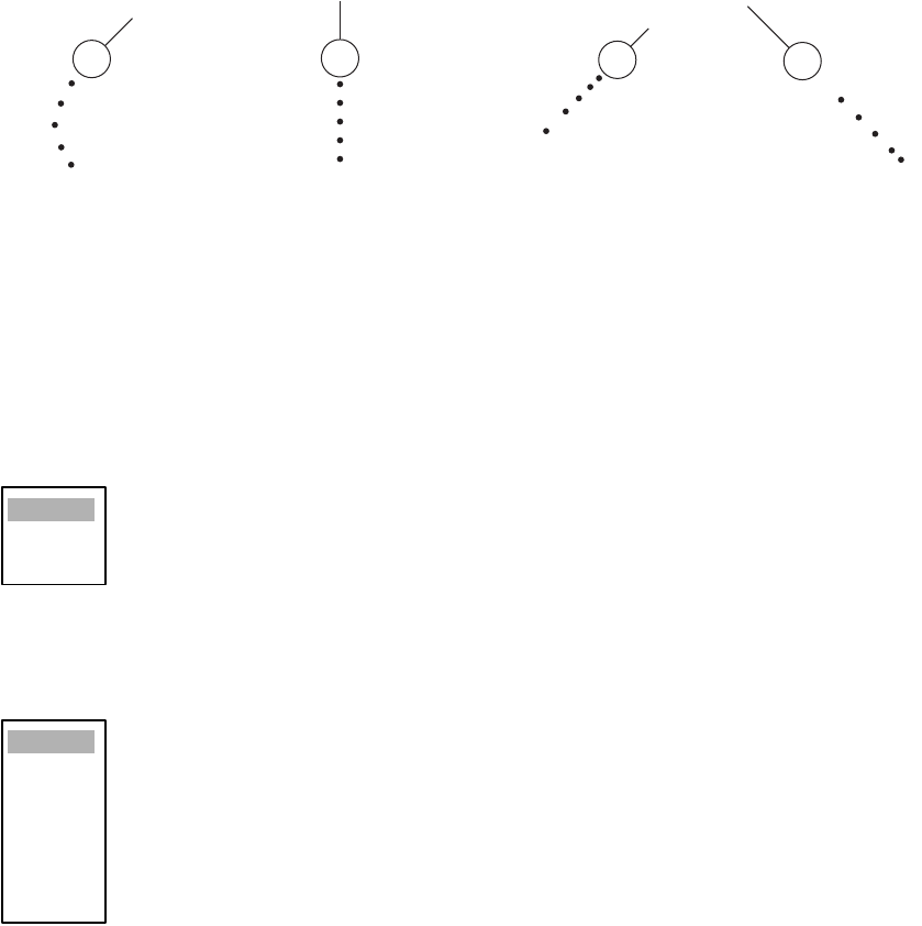
3. ARP OPERATION
3-6
3.7 History Display (target past position)
This radar can display time-spaced dots (maximum ten dots) marking the past positions of any
ARP/AIS target being tracked. You can evaluate a target's actions by the spacing between dots.
Below are examples of dot spacing and target movement..
Target movement and history display
You may choose the number of history dots to display and the time interval to display them.
1. Press the MENU key to open the menu.
2. Choose Target and then press the ENTER key.
3. Choose History Dots and then press the ENTER key.
4. Choose number of history dots to display (5 or 10) or choose Off to turn off the history display.
5. Press the ENTER key.
6. Choose History Interval and then press the ENTER key.
7. Choose appropriate time interval and then press the ENTER key.
8. Press the MENU key to close the menu.
(a) Ship turning (b) Ship running
straight (c) Ship reduced
speed
(d) Ship increased
speed
Off
5
10
15sec
30sec
1min
2min
3min
6min
12min
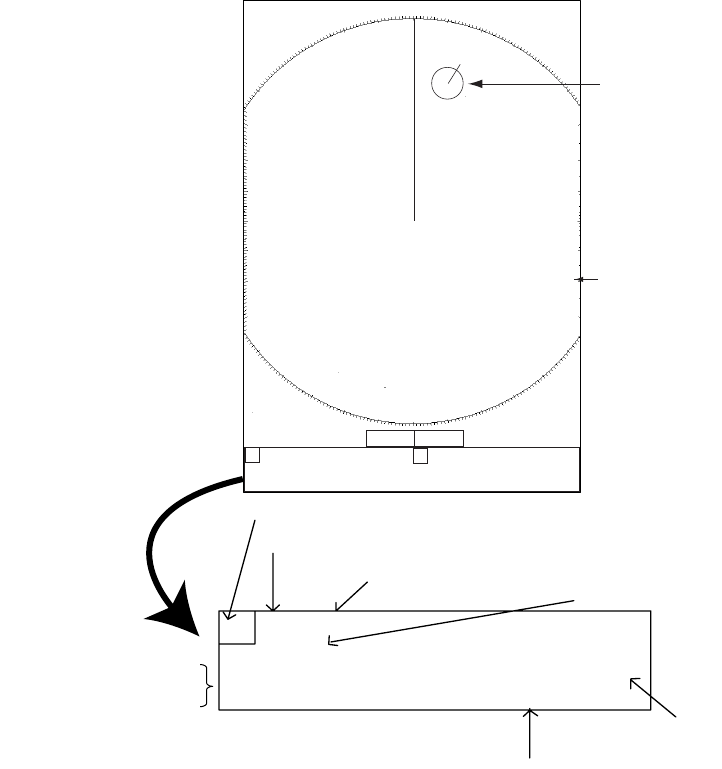
3. ARP OPERATION
3-7
3.8 ARP Target Data
You can show target data (range, bearing, course, speed, CPA and TCPA) for two tracked ARP
targets, in the data box at the bottom of the screen. To display ARP target data, the ARP display
must be active and the menu item Data Box in the Display sub menu must be set for Target or All.
1. Place the cursor on the ARP target for which you want to know its data.
2. Press the ENTER key to show the target’s data.
ARP target data
The data for the chosen target is displayed in data box A or B. The box is chosen on a first-in, first-
out basis. For example, if both data box A and data box B are currently showing data and an ARP
target is selected to show its data, the data in data box A will be erased and replaced with the data
of the newly selected ARP target.
To remove a target’s data, choose the appropriate data box and press the CANCEL/HL OFF key.
AB
BRG 016.4
°
R RNG 00.65NM CPA 00.60NM
CSE 018.4
°
M SPD 12.34kt TCPA 10:00
A
TRUE 5 min
Data box (A or B)
Vector reference
Vector time
Target no.
Time to CPA
CP
A
No.10
Data box A Data box B
B
earing, range, CPA
C
ourse, speed, TCPA
+ 110.1°R 2.525 NM
+
3
NM
0.5
Cursor
+
ARP Targe
t
+
3. ARP OPERATION
3-8
3.9 CPA and TCPA Alarm
When the predicted CPA of any ARP/AIS target becomes smaller than a preset CPA alarm range
or its predicted TCPA less than a preset TCPA alarm limit, an audio alarm sounds and the collision
visual alarm is generated.. In addition, the target plot symbol of the offending target changes to a
triangle and flashes together with its vector. You may silence the audio alarm and acknowledge
the alarm with the CANCEL/HL OFF key. The flashing of the triangle plot symbol continues until
you intentionally terminate tracking of the target. The ARP continuously monitors the predicted
range at the Closest Point of Approach (CPA) and predicted time to CPA (TCPA) of each track to
own ship.
This feature helps alert you to targets which may be on a collision course with own ship. However,
it is important that GAIN, SEA, RAIN and other radar controls are properly adjusted and the ARP
is set up so that it can track targets effectively..
1. Press the MENU key to open the menu.
2. Choose Target and then press the ENTER key.
3. Choose CPA and then press the ENTER key.
4. Choose appropriate time and then press the ENTER key.
5. Choose TCPA and then press the ENTER key.
6. Choose appropriate TCPA and then press the ENTER key.
7. Press the MENU key to close the menu.
CAUTION
The CPA/TCPA alarm should never be
relied upon as the sole means for detect-
ing the risk of collision. The navigator is
not relieved of the responsibility to keep
visual lookout for avoiding collisions,
whether or not the radar or other plotting
aid is in use.
Off
0.5nm
1nm
2nm
3nm
5nm
6nm
30sec
1min
2min
3min
4min
5min
6min
12min

3. ARP OPERATION
3-9
3.10 Proximity Alarm
The proximity alerts you by audio and visual alarms when an ARP/AIS target is within the range
you specify.
1. Press the MENU key to open the menu.
2. Choose Target and then press the ENTER key.
3. Choose Proximity Alarm and then press the ENTER key.
4. Choose appropriate range and then press the ENTER key.
5. Press the MENU key to close the menu.
3.11 Lost Target
When the system detects a lost target, the target symbol becomes a diamond and tracking is dis-
continued after one minute.
Lost target mark
Canceling a lost target
Place the cursor on the target and then press the CANCEL/HL OFF key.
Off
0.5nm
1nm
2nm
3nm
5nm
6nm
12nm
24nm
01

3. ARP OPERATION
3-10
3.12 Symbol Color
You may choose the ARP/AIS symbol color from among Green, Red, Blue, White or Black.
1. Press the MENU key to open the menu.
2. Choose ARP and then press the ENTER key.
3. Choose Symbol Color and then press the ENTER key.
4. Choose appropriate color and then press the ENTER key.
5. Press the MENU key to close the menu.
Green
Red
Blue
White
Black
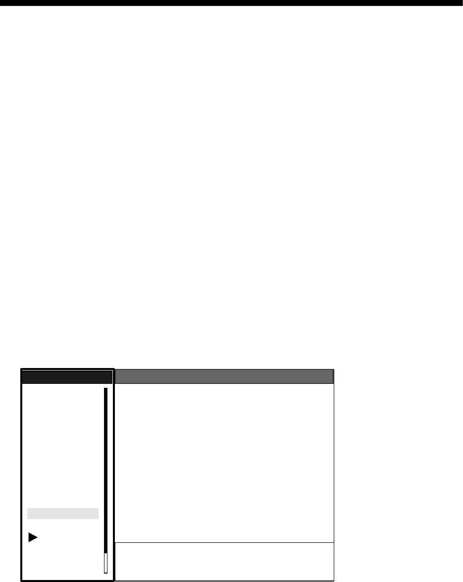
4-1
4. AIS OPERATION
Connected to an AIS Transponder via an AIS Interface, the FR-8xx2 series can show the name,
position and other nav data of the nearest 100 AIS transponder-equipped ships.
This radar accepts position data fixed by WGS-84 geodetic datum. Set the datum to WGS-84 on
the GPS navigator connected to this radar. If other type of datum is input, the error message
"DATUM" appears and the AIS feature is inoperative.
4.1 Controls for Use with AIS
ENTER: Displays data for cursor-selected active AIS target (in the data box at the bottom of the
screen).
CANCEL/HL OFF: Removes data of cursor-selected AIS target from the data box.
MENU: Accesses the Target and AIS menus for AIS operations.
Trackball: Chooses active target to display its data.
4.2 Turning the AIS Display On or Off
You may turn the AIS display on or off. The system continues processing of AIS targets regardless
of whether the AIS display is on or off, provided it has been activated.
1. Press the MENU key to display the main menu.
2. Choose AIS and then press the ENTER key.
AIS menu
3. Choose DIsplay and then press the ENTER key.
4. Choose Off or On as appropriate and then press the ENTER key.
5. Press the MENU key to close the menu.
GPS
Brill/Color
Echo
Mark
Target Trails
Custom 1
Display
Custom 2
Custom 3
Target
ARP
AIS
Manual Tune
Menu
Menu
AIS
AIS
System
Display : Off
Symbol Color : Green
Range : 3.0nm
Sector Start : 340
Sector End : 20
Sort By : Range
Number of Target : 100
S/T / W/X: Select
[ENTER]: Enter [CANCEL/HL OFF]: Back
[MENU]: Exit
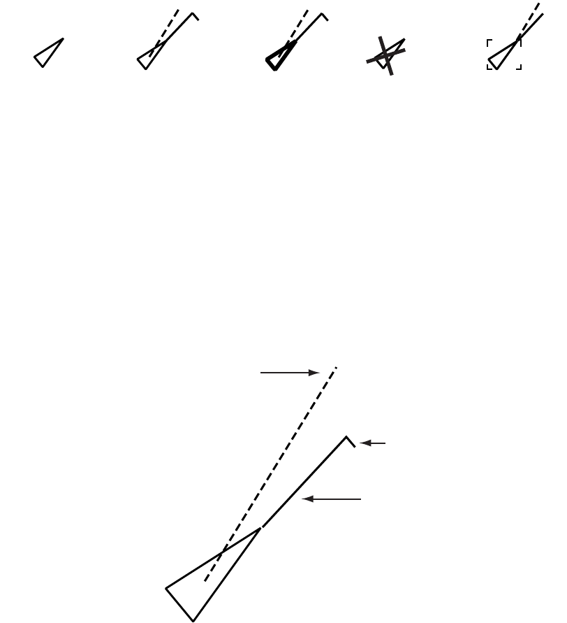
4. AIS OPERATION
4-2
4.3 AIS Symbols
When the AIS is turned on, AIS targets are marked with appropriate AIS symbol as below.
AIS symbols
Note 1: AIS symbols are momentarily erased after the screen is redrawn when the heading is
changed in the Head-up mode.
Note 2: When no AIS data is received, the message "RECEIVE" appears in the text window.
Check the AIS transponder.
4.4 Activating Targets
When you convert a sleeping target to an activated target, that target's course and speed are
shown with a vector. You can easily judge target movement by monitoring the vector.
Appearance of an active target
To activate or sleep a target, place the cursor on the target and press the ENTER key.
Sleeping target Activated target Dangerous
target
Lost target Target selected
for data display
Heading line
COG (Course over Ground) vector
(If there is no heading data,
the line points in direction of COG.)
Rate of turn
(ROT)
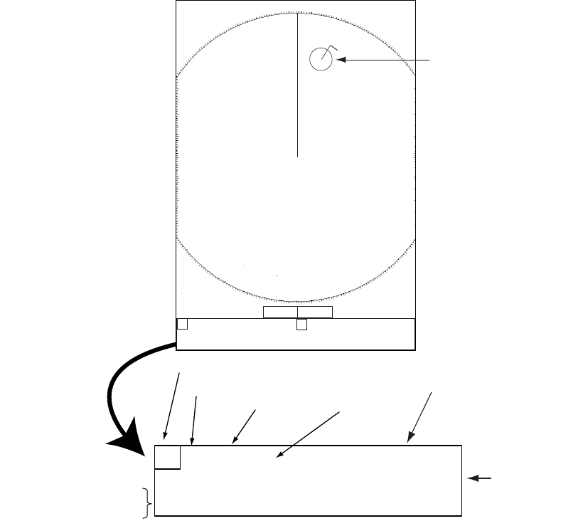
4. AIS OPERATION
4-3
4.5 Displaying AIS Target Data
Place the cursor on the active target that you want to know its data.
AIS data
The data for the chosen target is displayed in data box A or B. The box is chosen on a first-in, first-
out basis. For example, if both data box A and data box B are currently showing data and an AIS
target is selected to show its data, the data in data box A will be erased and replaced with the data
of the newly selected AIS target.
To remove a target’s data, choose the appropriate data box and press the CANCEL/HL OFF key.
AB
Data box A Data box B
+ 110.1°R 2.525 NM
+
3
NM
0.5
+
AIS Target
+
BRG 123.4°R RNG 23.45NM CPA 10.00NM
CSE 303.4°M SPD 12.34kt TCPA 10:00
ATRUE 5 min MMSI: *********
Data box (A or B)
Vector reference
Vector time
MMSI of vessel
Length, Bea
m
of vessel
NAME: PEGASUS
LENGTH: 100M BEAM: 45M
Name of
vessel
B
earing, range, CPA
C
ourse, speed, TCPA
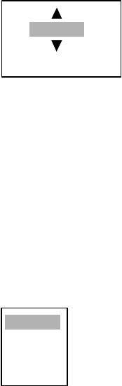
4. AIS OPERATION
4-4
4.6 Display Range
You may set the AIS target display range as below. This allows you to view only those AIS targets
within the range you specify. The setting range is 0-96 miles but actual range depends on the con-
nected AIS Transponder. If the target sorting method is selected to “Range,” the target data within
the range set here are transmitted to this radar.
1. Press the MENU key to open the menu.
2. Choose AIS and then press the ENTER key.
3. Choose Range and then press the ENTER key.
4. Use the trackball to set the display range and then press the ENTER key.
5. Press the MENU key to close the menu.
4.7 Sorting Targets
You may sort AIS targets by range from own ship, by sector, by CPA or TCPA.
1. Press the MENU key to open the menu.
2. Choose AIS and then press the ENTER key.
3. Choose Range and then press the ENTER key.
4. Use the trackball to choose desired sorting method and then press the ENTER key. For
“Sector”, the data for targets within the sector are transmitted to this radar.
5. Press the MENU key to close the menu.
3nm
(0.1nm-96.0nm)
Range
Sector
CPA
TCPA
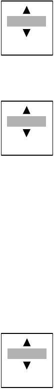
4. AIS OPERATION
4-5
4.8 Display Sector
You may choose the area where to display AIS targets. The range of the sector may be from 0°
to 359°.
1. Press the MENU key to open the menu.
2. Choose AIS and then press the ENTER key.
3. Choose Sector Start and then press the ENTER key.
4. Use the trackball to set the starting point for the sector and then press the ENTER key.
5. Choose Sector End and then press the ENTER key.
6. Use the trackball to set the end point for the sector and then press the ENTER key.
7. Press the MENU key to close the menu.
4.9 Number of Targets to Display
You may choose the number of AIS targets to display, from 10-100. This feature is useful when
the screen becomes cluttered with AIS targets.
1. Press the MENU key to open the menu.
2. Choose AIS and then press the ENTER key.
3. Choose Number of Targets and then press the ENTER key.
4. Use the trackball to choose the number of targets to display and then press the ENTER key.
Press the MENU key to close the menu.
340
(0-359)
20
(0-359)
100
(0-100)
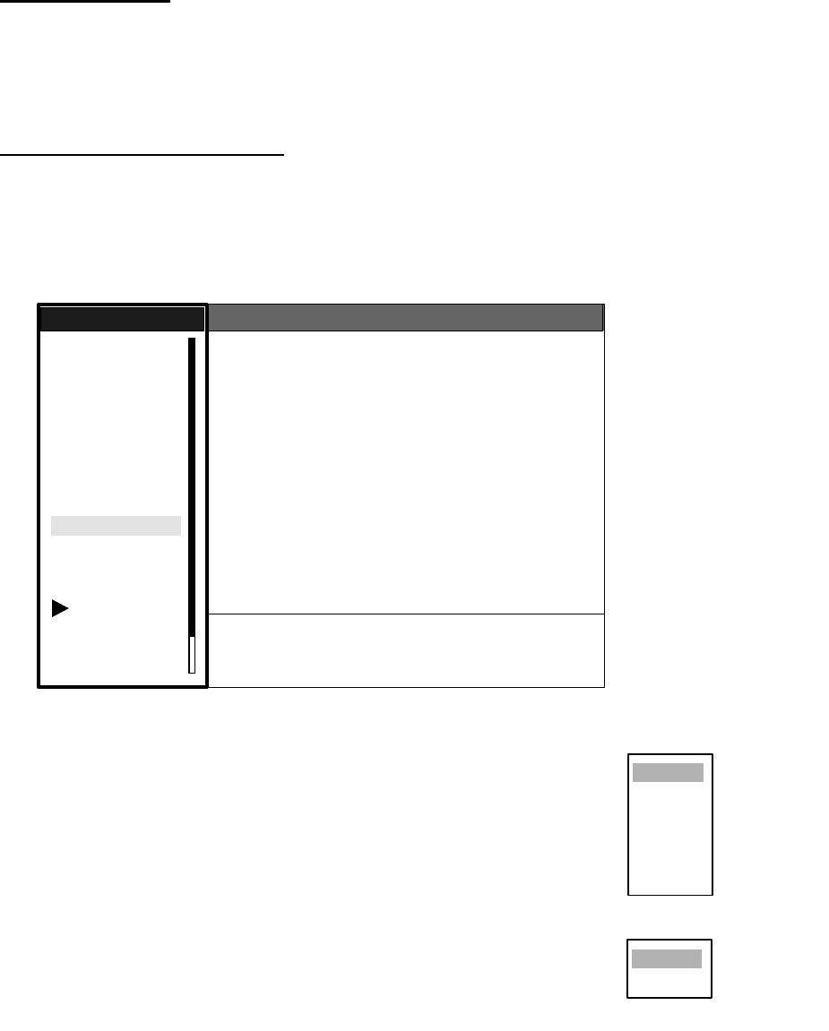
4. AIS OPERATION
4-6
4.10 Vector Attributes
What is a vector?
A vector is a line extending from a tracked target which shows estimated course of the AIS target.
The vector tip shows an estimated position of the target after the selected vector time elapses. It
can be useful to extend the vector length (time) in order to evaluate the risk of collision with any
target. (See the illustration on page 4-2 for the appearance of a vector.)
Vector time, vector reference
Vector time can be set to 30 seconds, 1, 3, 6, 15 or 30 minutes. You may reference the vectors to
North (True, requires heading and speed data) or ship's heading (relative) as desired.
1. Press the MENU key to open the menu.
2. Choose Target and then press the ENTER key.
Target menu
3. Choose Vector Time and then press the ENTER key.
4. Choose desired vector time and then press the ENTER key.
5. Choose Vector Reference and then press the ENTER key.
6. Choose Relative or True as appropriate and then press the ENTER
key.
7. Press the MENU key to close the menu.
GPS
Brill/Color
Echo
Mark
Target Trails
Custom 1
Display
Custom 2
Custom 3
Target
ARP
AIS
Manual Tune
Menu
Menu
Target
Target
System
Vector Time : 6 min
Vector Reference : Relative
History Dots : 5
History Intervals : 1 min
CPA : 1 nm
TCPA : 1 min
Proximity Alarm : Off
S/T / W/X: Select
[ENTER]: Enter [CANCEL/HL OFF]: Back
[MENU]: Exit
30sec
1min
3min
6min
15min
30min
Relative
True
Vector time choices
Vector reference choice
s
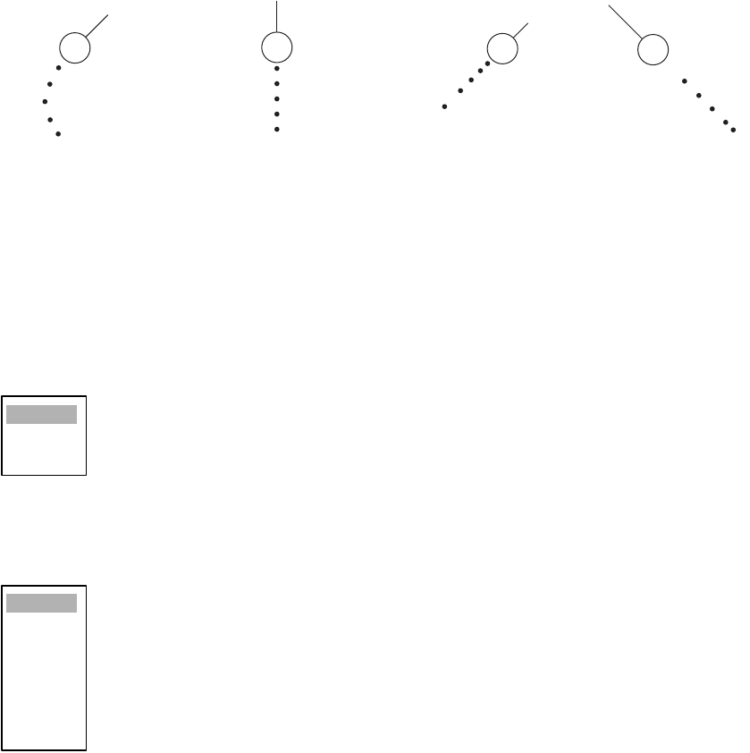
4. AIS OPERATION
4-7
4.11 History Display (target past position)
This radar can display time-spaced dots (maximum ten dots) marking the past positions of any
ARP/AIS target being tracked. You can evaluate a target's actions by the spacing between dots.
Below are examples of dot spacing and target movement.
Target movement and history display
You may choose the number of history dots to display and the time interval to display them.
1. Press the MENU key to open the menu.
2. Choose Target and then press the ENTER key.
3. Choose History Dots and then press the ENTER key.
4. Choose number of history dots to display (5 or 10) or choose Off to turn off the history display.
5. Press the ENTER key.
6. Choose History Interval and then press the ENTER key.
7. Choose appropriate time interval and then press the ENTER key.
8. Press the MENU key to close the menu.
(a) Ship turning (b) Ship running
straight (c) Ship reduced
speed
(d) Ship increased
speed
Off
5
10
15sec
30sec
1min
2min
3min
6min
12min
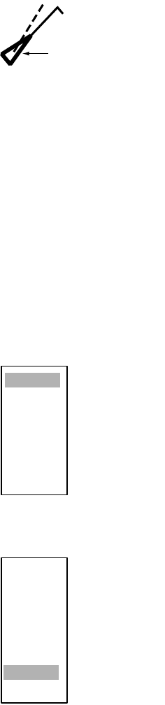
4. AIS OPERATION
4-8
4.12 CPA and TCPA Alarm
When the predicted CPA of any ARP/AIS target becomes smaller than a preset CPA alarm range
or its predicted TCPA less than a preset TCPA alarm limit, an audio alarm sounds and the symbol
of the offending AIS target changes to the dangerous target symbol.
Dangerous target symbol
You may silence the audio alarm with the CANCEL/HL OFF key. The flashing of the symbol con-
tinues until you intentionally terminate tracking of the target. The ARP continuously monitors the
predicted range at the Closest Point of Approach (CPA) and predicted time to CPA (TCPA) of
each AIS target.
This feature helps alert you to targets which may be on a collision course with own ship. However,
it is important that GAIN, SEA, RAIN and other radar controls are properly adjusted.
1. Press the MENU key to open the menu.
2. Choose Target and then press the ENTER key.
3. Choose CPA and then press the ENTER key.
4. Choose appropriate time and then press the ENTER key.
5. Choose TCPA and then press the ENTER key.
6. Choose appropriate TCPA and then press the ENTER key.
7. Press the MENU key to close the menu.
Triangle is thicker
than that of active
target
Off
0.5nm
1nm
2nm
3nm
5nm
6nm
30sec
1min
2min
3min
4min
5min
6min
12min

4. AIS OPERATION
4-9
4.13 Proximity Alarm
The proximity alerts you by audio and visual alarms when an ARP/AIS target is within the range
you specify.
1. Press the MENU key to open the menu.
2. Choose Target and then press the ENTER key.
3. Choose Proximity Alarm and then press the ENTER key.
4. Choose appropriate range and then press the ENTER key.
5. Press the MENU key to close the menu.
4.14 Lost Target
When the system detects a lost target, the target symbol becomes a diamond and tracking is dis-
continued after one minute.
Lost target mark
Canceling a lost target
Place the cursor on the target and then press the CANCEL/HL OFF key.
Off
0.5nm
1nm
2nm
3nm
5nm
6nm
12nm
24nm

4. AIS OPERATION
4-10
4.15 Symbol Color
You may choose the ARP/AIS symbol color from among Green, Red, Blue, White or Black.
1. Press the MENU key to open the menu.
2. Choose ARP and then press the ENTER key.
3. Choose Symbol Color and then press the ENTER key.
4. Choose appropriate color and then press the ENTER key.
5. Press the MENU key to close the menu.
Green
Red
Blue
White
Black
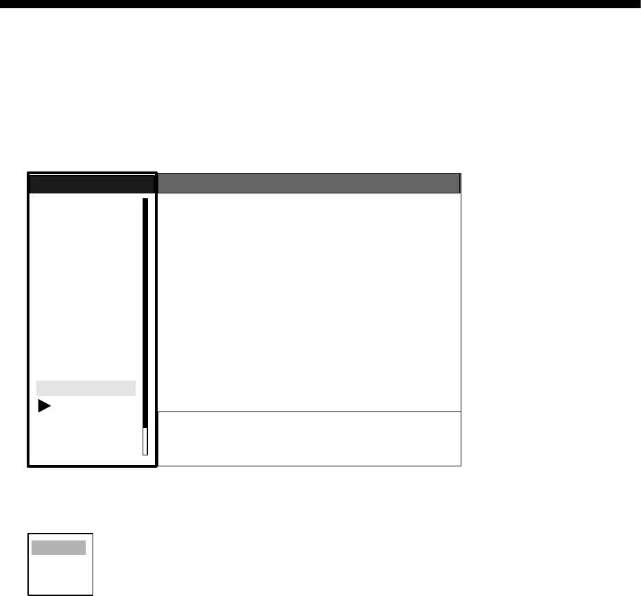
5-1
5. GPS OPERATION
With connection of a FURUNO GPS navigator, you may set up the GPS navigator from this radar.
5.1 Navigator Type
1. Press the MENU key to show the menu.
2. Choose GPS and then press the ENTER key.
GPS menu
3. Choose Type and then press the ENTER key.
4. Choose type of navigator connected to this radar and then press the ENTER key.
5. Press the MENU key to close the menu.
GPS
Brill/Color
Echo
Mark
Target Trails
Custom 1
Display
Custom 2
Custom 3
Target
ARP
AIS
Manual Tune
Menu
Menu
GPS
GPS
System
Type : WAAS
Datum : WGS-84
Datum Number : 001
WAAS : Auto
WAAS Number : 120
GPS Self Test
Satellite Monitor
Type 16 Message
Forward Offset : 0
Right Offset : 0
Cold Start
S/T / W/X: Select
[ENTER]: Enter [CANCEL/HL OFF]: Back
[MENU]: Exit
GPS
WAAS
DGPS

5. GPS OPERATION
5-2
5.2 Datum
Choose the datum type which matches the paper nautical charts you are using. Choose WGS-84
if the radar is interfaced to an AIS Transponder.
1. Press the MENU key to show the menu.
2. Choose GPS and then press the ENTER key.
3. Choose Datum and then press the ENTER key.
4. Choose appropriate datum type and then press the ENTER key. For Other, do steps 5 and 6.
For other choices, go to step 7.
5. Choose Datum Number and then press the ENTER key.
6. Use the trackball to choose datum number and then press the ENTER key.
7. Press the MENU key to close the menu.
5.3 WAAS Setup
Choose either automatic or manual WAAS satellite tracking. For manual tracking choose the
WAAS satellite to use.
1. Press the MENU key to show the menu.
2. Choose GPS and then press the ENTER key.
3. Choose WAAS and then press the ENTER key.
4. Choose Auto or Manual as appropriate and then press the ENTER key. For Manual, do steps
5 and 6. For Auto, go to step 7.
5. Choose WAAS Number and then press the ENTER key.
6. Use the trackball to choose appropriate WAAS satellite number and then press the ENTER key.
7. Press the MENU key to close the menu.
WGS-84
Tokyo
Other
001
Auto
Manual
120
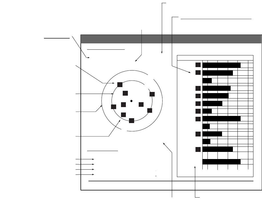
5. GPS OPERATION
5-3
5.4 Satellite Monitor
The Satellite Monitor provides comprehensive information about GPS and WAAS satellites. For
more detailed information, see your GPS navigator’s owner’s manual.
1. Press the MENU key to show the menu.
2. Choose GPS and then press the ENTER key.
3. Choose Satellite Monitor and then press the ENTER key.
Satellite monitor
To close only the satellite monitor display, press the ENTER key.
D3D DOP
1.5
85m
Satellite Monitor
DGPS Status
Station Health
DGPS Data
Signal Strength
Signal SNR
OK
OK
10dB
11dB
13
Altitude
01GPS
WAAS
12
24
16
SNRSatellite
30 40 50
122
01
31
18
19
06
07
09
08
13
Satellite Monitor
16
13
01 06
19
18
09
07 08
31
12
24
Bearing
display
DOP (Dilution of Precision, 0-99.0)
SNR of tracked GPS satellites
Satellites whose SNR is above
40 are used to fix position.
GPS mode
2D, 3D, D2D
D3D, W2D
W3D, DOP
GPS satellite
no.
WAAS
satellite
Satellites in ring
have elevation
angle of 5°
Satellites in ring
have elevation
angle of 45°
O
K or NG (No Good) displayed
O
K or NG (No Good) displayed
0-99 db, higher the better
0-99 db, higher the better
Satellite
altitude
WAAS satellite
W
N
[MENU]: Close MENU [ENTER]: Close this window
5. GPS OPERATION
5-4
5.5 Type 16 Message
The type 16 message provides weather information. It is transmitted by the Japan Maritime Safety
Agency, thus you must be within the transmitting range of a japanese DGPS reference station to
receive this type of message.
You may display this type of message as follows:
1. Press the MENU key to show the menu.
2. Choose GPS and then press the ENTER key.
3. Choose Type 16 Message and then press the ENTER key. (If no messages are present you
cannot choose this menu item.)
Type 16 message
Weather messages from as many as six DPGS reference stations are shown and the latest is at
the top.The oldest message is erased when a new message arrives.
To close only the message board, press the ENTER key.
Type 16 Message
Type 16 Message
Point Name Time Wind Pressure Wave
Direction/Speed
Murotasaki
Kobe
Osakako
Oseki
Tomgashima
Shinomisaki
13:25
13:55
13:45
13:15
13:50
13:55
13:35
13:05
13:30
13:00
ENE
NE
NW
N
N
NW
SSW
S
NW
W
5m
10m
5m
10m
5m
10m
5m
10m
5m
10m
1015hPa
1016hPa
1015hPa
1017hPa
1017hPa
1017hPa
1013hPa
1015hPa
1015hPa
1016hPa
10m
13m
11m
10m
9m
10m
8m
9m
5m
10m
13:30
13:00 NW
W5m
10m 1015hPa
1016hPa 5m
10m
[MENU]: Close MENU [ENTER]: Close this window
N
ame of DGPS
r
eference station
Time
Wind direction
and speed
(16 compass pts.)
Atmospheric
pressure (0-9999 hPa)
Wave heig
ht
(0-99 m)
5. GPS OPERATION
5-5
5.6 GPS Sensor Installation Position Offset
The installation position of the GPS sensor antenna and the radar antenna must be the same in
order to get accurate position information on the radar. If they are different, measure the distance
between the GPS sensor antenna and the radar antenna, in the bow/stern and/or port/starboard
direction, and enter those distances in the radar as follows:
1. Press the MENU key to show the menu.
2. Choose GPS and then press the ENTER key.
3. Choose Forward Offset (bow or stern offset) or Right Offset (port or starboard offset) as appro-
priate and then press the ENTER key.
4. Use the trackball to set value and then press the ENTER key.
+ value: Bow direction, port direction
- value: Stern direction, starboard direction
5. Press the MENU key to close the menu.
+ 0m
(-999m-+999m)

5. GPS OPERATION
5-6
5.7 Cold Start
A cold start may be necessary in the following conditions:
• If the GPS receiver has been powered off for a long period of time.
• The vessel has far away from the previous fixing position (e.g., more than 500 km).
• Other reason that prevents the receiver from finding its position within five minutes after power
on.
To perform a cold start, do the following:
1. Press the MENU key to show the menu.
2. Choose GPS and then press the ENTER key.
3. Choose Cold Start and then press the ENTER key.
4. Choose Yes and then press the ENTER key.
5. Press the MENU key to close the menu.
Confirm
Is it all right?
Yes
No
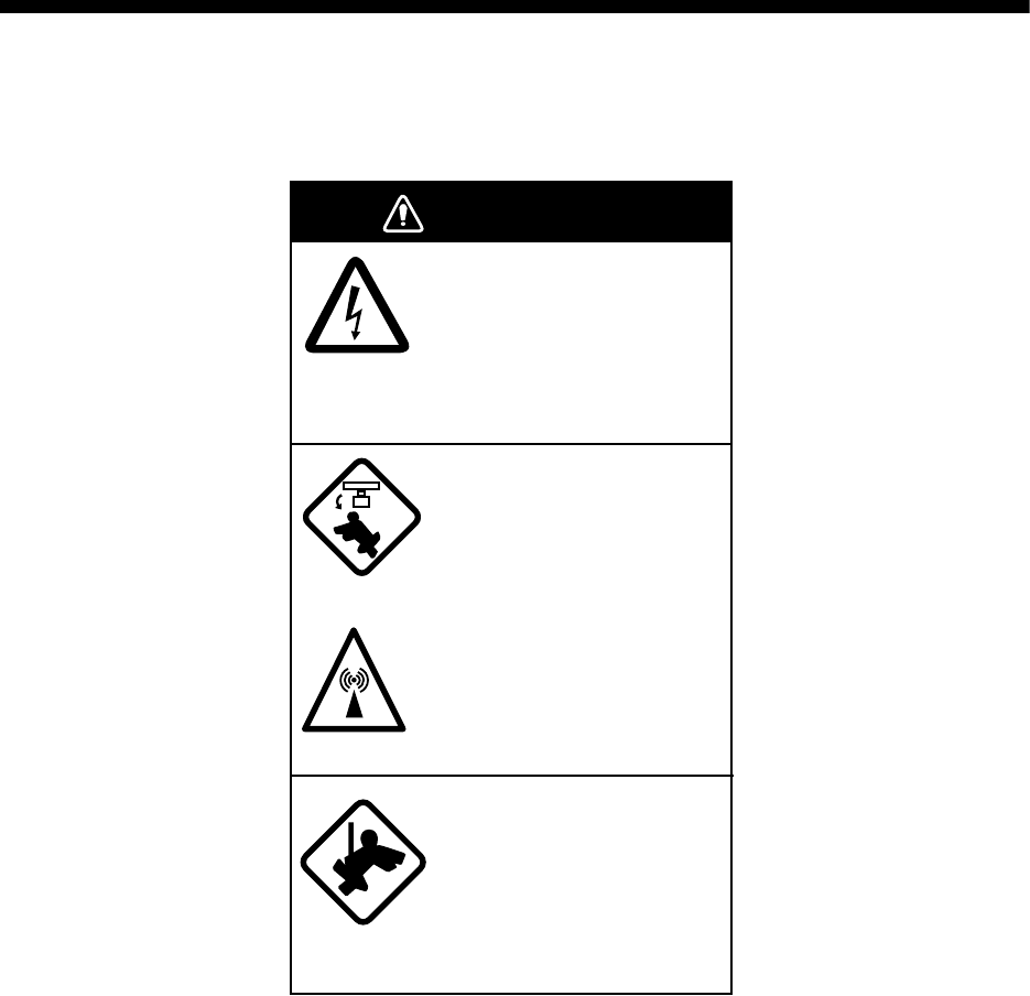
6-1
6. MAINTENANCE &
TROUBLESHOOTING
This chapter provides the necessary procedures for maintenance and troubleshooting. Follow the
recommend procedures to keep your radar in good working order.
WARNING
Do not open the equipment.
Hazardous voltage which can
cause electrical shock exists
inside the equipment. Only
qualified personnel should
work inside the equipment.
Turn off the radar power
switch before servicing the
antenna unit. Post a warn-
ing sign near the switch
indicating it should not be
turned on while the antenna
unit is being serviced.
Prevent the potential risk of
being struck by the rotating
antenna and exposure to
RF radiation hazard.
Wear a safety belt and hard
hat when working on the
antenna unit.
Serious injury or death can
result if someone falls from
the radar antenna mast.

6. MAINTENANCE & TROUBLESHOOTING
6-2
6.1 Preventive Maintenance
Regular maintenance is important for optimum performance. A maintenance program should be
established and should at least include the items shown in the table below.
Maintenance
Interval Item Check point Remedy
When
necessary
LCD The LCD will, in time,
accumulate a coating of
dust which tends to dim
the picture. Wipe LCD
lightly with soft cloth to
remove dust.
Wipe the LCD carefully to prevent
scratching, using tissue paper and an
LCD cleaner. To remove dirt or salt
deposits, use an LCD cleaner, wiping
slowly with tissue paper so as to dissolve
the dirt or salt. Change paper frequently
so the salt or dirt will not scratch the
LCD. Do not use solvents such as
thinner, acetone or benzene for
cleaning. They may remove paint and
markings.
3 to 6
months
Ground
terminal on dis-
play unit
Check for tight connec-
tion and rust.
Tighten or replace as necessary.
DIsplay unit
connectors
Check for tight connec-
tion.
Tighten if loosened.
Exposed nuts
and bolts on
antenna unit
Check for corroded or
loosened bolts.
Clean and repaint as necessary. Sealing
compound may be used in place of paint.
Antenna
radiator
Check for dirt and cracks
on radiator
surface.f
Clean radiator surface with freshwater-
moistened cloth. Do not use plastic sol-
vents for cleaning.
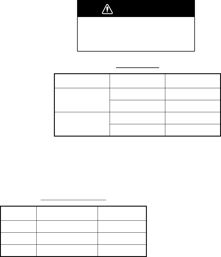
6. MAINTENANCE & TROUBLESHOOTING
6-3
6.2 Replacement of Fuses
The fuse on the power cable protects the equipment from reverse polarity of the ship's mains and
equipment fault. If the fuse blows, find out the cause before replacing it. Use the correct fuse.
Using the wrong fuse will damage the equipment and void the warranty.
6.3 Replacing the Magnetron
When the magnetron has expired, distant targets cannot be seen on the display. When you feel
that long range performance has decreased, contact a FURUNO agent or dealer about replace-
ment.
Unit and fuses
Unit Power supply Fuse
DIsplay unit 12 V 15 A
24 V 10 A
Power supply unit
(for FR-8252)
12 V 15 A
24 V 10 A
Model and magnetron
Model Magnetron type Code No.
FR-8062 MAF1422B 000-146-871
FR-8122 MAF1425B 000-146-872
FR-8252 MAF1458B 000-140-344
WARNING
Use the proper fuse.
Use of a wrong fuse can result in damage
to the equipment or cause fire.
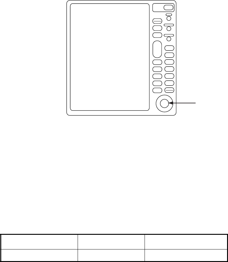
6. MAINTENANCE & TROUBLESHOOTING
6-4
6.4 Trackball Maintenance
If the cursor skips or moves abnormally, you may need to clean the Trackball.
DIsplay unit
1. Turn the retainer ring counterclockwise 45° to unlock it.
2. Remove the retainer ring and ball.
3. Clean the ball with a soft lint-free cloth, and then blow carefully into the ball-cage to dislodge
dust and lint.
4. Look for a build-up of dirt on the metal rollers. If dirty, clean the rollers with a cotton swab moist-
ened lightly with isopropyl-rubbing alcohol.
5. Make sure that fluff from the swab is not left on the rollers.
6. Replace the ball and retainer ring. Be sure the retainer ring is not inserted reversely.
Trackball maintenance parts are available as below.
Part Type No. Code No.
Retainer ring and ball MU3721 000-144-645
ENTER
TARGET
ALARM
CANCEL
HL OFF
TLLMENU
EBL
ZOOM OFF
CENTER
TRAILS
VRM
F1
F2
PUSH AUTO/MAN
PUSH AUTO/MAN
PUSH AUTO/MAN
STBY
TX
MODE
CUSTOM
+
RANGE
-
GAIN
SEA
RAIN
POWER
BRILL
Trackball

6. MAINTENANCE & TROUBLESHOOTING
6-5
6.5 Simple Troubleshooting
This section provides simple troubleshooting procedures which the user can follow to restore
normal operation. If you cannot restore normal operation do not attempt to check inside the unit.
Any trouble should be referred to a qualified technician.
Simple troubleshooting
If... But... Then...
you cannot turn on
the power
• Check for blown fuse.
• Check that the power connector is firmly
fastened.
• Check for corrosion on the power cable
connector.
• Check for damaged power cable.
• Check battery for proper voltage output (10.8-
31.2 V).
there is no response
when a key is
pressed
Turn off and on the power. If there still is no
response the key may be faulty. Contact your
dealer for advice.
if the power is on and
you operated the
STBY/TX key to
transmit
nothing appears on the
display
Check that the antenna cable is firmly fastened.
marks and legends
appears
no echo appears Check that the antenna cable is firmly fastened.
tuning is properly
adjusted
sensitivity is poor The magnetron may need to be replaced.
Contact your dealer.
the range is changed but radar picture does not
change
• Try to hit the RANGE key again.
• Turn the display unit off and on.
there is poor discrim-
ination in range
Adjust the SEA control.
the true motion
presentation is not
working properly
• Reselect the true motion mode.
• Check if heading and speed are input.
the range rings are
not displayed
Check that the setting of Range Rings Brill in the
Brill/Color sub menu is set to other than Off.

6. MAINTENANCE & TROUBLESHOOTING
6-6
6.6 Advanced-level Troubleshooting
This paragraph describes how to cure hardware and software troubles which should be carried
out by qualified service personnel.
Note: This radar equipment contains complex modules in which fault diagnosis and repair down
to component level are not practicable by users.
Advanced-level troubleshooting
Problem Probable cause or
check points Remedy
Power turned on but
radar does not work
1) Blown fuse.
2) Mains voltage/polarity
3) Power supply board
1) Replace blown fuse.
2) Correct wiring and input voltage.
3) Replace power supply board.
Brilliance adjusted
but no picture
1) SPU Board 1) Replace SPU board.
Antenna not rotating 1) Antenna drive mechanism 1) Replace antenna drive mechanism.
Data and marks not
displayed in Transmit
status
1) SPU board 1) Replace SPU board.
Adjust GAIN with
SEA set at minimum.
Marks and indications
appear but no noise
or echo
1) IF amplifier
2) Signal cable between
antenna and processor unit
3. Video amplifier board
1) Replace IF amplifier.
2) Check continuity and isolation of coaxial
cable.
Note: Disconnect the plug and lugs at both
ends of coaxial cable before checking it (by
ohmmeter).
3) Check coax line for secure connection. If
connection is good, replace SPU board.
Marks, indications
and noise appear but
no echo (Transmis-
sion leak repre-
senting own ship
position is absent)
1) Tx fuse
2) Magnetron
3) Modulator board
4) SPU board
1) If fuse has blown, replace it. If it blows
again, the modulator or associated circuit
may be defective.
2) Check magnetron current.
3) Replace modulator board.
4) Replace SPU board.
Picture not updated
or picture freeze-up
1) Bearing signal generator
2) SPU board
3) Video freeze-up
1) Check that signal cables are fastened
securely.
2) Replace SPU board.
3) Turn the radar off and on.
Radar is properly
tuned but sensitivity is
poor
1) Deteriorated magnetron
2) Detuned MIC
3) Dirt on radiator face
4) 2nd trace echo rejector is
ON.
1) With the radar transmitting on 48 nm
range, check magnetron current. If cur-
rent is below normal, magnetron may be
defective. Replace the magnetron.
2) Check MIC detecting current. If it is below
normal value, MIC may have become
detuned. MIC must be tuned
3) Clean radiator.
4) Turn off the 2nd trace echo rejector, on
the Echo menu.

6. MAINTENANCE & TROUBLESHOOTING
6-7
Range changed but
radar picture does not
change
1) Defective range key
2) SPU board
3) Video freeze-up
1) Try to operate the RANGE key. If unsuc-
cessful, replacement of the keypad may
be necessary.
2) Replace SPU board.
3) Turn radar off and on.
Interference rejector
is not working (inter-
ference rejection
level not displayed)
1) SPU Board 1) Replace SPU Board.
Echo stretch is not
working (Neither
ES1, ES2 or ES3 is
displayed)
1) SPU Board 1) SPU Board
Range rings are not
displayed
1) Adjust their brilliance on the
Brill/Color menu.
2) SPU Board
1) Replace associated circuit board if unsuc-
cessful.
2) Replace SPU Board.
Poor discrimination in
range
Sea clutter control not func-
tioning properly
Improper adjustment of SEA control.
True motion presen-
tation not working
properly
1) Poor contact of MODE key.
2) TM display accurate 1) Try to press the key a little harder.
2) Make sure that speed and compass
inputs are accurate.
Target not tracked
correctly
Poor definition of targets in sea
clutter
Adjust SEA and RAIN controls.
Advanced-level troubleshooting
Problem Probable cause or
check points Remedy
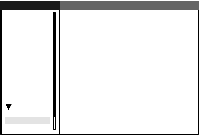
6. MAINTENANCE & TROUBLESHOOTING
6-8
6.7 System Test
The diagnostic test checks the system for proper operation.
1. Press the MENU key to open the menu.
2. Use the trackball to choose Factory from the System menu and then press the ENTER key.
Factory menu
GPS
Brill/Color
Echo
Mark
Target Trails
Custom 1
Display
Custom 2
Custom 3
Target
ARP
AIS
Manual Tune
System
Initial
Factory
Installation
Test
LCD Pattern
Memory Clear
Menu
Menu
Factory
Factory
S/T / W/X: Select
[ENTER]: Enter [CANCEL/HL OFF]: Back
[MENU]: Exit
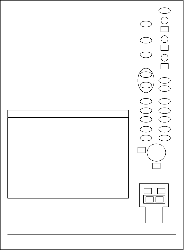
6. MAINTENANCE & TROUBLESHOOTING
6-9
3. Use the trackball to choose Test and then press the ENTER key.
DIagnostics screen
• At the top of the screen the results of system checks are displayed. OK or NG (No Good)
is shown as the result for the check of ROM, RAM, data ports NMEA1 and NMEA2
(blank if no data is input) and RS-232C. For any NG contact your dealer for advice.
PROGRAM NUMBER shows program number and program version number.
• Heading and bearing signals are checked for proper input and the result displayed as
OK or NG. Tune and indicator voltages, antenna rotation speed, antenna motor voltage,
echo level and trigger frequency are measured and shown. TOTAL ON TIME and
TOTAL TX TIME show the total number of hours the radar has been powered and trans-
mitted, respectively.
• The INPUT NMEA window shows all the NMEA sentences being input to this radar.
• If the optional ARP-11 is connected, its program number and test results are shown
below the INPUT NMEA window.
INPUT NMEA
ROM : OK
RAM : OK
NMEA1 : OK
NMEA2 : OK
RS-232C : OK
PROGRAM NUMBER : 0317101-XX.XX
HEADING : OK
BEARING : OK
TUNE VOLTAGE : 10.1 V
INDICATOR VOLTAGE : 4.2 V
ANTENNA ROTATION : 48.1 rmp
MOTOR VOLTAGE : 23.4 V
ECHO LEVEL : -40 dBm
TRIGGER FREQUENCY : 3000 Hz
TOTAL ON TIME : 123456.7 H
TOTAL TX TIME : 987654.3 H
Input NMEA data sentences appear here.
ARP-11 PROGRAM NUMBER: 035-1515-XX.XX
ARP-11 : OK
[MENU] x 3 : Exit
<REMOTE CONTROLLER>
000
000
000
000
000

6. MAINTENANCE & TROUBLESHOOTING
6-10
• At the right side of the display there are squares, circles and ovals, and they are for
checking the controls of the display unit and remote controller. Press each key one by
one. The key’s on location “lights” (color depends on color scheme in use) if the key is
functioning normally and extinguishes when the key is released. For the GAIN, SEA and
and RAIN controls the three-digits below each control changes according to control
position, and the range is 0-100. The three digits below the trackball show the trackball’s
on-screen X-Y position and the range of display is 0-255.
4. Press the MENU key three times on the display unit or remote controller to esape from the test.
6.8 LCD Test
The LCD pattern test checks the LCD for proper display of colors.
1. Press the MENU key to open the menu.
2. Use the trackball to choose Factory from the System menu and then press the ENTER key.
3. Use the trackball to choose LCD Pattern and then press the ENTER key.
The screen is initially all white. Hit the MENU key to display the test pattern for black, red, blue
and green colors.
LCD test screens
4. Press the MENU key to close the menu.
WHITE BLACK RED GREEN BLUE
MENU
key
MENU
key

6. MAINTENANCE & TROUBLESHOOTING
6-11
6.9 GPS Test
The FURUNO GPS receiver interfaced with this radar can be checked for proper operation as fol-
lows:
1. Press the MENU key to open the menu.
2. Use the trackball to choose GPS and then press the ENTER key.
3. Use the trackball to choose GPS Self Test and then press the ENTER key. The program no.
and results of the test are shown, as OK or NG (No Good). For NG, check the GPS receiver
GPS self test results
4. Press the MENU key to close the menu.
GPS Self Test
GPS Self Test
Program No. : 48502380XX
Result : OK
XX = Program version no.

6. MAINTENANCE & TROUBLESHOOTING
6-12
6.10 Clearing the Memory
You may wish to clear the memory to restore all default settings, to start afresh.
1. Press the MENU key to open the menu.
2. Use the trackball to choose Factory from the System menu and then press the ENTER key.
3. Use the trackball to choose Memory Clear and then press the ENTER key. You are asked if you
are sure to clear the memory.
4.Choose Yes and then press the ENTER key to clear the memory.
5. When the memory is cleared a long buzzer sounds.
Confirm
Is it all right?
Yes
No

FURUNO
FR-8xx2 Series
SP - 1 E354S01A
SPECIFICATIONS OF MARINE RADAR
FR-8062/FR-8122/FR-8252
1. GENERAL
1.1 Range, Pulse length, (PL) & Pulse repetition rate (PRR)
Range (nm) Pulse length (µs) PRR (Hz approx.)
0.125 to 1.5 0.08 2100
1.5 to 3 0.3 1200
3 to 96 0.8 600
1.2 Maximum Range 96 nm (all models)
1.3 Range Resolution 20 m
1.4 Bearing Resolution 1.9° (4 ft), 1.2° (6 ft)
1.5 Minimum Range 21 m
1.6 Bearing Accuracy ±1.0°
1.7 Range, Range Ring Accuracy 1.0% of range or 8 m, whichever is the greater
2. ANTENNA UNIT
2.1 XN-12A (4 ft)
2.1.1 Radiator Slotted array
2.1.2 Polarization Horizontal
2.1.3 Antenna Rotation 24 rpm, 36 rpm, 48 rpm, range dependent rpm. (24 rpm motor
fixed at 24 rpm.)
2.1.4 Radiator Length 125.5 cm
2.1.5 Horizontal Beamwidth 1.9°
2.1.6 Vertical Beamwidth 2.2°
2.1.7 Sidelobe Attenuation -24 dB or less (within ±10° of main-lobe)
-30 dB or less (±10° of main-lobe or more)
2.2 XN-13A (6 ft)
2.2.1 Radiator Slotted array
2.2.2 Polarization Horizontal
2.2.3 Antenna Rotation 24 rpm, 36 rpm, 48 rpm, range dependent rpm. (24 rpm motor
fixed at 24 rpm.)
2.2.4 Radiator Length 180 cm
2.2.5 Horizontal Beamwidth 1.35°
2.2.6 Vertical Beamwidth 2.2°
2.2.7 Sidelobe Attenuation -28 dB or less (within ±10° of main-lobe)
-35 dB or less (±10° of main-lobe or more)
3. RF TRANSCEIVER
3.1 Frequency and Modulation 9410 MHz ±30MHz (X band), P0N
3.2 Peak Output Power FR-8062: 6 kW, FR-8112: 12 kW, FR-8052: 25 kW

FURUNO
FR-8xx2 Series
SP - 2 E354S01A
3.3 Intermediate Frequency 60 MHz
3.4 Tuning Automatic or manual
3.5 Pulse length, PL, PRF and range
Pulse length Short Medium Long
PL (µs) 0.08 0.3 0.8
PRF (Hz) 2100 1200 800
Range scale (nm) 0.125, 0,25, 0,5, 0,75, 1,0 1.5, 2, 3 2, 3, 4, 6, 8, 12, 16, 24, 36, 48, 64,
72, 96
3.6 Noise figure 6 dB (typical)
4. DISPLAY UNIT
4.1 Display 12.1-inch rectangular TFT color LCD, 600 x 800 dots,
Effective radar display 298 dots
4.2 Range, Range Ring Interval (RI), Number of Rings
Range 0.125 0.25 0.5 0.75 1 2 3 4 6 8 12 16 24 36 48 6
47
29
6
Ring
Interval 0.025 0.05 0.1 0.25 0.25 0.5 0.5 1 1 2 2 4 4 6 8 1
61
21
6
No. of
rings 5 5 5 3 4 4 6 4 6 4 6 4 6 6 6 4 6 6
4.3 Markers Heading Line, Bearing Scale, Range Rings, Variable Range
Marker (VRM), Electronic Bearing Line (EBL), Target Alarm
Zone, Waypoint Mark (navigation input required), Zoom Win-
dow
4.4 Alphanumeric Indications Range, Range Ring Interval, Interference Rejection (IR), Vari-
able Range Marker (VRM), Electronic Bearing Line (EBL),
Stand-by (ST-BY), Echo Averaging (EAV), TX Pulse width,
Guard Alarm (G(IN), G(OUT)), Echo Stretch (ES), Range and
Bearing to Cursor or Cursor Position, Echo Trail Reference,
Echo Trail Time, Nav Data (Position, Speed, Course, etc.),
ARP/AIS Target Data
5. POWER SUPPLY
5.1 Rated Voltage/Current FR-8062 - 12-24 VDC: 3.2 A (24 V, no wind)
FR-8122 - 12-24 VDC: 3.8 A (24 V, no wind)
FR-8252 - 12-24 VDC: 5.0 A (24 V, no wind)
5.2 Rectifier (option) 100-115/220-230 VAC, 1 phase, 50/60 Hz
6. ENVIRONMENTAL CONDITIONS
6.1 Ambient Temperature Antenna Unit: -25°C to +70°C
Display Unit: -15°C to +55°C
Remote Controller: +5°C to +45°C
Power Supply Unit: -15°C to +55°C
6.2 Relative Humidity 93% or less at +40°C
FURUNO
FR-8xx2 Series
SP - 3 E354S01A
6.3 Waterproofing Antenna Unit: IPX6
Display Unit: IPX5
Remote Controller, Power Supply Unit: IPX0
6.4 Vibration IEC 60945-4th - 2Hz to 5 Hz and up to 13.2 Hz with a deviation of ±1 mm
±10% (7 m/s2 maximum acceleration at 13.2 Hz);
- above 13.2 Hz and up to 100 Hz with a constant maximum
acceleration of 7 m/s2 .
7. COATING COLOR
7.1 Display Unit N3.0
7.2 Antenna Unit N9.5
FURUNO
FR-8xx2 Series
SP - 4 E354S01A
This page intentionally left blank.

IN-1
INDEX
A
Advanced-level troubleshooting, 6-6
AISactivating targets, 4-2
activating, deactivating, 4-1
controls for, 4-1
CPA, TCPA alarm, 4-8
display on/off, 4-2
display range, 4-4
display sector, 4-5
lost target, 4-9
number of targets, 4-5
proximity alarm, 4-9
sorting targets, 4-4
symbol color, 4-10
target data, 4-3
target past positions (history display), 4-7
vector, 4-6
Alarm message, 1-44
Antenna speed, 1-42
ARP
acquiring targets, 3-3
activating, deactivating, 3-2
controls for, 3-2
CPA, TCPA alarm, 3-8
lost target, 3-9
past target positions, 3-6
proximity alarm, 3-9
symbol color, 3-10
terminating tracking of target, 3-4
usage precautions, 3-1
vector, 3-5
B
Background color, 1-38
C
CANCEL/HL OFF key, 1-33
Characteristics curve, 1-42
Color schemes, 1-38
Control description, 1-2
Controls, 1-1
Course-up mode, 1-9
Cursor, 1-15
CUSTOM key, 1-34
Custom setup
description, 1-34
setting, 1-35
D
Depth unit, 1-47
Dynamic range, 1-41
E
EBL
measuring bearing by, 1-19
reference, 1-19
EBL key, 1-20
Echo area, 1-45
Echo averaging, 1-27
Echo stretch, 1-26
F
F1, F2 key, 1-36
False echoes, 2-3
Function keys, 1-36
Fuse replacement, 6-3
G
GAIN control
adjustment method, 1-11
automatic adjustment, 1-11
manual adjustment, 1-12
GPS
cold start, 5-6
datum, 5-2
navigator type, 5-1
satellite monitor, 5-3
sensor installation offset, 5-5
test, 6-11
type 16 message, 5-4
WAAS, 5-2
GPS test, 6-11
H
Heading line, 1-33
Heading marker, 1-33
Head-up mode, 1-8
Head-up true bearing mode, 1-9
I
Indications, 1-5
Initial menu, 1-46
Interference rejector, 1-16
K
Key beep, 1-46
M
Magnetron replacement, 6-3
Maintenance
fuse replacement, 6-3
magnetron replacement, 6-3
preventive, 6-2
trackball, 6-4
Memory clear, 6-12
Menu, 1-6
MENU key, 1-6
MODE key, 1-8
Multiple echoes, 2-3
INDEX
IN-2
N
Navigation data
at screen bottom, 1-40
standby, 1-39
Noise rejector, 1-36
North-up mode, 1-9
O
OFF CENTER key, 1-24
Offcentering the display, 1-24
Origin mark, 1-33
P
Parallel index lines
mode, 1-32
turning on/off, 1-31
POWER/BRILL key, 1-4, 1-6
Presentation mode
course-up, 1-9
heading, 1-8
north-up, 1-9
true bearing mode, 1-9
true motion, 1-10
Preventive maintenance, 6-2
Pulse length, 1-11
Q
Quick start, 1-4
R
RACON, 2-6
RAIN control
adjustment method, 1-13
automatic adjustment, 1-14
manual adjustment, 1-14
Range and bearing between two targets, 1-20
RANGE key, 1-10
Range measurement, 1-17
Range preset, 1-47
Range ring brilliance, 1-17
Range unit, 1-46
S
SART, 2-5
SEA control
adjustment method, 1-12
automatic adjustment, 1-12
manual adjustment, 1-13
Second-trace echoes, 1-37
Ship speed unit, 1-47
Sidelobe echoes, 2-3
STBY/TX key, 1-4
System configuration, 1-ix
System test, 6-8
T
Target alarm
acknowledging, 1-22
alarm type, 1-22
sensitivity, 1-23
setting, 1-21
TARGET ALARM key, 1-21
Target trails
color, 1-29
gradation, 1-29
level, 1-29
long trails, 1-31
mode, 1-28
own ship trail, 1-30
restarting, 1-31
starting, 1-28
stopping, 1-28
thin trails, 1-30
trail copy, 1-30
Temperature unit, 1-47
Tests
GPS test, 6-11
LCD test, 6-10
system, 6-8
TLL key, 1-32
Trackball maintenance, 6-4
TRAILS key, 1-28
Troubleshooting
advanced level, 6-6
simple, 6-5
True motion mode, 1-10
Tuning, 1-7
V
Virtual image, 2-4
VRM
measuring range by, 1-17
unit of range measurement, 1-18
VRM key, 1-17
W
Watchman, 1-37
Waypoint mark, 1-43
Wind direction, 1-47
Wind speed unit, 1-47
Z
ZOOM key, 1-25