Furuno USA 9ZWRTR086A Marine Radar User Manual
Furuno USA Inc Marine Radar
UserManual.wiki
>
Furuno USA
>
9ZWRTR086A User Manual
>
op manual
Contents
1.
op manual
2.
install manual part 1
3.
install manual part 2
op manual
Navigation menu
Upload a User Manual
Namespaces
Wiki Guide
HTML
PDF
Info
Views
User Manual
Discussion / Help
Navigation
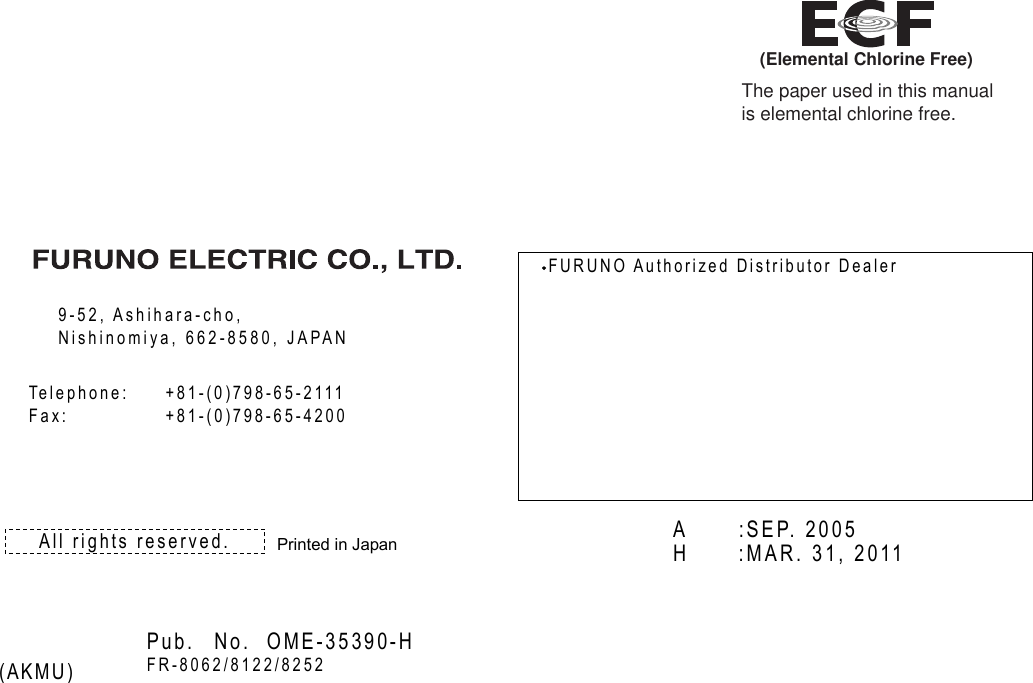
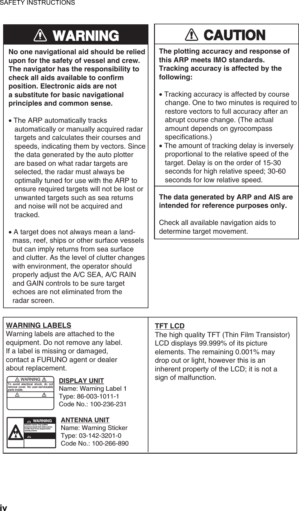
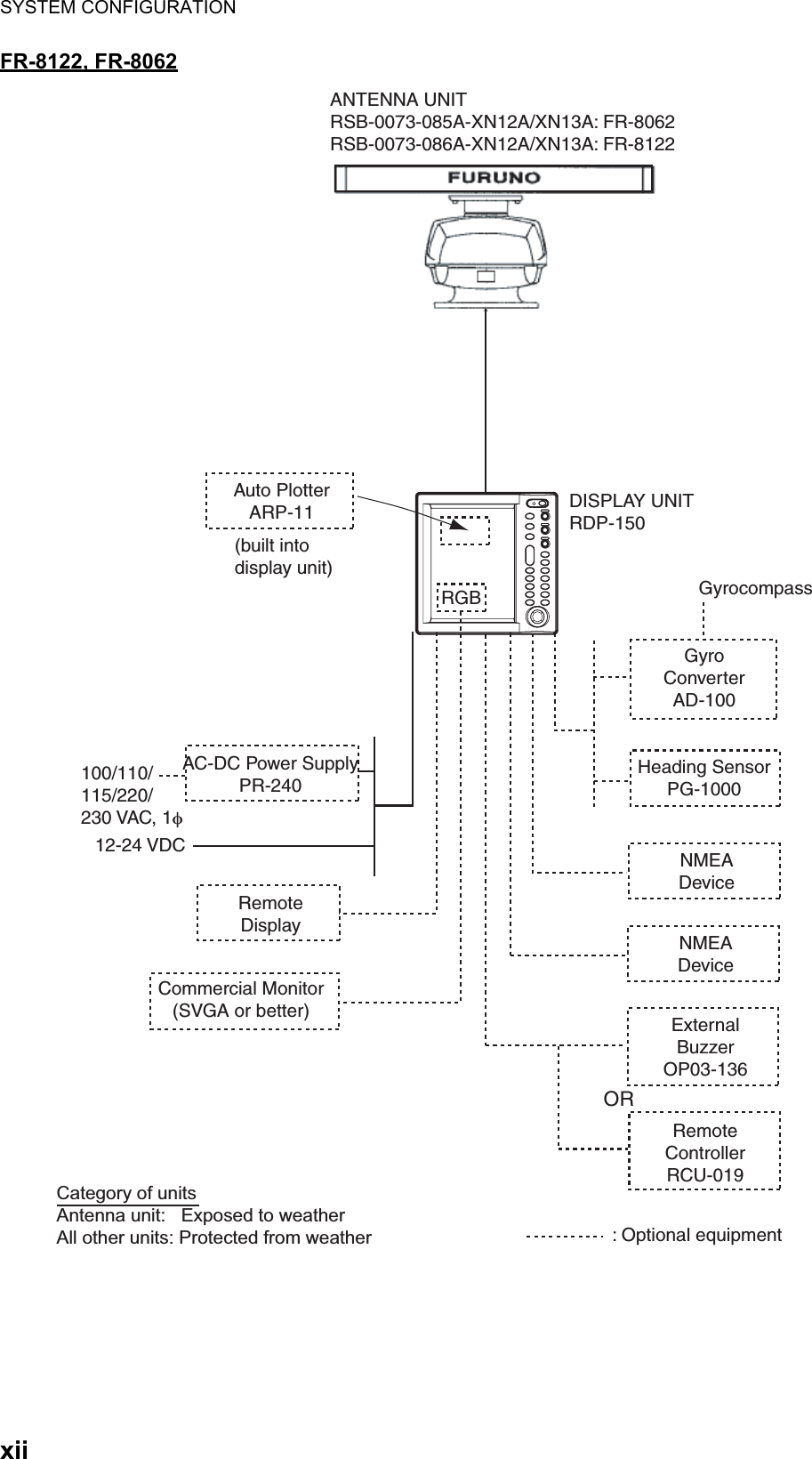
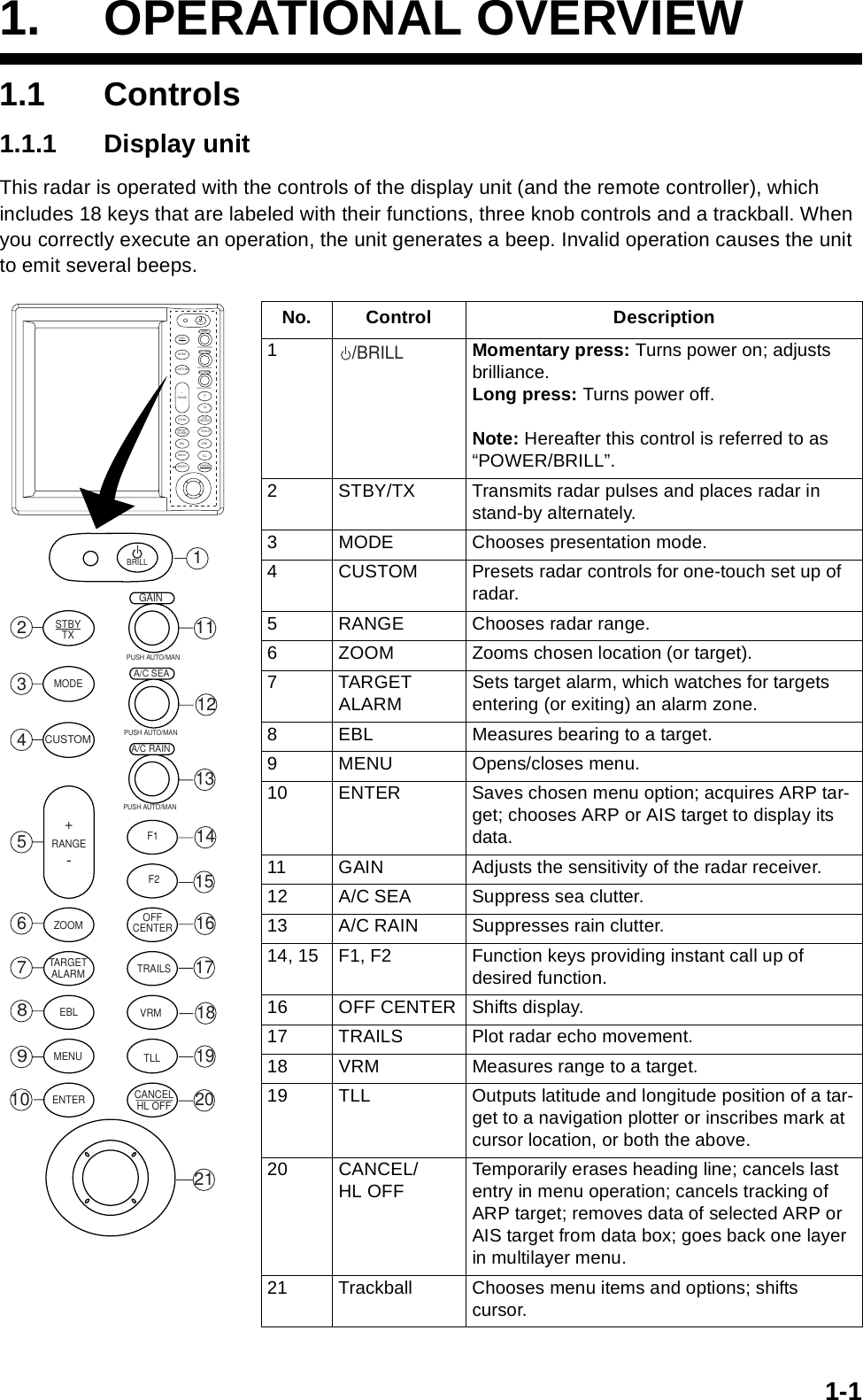
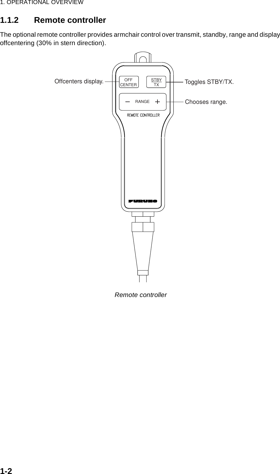
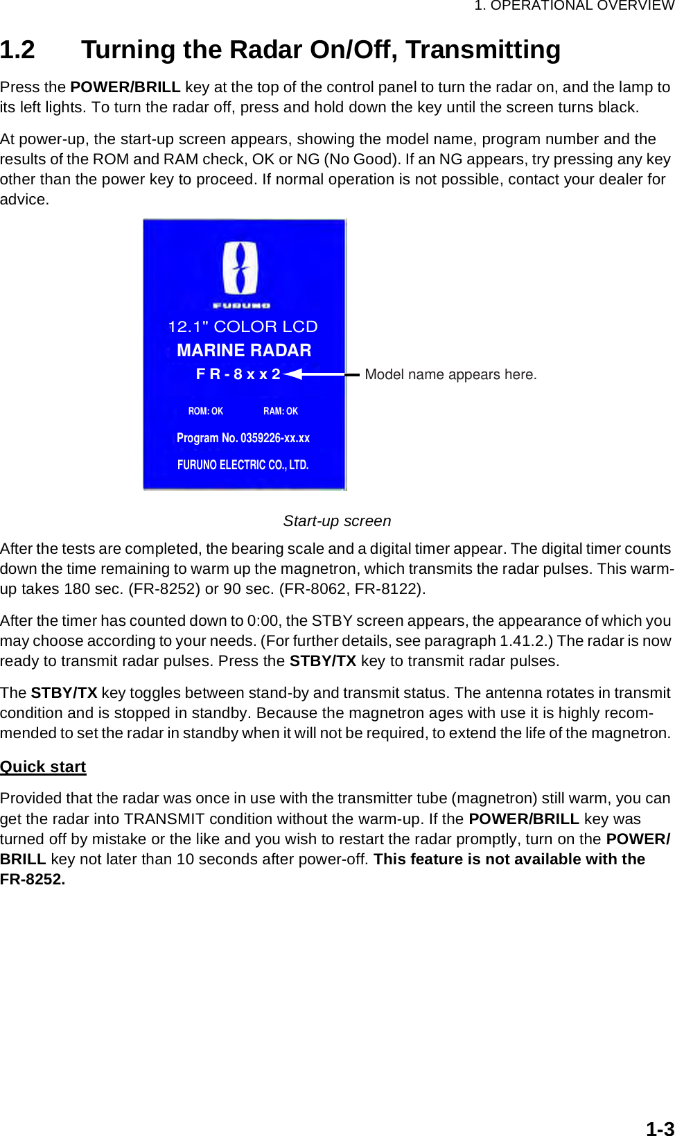
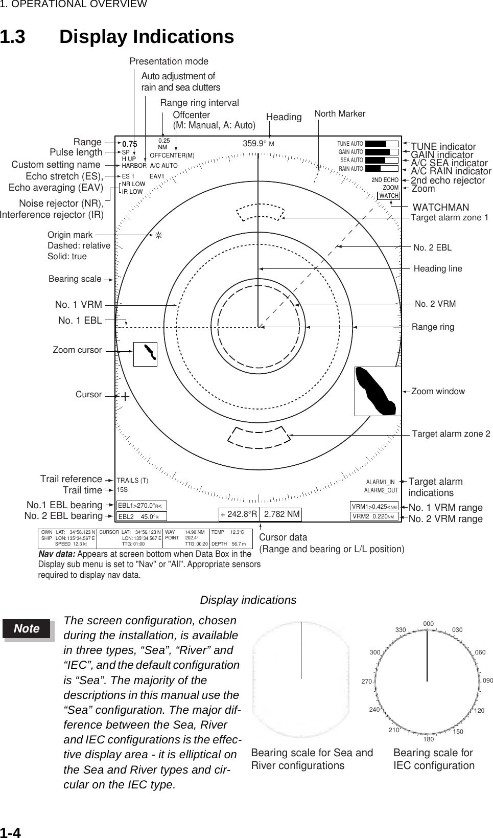
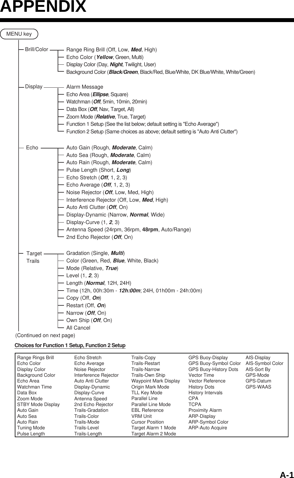
![1. OPERATIONAL OVERVIEW1-51.4 Adjusting Display Brilliance, Panel DimmerThe display brilliance and panel dimmer may be adjusted as follows:1. Press the POWER/BRILL key momentarily to show the Brill/Panel dialog box.Brill/Panel dialog box 2. Press the ENTER key to choose Brill or Panel, whichever you wish to adjust.3. Roll the trackball rightward or leftward to adjust. (For brilliance, you may also use the POWER/BRILL key.)4. Press the CANCEL/HL OFF key to close the window.1.5 Menu OverviewLess-often used functions are controlled through the menu, which consists of 15 menus and 5 sub menus. Below is the basic procedure for menu operation.1. Press the MENU key to display the menu.Menu2. Roll the trackball to choose a menu or sub menu. As you roll the trackball, the yellow (highlight) cursor in the Menu column indicates the menu currently selected and the menu items change according to the menu selected.W Min Max XBrill/PanelBrill (1 - 15) 15Panel (1 - 15) 15 [ENTER]: Select[CANCEL/HL OFF]: Close Brill/ColorEchoMarkTarget TrailsCustom 1 DisplayCustom 2Custom 3 GPS BuoyTargetARP*1AIS*2GPS*3 SystemTuningAuto Rain Pulse Length Auto Gain Auto Sea Echo StretchEcho Average:Long:Off:Off:Moderate:Moderate:ModerateDisplay-Dynamic Auto Anti ClutterDisplay-CurveNoise Rejector Interference Rejector 2nd Echo Rejector:Normal:2:Off:Off:Off:MedMenu EchoCursor*4Menu itemsand currentsettingsCurrently selected menuScroll bar(Indicates menus not currently shown in menu window.Black vertical line indicates location in menu.)[ENTER]: Enter [CANCEL/HL OFF]: Back[MENU]: Exit*1 Displayed if equipped with ARP Board.*2 Displayed if radar is interfaced with AIS transponder.*3 Dipslayed if radar is interfaced with GPS receiver.*4 Title bar is currently controllable column is blue; selected cursor is yellow. Title bar of inactive column is gray.MenuAntenna Speed :48rpmTitle bar*4Arrow meanssub menuspresent](https://usermanual.wiki/Furuno-USA/9ZWRTR086A.op-manual/User-Guide-1456648-Page-19.png)
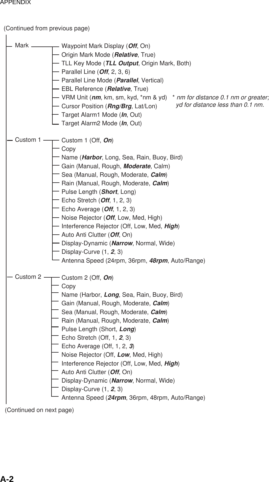
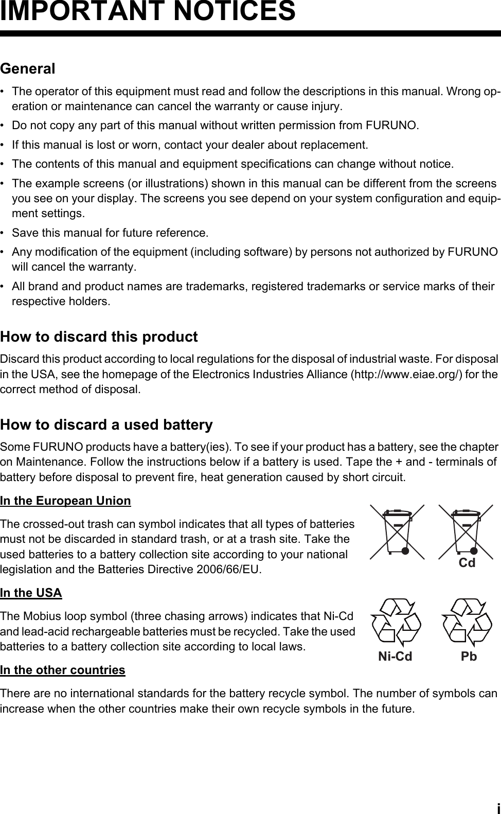
![1. OPERATIONAL OVERVIEW1-71.6 TuningThe radar receiver can be tuned automatically or manually, and the default tuning method is auto-matic. If you require manual tuning, do the following:1. Use the RANGE key to choose the 48-mile range.2. Press the MENU key to display the main menu.3. Use the trackball to choose Tuning and press the ENTER key.4. Use the trackball to choose Tuning Mode and press the ENTER key. Tuning options5. Choose Manual and press the ENTER key.6. Choose Manual Tuning and push the ENTER key. The window shown below appears.7. Roll the trackball upward or downward to adjust the tuning, watching the tuning bar at the top right corner. The best tuning point is where the tuning bar swings maximum. The vertical bar on the tuning bar shows tuning control position; not the tuning condition. Tuning indicator8. Push the ENTER key.9. Press the MENU key to close the menu.Brill/ColorEchoMarkTarget TrailsCustom 1 DisplayCustom 2Custom 3 GPS BuoyTargetARPAISGPS SystemTuning Tuning Mode Manual Tuning :Auto MenuTuning[ENTER]: Enter [CANCEL/HL OFF]: Back[MENU]: Exit:2048AutoManual2048(0-4095) Tuning method (Manual) Tuning barTUNE MANGAIN AUTOSEA AUTORAIN AUTO](https://usermanual.wiki/Furuno-USA/9ZWRTR086A.op-manual/User-Guide-1456648-Page-21.png)
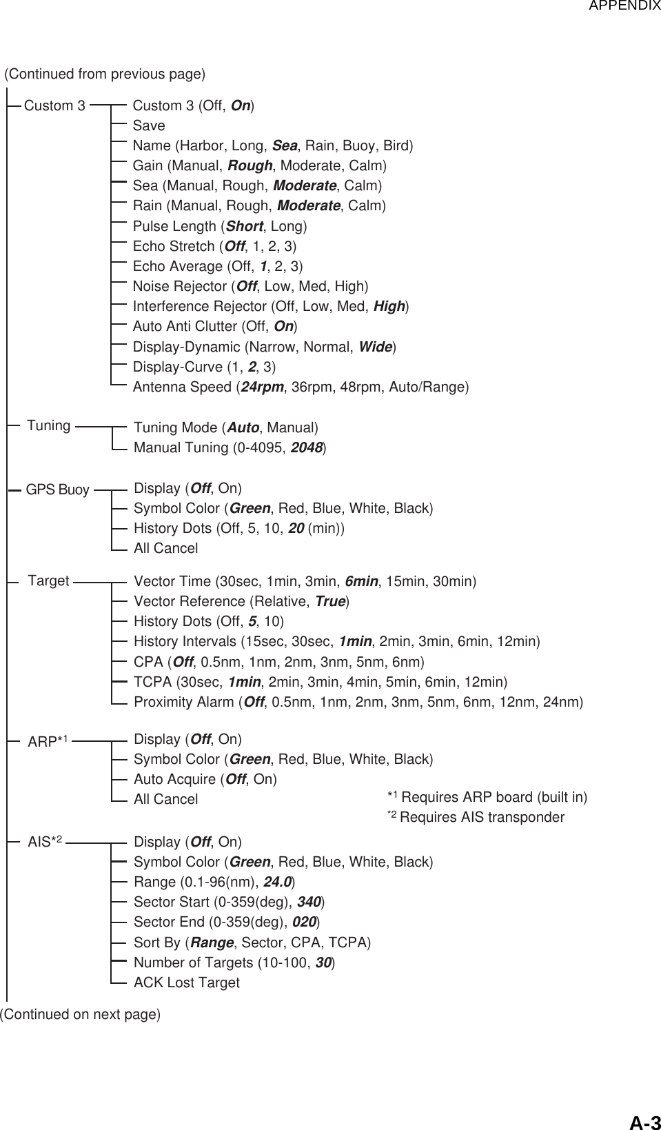
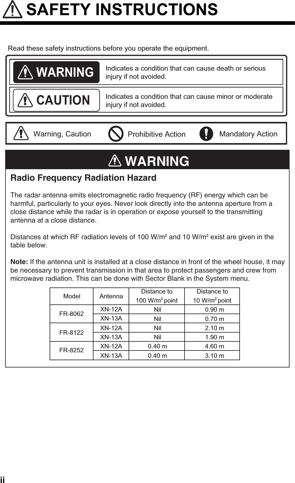
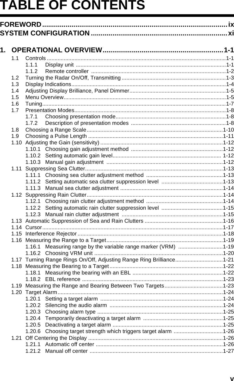
![1. OPERATIONAL OVERVIEW1-111.9 Choosing a Pulse LengthThe pulse length in use appears at the top left position on the screen. Appropriate pulse lengths are preset to individual range scales and custom setups. If you are not satisfied with the pulse length setting on the 1.5 nm or 3 nm range, you may change it as below. (Pulse length cannot be changed on any other ranges.) Use a longer pulse when your objective is long range detection, a shorter pulse when resolution is important.1. Press the MENU key to open the menu.2. Use the trackball to choose the Echo menu and press the ENTER key.3. Use the trackball to choose Pulse Length and press the ENTER key.4. Choose Short or Long as appropriate and press the ENTER key. 5. Press the MENU key to close the menu.Brill/ColorEchoMarkTarget TrailsCustom 1 DisplayCustom 2Custom 3 GPS BuoyTargetARPAISGPS SystemTuningAuto Rain Pulse Length Auto Gain Auto Sea Echo Stretch :Short:1:Off:Calm:Moderate:CalmNoise Rejector Echo AverageInterference Rejector DIsplay-DynamicDIsplay-CurveAntenna Speed2nd Echo Rejector:Normal:1:Off:Off:Off:OffMenu Echo[ENTER]: Enter [CANCEL/HL OFF]: Back[MENU]: ExitAuto Anti Clutter:48rpmShortLong](https://usermanual.wiki/Furuno-USA/9ZWRTR086A.op-manual/User-Guide-1456648-Page-25.png)
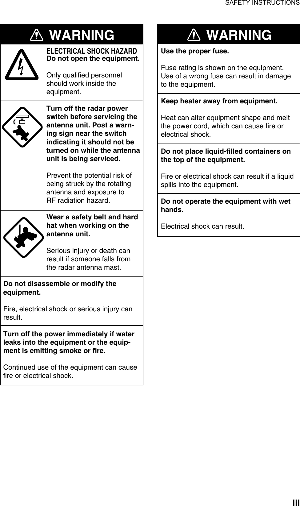
![1. OPERATIONAL OVERVIEW1-211.17 Turning Range Rings On/Off, Adjusting Range Ring Brilliance1. Press the MENU key to open the menu.2. Choose the Brill/Color menu and press the ENTER key.3. Choose Range Rings Brill and press the ENTER key.4. Choose appropriate brilliance and press the ENTER key. “Off” turns off the range rings.5. Press the MENU key to close the menu.Brill/ColorEchoMarkTarget TrailsCustom 1 DisplayCustom 2Custom 3 GPS BuoyTargetARPAISGPS SystemTuningDisplay Color Background Color Range Rings Brill Echo Color :Black/Green:Night:High MenuBrill/Color[ENTER]: Enter [CANCEL/HL OFF]: Back[MENU]: Exit:YellowOffLowMedHigh](https://usermanual.wiki/Furuno-USA/9ZWRTR086A.op-manual/User-Guide-1456648-Page-35.png)
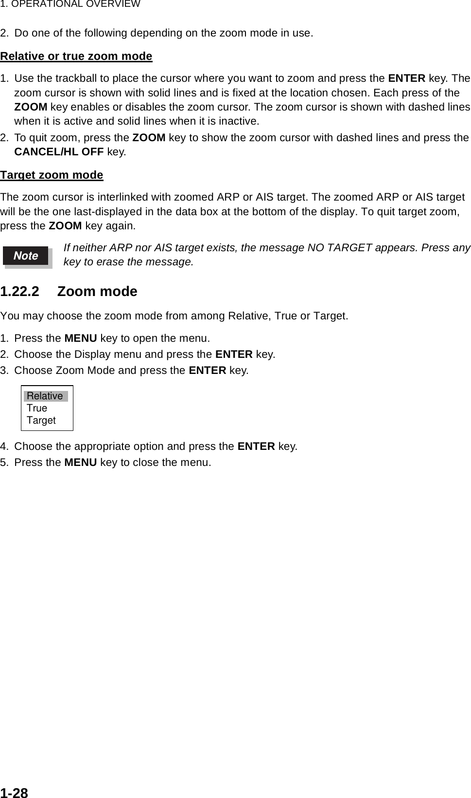
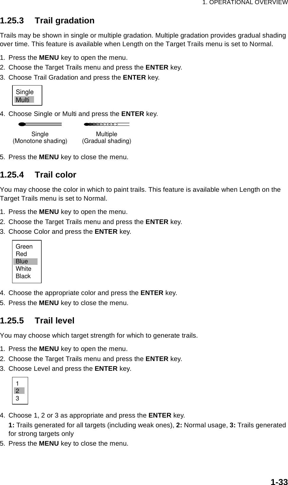
![1. OPERATIONAL OVERVIEW1-321.25.2 Trail modeYou may display echo trails in true or relative motion. Relative trails show relative movements between targets and own ship. True motion trails present true target movements in accordance with their over-the-ground speeds and course, and require a gyrocompass signal and own ship speed input.To choose trail mode, do the following:1. Press the MENU key to open the menu.2. Choose the Target Trails menu and press the ENTER key.3. Choose Mode and press the ENTER key.4. Choose the appropriate mode and press the ENTER key.5. Press the MENU key to close the menu.(a) True target trails (No smearing of stationary targets)(b) Relative target trails (Targets moving relative to own ship)Brill/ColorEchoMarkTarget TrailsCustom 1 DisplayCustom 2Custom 3 GPS BuoyTargetARPAISGPS SystemTuningMode Level Gradation Color LengthTime :2:24H:12h:00m:Relative:MultiOwn Ship NarrowAll CancelCopy Restart :Off:Off:Off:OffMenuTarget Trails[ENTER]: Enter [CANCEL/HL OFF]: Back[MENU]: Exit:GreenRelativeTrue](https://usermanual.wiki/Furuno-USA/9ZWRTR086A.op-manual/User-Guide-1456648-Page-46.png)
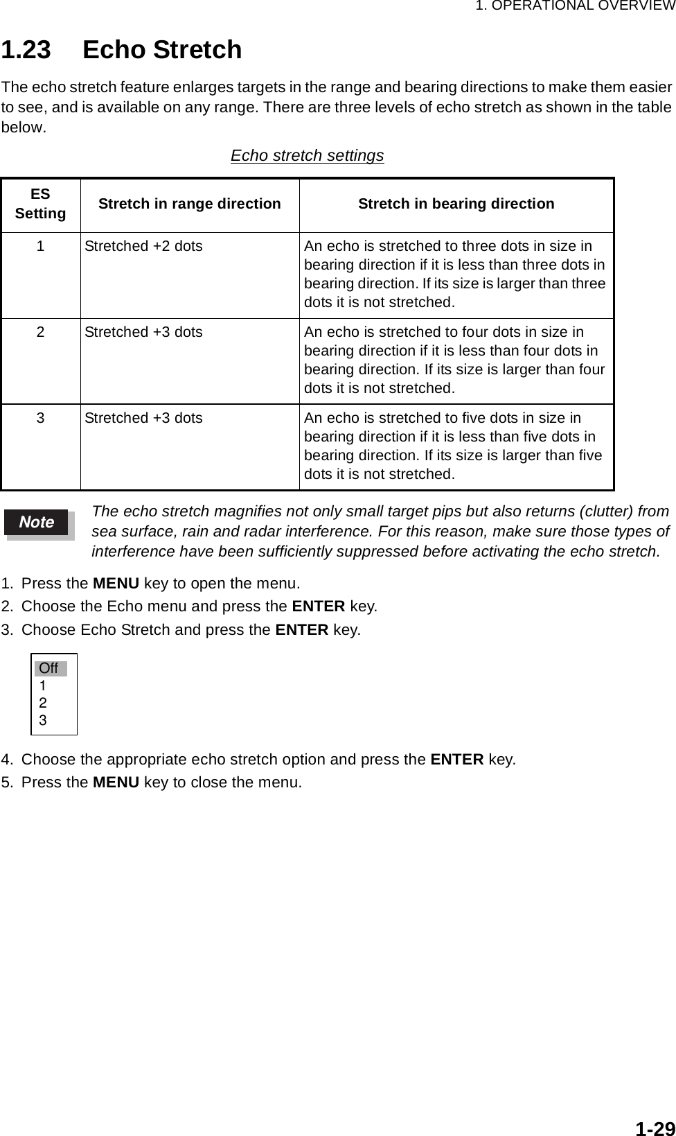
![1. OPERATIONAL OVERVIEW1-401.29.3 Setting custom setups1. Press the MENU key to show the menu.2. Choose Custom 1, Custom 2 or Custom 3 as appropriate and press the ENTER key.3. Choose Name and press the ENTER key to display the options shown right.4. Choose the name which best matches your desired objective and press the ENTER key.5. Set other menu items as appropriate.Note: For easy set up, you can copy the settings of the Echo menu (to Custom 1, Custom 2, Custom 3). Choose Copy and press the ENTER key. The message "Complete" appears upon completion of copying.6. Press the MENU key to close the menu.Sample custom setupsMenu item ApplicationName Harbor Long Sea Rain Buoy BirdGain Moderate Rough Calm Calm Moderate RoughSea Calm Calm Moderate Moderate Calm CalmRain Calm Calm Moderate Moderate Calm CalmPulse length Short Long Short Short Short LongEcho stretch Off 2 Off Off 1 2Echo average Off 3 1 1 or 2 1 or 2 3Noise rejector Off Low Off Off Off LowInt. rejector High High High Medium Medium MediumAuto anti-clutter Off Off On On Off OffDisplay-dynamic Narrow Narrow Wide Wide Normal NarrowDisplay-curve222222Antenna speed 48 rpm 24 rpm 24 rpm 24 rpm 24 rpm 24 rpmBrill/ColorEchoMarkTarget TrailsCustom 1 DisplayCustom 2Custom 3 GPS BuoyTargetARPAISGPS SystemTuningName Gain Custom 1 Copy SeaRain :Moderate:Calm:Calm:Harbor:OnNoise Rejector Echo AverageInterference RejectorPulse Length Echo Stretch DIsplay-Dynamic:Off:Off:Normal:Off:Short:1Menu Custom 1[ENTER]: Enter [CANCEL/HL OFF]: Back[MENU]: ExitAuto Anti Clutter :OffHarborLongSeaRainBuoyBird](https://usermanual.wiki/Furuno-USA/9ZWRTR086A.op-manual/User-Guide-1456648-Page-54.png)
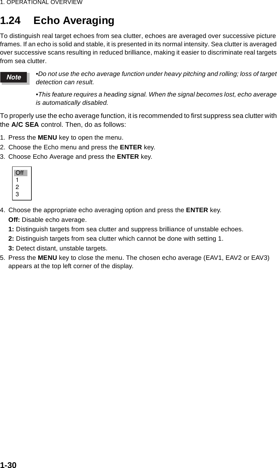
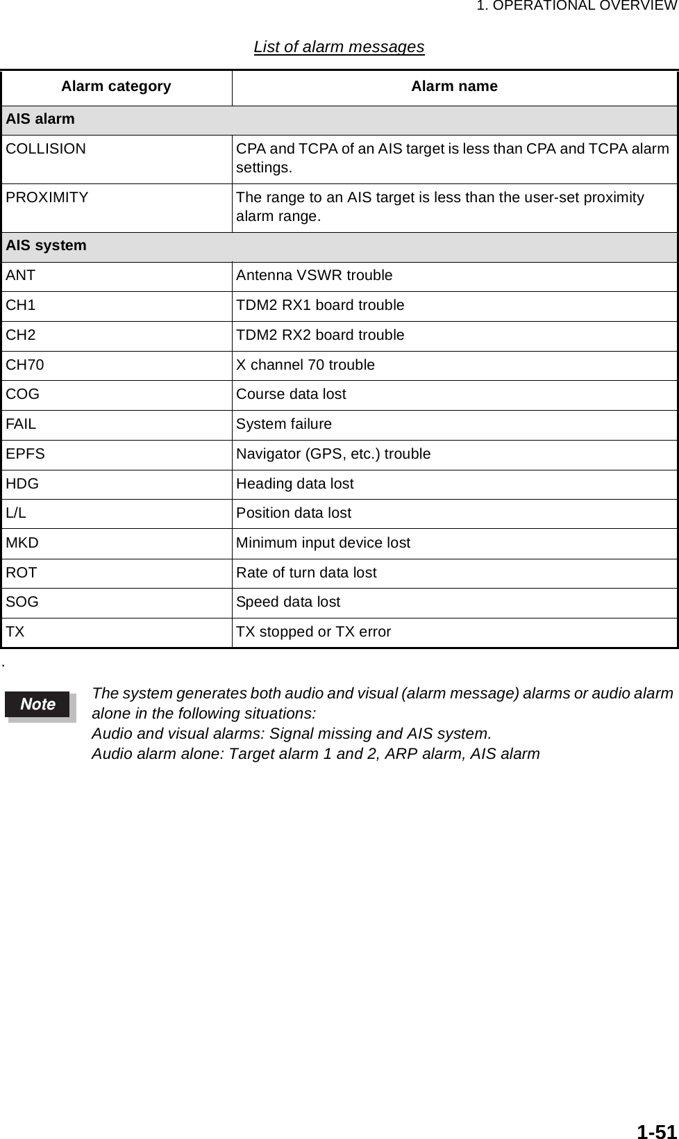
![1. OPERATIONAL OVERVIEW1-501.40 Alarm Message DisplayWhen trouble occurs the radar generates audio and/or visual alarms (See Note on next page) to alert you. The alarm message display shows all alarms currently violated. You may show this dis-play as follows:1. Press the MENU key to open the menu.2. Choose the Display menu and press the ENTER key.3. Choose Alarm Message and press the ENTER key.Alarm message displayTo close the alarm message display, press any key.List of alarm messagesList of alarm messagesAlarm category Alarm nameSignal missingBEARING Bearing signal lostGYRO AD-10 format gyro signal lostHEADING Heading signal lostNMEA-HEAD NMEA format heading signal lostPOSITION NMEA format position data lostTRIGGER Trigger signal lostVIDEO Video signal lostTarget alarmIN An echo has entered a target alarm zone.OUT An echo has exited a target alarm zone.ARP alarmCOLLISION CPA and TCPA of an ARP target is less than CPA and TCPA alarm settings.LOST Acquired ARP target becomes lost.PROXIMITY The range to an ARP target is less than the user-set proximity alarm range.Alarm Message[SIGNAL MISSING] TRIGGER HEADING BEARING GYRO VIDEO POSITION NMEA-HEAD[TARGET ALARM1] IN OUT [TARGET ALARM2] IN OUT[ARP ALARM] COLLISION LOST TARGET-FULL PROXIMITY[AIS ALARM] COLLISION PROXIMITY[AIS SYSTEM] TX ANT CH1 CH2 CH70 FAIL MKD EPFS L/L SOG COG HDG ROT <PLEASE PUSH ANY KEY - - TO STOP ALARM AND CLOSE THIS WINDOW>](https://usermanual.wiki/Furuno-USA/9ZWRTR086A.op-manual/User-Guide-1456648-Page-64.png)
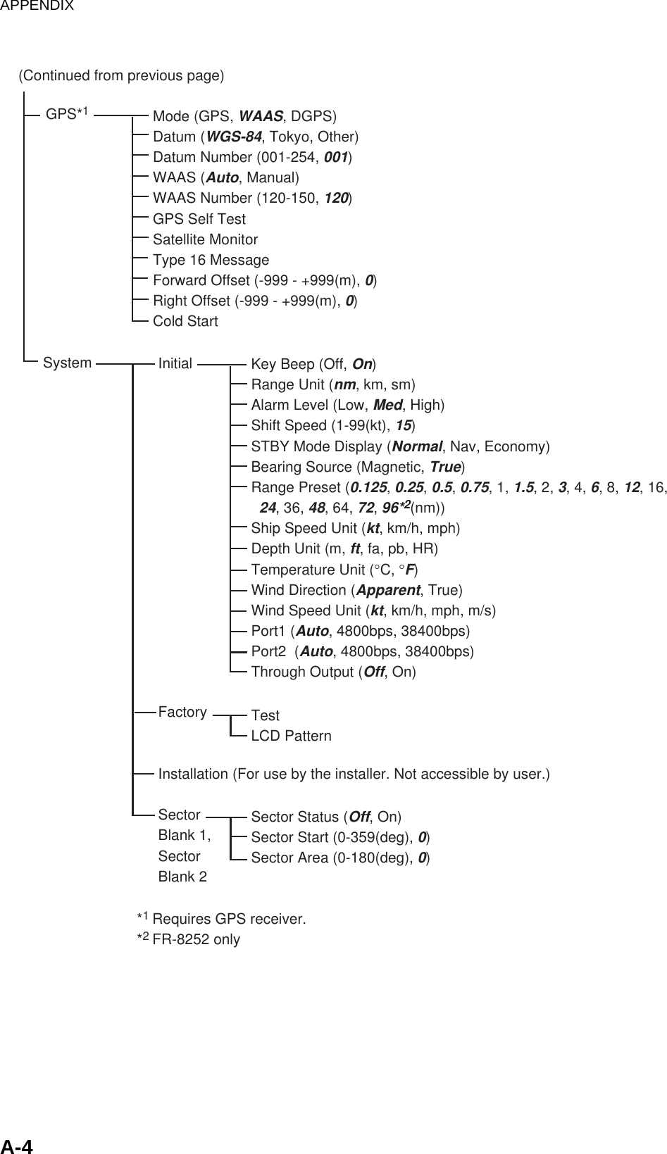
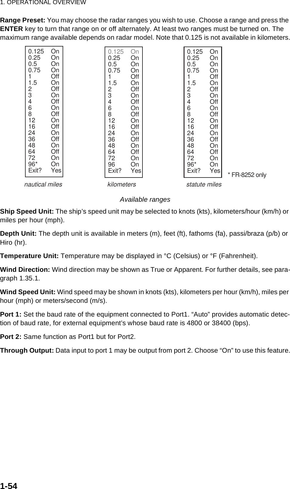
![1. OPERATIONAL OVERVIEW1-531.42 Customizing (Initial Menu)The Initial sub menu in the System menu contains items which allow you to customize your radar to meet your operational needs.1.42.1 Opening the Initial menu1. Press the MENU key to open the menu.2. Roll the trackball to choose System followed by Initial and press the ENTER key.Initial menu1.42.2 Description of Initial sub menuKey Beep: A beep sounds when a key are pressed. You may turn this beep on or off.Range Unit: Range may be shown in nm, km or sm.Alarm Level: The target alarm may be set to sound against weak, medium or strong echoes.Shift Speed: Set the ship’s speed to use calculate amount of display shift. The setting range is 1-99 (kts).STBY Mode Display: Set the function of the radar in standby. Normal: Display “STBY” at the screen center.Nav: Display navigation data.Economy: Extinguish the backlight of the LCD. The radar must be switched from TX to ST-BY to activate this mode.Bearing Source: Choose the type of bearing sensor connected to the radar; True (gyrocompass, satellite compass) or Magnetic (magnetic compass).[ENTER]: Enter [CANCEL/HL OFF]: Back[MENU]: ExitGPSMarkTarget TrailsCustom 1Custom 2Custom 3 TargetARPAISTuningMenuInitial System Initial Factory Key Beep : OnRange Unit : nm Alarm Level : MedShift Speed : 15 ktSTBY Mode Display : NormalBearing Source : TrueRange PresetShip Speed Unit : ktDepth Unit : ftTemperature Unit : °FWind Direction : ApparentWind Speed Unit : ktPort1 : AutoGPS Buoy Installation](https://usermanual.wiki/Furuno-USA/9ZWRTR086A.op-manual/User-Guide-1456648-Page-67.png)
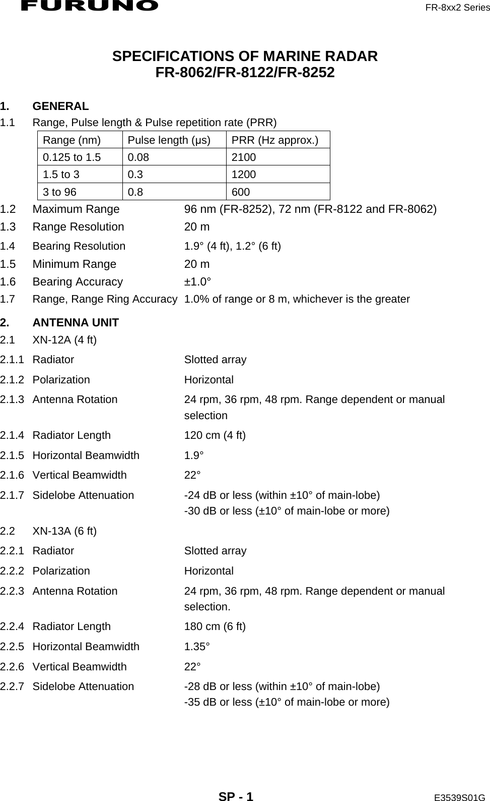
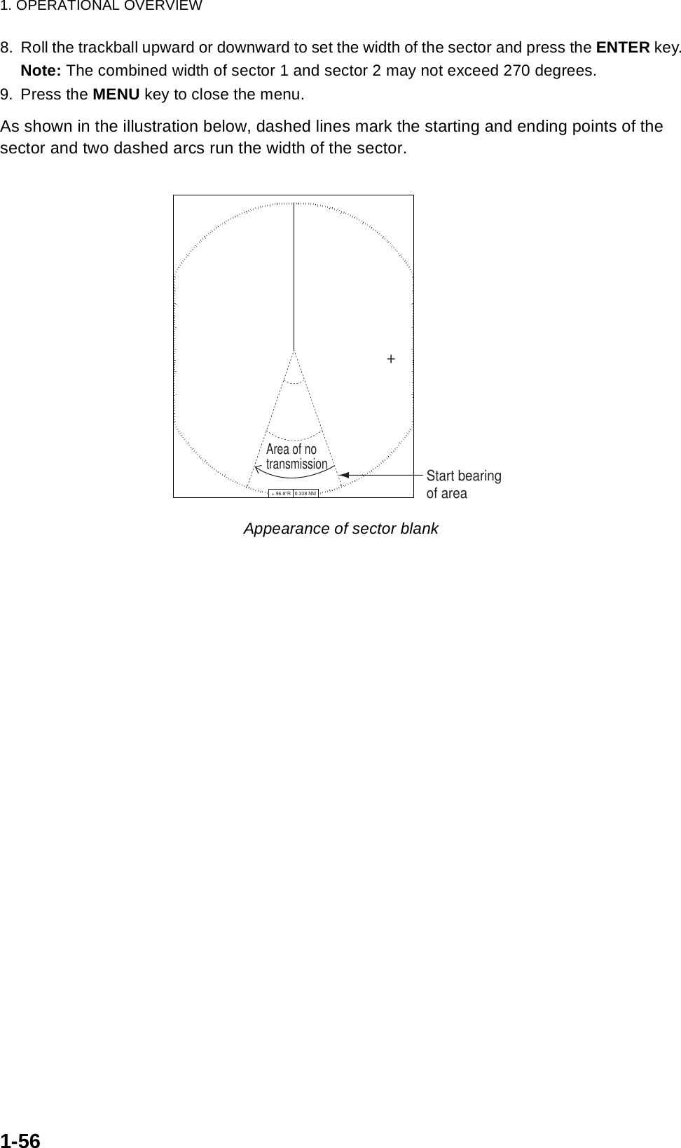
![1. OPERATIONAL OVERVIEW1-551.43 Sector BlankIt may be necessary to prevent transmission in a certain area to protect passengers and crew from microwave radiation. For example, if the antenna unit is installed at a close distance in front of the wheel house you would want to prevent transmission in that area. Two sectors can be set.1. Press the MENU key to open the menu.2. Choose Sector Blank 1 or Sector Blank 2 from the System menu and press the ENTER key.3. Choose Sector Status and press the ENTER key.4. Choose On and press the ENTER key.5. Choose Sector Start and press the ENTER key.6. Roll the trackball upward or downward to set the starting point of the sector and press the ENTER key.7. Choose Sector Area and press the ENTER key.Custom 1Custom 2Custom 3 Sector Status : OffSector Start : 0°Sector Area : 0°MenuSector Blank 1[ENTER]: Enter [CANCEL/HL OFF]: Back[MENU]: ExitTuningGPSTargetARPAIS SystemInitial FactoryInstallationSector Blank 1Sector Blank 2GPS BuoyOffOnS 0°T(0° - 359°)S 0°T(0° - 180°)](https://usermanual.wiki/Furuno-USA/9ZWRTR086A.op-manual/User-Guide-1456648-Page-69.png)
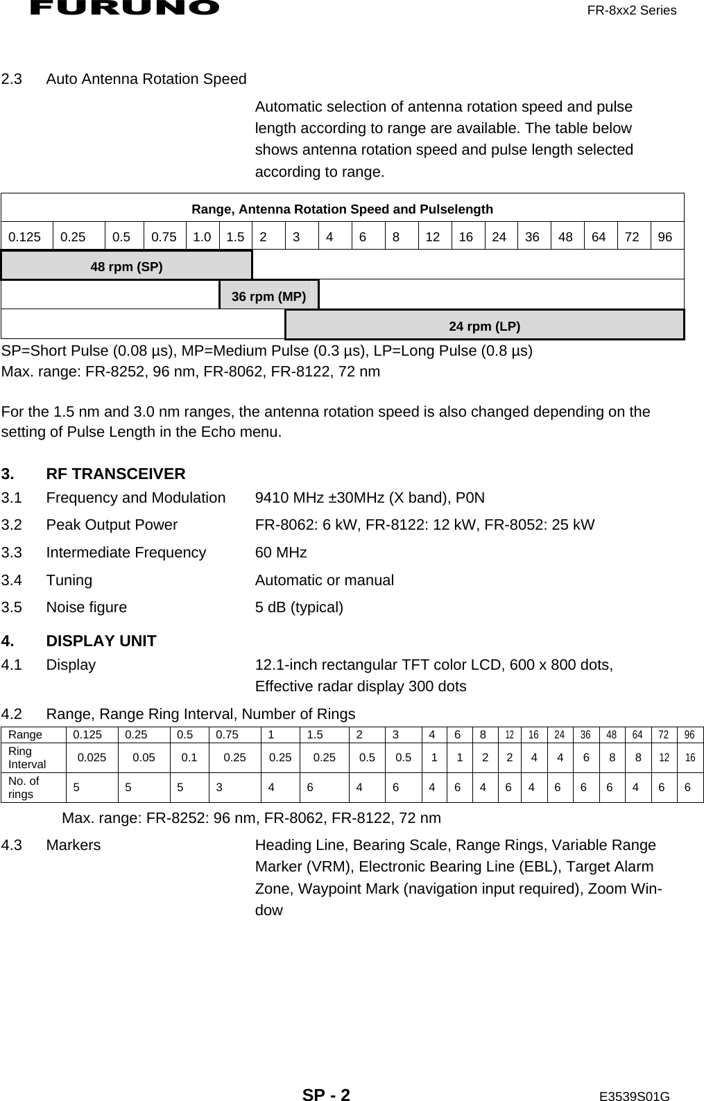
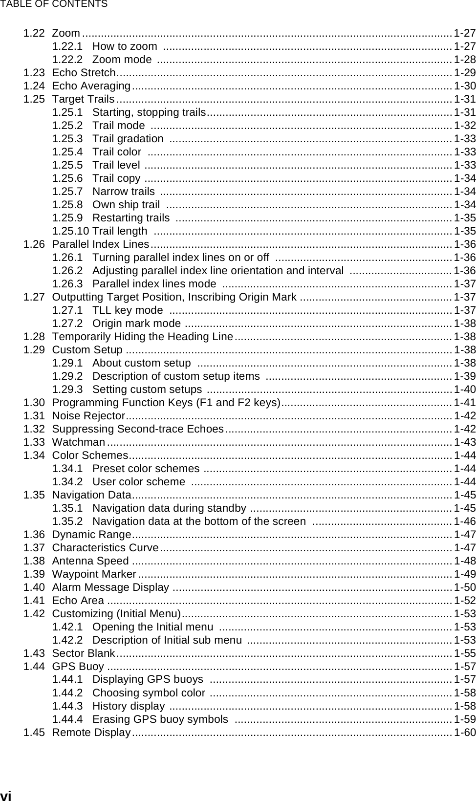
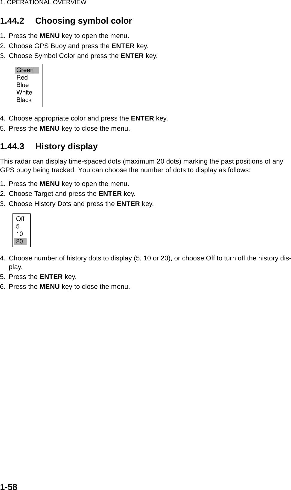
![1. OPERATIONAL OVERVIEW1-571.44 GPS BuoyWith connection of a GPS radio buoy locator, GPS buoy position can be monitored on the radar screen. One application of a GPS buoy is to tether it to a fishing net to monitor net position on the radar screen. Up to five buoys may be shown.GPS buoy symbols1.44.1 Displaying GPS buoys1. Press the MENU key to show the menu.2. Choose GPS Buoy and press the ENTER key.GPS buoy menu3. Choose Display and press the ENTER key.4. Choose Off or On as appropriate and press the ENTER key.5. Press the MENU key to close the menu.++ 96.8°R 0.338 NMGPS buoy0102GPS buoy no.GPS buoy'strackBrill/ColorEchoMarkTarget TrailsCustom 1 DisplayCustom 2Custom 3 GPS BuoyTargetARPAISGPS SystemTuningHistory Dots All Cancel Display Symbol Color :Off:Off MenuGPS Buoy[ENTER]: Enter [CANCEL/HL OFF]: Back[MENU]: Exit:Green](https://usermanual.wiki/Furuno-USA/9ZWRTR086A.op-manual/User-Guide-1456648-Page-71.png)

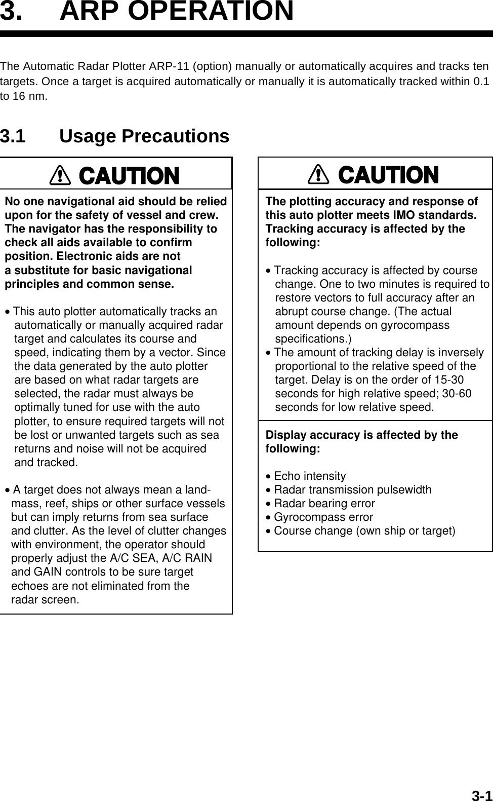
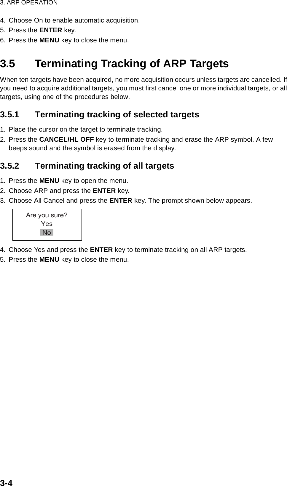
![3. ARP OPERATION3-23.2 Controls for Use with ARPENTER: Acquire cursor-selected target; displays data for tracked target (in the data box at the bottom of the screen).CANCEL/HL OFF: Remove data of cursor-selected tracked target from the data box; stops tracking cursor-selected target (when its data is not displayed in the data box).MENU: Access the Target and ARP menus for ARP operations.Trackball: Choose target to acquire, cancel tracking or show target data.3.3 ARP Display On/OffYou may turn off the ARP display as shown below.1. Press the MENU key to display the main menu.2. Use the trackball to choose ARP and press the ENTER key.ARP menu3. Use the trackball to choose Display and press the ENTER key. 4. Choose Off or On as appropriate and press the ENTER key.5. Press the MENU key to close the menu.Brill/ColorEchoMarkTarget TrailsCustom 1DisplayCustom 2Custom 3 TuningMenuARPSystemDisplay : OffSymbol Color : GreenAuto Acquire : OffAll Cancel[ENTER]: Enter [CANCEL/HL OFF]: Back[MENU]: ExitGPSTargetARPAISGPS BuoyOffOn](https://usermanual.wiki/Furuno-USA/9ZWRTR086A.op-manual/User-Guide-1456648-Page-84.png)
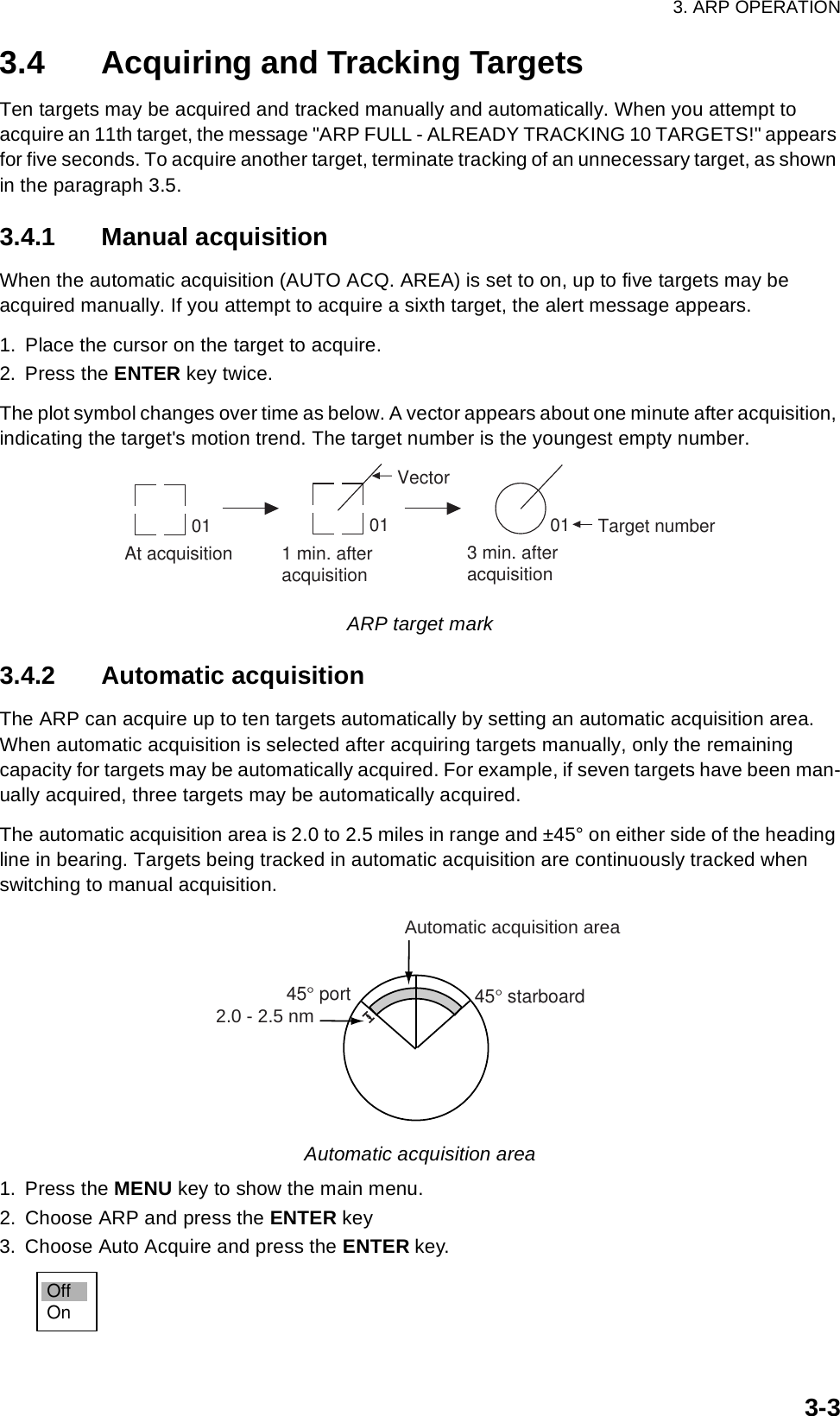
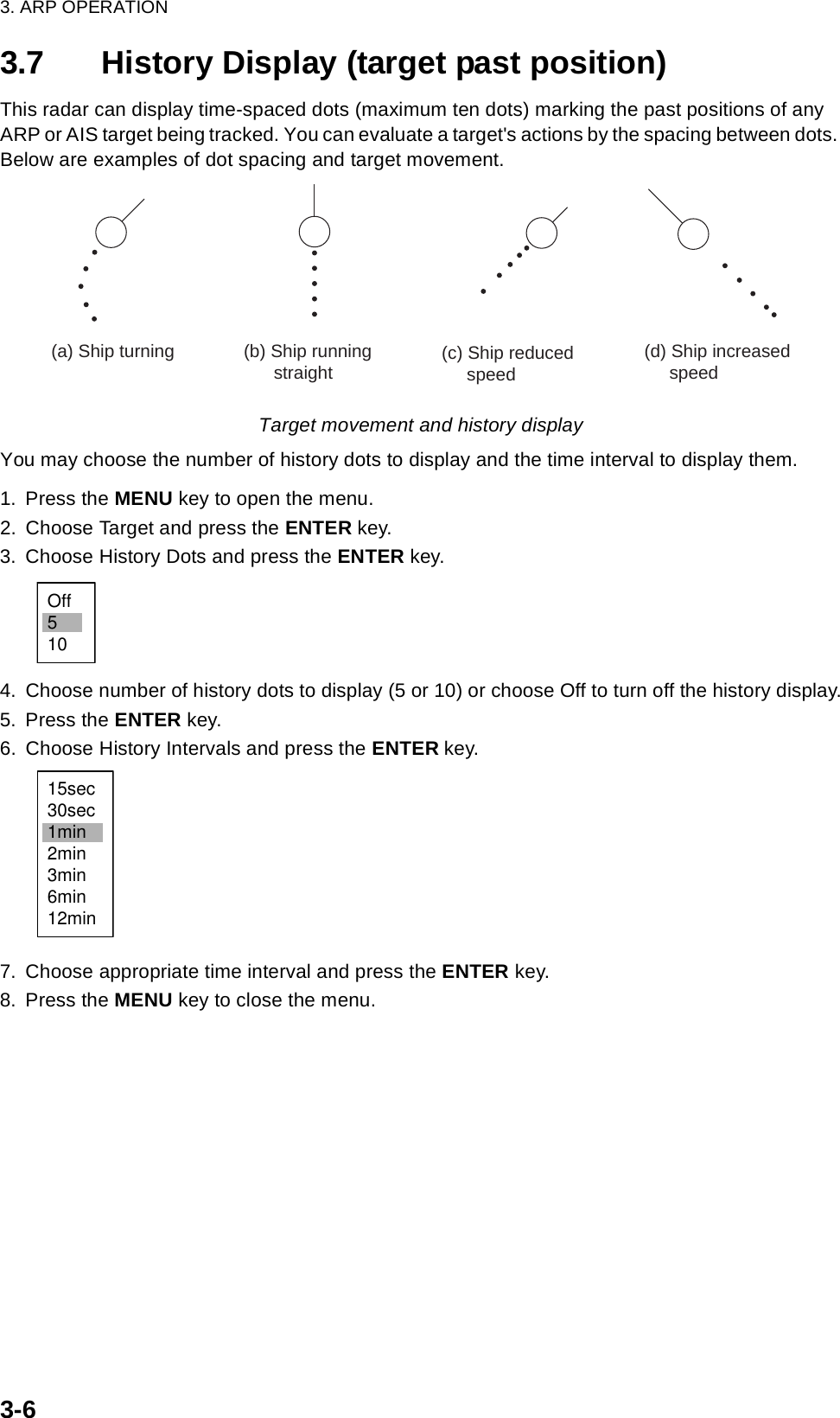
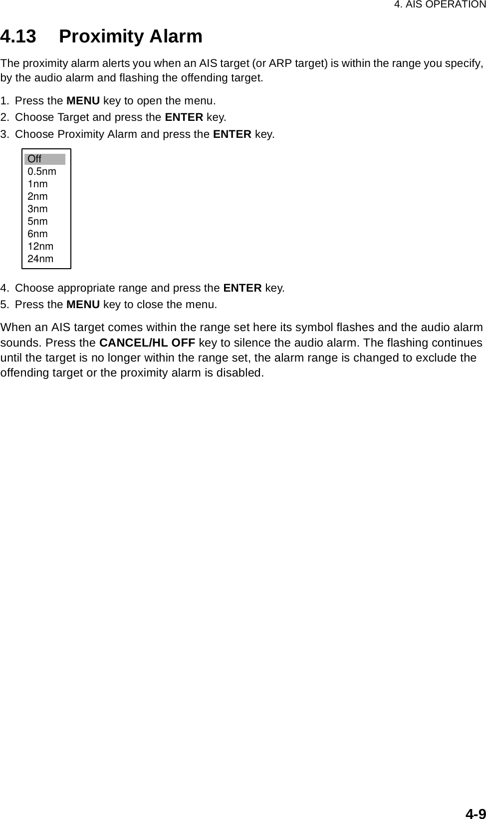
![3. ARP OPERATION3-53.6 Vector AttributesWhat is a vector?A vector is a line extending from a tracked target which shows speed and course of the target. The vector tip shows estimated position of the target after the selected vector time elapses. It can be useful to extend the vector length (time) in order to evaluate the risk of collision with any target.VectorVector time, vector referenceVector time can be set to 30 seconds, 1, 3, 6, 15 or 30 minutes. You may reference the vectors to North (True, requires heading and speed data) or ship's heading (relative) as desired. 1. Press the MENU key to open the menu.2. Choose Target and press the ENTER key.Target menu3. Choose Vector Time and press the ENTER key.4. Choose desired vector time and press the ENTER key.5. Choose Vector Reference and press the ENTER key.6. Choose Relative or True as appropriate and press the ENTER key. Relative: Other ships move relative to own ship. This mode is useful as an anti-collision aid. If a vessel is on a collision course with own ship its vector will be pointing toward own ship position. True: Own ship and other ships move at their true motions. This mode is useful for discriminating between moving and stationary targets. 7. Press the MENU key to close the menu.The functions of the Target menu are commonly shared by ARP and AIS.VectorBrill/ColorEchoMarkTarget TrailsCustom 1DisplayCustom 2Custom 3 TuningMenuTargetVector Time : 6minVector Reference : RelativeHistory Dots : 5History Intervals : 1minCPA : OffTCPA : 1minProximity Alarm : Off[ENTER]: Enter [CANCEL/HL OFF]: Back[MENU]: ExitGPSTargetARPAIS SystemGPS Buoy30sec1min3min6min15min30minRelativeTrueVector time choicesVector reference choicesNote](https://usermanual.wiki/Furuno-USA/9ZWRTR086A.op-manual/User-Guide-1456648-Page-87.png)
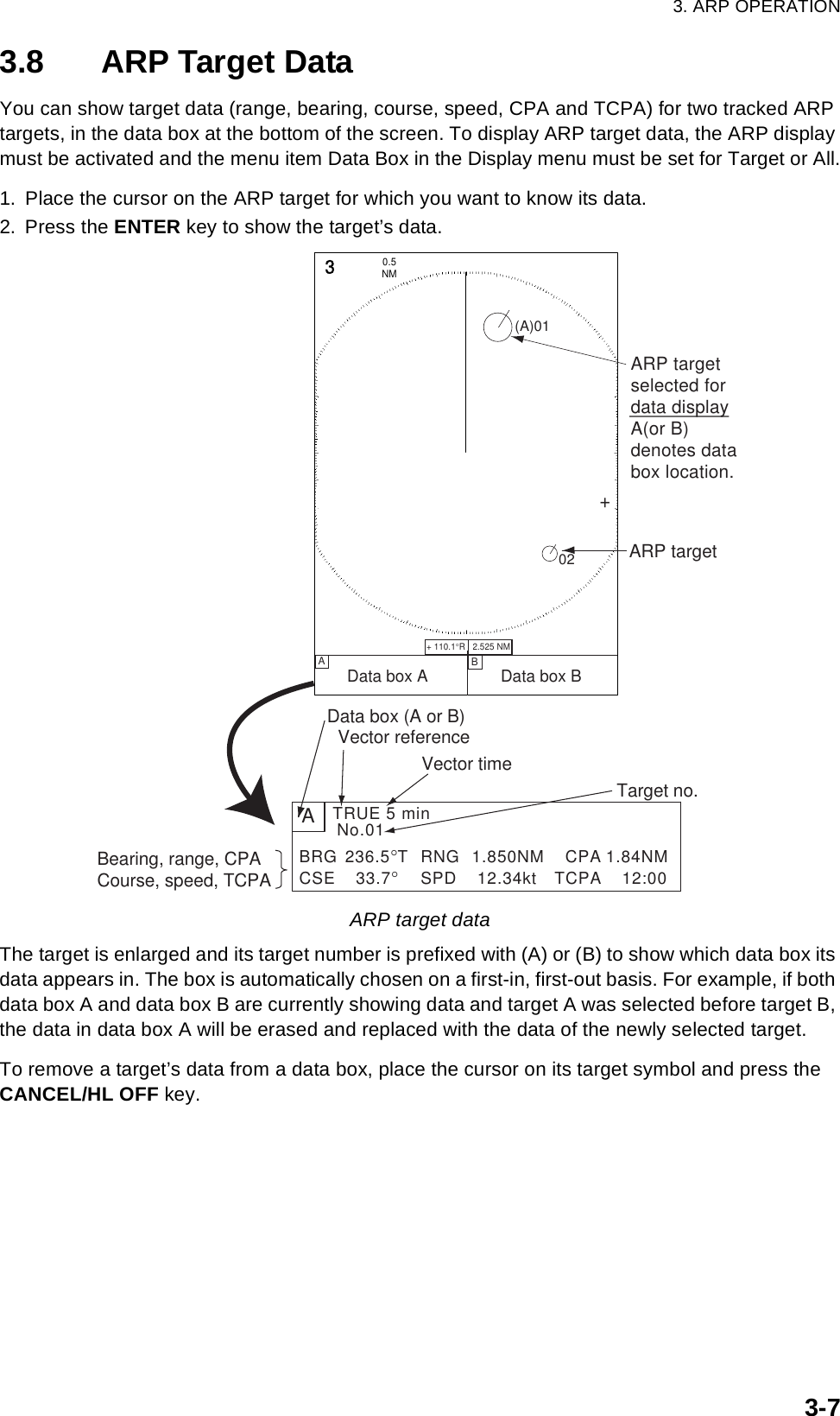
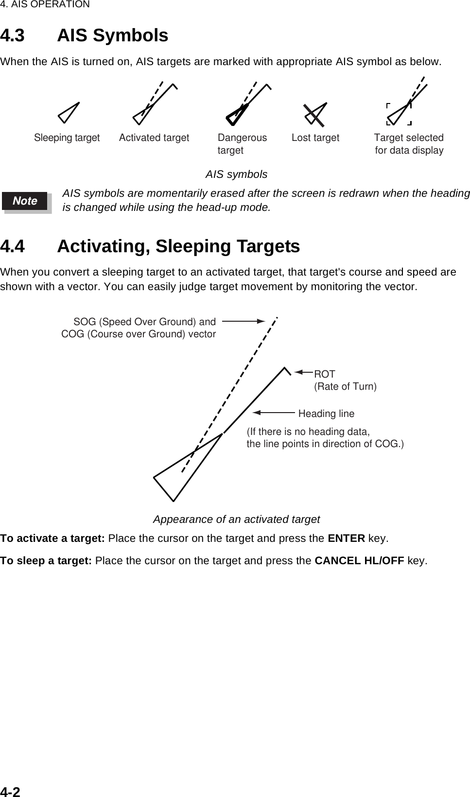
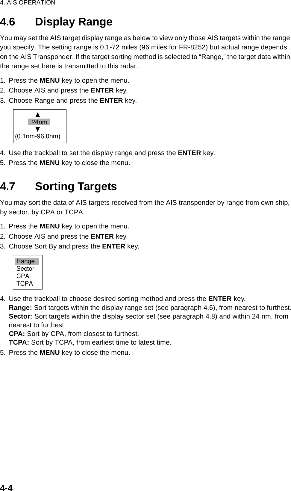
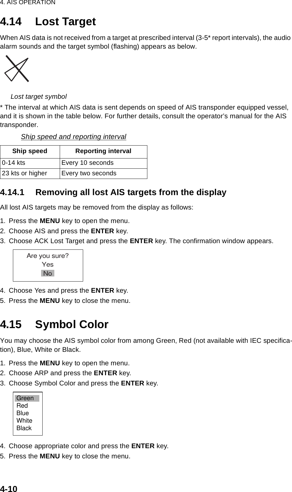
![4-14. AIS OPERATIONConnected to the FURUNO AIS Transponder FA-150, the FR-8xx2 series can show the name, position and other nav data of the nearest 100 AIS transponder-equipped ships. (For connection of other makes of AIS transponders, AIS Interface IF-1500AIS (option) is required.)This radar accepts position data fixed by WGS-84 geodetic datum. Set the datum to WGS-84 on the GPS navigator connected to this radar. If this radar is interfaced with the FURUNO GPS Nav-igator GP-320B, see paragraph 5.2 for the procedure. Additionally, confirm that Mode on the GPS menu is set to GPS or WAAS, referring to page 5-1. The AIS function is inoperative if the mode is DGPS.4.1 Controls for Use with AISENTER: Press, after choosing target with the trackball, to display data for selected active AIS target (in the data box at the bottom of the screen).CANCEL/HL OFF: Remove data of cursor-selected AIS target from the data box.MENU: Access the Target and AIS menus for AIS operations.Trackball: Choose active target to display its data.4.2 Turning the AIS Display On or OffYou may turn the AIS display on or off. The system continues processing AIS targets regardless of whether the AIS display is on or off, provided the AIS transponder is turned on.1. Press the MENU key to display the main menu.2. Choose AIS and press the ENTER key.AIS menu3. Choose DIsplay and press the ENTER key. 4. Choose Off (all AIS symbols are erased) or On (all AIS-received targets are displayed) as appropriate and press the ENTER key.5. Press the MENU key to close the menu.Brill/ColorEchoMarkTarget TrailsCustom 1DisplayCustom 2Custom 3 MenuAISDisplay : OffSymbol Color : GreenRange : 24.0nmSector Start : 340°Sector End : 20°Sort By : RangeNumber of Targets : 30ACK Lost Target[ENTER]: Enter [CANCEL/HL OFF]: Back[MENU]: Exit TuningGPSTargetARPAIS SystemGPS Buoy](https://usermanual.wiki/Furuno-USA/9ZWRTR086A.op-manual/User-Guide-1456648-Page-93.png)
![4. AIS OPERATION4-64.10 Vector AttributesWhat is a vector?A vector is a line extending from a tracked target which shows course of the AIS target. The vector tip shows estimated position of the target after the selected vector time elapses. It can be useful to extend the vector length (time) in order to evaluate the risk of collision with any target. (See the illustration on page 4-2 for the appearance of a vector.)Vector time, vector referenceVector time can be set to 30 seconds, 1, 3, 6, 15 or 30 minutes. Vectors may be displayed in True or Relative motion. 1. Press the MENU key to open the menu.2. Choose Target and press the ENTER key.Target menu3. Choose Vector Time and press the ENTER key.4. Choose desired vector time and press the ENTER key.5. Choose Vector Reference and press the ENTER key.6. Choose Relative or True as appropriate and press the ENTER key.Relative: Other ships move relative to own ship. This mode is useful as an anti-collision aid. If a vessel is on a collision course with own ship its vector will be pointing toward own ship position. True: Own ship and other ships move at their true motions. This mode is useful for discriminating between moving and stationary targets. 7. Press the MENU key to close the menu.8. Press the MENU key to close the menu.Brill/ColorEchoMarkTarget TrailsCustom 1DisplayCustom 2Custom 3 TuningMenuTargetVector Time : 6minVector Reference : RelativeHistory Dots : 5History Intervals : 1minCPA : OffTCPA : 1minProximity Alarm : Off[ENTER]: Enter [CANCEL/HL OFF]: Back[MENU]: ExitGPSTargetARPAIS SystemGPS Buoy30sec1min3min6min15min30minRelativeTrueVector time choicesVector reference choices](https://usermanual.wiki/Furuno-USA/9ZWRTR086A.op-manual/User-Guide-1456648-Page-98.png)
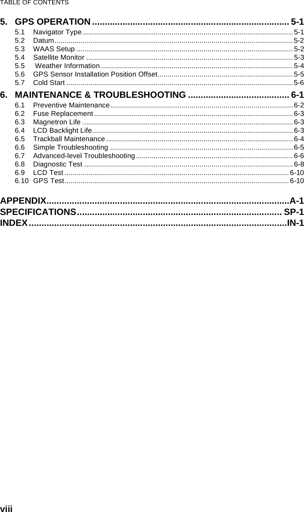
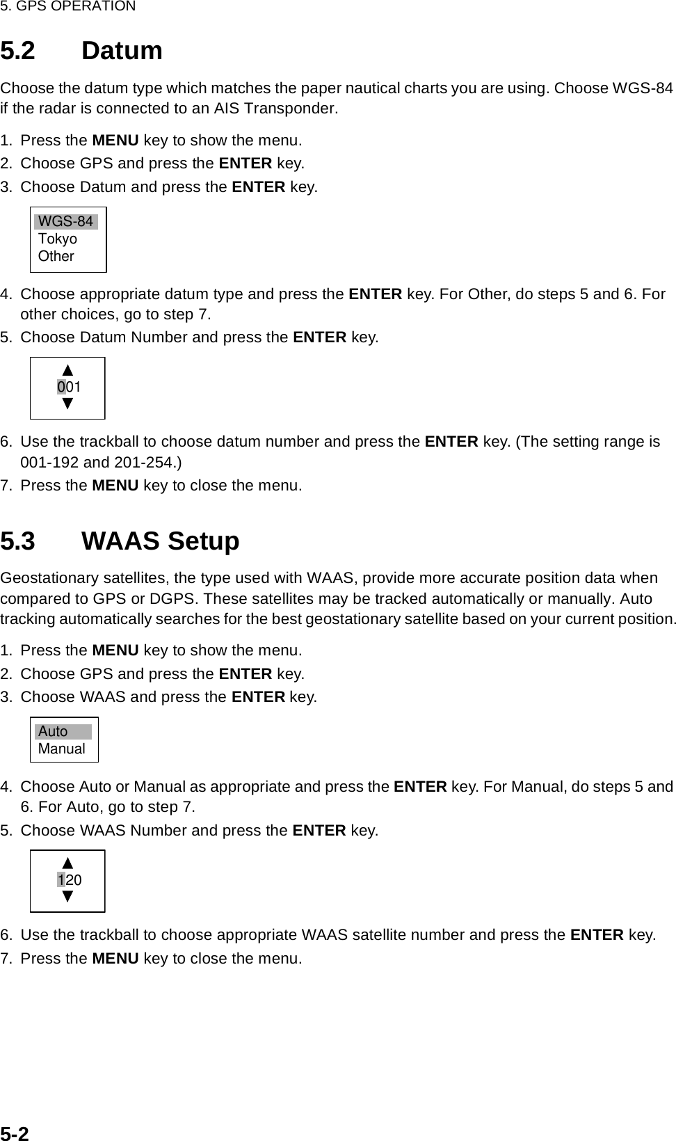
![5-15. GPS OPERATIONIf you are using the FURUNO GPS Navigator GP-320B, you may set it up from this radar.5.1 Navigator Type1. Press the MENU key to show the menu.2. Choose GPS and press the ENTER key.GPS menu3. Choose Type and press the ENTER key.4. Choose type of navigator connected to this radar and press the ENTER key. Note that GPS or WAAS should be selected if this radar is interfaced with an AIS Transponder. The AIS Tran-sponder will be inoperative if DPGS is selected.GPS: GPS Navigator GP-320B connectedWAAS: GPS Navigator GP-320B connectedDGPS: DPGS Beacon Receiver GR-80 connected.5. Press the MENU key to close the menu.Brill/ColorEchoMarkTarget TrailsCustom 1DisplayCustom 2Custom 3 MenuGPSType : WAASDatum : WGS-84Datum Number : 001WAAS : AutoWAAS Number : 120GPS Self TestSatellite MonitorType 16 MessageForward Offset : 0Right Offset : 0Cold Start[ENTER]: Enter [CANCEL/HL OFF]: Back[MENU]: ExitTuningGPSTargetARPAIS SystemGPS BuoyGPSWAASDGPS](https://usermanual.wiki/Furuno-USA/9ZWRTR086A.op-manual/User-Guide-1456648-Page-103.png)
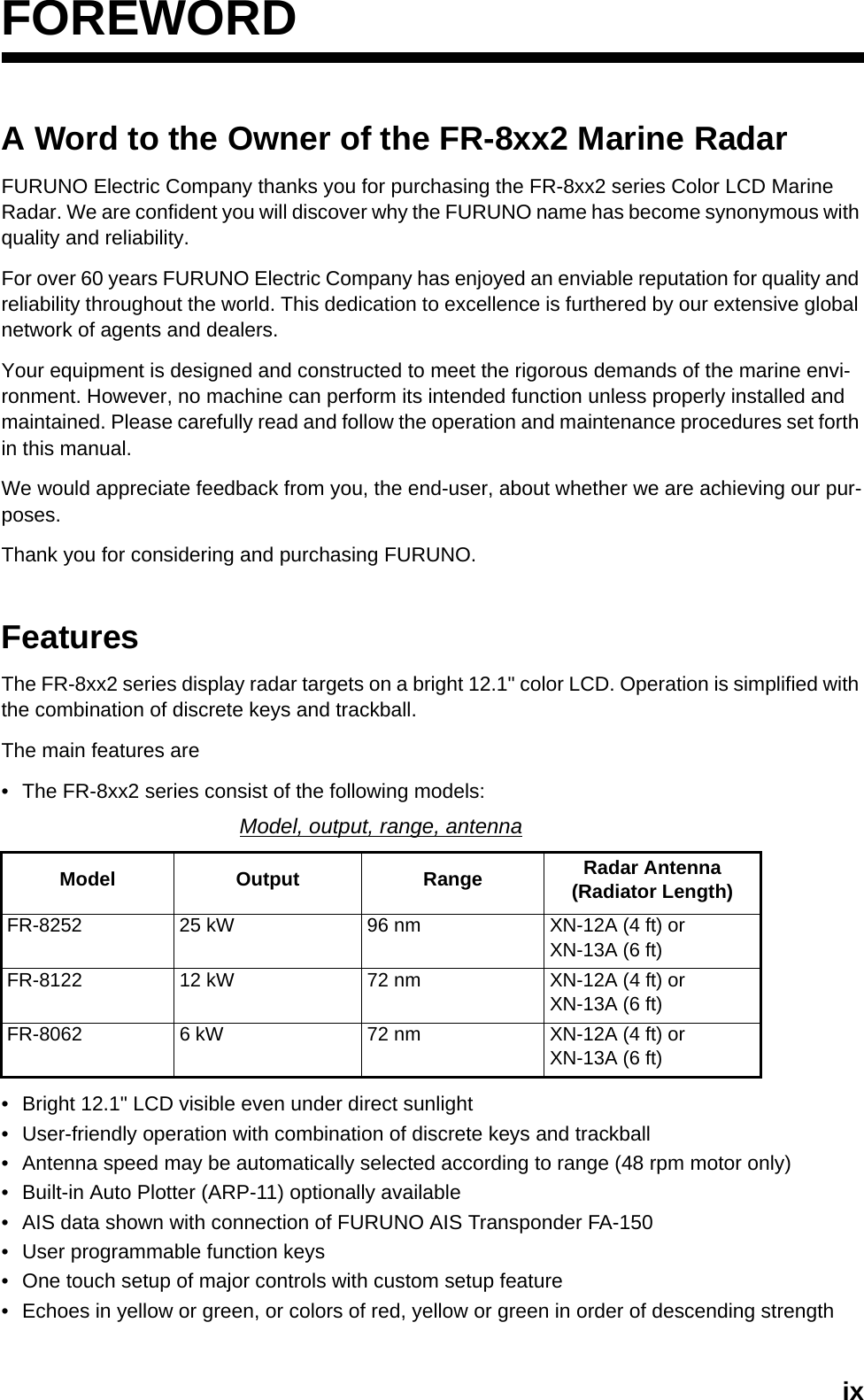
![5. GPS OPERATION5-35.4 Satellite MonitorThe Satellite Monitor provides comprehensive information about GPS and WAAS satellites. For more detailed information, see your GPS navigator’s owner’s manual.1. Press the MENU key to show the menu.2. Choose GPS and press the ENTER key.3. Choose Satellite Monitor and press the ENTER key.Satellite monitorTo close only the satellite monitor display, press the ENTER key.06D3D DOP1.5 85mDGPS StatusStation HealthDGPS DataSignal StrengthSignal SNROKOK10dB11dB13Altitude01GPSWAAS122416SNRSatellite No30 40 50122013118190607090813NorthmarkerDOP (Dilution of Precision, 0-99.0)SNR of tracked GPS satellitesSatellites whose SNR is above40 are used to fix position.GPS mode2D, 3D, D2DD3D, W2DW3D, DOPGPS satelliteno.WAASsatellite*Satellites in ring have elevationangle of 5°Satellites in ring have elevationangle of 45°OK or NG (No Good) displayedOK or NG (No Good) displayed 0-99 db, higher the better 0-99 db, higher the betterAltitude ofGPS antenafrom seasurfaceWAAS satelliteWN[MENU]: Close MENU [ENTER]: Close this window* Satellites used to fix position are shown in red.Satellite Monitor010924121918071316](https://usermanual.wiki/Furuno-USA/9ZWRTR086A.op-manual/User-Guide-1456648-Page-105.png)
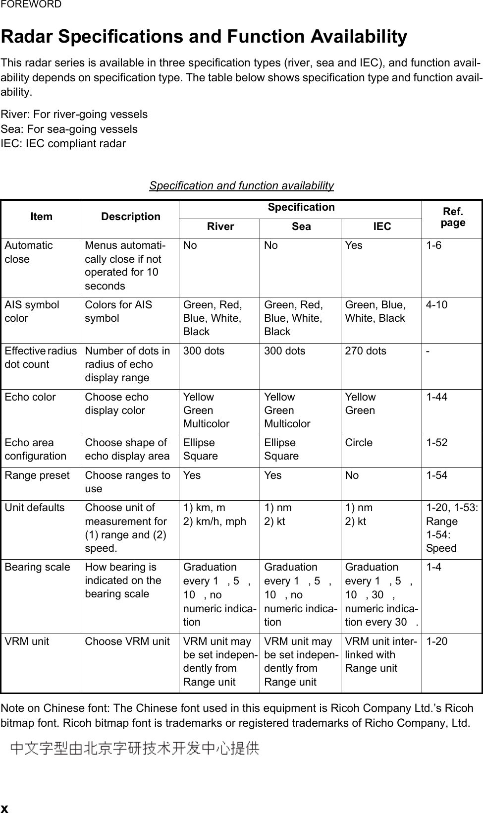
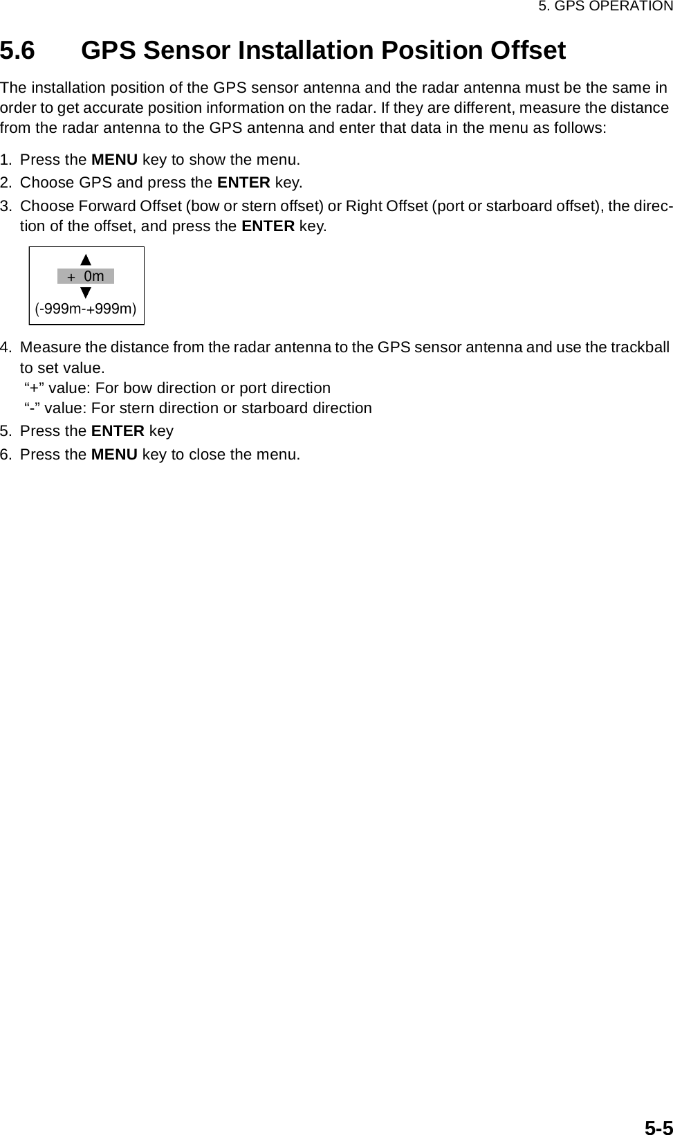
![5. GPS OPERATION5-45.5 Weather InformationThis radar can receive weather information from a japanese DPGS reference station if it is inter-faced with a DGPS beacon receiver (FURUNO GR-80, etc.) and your vessel is within the broad-casting range of a japanese DGPS reference station. The figure below shows an example of a weather information broadcast. This information is trans-mitted every five minutes, and two reports are provided for each observation point.This feature is valid only with japanese DGPS reference stations. No display or garbled characters appear if it is used elsewhere. 1. Press the MENU key to show the menu.2. Choose GPS and press the ENTER key.3. Choose Type 16 Message and press the ENTER key. (If no messages are present you cannot choose this menu item.) Type 16 messageWeather messages from as many as six DPGS reference stations are shown and the latest is at the top.The oldest message is erased when a new message arrives.4. To close only the message board, press the ENTER key.Type 16 MessagePoint Name Time Wind Pressure WaveDirection/SpeedMurotasakiKobeOsakakoOsekiTomgashimaShinomisaki13:2513:5513:4513:1513:5013:5513:3513:0513:3013:00ENENENWNNNWSSWSNWW5m10m5m10m5m10m5m10m5m10m1015hPa1016hPa1015hPa1017hPa1017hPa1017hPa1013hPa1015hPa1015hPa1016hPa10m13m11m10m9m10m8m9m5m10m13:3013:00 NWW5m10m 1015hPa1016hPa 5m10m[MENU]: Close MENU [ENTER]: Close this windowName of DGPSreference stationTimeWind directionand speed(16 compass pts.)Atmosphericpressure (0-9999 hPa)Wave height(0-99 m)Latest sixmessages](https://usermanual.wiki/Furuno-USA/9ZWRTR086A.op-manual/User-Guide-1456648-Page-106.png)
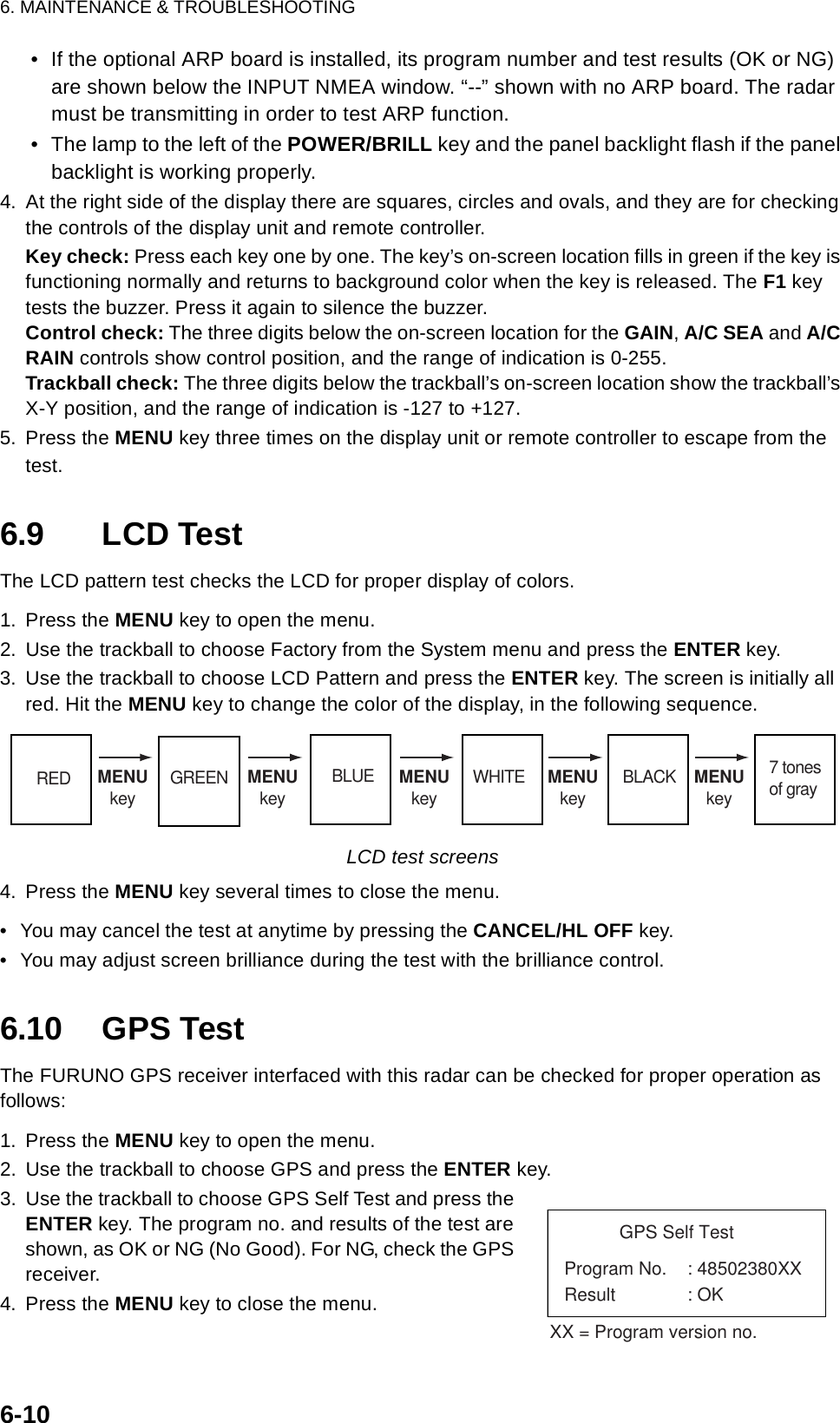
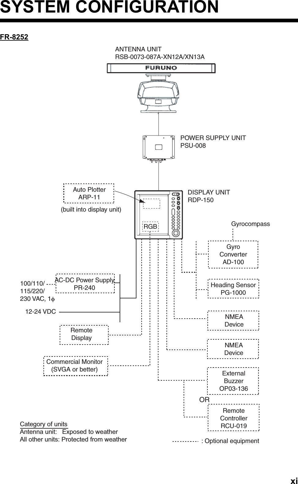
![6. MAINTENANCE & TROUBLESHOOTING6-86.8 Diagnostic TestThe diagnostic test checks the system for proper operation. It is primarily intended for use by ser-vice technicians, however the user may execute it to provide the service technician with informa-tion.1. Press the MENU key to open the menu.2. Use the trackball to choose Factory from the System menu and press the ENTER key.Factory menu3. Use the trackball to choose Test and press the ENTER key.MarkTarget TrailsCustom 1Custom 2Custom 3 TestLCD PatternMenuFactory[ENTER]: Enter [CANCEL/HL OFF]: Back[MENU]: ExitTuningGPSTargetARPAIS System Initial Factory InstallationGPS Buoy](https://usermanual.wiki/Furuno-USA/9ZWRTR086A.op-manual/User-Guide-1456648-Page-116.png)
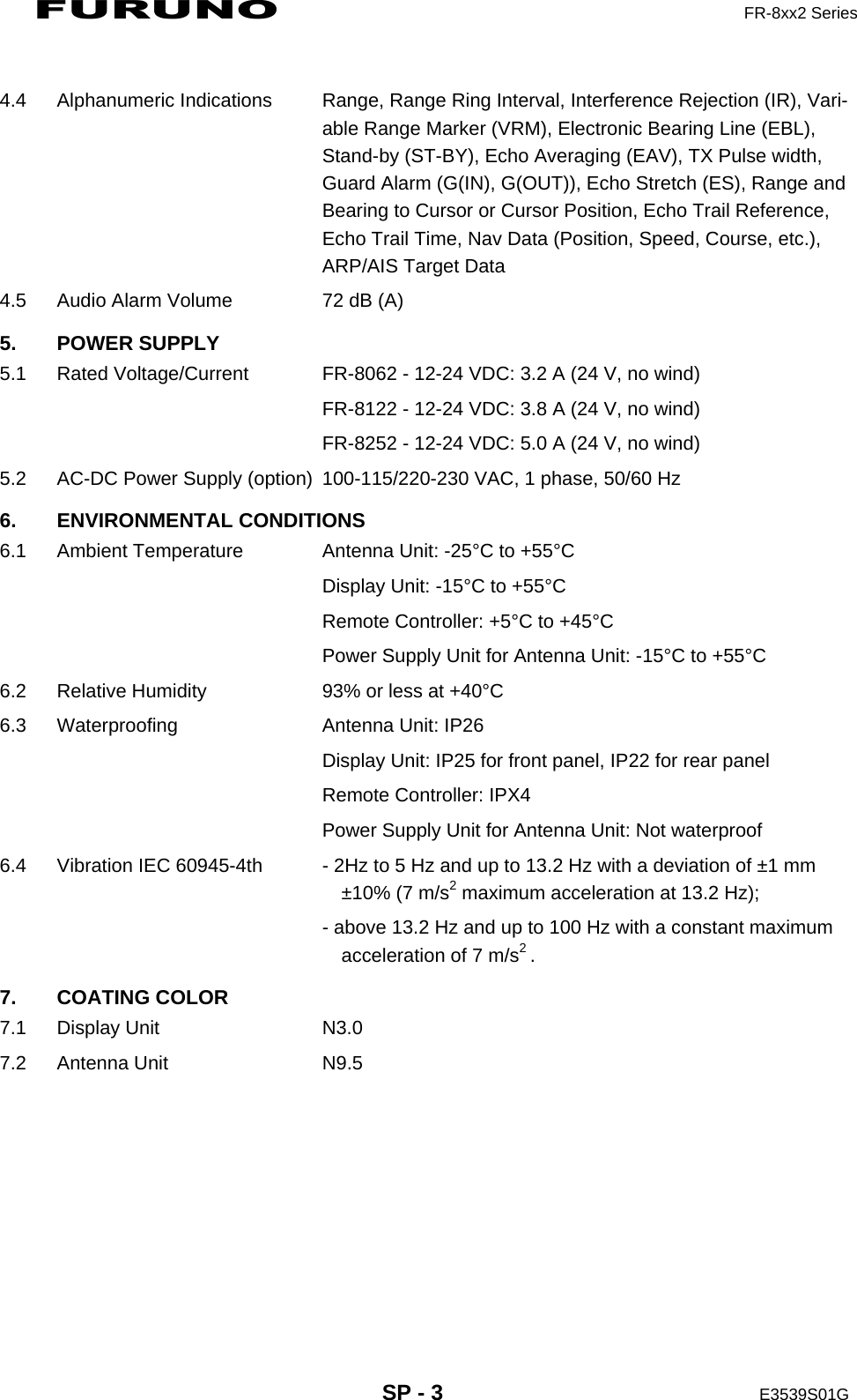
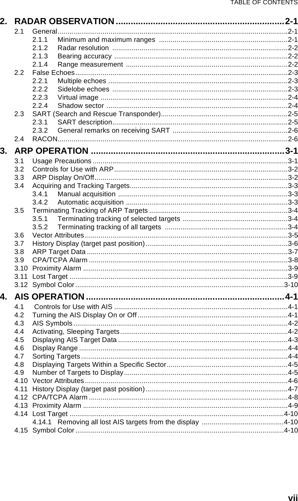
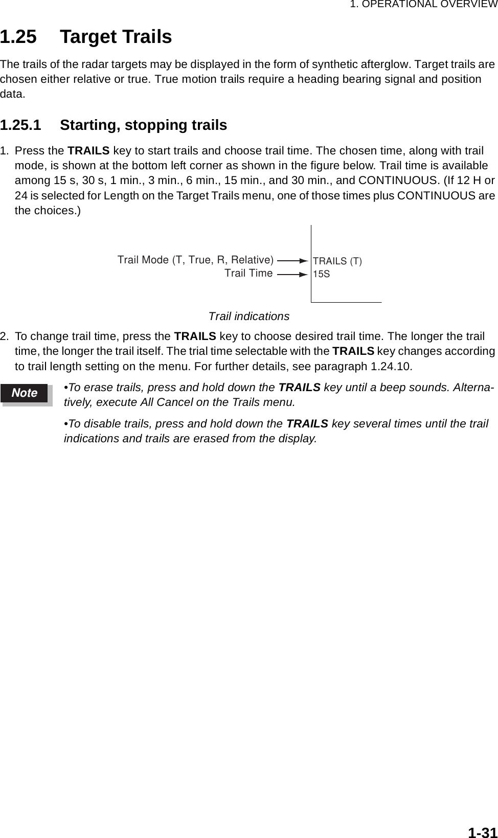
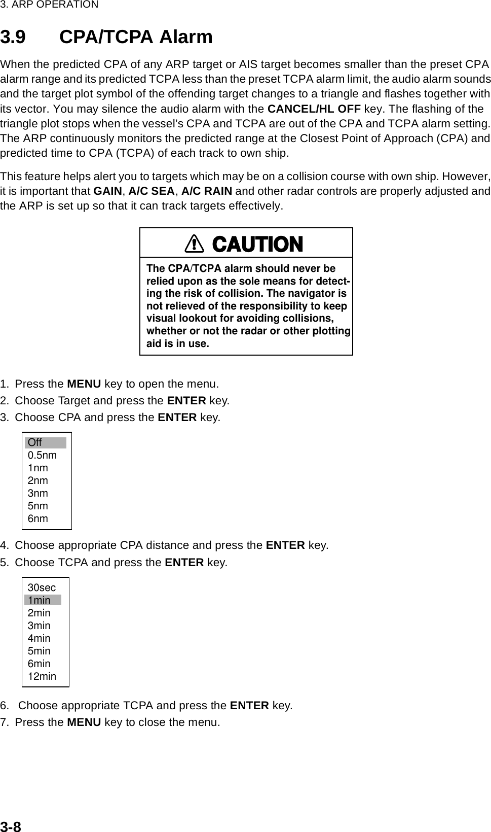
![6. MAINTENANCE & TROUBLESHOOTING6-9DIagnostics screen• At the top of the screen the results of the ROM, RAM and data ports NMEA1, NMEA2 and RS232C are displayed as OK or NG (No Good). For any NG contact your dealer for advice. (Ports NMEA1, NMEA2 and RS-232C require a special test connector in order to test them. “- -” is shown when no test connector is connected.) PROGRAM NUMBER and FPGA VERSION show respective program number and program version number (XXXX).• Heading and bearing signals are checked for proper input and the result displayed as OK or NG. Tune and indicator voltages, antenna rotation speed, antenna motor voltage, echo level and trigger frequency are measured and shown. TOTAL ON TIME and TOTAL TX TIME show the total number of hours the radar has been powered and trans-mitted, respectively.• The INPUT NMEA window shows all the NMEA sentences being input to this radar. Sen-tences are updated every second.INPUT NMEAROM : OKRAM : OKNMEA1 : - -NMEA2 : - -RS-232C : - -PROGRAM NUMBER : 0359226-XX.XXFPGA VERSION : 㪇㪊㪌㪐㪉㪉㪐㪄㪯㪯㪅㪯㪯HEADING : OK GYRO (AD-10) 245.2°BEARING : OKTUNE VOLTAGE : 10.1 VINDICATOR VOLTAGE : 4.2 VANTENNA ROTATION : 48.1 rpmMOTOR VOLTAGE : 23.4 VECHO LEVEL : -40 dBmTRIGGER FREQUENCY : 2100 HzTOTAL ON TIME : 123456.7 hTOTAL TX TIME : 987654.3 hARP-11 PROGRAM NUMBER: 1859127XXXARP-11 : OK[MENU] x 3: Exit [F1]: Alarm Test<REMOTE CONTROLLER>+000+000000000000BWC: GPBWC, 151130. 00, 3448. 50, N, 13510. 30, E, 40. 0, T, 47. 2, M, 3. 05, N, , A*7FBWR:DBT:DPT:GGA:GLL:GNS:HDG:HDM:HDT:MTW:MWV:RMB:RMC:VHW:VTG:VWT:VWR:XTE:ZDA:](https://usermanual.wiki/Furuno-USA/9ZWRTR086A.op-manual/User-Guide-1456648-Page-117.png)