Furuno USA 9ZWRTR087 Marine Radar User Manual
Furuno USA Inc Marine Radar
UserManual.wiki
>
Furuno USA
>
9ZWRTR087 User Manual
Users manual
Navigation menu
Upload a User Manual
Namespaces
Wiki Guide
HTML
PDF
Info
Views
User Manual
Discussion / Help
Navigation
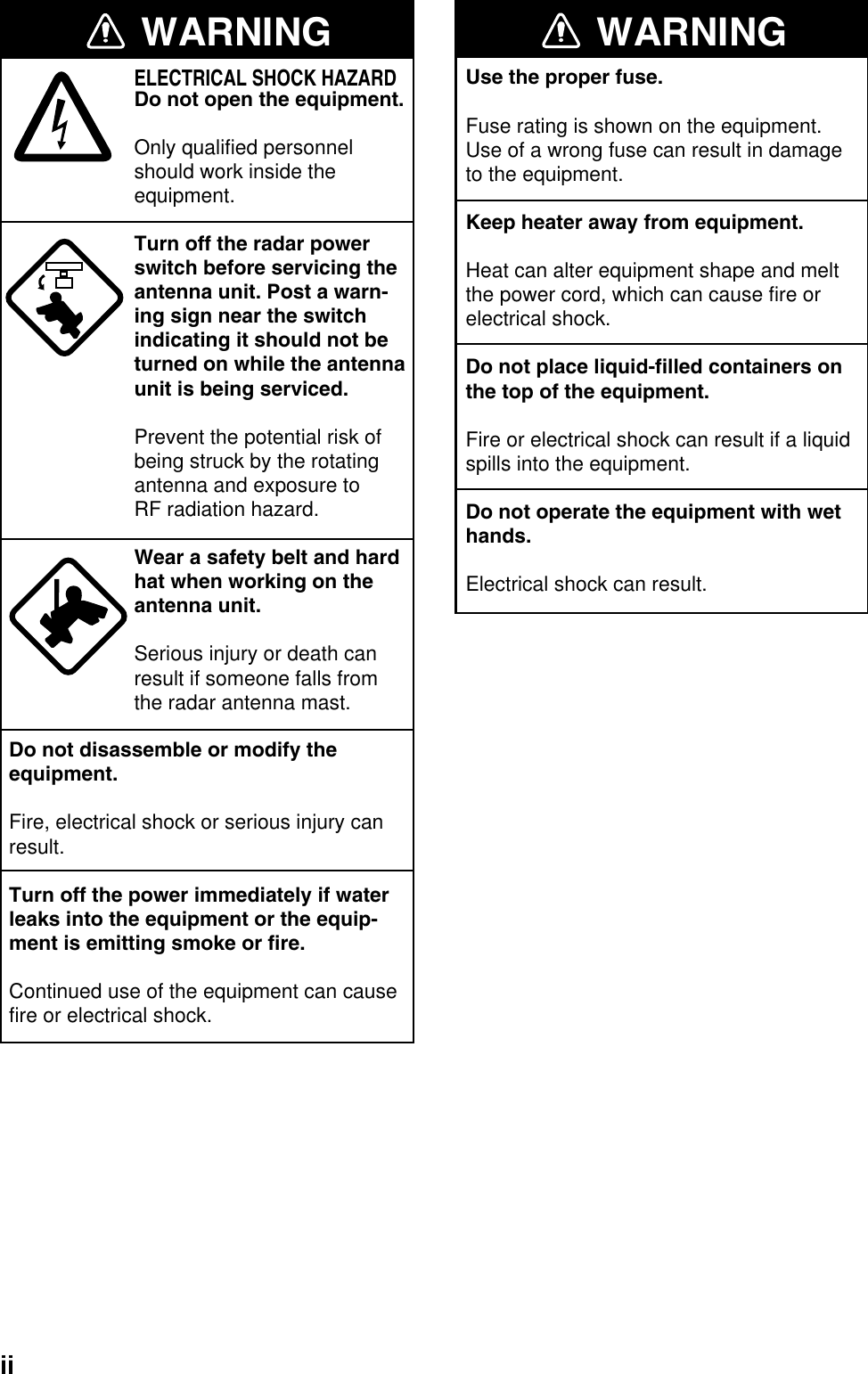

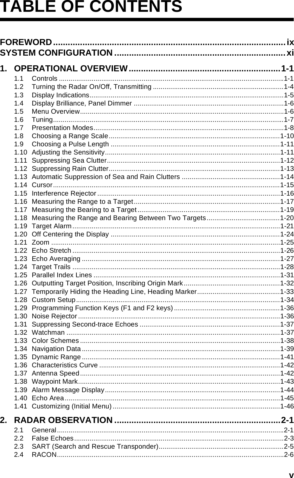
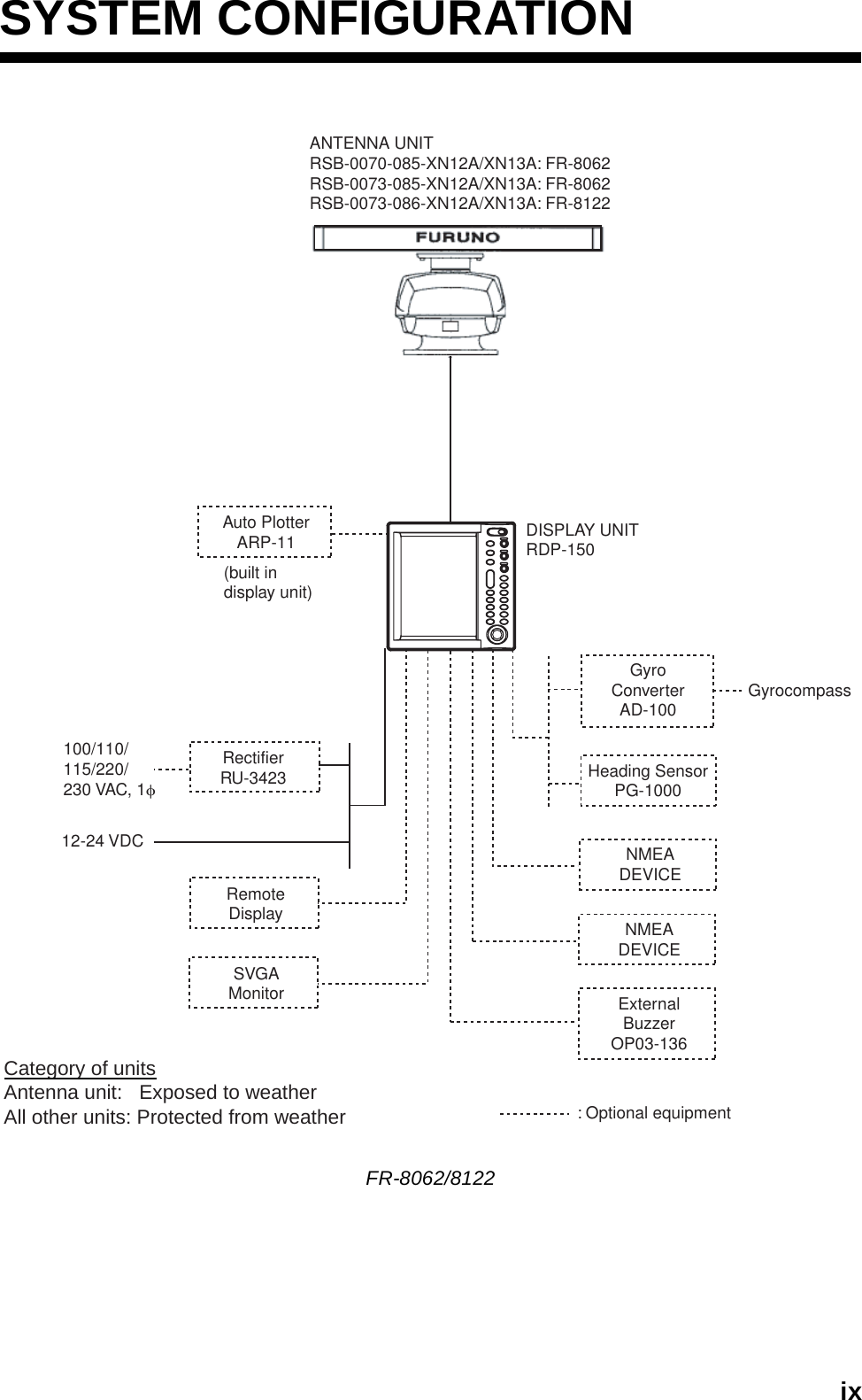
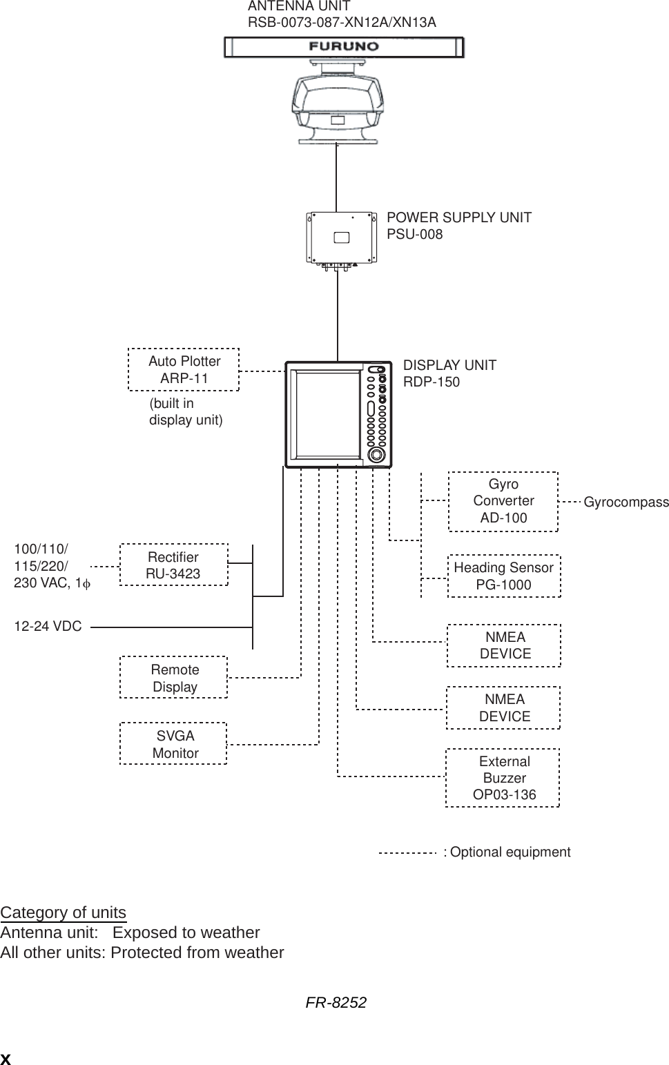
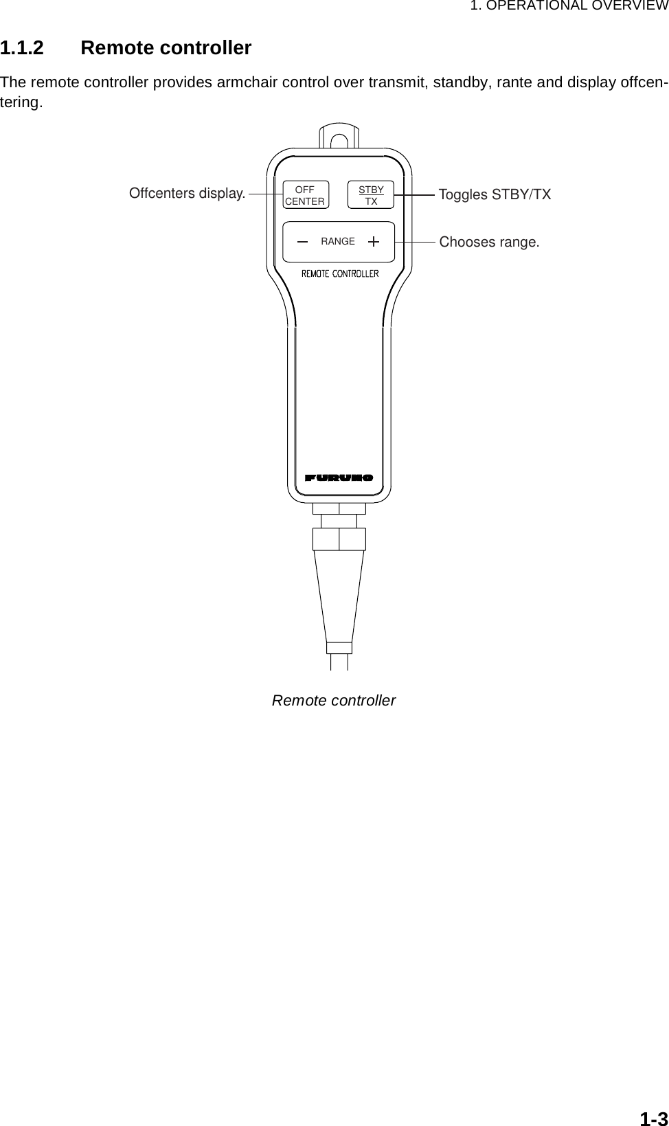
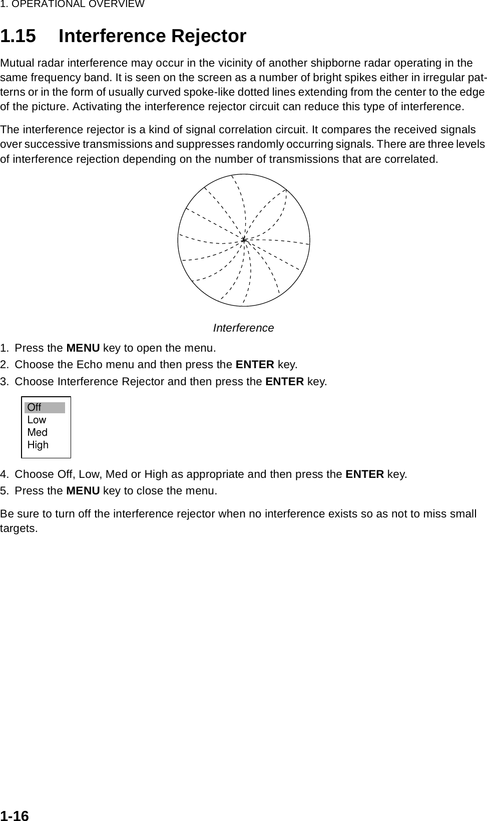
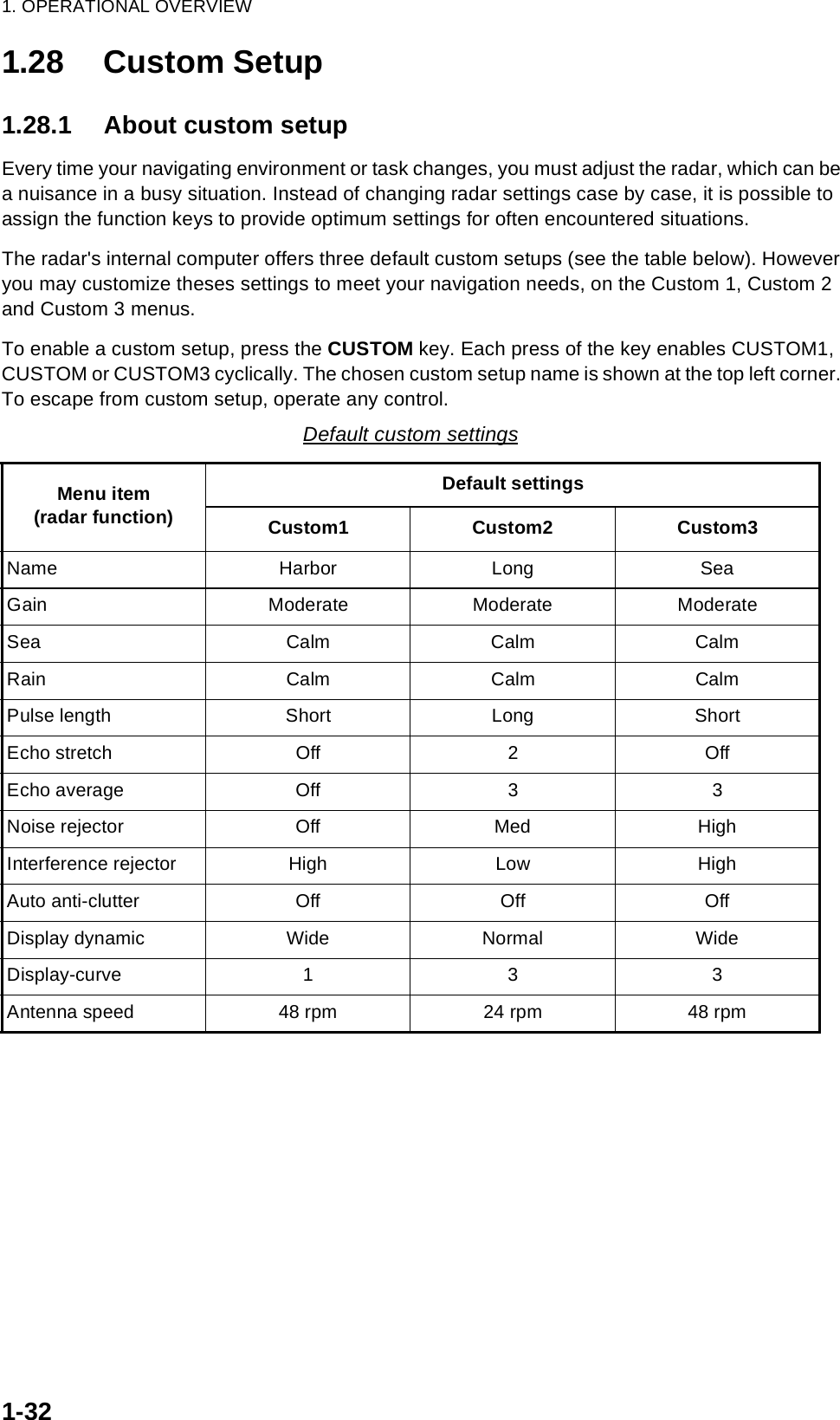
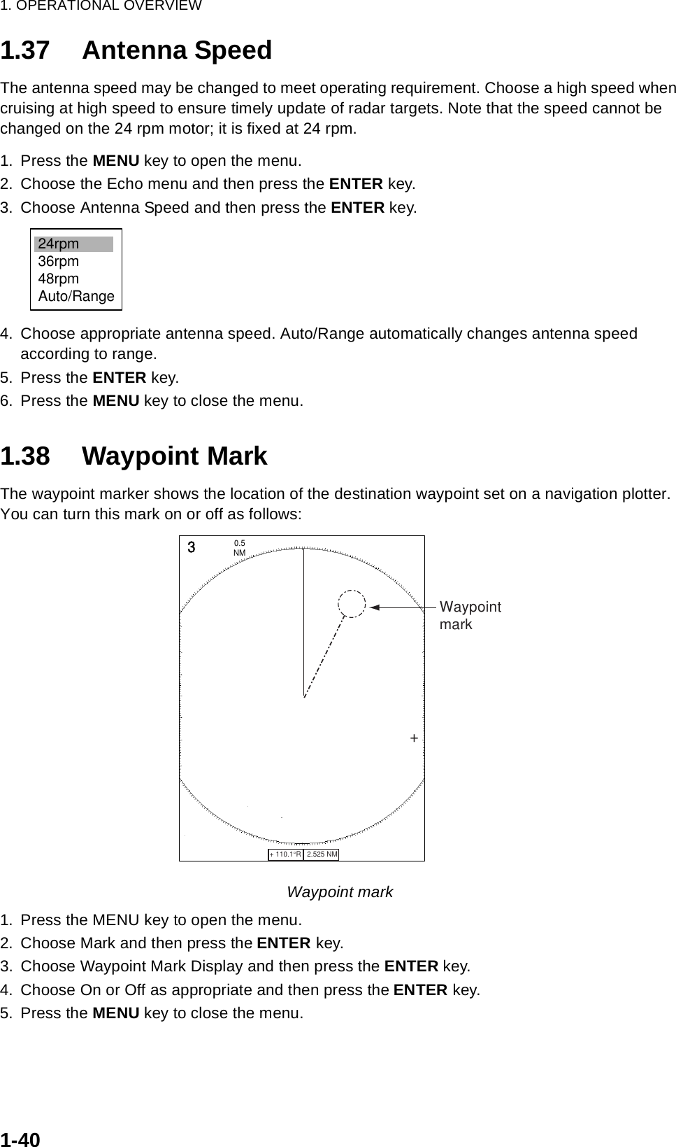
![1. OPERATIONAL OVERVIEW1-61.4 Display Brilliance, Panel DimmerThe display brilliance and panel dimmer may be adjusted as follows:1. Press the POWER/BRILL key momentarily to show the brilliance/panel dialog box.Brilliance/panel dimmer dialog box 2. Roll the trackball upward or downward to choose Brill or Panel, whichever you wish to adjust.3. Roll the trackball rightward or leftward to adjust. (You may also use the POWER/BRILL key.)4. Press the MENU key to close the window.1.5 Menu OverviewLess-often used functions are controlled through the menu, which consists of 14 menus and 3 sub menus. Use the trackball to choose item and option as below.1. Press the MENU key to display the menu.Menu2. Roll the trackball to choose a menu or sub menu. As you roll the trackball, the highlight in the Menu column indicates menu currently selected and the menu items change according to the menu selected.3. Press the ENTER key to enable operation from chosen menu. W Min Max X Brill (1 - 15) 9 9 Panel (1 - 7) 7 [ENTER]: Close STSystemGPSBrill/ColorEchoMarkTarget TrailsCustom 1 DisplayCustom 2Custom 3 TargetARPAISManual TuneAuto Rain TunePulse Length Auto Gain Auto Sea Echo StretchEcho Average:Auto:Short:1:Off:Rough:Calm:ModerateAuto Anti Clutter Display-DynamicDisplay-CurveNoise Rejector Interference Rejector 2nd Echo Rejector:Normal:1:Off::Off:OffMenuMenuEchoEchoMenusMenu itemsand optionsCurrently selected menuMenu locationindicatorS/T / W/X: Select[ENTER]: Enter [CANCEL/HL OFF]: Back[MENU]: Exit](https://usermanual.wiki/Furuno-USA/9ZWRTR087/User-Guide-589545-Page-17.png)
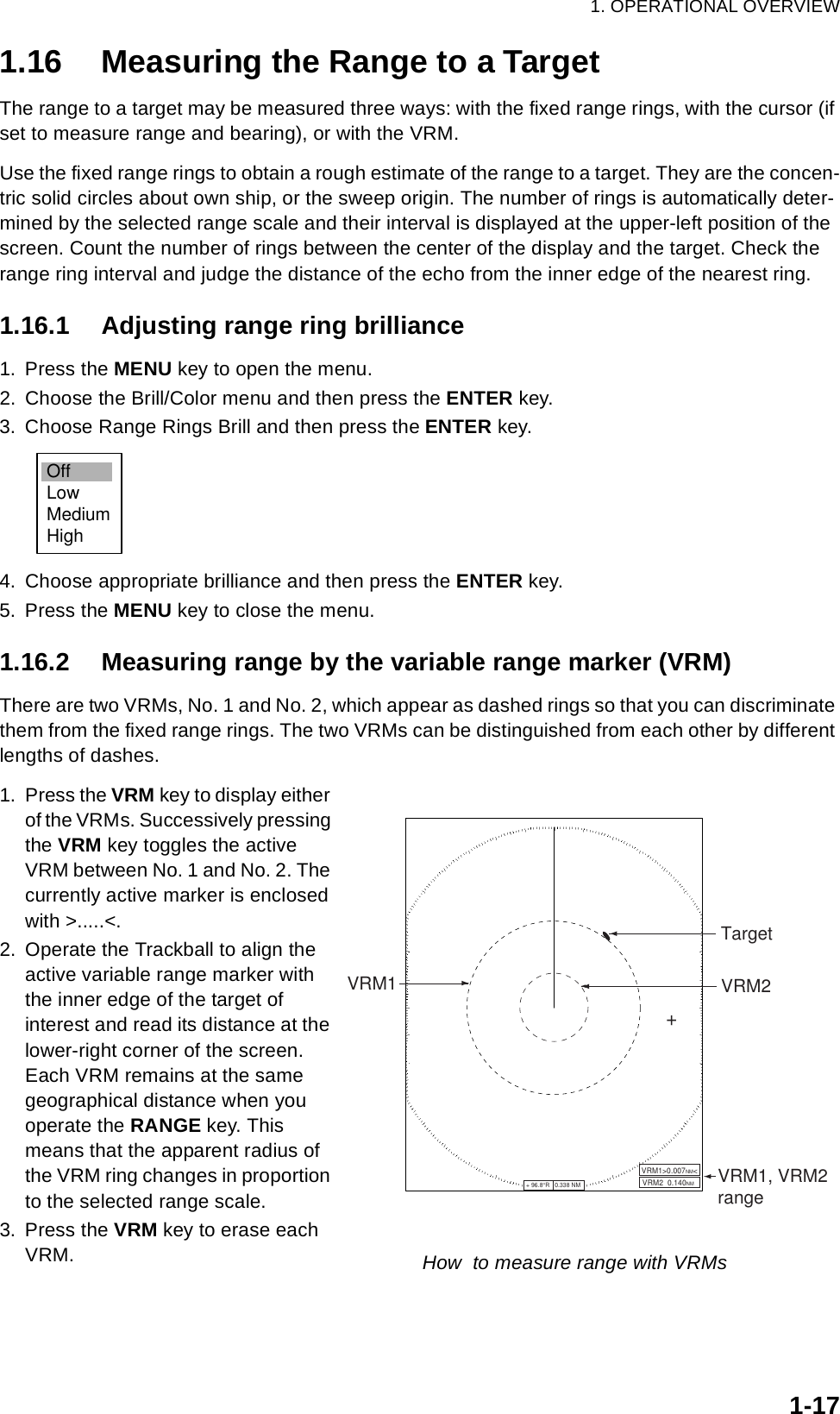
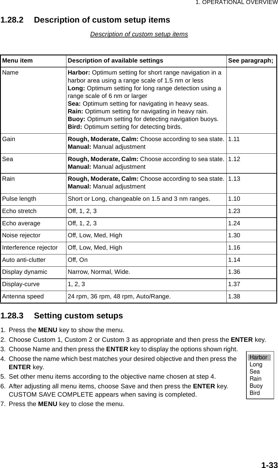
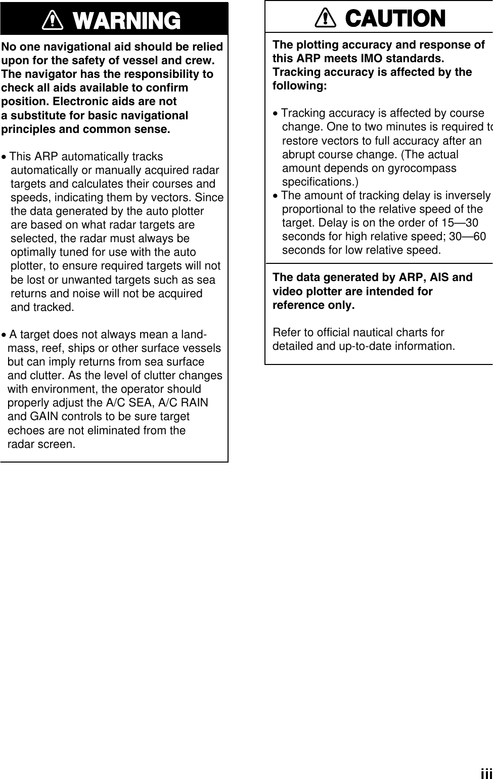
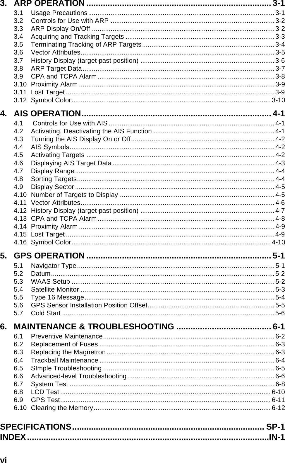
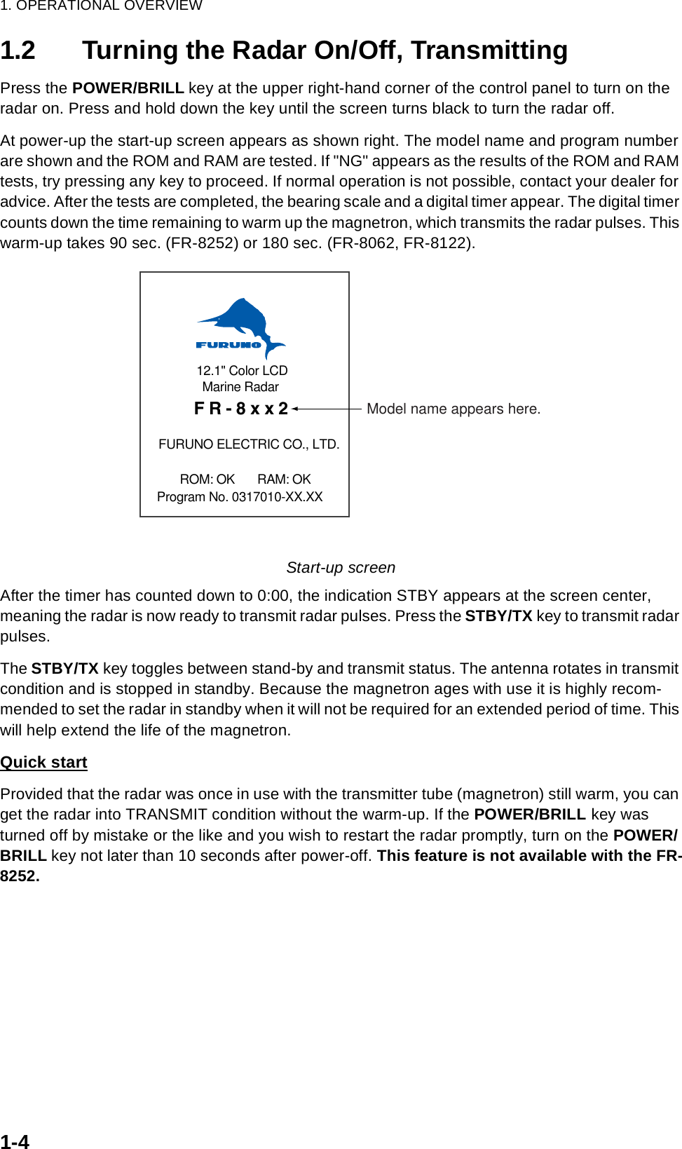
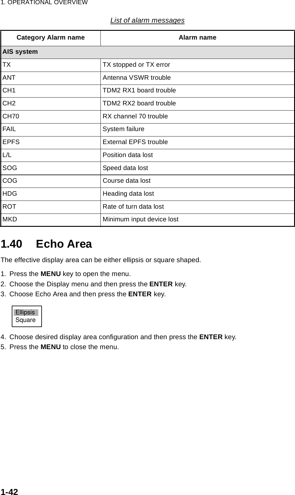
![1. OPERATIONAL OVERVIEW1-411.39 Alarm Message DisplayWhen a violation occurs the radar generates audible and visual alarms to alert you. The alarm message display shows all alarms currently violated. You may show this display as follows:1. Press the MENU key to open the menu.2. Choose the Display menu and then press the ENTER key.3. Choose Alarm Message and then press the ENTER key.Alarm message displayTo close the alarm message display, press any key.List of alarm messagesList of alarm messagesCategory Alarm name Alarm nameSignal missingHeading Heading signal lostBearing Antenna rotation signal lostPosition Position data lost Target AlarmTarget Alarm1 In (or Out) Echo has entered (or exited) target alarm zone 1.Target Alarm1 In (or Out) Echo has entered (or exited) target alarm zone 1ARP alarmCollision CPA and TCPA of an ARP target is less than preset CPA and TCPA.Lost Acquired ARP target becomes lostTarget-Full Target tracking capacity is reached.Proximity The range to an ARP target is less than the user-set proximity alarm range.AIS alarmCollision CPA and TCPA of an ARP target is less than preset CPA and TCPA.Proximity The range to an AIS target is less than the user-set proximity alarm range.[Signal Missing][Target Alarm1][ARP Alarm]<Please Push Any Key -- To Stop Alarm And Close this Window>](https://usermanual.wiki/Furuno-USA/9ZWRTR087/User-Guide-589545-Page-52.png)
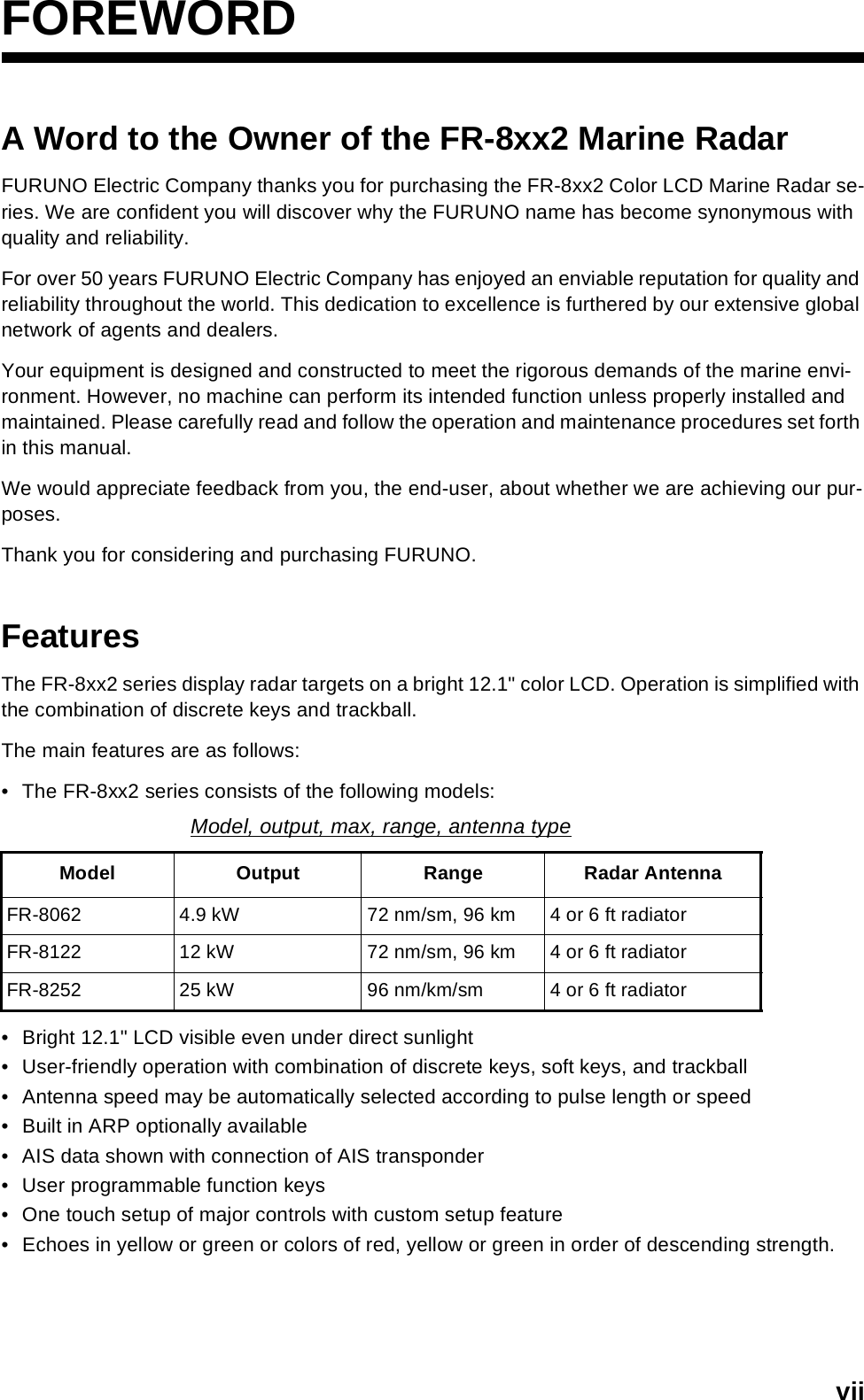
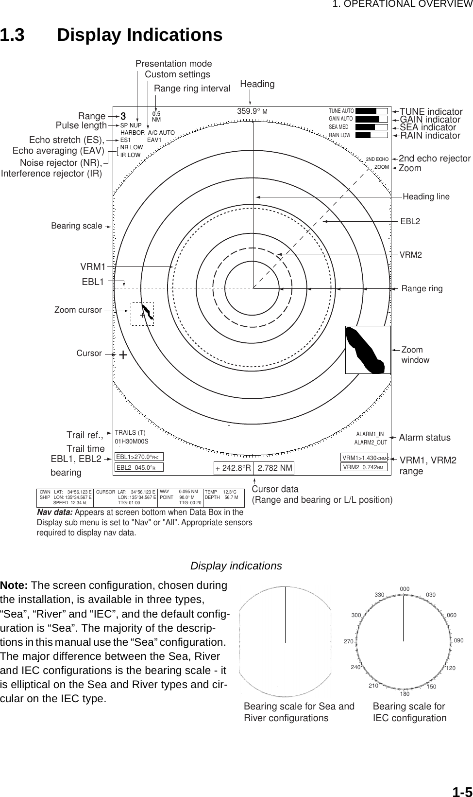
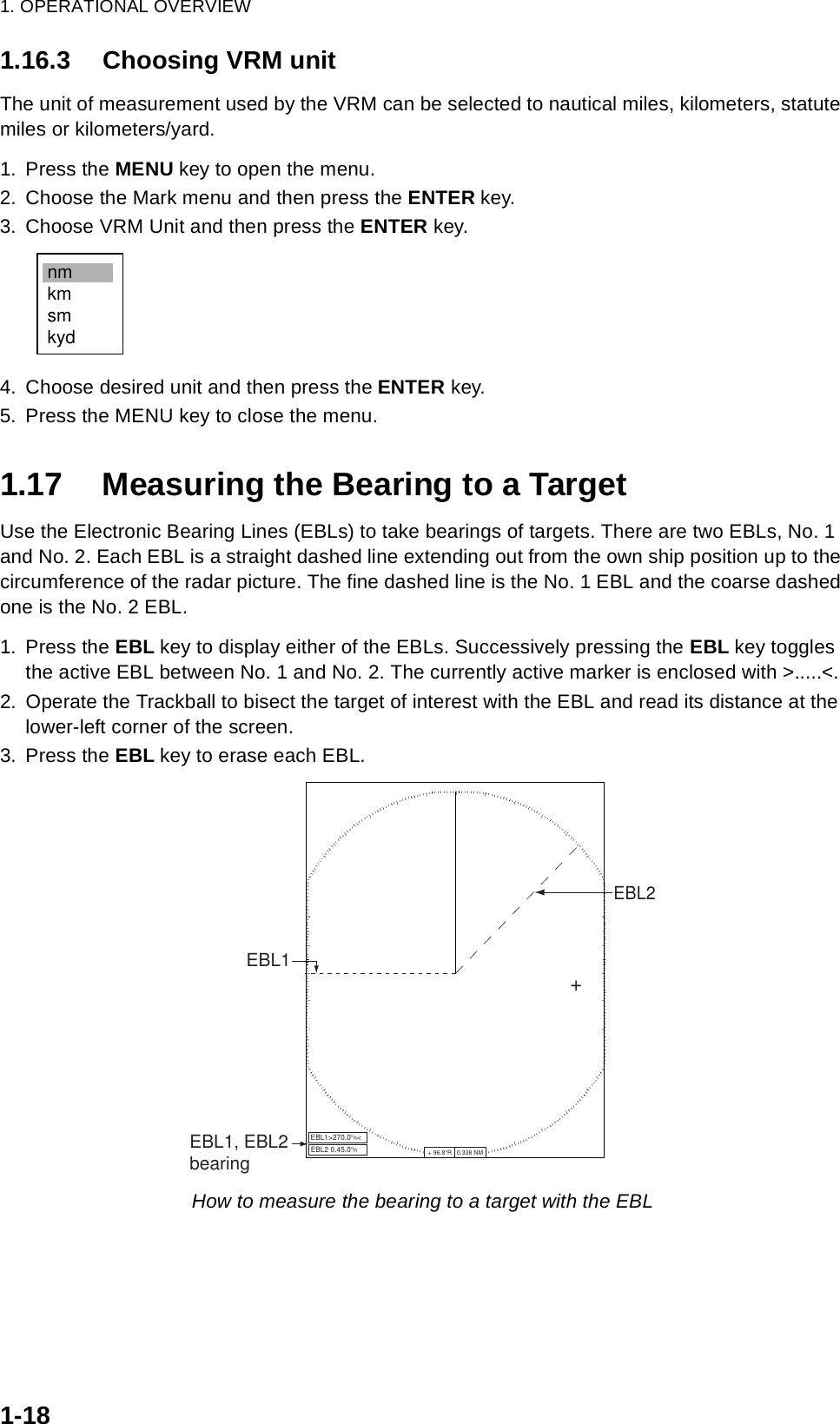
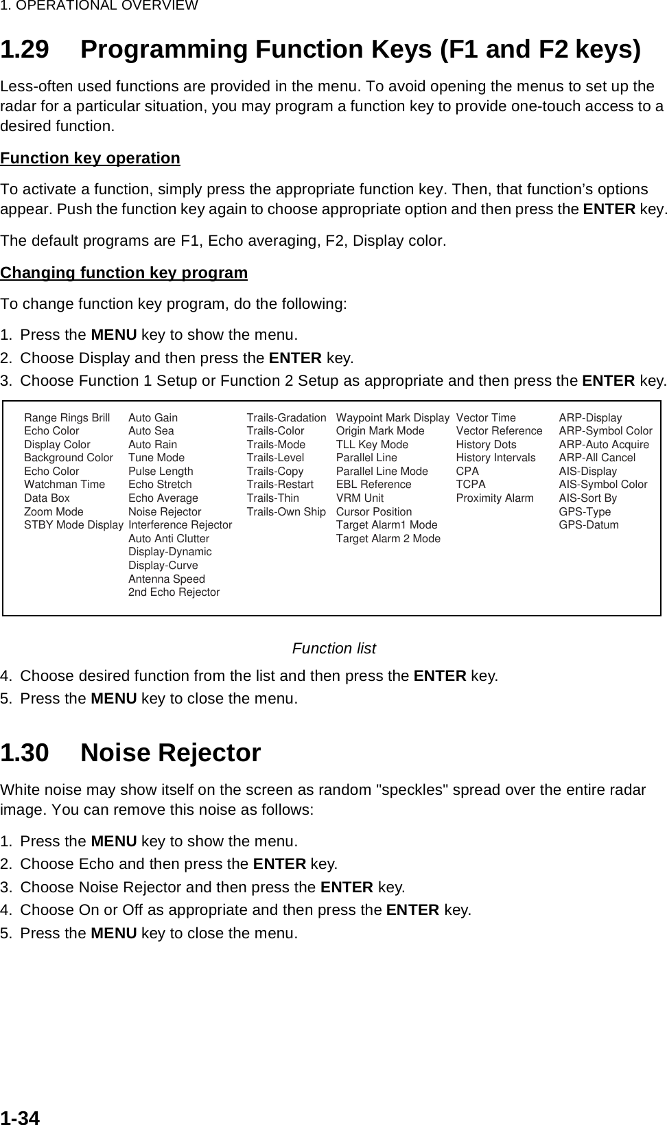
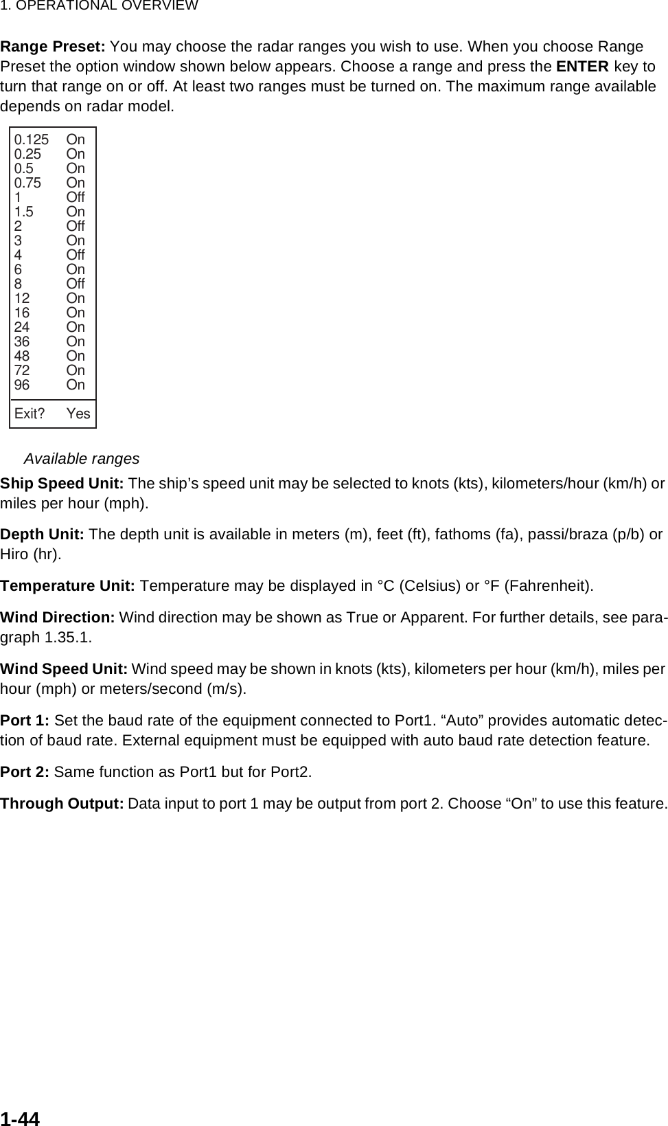
![1. OPERATIONAL OVERVIEW1-431.41 Customizing (Initial Menu)The Initial sub menu in the System menu contains items which allow you to customize your radar to meet your operational needs.1.41.1 Opening the Initial menu1. Press the MENU key to open the menu.2. Roll the trackball to choose System followed by Initial and then press the ENTER key.Initial menu1.41.2 Description of Initial menuKey Beep: A beep sounds when keys are pressed. You may turn this beep on or off.Range Unit: Range may be shown in nm, km or sm.Alarm Level: The target alarm may be set to sound against weak, medium or strong echoes.TX Antenna Rotate: Radar pulses may be transmitted without rotating the antenna. For the ser-vice technician.Max Shift Speed: Set the maximum shift speed to use with automatic offcentering. The setting range is 1-99 (kts)STBY Mode Display: STBY Mode Display sets the function of the radar in standby. “Normal” dis-plays “STBY” at the screen center; “Nav” displays navigation data, and “Economy” extinguishes the backlight of the LCD to conserve power.Bearing Source: Choose the type of bearing sensor connected to the radar; True (gyrocompass) or Magnetic (magnetic compass).S/T / W/X: Select[ENTER]: Enter [CANCEL/HL OFF]: Back[MENU]: ExitGPSBrill/ColorEchoMarkTarget TrailsCustom 1DisplayCustom 2Custom 3 TargetARPAISManual TuneMenuMenuInitialInitialSystemInitialFactoryInstallationKey Beep : OnRange Unit : nm Alarm Level : MedTX Antenna Rotate : RotateMax Shift Speed : 15 ktSTBY Mode Display : NormalBearing Source : MagneticRange PresetShip Speed Unit : ktDepth Unit : mTemperature Unit : °CWind Direction : ApparentWind Speed Unit : ktPort 1 Setup : AutoPort 2 Setup : Auto](https://usermanual.wiki/Furuno-USA/9ZWRTR087/User-Guide-589545-Page-54.png)
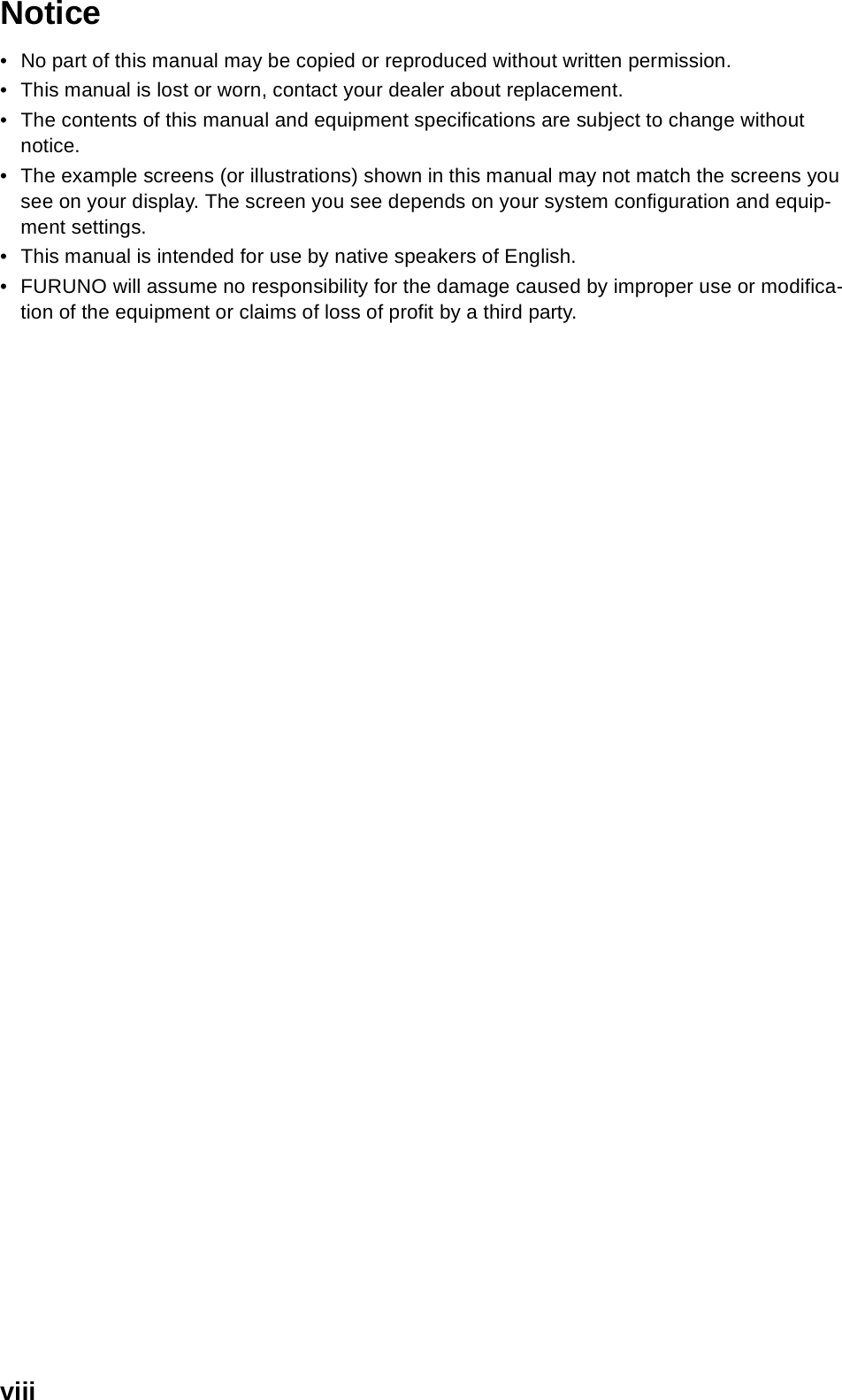
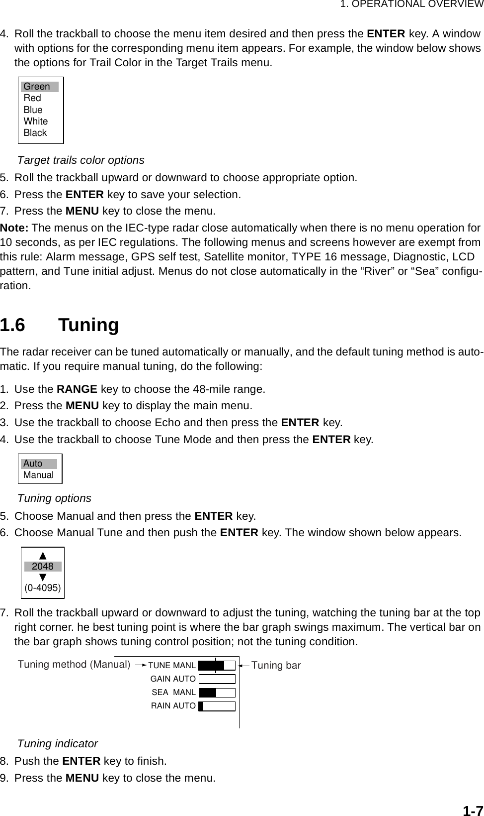
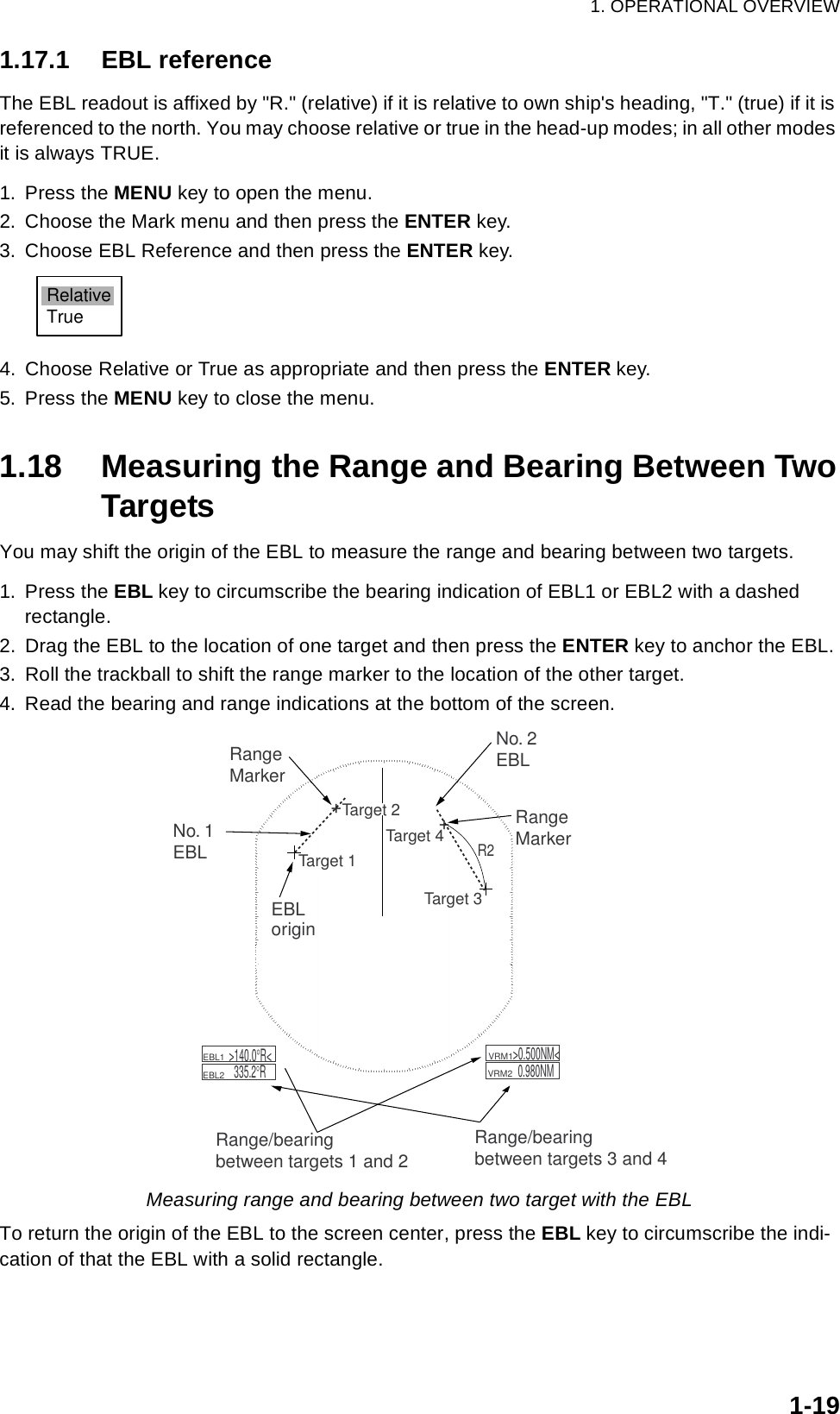
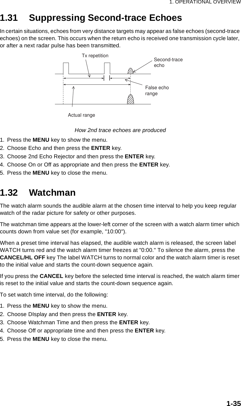
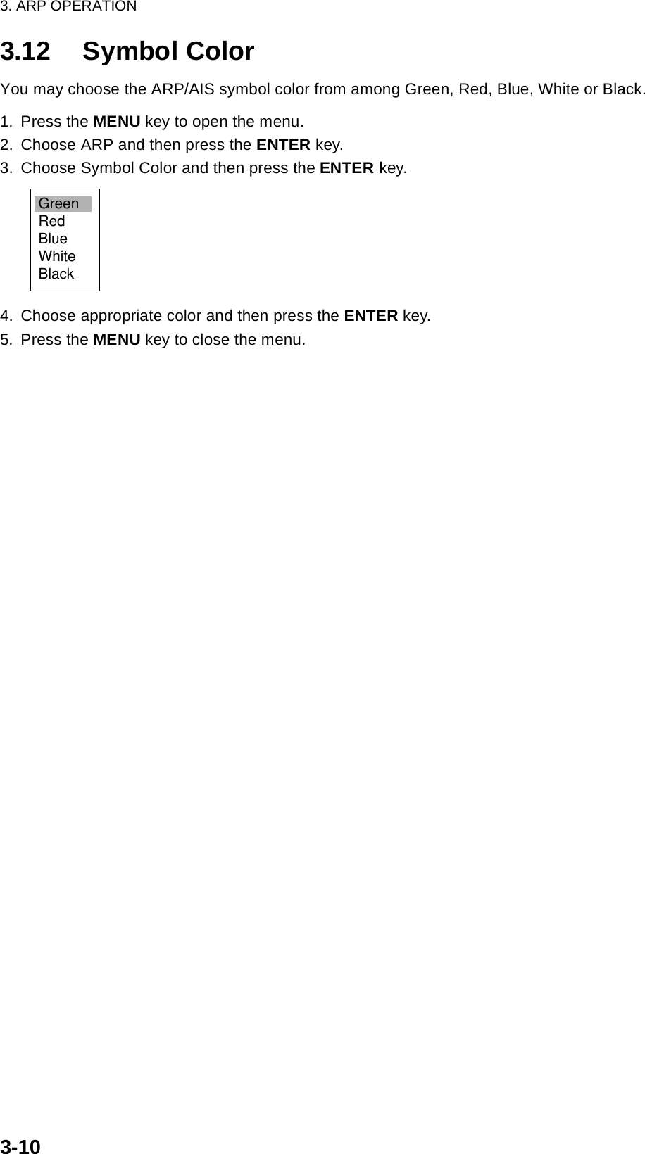
![3. ARP OPERATION3-23.2 Controls for Use with ARPENTER: Acquires cursor-selected target; Displays data for tracked target (in the data box at the bottom of the screen).CANCEL/HL OFF: Removes data of cursor-selected tracked target from the data box; stops tracking cursor-selected (when its data is not displayed in the data box.MENU: Accesses the Target and ARP menus for ARP operations.Trackball: Chooses target to acquire, cancel tracking or show target data.3.3 ARP Display On/OffYou may turn off the ARP display as shown below.1. Press the MENU key to display the main menu.2. Use the trackball to choose ARP and then press the ENTER key.ARP menu3. Use the trackball to choose Display and then press the ENTER key. 4. Choose Off or On as appropriate and then press the ENTER key.5. Press the MENU key to close the menu.GPSBrill/ColorEchoMarkTarget TrailsCustom 1DisplayCustom 2Custom 3 TargetARPAISManual TuneMenuMenuARPARPSystemDIsplay : OffSymbol Color : GreenAuto Acquire : OffAll Cancel : NoS/T / W/X: Select[ENTER]: Enter [CANCEL/HL OFF]: Back[MENU]: ExitOffOn](https://usermanual.wiki/Furuno-USA/9ZWRTR087/User-Guide-589545-Page-63.png)
![3. ARP OPERATION3-53.6 Vector AttributesWhat is a vector?A vector is a line extending from a tracked target which shows estimated speed and course of the target. The vector tip shows an estimated position of the target after the selected vector time elapses. It can be useful to extend the vector length (time) in order to evaluate the risk of collision with any target.VectorVector time, vector referenceVector time can be set to 30 seconds, 1, 3, 6, 15 or 30 minutes. You may reference the vectors to North (True, requires heading and speed data) or ship's heading (relative) as desired. 1. Press the MENU key to open the menu.2. Choose Target and then press the ENTER key.Target menu3. Choose Vector Time and then press the ENTER key.4. Choose desired vector time and then press the ENTER key.5. Choose Vector Reference and then press the ENTER key.6. Choose Relative or True as appropriate and then press the ENTER key.7. Press the MENU key to close the menu.Note: The functions of the Target menu are commonly shared by ARP and AIS.VectorGPSBrill/ColorEchoMarkTarget TrailsCustom 1DisplayCustom 2Custom 3 TargetARPAISManual TuneMenuMenuTargetTargetSystemVector Time : 6 minVector Reference : RelativeHistory Dots : 5History Intervals : 1 minCPA : 1 nmTCPA : 1 minProximity Alarm : OffS/T / W/X: Select[ENTER]: Enter [CANCEL/HL OFF]: Back[MENU]: Exit30sec1min3min6min15min30minRelativeTrueVector time choicesVector reference choices](https://usermanual.wiki/Furuno-USA/9ZWRTR087/User-Guide-589545-Page-66.png)
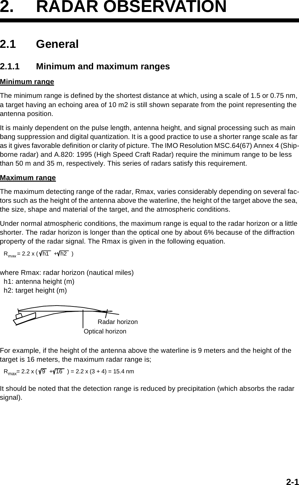
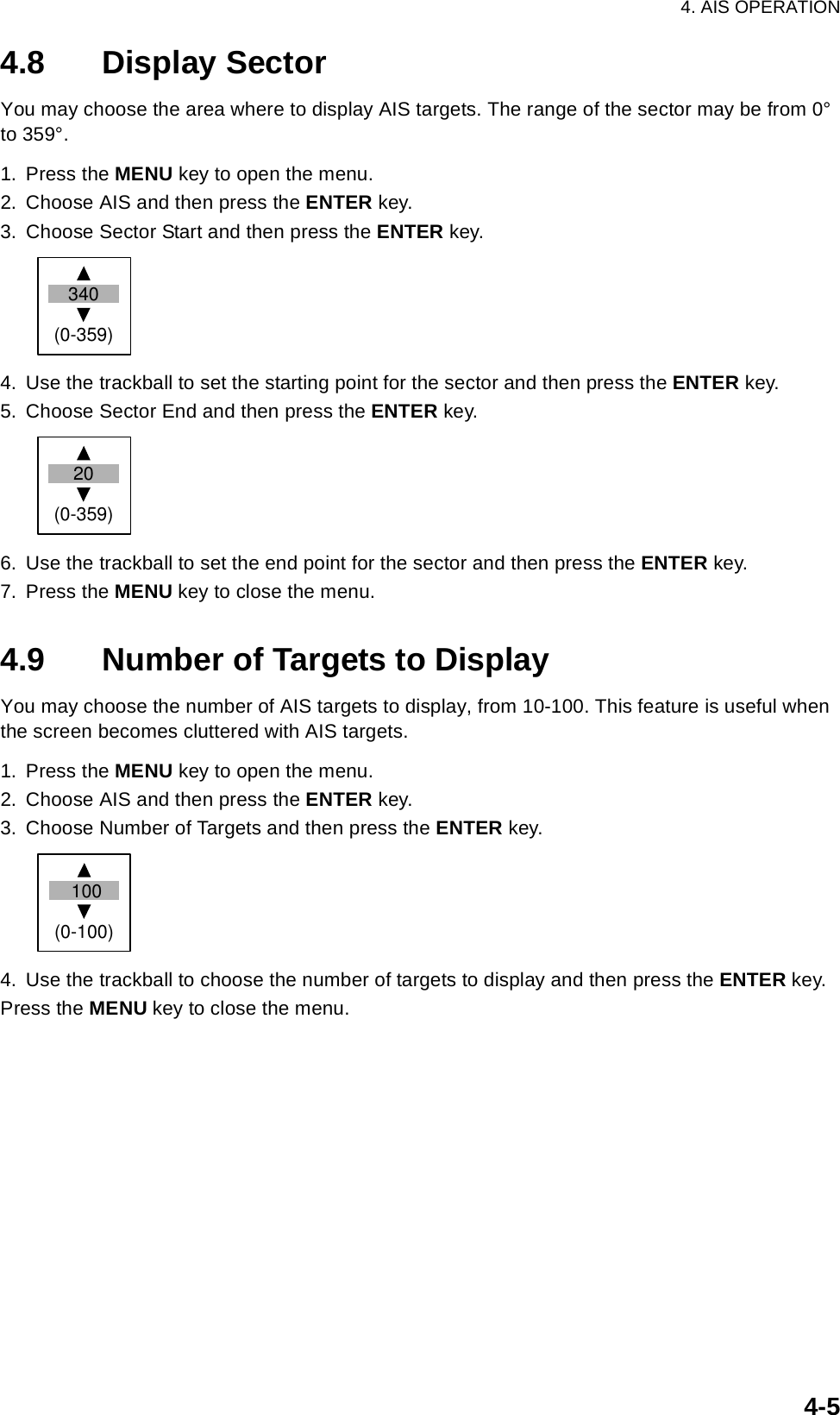
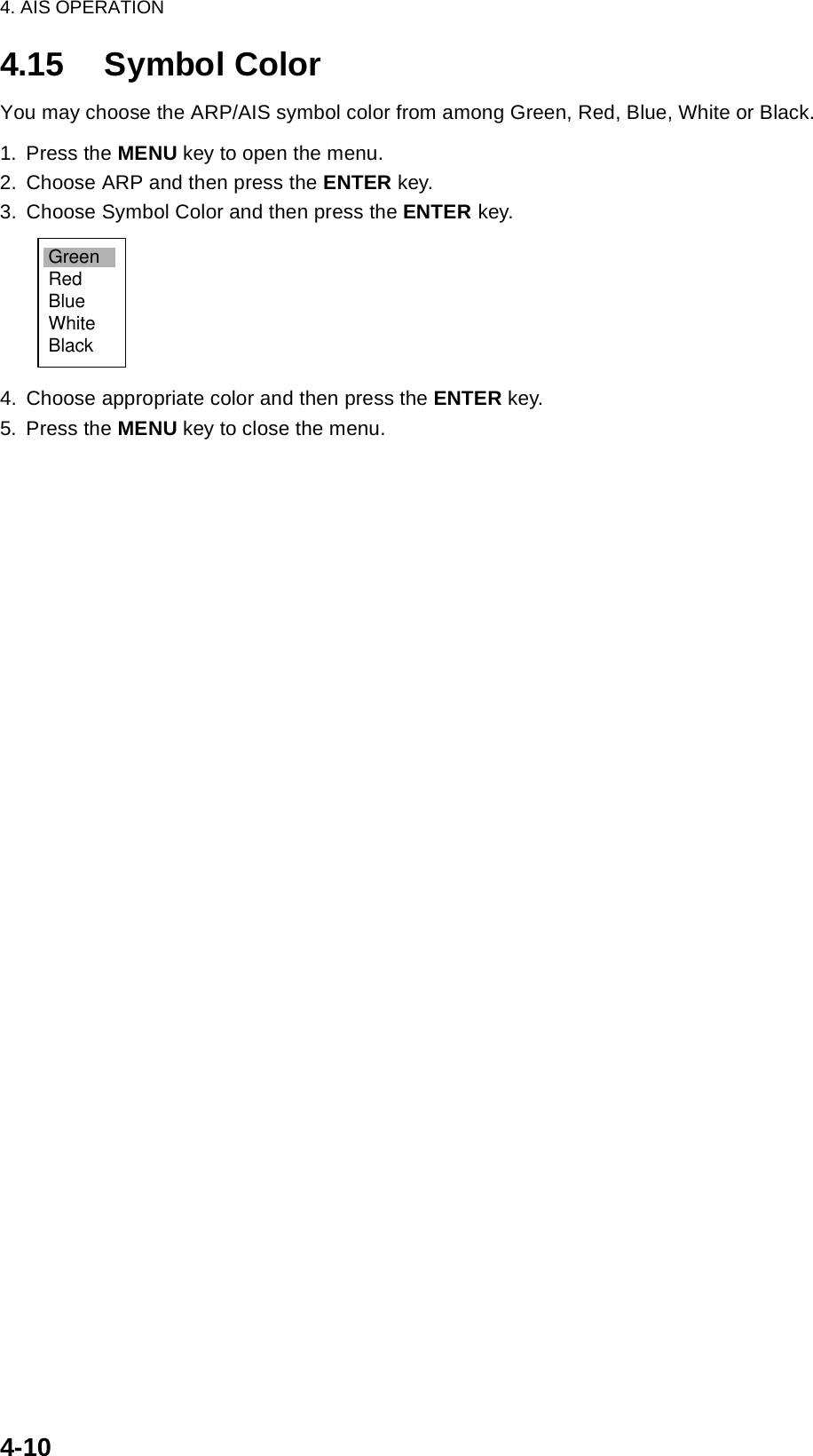
![4-14. AIS OPERATIONConnected to an AIS Transponder via an AIS Interface, the FR-8xx2 series can show the name, position and other nav data of the nearest 100 AIS transponder-equipped ships. This radar accepts position data fixed by WGS-84 geodetic datum. Set the datum to WGS-84 on the GPS navigator connected to this radar. If other type of datum is input, the error message "DATUM" appears and the AIS feature is inoperative.4.1 Controls for Use with AISENTER: Displays data for cursor-selected active AIS target (in the data box at the bottom of the screen).CANCEL/HL OFF: Removes data of cursor-selected AIS target from the data box.MENU: Accesses the Target and AIS menus for AIS operations.Trackball: Chooses active target to display its data.4.2 Turning the AIS Display On or OffYou may turn the AIS display on or off. The system continues processing of AIS targets regardless of whether the AIS display is on or off, provided it has been activated.1. Press the MENU key to display the main menu.2. Choose AIS and then press the ENTER key.AIS menu3. Choose DIsplay and then press the ENTER key. 4. Choose Off or On as appropriate and then press the ENTER key.5. Press the MENU key to close the menu.GPSBrill/ColorEchoMarkTarget TrailsCustom 1DisplayCustom 2Custom 3 TargetARPAISManual TuneMenuMenuAISAISSystemDisplay : OffSymbol Color : GreenRange : 3.0nmSector Start : 340Sector End : 20Sort By : RangeNumber of Target : 100S/T / W/X: Select[ENTER]: Enter [CANCEL/HL OFF]: Back[MENU]: Exit](https://usermanual.wiki/Furuno-USA/9ZWRTR087/User-Guide-589545-Page-72.png)
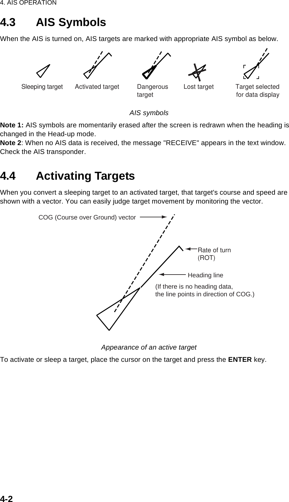
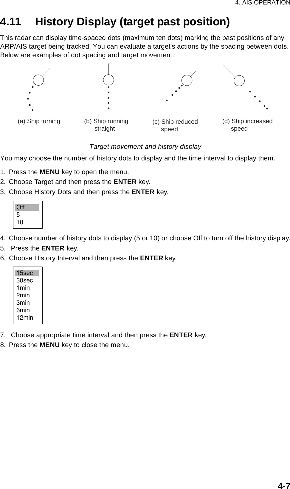
![4. AIS OPERATION4-64.10 Vector AttributesWhat is a vector?A vector is a line extending from a tracked target which shows estimated course of the AIS target. The vector tip shows an estimated position of the target after the selected vector time elapses. It can be useful to extend the vector length (time) in order to evaluate the risk of collision with any target. (See the illustration on page 4-2 for the appearance of a vector.)Vector time, vector referenceVector time can be set to 30 seconds, 1, 3, 6, 15 or 30 minutes. You may reference the vectors to North (True, requires heading and speed data) or ship's heading (relative) as desired. 1. Press the MENU key to open the menu.2. Choose Target and then press the ENTER key.Target menu3. Choose Vector Time and then press the ENTER key.4. Choose desired vector time and then press the ENTER key.5. Choose Vector Reference and then press the ENTER key.6. Choose Relative or True as appropriate and then press the ENTER key.7. Press the MENU key to close the menu.GPSBrill/ColorEchoMarkTarget TrailsCustom 1DisplayCustom 2Custom 3 TargetARPAISManual TuneMenuMenuTargetTargetSystemVector Time : 6 minVector Reference : RelativeHistory Dots : 5History Intervals : 1 minCPA : 1 nmTCPA : 1 minProximity Alarm : OffS/T / W/X: Select[ENTER]: Enter [CANCEL/HL OFF]: Back[MENU]: Exit30sec1min3min6min15min30minRelativeTrueVector time choicesVector reference choices](https://usermanual.wiki/Furuno-USA/9ZWRTR087/User-Guide-589545-Page-77.png)
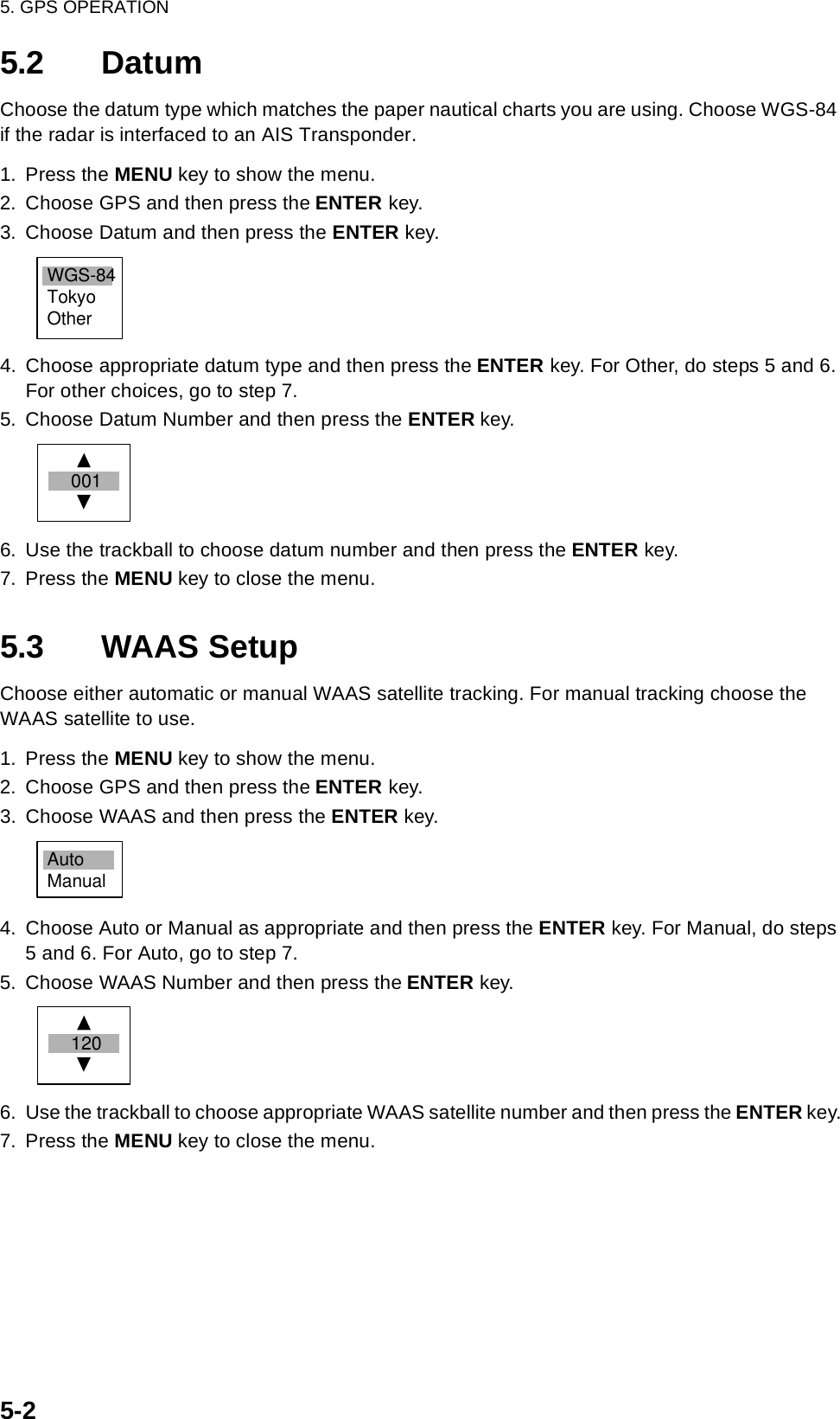
![5-15. GPS OPERATIONWith connection of a FURUNO GPS navigator, you may set up the GPS navigator from this radar.5.1 Navigator Type1. Press the MENU key to show the menu.2. Choose GPS and then press the ENTER key.GPS menu3. Choose Type and then press the ENTER key.4. Choose type of navigator connected to this radar and then press the ENTER key.5. Press the MENU key to close the menu.GPSBrill/ColorEchoMarkTarget TrailsCustom 1DisplayCustom 2Custom 3 TargetARPAISManual TuneMenuMenuGPSGPSSystemType : WAASDatum : WGS-84Datum Number : 001WAAS : AutoWAAS Number : 120GPS Self TestSatellite MonitorType 16 MessageForward Offset : 0Right Offset : 0Cold StartS/T / W/X: Select[ENTER]: Enter [CANCEL/HL OFF]: Back[MENU]: ExitGPSWAASDGPS](https://usermanual.wiki/Furuno-USA/9ZWRTR087/User-Guide-589545-Page-82.png)
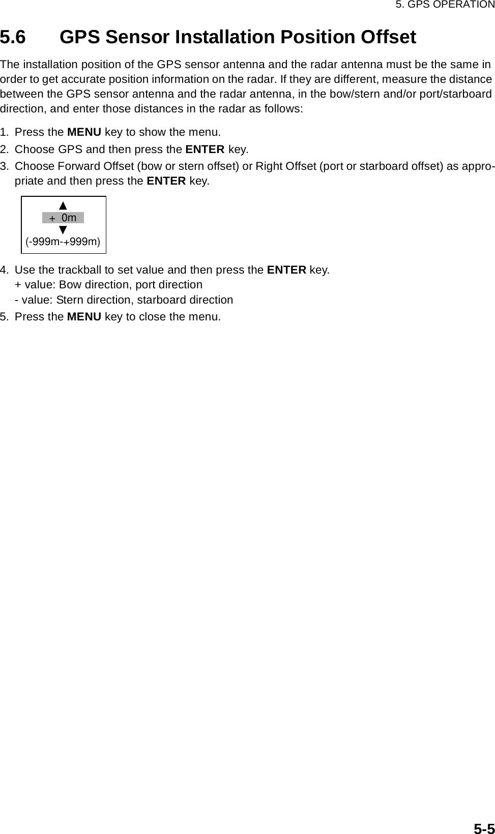
![5. GPS OPERATION5-35.4 Satellite MonitorThe Satellite Monitor provides comprehensive information about GPS and WAAS satellites. For more detailed information, see your GPS navigator’s owner’s manual.1. Press the MENU key to show the menu.2. Choose GPS and then press the ENTER key.3. Choose Satellite Monitor and then press the ENTER key.Satellite monitorTo close only the satellite monitor display, press the ENTER key.D3D DOP1.585mSatellite MonitorDGPS StatusStation HealthDGPS DataSignal StrengthSignal SNROKOK10dB11dB13Altitude01GPSWAAS122416SNRSatellite30 40 50122013118190607090813Satellite Monitor161301 0619180907 08311224BearingdisplayDOP (Dilution of Precision, 0-99.0)SNR of tracked GPS satellitesSatellites whose SNR is above40 are used to fix position.GPS mode2D, 3D, D2DD3D, W2DW3D, DOPGPS satelliteno.WAASsatelliteSatellites in ring have elevationangle of 5°Satellites in ring have elevationangle of 45°OK or NG (No Good) displayedOK or NG (No Good) displayed 0-99 db, higher the better 0-99 db, higher the betterSatellitealtitudeWAAS satelliteWN[MENU]: Close MENU [ENTER]: Close this window](https://usermanual.wiki/Furuno-USA/9ZWRTR087/User-Guide-589545-Page-84.png)
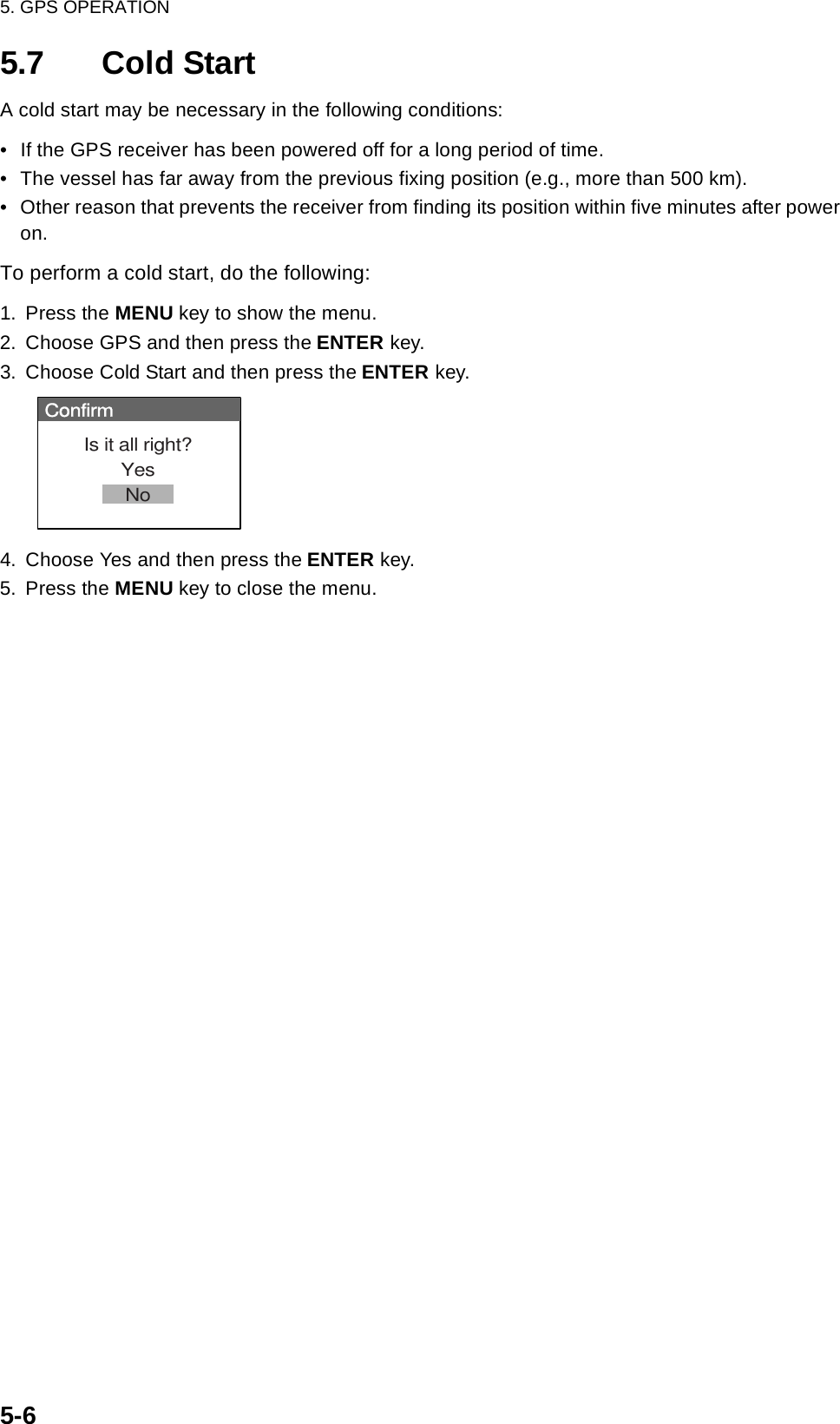
![5. GPS OPERATION5-45.5 Type 16 MessageThe type 16 message provides weather information. It is transmitted by the Japan Maritime Safety Agency, thus you must be within the transmitting range of a japanese DGPS reference station to receive this type of message.You may display this type of message as follows:1. Press the MENU key to show the menu.2. Choose GPS and then press the ENTER key.3. Choose Type 16 Message and then press the ENTER key. (If no messages are present you cannot choose this menu item.) Type 16 messageWeather messages from as many as six DPGS reference stations are shown and the latest is at the top.The oldest message is erased when a new message arrives.To close only the message board, press the ENTER key.Type 16 MessageType 16 MessagePoint Name Time Wind Pressure WaveDirection/SpeedMurotasakiKobeOsakakoOsekiTomgashimaShinomisaki13:2513:5513:4513:1513:5013:5513:3513:0513:3013:00ENENENWNNNWSSWSNWW5m10m5m10m5m10m5m10m5m10m1015hPa1016hPa1015hPa1017hPa1017hPa1017hPa1013hPa1015hPa1015hPa1016hPa10m13m11m10m9m10m8m9m5m10m13:3013:00 NWW5m10m 1015hPa1016hPa 5m10m[MENU]: Close MENU [ENTER]: Close this windowName of DGPSreference stationTimeWind directionand speed(16 compass pts.)Atmosphericpressure (0-9999 hPa)Wave height(0-99 m)](https://usermanual.wiki/Furuno-USA/9ZWRTR087/User-Guide-589545-Page-85.png)
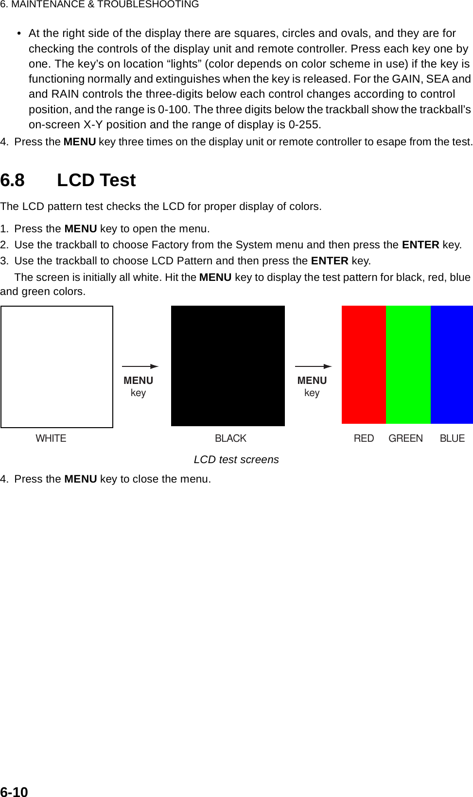
![6. MAINTENANCE & TROUBLESHOOTING6-86.7 System TestThe diagnostic test checks the system for proper operation.1. Press the MENU key to open the menu.2. Use the trackball to choose Factory from the System menu and then press the ENTER key.Factory menuGPSBrill/ColorEchoMarkTarget TrailsCustom 1DisplayCustom 2Custom 3 TargetARPAISManual TuneSystemInitialFactoryInstallationTestLCD PatternMemory ClearMenuMenuFactoryFactoryS/T / W/X: Select[ENTER]: Enter [CANCEL/HL OFF]: Back[MENU]: Exit](https://usermanual.wiki/Furuno-USA/9ZWRTR087/User-Guide-589545-Page-95.png)
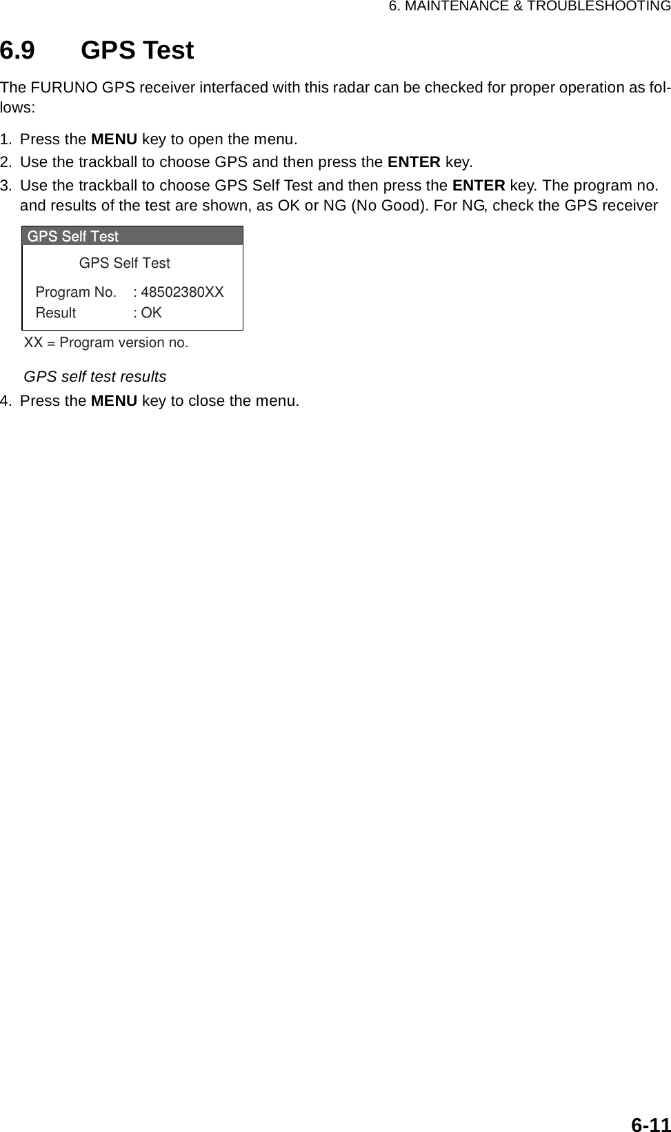
![6. MAINTENANCE & TROUBLESHOOTING6-93. Use the trackball to choose Test and then press the ENTER key.DIagnostics screen• At the top of the screen the results of system checks are displayed. OK or NG (No Good) is shown as the result for the check of ROM, RAM, data ports NMEA1 and NMEA2 (blank if no data is input) and RS-232C. For any NG contact your dealer for advice. PROGRAM NUMBER shows program number and program version number.• Heading and bearing signals are checked for proper input and the result displayed as OK or NG. Tune and indicator voltages, antenna rotation speed, antenna motor voltage, echo level and trigger frequency are measured and shown. TOTAL ON TIME and TOTAL TX TIME show the total number of hours the radar has been powered and trans-mitted, respectively.• The INPUT NMEA window shows all the NMEA sentences being input to this radar. • If the optional ARP-11 is connected, its program number and test results are shown below the INPUT NMEA window.INPUT NMEAROM : OKRAM : OKNMEA1 : OKNMEA2 : OKRS-232C : OKPROGRAM NUMBER : 0317101-XX.XXHEADING : OKBEARING : OKTUNE VOLTAGE : 10.1 VINDICATOR VOLTAGE : 4.2 VANTENNA ROTATION : 48.1 rmpMOTOR VOLTAGE : 23.4 VECHO LEVEL : -40 dBmTRIGGER FREQUENCY : 3000 HzTOTAL ON TIME : 123456.7 HTOTAL TX TIME : 987654.3 HInput NMEA data sentences appear here.ARP-11 PROGRAM NUMBER: 035-1515-XX.XXARP-11 : OK[MENU] x 3 : Exit<REMOTE CONTROLLER>000000000000000](https://usermanual.wiki/Furuno-USA/9ZWRTR087/User-Guide-589545-Page-96.png)