Furuno USA 9ZWRTR088A Marine Radar User Manual Cover
Furuno USA Inc Marine Radar Cover
UserManual.wiki
>
Furuno USA
>
9ZWRTR088A User Manual
>
op man part 1
Contents
1.
inst manual
2.
op man part 1
3.
op man part 2
4.
op man part 3
op man part 1
Navigation menu
Upload a User Manual
Namespaces
Wiki Guide
HTML
PDF
Info
Views
User Manual
Discussion / Help
Navigation
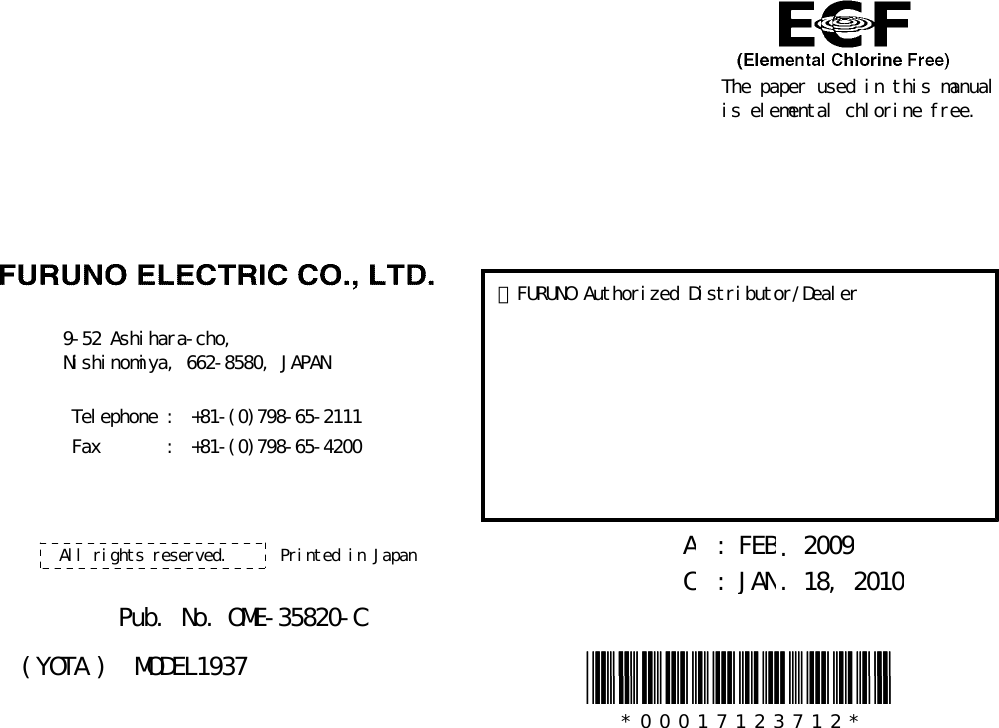
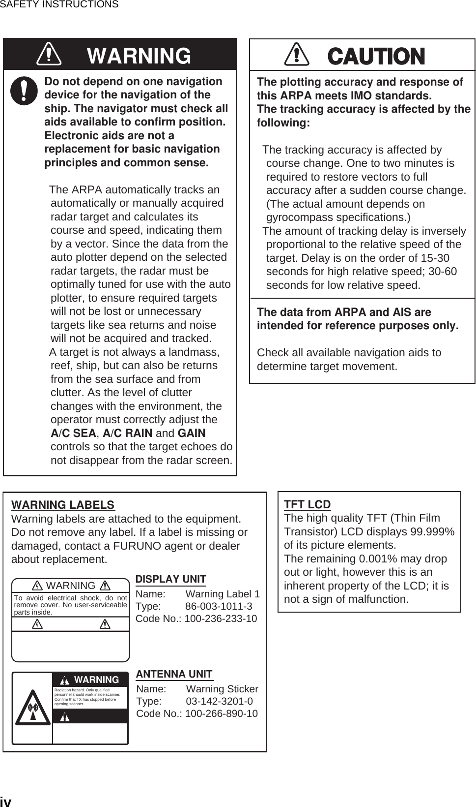
![ii SAFETY INSTRUCTIONSWARNINGModel Distance to100 W/m2 pointWARNINGIndicates a condition that can cause death or serious injury if not avoided.CAUTIONIndicates a condition that can cause minor or moderate injury if not avoided. Warning, Caution Mandatory ActionProhibitive ActionRead these safety instructions before you operate the equipment. Distance to50 W/m2 point1937 0.1 mRadio Frequency Radiation HazardThe radar antenna sends the electromagnetic radio frequency (RF) energy. This energy can be dangerous to you, especially your eyes. Do not look at the radiator or near the antenna when the antenna is rotating.The distances at which RF radiation levels of 100 W/m2, 50 W/m2 and 10 W/m2 exist are shown in the table.Note: If the antenna unit is installed at a close distance in front of the wheel house,prevent the transmission in that area to protect passengers and crew from microwaveradiation. Set the [Sector Blanks] in the [System] menu.Distance to10 W/m2 point0.9 m](https://usermanual.wiki/Furuno-USA/9ZWRTR088A.op-man-part-1/User-Guide-1456393-Page-4.png)
![TABLE OF CONTENTSvi1.24.7 How to restart, stop the trails .......................................................................1-331.24.8 Narrow trails.................................................................................................1-341.24.9 Your ship trail ............................................................................................... 1-341.25 How to Send the Target Position and Enter the Origin Mark ...................................1-341.26 How to Hide the Heading Line Temporarily ............................................................. 1-351.27 Presentation Brilliance ............................................................................................. 1-351.28 Custom Setup .......................................................................................................... 1-361.28.1 About custom setup .....................................................................................1-361.28.2 Description of custom setup items ............................................................... 1-361.28.3 How to set custom setups............................................................................ 1-371.29 How to Program Function Keys (F1, F2 and F3 keys)............................................. 1-381.30 Noise Rejector..........................................................................................................1-391.31 Wiper........................................................................................................................1-391.32 How to Reduce Second-trace Echoes .....................................................................1-401.33 Watchman................................................................................................................ 1-401.34 Color Selections....................................................................................................... 1-411.34.1 Preset colors ................................................................................................ 1-411.34.2 Custom colors .............................................................................................. 1-421.35 Navigation Data........................................................................................................ 1-431.35.1 Navigation data during standby.................................................................... 1-431.35.2 Navigation data at the bottom of the screen ................................................1-431.36 Dynamic Range........................................................................................................1-441.37 Characteristics Curve............................................................................................... 1-451.38 Waypoint Marker ......................................................................................................1-461.39 Alarm Message ........................................................................................................1-461.40 Echo Area ................................................................................................................1-481.41 Initial Sub Menu .......................................................................................................1-491.41.1 How to open the Initial sub menu.................................................................1-491.41.2 Description of Initial sub menu..................................................................... 1-491.42 Units Sub Menu........................................................................................................1-511.43 Sector Blank.............................................................................................................1-511.44 Other Menu Items .................................................................................................... 1-531.44.1 Menu items on the [Brill/Color] menu...........................................................1-531.44.2 Menu items on the [Display] menu...............................................................1-551.44.3 Menu items on the [Echo] menu ..................................................................1-561.45 Remote Display........................................................................................................ 1-562. DESCRIPTION OF RADAR...................................................................................2-12.1 General ......................................................................................................................2-12.1.1 Minimum and maximum ranges.....................................................................2-12.1.2 Radar resolution.............................................................................................2-22.1.3 Bearing accuracy ........................................................................................... 2-32.1.4 Range measurement......................................................................................2-32.2 False Echoes ............................................................................................................. 2-32.2.1 Multiple echoes .............................................................................................. 2-32.2.2 Sidelobe echoes............................................................................................. 2-42.2.3 Virtual image .................................................................................................. 2-42.2.4 Shadow sector ...............................................................................................2-52.3 SART (Search and Rescue Transponder) .................................................................2-62.3.1 SART description ........................................................................................... 2-62.3.2 General remarks on receiving SART ............................................................. 2-72.4 RACON ...................................................................................................................... 2-8](https://usermanual.wiki/Furuno-USA/9ZWRTR088A.op-man-part-1/User-Guide-1456393-Page-8.png)

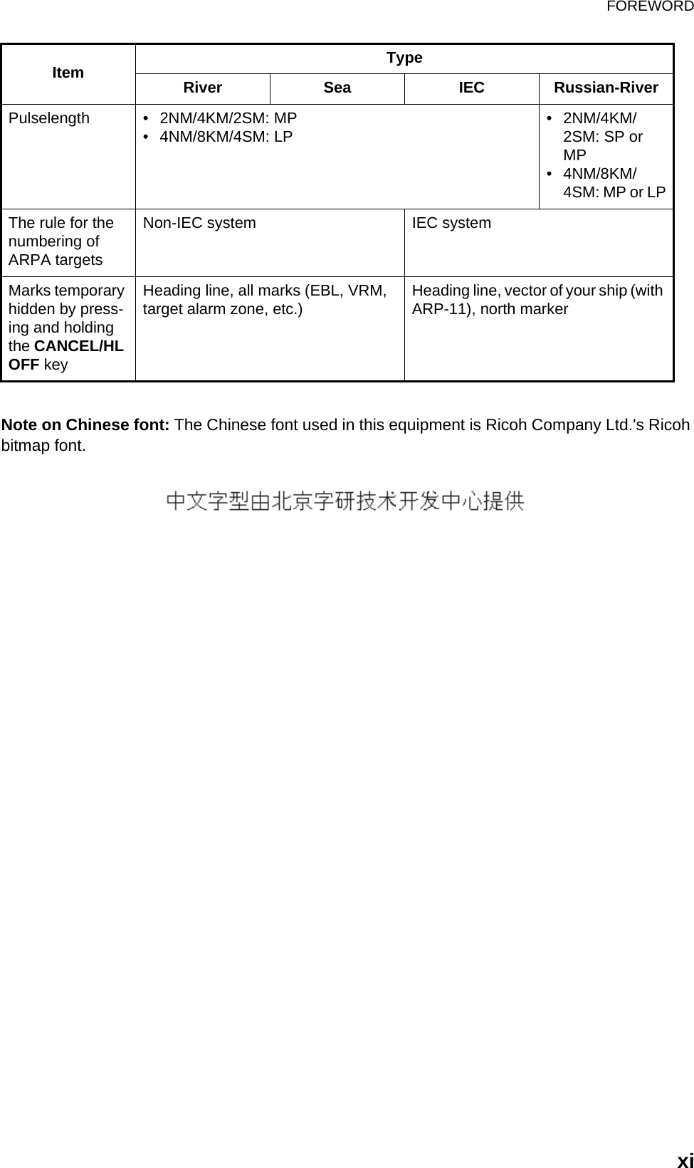
![FOREWORDxRadar Type and Function AvailabilityThis radar is available in four types: [River], [Sea], [IEC] and [Russian-River], and function avail-ability depends on type. The table below shows type and function availability.[River]: For river, [Sea]: For sea, [IEC]: IEC compliant radar, [Russian-River]: For Russian riverType and function availabilityItem TypeRiver Sea IEC Russian-RiverAutomatic menu closure Menu does not close automatically. Menu closes automatically when there is no menu operation for 10 seconds.Effective radius dot count 240 dots 210 dotsEcho color Select the echo display color among [Yellow], [Green], [Orange] or [Multi]. Select the echo display color among [Yellow], [Green] or [Orange].Echo colorcustomizing Can customize the echo displaycolor. Can not customize the echo display color.Echo area Select the display area from [Normal] or [Full Screen]. Can not select. Display area is circle only.Base text display Can show or hide the base textindications. Can not hide the base text indica-tions.Range preset Select the radar ranges to use. Can not select the radar ranges to use.Unit defaults1) range2) speed1) KM2) km/h, m/s1) NM2) kn 1) KM2) km/h, m/sBearing scale Graduation every 1°, 5°, 10°, 30°, no numeric indication, displayed in the effective radiusGraduation every 1°, 5°, 10°, 30°,numeric indication every 30°,displayed out of the effective radiusVRM unit Can set the VRM unit independently from the range unit. Can not set the VRM unit indepen-dently from the range unit.Range unit Can change the range unit whentransmitting. Can not change the range unit intransmit. Only in standby.AIS symbol color Select the AIS symbol color from [Green], [Red], [Blue], [White] or [Black].Select the AIS symbol color from [Green], [Blue], [White] or [Black].Vector reference Select the display mode for the vector from [Relative] or [True]. [True]](https://usermanual.wiki/Furuno-USA/9ZWRTR088A.op-man-part-1/User-Guide-1456393-Page-12.png)
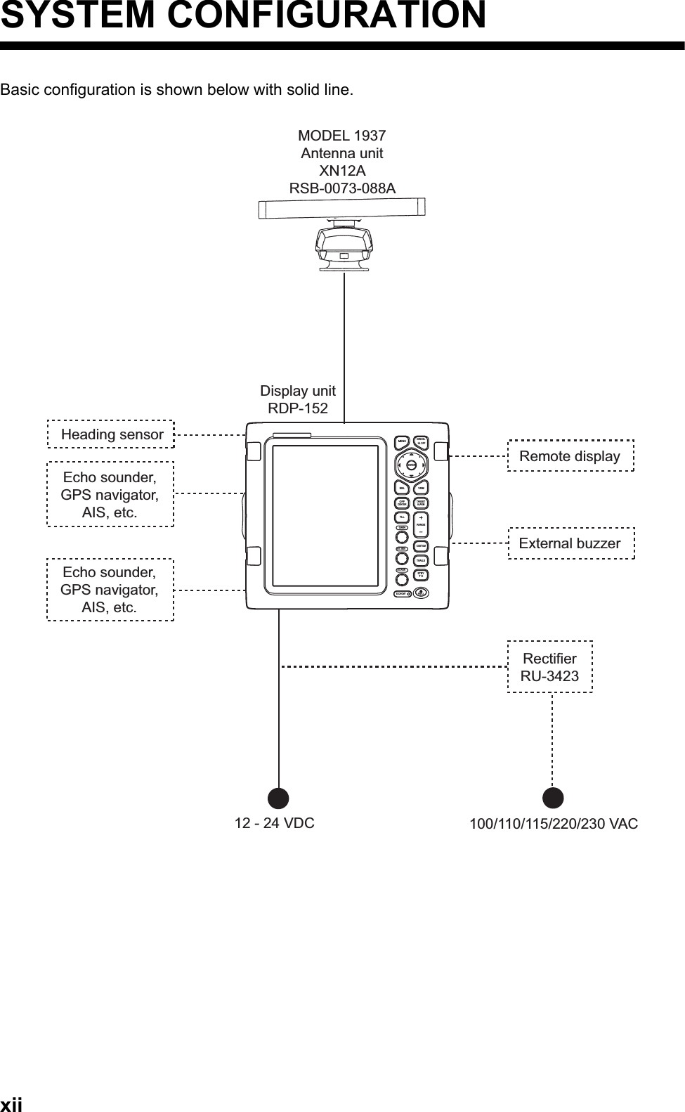
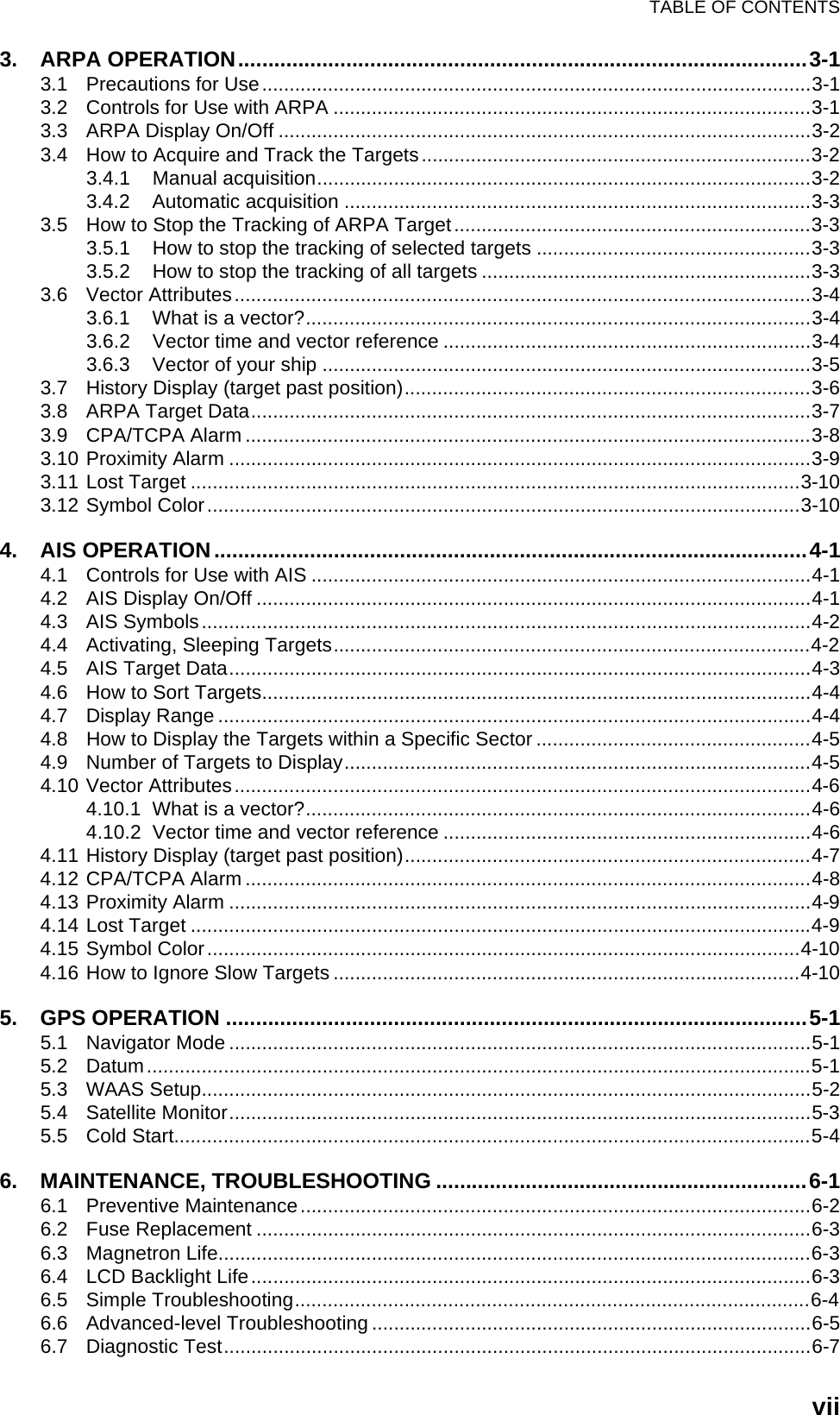
![1. DESCRIPTION OF OPERATION1-31.3 Display IndicationsDisplay indicationsHeadingNav data: Appears at screen bottom when [Data Box]in the [Display] menu is set to [Nav] or [All]. Appropriatesensors required to display nav data.Cursor data(Range and bearing or L/L position)Display modeRange ring intervalRangePulselength Trail referenceNo. 1 EBL bearingNo. 2 EBL bearingOffcenter(M: Manual, A: Auto, C: Custom)North markerTuning indicatorTarget Alarm 1 (2)indicationsNo. 1 VRM rangeNo. 2 VRM rangeWATCHMANTarget alarm zone 1Target alarm zone 2350.0°TRAIL(T)15 S +1.51.5NMNMOFFCENT(A) WTCHeading lineRange ringNo. 2 VRMNo. 2 EBLZoom windowZoom cursorNo. 1 EBLNo. 1 VRMCursorBearing scaleHDG0.5SP CS 1 Custom setting(1 - 3)H UP LAT 34°56.123NLON 135°34.567ESPEED 12.3KNLAT 34°56.123NLON 135°34.567ETTG 01:00BR G 14.8°RNG 0.876NMTTG 00:20OWN SHIP + CURSOR WAYPOINTTUNEAUTOALM1_ACKALM2_OUTSLAVEInput source(shown when display unit functions as remote display)IR 1A/C AUTOVRM0.889NM0.422NMInterference rejectorAuto adjustment ofrain and sea clutters22.0°R270.0°RES 1EAV 1EBLEcho stretchEcho averaging241.0°R 1.592NMVECT TRUE 05:00Vector timeZOOM(R) Zoom indication+Trail time](https://usermanual.wiki/Furuno-USA/9ZWRTR088A.op-man-part-1/User-Guide-1456393-Page-17.png)
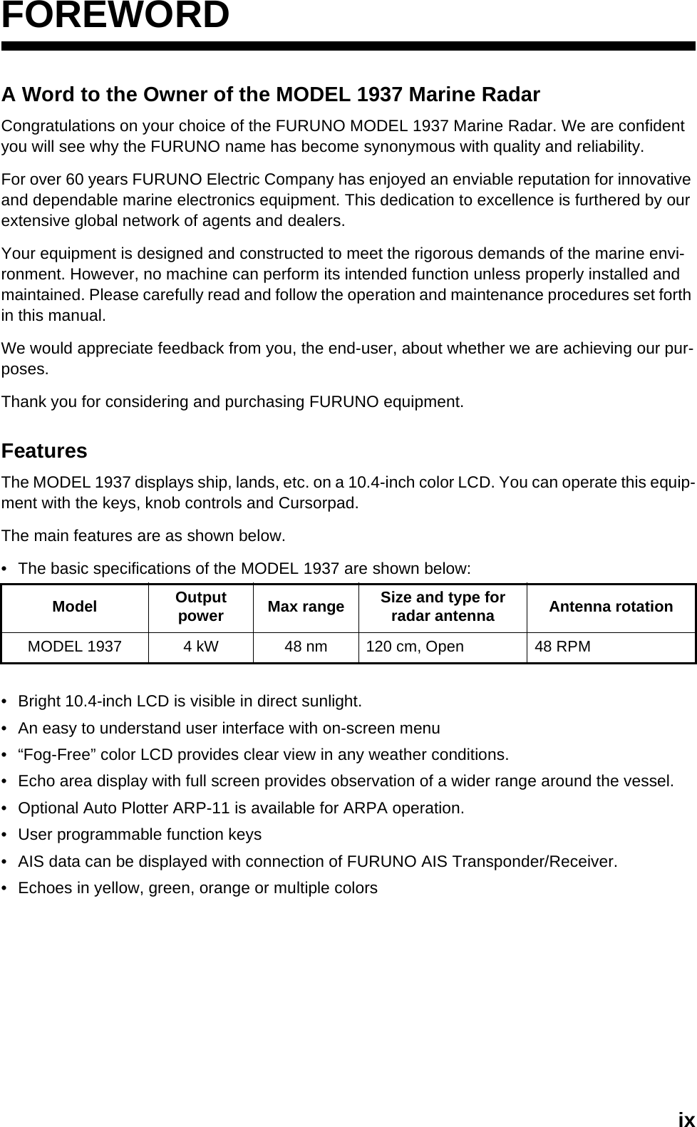
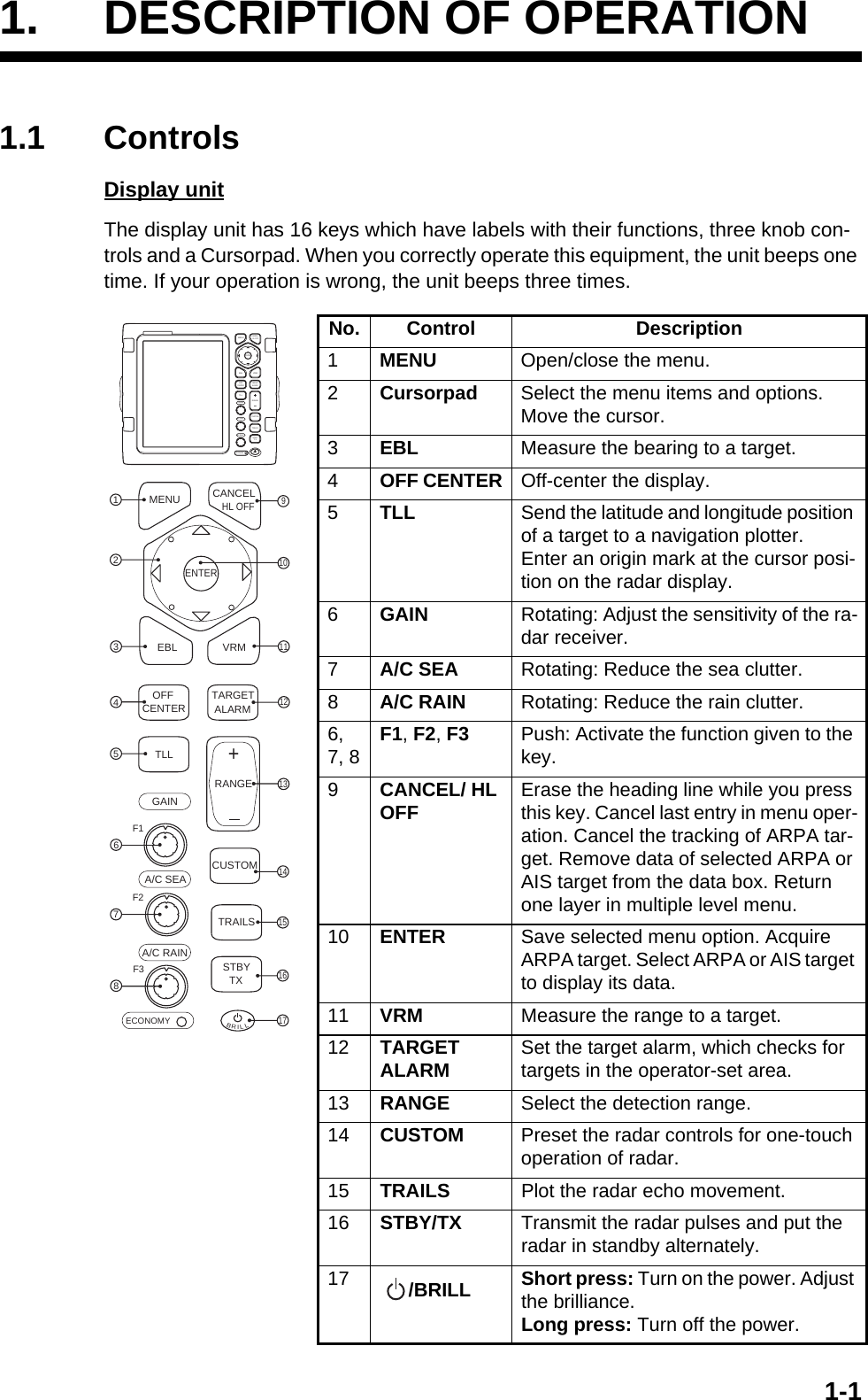
![1. DESCRIPTION OF OPERATION1-41.4 How to Adjust Display Brilliance, Panel DimmerYou can adjust the display brilliance and panel dimmer as follows:1. Press the key momentarily to show the [Brill/Panel] dialog box.Brill/Panel dialog box2. Press the ENTER key (or S, T) to select [Brill] or [Panel].3. Use the Cursorpad (W or X) to adjust. (For brilliance, you can also use the key.)4. Press the CANCEL/HL OFF key to close the window.1.5 Menu DescriptionThis MODEL 1937 has 15 menus and 6 sub menus. Below is the basic procedure for menu operation.1. Press the MENU key to open the menu.MenuBRILL BRILL Cursor*Menu itemsand currentsettingsCurrently selected menuScroll bar (Indicates menus currently not shown in menuwindow. Black vertical line indicates location in menu.You can see the menus and sub menus currently not shownby using or .)MenuTitle bar*Guide message(The simple explanation for the current menu.)*: Title bar in currently controllable column is blue; selected cursor is yellow. Title bar of inactive column is gray.](https://usermanual.wiki/Furuno-USA/9ZWRTR088A.op-man-part-1/User-Guide-1456393-Page-18.png)
![1. DESCRIPTION OF OPERATION1-52. Use the Cursorpad (S or T) to select a menu or a sub menu. The cursor (yellow) in the Menu column indicates the menu currently selected. The menu items in the right window change according to the menu selected.Menu description[Brill/Color]: Adjust the brilliance and color.[DIsplay]: Set up the display-related features.[Echo]: Adjust the echo feature.[Custom 1] - [Custom 3]: Customize the user settings.[Alarm]: Set up the alarm items.[Target Trails]: Process trails of the radar targets.[Tuning]: Adjust the radar tuning.[Others]: Set up other items.[Target]: Set up the targets configuration.[ARPA]: Set up ARPA targets.[AIS]: Set up AIS targets.[GPS]: Set up GP-320B (Black-Box GPS).[System] [Initial]: Initial settings. [Tests]: System diagnostic and LCD test. [Sector Blanks]: Set up the sector blanks to prevent the transmission in a cer-tain area. [Units]: Set up units. [Installation] and [Factory]: For use by the installer. See the Installation Man-ual.3. Press the ENTER key to switch the control to the menu items column. The cursor in the menu column now turns gray and the cursor in the menu items column is yellow. The control moves to the menu items column.To switch the control from the menu items column to the menu column, use the CANCEL/HL OFF key. The color of the title bar of the active column is blue and of the inactive column is gray.4. Use the Cursorpad (S or T) to select a menu item and press the ENTER key. A window with options for the related menu item appears.Example windows5. Use the Cursorpad (S or T) to select an option or numeric value.6. Press the ENTER key to save your selection. To close the window without saving, press the CANCEL/HL OFF key (instead of the ENTER key).7. Press the MENU key to close the menu.Note: The menus on the [IEC] and [Russian-River] types close automatically when there is no menu operation for 10 seconds, according to IEC regulations. The following menus and screens are excluded from this regulation: Alarm message, Alarm status, Tuning Init Adjust, GPS self test, GPS satellite monitor, System self test, System LCD pattern, and Auto installation setup.The menus do not close automatically in the [River] or [Sea] configuration.Display Color options Echo Brill setting window](https://usermanual.wiki/Furuno-USA/9ZWRTR088A.op-man-part-1/User-Guide-1456393-Page-19.png)
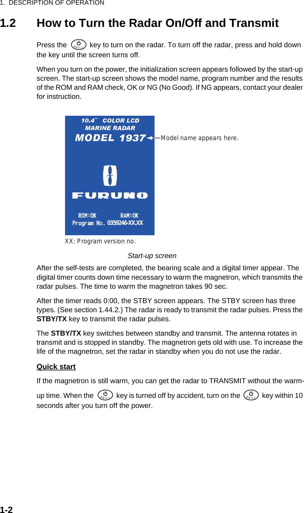
![1. DESCRIPTION OF OPERATION1-61.6 TuningIn default, the radar receiver can be tuned automatically after turning the radar to TX. If you require fine tuning in manual, do the following:1. Transmit the radar and select the maximum range with the RANGE key.2. Press the MENU key to open the menu.3. Use the Cursorpad (S or T) to select [Tuning] and press the ENTER key.Tuning menu4. Use the Cursorpad (S or T) to select [Tuning Mode] and press the ENTER key.Tuning Mode options5. Use the Cursorpad (S or T) to select [Manual] and press the ENTER key.6. Use the Cursorpad (S or T) to select [Manual Tuning] and press the ENTER key. The window shown below appears.Manual Tuning setting window7. Use the Cursorpad (S or T) to adjust the tuning while you look the tuning bar at the upper-right corner of the dis-play. The best tuning point is where the tuning bar moves to maximum value. The vertical bar on the tuning bar shows the tuning voltage.8. Press the ENTER key.9. Press the MENU key to close the menu.Note: If the automatic tuning does not give the correct tuning, run the [Tuning Init Ad-just] again.TUNE MAN Tuning method (Manual)Tuning barVertical bar](https://usermanual.wiki/Furuno-USA/9ZWRTR088A.op-man-part-1/User-Guide-1456393-Page-20.png)
![1. DESCRIPTION OF OPERATION1-71.7 Display ModesThis radar has the display modes shown below. All modes except head-up require a heading signal. The true motion mode additionally requires position data.Relative Motion (RM)• [Head Up] (H UP)• [Course Up] (C UP)• [North Up] (N UP)• [True View] (TRUE VIEW)True Motion (TM)• [True Motion] (TM)1.7.1 How to select the display mode1. Press the MENU key to open the menu.2. Use the Cursorpad (S or T) to select [Display] and press the ENTER key.Display menu3. Use the Cursorpad (S or T) to select [Display Mode] and press the ENTER key.Display Mode options4. Use the Cursorpad (S or T) to select a display mode and press the ENTER key.5. Press the MENU key to close the menu.Note: All modes except head-up require a heading signal in AD-10 format or NMEA format. If the heading signal is lost, the mode is changed to head-up and the north marker disappears. The display for heading is XXX.X and the alarm sounds. The mes-sage "GYRO" (AD-10 format data) or "NMEA_HDG" (NMEA format data) appears in](https://usermanual.wiki/Furuno-USA/9ZWRTR088A.op-man-part-1/User-Guide-1456393-Page-21.png)
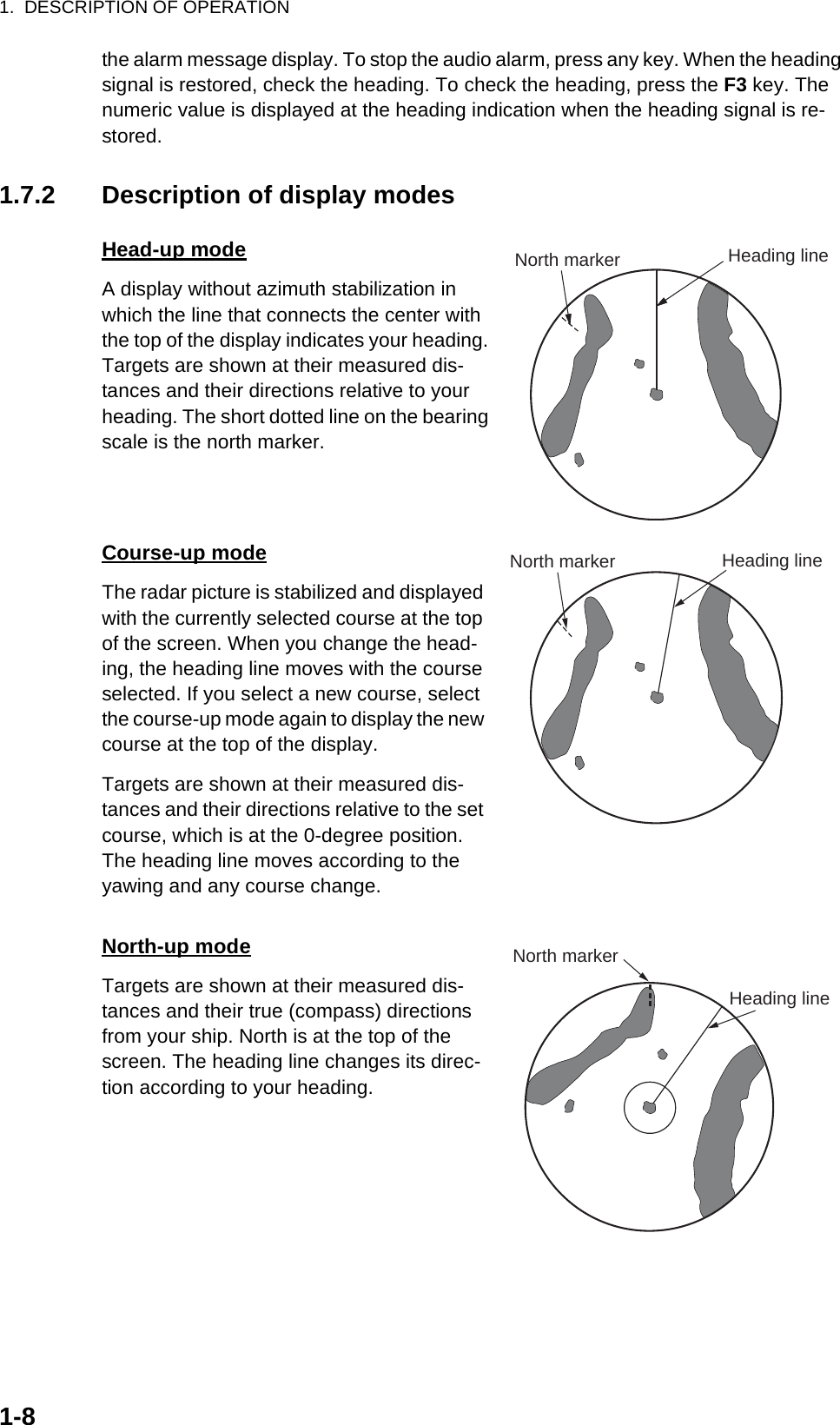
![1. DESCRIPTION OF OPERATION1-9True motion modeYour ship and other objects in motion move with their true courses and speed. All fixed tar-gets, like landmasses, appear as fixed echoes in ground stabilized TM.When your ship reaches a point that is 75% of the radius of the display, the position is reset. The ship appears at 75% radius opposite to the extension of the heading line on the display center. You can manually reset your ship sym-bol if you press the OFF CENTER key.Automatic reset of your ship marker in true motion modeTrue view modeThe echoes move in real time depending on the change of the heading of your ship. Heading line is at the top of the screen. When the heading signal is lost, this function is not available and the display mode automatically changes to the head-up mode. The [Wiper] is not available in this mode (see section 1.31).1.8 How to Select a Range ScaleThe selected range scale, range ring interval and pulselength are shown at the upper- left corner on the screen. When an objective target comes closer, reduce the range scale so that a target appears in 50-90% of the display radius.Use the RANGE key to select range. Press the "+" part of the key to raise the range; the "-" part to lower the range.Heading lineNorth marker000 010 020030040050060070080090100110120130140150160170180190200210220230240250260270280290300310320330 340 350HeadinglineNorthmarker(a) True motion is selected (b) Your ship has reached a point 75% of display radius (c) Your ship is automatically reset to 75% of display radius000 010 020030040050060070080090100110120130140150160170180190200210220230240250260270280290300310320330 340 350 000 010 020030040050060070080090100110120130140150160170180190200210220230240250260270280290300310320330 340 350Heading lineNorth marker Heading lineNorth markerThe echoes movedepending on thechange of the headingof your ship duringone sweep.](https://usermanual.wiki/Furuno-USA/9ZWRTR088A.op-man-part-1/User-Guide-1456393-Page-23.png)
![1. DESCRIPTION OF OPERATION1-101.9 How to Adjust the Gain (sensitivity)The gain functions to adjust the sensitivity of the receiver for the best reception. The gain can be adjusted automatically or manually.1. Press the MENU key to open the menu.2. Use the Cursorpad (S or T) to select [Echo] and press the ENTER key.3. Use the Cursorpad (S or T) to select [Gain Mode] and press the ENTER key.Gain Mode options4. Use the Cursorpad (S or T) to select [Auto] or [Manual] then press the ENTER key. The window for Gain/Sea/Rain indicator shown below appears. This window closes automatically in the [River] or [Sea] mode when there is no menu operation for three seconds. [Auto] is for adjusting the gain automatically. For [Manual], go to Manual mode below.Gain/Sea/Rain indicator5. Press the CANCEL/HL OFF key to close the window.6. Press the MENU key to close the menu.Note: When you want to adjust the gain finely in [Auto] mode, rotate the GAIN knob. The confirmation message appears. If you select [Yes], the mode changes to [Manual] mode. Rotate the GAIN knob to adjust the gain.Confirmation messageManual mode1. Rotate the GAIN knob to adjust the gain so that weak noise appears on all of the screen. If the gain is too low, weak echoes are erased. If the gain is too high, the background noise hides weak targets.2. Press the CANCEL/HL OFF key to close the window.AUTO: Auto, MAN: ManualGain setting barAre you sure to change to manual mode?](https://usermanual.wiki/Furuno-USA/9ZWRTR088A.op-man-part-1/User-Guide-1456393-Page-24.png)
![1. DESCRIPTION OF OPERATION1-111.10 How to Reduce the Sea ClutterThe reflected echoes from the waves appear around your ship and have the name "sea clutter". The sea clutter extends according to the height of waves and antenna above the water. When the sea clutter hides the targets, use the A/C SEA control to reduce the clutter, either manually or automatically.1. Press the MENU key to open the menu.2. Use the Cursorpad (S or T) to select [Echo] and press the ENTER key.3. Use the Cursorpad (S or T) to select [Sea Mode] and press the ENTER key.4. Use the Cursorpad (S or T) to select [Auto] or [Manual] then press the ENTER key. The window for Gain/Sea/Rain indicator appears (refer to the illustration at step 4 in section 1.9). If you selected [Auto], go to step 5. For [Manual], go to Man-ual mode below.5. Press the CANCEL/HL OFF key to close the window. [Auto] is for reducing the sea clutter automatically. If the sea clutter is strong while cruising along a coast-line in the [Auto] mode, go to step 6. If not, go to step 9.6. Use the Cursorpad (S or T) to select [Auto Sea] and press the ENTER key.Auto Sea options7. Use the Cursorpad (S or T) to select [Coastal] or [Advanced] then press the EN-TER key. The window for Gain/Sea/Rain indicator appears for confirmation.[Coastal]: Suppress both land and sea clutter. For cruising along a coastline.[Advanced]: Automatically discriminate land echoes from sea reflections to sup-press only sea reflections. Use this mode for general use.8. Press the CANCEL/HL OFF key to close the window.9. Press the MENU key to close the menu.Note: When you want to adjust the sea clutter finely in [Auto] mode, rotate the A/C SEA knob. The confirmation message appears. If you select [Yes], the mode changes to [Manual] mode. Rotate the A/C SEA knob to adjust the sea clutter.Confirmation messageManual mode1. Rotate the A/C SEA knob to reduce the sea clutter.Note: When the setting of the A/C SEA control is correct, the clutter is broken into small dots, and small targets become identified. If the setting is not enough, tar-gets are hidden in the clutter. If the setting is higher than necessary, both sea clut-ter and targets disappear from the display. Normally adjust the control until the clutter has disappeared to leeward, but a small amount of the clutter is visible windward.Are you sure to change to manual mode?](https://usermanual.wiki/Furuno-USA/9ZWRTR088A.op-man-part-1/User-Guide-1456393-Page-25.png)
![1. DESCRIPTION OF OPERATION1-12Sea clutter2. Press the CANCEL/HL OFF key to close the window.1.11 How to Reduce the Rain ClutterThe reflections from the rain or snow appear on the screen. These reflections have the name "rain clutter". When the rain clutter is strong, targets in the rain clutter are hidden in the clutter. Reflections from the rain clutter are easily identified from true targets by their wool-like appearance.The A/C RAIN control, like the A/C SEA control, adjusts the receiver sensitivity, but in longer range. If the setting is high, the rain clutter is more reduced. The rain control breaks the continuous display of rain or snow reflections into a random pattern. When the rain clutter hides the targets, adjust the rain control (automatic or manual) to re-duce the clutter.1. Press the MENU key to open the menu.2. Use the Cursorpad (S or T) to select [Echo] and press the ENTER key.3. Use the Cursorpad (S or T) to select [Rain Mode] and press the ENTER key.4. Use the Cursorpad (S or T) to select [Auto] or [Manual] then press the ENTER key. The window for Gain/Sea/Rain indicator appears (refer to the illustration of step 4 at section 1.9). If you selected [Auto], go to step 5. For [Manual], go to Man-ual mode below.5. Press the CANCEL/HL OFF key to close the window.6. Use the Cursorpad (S or T) to select [Auto Rain] and press the ENTER key.Auto Rain options7. Use the Cursorpad (S or T) to select [Calm], [Moderate] or [Rough] then press the ENTER key. The window for Gain/Sea/Rain indicator appears for confirma-tion.[Calm]: For light rain[Moderate]: When you can not reduce the rain clutter with [Calm] mode[Rough]: For heavy rain8. Press the CANCEL/HL OFF key to close the window.9. Press the MENU key to close the menu.A/C SEA control adjusted;sea clutter reducedSea clutter atscreen center](https://usermanual.wiki/Furuno-USA/9ZWRTR088A.op-man-part-1/User-Guide-1456393-Page-26.png)
![1. DESCRIPTION OF OPERATION1-13Note: When you want to adjust the rain clutter finely in [Auto] mode, rotate the A/C RAIN knob. The confirmation message appears. If you select [Yes], the mode chang-es to [Manual] mode. Rotate the A/C RAIN knob to adjust the rain clutter.Confirmation messageManual mode1. Rotate the A/C RAIN knob to reduce the rain clutter.2. Press the CANCEL/HL OFF key to close the window.Rain clutter1.12 Automatic Adjustments of Sea and Rain Clutters When you can not correctly reduce the sea clutter or rain clutter with related control, turn on the automatic anti-clutter feature. When this feature is turned on, "A/C AUTO" appears at the lower-right corner.1. Press the MENU key to open the menu.2. Use the Cursorpad (S or T) to select [Echo] and press the ENTER key.3. Use the Cursorpad (S or T) to select [A/C Auto] and press the ENTER key.4. Use the Cursorpad (S or T) to select [Off] or [On] then press the ENTER key.5. Press the MENU key to close the menu.Caution on use• [A/C Auto] can lower an echo which covers a wide area, like land or an island.• When [A/C Auto] is active, the strength of a target in sea clutter or rain clutter can be lower than actual strength. In this case change to manual A/C Sea and manual A/C Rain and adjust the picture.Are you sure to change to manual mode?Rain clutter atscreen center A/C RAIN control adjusted;rain clutter reducedA/C Auto: Off A/C Auto: On:£:¸:Å:»Land:£:¸:Å:»Target](https://usermanual.wiki/Furuno-USA/9ZWRTR088A.op-man-part-1/User-Guide-1456393-Page-27.png)
![1. DESCRIPTION OF OPERATION1-141.13 CursorThe cursor functions to find the range and bearing (default function) to a target or the latitude and longitude position of a target. Use the Cursorpad to position the cursor and read the cursor data at the screen bottom.Cursor dataCursor dataYou can show the cursor data as range and bearing (from your ship to the cursor) or latitude and longitude. Position and heading signal are required.1. Press the MENU key to open the menu.2. Use the Cursorpad (S or T) to select [Others] and press the ENTER key.Others menuCursor data(range and bearing, or latitutde and longitude)110.1° R 0.488 NM NM0.5Cursor++](https://usermanual.wiki/Furuno-USA/9ZWRTR088A.op-man-part-1/User-Guide-1456393-Page-28.png)
![1. DESCRIPTION OF OPERATION1-153. Use the Cursorpad (S or T) to select [Cursor Position] and press the ENTER key.Cursor Position options4. Use the Cursorpad (S or T) to select [Rng/Brg] or [Lat/Lon] then press the EN-TER key. (When the navigation data is displayed, cursor latitude and longitude po-sition cannot be displayed.)5. Press the MENU key to close the menu.1.14 Interference RejectorThe radar interference can occur when your ship is near the radar of another ship that operates on the same frequency band with your radar. The interference shows on the screen as many bright dots. The dots can be random or in the shape of dotted lines that run from the center to the edge of the display. You can identify the interference from the normal echoes, because the interference does not appear in the same loca-tion at the next antenna rotation. When this feature is turned on, "IR 1", "IR 2" or "IR 3" appears at the lower-right corner.Interference1. Press the MENU key to open the menu.2. Use the Cursorpad (S or T) to select [Echo] and press the ENTER key.3. Use the Cursorpad (S or T) to select [Int Rejector] and press the ENTER key.Int Rejector options4. Use the Cursorpad (S or T) to select [Off], [1], [2] or [3] then press the ENTER key. [3] removes the interference the most.5. Press the MENU key to close the menu.Note: When there is no interference, turn off the interference rejector so you do not miss the small targets.Indication at the lower-right cornerIR 1IR 2IR 3](https://usermanual.wiki/Furuno-USA/9ZWRTR088A.op-man-part-1/User-Guide-1456393-Page-29.png)
![1. DESCRIPTION OF OPERATION1-161.15 How to Measure the Range to a TargetYou can measure the range to a target in three methods. You can use the fixed range rings, the cursor (if set to measure range and bearing), and the VRM (Variable Range Marker).Use the fixed range rings to get a rough estimate of the range to a target. The fixed range rings are the concentric solid circles about your ship. The number of rings changes with the selected range scale. The interval of the range ring is displayed at the upper-left corner of the screen. Count the number of rings between the center of the display and the target. Check the range ring interval and measure the distance of the echo from the nearest ring.1.15.1 How to adjust range ring brilliance1. Press the MENU key to open the menu.2. Use the Cursorpad (S or T) to select [Brill/Color] and press the ENTER key.Brill/Color menu3. Use the Cursorpad (S or T) to select [Rings Brill] and press the ENTER key.Rings Brill options4. Use the Cursorpad (S or T) to select an option and press the ENTER key. [4] is the brightest. [Off] turns off the range rings.5. Press the MENU key to close the menu.](https://usermanual.wiki/Furuno-USA/9ZWRTR088A.op-man-part-1/User-Guide-1456393-Page-30.png)
![1. DESCRIPTION OF OPERATION1-171.15.2 How to measure the range with a VRMThere are two VRMs, No. 1 and No. 2. The VRMs are dashed rings so that you can identify the rings from the fixed range rings. You can identify VRM 1 from VRM 2 by different lengths of dashes. The dashes of the No. 1 VRM are shorter than those of the No. 2 VRM.1. Press the VRM key to display either of the VRMs. Press the VRM key to change the active VRM between No. 1 and No. 2. The indication of the currently active VRM is in a rectangle.2. Use the Cursorpad to align the Variable Range Marker with the inner edge of the target. Read the distance at the lower-right corner of the screen. Each VRM re-mains at the same geographical distance when you operate the RANGE key. The size of the VRM ring changes in proportion to the selected range scale.3. Press the ENTER key to anchor the VRM.4. To erase a VRM, press the VRM key to activate the VRM and press the CANCEL/HL OFF key.How to measure the range with the VRM1.15.3 How to select VRM unitYou can select the unit of measurement used by the VRM. The selections are nautical miles (NM), kilometers (KM), statute miles (SM) or kiloyard (KYD). The cursor range unit is also changed when the VRM unit is changed.1. Press the MENU key to open the menu.2. Use the Cursorpad (S or T) to select [Others] and press the ENTER key.VRM 1Cursor range and bearingVRM 2Target+VRM5.044NM2.082NMCursor (+)VRM 1 rangeVRM 2 range+ The currently active VRMis in a rectangle.37.4° R 5.044 NM VECT TRUE 05:00](https://usermanual.wiki/Furuno-USA/9ZWRTR088A.op-man-part-1/User-Guide-1456393-Page-31.png)
![1. DESCRIPTION OF OPERATION1-183. Use the Cursorpad (S or T) to select [VRM Unit] and press the ENTER key.VRM Unit options4. Use the Cursorpad (S or T) to select the unit and press the ENTER key.5. Press the MENU key to close the menu.1.16 How to Measure the Bearing to a TargetUse the Electronic Bearing Line (EBL) to take a bearing of a target. There are two EBLs, No. 1 and No. 2. Each EBL is a straight dashed line from the center of the screen to the edge. The dashes of the No. 1 EBL are shorter than those of the No. 2 EBL.1.16.1 How to measure the bearing with an EBL1. Press the EBL key to display either of the EBLs. Press the EBL key to change the active EBL between No. 1 and No. 2. The indication of the currently active EBL is in a rectangle.2. Use the Cursorpad to put the EBL on the center of the target. Read the bearing at the lower-left corner of the screen.3. Press the ENTER key to anchor the EBL.4. To erase an EBL, press the EBL key to activate the EBL and press the CANCEL/HL OFF key.How to measure the bearing with the EBLNM: 0.1 NM or aboveYD: Less than 0.1 NM+EBL270.0° R 45.0° R45.0° R 5.044 NM + EBL 1 EBL 2Cursor range and bearingTargetCursor (+)The currently active EBLis in a rectangle.EBL 1 bearingEBL 2 bearingVECT TRUE 05:00](https://usermanual.wiki/Furuno-USA/9ZWRTR088A.op-man-part-1/User-Guide-1456393-Page-32.png)
![1. DESCRIPTION OF OPERATION1-191.16.2 EBL reference"R" (relative) follows the EBL indication if the bearing is relative to the heading of your ship. "T" (true) follows the EBL indication if the bearing is in reference to the north. You can select relative or true in the head-up and true view modes. The bearing indication is true in all other modes. True bearing requires a heading sensor.1. Press the MENU key to open the menu.2. Use the Cursorpad (S or T) to select [Others] and press the ENTER key.3. Use the Cursorpad (S or T) to select [EBL Reference] and press the ENTER key.EBL Reference options4. Use the Cursorpad (S or T) to select [Relative] or [True] then press the ENTER key.5. Press the MENU key to close the menu.1.17 How to Measure the Range and Bearing Between Two TargetsYou can move the origin of the EBL to measure the range and bearing between two targets.1. Press the EBL key to select the bearing indication of EBL 1 or EBL 2. The indica-tion of the currently active EBL is in a rectangle.2. Use the Cursorpad to put the cursor on the center of the target A.3. Press the OFF CENTER key to move the origin of the EBL to the location selected at step 2.4. Use the Cursorpad to put the cursor on the center of the target B.5. Press the VRM key to display the VRM having the same number as the EBL acti-vated at step 1. The indication of the currently active VRM is in a rectangle.6. Use the Cursorpad to set the VRM on the inner edge of the target B.](https://usermanual.wiki/Furuno-USA/9ZWRTR088A.op-man-part-1/User-Guide-1456393-Page-33.png)
![1. DESCRIPTION OF OPERATION1-207. Read the bearing and range indications at the bottom of the screen.How to measure the range and bearing between two targetsWhen you press the OFF CENTER key in EBL operation, the origin of an EBL moves between the screen center and cursor location. To return the origin of an EBL to the screen center, press the ENTER key when the origin of an EBL is on the screen cen-ter.1.18 How to Select a PulselengthThe pulselength in use appears at the upper-left position on the screen. The pulse-lengths are set to each range scale and custom setup. You can change the pulse-length on the 1.5 nm, 1.6 nm, 3 nm or 3.2 nm range with the following procedure. Pulselength cannot be changed on other ranges. (You can change the pulselength on the 2 nm or 4 nm range in the [Russian-River] mode.) Use a longer pulse when your purpose is long range detection. Use a shorter pulse when the resolution is important.Note: Press the CUSTOM key several times to activate the [Echo] menu until the CS 1 (2, 3) indication (custom setting) disappears from the screen. See the illustration in section 1.3.1. Press the MENU key to open the menu.EBL origin++Target BRange/bearing betweentargets A and B Range/bearing betweentargets C and DEBL 2VRM 2EBL 1VRM 1EBL 45.0° R327.0° RVRM0.550NM0.550NMTarget A Target DTarget C](https://usermanual.wiki/Furuno-USA/9ZWRTR088A.op-man-part-1/User-Guide-1456393-Page-34.png)
![1. DESCRIPTION OF OPERATION1-212. Use the Cursorpad (S or T) to select [Echo] and press the ENTER key.Echo menu3. Use the Cursorpad (S or T) to select [Pulse Length] and press the ENTER key.Pulse Length options4. Use the Cursorpad (S or T) to select [Short] or [Long] then press the ENTER key.The pulselength indication at the upper-left corner changes according to your se-lection as shown below.1.5 nm or 1.6 nm (or 2 nm in the [Russian-River] mode): "SP" for [Short] pulse, "MP" for [Long] pulse3 nm or 3.2 nm (or 4 nm in the [Russian-River] mode): "MP" for [Short] pulse, "LP" for [Long] pulse5. Press the MENU key to close the menu.1.19 Target AlarmThe target alarm looks for targets (ship, landmass, etc.) in the area you set. Audiovisual alarms are released when a target enters (or exits) the alarm area.CAUTIONCAUTION· Do not depend on the alarm as the only means to detect possible collision situations.· Adjust the A/C SEA, A/C RAIN and GAIN controls correctly so that the alarm system does not miss the target echoes.](https://usermanual.wiki/Furuno-USA/9ZWRTR088A.op-man-part-1/User-Guide-1456393-Page-35.png)
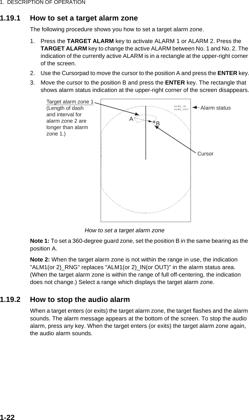
![1. DESCRIPTION OF OPERATION1-231.19.3 How to select the alarm typeYou can set the target alarm to activate against targets entering or exiting the alarm zone.In and Out target alarms1. Press the MENU key to open the menu.2. Use the Cursorpad (S or T) to select [Alarm] and press the ENTER key.Alarm menu3. Use the Cursorpad (S or T) to select [Target Alarm 1] or [Target Alarm 2] then press the ENTER key.Target Alarm options4. Use the Cursorpad (S or T) to select [In] or [Out].[In]: When the targets enter a target alarm zone, the alarm sounds.[Out]: When the targets exit a target alarm zone, the alarm sounds.5. Press the ENTER key followed by the MENU key.1.19.4 How to sleep a target alarm temporarilyWhen you do not require a target alarm temporarily, you can sleep the target alarm. The alarm zone remains on the screen, but any targets that enter (or exit) the alarm zone do not trigger the audio and visual alarms.1. Press the TARGET ALARM key to select the ALARM 1 or ALARM 2 indication at the upper-right corner on the screen. The selected indication is in a rectangle.“In” target alarm “Out” target alarm](https://usermanual.wiki/Furuno-USA/9ZWRTR088A.op-man-part-1/User-Guide-1456393-Page-37.png)
![1. DESCRIPTION OF OPERATION1-242. Press the CANCEL/HL OFF key. The alarm indication now shows "ALM1(or 2)_ACK".To activate a sleeping target alarm zone, press the TARGET ALARM key to select the ALARM 1 or ALARM 2 and press the ENTER key. The alarm indication then changes to "ALM1(or 2)_IN(or OUT)".1.19.5 How to deactivate a target alarm1. Press the TARGET ALARM key to select the ALARM 1 or ALARM 2 indication at the upper-right corner on the screen. The selected indication is in a rectangle.2. Press the CANCEL/HL OFF key. The alarm indication now shows "ALM1(or 2)_ACK".3. Press the TARGET ALARM key. The alarm indication "ALM1(or 2)_ACK" is shown in a dashed-line rectangle.4. Press the CANCEL/HL OFF key. The target alarm zone and the alarm indication are erased from the screen.1.19.6 How to select the target strength which triggers a target alarmYou can select the target strength which triggers the target alarm as follows:1. Press the MENU key to open the menu.2. Use the Cursorpad (S or T) to select [Alarm] and press the ENTER key.3. Use the Cursorpad (S or T) to select [Alarm Level] and press the ENTER key.Alarm Level options4. Use the Cursorpad (S or T) to select the echo strength level.5. Press the ENTER key followed by the MENU key.1.19.7 How to turn the buzzer on/offYou can turn on/off the panel buzzer or external buzzer for target alarms. The panel buzzer is for this equipment. The external buzzer is for the optional buzzer, which is connected to this equipment to give the target alarm at a remote location.1. Press the MENU key to open the menu.2. Use the Cursorpad (S or T) to select [Alarm] and press the ENTER key.3. Use the Cursorpad (S or T) to select [Panel Buzzer] (or [External Buzzer] for op-tional buzzer) and press the ENTER key.Panel Buzzer and External Buzzer options4. Use the Cursorpad (S or T) to select [On] or [Off] then press the ENTER key.5. Press the MENU key to close the menu.](https://usermanual.wiki/Furuno-USA/9ZWRTR088A.op-man-part-1/User-Guide-1456393-Page-38.png)
![1. DESCRIPTION OF OPERATION1-251.20 How to Off-center the DisplayYou can off-center your ship position to expand the view field without selecting a larger range scale. The display can be off-centered manually, or automatically according to speed of the ship.Note: Off-centering is not available in the true motion mode.1.20.1 How to select the off-center mode1. Press the MENU key to open the menu.2. Use the Cursorpad (S or T) to select [Display] and press the ENTER key.3. Use the Cursorpad (S or T) to select [Offcenter Mode] and press the ENTER key.Offcenter Mode options4. Use the Cursorpad (S or T) to select [Manual], [Custom] or [Auto] then press the ENTER key. Press the ENTER key to change between on and off.5. After setting all options, use the Cursorpad (T) to select [EXIT? YES] and press the ENTER key.6. Press the MENU key to close the menu.1.20.2 Off-center the displayPress the OFF CENTER key to move your ship position. When you press the OFF CENTER key continuously, the mode changes in the sequence of OFF → Manual → Custom → Auto → OFF → Manual → ... (the options available depend on setting se-lected at step 4 in section 1.20.1). When off-centering is active, "OFFCENT(M)", "OFFCENT(C)" or "OFFCENT(A)" appears at the upper-left corner on the display.Manual (Indication: "OFFCENT(M)")You can move your ship position to the current cursor position on all modes except true motion, within 75% of the available display area.1. Press the OFF CENTER key several times until the off-center indication disap-pears.2. Put the cursor on the position where to off-center the display.3. Press the OFF CENTER key several times until the indication "OFFCENT(M)" ap-pears.Press the ENTER keyto change betweenon and off.](https://usermanual.wiki/Furuno-USA/9ZWRTR088A.op-man-part-1/User-Guide-1456393-Page-39.png)
![1. DESCRIPTION OF OPERATION1-26Custom (Indication: "OFFCENT(C)")You can move your ship position to the position which you pre-set. Follow the proce-dure shown below to register the cursor position.1. Press the OFF CENTER key several times until the off-center indication disap-pears.2. Put the cursor on the position where to off-center the display.3. Press the OFF CENTER key several times until the indication "OFFCENT(M)" ap-pears.4. Press the MENU key to open the menu.5. Use the Cursorpad (S or T) to select [Display] and press the ENTER key.6. Use the Cursorpad (S or T) to select [Save Offcenter] and press the ENTER key. The message "Complete" appears.7. Press any key to close the message window.8. Press the MENU key to close the menu.To change the mode to custom, press the OFF CENTER key several times until the indication "OFFCENT(C)" appears.Auto (Indication: "OFFCENT(A)")The amount of automatic move is calculated according to speed of the ship. The max-imum amount is 75% of the range in use. The formula to calculate automatic shift is shown below.If the offcenter speed setting is 15 knots and the speed of the ship is 10 knots, for ex-ample, the amount of move at the stern of your ship will be 50% of the available display area.How to select offcenter speed1. Press the MENU key to open the menu.2. Use the Cursorpad (S or T) to select [Initial] sub menu in [System] menu and press the ENTER key.3. Use the Cursorpad (S or T) to select [Offcenter Speed] and press the ENTER key.Offcenter Speed setting window4. Use the Cursorpad (S or T) to select the speed to use and press the ENTER key.5. Press the MENU key to close the menu.Offcenter speed setting X 0.75 = Amount of move (%)Speed of ship](https://usermanual.wiki/Furuno-USA/9ZWRTR088A.op-man-part-1/User-Guide-1456393-Page-40.png)
![1. DESCRIPTION OF OPERATION1-271.21 ZoomThe zoom function expands the length and width of a selected target as much as twice its normal size, in the zoom window. You select the target to zoom with the zoom cur-sor. The selected target is zoomed in the zoom window.ARPA and AIS symbols can be displayed in the zoom window, but are not zoomed. You can process ARPA and AIS targets that are in the zoom window, in the same method as on the normal radar display.There are three types of zoom.[Relative]: The zoom cursor is fixed to the range and bearing from your ship.[True]: The zoom cursor is fixed to set geographical position.[Target]: The zoom cursor is fixed to the zoomed AIS or ARPA target.1.21.1 Zoom modeYou can select the zoom mode from [Relative], [True] or [Target].1. Press the MENU key to open the menu.2. Use the Cursorpad (S or T) to select [Display] and press the ENTER key.3. Use the Cursorpad (S or T) to select [Zoom Mode] and press the ENTER key.Zoom Mode options4. Use the Cursorpad (S or T) to select [Relative], [True] or [Target] then press the ENTER key.Note: True zoom mode requires a heading signal and position data.5. Press the MENU key to close the menu.1.21.2 How to zoomRelative or True zoom mode1. Use the Cursorpad to put the cursor on the position desired.2. Press the MENU key to open the menu.3. Use the Cursorpad (S or T) to select [Display] and press the ENTER key.4. Use the Cursorpad (S or T) to select [Zoom] and press the ENTER key.Zoom options5. Use the Cursorpad (S or T) to select [On] and press the ENTER key.The ZOOM indication appears at the upper-left corner on the screen. The zoom window and the zoom cursor also appear (see the illustration on the next page). To quit the zoom, select [Off] instead of [On] and press the ENTER key.6. Press the MENU key to close the menu.](https://usermanual.wiki/Furuno-USA/9ZWRTR088A.op-man-part-1/User-Guide-1456393-Page-41.png)
![1. DESCRIPTION OF OPERATION1-28Target zoom modeThe ARPA or AIS target as below can be displayed in the zoom window:ARPA: The symbol is enlarged twice its normal size.AIS: The symbol is enclosed in a broken square. (The symbol is not enlarged.)The zoom cursor moves with the ARPA or AIS target.Note: If neither ARPA nor AIS targets are selected, the message "NO TARGET." ap-pears. Press any key to erase the message.1. Press the MENU key to open the menu.2. Use the Cursorpad (S or T) to select [Display] and press the ENTER key.3. Use the Cursorpad (S or T) to select [Zoom] and press the ENTER key.4. Use the Cursorpad (S or T) to select [On] and press the ENTER key.The ZOOM indication appears at the upper-left corner on the screen. The zoom window and the zoom cursor also appear (see the following illustration). To quit the zoom, select [Off] instead of [On] and press the ENTER key.5. Press the MENU key to close the menu.1.51.5NMNMZoom window255.5°R 1.094NMZOOM(T)+Zoom cursorZoom indicationVECT TRUE 05:00+1.51.5NMNM255.5°R 1.094NMZOOM(T)+VECT TRUE 05:00+Relative or True zoom mode(example: true zoom) Target zoom mode(example: AIS)999999000999999000](https://usermanual.wiki/Furuno-USA/9ZWRTR088A.op-man-part-1/User-Guide-1456393-Page-42.png)
![1. DESCRIPTION OF OPERATION1-291.22 Echo StretchThe echo stretch feature enlarges the targets in the range and bearing directions to make the targets easier to see. This feature is available on any range. There are three levels of echo stretch, [1], [2] and [3]. [3] enlarges the targets the most.Note: The echo stretch magnifies the targets, sea and rain clutters, and radar interfer-ence. Correctly adjust the sea clutter, rain clutter and radar interference before you ac-tivate the echo stretch.1. Press the MENU key to open the menu.2. Use the Cursorpad (S or T) to select [Echo] and press the ENTER key.3. Use the Cursorpad (S or T) to select [Echo Stretch] and press the ENTER key.Echo Stretch options4. Use the Cursorpad (S or T) to select an echo stretch option and press the EN-TER key.5. Press the MENU key to close the menu. When the echo stretch is active, "ES 1 (2, or 3)" appears at the lower-left corner on the display.1.23 Echo AverageTo identify true target echoes from the sea clutter, echoes are averaged over succes-sive picture frames. If an echo is solid and stable, the echo is shown in its normal in-tensity. The brilliance of sea clutter is reduced to easily identify true targets from the sea clutter.Note 1: Do not use the echo average function under heavy pitching and rolling. You can lose a target.Note 2: This feature requires a heading signal and position data. When either signal becomes lost, echo average is deactivated.To correctly use the echo average function, first reduce the sea clutter with the A/C SEA control, then do as follows:1. Press the MENU key to open the menu.2. Use the Cursorpad (S or T) to select [Echo] and press the ENTER key.3. Use the Cursorpad (S or T) to select [Echo Average] and press the ENTER key.Echo Average options](https://usermanual.wiki/Furuno-USA/9ZWRTR088A.op-man-part-1/User-Guide-1456393-Page-43.png)
![1. DESCRIPTION OF OPERATION1-304. Use the Cursorpad (S or T) to select an echo averaging option and press the EN-TER key.[Off]: Deactivate the echo average.[1]: Identify true targets from the sea clutter and reduce the brilliance of unstable echoes.[2]: Identify true targets from the sea clutter that you cannot reduce the brilliance with setting 1.[Auto]: Identify true targets from the sea clutter. Detect far and unstable targets.5. Press the MENU key to close the menu. The selected echo average ("EAV 1", "EAV 2" or "EAV(A)") appears at the lower-left corner of the display.1.24 Target TrailsThe trails of the radar targets can be shown simulated in afterglow to check target movement. The target trails are selected for either relative or true. True motion trails require a heading signal and position data.1.24.1 Trail time1. Press the MENU key to open the menu.2. Use the Cursorpad (S or T) to select [Target Trails] and press the ENTER key.3. Use the Cursorpad (S or T) to select [Time] and press the ENTER key.Time options4. Use the Cursorpad (S or T) to select time and press the ENTER key. Press the ENTER key to change between on and off.5. After setting all options, use the Cursorpad (T) to select [EXIT? YES] and press the ENTER key.6. Press the MENU key to close the menu.Press the ENTER keyto change betweenon and off.](https://usermanual.wiki/Furuno-USA/9ZWRTR088A.op-man-part-1/User-Guide-1456393-Page-44.png)
![1. DESCRIPTION OF OPERATION1-311.24.2 How to start, stop the trails1. Press the TRAILS key to start the trails and select the trail time. The selected time with the trail mode is shown at the upper-right corner as in the figure shown below. The available trail time with the TRAILS key changes according to trail times, which you turn on in section 1.24.1.Trail indications2. To change the trail time, press the TRAILS key until the desired trail time is dis-played. The trail lengthens with the trail time.Note 1: To erase the trails, press and hold the TRAILS key until a beep sounds, or select [All Cancel] on the [Target Trails].Note 2: To deactivate the trails, press the TRAILS key several times until the trail in-dications disappear from the display.1.24.3 Trail modeYou can display the echo trails in true or relative motion.True modeThe true trails show true target movements according to their over-the-ground speeds and courses. The stationary targets do not show the trails. The true trails require a heading signal and position data.Relative modeThe relative trails show other ships’ movements relative to your ship. The stationary targets also show the trails.True trails and relative trailsTo select the trail mode, do the following:1. Press the MENU key to open the menu.2. Use the Cursorpad (S or T) to select [Target Trails] and press the ENTER key.TRAIL(T)15 STrail Mode (T: True, R: Relative)Trail TimeTrue target trails Relative target trails](https://usermanual.wiki/Furuno-USA/9ZWRTR088A.op-man-part-1/User-Guide-1456393-Page-45.png)
![1. DESCRIPTION OF OPERATION1-323. Use the Cursorpad (S or T) to select [Mode] and press the ENTER key.Mode options4. Use the Cursorpad (S or T) to select [Relative] or [True] then press the ENTER key.5. Press the MENU key to close the menu.1.24.4 Trail gradationTrails can be shown in single or multiple gradation. Multiple gradation fades the gra-dation over time.1. Press the MENU key to open the menu.2. Use the Cursorpad (S or T) to select [Target Trails] and press the ENTER key.3. Use the Cursorpad (S or T) to select [Gradation] and press the ENTER key.Gradation options4. Use the Cursorpad (S or T) to select [Single] or [Multi] then press the ENTER key.Trail gradation5. Press the MENU key to close the menu.1.24.5 Trail colorYou can select the color for trails as follows:1. Press the MENU key to open the menu.2. Use the Cursorpad (S or T) to select [Target Trails] and press the ENTER key.3. Use the Cursorpad (S or T) to select [Color] and press the ENTER key.Color options4. Use the Cursorpad (S or T) to select a color and press the ENTER key.5. Press the MENU key to close the menu. Multiple(Gradual shading)Single(Monotone shading)](https://usermanual.wiki/Furuno-USA/9ZWRTR088A.op-man-part-1/User-Guide-1456393-Page-46.png)
![1. DESCRIPTION OF OPERATION1-331.24.6 Trail levelYou can select which target strength to display.1. Press the MENU key to open the menu.2. Use the Cursorpad (S or T) to select [Target Trails] and press the ENTER key.3. Use the Cursorpad (S or T) to select [Level] and press the ENTER key.Level options4. Use the Cursorpad (S or T) to select [1], [2] or [3] then press the ENTER key.[1]: Display the trails for all targets (including weak targets).[2]: Display the trails for medium-to-strong level targets.[3]: Display the trails for only strong targets.5. Press the MENU key to close the menu.1.24.7 How to restart, stop the trailsWhen the range is changed while the trail feature is active, trails within the previous range scale can be stopped and restarted.1. Press the MENU key to open the menu.2. Use the Cursorpad (S or T) to select [Target Trails] and press the ENTER key.3. Use the Cursorpad (S or T) to select [Restart] and press the ENTER key.Restart options4. Use the Cursorpad (S or T) to select [Off] or [On] then press the ENTER key.[Off]: The previous trails data are saved when the range is changed. The trails are not restarted and the saved trails are not updated. When you return the range scale to the previous range scale, the saved trails are displayed and updated.[On]: The previous trails are zoomed in or out depending on the changed scale and updated.How trail copy operatesBefore changing range After changing rangeCopied trail picture](https://usermanual.wiki/Furuno-USA/9ZWRTR088A.op-man-part-1/User-Guide-1456393-Page-47.png)
![1. DESCRIPTION OF OPERATION1-34Note: If the newly selected range is less than or equal to 1/4 of the previous range, trails are erased. If the newly selected range is longer than the previous range, the previous trails are left to be displayed.5. Press the MENU key to close the menu.1.24.8 Narrow trailsYou can display the target trails in thin trails. When there are many targets on the screen, you can separate trails close to one another with this function.1. Press the MENU key to open the menu.2. Use the Cursorpad (S or T) to select [Target Trails] and press the ENTER key.3. Use the Cursorpad (S or T) to select [Narrow] and press the ENTER key.Narrow options4. Use the Cursorpad (S or T) to select [Off] or [On] then press the ENTER key.5. Press the MENU key to close the menu.1.24.9 Your ship trailYou can show the trail of your ship as follows:1. Press the MENU key to open the menu.2. Use the Cursorpad (S or T) to select [Target Trails] and press the ENTER key.3. Use the Cursorpad (S or T) to select [Own Ship] and press the ENTER key.Own Ship options4. Use the Cursorpad (S or T) to select [Off], [1] or [2] then press the ENTER key.[Off]: Hide the trail of your ship.[1]: Show the trail of your ship.[2]: Show the trail of your ship, but hide the trail of sea clutter near your ship.5. Press the MENU key to close the menu.1.25 How to Send the Target Position and Enter the Origin MarkThe TLL key functions to send the cursor position to a chart plotter and put an origin mark ( ) at the cursor position on the radar. Use the Cursorpad to put the cursor on a target and press the TLL key. You can enter up to 20 origin marks on the radar dis-play. When the capacity for origin marks is reached, the oldest mark is erased to make room for the latest mark, to keep a maximum of 20 marks. To erase a mark, put the cursor on the mark and press the CANCEL/HL OFF key.](https://usermanual.wiki/Furuno-USA/9ZWRTR088A.op-man-part-1/User-Guide-1456393-Page-48.png)
![1. DESCRIPTION OF OPERATION1-35TLL key modeYou can select how to handle TLL position.1. Press the MENU key to open the menu.2. Use the Cursorpad (S or T) to select [Others] and press the ENTER key.3. Use the Cursorpad (S or T) to select [TLL Key Mode] and press the ENTER key.TLL Key Mode options4. Use the Cursorpad (S or T) to select [TLL Output], [Origin Mark] or [Both] then press the ENTER key.[TLL Output]: Send the latitude and longitude of the cursor position to a chart plotter. (Position and heading signal are required.)[Origin Mark]: Enter an origin mark at the cursor position on the radar display. (Position and heading signal are required.)[Both]: Send the target position to a chart plotter and enter an origin mark on the radar display.5. Press the MENU key to close the menu.Note: When you turn off the power, all origin marks are deleted and not saved.1.26 How to Hide the Heading Line TemporarilyThe heading line indicates the heading of your ship in all display modes. The heading line is a line from your ship position to the outer edge of the radar display area. The heading line appears at zero degrees on the bearing scale in head-up and true view modes. The heading line changes the orientation depending on the ship orientation in north-up and true motion modes and when the course is changed in the course-up mode.To hide the heading line (and all marks for River and Sea purpose) and display only targets, press and hold the CANCEL/HL OFF key. To display the heading line again, release the key.1.27 Presentation BrillianceYou can adjust the brilliance for the following menu items from the [Brill/Color] menu.[Echo Brill]: Brilliance for the echoes (setting range: 1 - 8)[Rings Brill]: Brilliance for the range rings (setting range: Off, 1 - 4)[Mark Brill]: Brilliance for the marks (EBL, VRM, etc.) (setting range: 1 - 4)[HL Brill]: Brilliance for the heading line (setting range: 1 - 4)[Character Brill]: Brilliance for the characters (setting range: 1 - 4)](https://usermanual.wiki/Furuno-USA/9ZWRTR088A.op-man-part-1/User-Guide-1456393-Page-49.png)
![1. DESCRIPTION OF OPERATION1-361.28 Custom Setup1.28.1 About custom setupWhen your navigating environment or task changes, you must adjust the radar. In-stead of changing radar settings case by case, you can assign the CUSTOM key to provide best settings for common conditions.There are three default custom setups for the internal computer of the radar (see the table on the next page). You can adjust these settings on the [Custom 1], [Custom 2] and [Custom 3] menus to meet your navigation needs.To activate a custom setup, press the CUSTOM key. The CUSTOM key switches be-tween Custom 1, Custom 2 or Custom 3 each time you press the key. (Custom setup numbers which are turned off are ignored.) The selected custom setup name is shown at the upper-left corner. To escape from custom setup, operate any control.1.28.2 Description of custom setup itemsDescription of custom setup itemsMenu item Available settings See section[Custom1(2 or 3)] Turn on/off each custom program.[Copy] Copy settings from the [Echo] menu. The message "Com-plete" appears after the copying is completed.[Gain Mode] [Auto]: Automatic gain adjustment according to noise level[Manual]: Manual gain adjustment 1.9[Manual Gain] Copy the current position of the GAIN knob when you do [Copy]. This item is for read-only.[Sea Mode] [Auto]: Automatic sea clutter adjustment according to sea state[Manual]: Manual sea clutter adjustment1.10[Auto Sea] [Coastal]: Suppress both land and sea clutter.[Advanced]: Automatically discriminate land echoes from sea reflections to suppress only sea reflections.1.10[Manual Sea] Copy the current position of the A/C SEA knob when you do [Copy]. This item is for read-only.[Rain Mode] [Auto]: Automatic rain clutter adjustment according to rain cloud[Manual]: Manual rain clutter adjustment1.11[Auto Rain] [Calm]: For light rain[Moderate]: When you can not reduce the rain clutter with [Calm] mode[Rough]: For heavy rain1.11[Manual Rain] Copy the current position of the A/C RAIN knob when you do [Copy]. This item is for read-only.[A/C Auto] [Off], [On] 1.12](https://usermanual.wiki/Furuno-USA/9ZWRTR088A.op-man-part-1/User-Guide-1456393-Page-50.png)