Furuno USA 9ZWRTR091 Marine Radar User Manual
Furuno USA Inc Marine Radar
Contents
install manual

Installation Manual
RADAR SENSOR
DRS4A/DRS6A/DRS2D/DRS4D
SAFETY INSTRUCTIONS ............................................................................ i
SYSTEM CONGFIGURATION .................................................................... ii
EQUIPMENT LISTS.................................................................................... iii
1. MOUNTING............................................................................................ 1
1.1 Mounting Considerations..............................................................................................1
1.2 Mounting Procedure for DRS4A/6A..............................................................................2
1.3 Mounting Procedure for DRS2D4D ..............................................................................7
2. WIRING .................................................................................................. 8
2.1 Wiring of DRS4A/6A .....................................................................................................9
2.2 Wiring of DRS2D/4D...................................................................................................11
3. ADJUSTMENT ....................................................................................... 9
3.1 Selecting Radar Source................................................................................................9
3.2 Heading Alignment .......................................................................................................9
3.3 Setting the Antenna Height...........................................................................................9
OUTLINE DRAWINGS............................................................................. D-1
INTERCONNECTION DIAGRAM ............................................................ S-1
i
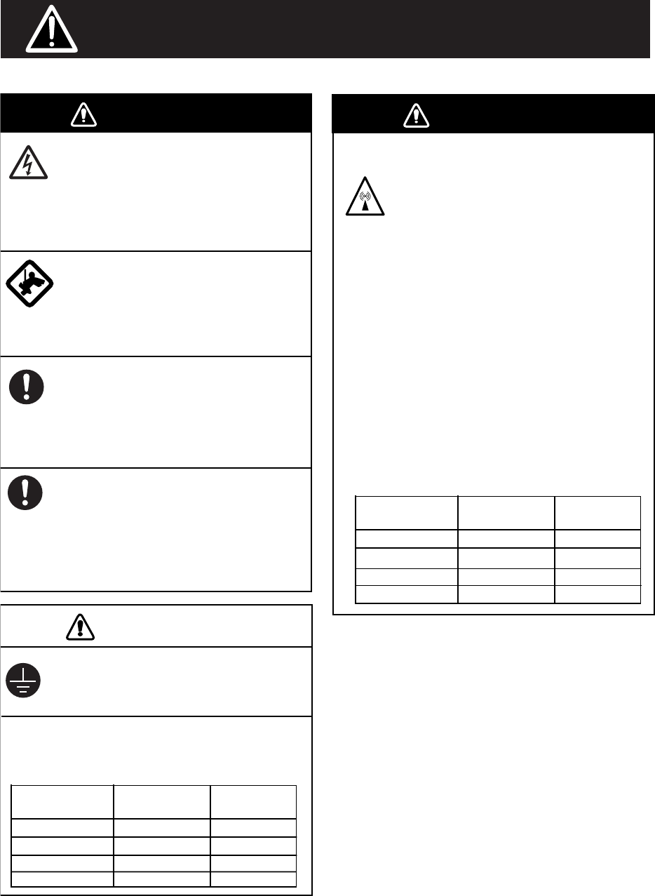
WARNING WARNING
Wear a safety belt and hard hat when
working on the antenna unit.
Serious injury or death can result if
someone falls from the radar mast.
Model Distance to
100 W/m2 point
Distance to
10 W/m2 point
DRS4A Nil 1.20 m
Nil 1.20 m
The radar antenna emits electromagnetic
radio frequency (RF) energy which can be
harmful, particularly to your eyes. Never
look directly into the antenna aperture
from a close distance while the radar is in
operation or expose yourself to the trans-
mitting antenna at a close distance.
Distances at which RF radiation levels of
100 and 10 W/m2 exist are given in the
table below.
Note: If the antenna unit is installed at a
closedistance in front of the wheel house,
your administration may require halt of
transmission within a certain sector of
antenna revolution. This is possible -
Ask your FURUNO representive or dealer
to provide this feature.
CAUTION
Do not open the equipment unless
totally familiar with electrical circuits
and service manual.
Only qualified personnel should work
inside the equipment.
Observe the following compass safe
distance to prevent deviation of a ma
gnetic compass.
Ground the equipment to prevent
electrical shock and mutual
interference.
Construct a suitable service platform
from which to install the antennaunit.
Serious injury or death can result if the
power is left on or is applied while the
equipment is being installed.
Turn off the power at the mains
switch-board before beginning the
installation.
Fire, electrical shock or serious injury can
result if the power is left on or is applied
while the equipment is being installed.
Model Standard Steering
DRS4A 0.80 m 0.50 m
DRS6A 0.85 m 0.55 m
Radio Frequency Radiation Hazard
DRS6A
SAFETY INSTRUCTIONS
DRS2D
DRS4D
1.35 m 0.80 m
1.40 m 0.85 m
DRS2D Nil 0.40 m
0.1 m 1.40 m
DRS4D
ii
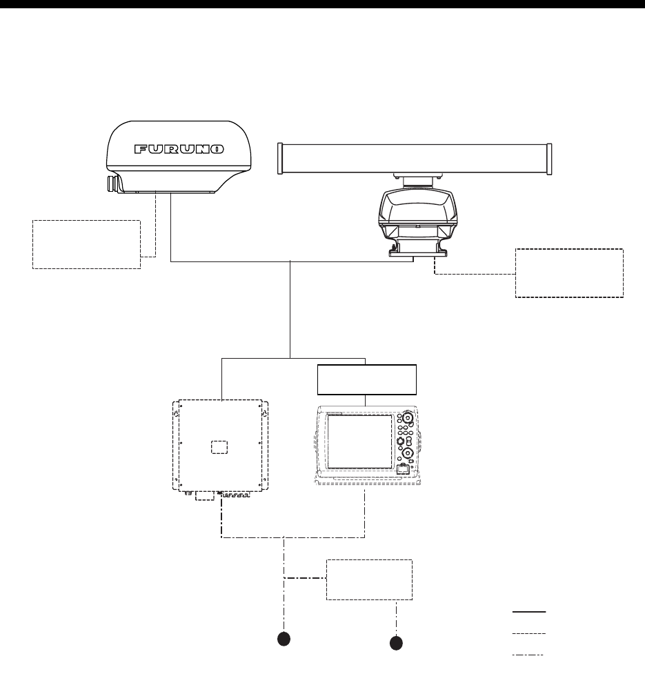
SYSTEM CONFIGURATION
RADAR SENSOR
DRS4A/DRS6A
OR
RECTIFIER
RU-1746B
100/110/220/230 VAC
12-24 VDC
NMEA 2000
(Under development)
: Standard Supply
: Optional Supply
: Local Supply
Multi Function Display BlackBox
MFDBB Multi Function Display
MFD8/12
Power Supply Unit
PSU-012*
*For MFD8 only
NMEA 2000
(Under development)
RADAR SENSOR
DRS2D/DRS4D
iii
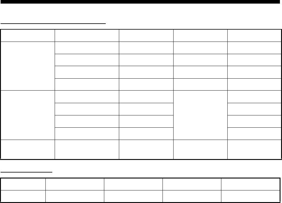
EQUIPMENT LISTS
Standard supply (for DRS4A/6A)
Optional supply
Name Type Code No. Qty Remarks
Radar Sensor XN10A-RSB-118-092 - 1 For DRS4A
XN12A-RSB-118-093 - 1 For DRS6A
DRS2D - 1 Radome
DRS4D - 1 Radome
Two-way Cable MOD-ASW0001-010 1 10 m
MOD-ASW0001-015 15 m
MOD-ASW0001-020 20 m
MOD-ASW0001-030 30 m
Installation Mate-
rials
1 set
Name Type Code No. Qty Remarks
Junction Box J-BOX 1
1
1. MOUNTING
1.1 Mounting Considerations
• The radar sensor is generally installed either on top of the wheelhouse or on the radar mast on
a suitable platform. Locate the radar sensor where there is a good all-round view. Any obstruc-
tion will cause shadow and blind sectors. A mast for instance, with a diameter considerably less
than the horizontal beamwidth of the radiator, will cause only a small blind sector, but a horizon-
tal spreader or crosstrees in the same horizontal plane as the radar sensor would be a much
more serious obstruction; you would need to place the radar sensor well above or below it.
• It is rarely possible to place the radar sensor where a completely clear view in all directions is
available. Thus, you should determine the angular width and relative bearing of any shadow
sectors for their influence on the radar at the first opportunity after fitting.
• A magnetic compass will be affected if the radar sensor is placed too close to it. Observe the
compass safe distances mentioned in the SAFETY INSTRUCTIONS to prevent interference to
a magnetic compass.
• Do not paint the radiator aperture, to ensure proper emision of the radar waves.
• When this radar sensor is to be installed on large vessels, consider the following points:
• The signal cable run between the radar sensor and MFDBB, MFD8 or MFD12 comes in
lengths of 10 m, 15 m, 20 m and 30 m.
• Deposits and fumes from a funnel or other exhaust vent can adversely affect the aerial per-
formance and hot gases may distort the radiator portion. The radar sensor must not be
mounted where the temperature is more than 70°C.
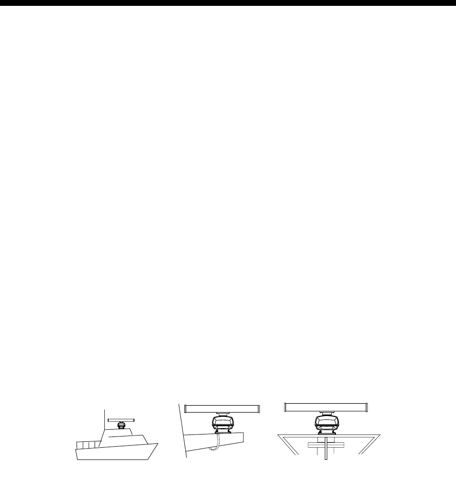
As shown in the figure below, the radar sensor may be installed on the bridge, on a common mast
or on the radar mast.
For DRS4A/6A
(a) On bridge (b) Common mast (c) Radar mast
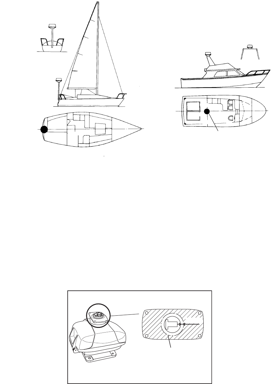
2
For DRS2D/4D
1.2 Mounting Procesure for DRS4A/6A
Referring to the outline drawing at the back of this manual, drill five holes in the mounting platform:
four holes of 15 mm diameter for fixing the radar sensor and one hole of 25-30 mm diameter for
the signal cable.
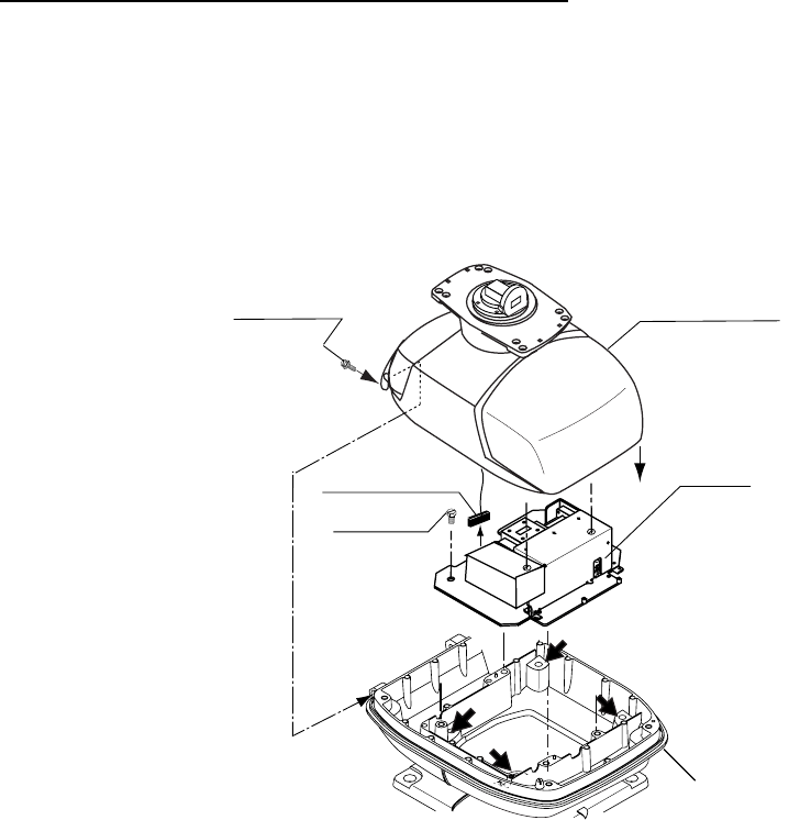
1.2.1 Fastening the radiator to the radiator bracket
1. Remove the radiator cap from the radiator bracket.
2. Coat surface between the antenna radiator and the radiator bracket with silicone sealant as
shown in the figure below.
3. Coat threaded holes on the antenna radiator with silicone sealant.
4. Grease the O-ring and set it to the radiator bracket.
Antenna unit
Antenna unit
Antenna unit
Antenna unit
RADIATOR BRACKET
(top view)
Coat hatched area with
silicone sealant.
10mm
3
5. Coat the hex bolts (4 pcs.) with silicone sealant. Fasten the antenna radiator to the radiator
bracket with the hex bolts, flat washers and spring washers.
1.2.2 Mounting the radar sensor
The radar sensor can be mounted using the fixing holes on the outside (200 x 200 mm) or inside
(140 x 150 mm) the radar sensor.
Using outside fixing holes of radar sensor
Use the hex bolts (supplied) to mount the radar sensor as below.
1. Lay the corrosion-proof rubber mat (supplied) on the mounting platform.
2. Lay the radar sensor on the mounting platform, orienting it as shown below.
Flat washer
Spring washer
Hex bolt
(M8 x 30)
Radiator bracket
Coat bolts with
silicone sealant.
Antenna
radiator
O-ring
Coat threaded
holes with silicone
sealant.
Ground
terminal
Rubber
mat
Bow mark
STERN
BOW
4
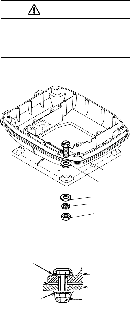
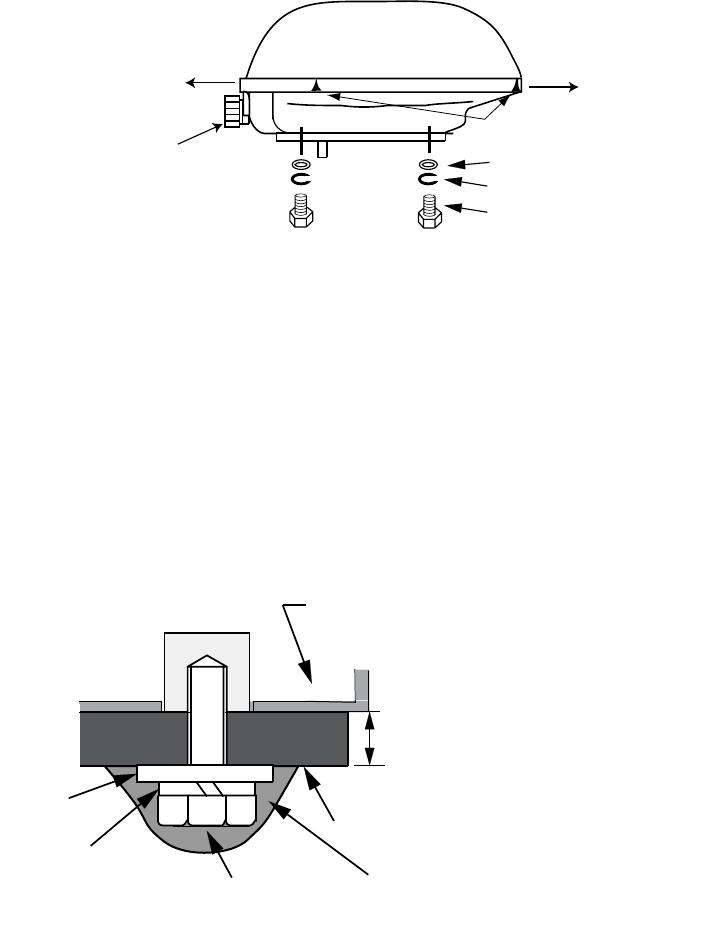
3. Insert four hex bolts (M12 x 60, supplied) and seal washers (φ30, supplied) from the top of the
housing, as shown below.
4. Past flat washers (M12, supplied), spring washers (M12, supplied) and nuts (M12, supplied)
onto hex. bolts. Fasten by tightening nuts. Do not fasten by tightening the hex. bolts; seal
washers may be damaged.
5. Coat flat washers, spring washers, nuts and exposed parts of bolts with anticorrosive sealant.
6. Prepare ground point in mounting platform (within 300 mm of ground terminal on radar sen-
sor) using M6 x 25 bolt, nut and flat washer (supplied).
7. Run the ground wire (RW-4747, 340 mm, supplied) between the ground terminal and ground
point.
CAUTION
Do not lift the radar sensor by the
radiator; lift it by the housing.
The radiator may be damaged.
Hex. bolt
Seal washe
r
Flat washer
Spring washer
Nut
Antenna
unit
Mounting
platform
Silicone
sealant
Flat washer
Rubber mat
Seal washer
5
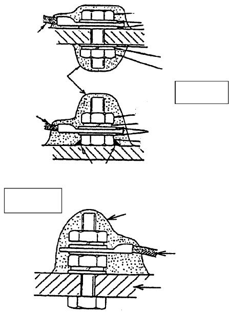
8. Coat ground terminal and ground point with silicone sealant as shown below.
Ground
wire
Hex. bolt
Flat washer
Spring washer
Flat washer
Hex. nut
Silicone
sealant
Hex. nut
Weld here.
Silicone
sealant
Ground
wire
antenna
unit
OR
Flat washer
Spring washer
Ground
wire
GROUND
TERMINAL
GROUND
POINT
Hex. nut
6
Using inside fixing holes of the sensor housing
This method requires removal of the RF unit from the radar sensor to access inside fixing holes.
Use hex bolts, flat washers, spring washers and nuts (local supply) to mount the radar sensor.
1. Unfasten four bolts from the cover to open the radar sensor.
2. Unplug the PCS connector from RF unit.
3. Separate upper chassis from lower chassis by removing two bolts (M8x25).
4. Remove RF unit by unfastening four hex bolts.
5. Lay the corrosion-proof rubber mat (supplied) on the mounting platform.
6. Fasten the lower chassis to the mounting platform with hex bolts, spring washers, flat washers
and nuts (local supply), and then coat flat washers, nuts and exposed parts of bolts with sili-
cone sealant. Cut a slit in the rubber bushing and insert bolt into the bushing. Do not use seal
washers.
7. Remount RF unit.
8. Apply silicone sealant into four outside fixing holes.
9. Do steps 6-8 in “Using outside fixing holes of radar sensor”.
Note: When closing the cover, set the gaskets to grooves in the bottom chassis, then tighten bolts.
RF unit
Hex bolt
4 pcs.
Bolt
M8X25,
2 pcs.
Upper chassis
Lower chassis
PCS connector
7
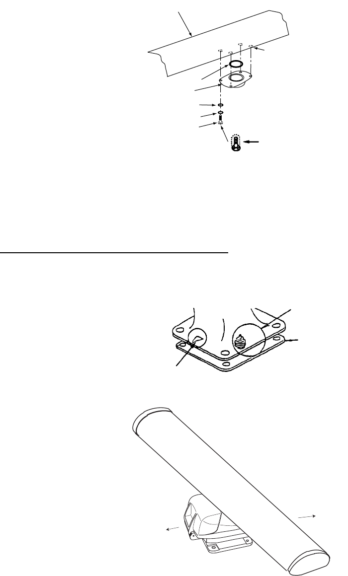
1.3 Mounting Procedure for DRS2D4D
1. Remove mounting hardware at the bottom of the radar sensor, four each of hex bolts
(M10x20), spring washers and flat washers. Save the spring washers and flat washers to use
them to fix the radome base to the platform, at step 3. If the thickness of the mounting platform
is 5 mm or less also save the bolts.
2. Construct a platform (wood, steel or aluminum) 6-10 mm in thickness referring to the outline
drawing at the back of this manual. (A mounting bracket for mounting the radar sensor on a
sailboat mast is optionally available.) Fasten the platform to the mounting location. Next, posi-
tion the base so the cable entrance faces the stern direction.
Note: When drilling holes in the platform, be sure they are parallel with the fore and aft line.
3. Using the hex bolts*, flat washers and spring washers removed at step 1, fastgen the radome
base to the platform. The torque should be between 19.6-24.5Nm.
*If the thickness of the platfoirm is 6-10 mm, use M10x25 bolts (supplied). For thicker platform,
use locally supplied bolts.
Flat washer
Spring washer
Hex bolt (M10 x 20)
Screws
two screws on other side
Bow
Stern
Cable entry
Flat
washer
Antenna base
assy.
Spring
washer
Platform
Hex bolt Apply silicone sealant.
(M10 x 25
or M10 x 20)
Transceiver
module
5 mm or under: M10x20
6-10 mm: M10x25
over 10 mm: localy supplied bolts
8
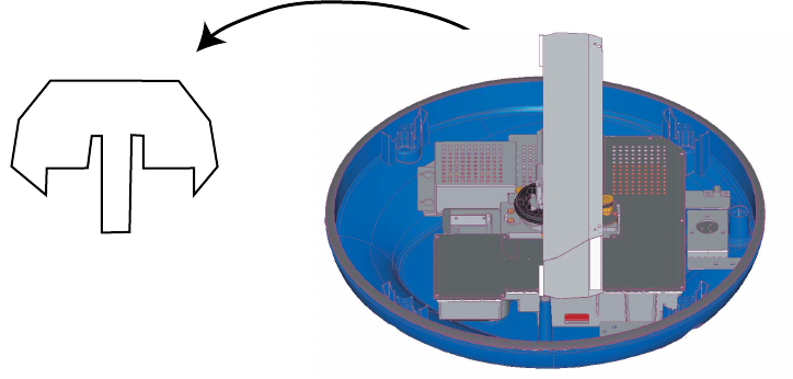
4. Unfasten four screws to remove the cover. Discard the packing material in the radome.
5. Mount the cover tentatively. Wiring requires the removing the cover at Chapter 2.
Remove and discard
the packing material.
9
2. WIRING
Only the two-way cable MOD-ASW0001 runs from the MFDBB, MFD8, MFD12 or PSU-12 to the
radar sensor. In order to minimize the chance of picking up electrical interference, avoid where
possible routing the two-way cable near other onboard electrical equipment. Pass the cable
through the hole in the radar sensor and apply sealing compound around the hole for waterproof-
ing.
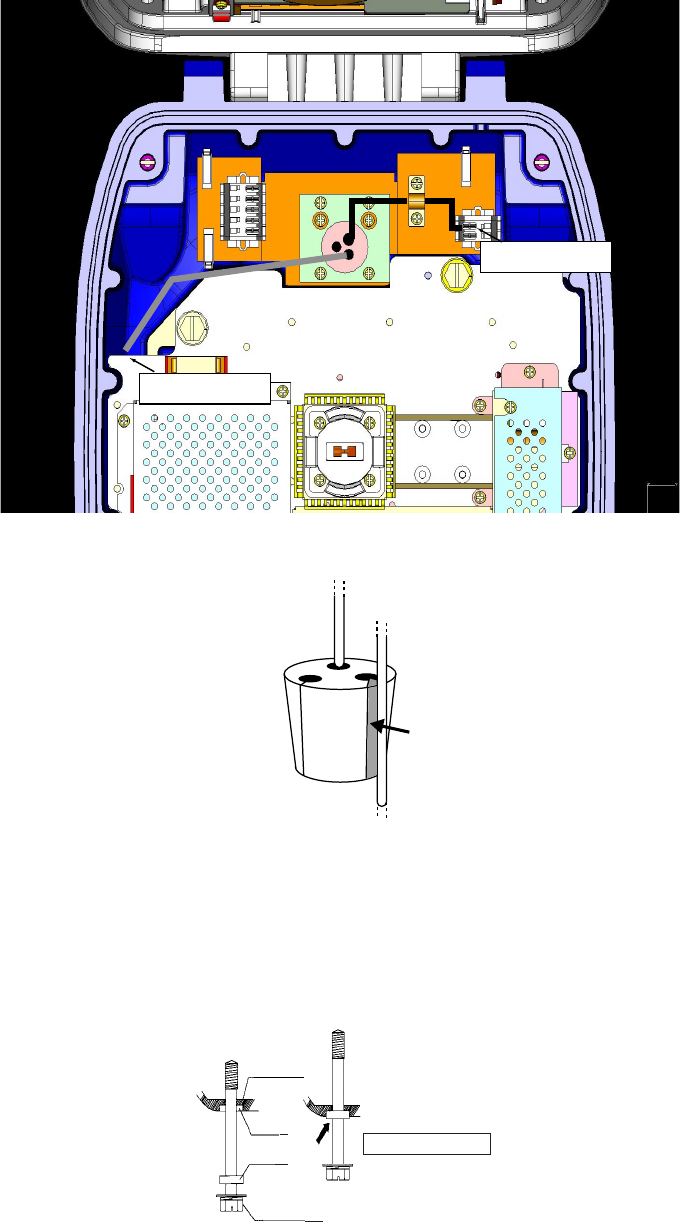
2.1 Wiring of DRS4A/6A
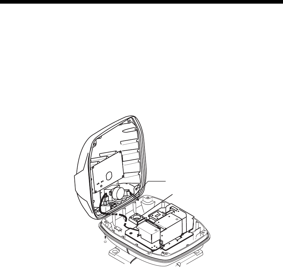
1. Open the radar sensor cover by loosening four bolts, and fix the stay.
2. Unfasten the cable gland assembly (plate and gasket).
3. Pass the two-way cable MOD-ASW0001 through the bottom.
4. Fasten the shield of the cable with the cable clamp in the radar sensor, and then connect the
connector of power cable to the power terminal (white: +, black: -).
Stay
Cable gland
Bolt
10
5. Attach the RJ-45 connector of the two-way cable to the LAN terminal in the radar sensor.
6. Push cables of the two-way cable into the slits of the gasket inside the radar sensor as below.
7. Push the gasket into the hole at the bottom of the radar sensor, then fasten four pan head
screws to fix the plate to the sensor.
8. Release the stay and close the cover.
Note: When closing the cover, set the gaskets to grooves in the bottom chassis, then tigten bolts.
Power terminal
LAN terminal
BOTTOM
CHASSIS
GASKET
GROOVE
HEX BOLT
Torque : 9.8 ±0.1 N m
.
11
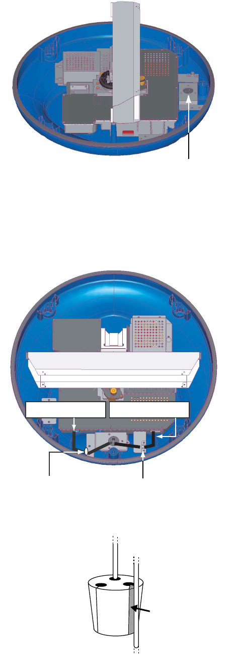
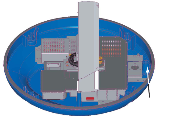
2.2 Wiring of DRS2D/4D
1. Unfasten three screws to remove the fixing plate for the gasket at the bottom of the radar sen-
sor.
2. Remove the gasket, and then pass the two-way cable MOD-ASW0001 through the bottom.
3. Fasten the shield of the cable with the cable clamp in the radar sensor, and then connect the
connector of power cable to the power terminal (white: +, black: -).
4. Attach the RJ-45 connector of the two-way cable to the LAN terminal in the radar sensor.
5. Push cables of the two-way cable into the slits of the gasket inside the radar sensor as below.
Fixing plate
(for gasket)
Power terminalLAN terminal
Fix the cable
with this clamp.
Fix the cable with
this grommet.
12
Note 1: Bend cables of the two way cable at the height lower than moisture hole so that the an-
tenna radiator does not hit these cables.
Note 2: If the two-way cable meets to the platform near the radar sensor base, wind vinyl tape
around cable at the bending location.
6. Confirm that the rubber gasket is properly positioned and that the triangle mark on the cover is
aligned with the triangle mark on the mounting base, then tighten the fixing screws for the
cover.
Moisture hole

13
3. ADJUSTMENT
This section provides the information necessary for setting and adjusting the radar sensor, which
is carried out from the menu.
3.1 Selecting Radar Source
1. Open the Radar Installation menu.
2. Choose “Radar Source” to show the menu options window.
3. Choose “DRS4A” or DRS6A” as applicable.
4. Close the Radar Source options window.
3.2 Heading Alignment
You have mounted the radar sensor facing straight ahead in the direction of the bow. Therefore,
a small but conspicuous target dead ahead visually should appear on the heading line (zero de-
grees).
In practice, you will probably observe some small error on the display because of the difficulty in
achieving accurate initial positioning of the radar sensor. The following adjustment wil compen-
sate for this error.
1. Choose “Heading Alignment” from the menu.
2. Select a stationary target echo at a range between 0.125 and 0.25 nm, preferably near the
heading line.
3. Place the cursor on the indication “EBL 1” or “EBL 2” at the bottom left corner, and then press
the left-button key at the center of the cursorpad to show the EBL.
4. Rotate the RotoKey to bisect the target echo with the EBL.
5. Press the left-button key.
6. As a final test, move the boat towards a small buoy and confirm that the buoy shows up dead
ahead on the radar when it is visually dead ahead.
3.3 Setting the Antenna Height
1. Select “ANTENNA HEIGHT” from the menu.
2. Select the height of the radar sensor above the water surface.
Pub.No. IME-35670 Z