Furuno USA 9ZWRTR091A Marine Radar User Manual
Furuno USA Inc Marine Radar
users manual

www.furuno.co.jp
Installation Manual
RADAR SENSOR
DRS2D/DRS4D/
DRS4A/DRS6A/DRS12A/DRS25A
SAFETY INSTRUCTIONS ............................................................................ i
SYSTEM CONFIGURATION ....................................................................... ii
EQUIPMENT LISTS.................................................................................... iv
1. MOUNTING ............................................................................................ 1
1.1 Mounting Considerations..............................................................................................1
1.2 Mounting Procedure for DRS2D/4D .............................................................................2
1.3 Mounting Procedure for DRS4A/6A/12A/25A ...............................................................3
1.4 Mounting of Power Supply Unit PSU-013 (for DRS25A)/PSU-012 (Option) ................8
2. WIRING .................................................................................................. 9
2.1 Wiring inside DRS2D/4D ............................................................................................12
2.2 Wiring inside DRS4A/6A/12A/25A ..............................................................................16
2.3 Wiring inside Power Supply Unit PSU-013 (for DRS25A) ..........................................20
2.4 Wiring inside Power Supply Unit PSU-012 (Option)...................................................21
PACKING LISTS...................................................................................... A-1
OUTLINE DRAWINGS............................................................................. D-1
INTERCONNECTION DIAGRAMS.......................................................... S-1
i
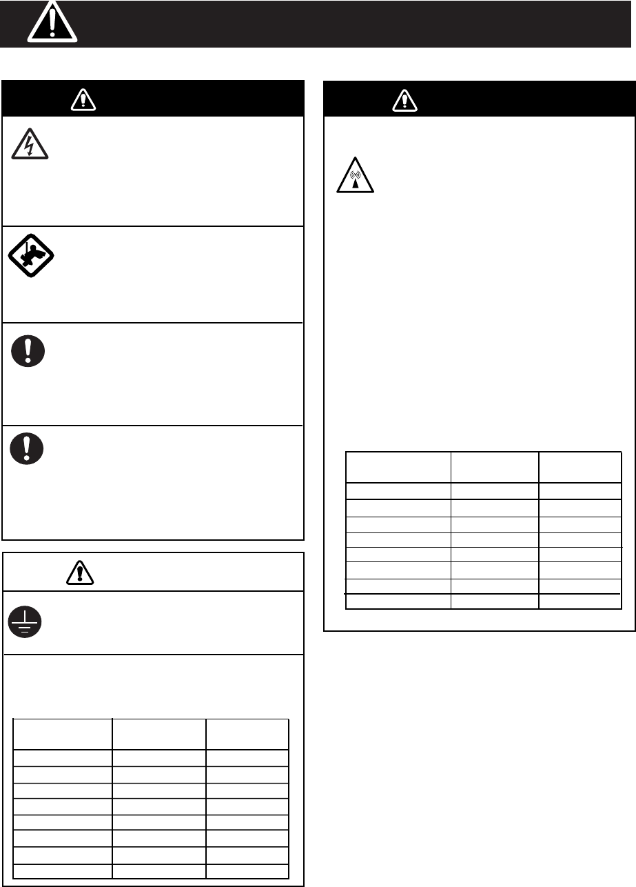
WARNING WARNING
Wear a safety belt and hard hat when
working on the antenna unit.
Serious injury or death can result if
someone falls from the radar mast.
Model Distance to
100 W/m2 point Distance to
10 W/m2 point
DRS4A Nil 1.20 m
Nil 1.20 m
The radar antenna emits electromagnetic
radio frequency (RF) energy which can be
harmful, particularly to your eyes. Never
look directly into the antenna aperture
from a close distance while the radar is in
operation or expose yourself to the trans-
mitting antenna at a close distance.
Distances at which RF radiation levels of
100 and 10 W/m
2
exist are given in the
table below.
Note: If the antenna unit is installed at a
close distance in front of the wheel house,
your administration may require halt of
transmission within a certain sector of
antenna revolution. This is possible -
Ask your FURUNO representive or dealer
to provide this feature.
CAUTION
Do not open the equipment unless
totally familiar with electrical circuits
and service manual.
Only qualified personnel should work
inside the equipment.
Observe the following compass safe
distance to prevent deviation of a ma
gnetic compass.
Ground the equipment to prevent
electrical shock and mutual
interference.
Construct a suitable service platform
from which to install the antenna unit.
Serious injury or death can result if the
power is left on or is applied while the
equipment is being installed.
Turn off the power at the mains
switch-board before beginning the
installation.
Fire, electrical shock or serious injury can
result if the power is left on or is applied
while the equipment is being installed.
Model Standard Steering
DRS4A 0.80 m 0.50 m
DRS6A 0.85 m 0.55 m
Radio Frequency Radiation Hazard
DRS6A
SAFETY INSTRUCTIONS
DRS12A
DRS2D Nil 0.40 m
0.10 m 1.40 m
DRS4D
DRS4D
1.40 m 0.85 m
DRS2D 1.35 m 0.80 m
0.20 m 2.40 m
DRS12A (XN12A)
DRS12A (XN13A) 0.20 m 1.90 m
1.15 m 0.70 m
PSU-012
0.30 m 0.30 m
PSU-013
0.30 m 0.30 m
DRS25A 1.00 m 0.60 m
0.50 m 5.30 m
DRS25A (XN12A)
DRS25A (XN13A) 0.40 m 4.40 m
ii
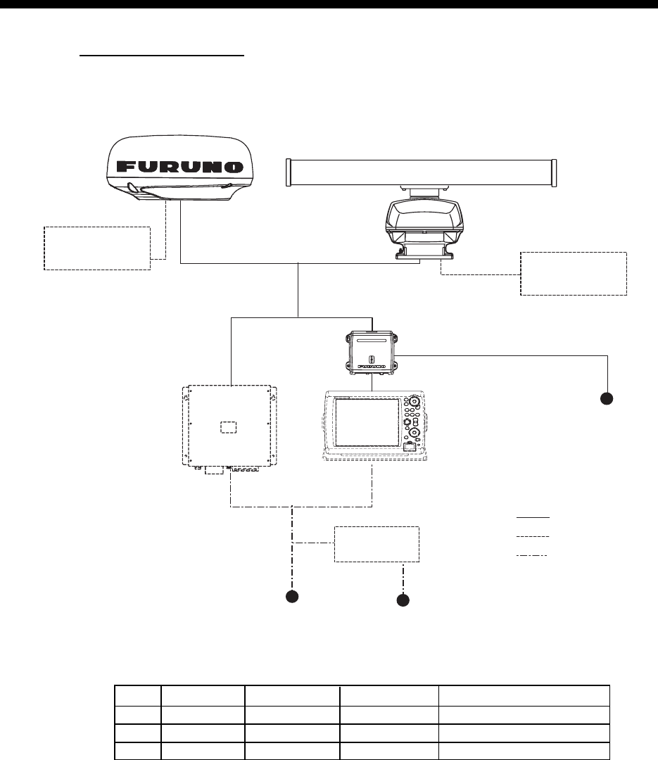
SYSTEM CONFIGURATION
DRS2D/4D/4A/6A/12A
RADAR SENSOR
DRS4A/DRS6A/DRS12A
OR
RECTIFIER
RU-1746B
100/110/220/230 VAC
12-24 VDC
NMEA 2000
Equipment
: Standard Supply
: Optional Supply
: Local Supply
Multi Function Display BlackBox
MFDBB Multi Function Display
MFD8/12
Power Supply Unit
PSU-012*
*The power supply unit PSU-012 is necessary in the combination of radar sensor and MFD.
NMEA 2000
Equipment
RADAR SENSOR
DRS2D/DRS4D
MFD8
MFD12
MFDBB
DRS2D/4D DRS4A DRS6A DRS12A (future development)
NO
NO
NO
NO
NO
NO
NO
YES YES YES
YES
NO
12-24 VDC
iii
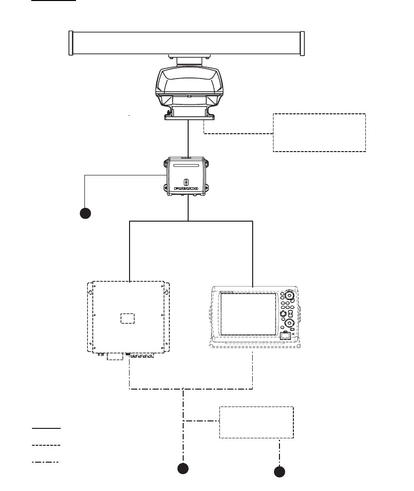
DRS25A
RADAR SENSOR
DRS25A
OR
RECTIFIER
RU-1746B
100/110/220/230 VAC
12-24 VDC
NMEA 2000
Equipment
: Standard Supply
: Optional Supply
: Local Supply
Multi Function
Display BlackBox
MFDBB
Multi Function Display
MFD8/12
Power Supply Unit
PSU-013
12-24 VDC

iv
EQUIPMENT LISTS
Standard supply
Name Type Code No. Qty Remarks
Radar Sensor XN10A-RSB-118-092 - 1 For DRS4A, w/CP03-32601
XN12A-RSB-118-093 1 For DRS6A, w/CP03-32601
XN12A-RSB-118-094 - 1 For DRS12A, 1255 mm,
w/CP03-32601
XN13A-RSB-118-094 1 For DRS12A, 1795 mm,
w/CP03-32601
XN12A-RSB-118-095 - 1 For DRS25A, 1255 mm, w/CP03-
32601
XN13A-RSB-118-095 - 1 For DRS25A, 1795 mm, w/CP03-
32601
DRS2D - 1 Radome, 2 kW,
w/CP03-32101
DRS4D - 1 Radome, 4 kW,
w/CP03-32101
Power Supply
Unit
PSU-013 - 1 For DRS25A, w/SP03-16101 and
CP03-32700
Installation
Materials
CP03-32101 001-025-270 1 set For DRS2D/4D
CP03-32601 001-025-780 1 set For DRS4A/6A/12A/25A
CP03-32200 000-011-720 1 Two-way cable, MOD-ASW0001-
100+, 10 m, for DRS2D/4D/4A/6A/12A
CP03-32300 000-011-721 Two-way cable, MOD-ASW0001-
150+, 15 m, for DRS2D/4D/4A/6A/12A
CP03-32400 000-011-722 Two-way cable, MOD-ASW0001-
200+, 20 m, for DRS2D/4D/4A/6A/12A
CP03-32500 000-011-723 Two-way cable, MOD-ASW0001-
300+, 30 m, for DRS2D/4D/4A/6A/12A
CP03-32800 000-011-990 Two-way cable, MOD-ASW0002-
100+, 10 m, for DRS25A
CP03-32810 000-011-991 Two-way cable, MOD-ASW0002-
150+, 15 m, for DRS25A
CP03-32820 000-011-992 Two-way cable, MOD-ASW0002-
200+, 20 m, for DRS25A
CP03-32830 000-011-993 Two-way cable, MOD-ASW0002-
300+, 30 m, for DRS25A

v
Optional supply
Name Type Code No. Qty Remarks
Power Supply
Unit
PSU-012 - 1 set
Gasket OP03-203 001-025-290 1 For DRS2D/4D, φ10 NMEA2000
cable
OP03-205 001-025-790 For DRS4A/6A, φ10 NMEA2000
cable
OP03-206 001-035-290 For DRS25A, φ10 NMEA2000 cable
Resister Assy OP03-204 001-025-300 1 For NMEA2000 connection with a unit
Joint Box TL-CAT-012 000-167-140-10 1 For LAN cable extension
LAN Cable MOD-Z072-020+ 000-167-175-10 1 2 m
MOD-Z072-050+ 000-167-176-10 1 5 m
MOD-Z072-100+ 000-167-177-10 1 10 m
Cable Assy M12-05BFFM-010 000-167-965-10 1 NMEA2000, φ6, w/connector, 1 m
M12-05BFFM-020 000-167-966-10 1 NMEA2000, φ6, w/connector, 2 m
M12-05BFFM-060 000-167-967-10 1 NMEA2000, φ6, w/connector, 6 m
CB-05BFFM-010 000-167-971-10 1 NMEA2000, φ10, w/connector, 1 m
CB-05BFFM-020 000-167-972-10 1 NMEA2000, φ10, w/connector, 2 m
CB-05BFFM-060 000-167-973-10 1 NMEA2000, φ10, w/connector, 6 m
1
1. MOUNTING
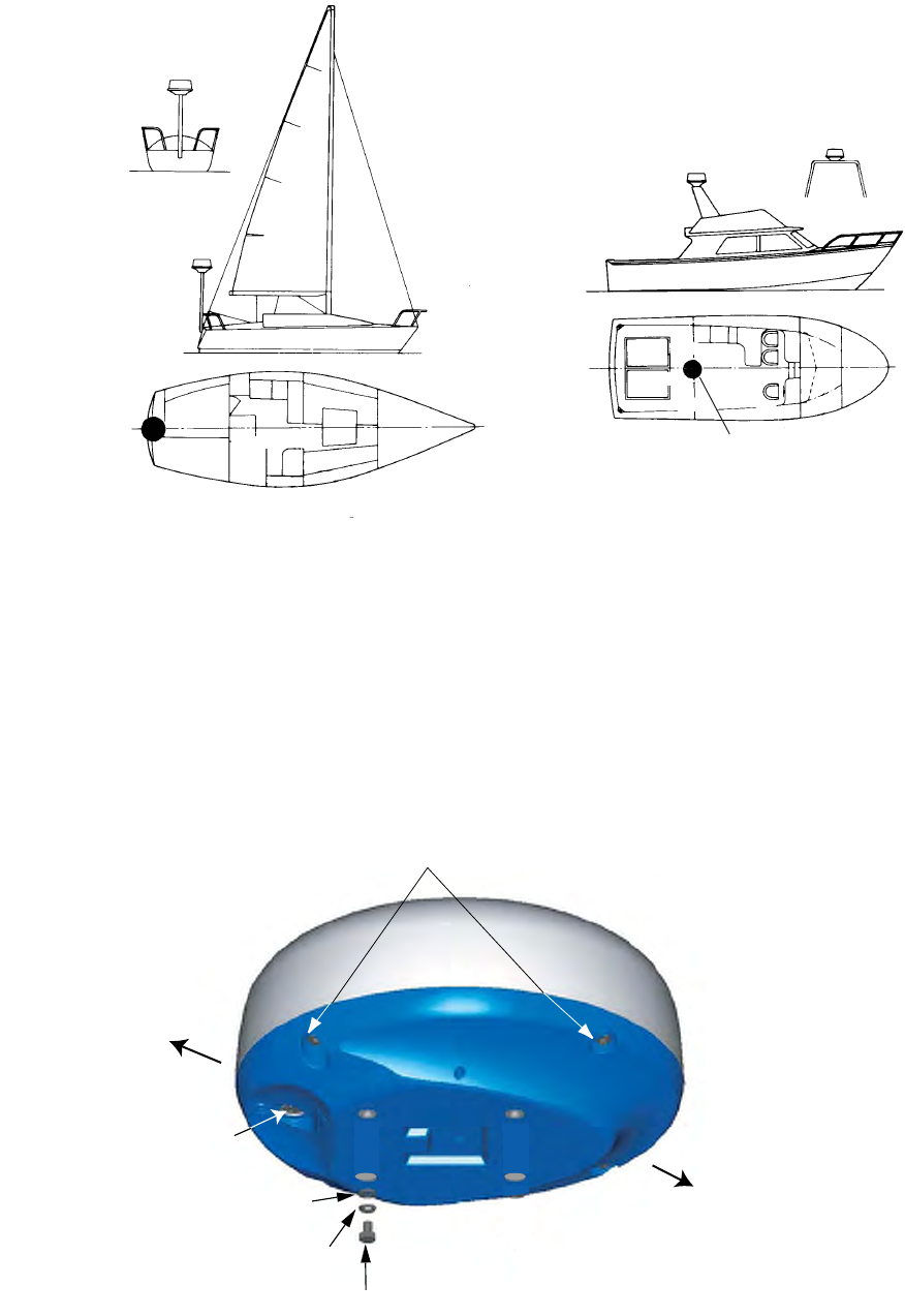
1.1 Mounting Considerations
• The radar sensor is generally installed either on top of the wheelhouse or on the radar mast on
a suitable platform. Locate the radar sensor where there is a good all-round view. Any obstruc-
tion will cause shadow and blind sectors. A mast for instance, with a diameter considerably less
than the horizontal beamwidth of the radiator, will cause only a small blind sector, but a horizon-
tal spreader or crosstrees in the same horizontal plane as the radar sensor would be a much
more serious obstruction; you would need to place the radar sensor well above or below it.
• It is rarely possible to place the radar sensor where a completely clear view in all directions is
available. Thus, you should determine the angular width and relative bearing of any shadow
sectors for their influence on the radar at the first opportunity after fitting.
• A magnetic compass will be affected if the radar sensor is placed too close to it. Observe the
compass safe distances mentioned in the SAFETY INSTRUCTIONS to prevent interference to
a magnetic compass.
• Do not paint the radiator aperture and radome to ensure proper emision of the radar waves.
• When this radar sensor is to be installed on large vessels, consider the following points:
• The two-way cable run between the radar sensor and MFDBB, MFD8, MFD12 or PSU-012
comes in lengths of 10 m, 15 m, 20 m or 30 m.
• Deposits and fumes from a funnel or other exhaust vent can adversely affect the aerial per-
formance and hot gases may distort the radiator portion. The radar sensor must not be
mounted where the temperature is more than 55 degrees centigrade.
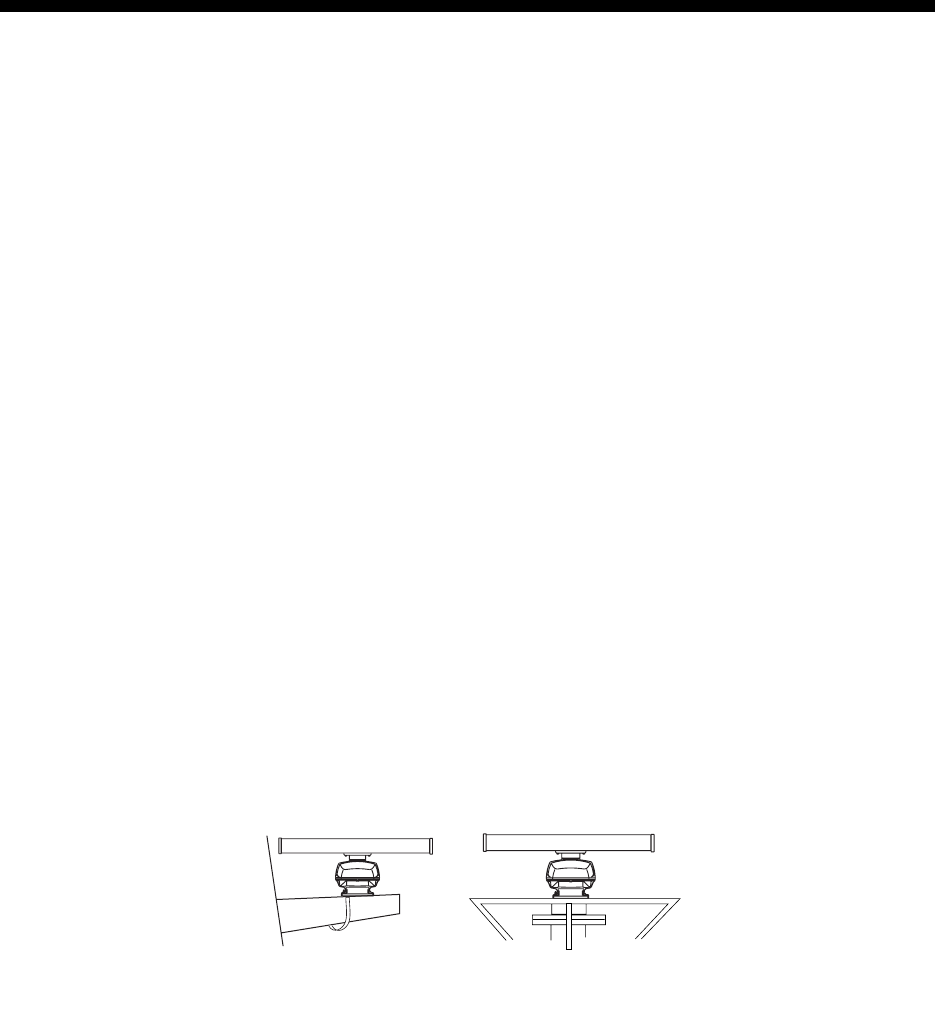
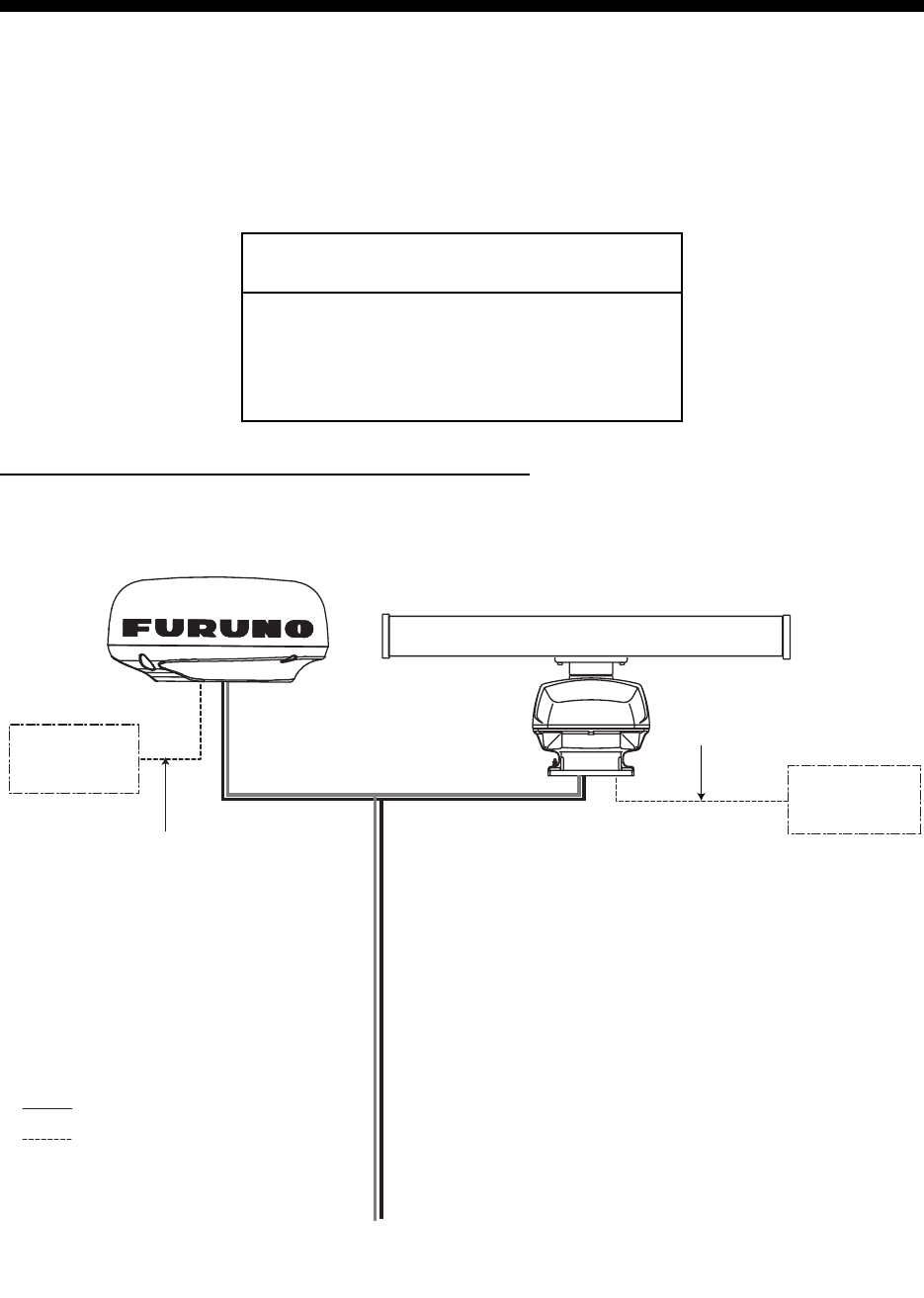
As shown in the figure below, the radar sensor may be installed on a common mast or on the radar
mast.
For DRS4A/6A/12A
(a) Common mast (b) Radar mast
2
For DRS2D/4D
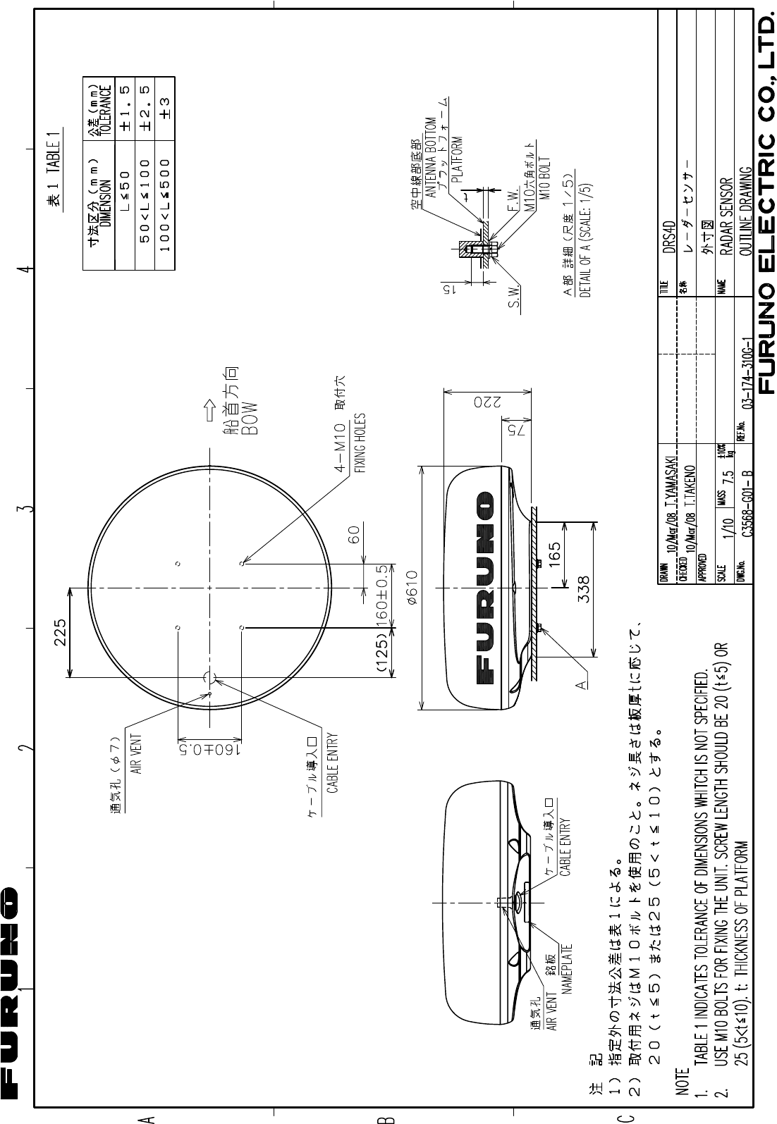
1.2 Mounting Procedure for DRS2D/4D
1. Remove mounting hardware at the bottom of the radar sensor, four each of hex bolts
(M10x20), spring washers and flat washers. Save the spring washers and flat washers to use
them to fix the radome base to the platform, at step 3. If the thickness of the mounting platform
is 5 mm or less, also save the bolts.
2. Construct a platform (steel or aluminum) 6-10 mm in thickness referring to the outline drawing
at the back of this manual. Fasten the platform to the mounting location. Next, position the
base so the cable entrance is facing the stern.
Note: When drilling holes in the platform, be sure they are parallel with the fore and aft line.
Radar sensor
Radar sensor
Radar sensor
Radar sensor
Screws
(two screws on other side)
Stern
Bow
Cable entry
Hex bolt (M10 x 20)
Spring washer
Flat washer
3
3. Use the hex bolts*, flat washers and spring washers removed at step 1, and fasten the
radome base to the platform. The torque should be between 19.6-24.5Nzm.
*If the thickness of the platform is 6-10 mm, use M10x25 bolts (supplied). For thicker platform, use
locally supplied bolts.
4. Mount the cover tentatively. The cover is opened for wiring at Chapter 2.
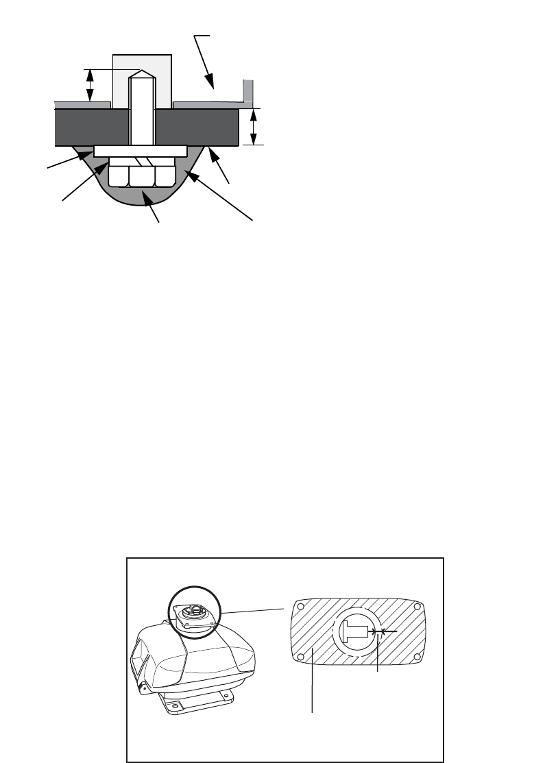
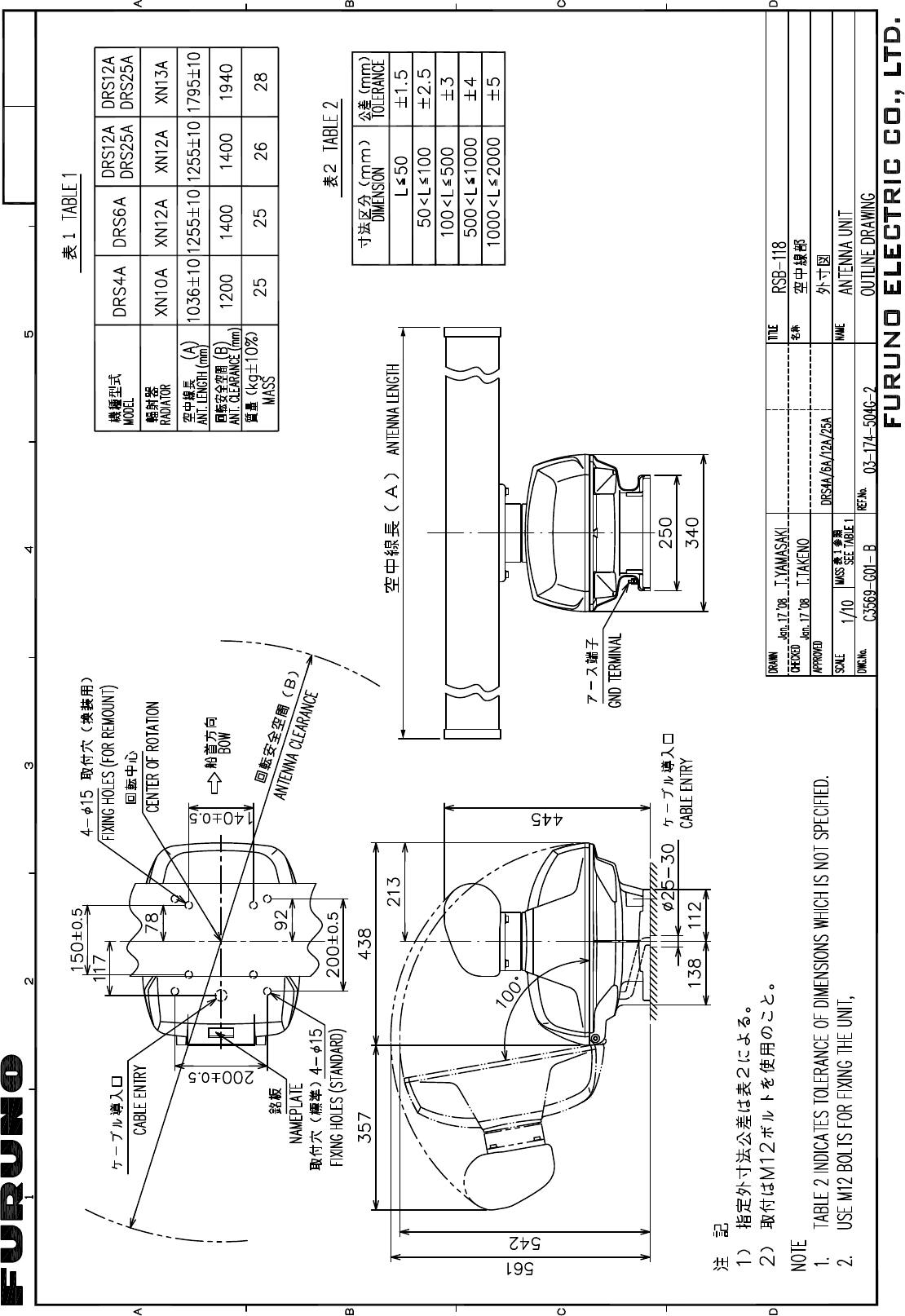
1.3 Mounting Procedure for DRS4A/6A/12A/25A
Refer to the outline drawing at the back of this manual, and drill five holes in the mounting platform:
four holes of 15 mm in diameter for fixing the radar sensor and one hole of 25-30 mm in diameter
for the signal cable. The outline drawing shows two cable entrance holes, one on the radar sensor
and one on the rubber mat. Use only the one on the rubber mat.
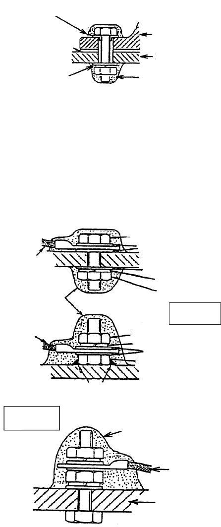
1.3.1 Fastening the radiator to the radiator bracket
1. Remove the radiator cap from the radiator bracket.
2. Coat the surface of the radiator bracket with silicone sealant as shown in the figure below.
3. Coat threaded holes on the antenna radiator with silicone sealant.
4. Grease the O-ring and set it to the radiator bracket.
Flat
washer
Antenna base
assy.
Spring
washer
Platform
Hex bolt Apply silicone sealant.
(M10 x 25
or M10 x 20)
Transceiver
module
5 mm or under: M10x20 (local supply)
6-10 mm: M10x25 (supplied)
over 10 mm: locally supplied bolts
As for length, use the bolt
the "L" shown in the figure
in left becomes 10 to 15 mm.
L
RADIATOR BRACKET
(top view)
Coat hatched area with
silicone sealant.
10mm
(Do not coat.)
4
5. Coat the hex bolts (4 pcs.) with silicone sealant. Fasten the antenna radiator to the radiator
bracket with the hex bolts, flat washers and spring washers supplied with the radiator Then,
apply silicone sealant around the junction part between the radiator and bracket.
6. Apply silicone sealant to holes to prevent water ingress.
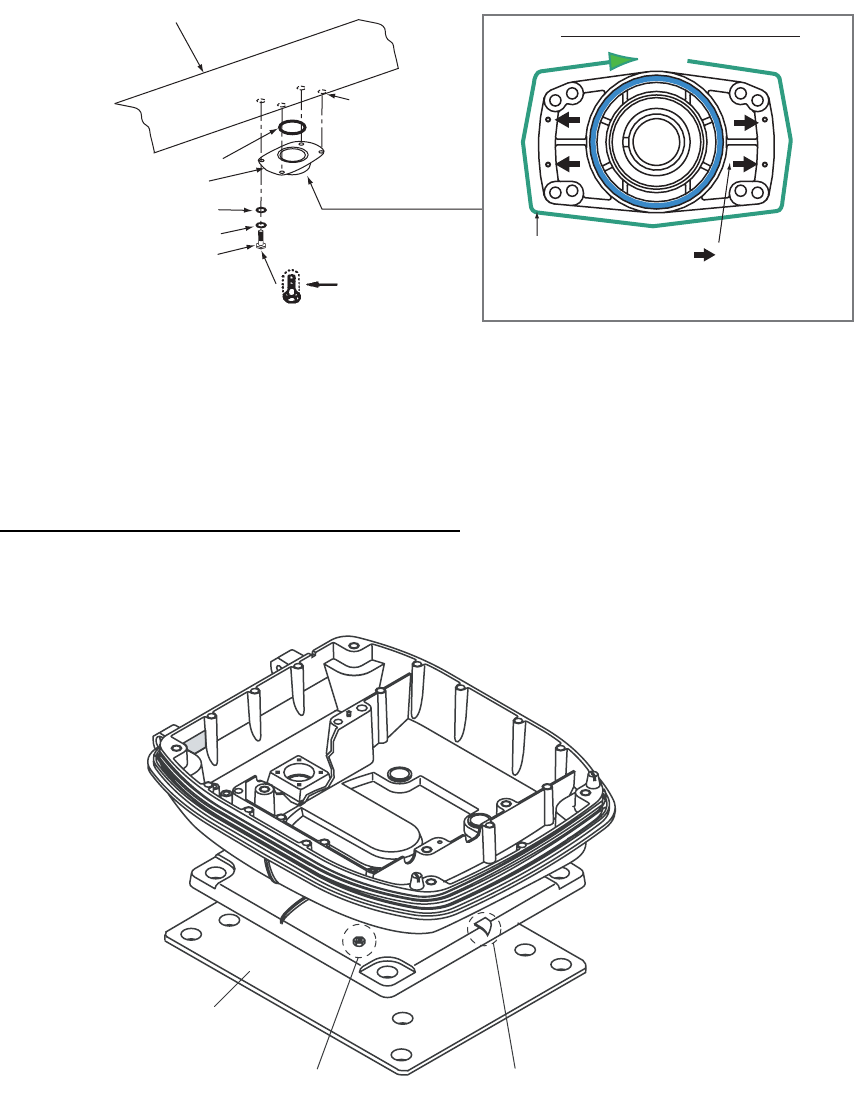
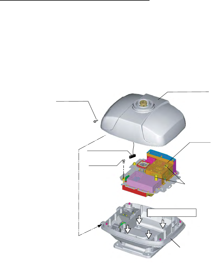
1.3.2 Mounting the radar sensor
The radar sensor can be mounted using the fixing holes on the outside (200 x 200 mm) or inside
(140 x 150 mm) the radar sensor.
Using outside fixing holes of radar sensor
Use the hex bolts (supplied) to mount the radar sensor as below.
1. Lay the corrosion-proof rubber mat (supplied) on the mounting platform.
Flat washer
Spring washer
Hex bolt
(M8 x 30)
Radiator bracket
Coat bolts with
silicone sealant.
Antenna
radiator
O-ring
Coat threaded
holes with
silicone sealant.
Radiator bracket, bottom view
(four): Holes
where to apply
silicone sealant.
Apply silicone sealant
around the joint part
with the antenna
radiator.
Rubber mat
Ground terminal Bow mark
5
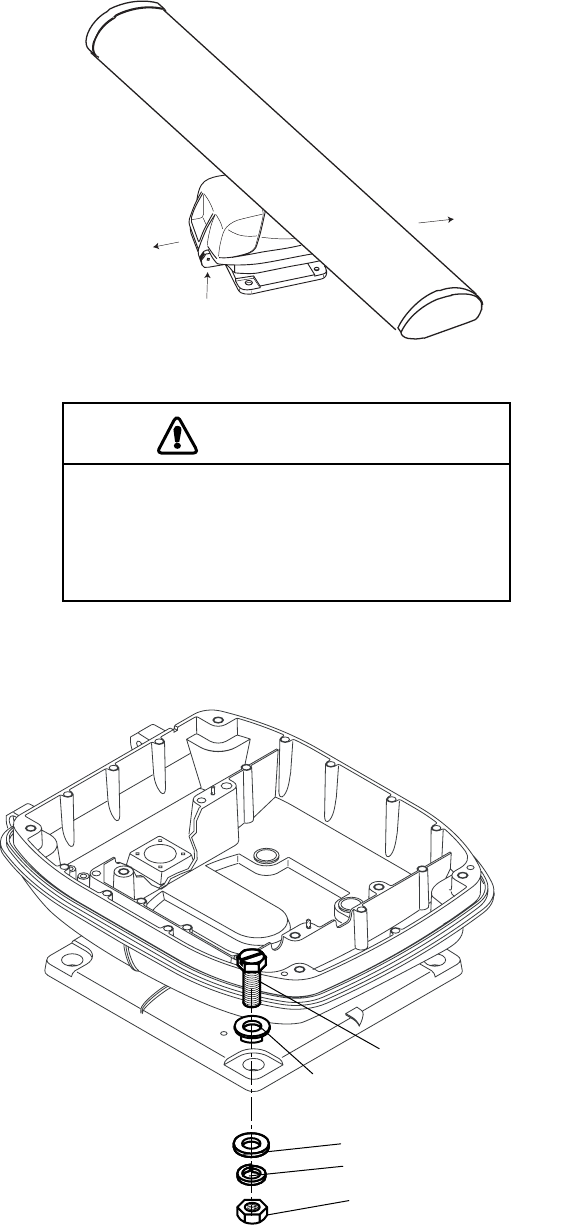
2. Lay the radar sensor on the mounting platform, orienting it as shown below. (The hinges must
face toward the stern.)
3. Insert four hex bolts (M12 x 60, supplied) and seal washers (φ30, supplied) from the top of the
housing, as shown below.
STERN
BOW
Hinge
CAUTION
Do not lift the radar sensor by the
radiator; lift it by the housing.
The radiator may be damaged.
Hex. bolt
Seal washer
(Face projecting part down.)
Flat washer
Spring washer
Nut
6
4. Pass flat washers (M12, supplied), spring washers (M12, supplied) and nuts (M12, supplied)
onto hex. bolts. Fasten by tightening nuts. Do not fasten by tightening the hex. bolts; seal
washers may be damaged.
5. Coat flat washers, spring washers, nuts and exposed parts of bolts with anticorrosive sealant.
6. Prepare ground point in mounting platform (within 300 mm of ground terminal on radar sen-
sor) using M6 x 25 bolt, nut and flat washer (supplied).
7. Run the ground wire (RW-4747, 340 mm, supplied) between the ground terminal and ground
point.
8. Coat ground terminal and ground point with silicone sealant as shown below.
Antenna
unit
Mounting
platform
Silicone
sealant
Flat washer
Rubber mat
Seal washer
Ground
wire
Hex. bolt
Flat washer
Spring washer
Flat washer
Hex. nut
Silicone
sealant
Hex. nut
Weld here.
Silicone
sealant
Ground
wire
antenna
unit
OR
Flat washer
Spring washer
Ground
wire
GROUND
TERMINAL
GROUND
POINT
Hex. nut
7
Using inside fixing holes of the sensor housing
If this radar is replacing a FURUNO radar whose mounting dimensions are the same as this one
(140 x 150 mm), it may be possible to use its mounting platform. This method requires removal of
the RF unit from the radar sensor to access inside fixing holes. Use hex bolts, flat washers, spring
washers and nuts (local supply) to mount the radar sensor.
1. Unfasten four bolts from the cover to open the radar sensor.
2. Unplug the PCS connector from RF unit.
3. Separate upper chassis from lower chassis by removing two bolts (M8x25).
4. Remove RF unit by unfastening two hex bolts and two fixing bolt.
For DRS12A/25A, unfasten four hex bolts, not two fixing bolts, to remove the RF unit.
5. Lay the corrosion-proof rubber mat (supplied) on the mounting platform.
6. Fasten the lower chassis to the mounting platform with hex bolts, spring washers, flat washers
and nuts (local supply), and then coat flat washers, nuts and exposed parts of bolts with sili-
cone sealant. Cut a slit in the rubber bushing and insert bolt into the bushing. Do not use seal
washers.
7. Remount RF unit.
8. Coat outside fixing holes with silicone sealant and then attach caps (supplied) to holes.
9. Do steps 6-8 on page 6.
Bolt
M8x25,
2 pcs.
Inside fixing holes
RF unit
Upper chassis
PCS connector
Hex bolt
2 pcs.
Fixing bolt
(2 pcs.)
Lower chassis
(Example: DRS4A/6A)
8
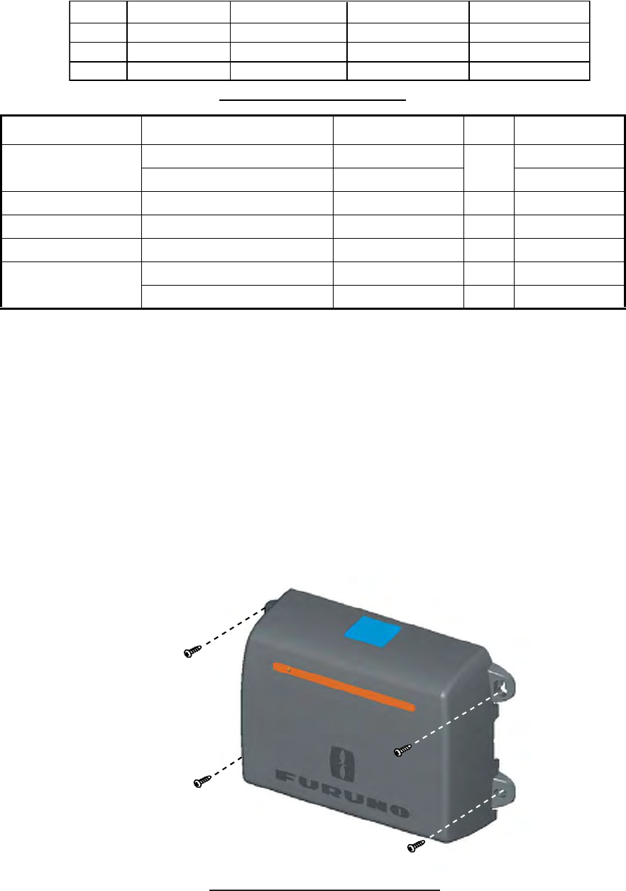
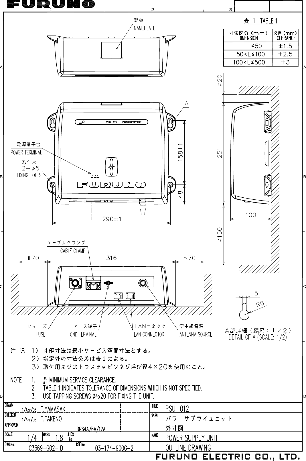
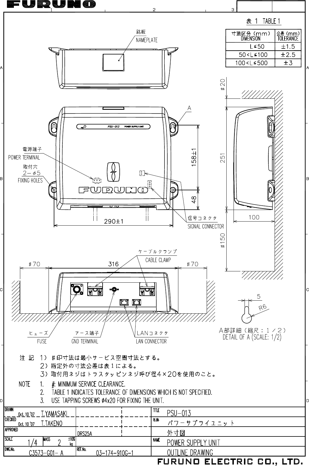
1.4 Mounting of Power Supply Unit
PSU-013 (for DRS25A)/PSU-012 (Option)
For combinations shown below, the optional power supply unit PSU-012 (Code No.: 000-011-756)
is necessary. The PSU-013 is required for any DRS25A installation.
*Note: The power supply unit is shipped with 15A fuse. Replace fuse with 10A when using the unit
with 24V ship’s battery.
The power supply unit can be installed almost anywhere provided the following conditions are met:
• Location is dry, well ventilated.
• Sufficient maintenance space is available.
• Installated within 2, 5 or 10 m (2 and 10 m: optional supply) from the multi function display.
Do not install the power supply unit on the overhead; install it on the deck or bulkhead. Use four
tapping screws (4x20, supplied) to fasten the power supply unit.
Contents of PSU-0012/013
Name Type Code No. Qty Remarks
Power supply unit PSU-012 - 1
PSU-013 - for DRS25A
Cable assy VL3P-VV-S2X2C-AA050 000-152-217-10 1 5 m
LAN cable MOD-Z072-050+ 000-167-176-10 1 5 m, standard
Self-tapping screw 4x20, SUS304 000-158-850-10 4
Fuse* FGB0 250V 10A 000-155-839-10 2 For 24 VDC
FGB0 250V 15A 000-157-874-10 2 For 12 VDC
MFD8
MFD12
MFDBB
DRS2D/4D DRS4A DRS6A DRS12A
NO
NO
NO
NO
NO
NO
NO
YES YES YES
YES
NO
Self-tapping screw
(4x20, 4 pcs.)
Power supply unit PSU-012/013
9
2. WIRING
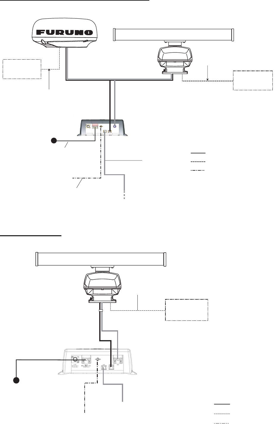
The MFDBB, MFD8, MFD12 or PSU-012 connects to the radar sensor with the two-way cable
MOD-ASW0001 (MOD-ASW0002 for DRS25A).In order to minimize the chance of picking up
electrical interference, avoid where possible routing the two-way cable near other onboard elec-
trical equipment. After passing the cable through the hole in the radar sensor, apply sealing com-
pound around the hole for waterproofing. When connecting to other NMEA2000 equipment, use
the optional cable M12-05BFFM (φ6) or CB-05BFFM (φ10).
Wiring for DRS2D/4D/4A/6A/12A without PSU-012
NOTICE
Before connecting or disconnecting the
NMEA2000 cable, turn off the radar sensor.
The sensor may become damaged if the power is
not turned off.
RADAR SENSOR
DRS4A/DRS6A/DRS12A
NMEA2000
Equipment
: Standard Supply
: Optional Supply
NMEA2000
Equipment
RADAR SENSOR
DRS2D/DRS4D
To Multi Function Display BlackBox
MFDBB or Multi Function Display
MFD8/12
Two-way cable
MOD-ASW0001
(10/15/20/30 m)
NMEA2000 cable
M12-05BFFM (φ6) or
CB-05BFFM (φ10)
NMEA2000 cable
M12-05BFFM (φ6) or
CB-05BFFM (φ10)
10
Wiring for DRS2D/4D/4A/6A/12A with PSU-012
Wiring for DRS25A
Radar Sensor
DRS4A/DRS6A/DRS12A
NMEA2000
Equipment
: Standard Supply
: Optional Supply
: Local Supply
NMEA2000
Equipment
Radar Sensor
DRS2D/DRS4D
To Multi Function Display BlackBox
MFDBB or Multi Function Display
MFD8/12
Two-way cable
MOD-ASW0001
(10/15/20/30 m)
NMEA2000 cable
M12-05BFFM (f6) or
CB-05BFFM (f10)
NMEA2000 cable
M12-05BFFM (f6) or
CB-05BFFM (f10)
LAN cable
MOD-Z072
-5 m: supplied
-2, 10 m: option
Power cable
VL3P-VV-S2X2C-AA050
(supplied with PSU-012)
12-24 VDC
To ship's ground
Ground wire
(Local supply, IV-2sq)
Power Supply Unit
PSU-012
(Power)
(LAN)
: Standard Supply
: Optional Supply
: Local Supply
To Multi Function Display BlackBox
MFDBB or Multi Function Display
MFD8/12
Two-way cable
MOD-ASW0002 cable
(10/15/20/30 m)
12-24 VDC
RADAR SENSOR
DRS25A
NMEA2000
Equipment
NMEA2000 cable
M12-05BFFM (f6) or
CB-05BFFM (f10)
Ground wire
(Local supply, IV-2sq)
Power cable
VL3P-VV-S2X2C-AA50
LAN cable
MOD-2072-050
To ship's ground
(POWER)
(LAN)
Power Supply Unit
PSU-013
11
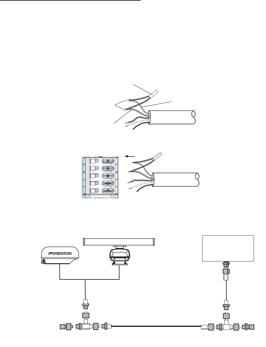
How to terminate of NMEA2000 connection
When connecting the radar sensor and an NMEA2000 equipment using the optional cable M12-
05BFFM (φ6) or CB-05BFFM (φ10), attach the terminator (supplied as installation materials) to the
NMEA connector in the radar sensor.
1. Twist the lead wire of the resistor assembly to the cable M12-05BFFM (φ6) or CB-05BFFM
(φ10), and solder them as below.
2. Connect wires to the NMEA connector consulting the label on the connector.
Note: This fabrication is not necessary when the external terminators are attached as below.
Resistor assembly
(120 OHM-1007#24-L150)
Twisting and
soldering
White
Blue
NMEA2000 cable
NMEA2000 connector
(in the sensor)
Backbone cable
External
terminator 1
External
terminator 2
NMEA2000
equipment
DRS4A/DRS6A/DRS12A
DRS2D/DRS4D
or
12
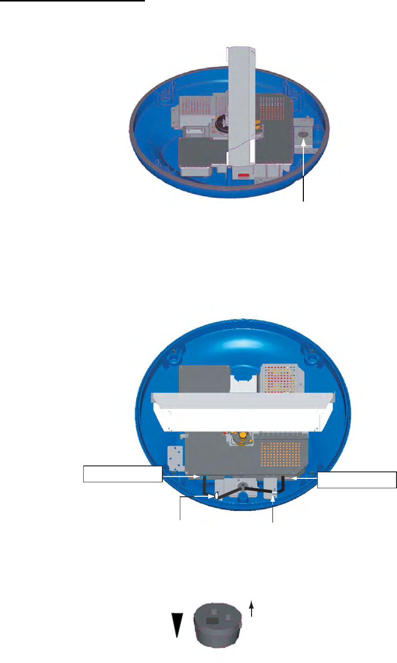
2.1 Wiring inside DRS2D/4D
Two-way cable connection
1. Unfasten three screws at the bottom of the mounting base to remove the fixing plate for the
gasket.
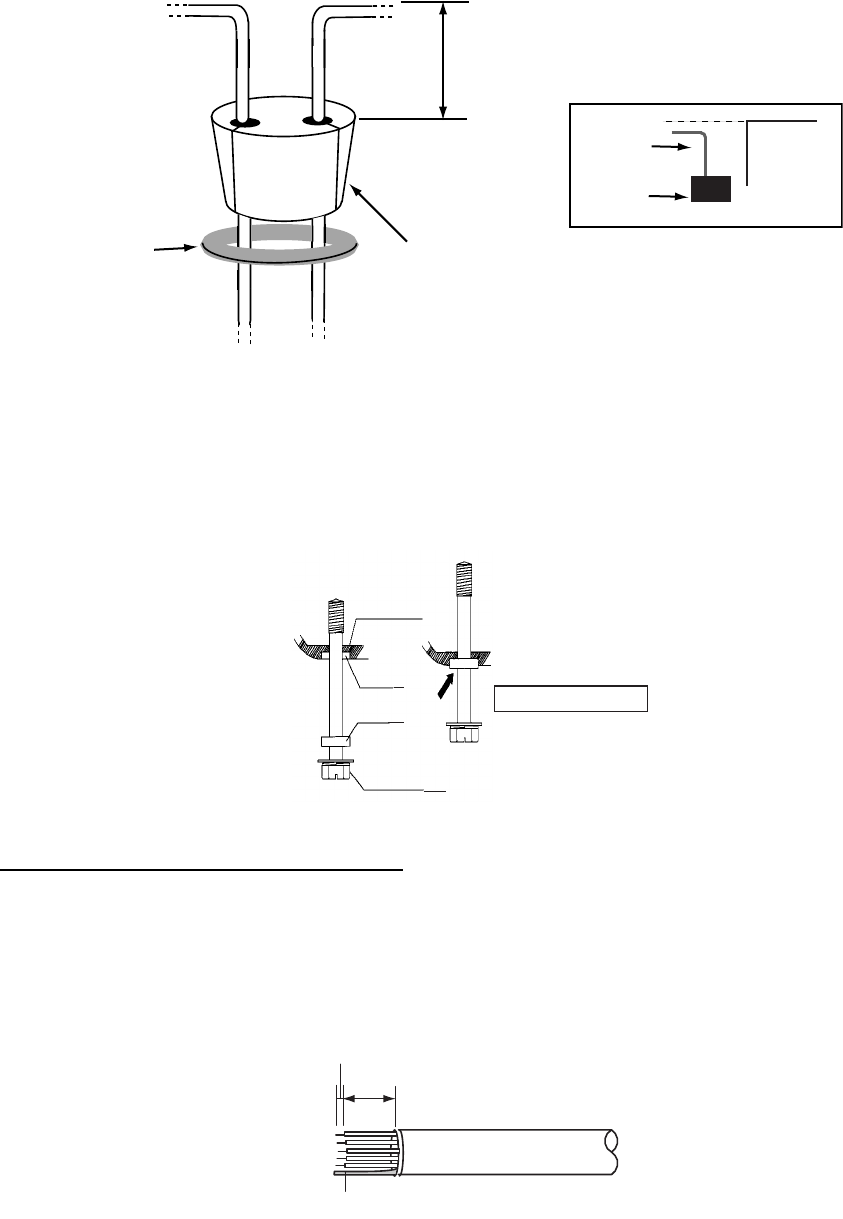
2. Remove the gasket, and pass the two-way cable MOD-ASW0001.
3. Fasten the shield of the cable (power) with the cable clamp in the radar sensor, and connect
the connector of cable (power) to the power terminal.
4. Connect the RJ-45 connector of the cable (LAN) to the LAN terminal in the radar sensor.
5. Push cables of the two-way cable into the slits of the gasket inside the radar sensor.
Note: The ends of the gasket are different. Larger end should be up.
Fixing plate
(for gasket)
Power terminal
Fix the shield cable
(power) with this clamp.
Fix the cable (LAN)
with this locking saddle.
LAN terminal
Up
Large
Small
13
6. Slide the gasket on cables so that the amount of cable above the gasket is lower than the RF
chassis.
Note: If the two-way cable touches the platform near the mounting base, wind vinyl tape around
the cable at the point where it is bent.
7. Confirm that the rubber gasket is properly positioned and that the triangle mark on the cover is
aligned with the triangle mark on the mounting base, then tighten the fixing screws for the
cover.
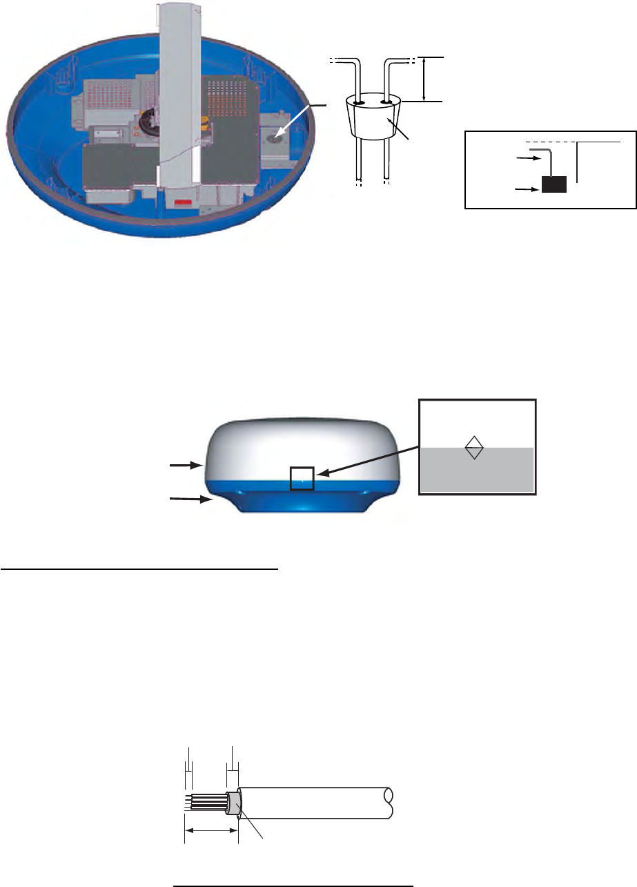
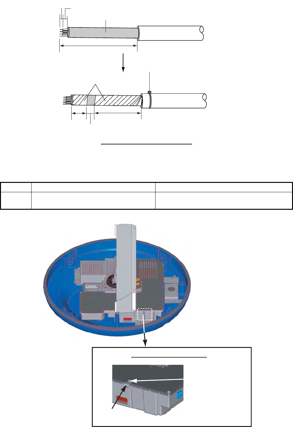
Connecting to NMEA2000 equipment
To connect NMEA2000 equipment to the sensor, wire an optional NMEA2000 cable, M12-05BFFM
(φ6) or CB-05BFFM (φ10), as shown below. Also, the gasket at the bottom of mounting base must
be replaced.
1. Do steps 1 to 4 on page 12.
2. Refer to the figure below, and fabricate the cable M12-05BFFM (φ6) or CB-05BFFM (φ10).
This height should
be lower than the RF
unit when installed to
the bottom of the sensor.
Gasket RF unit
Gasket
Cable
Triangle marks
Cover
Mounting
base
15 (Area fastened with the cable clamp)
5
M12-05BFFM cable
100
Fabrication of cable M12-05BFFM (φ6)
Shield
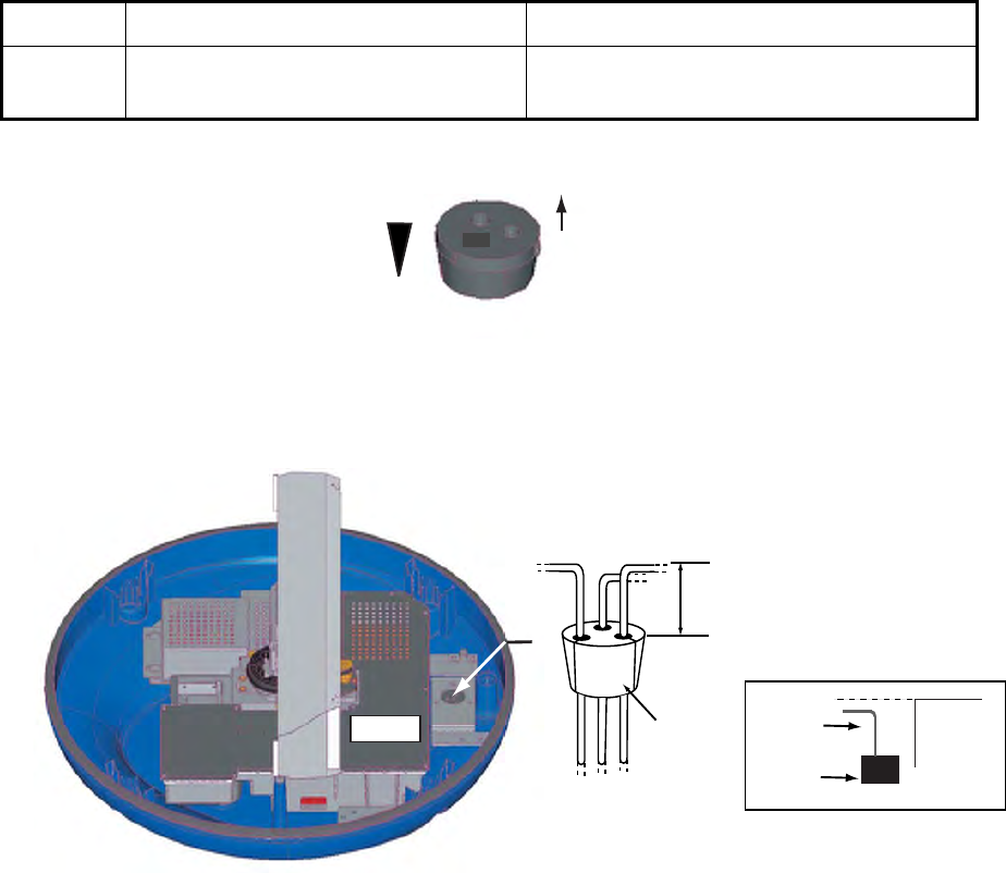
14
3. Insert wires of cable M12-05BFFM (φ6) or CB-05BFFM (φ10) to the NMEA connector inside the
radar sensor, consulting the label on the connector for location. As for shield, use the cable
clamp shown below.
Cable M12-05BFFM (φ6) CB-05BFFM (φ10)
Clamp Use the clamp pre-attached inside the radar
sensor.
Use the clamp supplied with the optional gasket
(Type: OP03-203, Code No.: 001-025-290)
15
5
CB-05BFFM cable
370
CB-05BFFM cable
20 65
15 (Area fastened with the cable clamp)
Wind vinyl tape.
(supplied)
Fabrication of CB-05BFFM cable
Fasten the cable tie (supplied) within
15 mm from the end of vinyl sheath.
Shield
Zoom up
Attach the cable clamp
using this screw for CB-
05BFFM cable. (Face
projecting part down.)
Cable clamp
Location of the cable clamp
15
4. Push LAN and POWER cables of the two-way cable and cable M12-05BFFM (φ6) or CB-
05BFFM (φ10) into the slits of the gasket inside the mounting base. Depending on the
NMEA2000 cable used, replace the gasket as shown below.
Note: The ends of the gasket are different. Larger end should be up)
5. Slide the gasket on cables so that the amount of cable above the gasket is lower than the RF
chassis.
Note: If the two-way cable touches the platform near the radar sensor base, wind vinyl tape
around the cable at the point where is bent.
6. Confirm that the rubber gasket is properly positioned and that the triangle mark on the cover is
aligned with the triangle mark on the mounting base, then tighten the fixing screws for the
cover.
Cable type M12-05BFFM (φ6) CB-05BFFM (φ10)
Gasket Use the gasket supplied in the plastic
bag inside the radar sensor.
Use the optional gasket. (Type: OP03-203,
Code No.: 001-025-290)
Up
Large
Small
This height should
be lower than the RF
unit when attaching to
the bottom of the sensor.
Gasket
RF unit
RF unit
Gasket
Cable
16
2.2 Wiring inside DRS4A/6A/12A/25A
Two-way cable connection
If you have no NMEA2000 equipment to connect, use the MOD-ASW0001 cable (standard sup-
ply).
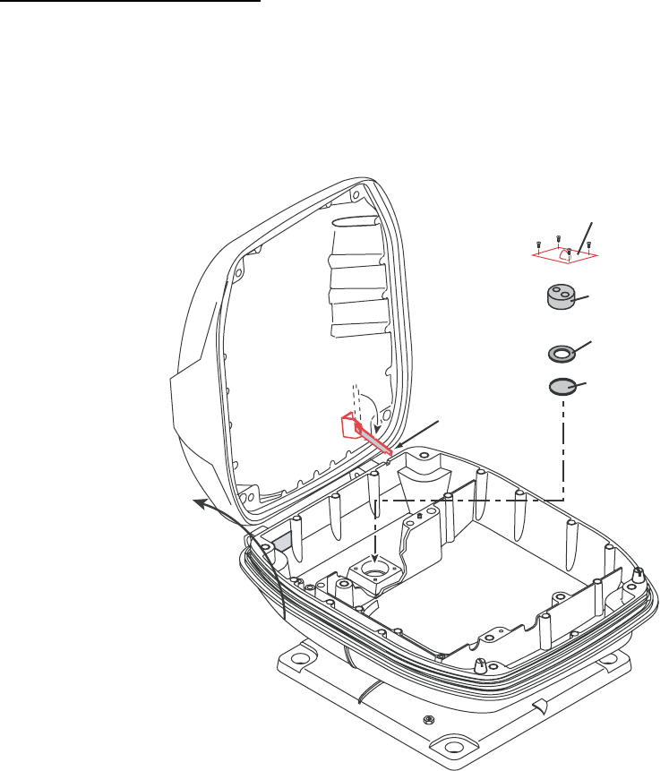
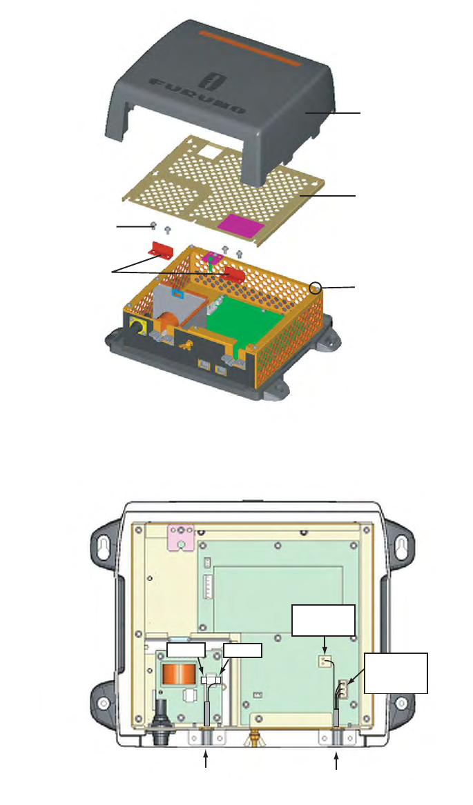
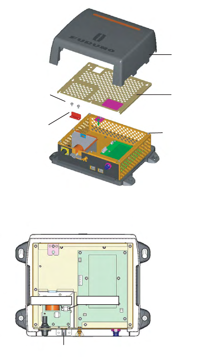
1. Open the radar sensor cover by loosening four bolts, and fix the stay for safety purpose.
2. Unfasten four bolts to detach the plate, gasket, washer and lid. Discard the lid at the bottom of
the hole for the gasket.
3. Pass the two-way cable MOD-ASW0001 (MOD-ASW0002 for DRS25A) through the bottom of
the chassis and washer.
4. Fasten the shield of the power cable of the two-way cable (part of the foil) with the cable
clamp in the radar sensor, and then connect the power cable to the power terminal as shown
on next page.
Gasket
Washe
r
Lid
Stay
Plate
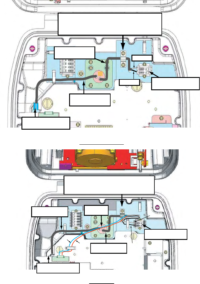
17
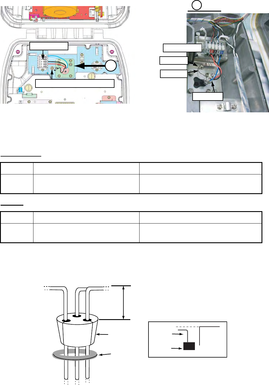
5. Attach the LAN cable of the two-way cable to the LAN terminal in the radar sensor.
DRS4A/6A/12A
DRS25A
6. Refer to the illustration shown below, and attach the gasket to the two-way cable, inserting the
cable into the slits on the gasket.
Fix the power cable at the foil part
with this cable clamp.
Power terminal
LAN terminal
Power cable
LAN cable
Black
White
RF unit
Fix the power cable at the copper
foil part with this cable clamp.
Power terminal
Gasket
LAN terminal
White
Black
LAN cable
Blue
Red Power cable
18
7. Slide the gasket on cables so that the amount of cable above the gasket is lower than the RF
chassis.
8. Push the gasket and washers into the hole at the bottom of the radar sensor, then fasten four
pan head screws to fix the plate to the sensor.
9. Release the stay and close the cover.
Note: When closing the cover, set the gaskets to grooves in the bottom chassis, then tighten bolts.
Connecting to NMEA2000 equipment
To connect NMEA2000 equipment to the sensor, use an optional NMEA2000 cable, M12-05BFFM
(φ6) or CB-05BFFM (φ10). Also, the gasket at the bottom of the antenna sensor must be replaced.
1. Do steps 1 to 5 on pages 16 and 17.
2. Fabricate the cable M12-05BFFM (φ6) or CB-05BFFM (φ10) as shown below.
3. Pass the cable through the bottom of the chassis.
4. Insert wires of the cable M12-05BFFM (φ6) or CB-05BFFM (φ10) to the NMEA connector inside
the radar sensor, consulting the label on the connector for location. As for drain wire, attach
This height should be lower than the
RF unit when installed to the bottom
of the sensor.
Gasket
Washers
RF unit
Gasket
Cable
BOTTOM
CHASSIS
GASKET
GROOVE
HEX BOLT
Torque : 9.8 ±0.1 N m
.
95
5
Drain wire
Cable M12-05BFFM
or CB-05BFFM
19
the crimp-on lug (pre-attached at the bottom of the chassis) to the drain wire, and fasten it with
the screw shown below.
5. Depending on the NMEA2000 used, replace the gasket as shown below.
DRS4A/6A/12A
DRS25A
6. Refer to the illustration shown on next page, and attach the gasket to the two-way cable
inserting the cable into the slits on the gasket.
7. Slide the gasket on cables so that the amount of cable above the gasket is lower than the RF
chassis.
8. Do steps 8 and 9 on page 18.
Cable type M12-05BFFM (φ6) CB-05BFFM (φ10)
Gasket Use the gasket supplied in the plastic
bag inside the radar sensor.
Use the optional gasket. (Type: OP03-205,
Code No.: 001-025-790)
Cable type M12-05BFFM (φ6) CB-05BFFM (φ10)
Gasket Use the gasket supplied in the plastic
bag inside the radar sensor.
Use the optional gasket. (Type: OP03-206,
Code No.: 001-035-290)
NMEA connector
Fasten the drain wire with this screw.
A
Aview
NMEA cable
NMEA connector
Drain wire
Crimp-on lug
RF unit
This height should be lower than the
RF unit when installed to the bottom
of the sensor.
Washer
Gasket RF uni
t
Gasket
Cable
20
2.3 Wiring of Power Supply Unit PSU-013 (for
DRS25A)
1. Detach the body cover by hand.
2. Loosen six pan head screws (M3x8) and slide the shield cover upward to remove it.
3. Unfasten four pan head screws (M14x10) to remove two cable clamps.
4. Connect the cable VL3P-VV-S2X2C-AA50 and MOD-ASW0002 cables (supplied) to appropri-
ate connectors in the power supply unit as shown below.
5. Remove two cable clamps, shield cover and body cover in that order.
6. Connect other cables.
Body cover
Shield cover
Pan head screws
(M3x8, 6 pcs.)
Pan head screws
(M4x10, 4 pcs.)
Cable clamps
VL3P-VV-S2X2C-AA50 cable MOD-ASW0002 cable
(Power)
White Black 1: White
2: Black
3: Blue
1: Red
2: N. C.
21
2.4 Wiring inside Power Supply Unit PSU-012
(Option)
1. Detach the body cover by hand.
2. Loosen six pan head screws (M3x8) and slide the shield cover upward to remove it.
3. Unfasten two pan head screws (M4x12) to remove the cable clamp.
4. Connect the cable VL3P-VV-S2X2C-AA050 (supplied) to the power connector in the PSU-
012.
5. Remount the cable clamp, shield cover and body cover in that order.
6. Connect other cables.
Body cover
Shield cover
Pan head screw
(M3x8, 6 pcs.)
Pan head screw
(M4x12, 2 pcs.)
Cable clamp
For white wire For black wire
Put the cable VL3P-VV-S2X2C-AA050 here at the shield part.
%1&'01
6;2'
%2
⇛ޓޓ࿑
176.+0'
ฬޓޓ⒓
0#/'
ᢙ㊂
36;
↪ㅜ㧛⠨
4'/#4-5
⇟ภ
01
ဳฬ㧛ⷙᩰ
&'5%4+26+105
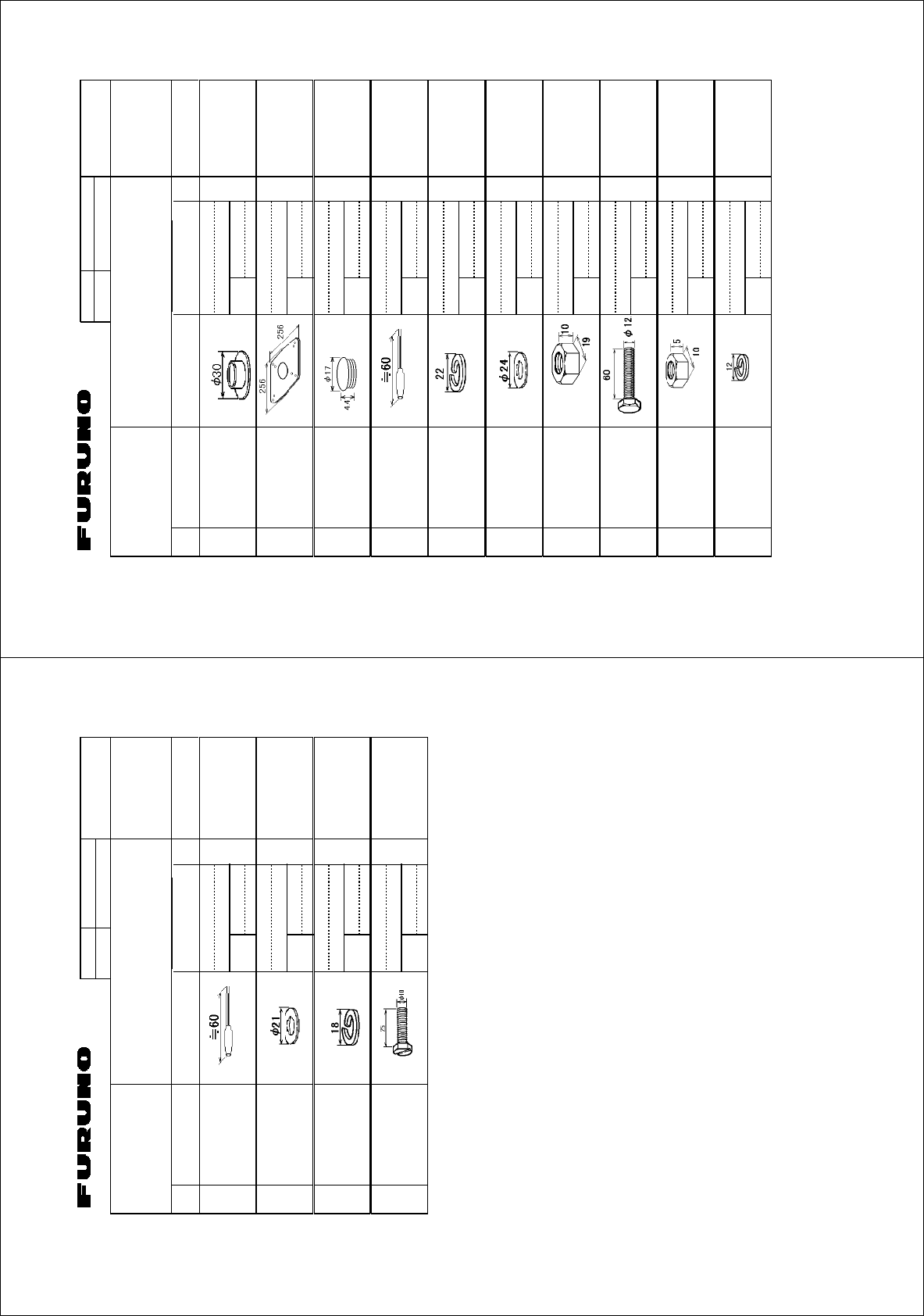
+056#..#6+10/#6'4+#.5
Ꮏ᧚ᢱ
);:
45$
㩆㨺㩣㩦㨹㩆㨶㨺
5'#.9#5*'4 41*5
%1&'01
㒐ⲁࠧࡓ
%14415+102411(
47$$'4/#6
41*5
%1&'01
㩁㨶㨹㩖㩩
-01$%#2
%1&'01
㩍㨼㩄㨽⚵ຠ
4'5+5614#55'/$.; 1*/.
%1&'01
㩔㩨㩒ᐳ㊄
524+0)9#5*'4 /575
%1&'01
㩚㩀㩨㩁㩙㩣ᐔᐳ㊄
(.#69#5*'4 /575
%1&'01
ⷺ㩏㨹㩎㩆㨷
*':#)10#.076 /575
%1&'01
ⷺ㩘㩨㩣㩎㧔ో㩒㩆㩨㧕
*':#)10*'#&5%4'9 /:575
%1&'01
ⷺ㩏㨹㩎㩆㨷
*':#)10#.076 /575
%1&'01
㩔㩨㩒ᐳ㊄
524+0)9#5*'4 /575
%1&'01
㧔⇛࿑ߩኸᴺߪޔෳ⠨୯ߢߔޕޓ&+/'05+105+0&4#9+0)(144'('4'0%'10.;㧕
㧲㨁㧾㨁㧺㧻ޓ㧱㧸㧱㧯㨀㧾㧵㧯ޓ㧯㧻ޓ㧚
㧘
㧸㨀㧰
);:
ဳᑼ㩄㨺㩎㩨⇟ภ߇㧞Ბߩ႐วޔਅᲑࠃࠅᲑߦઍࠊࠆㆊᷰᦼຠߢࠅޔߤߜࠄ߆߇ߞߡ߹ߔޕޓߥ߅ޔຠ⾰ߪᄌࠊࠅ߹ߖࠎޕ
6916;2'5#0&%1&'5/#;$'.+56'&(14#0+6'/6*'.19'4241&7%6/#;$'5*+22'&+02.#%'1(6*'722'4241&7%6
37#.+6;+56*'5#/'
A-2
%1&'01
6;2'
%2
⇛ޓޓ࿑
176.+0'
ฬޓޓ⒓
0#/'
ᢙ㊂
36;
↪ㅜ㧛⠨
4'/#4-5
⇟ภ
01
ဳฬ㧛ⷙᩰ
&'5%4+26+105
+056#..#6+10/#6'4+#.5
Ꮏ᧚ᢱ
*#:
㩍㨼㩄㨽⚵ຠ
4'5+5614#55'/$.; 1*/.
%1&'
01
㩚㩀㩨㩁ᐔᐳ㊄
(.#69#5*'4 /575
%1&'
01
/575
㩔㩨㩒ᐳ㊄
524+0)9#5*'4 /575ޓ
%1&'
01
/575
ⷺ㩇㩢㩦㩢㩘㩨㩣㩎
*':$1.65.166'&
*'#&
/:575
%1&'
01
㧔⇛࿑ߩኸᴺߪޔෳ⠨୯ߢߔޕޓ&+/'05+105+0&4#9+0)(144'('4'0%'10.;㧕
㧲㨁㧾㨁㧺㧻ޓ㧱㧸㧱㧯㨀㧾㧵㧯ޓ㧯㧻ޓ㧚
㧘
㧸㨀㧰
*#:
ဳᑼ㩄㨺㩎㩨⇟ภ߇㧞Ბߩ႐วޔਅᲑࠃࠅᲑߦઍࠊࠆㆊᷰᦼຠߢࠅޔߤߜࠄ߆߇ߞߡ߹ߔޕޓߥ߅ޔຠ⾰ߪᄌࠊࠅ߹ߖ
ࠎޕ
6916;2'5#0&%1&'5/#;$'.+56'&(14#0+6'/6*'.19'4241&7%6/#;$'5*+22'&+02.#%'1(6*'722'4
241&7%637#.+6;+56*'5#/'
A-1
%1&'01
6;2'
⇛ޓޓ࿑
176.+0'
ฬޓޓ⒓
0#/'
ᢙ㊂
36;
↪ㅜ㧛⠨
4'/#4-5
⇟ภ
01
ဳฬ㧛ⷙᩰ
&'5%4+26+105
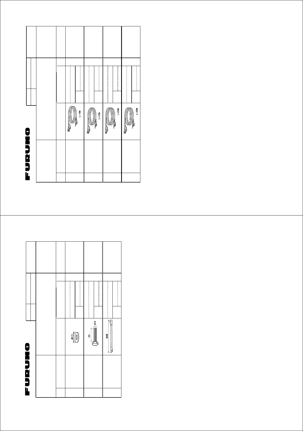
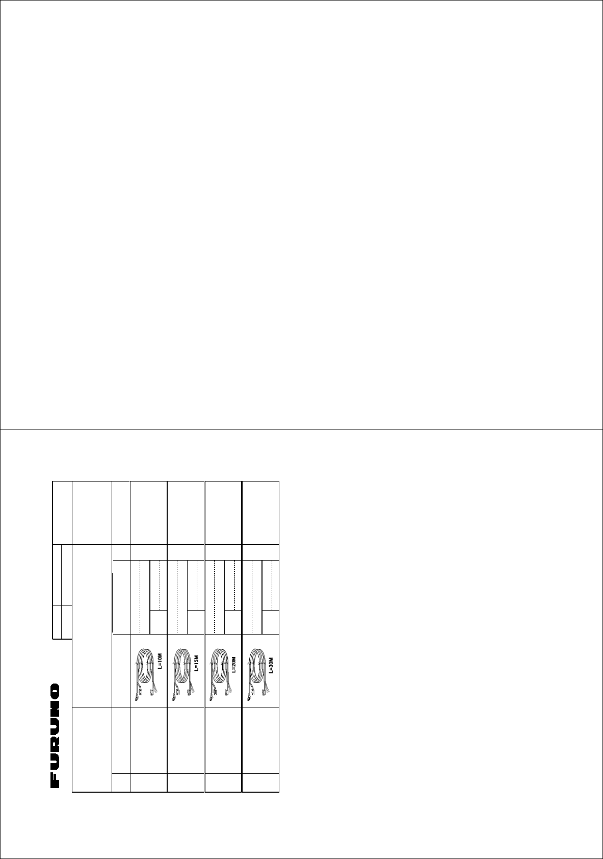
+056#..#6+10/#6'4+#.5
Ꮏ᧚ᢱ
*#:
4#-'0514
&45&&&45###
㩃㨺㩖㩨㩣⚵ຠ
%#$.'#55; /1;
ㆬᛯޓ61$'
5'.'%6'&
%1&'01
㩃㨺㩖㩨㩣⚵ຠ
%#$.'#55; /1;
ㆬᛯޓ61$'
5'.'%6'&
%1&'01
㩃㨺㩖㩨㩣⚵ຠ
%#$.'#55; /1;
ㆬᛯޓ61$'
5'.'%6'&
%1&'01
㩃㨺㩖㩨㩣⚵ຠ
%#$.'#55; /1;
ㆬᛯޓ61$'
5'.'%6'&
%1&'01
㧔⇛࿑ߩኸᴺߪޔෳ⠨୯ߢߔޕޓ&+/'05+105+0&4#9+0)(144'('4'0%'10.;㧕
㧲㨁㧾㨁㧺㧻ޓ㧱㧸㧱㧯㨀㧾㧵㧯ޓ㧯㧻ޓ㧚
㧘
㧸㨀㧰
*#:
ᮡḰߪ㨙ߢࠆ߇ᔅⷐߦࠃࠅㆬᛯน
56#0&.'0)6*+5/16*'4.'0)6*5#4'#.51#8#+.#$.'
ဳᑼ㩄㨺㩎㩨⇟ภ߇㧞Ბߩ႐วޔਅᲑࠃࠅᲑߦઍࠊࠆㆊᷰᦼຠߢࠅޔߤߜࠄ߆߇ߞߡ߹ߔޕޓߥ߅ޔຠ⾰ߪᄌࠊࠅ߹ߖࠎޕ
6916;2'5#0&%1&'5/#;$'.+56'&(14#0+6'/6*'.19'4241&7%6/#;$'5*+22'&+02.#%'1(6*'722'4241&7%6
37#.+6;+56*'5#/'
A-4
%1&'01
6;2'
%2
⇛ޓޓ࿑
176.+0'
ฬޓޓ⒓
0#/'
ᢙ㊂
36;
↪ㅜ㧛⠨
4'/#4-5
⇟ภ
01
ဳฬ㧛ⷙᩰ
&'5%4+26+105
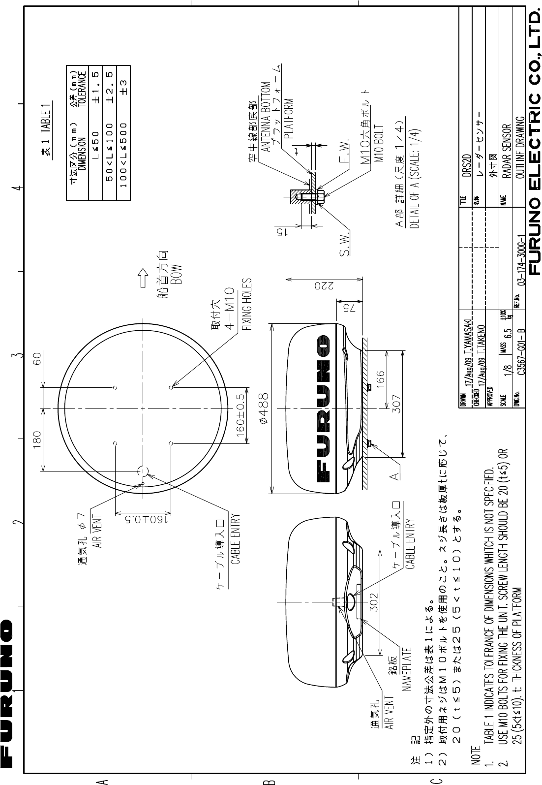
+056#..#6+10/#6'4+#.5
Ꮏ᧚ᢱ
);:
45$
㩚㩀㩨㩁ᐔᐳ㊄
(.#69#5*'4 /575
%1&'01
ⷺ㩘㩨㩣㩎
*':#)10#.*'#&$1.6 /:575
%1&'01
㩃㨺㩖㩨㩣⚵ຠ
%#$.'#55; 49
%1&'01
49
㧔⇛࿑ߩኸᴺߪޔෳ⠨୯ߢߔޕޓ&+/'05+105+0&4#9+0)(144'('4'0%'10.;㧕
㧲㨁㧾㨁㧺㧻ޓ㧱㧸㧱㧯㨀㧾㧵㧯ޓ㧯㧻ޓ㧚
㧘
㧸㨀㧰
);:
ဳᑼ㩄㨺㩎㩨⇟ภ߇㧞Ბߩ႐วޔਅᲑࠃࠅᲑߦઍࠊࠆㆊᷰᦼຠߢࠅޔߤߜࠄ߆߇ߞߡ߹ߔޕޓߥ߅ޔຠ⾰ߪᄌࠊࠅ߹ߖࠎޕ
6916;2'5#0&%1&'5/#;$'.+56'&(14#0+6'/6*'.19'4241&7%6/#;$'5*+22'&+02.#%'1(6*'722'4241&7%6
37#.+6;+56*'5#/'
A-3
%1&'01
6;2'
⇛ޓޓ࿑
176.+0'
ฬޓޓ⒓
0#/'
ᢙ㊂
36;
↪ㅜ㧛⠨
4'/#4-5
⇟ภ
01
ဳฬ㧛ⷙᩰ
&'5%4+26+105
+056#..#6+10/#6'4+#.5
Ꮏ᧚ᢱ
*%:
4#-'0514
&45#
㩃㨺㩖㩨㩣⚵ຠ
%#$.'#55; /1;
ㆬᛯޓ61$'
5'.'%6
%1&'
01
㩃㨺㩖㩨㩣⚵ຠ
%#$.'#55; /1;
ㆬᛯޓ61$'
5'.'%6
%1&'
01
㩃㨺㩖㩨㩣⚵ຠ
%#$.'#55; /1;
ㆬᛯޓ61$'
5'.'%6
%1&'
01
㩃@㩖㩨㩣⚵ຠ
%#$.'#55; /1;
ㆬᛯޓ61$'
5'.'%6
%1&'
01
㧔⇛࿑ߩኸᴺߪޔෳ⠨୯ߢߔޕޓ&+/'05+105+0&4#9+0)(144'('4'0%'10.;㧕
㧲㨁㧾㨁㧺㧻ޓ㧱㧸㧱㧯㨀㧾㧵㧯ޓ㧯㧻ޓ㧚
㧘
㧸㨀㧰
*%:
ဳᑼ㩄㨺㩎㩨⇟ภ߇㧞Ბߩ႐วޔਅᲑࠃࠅᲑߦઍࠊࠆㆊᷰᦼຠߢࠅޔߤߜࠄ߆߇ߞߡ߹ߔޕޓߥ߅ޔຠ⾰ߪᄌࠊࠅ߹ߖ
ࠎޕ
6916;2'5#0&%1&'5/#;$'.+56'&(14#0+6'/6*'.19'4241&7%6/#;$'5*+22'&+02.#%'1(6*'722'4
241&7%637#.+6;+56*'5#/'
A-5
21/Aug/09 R.Esumi
D-1
22/Mar/08 R.Esumi
D-2
Jan.18'08 R.Esumi
D-3
2/Apr/08 R.Esumi
D-4
Oct.15'07 R.Esumi
D-5
243
A
1
B
C
DRAWN
CHECKED
APPROVED
DWG.No.
TITLE
NAME
名称
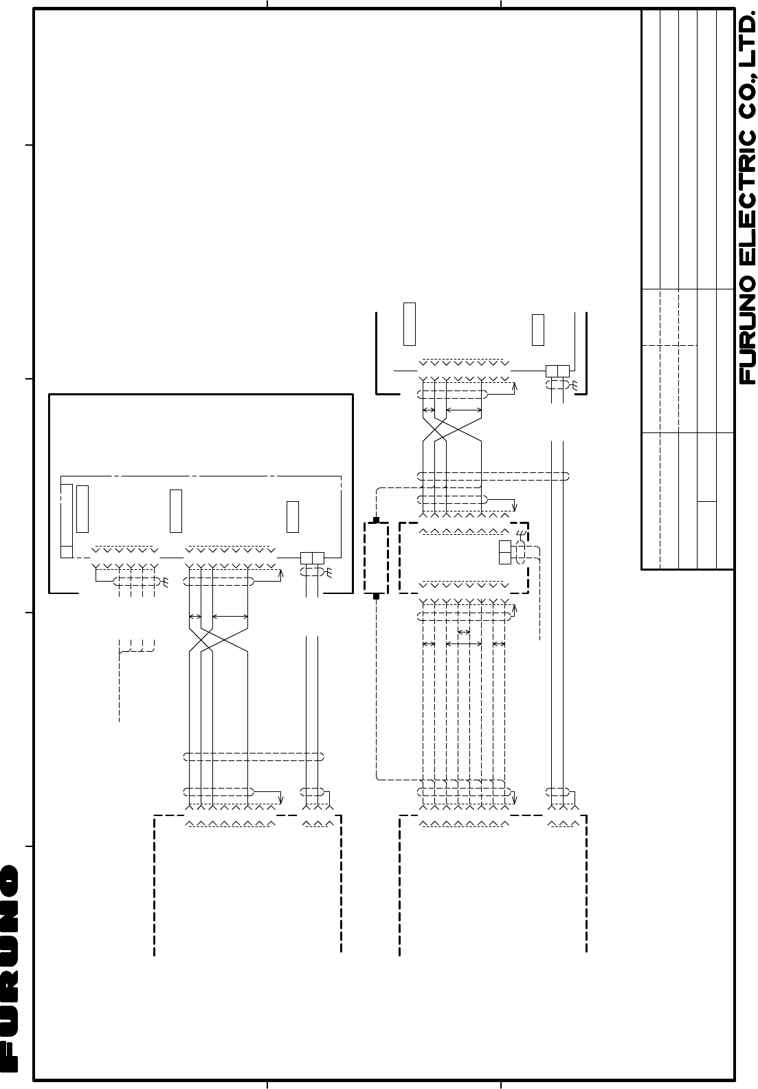
INTERCONNECTION DIAGRAM
相互結線図
REF.No.
SCALE MASS kg
レーダーセンサー
RADAR SENSOR
T.YAMASAKI
DRS2D/4D
T.TAKENO
NOTE
1. SHIPYARD SUPPLY.
2. OPTION.
注記
1)造船所手配。
2)オプション。
3)コネクタは工場にて取付済み。
3. CONNECTOR PLUG FITTED AT FACTORY.
Jan. 23 '08
Jan. 23 '08
C3567-C01- B 03-174-6001-1
1
2
4
5
6
3
SHIELD
NC
NET-S
NET-L
NET-H
NET-C
FMC1.5/6ST
B1
アカ
クロ
RED
BLK
シロ
アオ
WHT
BLU
RTR-090/091
1
2
4
5
6
3
7
8
NC
NC
E_TD-P
NC
E_TD-N
E_RD-P
NC
E_RD-N
1
2
P
P
GP-330B
SC-30
φ7
RADAR SENSOR
DRS2D/4D
レーダー
センサー
または
OR
48V-H
NMEA2000
POWER
J603
J301
J207
WS-200 etc.
48V-C
NETWORK
航法装置またはセンサー
NAV.EQUIPMENT OR SENSOR
CB-05BFFM,1/2/6m
*2
M12-05BFFM,1/2/6m
クロ BLK
シロ WHT
RJ45
*3
P
P
PP
1
2
4
5
6
3
7
8
NC
NC
E_TD-P
NC
E_TD-N
E_RD-P
NC
E_RD-N
*3
1
2
4
5
6
3
7
8
RJ45
*3
1
2
4
5
6
3
7
8
RJ45 J207 NETWORK
1
2
φ7
クロ BLK
シロ WHT 48V-H
POWER
J301
48V-C
1
2
(+)
(-)
J3
VVRx2C *1
HUB-101
ETHERNET HUB
*2
JUNCTION BOX
または OR DRS2D/4D
10/15/20/30m
MOD-ASW0001,φ6
TL-CAT-012 *2
P
P
RJ45RJ45
1
2
4
5
6
3
7
8
NC
NC
E_TD-P
NC
E_TD-N
E_RD-P
NC
E_RD-N
1
2
3
+48V
GND
RJ45
MJ-A3SPF
SHIELD
*3
*3
MOD-ASW0001,10/15/20/30m,φ6
1
2
4
5
6
3
7
8
NC
NC
E_TD-P
NC
E_TD-N
E_RD-P
NC
E_RD-N
1
2
3
+48V
GND
MJ-A3SPF
SHIELD
*3
MFD8/12
MFDBB(MPU-001)
MULTI-FUNCTION DISPLAY
MFD8/12
MFDBB(MPU-001)
マルチファンクションディスプレイ
MOD-WPAS0001,3m
MOD-WPAS0001,3m
*2
*2
RJ45
*3
12-24VDC
MOD-Z072,2/5/10m,φ6(CROSS) OR RJ45
*3
Jan.23'08 R.Esumi
S-1
243
A
1
B
C
DRAWN
CHECKED
APPROVED
DWG.No.
TITLE
NAME
名称
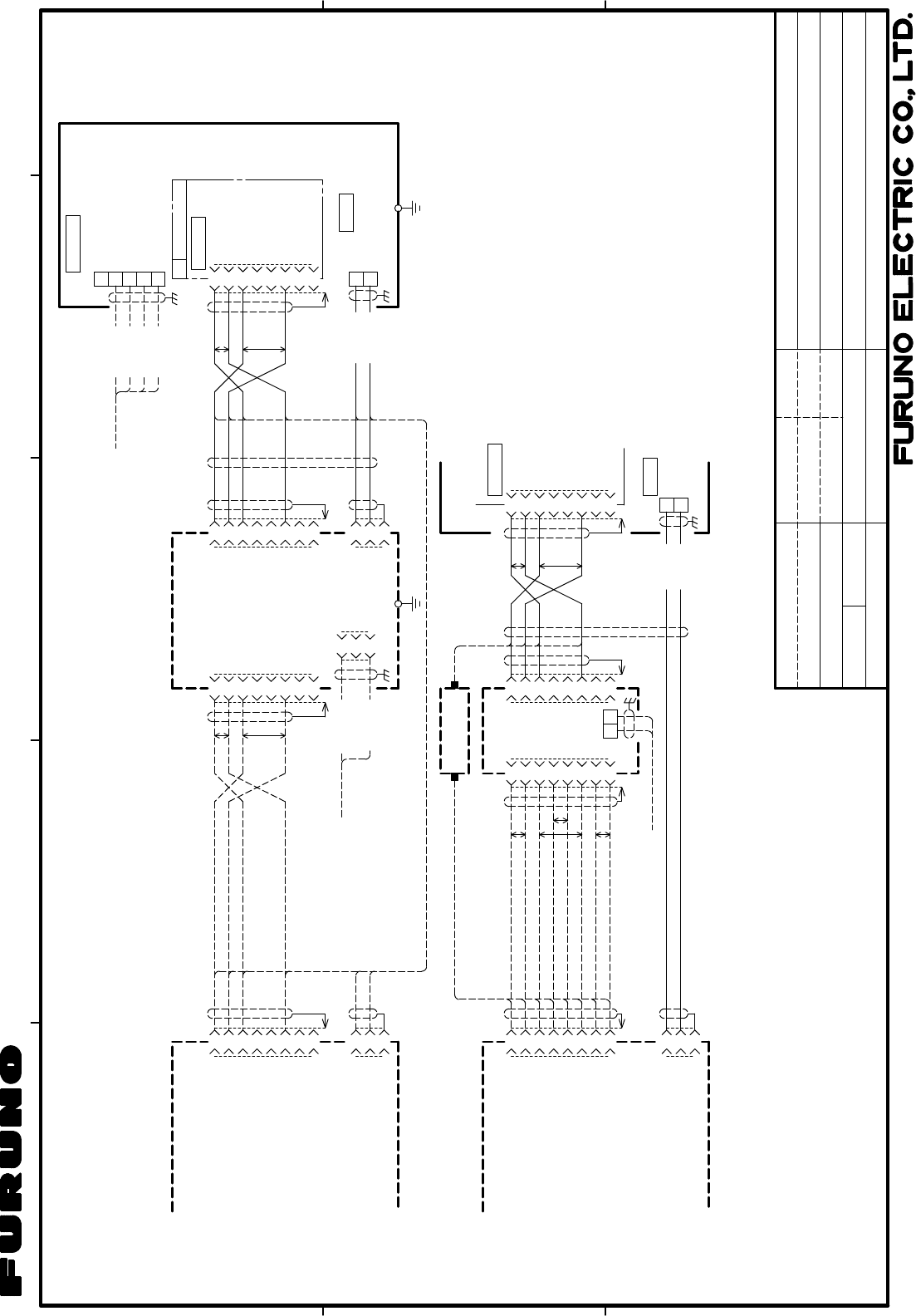
INTERCONNECTION DIAGRAM
相互結線図
REF.No.
SCALE MASS kg
レーダーセンサー
RADAR SENSOR
T.YAMASAKI
T.TAKENO
DRS4A/6A
NOTE
1. SHIPYARD SUPPLY.
2. OPTION.
注記
1)造船所手配。
2)オプション。
3)コネクタは工場にて取付済み。
3. CONNECTOR PLUG FITTED AT FACTORY.
03-174-6003-3
P
P
PP
1
2
4
5
6
3
7
8
NC
NC
E_TD-P
NC
E_TD-N
E_RD-P
NC
E_RD-N
*3
1
2
4
5
6
3
7
8
RJ45
*3
1
2
4
5
6
3
7
8
P
P
RJ45 NETWORK
1
2
φ7 シロ WHT
クロ BLK
48V-H
POWER
48V-C
1
2
(+)
(-)
J3
12-24VDC VVRx2C *1
HUB-101
ETHERNET HUB
*2
または OR
1
2
4
5
6
3
7
8
NC
NC
E_TD-P
NC
E_TD-N
E_RD-P
NC
E_RD-N
P
P
B2
アカ
クロ
RED
BLK
シロ
アオ
WHT
BLU
1
2
4
5
3
NET-S
NET-L
NET-H
NET-C
SHIELD
RTR-092/093
TB102
NMEA2000
航法装置またはセンサー
NAV.EQUIPMENT OR SENSOR
GP-330B
SC-30
CB-05BFFM,1/2/6m
RJ45
*3
空中線部
ANTENNA UNIT
RSB-118
WS-200 etc.
NETWORK
RW-4747,0.3m
M12-05BFFM,1/2/6m
*2
1
2
4
5
6
3
7
8
NC
NC
E_TD-P
NC
E_TD-N
E_RD-P
NC
E_RD-N
*3
RJ45
P
P
J2
クロ BLK
シロ WHT
PSU-012
POWER SUPPLY UNIT
1
2
4
5
6
3
7
8
RJ45
*3 MOD-ASW0001,
10/15/20/30m,φ6
*2
VL3P-VVS2x2C,5m
12-24VDC
*1PSU-012を使わない場合
WHEN PSU-012 IS NOT USED
パワーサプライユニット
MOD-Z072,5m,φ6
(2/10m *2)
JUNCTION BOX
TL-CAT-012 *2
RJ45RJ45
10/15/20/30m
MOD-ASW0001,φ6
1
2
4
5
6
3
7
8
NC
NC
E_TD-P
NC
E_TD-N
E_RD-P
NC
E_RD-N
1
2
3
+48V
GND
MJ-A3SPF
SHIELD
*3
MFD8/12
MFDBB(MPU-001)
1
2
4
5
6
3
7
8
NC
NC
E_TD-P
NC
E_TD-N
E_RD-P
NC
E_RD-N
RJ45
*3
MULTI-FUNCTION DISPLAY
MFD8/12
MFDBB(MPU-001)
マルチファンクションディスプレイ
1
2
3
+48V
GND
SHIELD
MJ-A3SPF
*3
MOD-WPAS0001,3m
MOD-WPAS0001,3m
*2
*2
MOD-Z072,2/5/10m,φ6(CROSS) OR RJ45
*3
RJ45
*3
PSU-012
RSB-118 OR
IV-2sq.
1
2
48V-H
48V-C
クロ BLK
シロ WHT
TB101
φ7 POWER
1
2
3
48V-H
48V-L
SHIELD
MJ-A3SPF
*3
C3569-C01- C
J11
1/Apr/08
1/Apr/08
1(+)
J1
(-)
2
3
2/Apr/08 R.Esumi
S-2
243
A
1
B
C
1
2
4
5
6
3
7
8
NC
NC
E_TD-P
NC
E_TD-N
E_RD-P
NC
E_RD-N
RJ45 J2
*3
シロ WHT
クロ BLK
1
2
4
5
6
3
7
8
NC
NC
E_TD-P
NC
E_TD-N
E_RD-P
NC
E_RD-N
RJ45J3
PSU-012
POWER SUPPLY UNIT
パワーサプライユニット
1
2
4
5
6
3
7
8
NC
NC
E_TD-P
NC
E_TD-N
E_RD-P
NC
E_RD-N
B2
1
2
4
5
3
NET-S
NET-L
NET-H
NET-C
SHIELD
NMEA2000
TB102
RJ45
RTR-094
1
2
48V-H
48V-Cクロ BLK
シロ WHT
TB101
P
P
POWER
J207MOD-ASW0001,10/15/20/30m,φ6 NETWORK
RW-4747,0.3m
φ7
*1
IV-2sq.
空中線部
ANTENNA UNIT
RSB-118
1
2
3
48V-H
48V-L
SHIELD
MJ-A3SPF
*3
J11J1
1
2
3
(+)
(-)
*3 *3
VL3P-VVS2x2C,5m
P
P
PP
*2
P
P
PP
1
2
4
5
6
3
7
8
RJ45
*3
1
2
4
5
6
3
7
8
HUB-101
ETHERNET HUB
RJ45
*3
1
2
4
5
6
3
7
8
NC
NC
E_TD-P
NC
E_TD-N
E_RD-P
NC
E_RD-N
RJ45
*3
MFD8/12
MFDBB(MPU-001)
または OR
JUNCTION BOX
TL-CAT-012
MOD-WPAS0001,3m
MOD-Z072,2/5/10m,φ6(CROSS) OR
*2
MOD-WPAS0001,3m
1
2
(+)
(-)
J3
MOD-Z072,2/5/10m,φ6
1
2
4
5
6
3
7
8
NC
NC
E_TD-P
NC
E_TD-N
E_RD-P
NC
E_RD-N
RJ45
*3
MULTI-FUNCTION DISPLAY
MFDBB(MPU-001)
MFD8/12
マルチファンクションディスプレイ
1
2
3SHIELD
MJ-A3SPF
*3
MFDBB(MPU-001) ONLY
+48V
GND
12-24VDC
PSU-012を使わない場合(MFDBBのみ)
WHEN PSU-012 IS NOT USED (FOR MFDBB ONLY)
*2
1
2
4
5
6
3
7
8
NC
NC
E_TD-P
NC
E_TD-N
E_RD-P
NC
E_RD-N
*3
P
P
PP
RJ45 J2
PSU-012
*2
MOD-Z072,2/5/10m,φ6
12-24VDC VVRx2C *1
DRAWN
CHECKED
APPROVED
DWG.No.
TITLE
NAME
名称
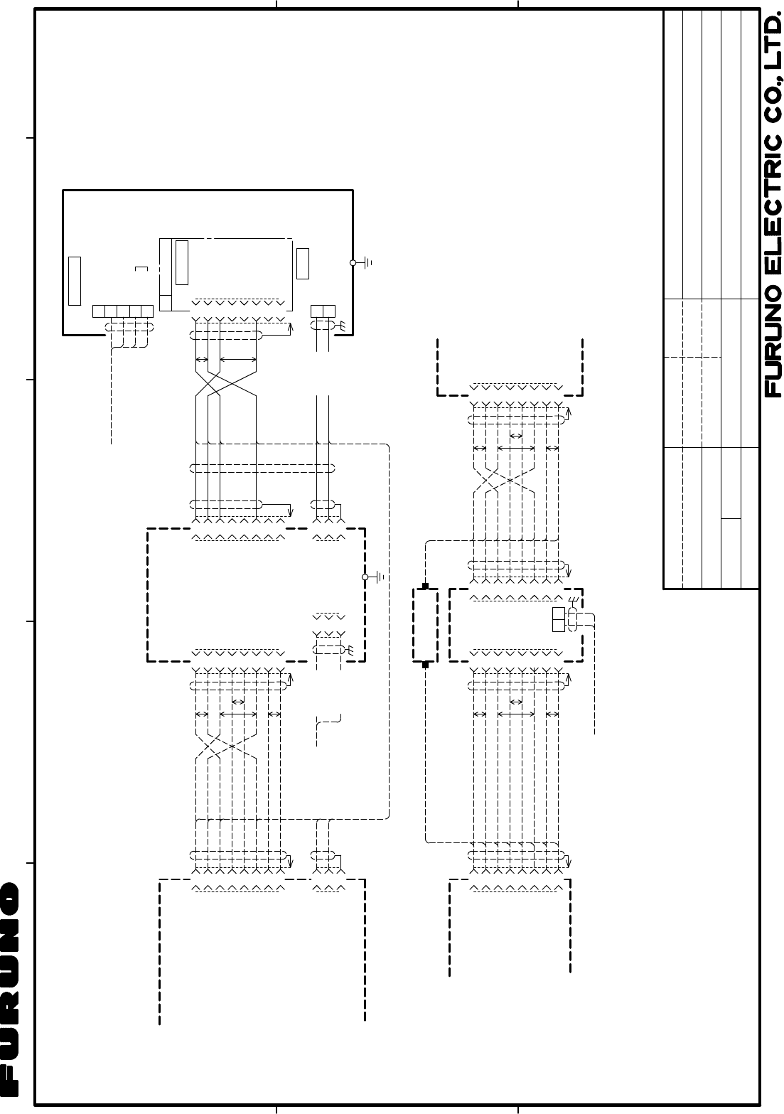
INTERCONNECTION DIAGRAM
相互結線図
REF.No.
SCALE MASS kg
レーダーセンサー
RADAR SENSOR
T.YAMASAKI
T.TAKENO
DRS12A
03-174-6003-3
28/May/08
28/May/08
C3571-C01- D
航法装置またはセンサー
NAV. EQUIPMENT OR SENSOR
GP-330B
SC-30
WS-200 etc.
NOTE
注記
*4
*1)造船所手配。
*2)オプション。
*3)コネクタは工場にて取付済み。
*4)ターミネータを接続する。
*1: SHIPYARD SUPPLY.
*2: OPTION.
*3: CONNECTOR PLUG FITTED AT FACTORY.
*4: ATTACH A TERMINATOR.
12/Jun/08 R.Esumi
S-3
243
A
1
B
C
1
2
4
5
6
3
7
8
NC
NC
E_TD-P
E_TD-N
E_RD-P
E_RD-N
RJ45J3
1
2
4
5
6
3
7
8
NC
NC
E_TD-P
NC
E_TD-N
E_RD-P
NC
E_RD-N
B2
アカ
クロ
RED
BLK
シロ
アオ
WHT
BLU
1
2
4
5
3
NET-S
NET-L
NET-H
NET-C
SHIELD
NMEA2000
TB102
RJ45
P
P
GP-330B
SC-30
WS-200 etc.
J207 NETWORK
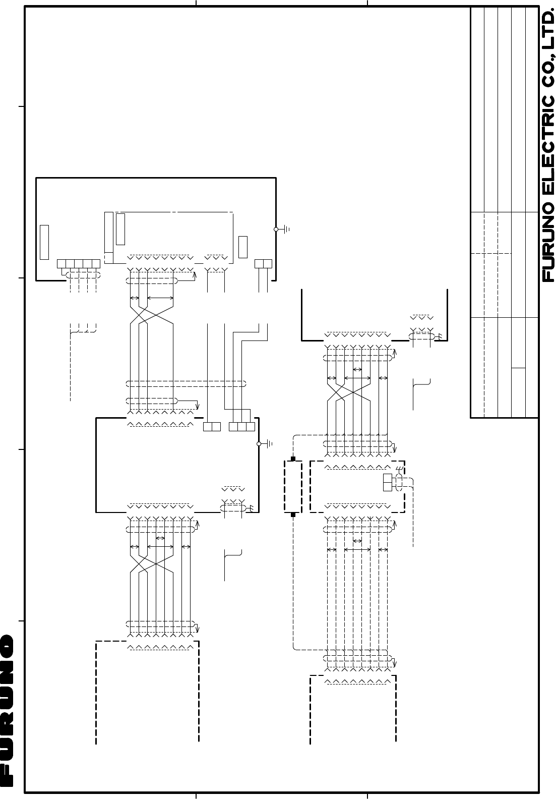
RTR-095
MOD-ASW0002,10/15/20/30m,φ6
航法装置またはセンサー
NAV.EQUIPMENT OR SENSOR
CB-05BFFM,1/2/6m
M12-05BFFM,1/2/6m
*2
空中線部
ANTENNA UNIT
RSB-118
1
2
(+)
J1
シロ WHT
(-)3クロ BLK
1
2
4
5
6
3
7
8
NC
NC
E_TD-P
E_TD-N
E_RD-P
E_RD-N
RJ45 J2
*3
P
P
PP
VL3P-VVS2x2C,5m
MOD-Z072,5m,φ6
(2/10m *2)
12/24VDC
POWER SUPPLY UNIT
パワーサプライユニット
PSU-013
MULTI-FUNCTION DISPLAY
マルチファンクションディスプレイ
1
2
4
5
6
3
7
8
NC
NC
E_TD-P
E_TD-N
E_RD-P
E_RD-N
RJ45
*3
MFDBB(MPU-001)
MFD8/12
DRAWN
CHECKED
APPROVED
DWG.No.
TITLE
NAME
名称
INTERCONNECTION DIAGRAM
相互結線図
REF.No.
SCALE MASS kg
レーダーセンサー
RADAR SENSOR
T.YAMASAKI
T.TAKENO
DRS25A
C3573-C01- A 03-174-6003-3
SW-P
SW-N
SW-P
SW-N
SW-P
SW-N
1
J5
TXHV アカ RED
2
NOTE
1. SHIPYARD SUPPLY.
2. OPTION.
注記
1)造船所手配。
2)オプション。
3)コネクタは工場にて取付済み。
3. CONNECTOR PLUG FITTED AT FACTORY.
RW-4747,0.3m
1
2
3
TXHV
NC
J305
GNDアオ BLU
+48V
GND
1
2
J4
3GND
*1
IV-2sq.
1
2
48V-H
48V-Cクロ BLK
シロ WHT TB101
POWER
1
2
4
5
6
3
7
8
NC
NC
E_TD-P
E_TD-N
E_RD-P
E_RD-N
*3
P
P
PP
RJ45
P
P
PP
1
2
4
5
6
3
7
8
RJ45
*3
1
2
4
5
6
3
7
8
J2
1
2
(+)
(-)
J3
12-24VDC VVRx2C *1 1 (+)
J1
シロ WHT
VL3P-VVS2x2C,5m
12/24VDC
(-)クロ BLK
2
3
HUB-101
ETHERNET HUB
*2
JUNCTION BOX
または OR
MOD-Z072,5m,φ6
(2/10m *2)
TL-CAT-012 *2
RJ45RJ45
RJ45
*3
1
2
4
5
6
3
7
8
NC
NC
E_TD-P
E_TD-N
E_RD-P
E_RD-N
RJ45
*3
MFDBB(MPU-001)
MFD8/12 MOD-WPAS0001,3m
MOD-WPAS0001,3m
*2
MOD-Z072,2/5/10m,φ6(CROSS) OR
*2 PSU-013
SW-P
SW-N
SW-P
SW-N
Feb. 22 '08
Feb. 22 '08
Mar.12'08 R.Esumi
S-4

The paper used in this manual
is elemental chlorine free.
・FURUNO Authorized Distributor/Dealer
9-52 Ashihara-cho,
Nishinomiya, 662-8580, JAPAN
Telephone : +81-(0)798-65-2111
Fax
:
+81-(0)798-65-4200
A : JAN 2008
.
Printed in Japan
All rights reserved.
B2 : JAN . 06, 2011
Pub. No. IME-35670-B2
*00016745111**00016745111*
(HIMA ) DRS2D/4D/4A-25A
*
00016745111
*
*
00016745111
*
* 0 0 0 1 6 7 4 5 1 1 1 *