Furuno USA 9ZWRTR095 Marine Radar User Manual
Furuno USA Inc Marine Radar
Contents
Manual 1
www.furuno.co.jp
MFDBB
Multi Function Display

i
Important Notices
• The descriptions in this manual are intended for readers with a solid knowledge of English.
• No part of this manual may be copied or reproduced without written permission.
• If this manual is lost or worn, contact your dealer about replacement.
• The contents of this manual and equipment specifications are subject to change without notice.
• The example screens (or illustrations) shown in this manual may not match the screens you
see on your display. The screen you see depends on your system configuration and equipment
settings.
• Store this manual in a convenient place for future reference.
• FURUNO will assume no responsibility for the damage caused by improper use or modification
of the equipment (including software) by an unauthorized agent or a third party.
• When it is time to discard this product it must be done according to local regulations for dis-
posal of industrial waste. For disposal in the USA, refer to the Electronics Industries Alliance
(http://www.eiae.org/).
ii
WARNING
Indicates a potentially hazardous situation which, if not avoided,
could result in death or serious injury.
CAUTION
Indicates a potentially hazardous situation which, if not avoided,
may result in minor or moderate injury.
Warning, Caution
Mandatory Action
Prohibitive Action
SAFETY INSTRUCTIONS
The operator of this equipment must read these safety instructions before attempting to
operate the equipment.
WARNING WARNING
The radar antenna emits electromagnetic
radio frequency (RF) energy which can
be harmful, particularly to your eyes. Never
look directly into the antenna aperture
from a close distance while the radar is in
operation or expose yourself to the
transmitting antenna at a close distance.
(Radiation hazard figures TBA at
later time.)
Do not open the equipment.
Only qualified personnel should work
inside the equipment.
Make sure no is near the antenna unit
before turning on the radar.
Serious injury or death can result if someone
is struck by a rotating radar antenna.
Turn off the power immediately at the
switchboard if water leaks into the
equipment or the equipment is emitting
smoke or fire.
Continued use of the equipment can cause
fire or electrical shock.
Safety Instructions
iii
WARNING
WARNING WARNING
Do not subject the units other than the
antenna unit to rain or water splash.
Fire or electrical shock can result if water
gets inside the equipment.
Do not disassemble or modify the
equipment.
Fire or electrical shock can result if the
equipment is modified.
Do not place liquid-filled containers on
the top of the processor unit.
Fire or electrical shock can result if a liquid
spills into the processor unit.
Do not operate the equipment with wet
hands.
Electrical shock can result.
No one navigation device should ever be
solely relied upon for the navigation of
the vessel.
Always confirm position against all
available aids to navigation, for safety
of vessel and crew.
A radar is useful as an anti-collision aid.
However, it does not remove the require-
ment for maintaining a vigilant watch.
Always maintain a vigilant watch while
underway.
Do not leave ropes or other objects
in the vicinity of the antenna unit.
Fire, electrical shock or injury can result if
an object becomes entangled in the antenna
unit.
Use the correct fuse.
Use of an incorrect fuse can cause fire
or serious damage to the equipment.
WARNING
To avoid electrical shock, do not
remove cover. No user-serviceable
parts inside.
WARNING
Radiation hazard. Only qualified
personnel should work inside scanner.
Confirm that TX has stopped before
opening scanner.
Warning Labels
Warning labels are attached to the equipment.
Do not remove any label. If a label is missing
or damaged, contact a FURUNO agent or
dealer about replacement.
Name: Warning Label 1
Type: 86-003-1011-1
Code No.: 100-236-231
Name: Warning Sticker
Type: 3-142-3201-0
Code No.: 100-266-890
Safety Instructions
iv
This page is intentionally left blank.

v
Table Of Contents
Foreword .............................................................................................................xi
System Configuration ......................................................................................xiii
Chapter 1: Operational Overview ................................................................... 1-1
1.1 Operating Controls ............................................................................................ 1-1
Control Description ......................................................................................... 1-2
1.2 Inserting, Removing a Chart Card ..................................................................... 1-4
Inserting a Chart Card..................................................................................... 1-4
Removing a Chart Card .................................................................................. 1-4
Precautions with Chart Cards ......................................................................... 1-4
1.3 Turning the Power On/Off.................................................................................. 1-5
1.4 Adjusting Display Brilliance, Key Dimmer.......................................................... 1-5
1.5 Selecting a Display ............................................................................................ 1-6
Switching Active Display in Combination Displays ......................................... 1-6
1.6 Chart Plotter Display Overview.......................................................................... 1-7
1.7 Radar Display Overview .................................................................................... 1-8
1.8 Common Operations ......................................................................................... 1-9
Moving the Cursor........................................................................................... 1-9
Status Bar ....................................................................................................... 1-9
ROTOkeys .................................................................................................... 1-10
Context-Sensitive (Pop-up) Menus ............................................................... 1-11
NavData ........................................................................................................ 1-12
1.9 Menu Overview................................................................................................ 1-13
1.10 Man Overboard (MOB) Function ..................................................................... 1-16
1.11 Selecting Language, Boat Characteristics....................................................... 1-17
Selecting Language ...................................................................................... 1-17
Setting Your Boat’s Characteristics .............................................................. 1-17
1.12 Entertainment .................................................................................................. 1-18
Chapter 2: Chart Plotter Operation ................................................................ 2-1
2.1 Chart Cards ....................................................................................................... 2-1
2.2 Selecting Chart Type ......................................................................................... 2-1
2.3 Selecting Chart Scale ........................................................................................ 2-1
2.4 Selecting Presentation Mode............................................................................. 2-2
2.5 Moving the Chart ............................................................................................... 2-2
2.6 3D Display ......................................................................................................... 2-3
2.7 Finding Range and Bearing to a Location ......................................................... 2-4
2.8 Displaying Object Information............................................................................ 2-5
Port Information .............................................................................................. 2-5
Tide Information .............................................................................................. 2-5
TIdal Current Information ................................................................................ 2-7
2.9 Overlays ............................................................................................................ 2-8
Shading........................................................................................................... 2-8
Weather .......................................................................................................... 2-8
Satellite Image ................................................................................................2-8
Animation ........................................................................................................ 2-8
Table of Contents
vi
2.10 Markers on the Chart Plotter Display ................................................................ 2-9
Boat Icon ........................................................................................................ 2-9
Range Rings................................................................................................... 2-9
2.11 Chart Setup on the Chart Menu ...................................................................... 2-10
2.12 Points .............................................................................................................. 2-12
About Points ................................................................................................. 2-12
Entering a Point............................................................................................ 2-12
Following a Point .......................................................................................... 2-14
Point Follow Options .................................................................................... 2-16
Moving a Point.............................................................................................. 2-18
Editing Attributes and Details for a Point...................................................... 2-19
Finding a Point on a Map ............................................................................. 2-20
Finding Nearest Port from a Point ................................................................ 2-20
Deleting a Point ............................................................................................ 2-21
Deleting All Points ........................................................................................ 2-21
Globally Showing, Hiding Points .................................................................. 2-21
2.13 Routes............................................................................................................. 2-22
Creating a New Route .................................................................................. 2-22
Route List ..................................................................................................... 2-24
Following a Route......................................................................................... 2-25
Route Follow Options ................................................................................... 2-27
Route Log..................................................................................................... 2-29
Reviewing Passage Plan.............................................................................. 2-30
Editing a Route On-screen ........................................................................... 2-32
Finding a Route on a Map ............................................................................ 2-33
Renaming a Route ....................................................................................... 2-33
Merging Two Routes .................................................................................... 2-33
Deleting Routes............................................................................................ 2-34
Globally Showing, Hiding Routes ................................................................. 2-35
2.14 Working With Track......................................................................................... 2-36
Turning the Track Display On/Off................................................................. 2-36
Track Thickness ........................................................................................... 2-36
Track Color................................................................................................... 2-37
Clearing Current Track ................................................................................. 2-37
Saving Current Track ................................................................................... 2-38
Replaying Saved Track ................................................................................ 2-38
Erasing Saved Track .................................................................................... 2-38
2.15 Alarms............................................................................................................. 2-39
WPT Arrival Alarm........................................................................................ 2-39
Final Arrival Alarm ........................................................................................ 2-39
XTE Alarm ................................................................................................... 2-40
Anchor Watch Alarm .................................................................................... 2-40
Proximity Alarm ............................................................................................ 2-40
Depth Alarm ................................................................................................. 2-40
Sea Surface Temperature Alarm.................................................................. 2-41
Speed Alarm................................................................................................. 2-41
Trip Alarm..................................................................................................... 2-41
Countdown Timer ......................................................................................... 2-41
Alarm Clock .................................................................................................. 2-41
Setting an Alarm........................................................................................... 2-41
Alarm Audio Options .................................................................................... 2-43
Alarm Log ..................................................................................................... 2-44
Table of Contents
vii
Chapter 3: Radar Operation ............................................................................ 3-1
3.1 Transmitting, Stand-by ...................................................................................... 3-1
3.2 Adjusting the Gain ............................................................................................. 3-2
3.3 Suppressing Sea Clutter.................................................................................... 3-3
3.4 Suppressing Rain Clutter................................................................................... 3-4
3.5 Range Scale ...................................................................................................... 3-5
3.6 Presentation Mode ............................................................................................ 3-6
Description of Presentation Modes ................................................................. 3-6
3.7 Measuring the Range ........................................................................................ 3-9
Displaying the Range Rings............................................................................ 3-9
Measuring Range with a VRM ........................................................................ 3-9
Erasing a VRM..............................................................................................3-10
3.8 Measuring Bearing .......................................................................................... 3-11
Measuring Bearing with an EBL.................................................................... 3-11
Erasing an EBL ............................................................................................. 3-12
Selecting true or relative bearing .................................................................. 3-12
3.9 Erasing the Heading Line, North Marker ......................................................... 3-13
3.10 Reducing Radar Interference .......................................................................... 3-14
3.11 Guard Zone ..................................................................................................... 3-15
Setting a Guard Zone.................................................................................... 3-15
Acknowledging Guard Zone ......................................................................... 3-15
Clearing a Guard Zone ................................................................................. 3-16
Enabling, Disabling Audio Alarm................................................................... 3-16
3.12 Proximity Target Alarm .................................................................................... 3-16
3.13 Watchman ....................................................................................................... 3-17
3.14 Echo Trails....................................................................................................... 3-17
3.15 Echo Stretch .................................................................................................... 3-18
3.16 Echo Average .................................................................................................. 3-18
3.17 Automatic Offcenter......................................................................................... 3-19
Setting Auto Offcenter Speed ....................................................................... 3-19
Enabling, Disabling Auto Offcenter ............................................................... 3-19
3.18 Wiper ............................................................................................................... 3-19
3.19 Echo Color....................................................................................................... 3-20
3.20 Background Color............................................................................................ 3-20
3.21 Displaying Own Ship Icon................................................................................ 3-21
3.22 Radar Overlay Automatic Range..................................................................... 3-21
3.23 Interpreting the Radar Display......................................................................... 3-22
False Echoes ................................................................................................ 3-22
Search and Rescue Transponder (SART) .................................................... 3-24
Racon (Radar Beacon) ................................................................................. 3-25
Chapter 4: ARPA Operation ............................................................................ 4-1
4.1 Enabling, Disabling ARPA ................................................................................. 4-2
4.2 Manually Acquiring a Target.............................................................................. 4-2
4.3 Clearing a Lost Target ....................................................................................... 4-2
4.4 Cancelling Tracking of Targets.......................................................................... 4-3
4.5 CPA/TCPA Alarm .............................................................................................. 4-3
Setting the CPA/TCPA Alarm ......................................................................... 4-3
Acknowledging the CPA/TCPA Alarm ............................................................ 4-3
Disabling the CPA/TCPA Alarm...................................................................... 4-3
4.6 Setting ARPA Acquisition Area.......................................................................... 4-4
Table of Contents
viii
4.7 Track History Display ........................................................................................ 4-5
Selecting Track History Plotting Interval......................................................... 4-5
Showing, Hiding the Track History Display .................................................... 4-5
4.8 ARPA Symbol Color.......................................................................................... 4-6
Chapter 5: AIS Operation .................................................................................5-1
5.1 Enabling, Disabling AIS .................................................................................... 5-1
5.2 AIS Target Symbols .......................................................................................... 5-1
5.3 Setting Acquisition Range................................................................................. 5-2
5.4 Track History Display ........................................................................................ 5-3
Selecting Track History Plotting Interval......................................................... 5-3
Showing, Hiding the Track History Display .................................................... 5-3
5.5 Showing, Hiding Target ID ................................................................................ 5-3
Chapter 6: Card Operations.............................................................................6-1
6.1 Compatible SD Cards ....................................................................................... 6-1
6.2 Saving and Loading Data.................................................................................. 6-2
Saving Data.................................................................................................... 6-2
Loading Data .................................................................................................. 6-3
Deleting Files.................................................................................................. 6-3
Moving Files ................................................................................................... 6-3
Manage Chart Catalog ................................................................................... 6-3
Request Update File....................................................................................... 6-3
Load Update File ............................................................................................ 6-3
Chapter 7: Customizing Your Unit ..................................................................7-1
7.1 ROTOkeys ........................................................................................................ 7-2
Selecting the ROTOkey Set to Use................................................................ 7-4
Customizing the ROTOkeys........................................................................... 7-5
7.2 NavData ............................................................................................................ 7-7
7.3 Changing Display Arrangements .................................................................... 7-10
7.4 Chart Setup ..................................................................................................... 7-12
Mapmedia Sub Menu ................................................................................... 7-12
S52 Sub Menu.............................................................................................. 7-12
C-Map Sub Menu ......................................................................................... 7-13
7.5 General Menu ................................................................................................. 7-14
Settings Sub Menu ....................................................................................... 7-14
Units Sub Menu............................................................................................ 7-16
7.6 System Menu .................................................................................................. 7-18
Settings Sub Menu ....................................................................................... 7-18
Calibration Sub Menu................................................................................... 7-19
Radar Sub Menu .......................................................................................... 7-20
7.7 Weather Display Setup ................................................................................... 7-22
Settings Sub Menu ....................................................................................... 7-22
Sirius Sub Menu ........................................................................................... 7-23
Chapter 8: Maintenance, Troubleshooting.....................................................8-1
8.1 Maintenance ..................................................................................................... 8-1
8.2 Replacing Fuses ............................................................................................... 8-2
8.3 Replacing Battery.............................................................................................. 8-2
8.4 Replacing the Magnetron .................................................................................. 8-2
Table of Contents
ix
8.5 Troubleshooting................................................................................................. 8-3
General Troubleshooting ................................................................................ 8-3
Radar Troubleshooting ................................................................................... 8-3
Chart Plotter Troubleshooting ......................................................................... 8-4
8.6 Diagnostic Wizard.............................................................................................. 8-4
Memory Test ................................................................................................... 8-4
Keyboard Test................................................................................................. 8-5
I/O Test ........................................................................................................... 8-5
BBGPS Test.................................................................................................... 8-5
Radar/ARPA Test ........................................................................................... 8-5
8.7 GPS Status Display ........................................................................................... 8-5
8.8 Restoring Default Settings................................................................................. 8-6
Specifications ................................................................................................SP-1
Index ................................................................................................................ IN-1
Table of Contents
x
This page intentionally left blank.

xi
Foreword
A Word to the Owner of the MFDBB
Congratulations on your choice of the MFDBB (Multi Function Display), an integral
part of our new NavNet® 3D series of multi function displays. We are confident you will
see why the FURUNO name has become synonymous with quality and reliability.
For over 50 years FURUNO Electric Company has enjoyed an enviable reputation for
quality marine electronics equipment. This dedication to excellence is furthered by our
extensive global network of agents and dealers.
This equipment is designed and constructed to meet the rigorous demands of the ma-
rine environment. However, no machine can perform its intended function unless op-
erated and maintained properly. Please carefully read and follow the recommended
procedures for operation and maintenance.
Thank you for considering and purchasing FURUNO equipment.
Features
The all new NavNet® 3D series of multi function displays combine radar, chart plotter,
AIS receiver, etc. into an easy to use networked navigation system. A high quality “fog-
less” color LCD presents navigation data, chart, radar echoes, etc. in vivid colors. (Use
of a commercial monitor is also possible.) Chart plotter, radar, navigation data, etc. are
instantly transferred between NavNet® 3D displays with our lighting fast NavNet® net-
work. Expandability is virtually limitless with USB connection, and up to 10 NavNet de-
vices may be connected.
Chart plotter
• Fast chart redraw
• Wide array of charts: C-MAP NT MAX/MAX2, Mapmedia, S52 layers
• 3D display of chart
• Waypoint and track data commonly shared via Ethernet.
• Large memory stores 12,000 track points, 2,000 waypoints and 200 routes.
• Route creation using current track
Radar sensor (option)
• Radar echoes presented in color or monochrome.
• Automatic control of sea clutter, tuning, and gain for ease of operation.
• Guard zone watches for targets within a specific area.
Foreword
xii
Other
• Unique ROTOkeys (soft keys) provide quick access to functions of the active mode.
• AIS Receiver FA-30 (option) receives AIS data (name of vessel, position, course,
speed, etc.) from other vessels and shore stations and navigational aids and dis-
plays this data.
• Optional Automatic Radar Plotter (ARP) tracks movement of targets.
• USB port connects USB devices (mouse, keyboard, etc.), for virtually limitless
expandability.
• Various instrument displays with connection of applicable sensors: Steering,
Engine, Weather, Wind, TIde, Multimedia. (To be developed)
• Weather information display (option) available with connection of 3D display of
chart receiver or MaxSea’s chopper interface.
• Sensor data commonly shared with all units connected via Ethernet.
• IP camera connectable to monitor onboard activity.
• NMEA 2000® interface for connection of VHF receiver, GPS receiver, NAVPilot,
Weather Station, FI-30 (instrument series), Motion Sensor, etc.
• Plug and play with USB devices.
• Audio and video playback with entertainment function.
• NavData boxes show navigation data on every mode
• 100 Megabit per second transfer rate.
xiii
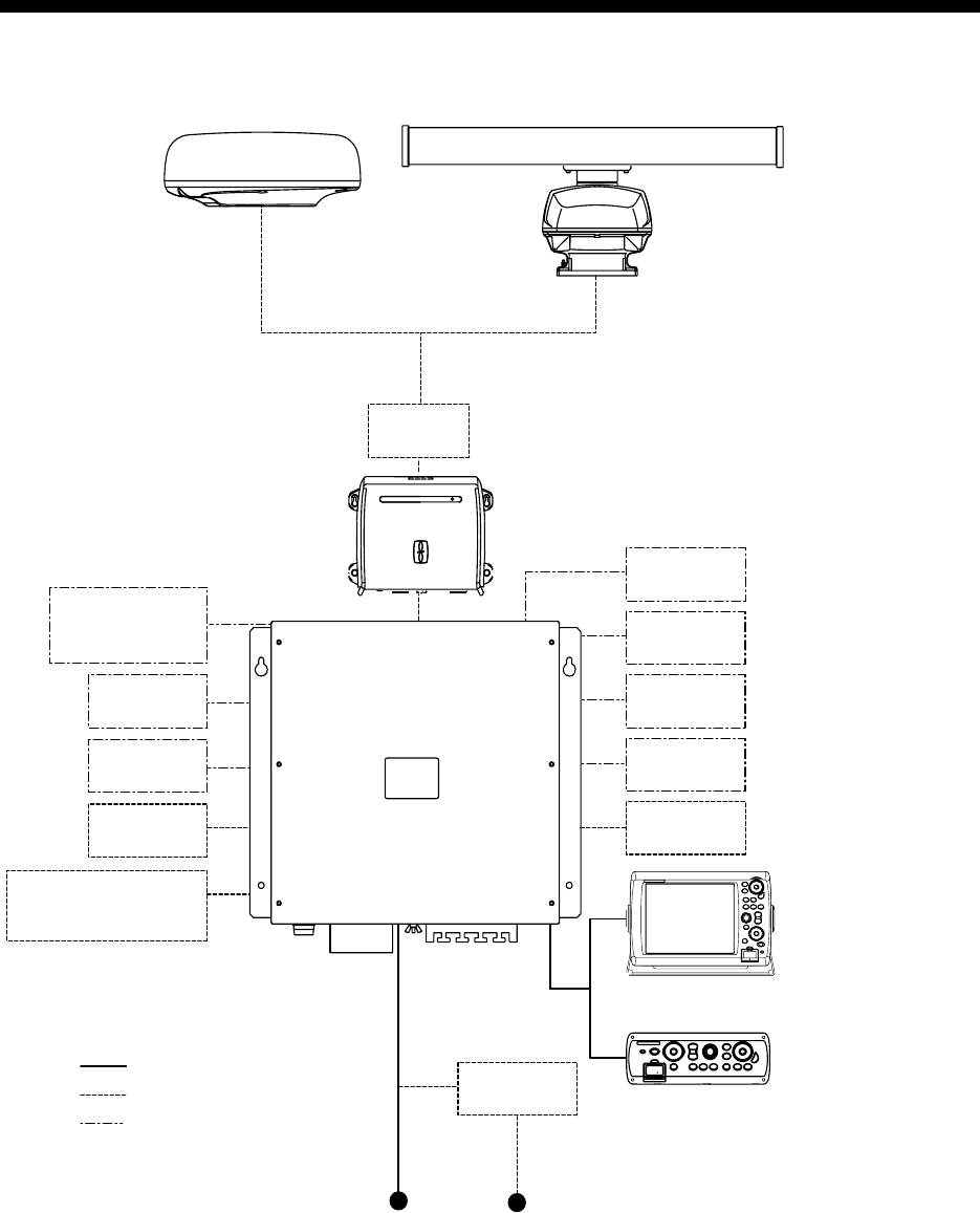
System Configuration
JOINT BOX
RADAR SENSOR
DRS4A/DRS6A/DRS12A/DRS25A
OR
RADAR SENSOR
DRS2D/DRS4D
DISPLAY UNIT
MU-155C/170C
VIDEO IN
(CCD CAMERA)
LINE OUT
(SPKR, ETC.)
RECTIFIER
RU-1746B
12-24 VDC
MIC IN
(MICROPHONE)
DISPLAY CONTROL UNIT
DCU12
CONTROL UNIT
MCU-001
AND/OR
2
HUB
GPS NAVIGATOR
GP-320B
AIS RECEIVER,
HEADING SENSOR or
EXTERNAL BUZZER
USB DEVICE
(MOUSE, KYBD)
NMEA 2000
(SENSOR, ETC.)
POWER SUPPLY UNIT
PSU-013
1
: Standard Supply
: Optional Supply
: Local Supply
1
For 25 kW radar sensor
2
Max. two units total
PROCESSOR UNIT
MPU-001
FISH FINDER
(DFF1, ETR-6/10N, ETR-30N)
(under development)
100/110/220/230 VAC
System Configuration
xiv
This page is intentionally left blank.

1-1
Chapter 1: Operational Overview
This chapter provides the information necessary to get you started using your multi
function display, from how to turn it on and off to how to read the main displays.
This manual shows dedicated keys in bold face upper case letter; for example, DISP.
All other labelled items such as ROTOkeys are shown in body text font.
1.1 Operating Controls
This multi function display comes with either the Control Unit (MCU-001) or DIsplay
Control Unit (DCU12). (Alternatively necessary software is incorporated in a PC.)
Their controls are identical except for the POWER switch; on the DCU12 it also func-
tions to adjust display brilliance.
Discrete keys whose key labels have two text labels separated by an underline carry
two functions. The top label is the main function and the bottom label, the secondary
function. You access those functions with a short push and long push, respectively.
You operate the chart plotter, radar, etc. with a combination of
• Twelve discrete keys
• Cursorpad
• Scrollingpad
•ROTOkey
• Menus, where you select options
• Pop-up menus, where you select options
• Lists, where you can edit items
When you operate a key a single beep sounds to confirm correct operation. For invalid
operation three beeps sound. If you do not need the key beep you may turn it off, in
the General menu.
Chapter 1: Operational Overview
1-2
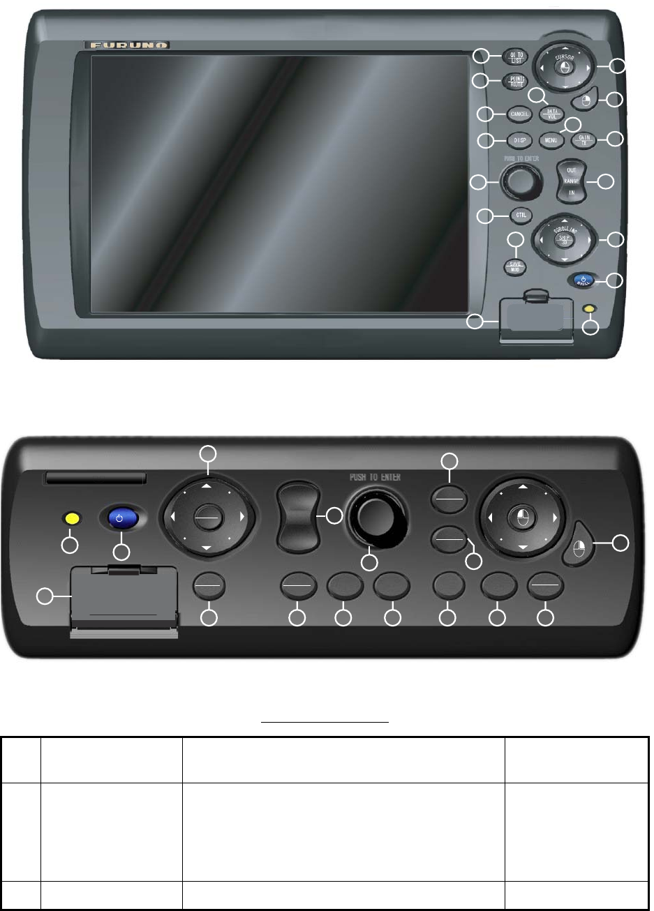
Control Description
The controls of your unit are shown in the figure below. Controls are backlit for easy
viewing in nighttime use.
DIsplay Control Unit (DCU12)
Control unit (MCU-001)
Control description
No. Label Function Key on PC or
control on mouse
1POWER Momentary press: Turn on the power; adjust
key dimmer when equipment is active. On the
DCU12 it additionally functions to adjust display
brilliance.
Long press: Turn the power on/off
F13
2 Card drive Card drive for chart cards and memory cards. None
1
2
3
4
5
6
7
8
910
11
12
13 14
15
16
17
10
5
9
CTRL
CANCEL
MENU
POINTS
SAVE
MOB DISP
GO TO
LIST
DATA
VOL
SHIP
3D
S
C
R
O
L
L
I
N
G
GAIN
TX
ROUTE
C
U
R
S
O
R
2
314 7 4 1213 6
11
8
OUT
RANGE
IN
15
16
1
17
5
9

Chapter 1: Operational Overview
1-3
3SAVE/MOB SAVE(short push): Save current position as
waypoint.
MOB(long push): Save current position as
MOB.
F2
4 CTRL key Switch active display. F6
5 Rotary Knob • Rotate to;
- display ROTOkeys
- select setting
- select option
•Push to;
- display ROTOkeys
short push to show "basic" ROTOkeys; long
push to show ROTOkey quantity selected on
the menu.
• - confirm selection
Scrollwheel. Spin or
push to display
ROTOkeys or select
option; push to con-
firm selection.
6 DISP Select display. F3
7 CANCEL key Cancel last entry (undo); silence audio alarm. Esc
8 POINTS/ROUTE POINTS(short push): Save current position as
waypoint.
ROUTE(long push): Open route building tool.
F9
9 GOTO/LIST GOTO(short push): Save current position as
waypoint.
LIST(long push): Open route building tool.
F8
10 Cursorpad • Pad: Shift cursor.
•: Like the "click" button on a PC mouse.
Hereafter referred to as "left-button key".
• Drag mouse.
• Left mouse button.
11 ((Right-button
key)
Show/erase pop-up menu. Hereafter referred to
as "right-button key".
Right mouse button
12 DATA/VOL DATA(short push): Show/hide NavData.
VOL(long push): Change audio level.
F7
13 MENU Open/close menu. F4
14 GAIN/TX GAIN(short push): Adjust radar gain.
TX(long push): Toggle between standby and
transmit for radar.
F5
15 RANGE OUT,
RANGE IN
Choose range on chart and radar. F10: RANGE OUT
F11: RANGE IN
16 Scrollingpad • Pad: Scroll chart; offcenter radar picture.
•SHIP/3D button: Momentary push to center
vessel; long push to alternately enable and
display the 3D display.
• Left and right
mouse buttons.
•F12
17 Power lamp Lights in green when power is on –
Control description
No. Label Function Key on PC or
control on mouse
Chapter 1: Operational Overview
1-4
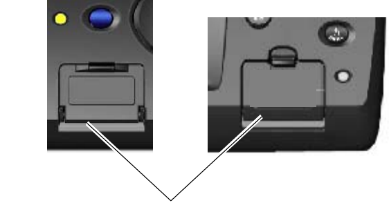
1.2 Inserting, Removing a Chart Card
Before turning on the power, insert the chart card for your area in the card drive. Your
multi function display can read C-MAP NT MAX/MAX2, Mapmedia and S52 cards.
Inserting a Chart Card
1. Open the card drive lid at the lower left side of Control Unit MCU-001, or the lower
right side of the Display Control Unit DCU12.
2. Insert chart card label side up in one of the slots. It will go in only if oriented and
inserted correctly.
3. Close the lid. You will hear a click when the lid is correctly closed.
Removing a Chart Card
1. Open the card drive lid.
2. Push in the card. The card will pop half way out. Pull out the card.
3. Close the lid. You will hear a click when the lid is correctly closed.
Precautions with Chart Cards
• Do not remove a card while the chart is being drawn. This can cause the equipment
to freeze.
• Do not insert or remove a card while the power is on. This can cause the equipment
to freeze.
• Keep the lid closed at all times to keep foreign material and water out of the card
drive.
• Remove, insert and store the card with care. Rough handling can damage the card
and destroy its contents.
DCU12MCU-001
Card drive
Chapter 1: Operational Overview
1-5
1.3 Turning the Power On/Off
Press the power switch to turn the power on. To turn the power off, press and hold
down the switch until the screen goes blank.
Shortly after the power is applied the lamp below the power switch lights (in green)
and the start-up screen appears. Then, the application program no. for the MPU-001
(Processor Unit) and the application and boot program nos. for the MCU-001 and/or
DCU12 are shown.
1.4 Adjusting Display Brilliance, Key Dimmer
The brilliance of the DCU12’s display can be adjusted, with the POWER/BRILL key.
1. Push the POWER/BRILL key to display the LCD brilliance and key dimmer adjust-
ment window.
2. Rotate the Rotary Knob to select the item you wish to adjust and push the Rotary
Knob.
3. Rotate the Rotary Knob to adjust item selected; clockwise rotation to raise bril-
liance(dimmer) or counterclockwise to lower brilliance(dimmer). Eight levels of
brilliance and dimmer are available.
4. Push the Rotary Knob to confirm setting.
Chapter 1: Operational Overview
1-6
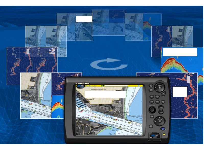
1.5 Selecting a Display
Use the DISP key and ROTOkey to select a display. The displays available depend
on the equipment you have in your NavNet system. In a later chapter you will learn
how to customize the display selection to suit your needs and system configuration.
1. Press the DISP key to show the display selection window. (The labels in the illus-
tration below do not appear on the actual display.)
Display selection window
2. Rotate the Rotary Knob to place the display desired inside the on-screen display
unit.
3. Push the Rotary Knob to confirm selection.
Switching Active Display in Combination Displays
Use the CTRL key to switch active display in combination displays. Each time the key
is operated the active display is switched and the active display is circumscribed with
a yellow square.
FISH FINDER DISPLAY
(under development)
RADAR
DISPLAY
CHART PLOTTER DISPLAY
PIP DISPLAY
Chapter 1: Operational Overview
1-7
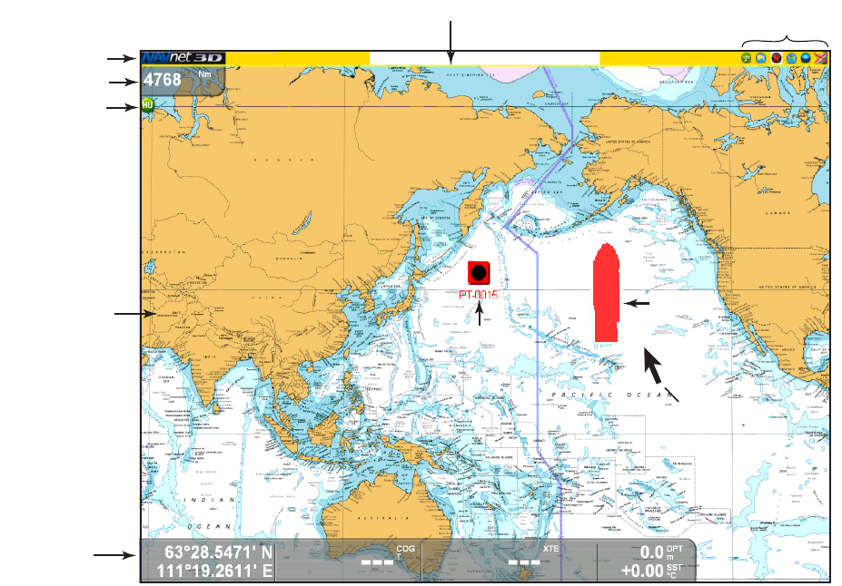
1.6 Chart Plotter Display Overview
The chart plotter display provides a miniature world map. Detailed chart information is
available when a chart card is inserted. The plotter section has facilities for waypoint
entry and route construction and planning. A typical chart plotter display is shown in
the illustration below.
The chartplotter uses position information fed from position-fixing equipment such as
GPS or DGPS. With position data available, your boat’s position is marked on screen
with a boat icon, the configuration of which can be selected from the menu. If no head-
ing or course data is available, your boat is shown as a hollow circle (flashing).
Waypoints and routes you have entered are shown on the display, and they can easily
be moved, deleted and edited from a pop-up menu.
In addition to waypoint and route processing, the chart plotter also provides informa-
tion to nearest port, displays your boat’s track, measures distances and bearings,
marks man overboard (MOB) position, process various alarms, follow simple and
complex routes, etc.
Chart scale
Presentation
mode selection
icon
Nav
data
World
map
Status bar
Waypoint
Boat icon
(red)
Cursor
Text message area Sensor icons
Chapter 1: Operational Overview
1-8
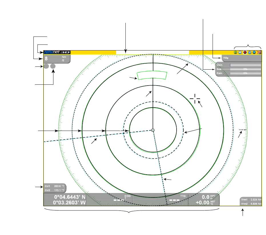
1.7 Radar Display Overview
A radar system operates in the ultra-high-frequency (UHF) or microwave part of the
radio-frequency (RF) spectrum, and is used to detect the position and movement of
objects. Objects are shown on the radar display at their measured distances and bear-
ings, in intensities according to echo strength.
The radar display is available in head-up, course-up and north-up modes and orienta-
tion in true and relative motion. Relative motion shows other ships movement relative
to own ship, True motion shows own ship and other moving objects moving in accor-
dance with their true courses and speed.
Dual VRMs are provided to measure the range to objects, and dual EBLs to measure
the bearing to targets. A guard zone can be created to be alerted to targets in a spe-
cific area. The trail of targets can be shown in afterglow to monitor their movement.
Range, range ring interval
Status bar
Presentation
mode icon
Motion mode
icon
Fixed range
rings
EBL box
(normally
hidden)
Nav data VRM box
(normally
hidden)
EBL1
EBL2
VRM2
VRM1
Heading
line
Guard
zone
Heading
Window for adjustment of
gain, sea and rain clutter
(normally hidden)
Text message area
Sensor icons
Cursor
+
HU TM
90.0°T
North
marker
Chapter 1: Operational Overview
1-9
1.8 Common Operations
Moving the Cursor
The cursor is the pointer you see on your display. Its main functions are
• Find a position on the display
• Select an item; for example, waypoint on the chart plotter
To move the cursor, press on any of the four arrows on the Cursorpad to move the
cursor in the direction indicated on the arrow pressed. You may also move the cursor
diagonally by pressing and holding down on any two locations together on the pad.
The current cursor position is shown in the cursor position box at the bottom of the
screen, if it is displayed.
Cursor position box
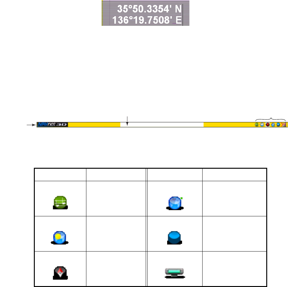
Status Bar
The status bar is the yellow horizontal bar at the top of the display. It provides operat-
ing information with text messages and sensor status with icons. Text (operational
help, alarm alert, etc.) runs across the text message area from right to left, tickertape
style. When an alarm is violated, the bar turns red and the name of the offending alarm
appears in the text message area.
The mode icons at the far right hand side show active and inactive sensors. An icon
is animated if the corresponding sensor is active. An inactive sensor (or no data) has
a red "X" through it.
Icon Sensor Icon Sensor
Multimedia GPS
Weather Fish Finder
(under development)
Compass Radar
S
tatus bar
Text message area Mode icons
Chapter 1: Operational Overview
1-10
ROTOkeys
The ROTOkeys are like "soft keys"; they change according to active display. The RO-
TOkeys are hidden until you elect to display them. To display the ROTOkeys, simply
rotate or push the Rotary Knob, and they appear at the right edge of the screen. By
long-pushing the Rotary Knob you can display a greater quantity of ROTOkeys. In the
default set up a short push shows the "basic" set and a long push shows the "stan-
dard" set. A "full" set and "custom" set are also available.
The ROTOkeys are auto-hiding, and are erased from the screen if not operated within
about six seconds. They can also be manually hid by using the CANCEL key.
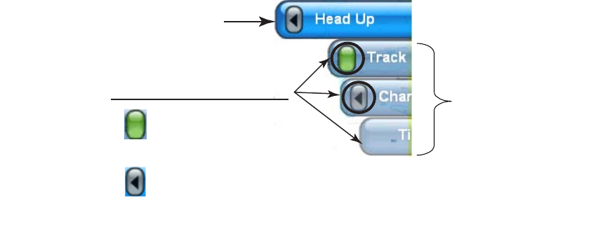
There are three categories of ROTOkeys: Single level, multi-level and specialty
display.
To select a ROTOkey for adjustment do the following:
1. Rotate or push the Rotary Knob to show the ROTOkeys. (Long-push the knob to
show the "standard" keys. These keys can also be activated when the "basic"
keys are shown.) In the example below, a few of the basic ROTOkeys for the chart
plotter are shown.
Basic ROTOkeys for chart plotter
2. Rotate the Rotary Knob to select the ROTOkey you wish to use.
As you step through the ROTOkey selections, the active ROTOkey is magnified
and blue and inactive ones are grey.
3. Do one of the following depending on category of ROTOkey.
Single level: Push the Rotary Knob to color the status indicator (left of the
ROTOkey label) green to turn on the respective item, or gray to turn it off.
Multi-level: Push the Rotary Knob, rotate it to select desired ROTOkey and push
it to confirm selection.
Specialty display: Push the Rotary Knob to show the display whose name
appears on the ROTOkey label.
Active ROTOKey (magnified and blue)
Inactive ROTOKey (gra
y
ROTOKey category identifier
: Multi-level
: Single level
ON: Green
OFF: Gray
No box: Specialty display