Furuno USA 9ZWRTR103 Transceiver for Radar Sensor DRS4W User Manual
Furuno USA Inc Transceiver for Radar Sensor DRS4W
User Manual

RADAR SENSOR
DRS4W
OPERATOR'S MANUAL
www.furuno.com
Model
TENTATIVE
TENTATIVE

The paper used in this manual
is elemental chlorine free.
・FURUNO Authorized Distributor/Dealer
9-52 Ashihara-cho,
Nishinomiya, 662-8580, JAPAN
A
:
APR
2012
.
Printed in Japan
All rights reserved.
C
:
APR
.
10, 2013
Pub. No.
OME-44730-C
(
DAMI
)
FMD-3200/3200BB/3300
0 0 0 1 7 6 1 2 5 1 2
TENTATIVE
Z1 : MAR. 6, 2014
Pub. No. OME-36360-Z1
DRS4W

i
IMPORTANT NOTICES
General
How to discard this product
Discard this product according to local regulations for the disposal of industrial waste. For disposal
in the USA, see the homepage of the Electronics Industries Alliance (http://www.eiae.org/) for the
correct method of disposal.
How to discard a used battery
Some FURUNO products have a battery(ies). To see if your product has a battery, see the chapter
on Maintenance. Follow the instructions below if a battery is used. Tape the + and - terminals of
battery before disposal to prevent fire, heat generation caused by short circuit.
In the European Union
The crossed-out trash can symbol indicates that all types of batteries
must not be discarded in standard trash, or at a trash site. Take the
used batteries to a battery collection site according to your national
legislation and the Batteries Directive 2006/66/EU.
In the USA
The Mobius loop symbol (three chasing arrows) indicates that Ni-Cd
and lead-acid rechargeable batteries must be recycled. Take the used
batteries to a battery collection site according to local laws.
In the other countries
There are no international standards for the battery recycle symbol. The number of symbols can
increase when the other countries make their own recycle symbols in the future.
• This manual has been authored with simplified grammar, to meet the needs of international users.
• The operator of this equipment must read and follow the descriptions in this manual. Wrong oper-
ation or maintenance can cancel the warranty or cause injury.
• Do not copy any part of this manual without written permission from FURUNO.
• If this manual is lost or worn, contact your dealer about replacement.
• The contents of this manual and equipment specifications can change without notice.
• The example screens (or illustrations) shown in this manual can be different from the screens you
see on your display. The screens you see depend on your system configuration and equipment
settings.
• Save this manual for future reference.
• Any modification of the equipment (including software) by persons not authorized by FURUNO will
cancel the warranty.
Trademark Notices
• All brand and product names are trademarks, registered trademarks or service marks of their re-
spective holders.
• Apple, iPad and iPhone are registered trademarks of Apple, Inc.
• App Store is a registered service mark of Apple, Inc.
• iOS is a registered trademark of Cisco Systems, Inc.
Cd
PbNi-Cd
TENTATIVE
ii
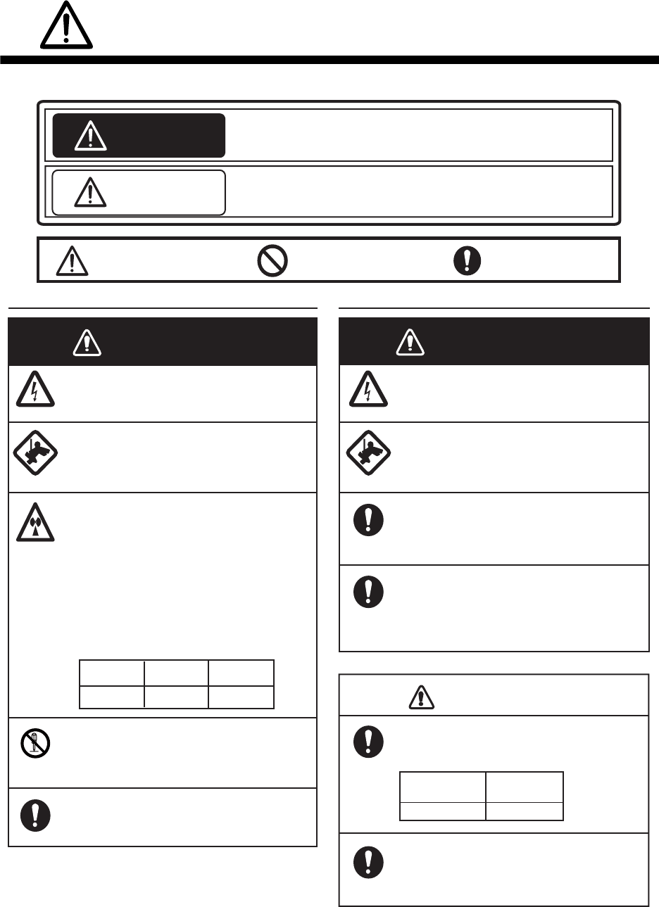
SAFETY INFORMATION
Read these safety instructions before installing or operating the equipment.
WARNING
Indicates a potentially hazardous situation which, if not avoided,
can result in minor or moderate injury.
Warning, Caution Prohibitive Action
CAUTION
Mandatory Action
Indicates a potentially hazardous situation which, if not avoided,
can result in serious injury or death.
Safety Information for the Operator Safety Information for the Installer
Wear a safety belt and hard hat when
working on the antenna unit.
Serious injury or death can result if
someone falls from the radar mast.
Do not open the equipment.
The installation does not require you
to open the radar sensor.
Be sure the power source is compatible
with the voltage rating of the equipment.
Connection of an incorrect power source
can cause fire or damage the equipment.
Turn off the power at the power source
before beginning the installation.
Fire, electrical shock or serious injury can
result if the power is left on or is applied
while the equipment is being installed.
WARNING
WARNING
ELECTRICAL SHOCK HAZARD
Do not open the equipment.
There are no user servicable parts inside.
The radar antenna emits electromag-
netic radio frequency (RF) energy
which can be harmful, particularly to
your eyes. Never look directly into the
antenna aperture from a close distance
while the radar is in operation or
expose yourself to the transmitting
antenna at a close distance.
Distances at which RF radiation levels of
100, 50 and 10 W/m2 exist are given in
the table below.
100 W/m210 W/m2
N/A 0.0 m
Do not disassemble or modify the
equipment.
Fire, electrical shock or serious injury can
result.
Wear a safety belt and hard hat when
working on the antenna unit.
Serious injury or death can result if
someone falls from the radar mast.
NOTICE
Observe the following compass safe
distance to prevent interference to a
magnetic compass.
It is recommended that you connect
the sensor to a disconnecting device
(circuit breaker, etc.) to control the
power.
Standard
compass
1.45 m 0.90 m
Steering
compass
50 W/m2
N/A
Use the proper fuse.
Use of a wrong fuse can damage the
equipment or cause fire.
TENTATIVE
SAFETY INFORMATION
iii
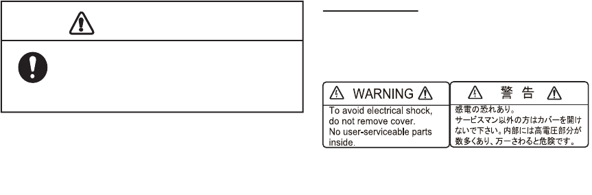
WARNING LABEL
A warning label is attached to the sensor. Do not
remove the label. If the label is missing or
damaged, contact a FURUNO agent or dealer
about replacement.
NOTICE
Do not expose the radar sensor to
strong water jets.
Excessively strong water jets can damage
the sensor.
Name: Warning Label (2)
Type: 03-129-1001-3
Code No: 100-236-743
TENTATIVE

iv
TABLE OF CONTENTS
FOREWORD ........................................ v
1. OPERATION ................................. 1
1.1 System Overview ........................1
1.2 How to Start, Stop the System ....1
1.3 Transmit, Standby .......................2
1.4 Display Layout.............................2
1.5 Touch Screen Operations ...........3
1.6 Picture Menu ...............................3
1.7 How to Adjust the Screen Tone ..4
1.8 How to Select a Display Range...4
1.9 How to Reduce Rain Clutter........4
1.10 How to Measure the Bearing and
Range to a Target (iPad only) .....4
1.11 How to Off Center the Display.....5
1.12 Echo Stretch................................5
1.13 Palette .........................................5
1.14 Echo Color ..................................6
1.15 Picture Format.............................6
1.16 How to Take a Screenshot of
the Display ..................................6
1.17 Settings Menu .............................6
2. MAINTENANCE,
TROUBLESHOOTING...................8
2.1 Maintenance ...............................8
2.2 Replacement of Fuse..................8
2.3 Troubleshooting ..........................9
2.4 Error Messages...........................9
2.5 Replacement of Magnetron.........9
2.6 Self Test....................................10
3. INSTALLATION ...........................11
3.1 Equipment List ..........................11
3.2 Installation Considerations........11
3.3 How to Install the
Radar Sensor............................12
3.4 How to Set up the
Radar Sensor............................15
3.4.1 How to start the system.....15
3.4.2 Heading, timing
adjustment .........................15
3.4.3 Range unit .........................17
3.4.4 Tuning initialization ............17
3.4.5 Sector blank.......................17
APPENDIX 1 MENU TREE............ AP-1
APPEDNIX 2 RADIO REGU-
LATORY INFORMATION .............. AP-2
SPECIFICATIONS ..........................SP-1
INDEX ..............................................IN-1
TENTATIVE
v
FOREWORD
A Word to the Owner of the
DRS4W
Congratulations on your choice of the
FURUNO RADAR SENSOR DRS4W.
Since 1948, FURUNO Electric Company has
enjoyed an enviable reputation for innovative
and dependable marine electronics equip-
ment. This dedication to excellence is fur-
thered by our extensive global network of
agents and dealers.
This equipment is designed and constructed
to meet the rigorous demands of the marine
environment. However, no equipment can
perform its intended function unless installed,
operated and maintained properly. Please
carefully read and follow the recommended
procedures for installation, operation, and
maintenance.
We would appreciate hearing from you, the
end-user, about whether we are achieving our
purposes.
Thank you for considering and purchasing
FURUNO.
Features
• Complies with wireless LAN standard
IEEE802.11b.
• Radar sensor forwards radar echoes to an
iPad or iPhone via the 2.4 GHz radio band.
• Compatible with the following iOS terminals
(iOS 6.1.3, 7.0.4 or higher):
• iPhone 5, 5c, 5s
• iPad 2, 3, 4, mini
• Stylish radome-type radar sensor.
• Echoes shown in green or yellow, or
multicolor in red, yellow or green, corre-
sponding to strong, medium and weak
echoes.
• 14 ranges from 0.125 to 24 NM.
• Screen tone adjustable to suit lighting con-
ditions.
• Two iOS terminals can be connected to the
radar sensor at the same time.
• Echo stretch lengthens echoes in range
and/or bearing direction.
• Automatic adjustment of sea clutter (ech-
oes from waves), gain, noise and interfer-
ence.
• Off center feature lets you look focus on a
specific area ahead of or around your ves-
sel without losing track of position.
• Self test checks the radar sensor for correct
operation.
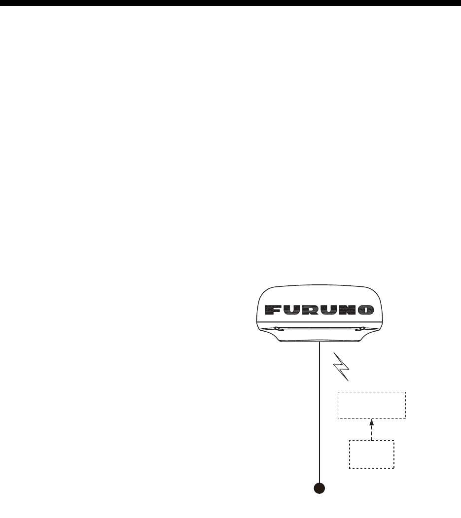
System Configuration
RADAR SENSOR
DRS4W
Power supply
12/24 VDC
Wireless LAN (WLAN)
2.4 GHz
iOS Terminal
(iPad, iPhone)
AC/DC
Adapter
TENTATIVE
1
1. OPERATION
1.1 System Overview
The radar sensor transmits pulses of micro-
wave energy that bounce off any object in
their path. The object returns a tiny part of the
wave's energy to the radar sensor. Radar de-
termines the distance to a target by calculat-
ing the time difference between the trans-
mission of a radar signal and the reception of
the reflected echo. The bearing to a target
found by the radar is determined by the direc-
tion in which the antenna is pointing when it
emits an electronic pulse and then receives a
returning echo.
The radar sensor forwards the returning ech-
oes to the iOS terminal (iPhone, iPad), using
its wireless LAN module. The radar applica-
tion in the iOS terminal displays the radar ech-
oes on the terminal’s display and provides
controls for adjustment of the radar picture.
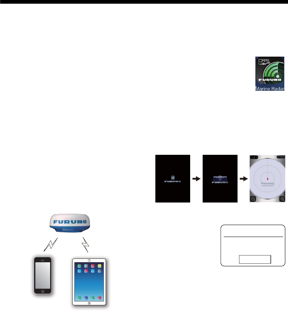
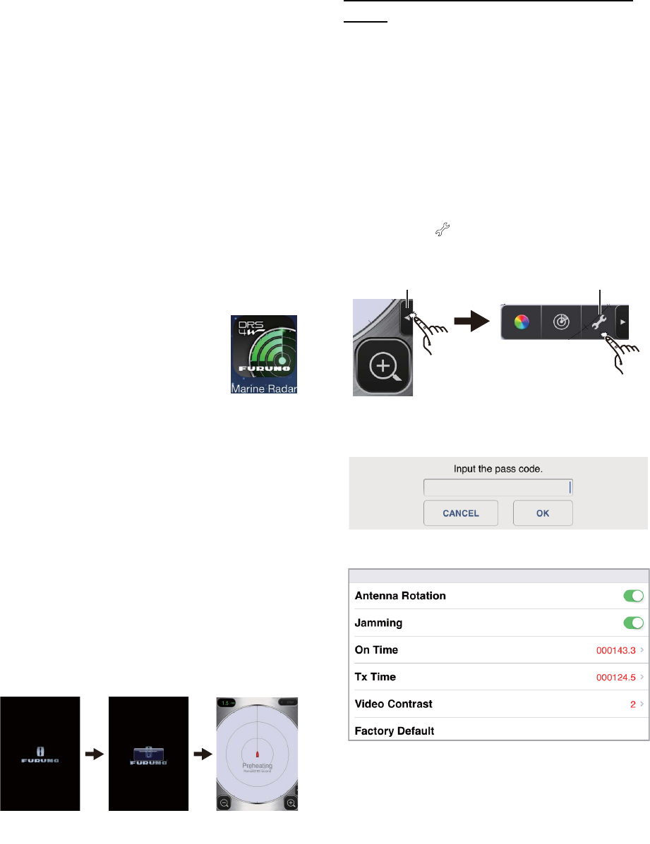
1.2 How to Start, Stop
the System
Power the radar sensor to acti-
vate the system. Open your iPad
or iPhone terminal and click the
[Marine Radar] application icon
(see right figure).
The splash screen appears for a few mo-
ments, then the application tries to connect to
the radar sensor, which normally takes no
more than three seconds. If the connection is
successful, the [Preheating] display appears.
If the connection
failed, the window
shown right appears.
Tap the [Search
again] button to try to
connect to the radar
sensor. If you cannot connect to the radar
sensor, check for interfering objects near the
sensor and make sure the wireless LAN func-
tion is enabled on your terminal.
The preheating stage, which warms the mag-
netron (the device responsible for transmitting
radar pulses), takes approx. 90 seconds. The
time remaining until the completion of the pre-
heating is counted down at the center of the
screen. After the completion of the preheat-
ing, the STBY display appears.
To deactivate the system, disconnect the ra-
dar sensor from the power source.
Note: To connect an iOS terminal to another
DRS4W, reset the application first.
Radar sensor
iPhone
iPad
Wireless LAN
2.4 GHz
Wireless LAN
2.4 GHz
Splash
screen
Searching
radar sensor
Preheating
display
Radar sensor
communciation error!
E0002: Please check WLAN
connection setup, and power is
applied to radar sensor.
Search again
TENTATIVE
1. OPERATION
2
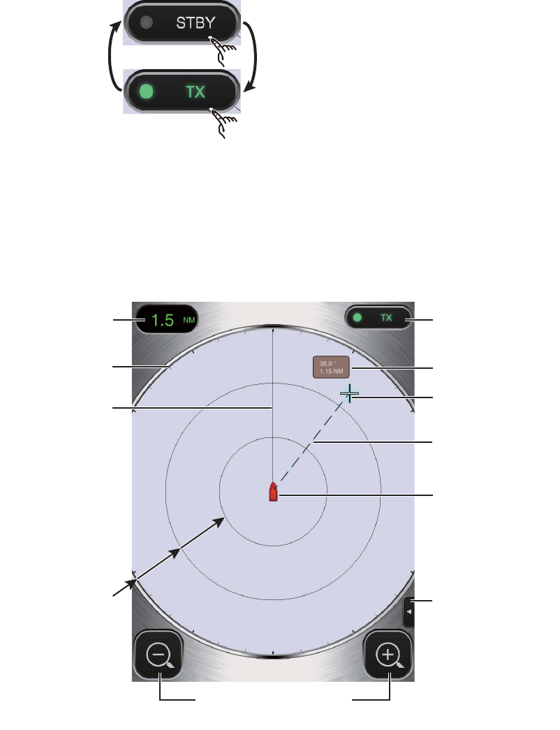
1.3 Transmit, Standby
Tap the [STBY-TX]
icon at the top right
corner on the screen
to put the radar in
standby, transmit
state alternately.
When you don’t need the radar, set it to stand-
by to extend the life of the magnetron.
Note: The radar application is set to standby
when you switch to another application, or
there is no operation for one minute. Howev-
er, the picture is continuously updated. The
notifications banner, which alerts you to re-
ceived mail, etc., works while the radar appli-
cation is active.
1.4 Display Layout
The figure below shows all the indications, markers and icons that appear on the iPad radar dis-
play. The layout on the iPhone is similar.
STBY-TX icon
Menu tab*
Fixed range rings
Display range
Heading line
Range selection buttons
Cursor*
Own ship mark
Bearing, range box*
Bearing scale
Bearing line*
* Not provided on iPhone.
TENTATIVE
1. OPERATION
3
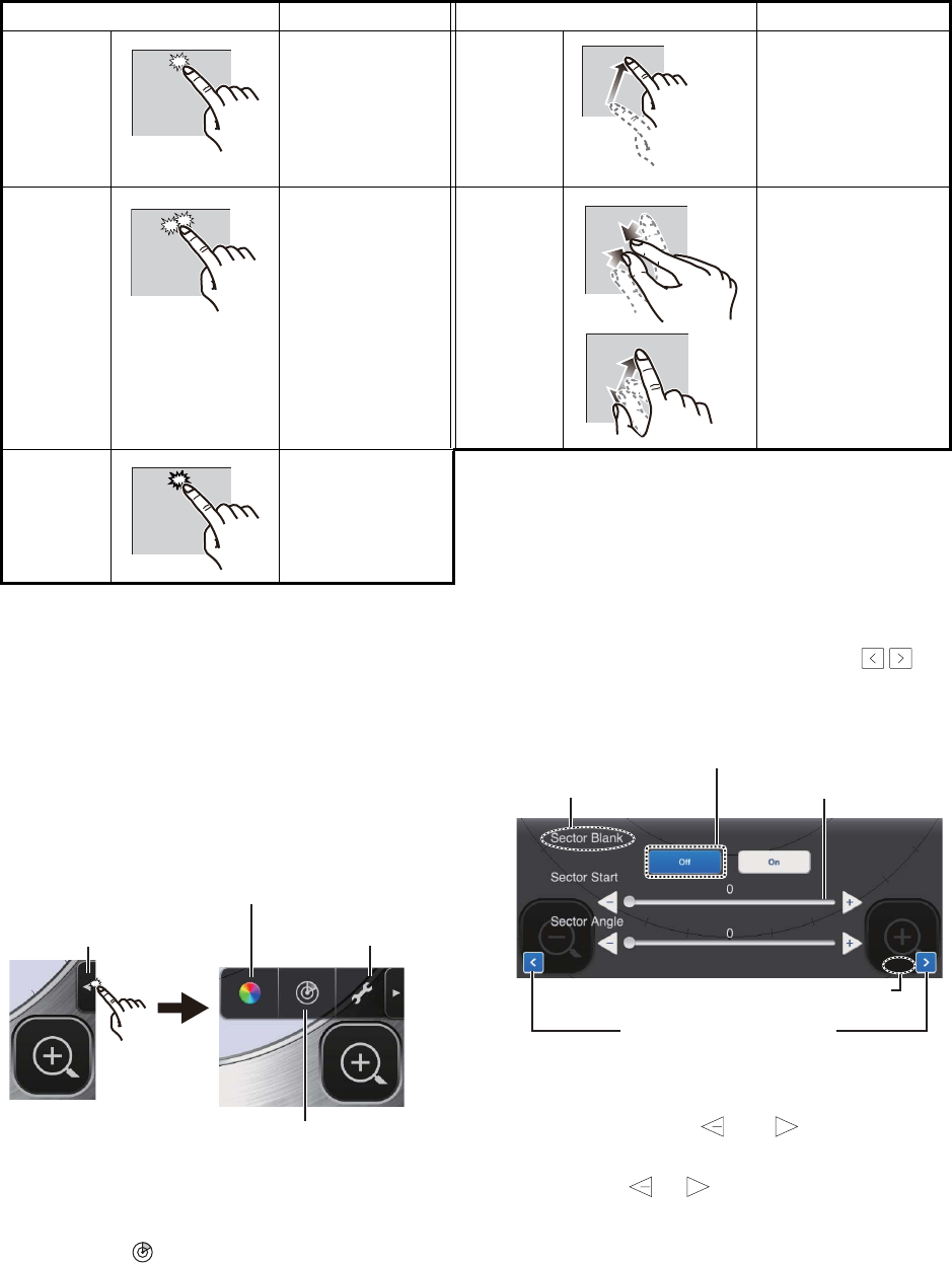
1.5 Touch Screen Operations
The table below shows all the basic touch screen operations.
1.6 Picture Menu
This sensor has three menus: Picture, Color,
and Settings.The Picture menu contains the
most frequently used radar functions.
1. iPad: Tap the Menu tab at the right side of
the screen to show the menu.
iPhone: Tap anywhere to show the
menu.
2. Tap the ( ) icon to activate the [Picture]
menu.
3. Use the page selection buttons ( ) to
browse the items of the menu. For exam-
ple, select [Sector Blank].
4. The [Picture] menu has several types of
controls for adjustment.
Slider bar with and buttons: Drag
the slider bar to adjust the item selected.
Use the or button to fine tune the
setting.
Function buttons: Tap the appropriate
button to select the function labeled on
the button.
5. To close the menu, tap anywhere outside
the menu area.
Operation Action Operation Action
Tap • Open, close
menus.
• Operate vari-
ous buttons.
Drag • Move the cur-
sor.*
• Move slider bar
in menus.
• Off center the
display.
Double
tap
• Cancel off
center dis-
play.
Pinch in,
Pinch out
• Select display
range.
Long
push
(approx.
2 sec.)
• Display the
cursor.*
* The iPhone does not have a cursor.
Color menu icon
Picture menu icon
Settings menu icon
Menu tab
/
Slider bar
Item name
Page selection buttons
Item no./Item total
Function button
3 / 3
+
+
TENTATIVE
1. OPERATION
4
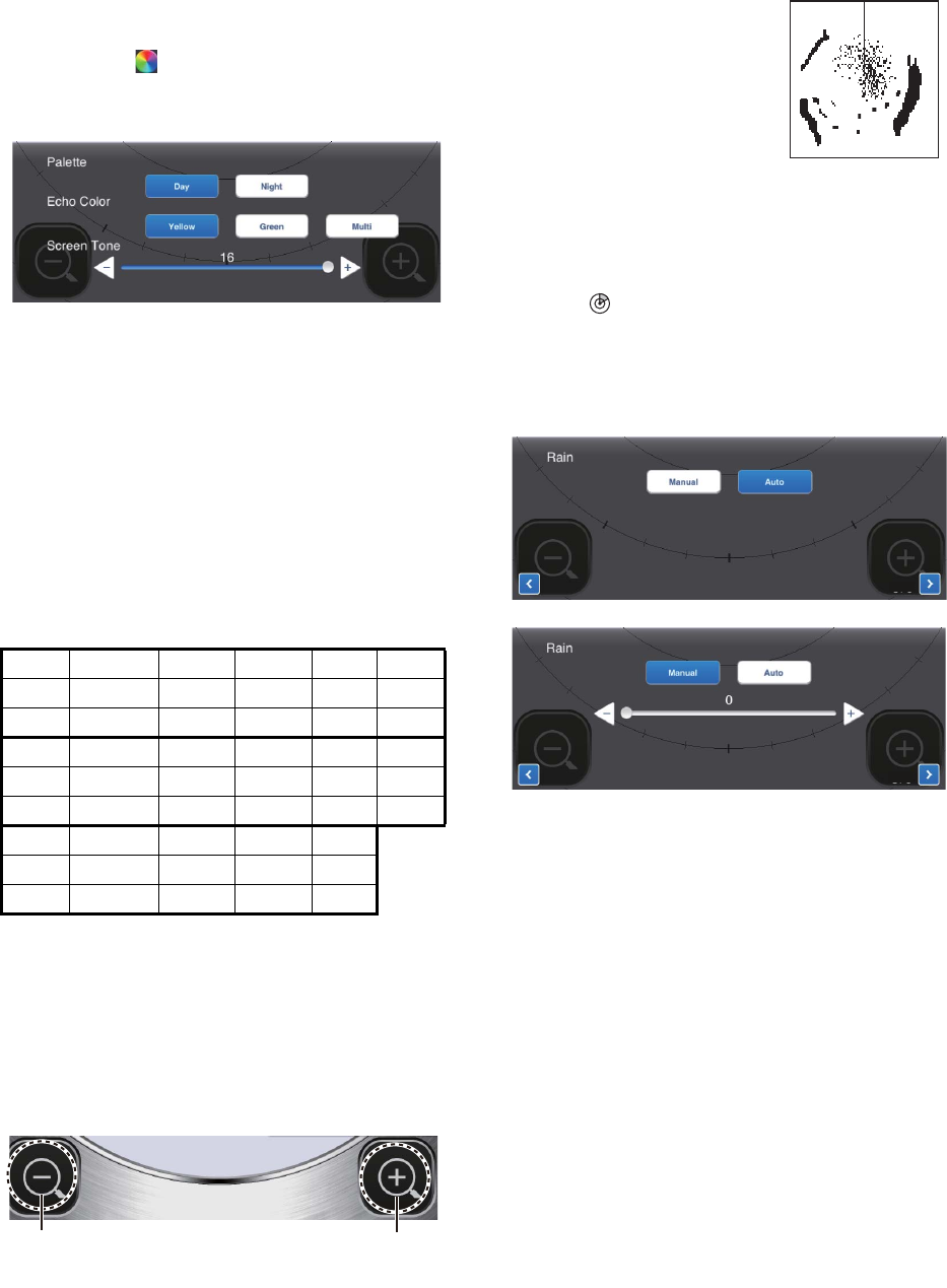
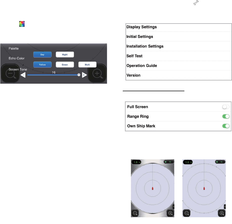
1.7 How to Adjust the
Screen Tone
The screen tone (brightness) can be adjusted
to suit lighting conditions. Open the menu
then tap the ( ) icon. Drag the slider bar to
adjust the screen tone.
1.8 How to Select a
Display Range
The range selects how far you want the radar
to “see”. The range selected automatically de-
termines the range ring interval, the number
of range rings and pulse repetition rate. The
current range is shown at the top left corner
on the screen.
R: Display range, FRR: Fixed range ring
interval, NR: Number of fixed range rings
To select a display range, tap the range selec-
tion buttons at the bottom right and left cor-
ners. Alternatively, you can pinch in or pinch
out within the display area.
1.9 How to Reduce
Rain Clutter
The antenna picks up rain
clutter (rain, snow, or hail) in
the same manner as normal
targets, as in the right fig-
ure. When rain clutter
masks targets, use the
[Rain] control to reduce the
clutter. The higher the setting the greater the
reduction of rain clutter
To adjust the rain clutter, open the menu then
tap the ( ) icon. Select the [Rain] screen.
Tap the [Manual] or [Auto] button. For manual
adjustment, drag the slider bar to reduce the
rain clutter.
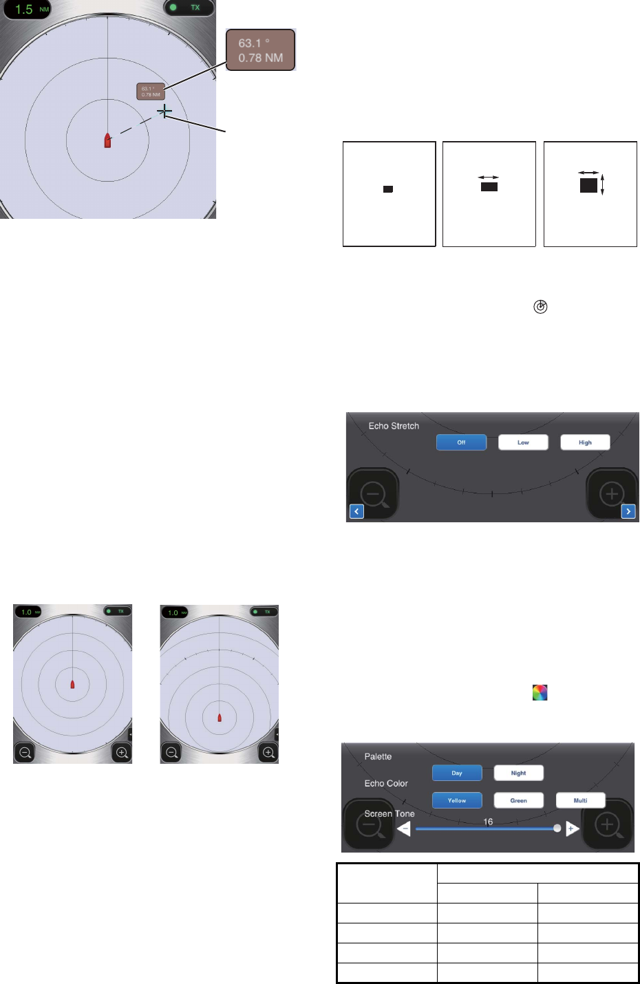
1.10 How to Measure
the Bearing and
Range to a Target
(iPad only)
The bearing and range from own ship to a tar-
get can be measured with the cursor. Long
push the screen to show the cursor, which is
a cross (+). Drag the cursor to put it on the
center of the target. See the bearing and
range to the target in the [Bearing/Range]
box, which is to the side of the cursor. After
several seconds, the cursor is erased from
the screen.
R 0.125 0.25 0.5 0.75 1
FRR 0.0625 0.125 0.125 0.25 0.25
NR 2 2 4 3 4
R1.5 2 3 46
FRR 0.5 0.5 1 1 2
NR 3 4 3 4 3
R 8 12 16 24
FRR 2 3 4 6
NR 4 4 4 4
Decrease the range
(zoom in)
Increase the range
(zoom out)
Manual adjustment
Automatic adjustment
1 / 3
1 / 3
TENTATIVE
1. OPERATION
5
Note: A slight difference exists between fin-
ger position and cursor position in order to
see the cursor while dragging it.
1.11 How to Off Center
the Display
Own ship position, or sweep origin, can be
displaced manually or automatically to ex-
pand the view without switching to a longer
range. The maximum amount of shift is 75%
of the range in use.
To off center the display, drag the own ship
mark to the position you want to make the
screen center. To return to the normal display,
double tap the display area.
1.12 Echo Stretch
On long ranges, target echoes tend to shrink,
making them difficult to see. To enhance tar-
get video on long ranges, use the echo stretch
feature to lengthen echoes in the bearing
and/or range direction.
Open the menu then tap the ( ) icon. Select
the [Echo Stretch] screen. Select [Low] to
lengthen echoes in the bearing direction;
[High] to lengthen echoes in both the bearing
and range directions.
1.13 Palette
The palette feature changes the color of the
background, characters, range rings and
heading line to suit the time of day, daytime or
nighttime.
Open the menu then tap the ( ) icon. Select
[Day] or [Night] as appropriate.
Bearing,
range to
cursor
Cursor
Normal display Off centered display
Item Color
Day Night
Background White Black
Characters Gray Red
Rings Gray Red
Heading line Gray Red
Echo Brg dir. Brg dir.
Rng
dir.
Echo stretch
OFF
Echo stretch
Low
Echo stretch
High
2 / 3
TENTATIVE
1. OPERATION
6
1.14 Echo Color
Echoes can be shown in yellow, green, or
multicolor. Multicolor paints each radar echo
in a color according to its strength, in red, yel-
low or green, corresponding to strong, medi-
um and weak echoes. Open the menu then
tap the ( ) icon. Select the color desired at
[Echo Color].
1.15 Picture Format
You can show the radar picture in landscape
or portrait format. Rotate your terminal to
change the format.
1.16 How to Take a
Screenshot of the
Display
You can take a screenshot of the radar dis-
play, and save it to the Photos folder in your
terminal. Push the Home and Power buttons
together. You should hear the camera shutter
sound.
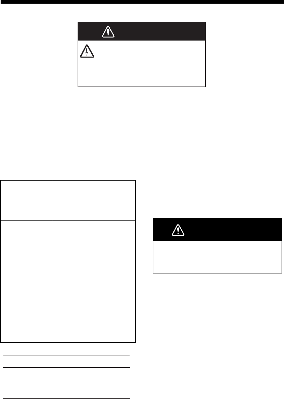
1.17 Settings Menu
The [Settings] menu contains items that once
preset do not require frequent adjustment.
Open the menu then tap the ( ) icon to open
the [Settings] menu.
Display Settings menu
[Full Screen]: Turn the full screen display on
or off.
[Range Ring]: The range rings are the con-
centric circles about own ship position, and
they function to provide an estimate of the
range to a target. You can turn the rings on or
off here.
[Own Ship Mark]: The own ship mark is
shown at the display center and indicates
your current position. You can turn the mark
on or off here.
(Version no. appears here)
Full screen ONFull screen OFF
TENTATIVE

1. OPERATION
7
Initial Settings menu
[Units]: Select the unit of range measure-
ment, nm or km.
[Tune Initialize]: Automatically tune the radar
receiver. See the chapter on installation.
Installation Settings menu
The items in this menu are mainly intended for
the serviceman. See the chapter on installa-
tion.
Self Test
Tests the radar sensor and radar application
for proper operation. See the chapter on
Maintenance.
Operation Guide
Operator’s guide to the basic functions of this
radar.
Version
Shows the software version no.
Units
Tune Initialize
nm
>
TENTATIVE
8
2. MAINTENANCE,
TROUBLESHOOTING
2.1 Maintenance
Regular maintenance is important for good
performance. Check the points mentioned be-
low every 3 to 6 months to keep the radar sen-
sor in good working order. Observe the safety
instructions at the front of this manual when
working on the mast.
2.2 Replacement of
Fuse
The 5A fuse (Type: FGBO 250V 5A PBF,
Code No.: 000-155-840-10) in the fuse holder
on the power cable protects the radar sensor
from overcurrent and equipment fault. If you
cannot turn on the power, check the fuse to
see if it has blown. If the fuse has blown, find
the reason before you replace the fuse. If the
fuse blows again after the replacement, con-
tact your dealer for advice.
WARNING
DO NOT OPEN THE SENSOR.
Electrical shock hazard
There are no user-serviceable parts
inside. Only qualified personnel are
allowed to work inside the equipment.
Check point Action
Check fixing
bolts for corro-
sion and if tightly
fastened.
Tighten loosened bolts.
Replace corroded bolts.
Coat new bolts with marine
sealant.
Check radome
for cracks,
foreign material.
If a crack is found, repair it
temporarily with a small
amount of sealing com-
pound or adhesive. Bring
the unit to your dealer for
permanent repairs.
Foreign material on the
radome can cause a
considerable drop in sensi-
tivity. Remove foreign
material with a freshwater-
moistened cloth. Do not
use commercial cleaners to
clean the sensor; they can
remove paint and markings
or deform the plastic.
Do not apply paint, anti-corrosive sealant
or contact spray to coating or plastic parts.
Those items contain organic solvents that can
damage coating and plastic parts.
NOTICE
WARNING
Use the proper fuse.
Use of the wrong fuse can damage the equip-
ment or cause fire.
TENTATIVE
2. MAINTENANCE, TROUBLESHOOTING
9
2.3 Troubleshooting
The table below provides simple trouble-
shooting procedures that the user can follow
to restore normal operation. If you cannot re-
store normal operation, contact your dealer
for advice.
2.4 Error Messages
Error messages are shown to alert you to ra-
dar sensor problems. The table below shows
the error messages and accompanying mes-
sage numbers and check points. These alerts
appear in the background; no notification is
given.
2.5 Replacement of
Magnetron
The life expectancy of the magnetron is ap-
prox. 5,000 hours (including standby). The ef-
fectiveness of the magnetron decreases over
time, causing lower-than-normal signal
strength and loss of echoes. If you feel the
signal strength is low, contact your dealer
about replacement of the magnetron.
Trouble Remedy
The power
cannot be
turned on.
• Check if the power cable is
connected to the power
source and the power
source is on.
• Check the power cable for
damage.
• Check if the fuse has blown.
The power is
on but noth-
ing appears
on the
display.
Try adjusting the brightness
with [Brightness] in the
[Settings] menu in your termi-
nal, or [Screen Tone] in the ra-
dar application.
The display
freezes.
• Restart the application.
• Reset your terminal.
You cannot
connect to
the wireless
LAN but you
can see the
host on the
terminal.
• Switch between standby
and transmit.
• Restart the application.
• Check the WLAN settings in
your terminal.
• Restart your terminal.
Message Message no. and
check point
"No radar
sensor
found!"
E0001: Please check WLAN
connection setup, and power
is applied to radar sensor.
"Radar sen-
sor communi-
cation error!"
E0002: Please check WLAN
connection setup, and radar
sensor condition.
"Radar sen-
sor signal
error!"
E0003: Heading pulse of
radar sensor is not detected.
Please check radar sensor
condition.
E0004: Video pulse of radar
sensor is not detected.
Please check radar sensor
condition.
Name Type Code no.
Magnetron E3571 000-126-646
TENTATIVE
2. MAINTENANCE, TROUBLESHOOTING
10
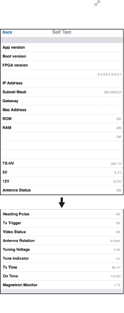
2.6 Self Test
The self test is for use by the service techni-
cian to check the equipment. However, the
user can do the test to support the service
technician.
1. Open the menu then tap the ( ) icon.
2. Tap [Self Test] to do the self test.
The result for [ROM], [RAM], [WLAN Status]
and [Antenna Status] is [OK] or [NG] (No
Good). If [NG] appears for an item, try the test
again. If [NG] appears again, contact your
dealer for advice.
WLAN=Wireless LAN
Actual value appears in place of “x”.
WLAN FW version
WLAN Status
WLAN Channel
WLAN Power
15dBm
03593929-xx.xx
03593930-xx.xx
0359313-xxxxxxx-xx
172.31.x.xx
172.31.x.xx
xx-xx-xx-xx-xx-xx
x
Scroll
TENTATIVE
11
3. INSTALLATION
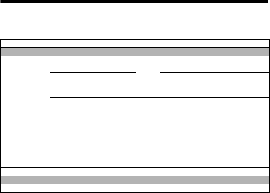
3.1 Equipment List
3.2 Installation Considerations
Name Type Code No. Qty Remarks
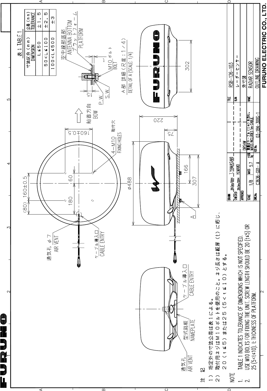
Standard supply
Radar Sensor RSB-126-103 - 1
Installation
Materials
CP03-35800 000-024-974 Select
one
Power cable assy., 10 m
CP03-35810 000-024-975 Power cable assy., 15 m
CP03-35820 000-024-976 Power cable assy., 20 m
CP03-35830 000-024-977 Power cable assy., 30 m
CP03-35701 001-265-920 1 - Hex bolt*(M10×25), 4 pcs.
- Flat washer (M10 SUS304), 4 pcs.
- Spring washer (M10 SUS304), 4 pcs.
*For use if thickness of platform is
6–10 mm.
Documents OME-36360 - 1 Operator’s Manual
MDC-36360 - 1 C-ROHS list
E32-01314 - 1 Template
E32-01401 - 1 SSID, password information
Spare Parts SP03-17801 001-265-910 1 5A fuse, 2 pcs.
Optional supply
Radome Mount OP03-209 001-078-350 1 Mast mounting bracket for sailboat
General considerations:
• Do not apply paint, anti-corrosive sealant or contact spray to coating or plastic parts. Those items
contain solvents that can damage coating and plastic parts.
• The radar sensor has no power switch. Therefore, it is recommended that you connect the sensor
to a disconnecting device (circuit breaker, etc.) to control the power.
Sensor placement:
• The radar sensor uses the 2.4 GHz wireless LAN radio band to forward radar echoes to the iOS
terminal. Separate the sensor well away from products which also use this band (microwave
range, Bluetooth devices, etc.) to prevent mutual interference.
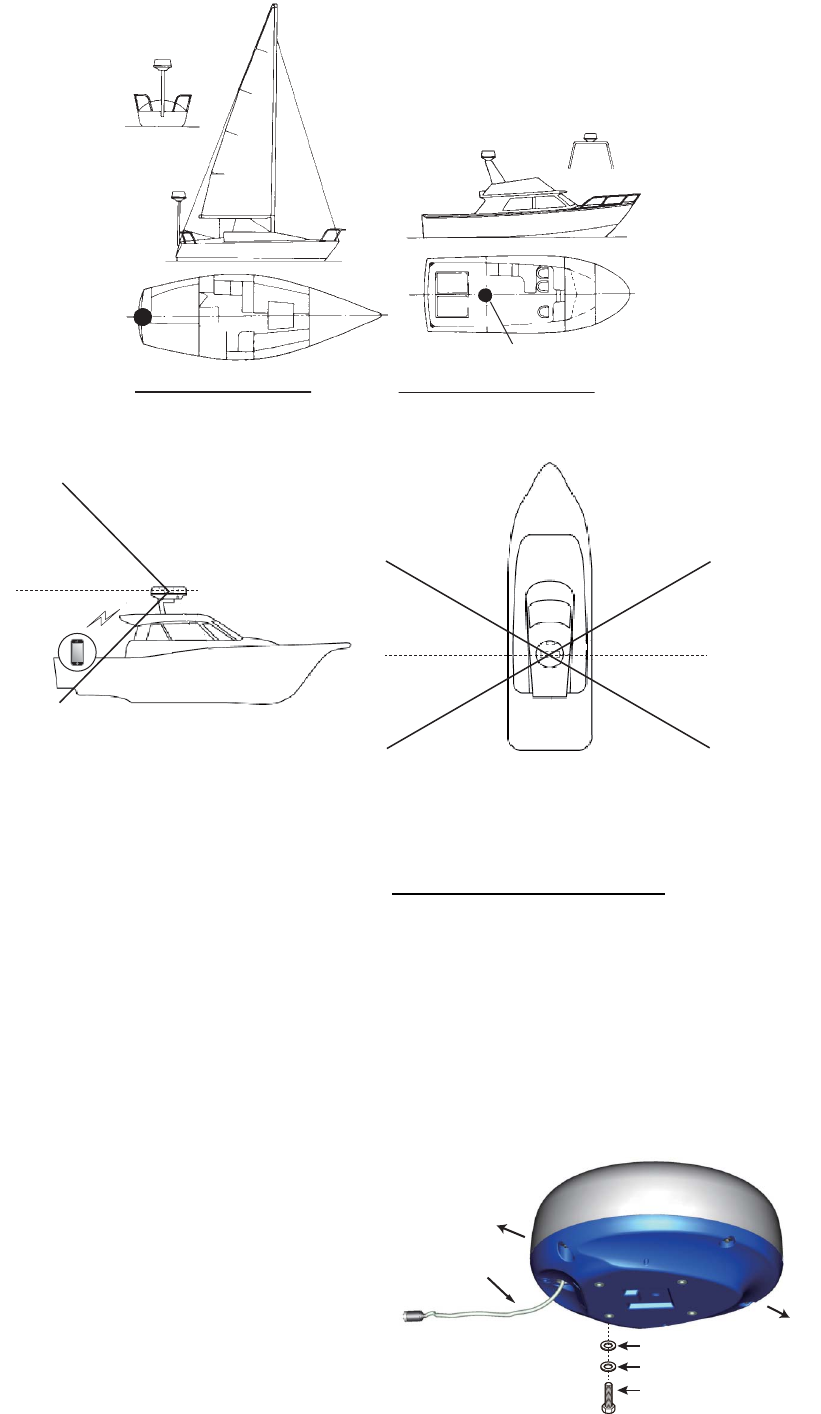
• Install the radar sensor on the hardtop, radar arch or on a mast on an appropriate platform. (For
sailboats, a “radome mount” is optionally available for fixing the sensor to a mast.) Place the sen-
sor where there is a good all-round view with, as far as possible, no part of the ship’s superstruc-
ture or rigging intercepting the scanning beam. Any obstruction will cause shadow and blind
sectors. Be sure there are no metallic objects near the antenna. See the next page for typical
placement on a sailboat and powerboat.
• Observe the wireless LAN communication range noted in the illustration on the next page.
• In order to reduce the chance of picking up electrical interference, avoid where possible routing
the power cable near other electrical equipment onboard. Also, avoid running the cable in parallel
with other power cables.
• Select a location that does not allow water to accumulate at the base of the sensor.
• A magnetic compass will be affected if the radar sensor is too close to the compass. Observe the
compass safe distances mentioned on page ii to prevent interference to a magnetic compass.
TENTATIVE
3. INSTALLATION
12
3.3 How to Install the
Radar Sensor
Determine the suitability of the mounting loca-
tion BEFORE permanently mounting the sen-
sor. Incoming and outgoing signals may
overlap one another depending on the shape
of the vessel, preventing communication be-
tween the terminal and the sensor. Set the
sensor on the selected location and connect
the sensor to the power source. Turn on the
sensor. Open the terminal, turn on the radar
application and try to connect the terminal to
the sensor (see section 3.4.1 for how to start
the system). If the connection is successful,
change the range to check if the sensor re-
ceives your command. Check that the picture
is updated with each sweep. Some trial and
error may be necessary to find a suitable loca-
tion.
Installation on a platform
1. Remove the mounting hardware at the
bottom of the radar sensor - four each of
hex bolts (M10×20), spring washers and
flat washers. Save the spring washers
and flat washers to use them to fasten the
radar sensor to the platform, at step 4. If
the thickness of the platform is 5 mm or
less, also save the bolts.
Radar
sensor
Radar
sensor
Installation on a sailboat
Radar
sensor
Radar sensor
Installation on a powerboat
45°
60°
Weak signal
area
30°
30°
Location and wireless LAN communication range
Typical installation on a sailboat, power boat
Strong signal area
Strong signal area
Weak signal
area
Strong signal area
Strong signal
area
iPhone
Weak signal
area
Weak signal
area
Weak signal
area
Hex bolt
Spring washer
Flat washer
STERN
BOW
Power
cable
TENTATIVE
3. INSTALLATION
13
2. Construct a platform (steel or aluminum)
referring to the outline drawing and the
mounting template. Fasten the platform to
the mounting location. The holes in the
platform must be parallel with the fore and
aft line.
3. Put the radar sensor on the platform with
the bow mark (U) on sensor aligned with
the bow.
4. Use hex bolts*, flat washers and spring
washers (removed at step 1) to fasten the
radar sensor to the platform. The torque
for the bolts must be 19.6 to 24.5 N•m.
*See the figure below to determine bolt
length to use.
5. Connect the supplied power cable to the
sensor. Observe the guidelines for laying
the power cable shown on this page.
6. Connect the power cable to the power
source.
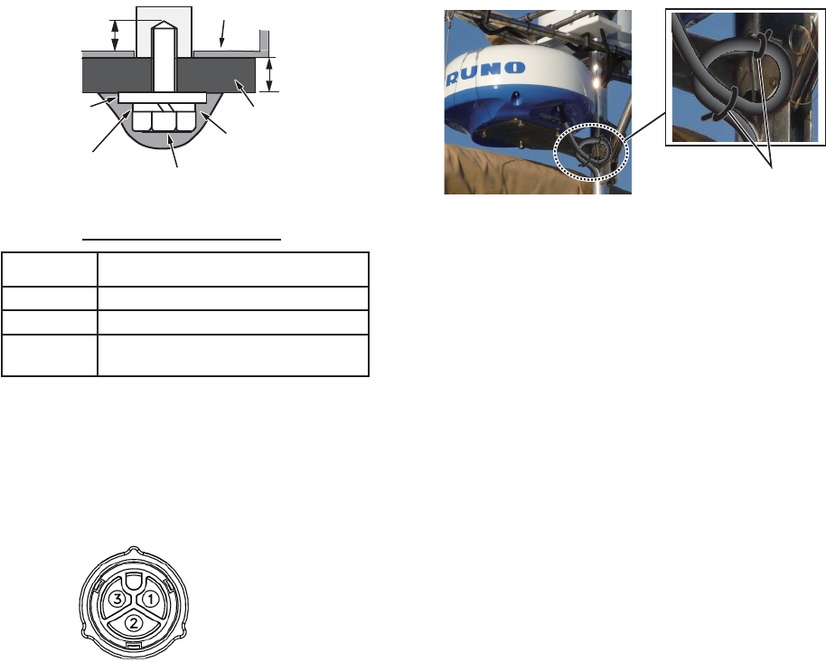
Guidelines for laying the power cable
• The connectors must not strike any part of
the vessel by wind, etc.
• The load applied to the connectors must
not be more than its own weight.
• If the cable is passed through a mast on a
sailboat, be sure the cable does not touch
ropes (sheet, halyard, etc.).
• Do not fasten the cable to the hull.
• The cable must be fixed so no tension is ap-
plied to the connectors. To prevent tension,
create a loop in the cable close to the sen-
sor and tie the loop with cable ties, as in the
figure below.
• Wrap the junction of the connectors with
self vulcanizing tape for waterproofing.
• Fasten the cable to the mast, etc. at the
neck of each connector with a cable tie.
Flat
washer
Sensor base assy.
Platform
Hex bolt
(See below.)
Apply marine
sealant.
L
Spring
washer
Platform thickness and bolt to use
Platform
thickness Bolt to use
5 mm or less M10×20 (Supplied, prefastened to radome.)
6 - 10 mm M10×25 (Supplied.)
Over 10 mm Use bolt where the length of “L” above is
15 mm. Supply locally.
1: Red
2: Braid
3: Blue
Power cable
pin assignment
Loop cable and tie
loop with cable ties.
TENTATIVE
3. INSTALLATION
14
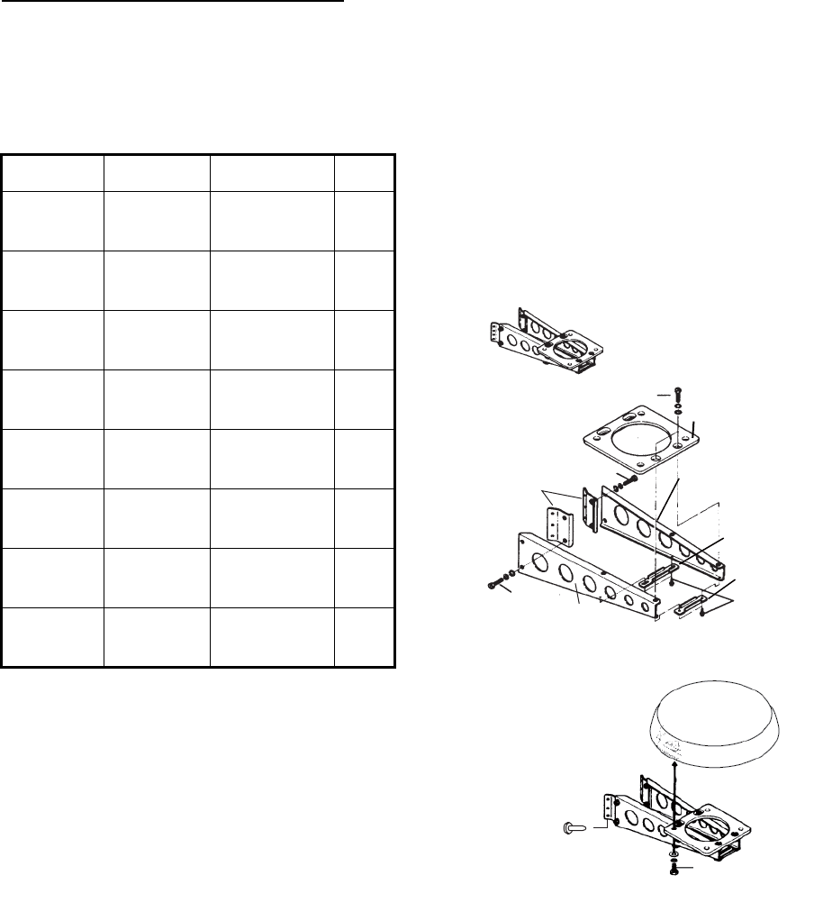
Installation with the radome mount
The optional radome mount lets you fasten
the radar sensor to a mast on a sailboat.
Name, Type: Radome Mount, OP03-209
Code No.: 001-078-350
How to assemble the bracket
1. Fasten the fixing plates to brackets (1)
and (2) with four M8×20 hex bolts.
2. Fit brackets (1) and (2) loosely with sup-
port plates (1) and (2) using four M4×12
hex bolts, so that the gap between the
brackets can be adjusted.
3. Place the mounting plate on the bracket
and fix it loosely with four M8×20 hex
bolts.
How to fasten the bracket to the mast
1. Drill eight holes of 6.5 mm diameter in the
mast and fix the bracket with eight stain-
less steel rivets (local supply) of 6.4 mm
diameter.
2. Tighten the bolts on the bracket.
3. Fasten the radar sensor to the bracket.
Connect the power cable to the power source,
observing the guidelines for laying the power
cable shown on this page.
Name Type Code No. Qty
Mounting
plate
03-018-
9001-0
100-206-
740-10
1
Support
plate (1)
03-018-
9005-0
100-206-
780-10
1
Support
plate (2)
03-018-
9006-0
100-206-
790-10
1
Bracket
(1)
03-028-
9101-1
100-206-
811-10
1
Bracket
(2)
03-028-
9101-2
100-206-
812-10
1
Fixing
plate
03-028-
9103-1
100-206-
831-10
2
Hex bolt
w/washer
M8×20
SUS304
000-162-
955-10
8
Hex bolt
w/washer
M4×12
SUS304
000-162-
956-10
4
Mounting plate
Support
plate (1)
Support
plate (2)
Bracket (1)
Fixing
plate
M8×20
ASSEMBLED
RADOME MOUNT
M8×20
M8×20
M4×12
How to assemble the radome mount
Rivet
M10×25
How to fasten the sensor to the radome mount
Bracket (2)
TENTATIVE
3. INSTALLATION
15
3.4 How to Set up the
Radar Sensor
Before you can set up and use the radar sen-
sor, download and install the free application
[Marine Radar] from the App Store. The appli-
cation is common to both the iPad and the
iPhone.
Set up the radar as shown in this section, in
the order given.
An insert sheet requests you to attach the
supplied SSID and password label to the in-
sert sheet. Attach the label to the sheet, and
store the sheet in a safe place for future refer-
ence.
3.4.1 How to start the system
Power the sensor. Open your iOS
terminal, then turn on the wireless
LAN function (in the [Settings]
menu) if it is not already on. Tap
the [Marine Radar] application
(see right figure, appearance subject to
change) in your terminal.
The splash screen appears for a few mo-
ments, then the application tries to connect to
the radar sensor, which normally takes no
more than three seconds. If the connection is
successful, the [Preheating] display appears.
If the connection could not be made, an error
message appears. Tap the [Search again]
button to try to connect to the sensor. If the
application cannot connect to the sensor,
check to see if the wireless LAN function is
enabled on your terminal.
After the preheating is completed, which
takes approx. 90 seconds, the radar goes into
standby. Tap the STB-TX icon at the top right
corner on the display to transmit.
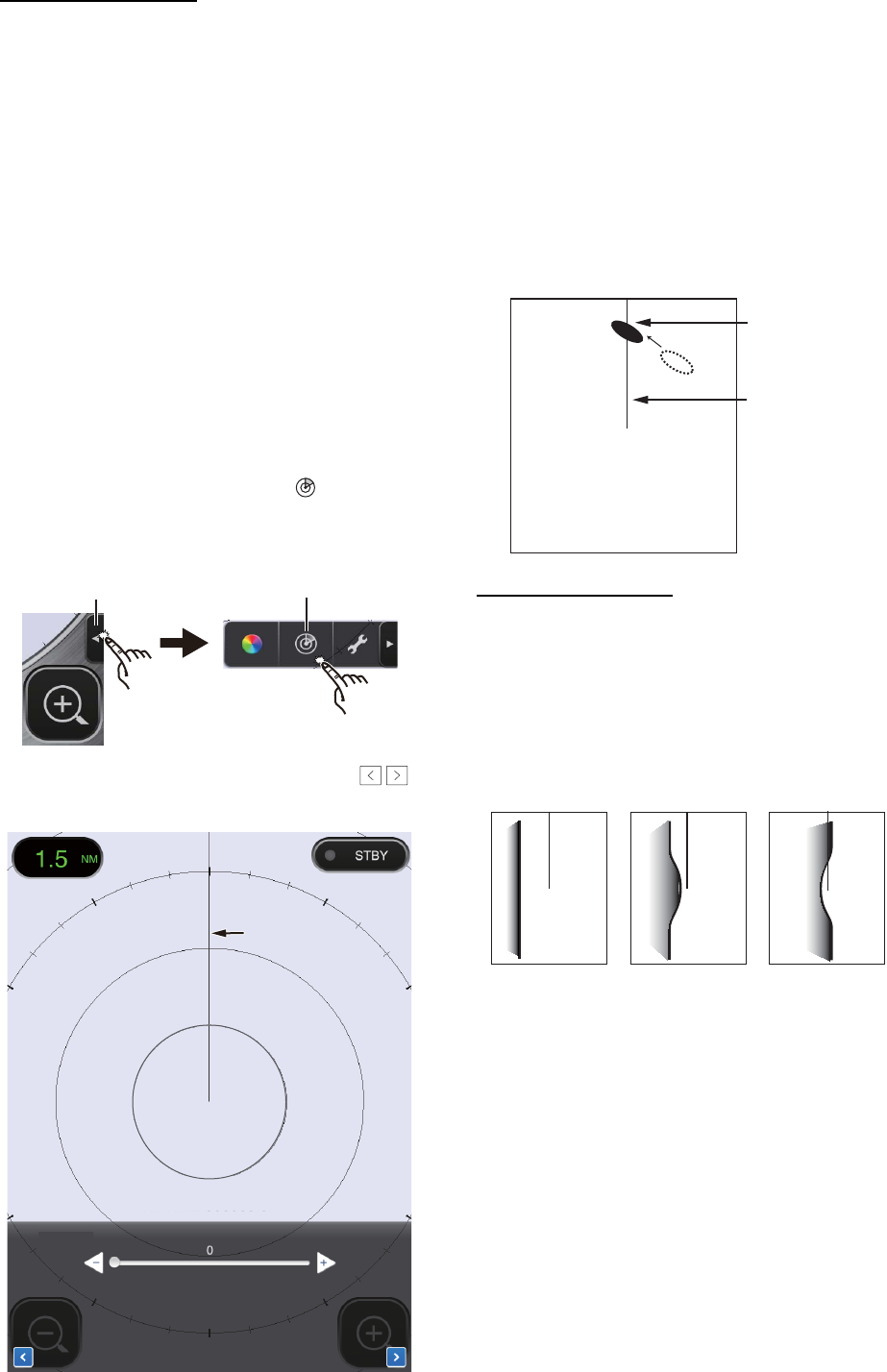
3.4.2 Heading, timing
adjustment
How to open the Installation Settings
menu
To adjust the heading or timing, you must first
open the [Installation Settings] menu.
1. Open the menu, Settings menu:
1) iPad: Tap the menu tab at the bottom
right corner to open the menu.
iPhone: Tap anywhere to open the
menu.
2) iPad, iPhone: Tap the Settings menu
icon ( ) to show the Settings menu.
2. Tap [Installation Settings]. You are asked
to input the pass code.
3. Use the software keyboard to enter 1234.
4. Tap [Back] twice to close the menu and
return to the radar display.
Splash
screen
Searching
radar sensor
Preheating
display
Menu tab
Settings
menu icon
How to open the Settings
menu on the iPad
TENTATIVE
3. INSTALLATION
16
Heading alignment
You have mounted the radar sensor facing
straight ahead in the direction of the bow.
Therefore, a small but conspicuous target
dead ahead visually should appear on the
heading line (zero degrees).
In practice, you will probably observe some
small error on the display because of the diffi-
culty in achieving accurate initial positioning
of the sensor. The following adjustment com-
pensates for this error.
1. Open the menu, Picture menu:
1) iPad: Tap the menu tab at the bottom
right corner to open the menu.
iPhone: Tap anywhere to open the
menu.
2) iPad, iPhone: Tap the ( ) icon to
open the Picture menu.
2. Tap the menu navigation buttons ( )
to select [Heading Align].
3. Visually identify a suitable target (for ex-
ample, ship or buoy) at a range between
0.125 to 0.25 miles.
4. Point your boat’s bow directly toward the
target selected at step 3.
5. Locate the target selected at step 3 on the
display and choose a range which places
the target in the outer half of the picture.
6. Adjust the slider bar so the target be-
comes centered on the heading line.
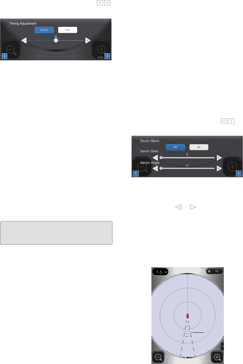
Timing adjustment
The timing is automatically adjusted. Howev-
er, if a “straight” target (harbor wall, etc.) ap-
pears to be pushed or pulled, as shown
below, adjust the sweep timing to straighten
the target and prevent incorrect placement of
all targets.
1. Transmit on a range between 0.125 and
0.5 nm.
2. Open the Picture menu, referring to step
1 in “Heading alignment”.
Menu tab
Picture
menu icon
How to open the Picture
menu on the iPad
/
Heading line
Heading line
Heading Align (0~359)
3 / 5
Heading line
Tar ge t
Correct Target pushed
inward
Target pushed
outward
TENTATIVE
3. INSTALLATION
17
3. Tap the menu navigation buttons ( )
to select [Timing Adjustment].
4. Select [Manual] or [Auto]. For [Auto] go to
step 7. For [Manual] go to step 5.
5. Find a target which should be displayed
“straightly” (harbor wall, straight pier) on
the radar display.
6. While looking at the target selected at
step 5, operate the slider bar to straighten
the target.
7. Tap the display area to close the window.
3.4.3 Range unit
The range can be shown in nautical miles or
kilometers, and the default setting is nautical
miles. To change the unit, do as follows:
1. Open the Settings menu, referring to step
1 in “How to open the [Installation Set-
tings] menu” on page 15.
2. Tap [Initial Settings].
3. Tap [Units] then select range unit.
3.4.4 Tuning initialization
Tuning is automatically adjusted when the ra-
dar transmits, therefore initialization is not
necessary. (Initialization is necessary only
when the magnetron is replaced.)
3.4.5 Sector blank
A sector blank is an area on the radar display
where no radar echoes appear because an
obstruction near the radar sensor (for exam-
ple, a mast) blocks reception within that area.
This area should be marked on the display to
alert you that no echoes will be shown there.
If you do not have this problem, skip this pro-
cedure.
As an example, the procedure below shows
how to set a 20° sector blank between 170°
and 190°.
1. Open the Picture menu, referring to step
1 in “Heading alignment” on page 16.
2. Tap the item selection buttons ( ) to
select [Sector Blank].
3. Tap the [On] button.
4. At [Sector Start], drag the slider bar to set
the start bearing relative to the heading
line. (Use the or button to fine tune
the setting.) In the example, set “170”.
5. At [Sector Angle], drag the slider bar to
set the width of the sector. In the exam-
ple, set “20”.
The sector is marked on the display with
dashed green lines.
To disable the sector, tap [Off] at [Sector
Blank].
/
Heading Align (0~359)
3 / 5
Units
Tune Initialize
nm
>
/
5 / 5
+
Sector
blank
Sector
blank
TENTATIVE
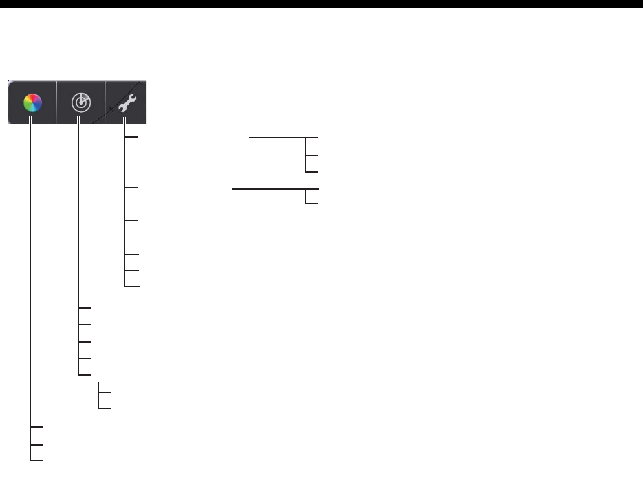
AP-1
APPENDIX 1 MENU TREE
Rain (Manual, 0~100; Auto)
Echo Stretch (Off, Low, High)
Heading Align (0.0~359.9°)
Timing Adjustment* (Manual, Auto)
Sector Blank* (Off, On)
Settings
menu
Settings
menu
Picture
menu
Picture
menu
Color
menu
Color
menu
Display Settings
Initial Settings
Installation Settings (Antenna Rotation, Jamming,
On Time, Tx Time, Video Contrast, Factory Default)
Self Test
Operation Guide
Version
Units (nm, km)
Tune Initialize
Full Screen (Off, On)
Range Ring (Off, On)
Own Ship Mark (Off, On)
Sector Start (0~359°)
Sector Angle (0~135°)
Palette (Day, Night)
Echo Color (Yellow, Green, Multi)
Screen Tone (0-16)
* Shown when Installation Setting menu is activated.
TENTATIVE

AP-2
APPENDIX 2 RADIO REGULATORY
INFORMATION
Wireless interoperability
This product is designed to be interoperable with any wireless LAN product that is based on direct
sequence spread spectrum (DSSS) and orthogonal frequency division multiplexing (OFDM) radio
technology and to comply with the following standards.
• IEEE Std 802.11b Standard on 2.4 GHz Wireless LAN
• IEEE Std 802.11g Standard on 2.4 GHz Wireless LAN
• IEEE Std 802.11n Standard on 2.4 GHz Wireless LAN
Safety
This product, like other radio devices, emits radio frequency electromagnetic energy. The level of
energy emitted by this device, however, is less than the electromagnetic energy emitted by other
wireless devices such as mobile phones. This product operates within the guidelines found in ra-
dio frequency safety standards and recommendations. These standards and recommendations
reflect the consensus of the scientific community and result from deliberations of panels and com-
mittees of scientists who continually review and interpret the extensive research literature. In
some situations or environments, the use of this product may be restricted by the proprietor of the
building or responsible representatives of the applicable organization. Examples of such situa-
tions include the following:
• Using this product onboard airplanes, or
• Using this product in any other environment where the risk of interference with other devices or
services is perceived or identified as being harmful.
If uncertain of the policy that applies to the use of wireless devices in a specific organization or
environment (an airplane, for example), ask for authorization to use this product before turning it
on.
Export Regulation
Radio wave certification is necessary at the export destination. The Wireless LAN of this product
operates in the 2.4 GHz band, which does not require a license in most countries. However, the
conditions for use of the wireless LAN depend on the country or the area.
TENTATIVE

APPENDIX 2 RADIO REGULATORY INFORMATION
AP-3
USA-Federal Communications Commission
This equipment has been tested and found to comply with the limits for a Class B digital device,
pursuant to Part 15 of FCC Rules. These limits are designed to provide reasonable protection
against harmful interference in a residential installation. This equipment generates, uses, and can
radiate radio frequency energy. If not installed and used in accordance with the instructions, it may
cause harmful interference to radio communications. However, there is no guarantee that interfer-
ence will not occur in a particular installation.
If this equipment does cause harmful interference to radio or television reception, which can be
determined by tuning the equipment off and on, the user is encouraged to try and correct the in-
terference by one or more of the following measures:
• Reorient or relocate the receiving antenna.
• Increase the distance between the equipment and the receiver.
• Connect the equipment to outlet on a circuit different from that to which the receiver is connect-
ed.
• Consult the dealer or an experienced radio/TV technician for help.
This device complies with part 15 of the FCC Rules. Operation is subject to the following two con-
ditions: (1) This device may not cause harmful interference, and (2) this device must accept any
interference received, including interference that may cause undesired operation.
Any changes or modifications not expressly approved by the party responsible for compliance
could void the user's authority to operate the equipment.
Caution: Exposure to Radio Frequency Radiation
• This equipment complies with FCC radiation exposure limits set forth for an uncontrolled envi-
ronment and meets the FCC radio frequency (RF) Exposure Guidelines in Supplement C to
OET65.
• This equipment should be installed and operated keeping the radiator at least 20cm or more
away from person's body.
• This device must not be co-located or operating in conjunction with any other antenna or trans-
mitter.
TENTATIVE

APPENDIX 2 RADIO REGULATORY INFORMATION
AP-4
Canada-Industry Canada (IC)
This device complies with RSS 210 of Industry Canada.Operation is subject to the following two
conditions:
(1) This device may not cause interference, and
(2) This device must accept any interference, including interference that may cause undesired op-
eration of this device.
L'utilization de ce dispositif est autorisée seulement aux conditions suivantes:
(1) il ne doit pas produire de brouillage et.
(2) l'utilisateur du dispositif doit etre pret a accepter tout brouillage radioelectrique recu, meme si
ce brouillage est susceptible de compromettre le fomctionnement du dispositif.
Caution: Exposure to Radio Frequency Radiation
This equipment complies with IC radiation exposure limits set forth for an uncontrolled environ-
ment and meets RSS-102 of the IC radio frequency (RF) Exposure rules. This equipment should
be installed and operated keeping the radiator at least 20cm or more away from person's body.
Cet équipement est conforme aux limites d'exposition aux rayonnements énoncées pour un envi-
ronnement non contr êolé et respecte les règles d'exposition aux fréquences radioélectriques
(RF) CNR-102 de l'IC. Cet équipement doit etre installé et utilise en gardant une distance de 20
cm ou plus entre le dispositif rayonnant et le corps.
To reduce potential radio interference to other users, the antenna type and its gain should be so
chosen that the equivalent isotropically radiated power (EIRP) is not more than that required for
successful communication.
TENTATIVE
FURUNO
DRS4W
SP - 1 E3636S01A
140205
SPECIFICATIONS OF RADAR SENSOR
DRS4W
1 RADIATOR
1.1 Antenna type Patch array antenna
1.2 Antenna length 15-inch
1.3 Horizontal beam width 7.2° (3 dB)
1.4 Vertical beam width 25° (3 dB)
1.5 Gain 20 dBi or more
1.6 Sidelobe attenuation -18 dB (within ±20°), -20 dB (±20° or more)
1.7 Rotation 24 rpm
2 RADAR FUNCTION
2.1 Tx frequency 9410±30 MHz, P0N
2.2 Output power 4 kW
2.3 Duplexer Ferrite circulator
2.4 Intermediate frequency 60 MHz
2.5 Range, Pulse length and Pulse repetition rate
Range (NM) Pulse length (μs) PRR (Hz approx.)
0.125 to 0.5 0.08 360
0.75 to 2 0.3 360
3 to 24 0.8 360
2.6 Minimum range 25 m
2.7 Range resolution 25 m
2.8 Range accuracy 1 % of range in use or 0.01 NM, which is the greater
2.9 Bearing resolution 7.2°
2.10 Bearing accuracy ±1°
2.11 Warming up time 90 s
3 INTERFACE
3.1 Wireless LAN standard IEEE 802.11 b
3.2 Transmit frequency 2.4GHz nominal
3.3 Number of channel 10 ch
3.4 Receivable distance 10 m nominal
4 POWER SUPPLY
12-24 VDC: 2.1/1.0 A
5 ENVIRONMENTAL CONDITIONS
5.1 Ambient temperature -25°C to +55°C
5.2 Relative humidity 95% or less at +40°C
5.3 Degree of protection IP26
5.4 Vibration IEC 60945 Ed.4
6 UNIT COLOR
N9.5 (cover), PANTONE 2945C (bottom)
TENTATIVE
FURUNO
DRS4W
SP - 2 E3636S01A
140205
This page is intentionally left blank.
TENTATIVE
PACKING LIST
03HN-X-9851 -3
DRS4W
N A M E O U T L I N E DESCRIPTION/CODE № Q'TY
1/1
ユニット UNIT
レーダーセンサー
RADAR SENSOR
RSB-126-103
000-024-973-00
1
予備品 SPARE PARTS
予備品
SPARE PARTS
SP03-17801
001-265-910-00
1
工事材料 INSTALLATION MATERIALS
工事材料
INSTALLATION MATERIALS
CP03-35701
001-265-920-00
1
図書 DOCUMENT
パスワード情報
PASSWORD INFO
E32-01401-*
000-179-453-1*
1
型紙
TEMPLATE
E32-01314-*
000-178-948-1*
1
取扱説明書(英)
OPERATOR'S MANUAL (EN)
OME-36360-*
000-178-946-1*
1
(略図の寸法は、参考値です。 DIMENSIONS IN DRAWING FOR REFERENCE ONLY.)
03HN-X-9851
型式/コード番号が2段の場合、下段より上段に代わる過渡期品であり、どちらかが入っています。 なお、品質は変わりません。
TWO TYPES AND CODES MAY BE LISTED FOR AN ITEM. THE LOWER PRODUCT MAY BE SHIPPED IN PLACE OF THE UPPER
PRODUCT. QUALITY IS THE SAME.
TENTATIVE
A-1
30/Jan/2014 H.MAKI
TENTATIVE
D-1
243
A
1
B
C
DRAWN
CHECKED
APPROVED
DWG.No.
TITLE
NAME
名称
REF.No.
SCALE MASS kg
T.YAMASAKI
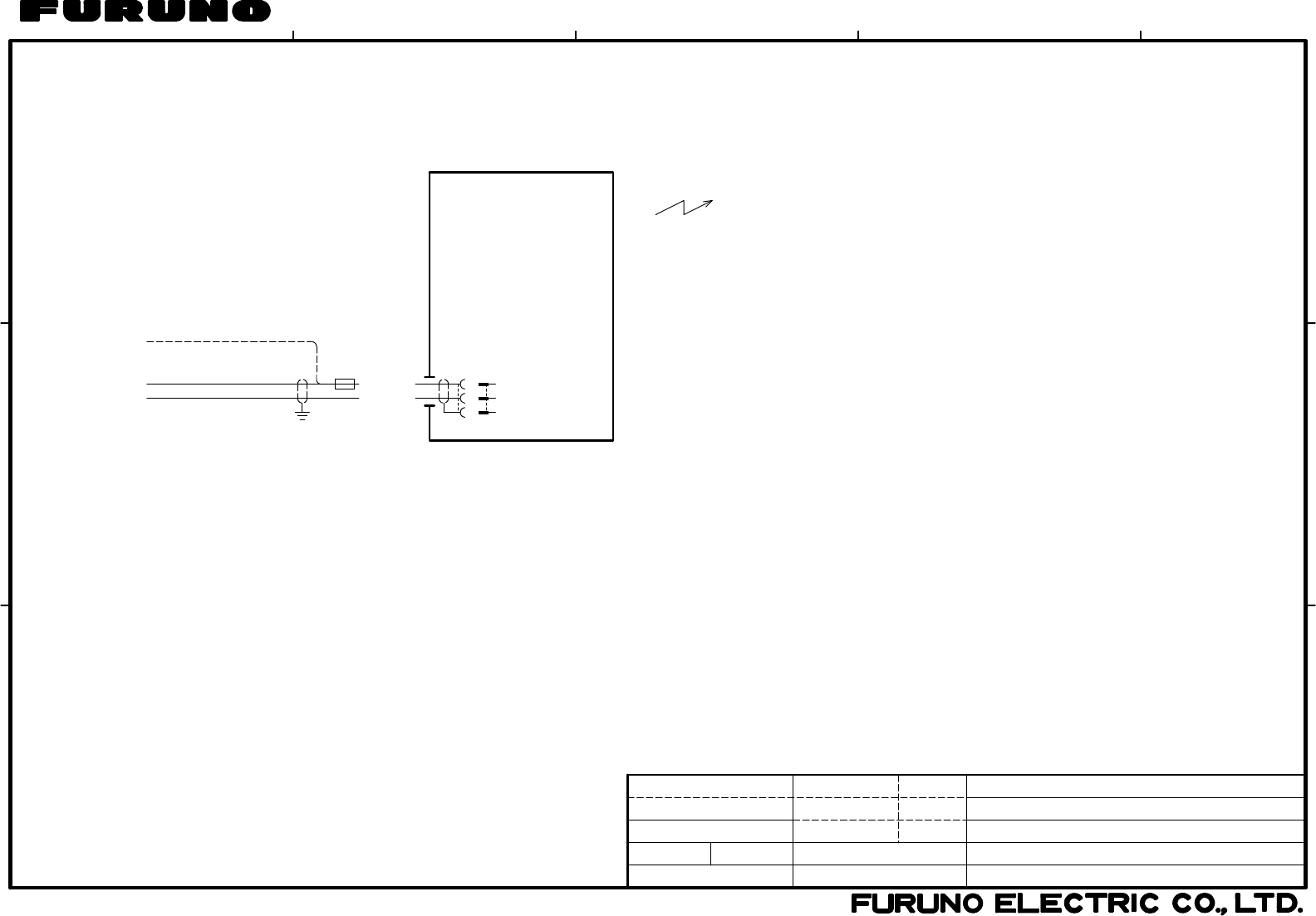
INTERCONNECTION DIAGRAM
相互結線図
DRS4W
レーダーセンサー
RADAR SENSOR
03-184-6011-0
H.MAKI
2.4 GHz, IEEE802.11b
1
2
3
SHIP'S MAIN-H
SHIP'S MAIN-C
GND
W802
アカ
アオ
RED
BLU
RSB-126-103
レーダーセンサー
RADAR SENSOR
(+)
(-)
12-24VDC FRU-3P-FF-15M,15m,φ10.3 5A
24VDC
*1: OPTION.
NOTE
注記
*1)オプション。
FRU-3P-FF-10M,10m,φ8.6(*1)
FRU-3P-FF-20M,20m,φ10.3(*1)
FRU-3P-FF-30M,30m,φ8.6(*1)
C3636-C01- B
24/Feb/2014
24/Feb/2014
25/Feb/2014 H.MAKI
TENTATIVE
S-1
FURUNO Worldwide Warranty for Pleasure Boats (Except North America)
This warranty is valid for products manufactured by Furuno
Electric Co. (hereafter FURUNO) and installed on a pleasure
boat. Any web based purchases that are imported into other
countries by anyone other than a FURUNO certified dealer may
not comply with local standards. FURUNO strongly recommends
against importing these products from international websites as
the imported product may not work correctly and may interfere
with other electronic devices. The imported product may also be
in breach of the local laws and mandated technical requirements.
Products imported into other countries as described previously
shall not be eligible for local warranty service.
For products purchased outside of your country please contact
the national distributor of Furuno products in the country where
purchased.
This warranty is in addition to the customer´s statutory legal
rights.
1. Terms and Conditions of Warranty
FURUNO guarantees that each new FURUNO product is the
result of quality materials and workmanship. The warranty is
valid for a period of 2 years (24 months) from the date of the
invoice, or the date of commissioning of the product by the
installing certified dealer.
2. FURUNO Standard Warranty
The FURUNO standard warranty covers spare parts and labour
costs associated with a warranty claim, provided that the product
is returned to a FURUNO national distributor by prepaid carrier.
The FURUNO standard warranty includes:
Repair at a FURUNO national distributor
All spare parts for the repair
Cost for economical shipment to customer
3. FURUNO Onboard Warranty
If the product was installed/commissioned and registered by a
certified FURUNO dealer, the customer has the right to the
onboard warranty.
The FURUNO onboard warranty includes
• Free shipping of the necessary parts
• Labour: Normal working hours only
• Travel time: Up to a maximum of two (2) hours
• Travel distance: Up to a maximum of one hundred
and sixty (160) KM by car for the complete journey
4. Warranty Registration
For the Standard Warranty - presentation of product with serial
number (8 digits serial number, 1234-5678) is sufficient.
Otherwise, the invoice with serial number, name and stamp of
the dealer and date of purchase is shown.
For the Onboard Warranty your FURUNO certified dealer will
take care of all registrations.
5. Warranty Claims
For the Standard Warranty - simply send the defective product
together with the invoice to a FURUNO national distributor.
For the Onboard Warranty – contact a FURUNO national
distributor or a certified dealer. Give the product´s serial number
and describe the problem as accurately as possible.
Warranty repairs carried out by companies/persons other than a
FURUNO national distributor or a certified dealer is not covered
by this warranty.
6. Warranty Limitations
When a claim is made, FURUNO has a right to choose whether
to repair the product or replace it.
The FURUNO warranty is only valid if the product was correctly
installed and used. Therefore, it is necessary for the customer to
comply with the instructions in the handbook. Problems which
result from not complying with the instruction manual are not
covered by the warranty.
FURUNO is not liable for any damage caused to the vessel by
using a FURUNO product.
The following are excluded from this warranty:
a. Second-hand product
b. Underwater unit such as transducer and hull unit
c. Routine maintenance, alignment and calibration
services.
d. Replacement of consumable parts such as fuses,
lamps, recording papers, drive belts, cables, protective
covers and batteries.
e. Magnetron and MIC with more than 1000 transmitting
hours or older than 12 months, whichever comes first.
f. Costs associated with the replacement of a transducer
(e.g. Crane, docking or diver etc.).
g. Sea trial, test and evaluation or other demonstrations.
h. Products repaired or altered by anyone other than the
FURUNO national distributor or an authorized dealer.
i. Products on which the serial number is altered,
defaced or removed.
j. Problems resulting from an accident, negligence,
misuse, improper installation, vandalism or water
penetration.
k. Damage resulting from a force majeure or other natural
catastrophe or calamity.
l. Damage from shipping or transit.
m. Software updates, except when deemed necessary
and warrantable by FURUNO.
n. Overtime, extra labour outside of normal hours such as
weekend/holiday, and travel costs above the 160 KM
allowance
o. Operator familiarization and orientation.
FURUNO Electric Company, March 1, 2011
TENTATIVE

FURUNO Warranty for North America
FURUNO U.S.A., Limited Warranty provides a twenty-four (24) months LABOR and twenty-four (24) months PARTS
warranty on products from the date of installation or purchase by the original owner. Products or components that are
represented as being waterproof are guaranteed to be waterproof only for, and within the limits, of the warranty
period stated above. The warranty start date may not exceed eighteen (18) months from the original date of purchase
by dealer from Furuno USA and applies to new equipment installed and operated in accordance with Furuno USA’s
published instructions.
Magnetrons and Microwave devices will be warranted for a period of 12 months from date of original equipment
installation.
Furuno U.S.A., Inc. warrants each new product to be of sound material and workmanship and through its authorized
dealer will exchange any parts proven to be defective in material or workmanship under normal use at no charge for a
period of 24 months from the date of installation or purchase.
Furuno U.S.A., Inc., through an authorized Furuno dealer will provide labor at no cost to replace defective parts,
exclusive of routine maintenance or normal adjustments, for a period of 24 months from installation date provided the
work is done by Furuno U.S.A., Inc. or an AUTHORIZED Furuno dealer during normal shop hours and within a radius
of 50 miles of the shop location.
A suitable proof of purchase showing date of purchase, or installation certification must be available to Furuno U.S.A.,
Inc., or its authorized dealer at the time of request for warranty service.
This warranty is valid for installation of products manufactured by Furuno Electric Co. (hereafter FURUNO). Any
purchases from brick and mortar or web-based resellers that are imported into other countries by anyone other than a
FURUNO certified dealer, agent or subsidiary may not comply with local standards. FURUNO strongly recommends
against importing these products from international websites or other resellers, as the imported product may not work
correctly and may interfere with other electronic devices. The imported product may also be in breach of the local
laws and mandated technical requirements. Products imported into other countries, as described previously, shall not
be eligible for local warranty service.
For products purchased outside of your country please contact the national distributor of Furuno products in the
country where purchased.
WARRANTY REGISTRATION AND INFORMATION
To register your product for warranty, as well as see the complete warranty guidelines and limitations, please visit
www.furunousa.com and click on “Support”. In order to expedite repairs, warranty service on Furuno equipment is
provided through its authorized dealer network. If this is not possible or practical, please contact Furuno U.S.A., Inc.
to arrange warranty service.
FURUNO U.S.A., INC.
Attention: Service Coordinator
4400 N.W. Pacific Rim Boulevard
Camas, WA 98607-9408
Telephone: (360) 834-9300
FAX: (360) 834-9400
Furuno U.S.A., Inc. is proud to supply you with the highest quality in Marine Electronics. We know you had several
choices when making your selection of equipment, and from everyone at Furuno we thank you. Furuno takes great
pride in customer service.
TENTATIVE