Furuno USA 9ZWRTR105 Transceiver for Radar model FAR-3210/3310 User Manual
Furuno USA Inc Transceiver for Radar model FAR-3210/3310
Users Manual

2-1
2. WIRING
2.1 Overview
Cabling considerations
To lessen the chance of picking up electrical interference, avoid where possible rout-
ing the antenna cable (power and LAN lines) near other onboard electrical equipment
(radars, TX radio antennas, etc.). Also avoid running the cable in parallel with power
cables. When crossing with other cable, the angle must be 90° to minimize the mag-
netic field coupling.
The antenna cable between the antenna and processor units is available in lengths of
15 m, 30 m, 40 m, and 50 m. Whatever length is used, it must be unbroken; namely,
no splicing allowed. Use the antenna cable as short as possible to minimize attenua-
tion of the signal.
The radar must be connected to an emergency power source, as required by SOLAS
II-1.
About network construction
About wiring
• Use the optional Switching Hub HUB-100 to connect the sensor networks. For the gate-
way networks, use the optional Intelligent Hub HUB-3000.
• Do not connect the ship’s LAN network to the optional HUBs. Also, commercial PCs
cannot be connected to the gateway network, other than for maintenance.
• To connect the FEA-2xx7, FMD-32xx, FAR-2xx7, FCR-2xx9 via LAN network, use the
INS network.
• Use the optional USB cable (type: OP24-32) to connect to the USB port on the control
unit.
• The length of the USB cable must be within 5 m to prevent equipment trouble.
• The length of LAN cables must be within 50 m.
• Use the Cat5e or Cat6 LAN cable for the network if available locally.
• If LAN cables are not available locally, use the optional LAN cables (FR-FTPC-CY for
sensor network, DTI-C5E350 VCV for gateway network).
• If extension or division of the DVI or RGB cables is necessary, use the dividers shown
below.
• DVI cable divider: DVI-12A (maker: IMAGENICS)
• RGB divider: CIF-12H, DD-106 or WBD-14F (maker: IMAGENICS)
• Make sure that the ground wires are connected between the ground terminals on each
equipment and the ship’s earth.
• If a UPS (user supply) is connected to this equip-
ment, be sure that the grounding lamp does not
light.
• The output from the UPS must be a sine wave, as
in the right figure.
50Hz
60Hz
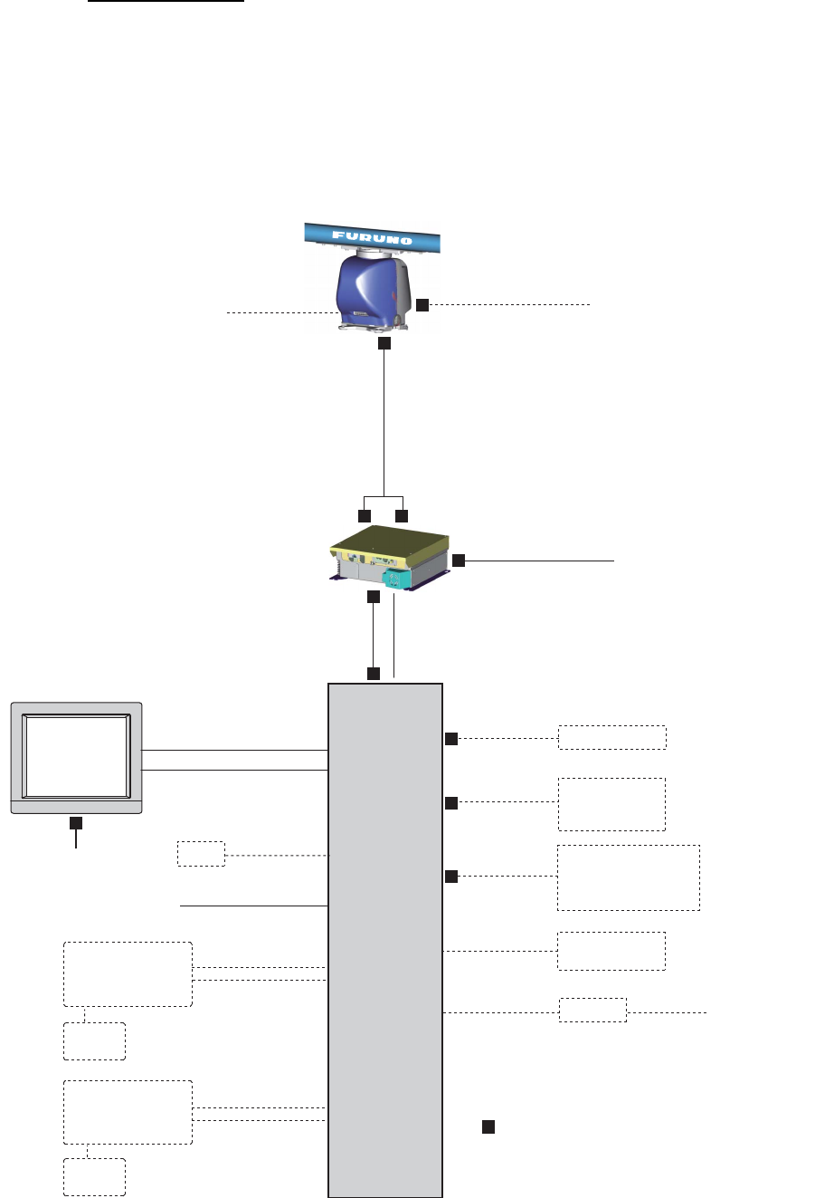
2. WIRING
2-2
Standard wiring
A Cat 5e LAN cable (RW-00135) connects between the antenna unit and the PSU.
The maximum length of the cabling between the Processor Unit and the antenna unit
is 80 m.
Retrofit (using antenna cable RW-4873/6896/9600) or foremast installation is also
possible, with the installation of a pair of LAN Signal Converters, one in the antenna
unit, the other in the PSU. See section 2.7.
100-230 VAC
RW-00135
15/30/40/50 m
DPYC-2.5
: Cable requires fabrication
DSUB9P-DSUB9P
5 m/10 m
Processor Unit
EC-3000
100-230 VAC
DVI-D/D SINGLE LINK
5 m/10 m
LAN: DTI-C5E 350 VCV
(10/20/30 m)
or
Cat 5e LAN cable
(local supply)
Power Supply Unit
PSU-014
Sensor Adapter
or HUB-100
Serial: TTYCS-1Q
FR-FTPC-CY
100-230 VAC
GYRO, AIS
TTYCS-4
x2
GPS, LOG, E/S,
WIND, ALARM,
NAVTEX, etc.
TTYCS-1Q
x5
5 m
(for USB)
30 m
x2
TTYCS-10 System fail, Power fail,
Normal close 1/2,
Normal open 1/2,
ACK IN
Monitor
Unit
DPYC-1.5
VDR RGB cable
IEC60320-C13-L5M
HUB-3000
5 m
(for USB)
30 m
Sub monitor
RW-00136
15/30/40/50 m
100-115/
100-230 VAC
USB
memory
Radar
Control Unit
RCU-025
Trackball
Control Unit
RCU-026
USB
memory
LAN Power
Antenna Unit
MU-190
(for FAR-3210/3220)
MU-231
(for FAR-3310/3320)
De-icer
100-115/220-230 VAC DPYCY-1.5
DTI-C5E 350 VCV
(10/20/30 m)
2. WIRING
2-3
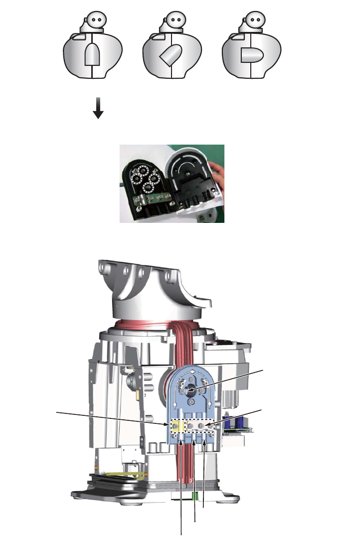
2.2 Antenna Unit
Three cables are connected to the antenna unit: antenna cable, cable for the sub mon-
itor (option) and power cable for the deicer (option). The procedure shows how to con-
nect all cables. Disregard the descriptions for the optional equipment if not applicable.
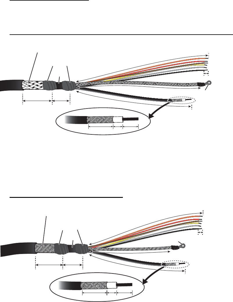
2.2.1 How to fabricate the cables
Antenna cable RW-00135
The end of the antenna cable RW-00135 which connects to the antenna unit is pre-
fabricated.
Antenna cable RW-9600/6895/4873 (for retrofit or foremast installation)
RW-9600 (foremast or retrofit):The white, red, and green wires are not used. Attach
a single crimp-on lug (FV5.5-S4(LF), yellow) locally to the wires. (These wires will be
connected together with the shield of the power line, in the next section.)
RW-6895/4873 (retrofit only): Fifteen wires are not used. Cut the wires and bind them
with vinyl tape. Do not connect the wires to ground.
Cable RW-00136 (for a sub monitor)
Sheath
Crimp-on lug
Shield
Shield
390
390
Sheath
Sheath
Vinyl tape
Coaxial
cable
Coaxial
cable
6
36 5
14 59
400
400
400
400
Armor (clamp with cable clamp.)
Armor (clamp with cable clamp.)
Crimp-on lug
Shield
Sheath
Sheath
Vinyl tape
Coaxial cable
Braided shield
6
14 59
36 5
3
9
0
3
9
0
330
330
4
5
0
4
5
0
2. WIRING
2-4
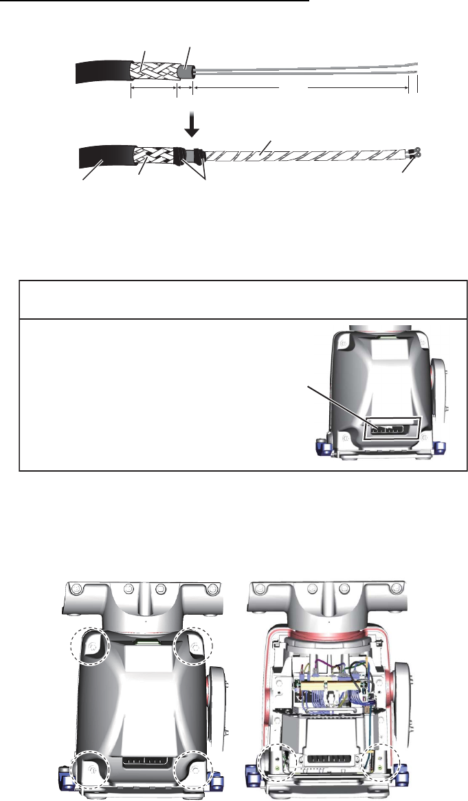
Cable DPYCY-1.5 (for the optional deicer)
2.2.2 How to connect the cables
Some parts or wiring have been omitted from the illustrations for clarity.
1. Unfasten four bolts from the rear cover to remove the rear cover. If the deicer is
already installed or will be installed, remove two bolts inside the antenna to enable
removal of the front cover. See Note 2.
Note 1: The cable for the performance monitor is connected between the rear
cover and the RF-TB Board in the antenna unit. Open the cover slowly to prevent
damage to the cable and connector.
Note 2: If the deicer is to be installed, spread open the right and left heater ele-
ments on the cover, then remove the front cover, being careful not to hit the ele-
ments on the radiator or chassis.
Note 3: If this a retrofit or foremast installation, a LAN Signal Converter is re-
quired, in both the antenna unit and the power supply unit. See section 2.7.
Armor
Sheath
Sheath
Crimp-on lug
(FV2-M4)
Wrap spiral tubing.
Lay armor in
cable clamp.
Sheath
Sheath Vinyl tape
6
10 900
36
NOTICE
If there is a chance of inclement
weather when the transceiver unit is
removed, cover the intake on both
covers with packing tape. Be sure to
remove the tape after completing the
installation.
Intake
2. WIRING
2-5
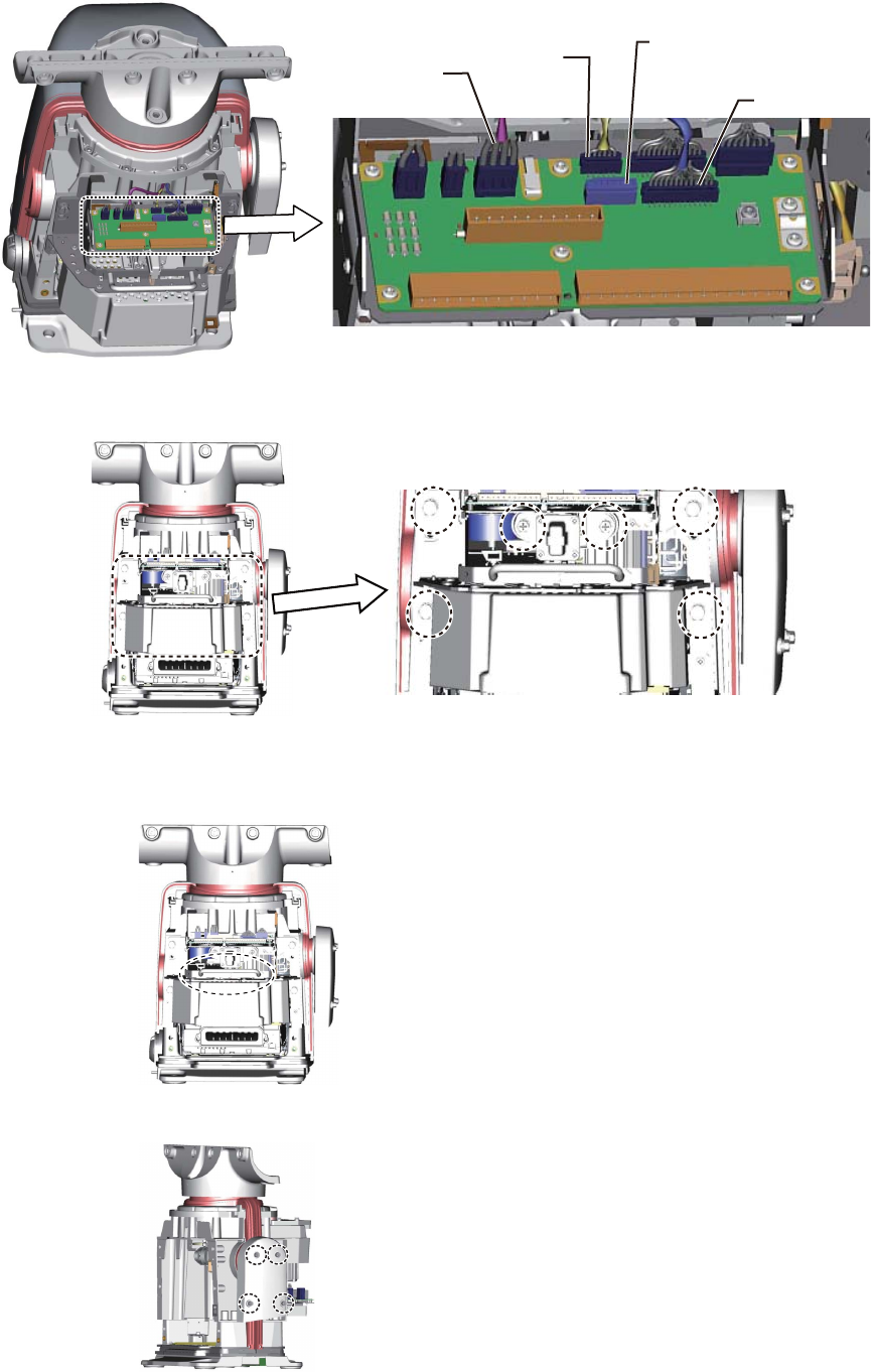
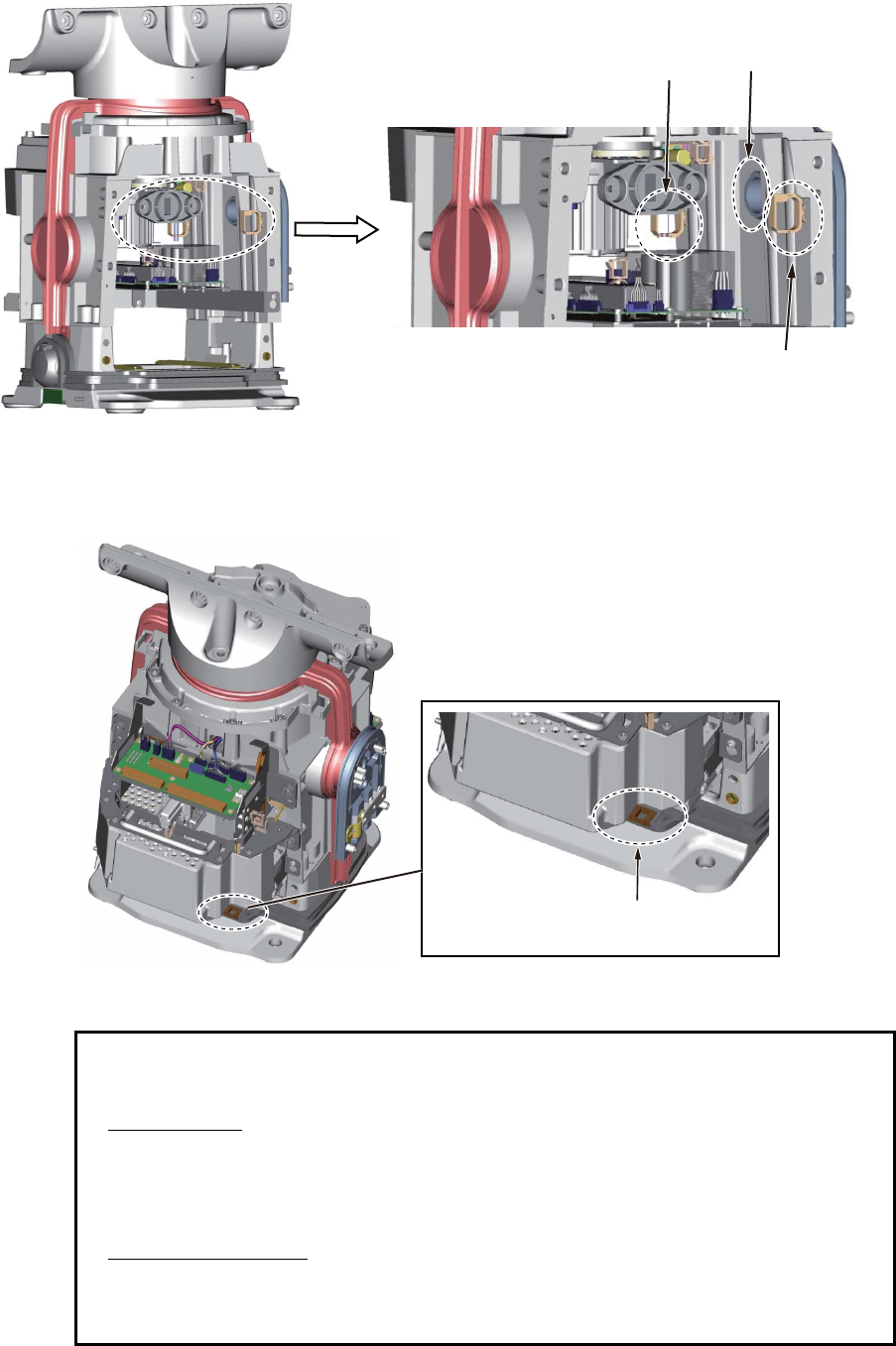
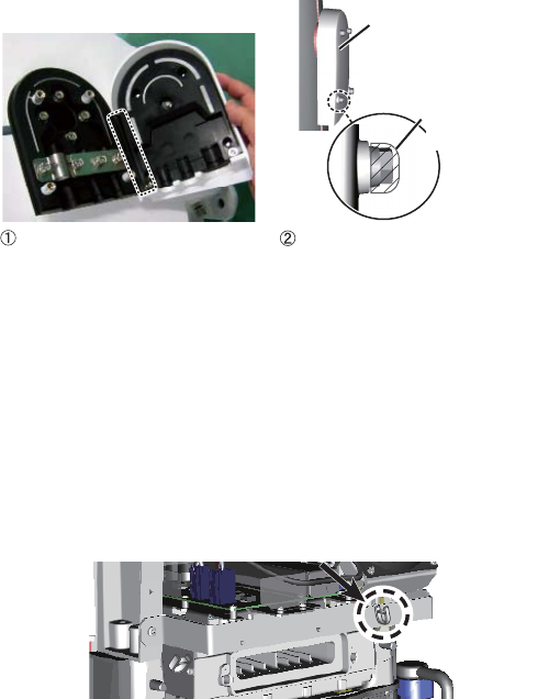
2. Disconnect the performance monitor connector (J807) and the motor drive con-
nectors (J803, J804 and J808) from the RF-TB Board.
3. Unfasten the six bolts circled in the figure below to enable removal of the trans-
ceiver unit.
4. Pull the handle on the transceiver unit to remove the unit. Lay the unit on its side
or on top of non-ferrous material, to prevent demagnetization of the magne-
tron.
5. Unfasten four screws to open the cable entrance cover.
J803
(motor)
J803
(motor)
J808
(motor)
J808
(motor)
J807
(performance monitor)
J804 (motor)
J804 (motor)
2. WIRING
2-6
Note: The orientation of the cable entrance assy. can be changed, in one of the
three orientations shown in the figure below. No other orientation is allowed, to
maintain watertight integrity. The default orientation is “deck”. To change the
entrance, unfasten the four screws circled in the figure below, then orient the ca-
ble entrance assy. in the required direction. Refasten the screws.
6. Unfasten the four screws fixing the cable clamp plates (2 pcs.).
Deck entrance Mid-stern entrance Stern entrance
BOW ►
TO CHANGE THE ORIENTATION:
Unfasten these screws to change the orientation of the cable entrance assy.
Antenna cable
Cable for deicer
Cable for sub monitor
Cable entrance
Cable clamp
plate for
antenna cable
Cable clamp plate
for cable for sub
monitor, deicer
2. WIRING
2-7
7. Pass the antenna cable through the cable entrance. If applicable, also pass the
cable for the sub monitor and the power cable for the deicer through the cable en-
trance. Pass the cables through their respective locking wire saddles.
8. Re-mount the transceiver unit then reconnect the connectors for the motor (J803,
J804 and J808). Pass the LAN cable through the locking wire saddle at the bottom
of the transceiver unit.
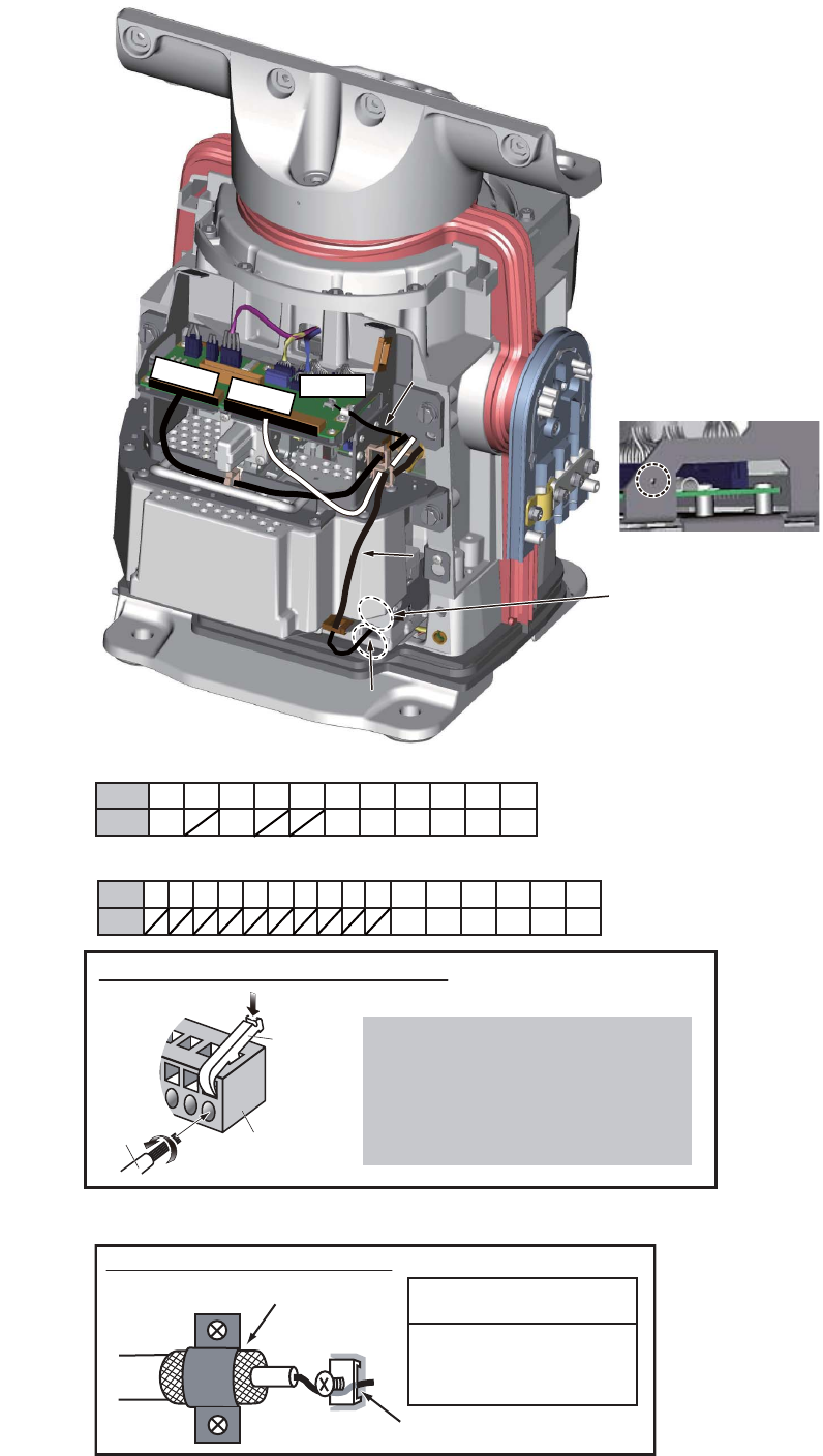
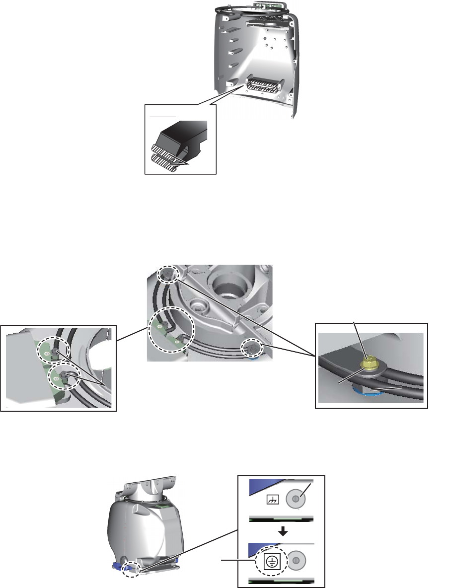
9. Connect the antenna cable and the cable for the sub monitor as shown below. See
the illustration on the next page for parts location.
• Attach appropriate WAGO connector (supplied) to both the antenna cable and the ca-
ble for the sub monitor. Connect the antenna cable and the cable for the sub monitor
to the RF-TB Board as shown below.
Antenna cable
Power line: TB801
LAN cable: J821
Shield of power line: Screw on fixing plate. See *1 in illustration on next page.
Shield of LAN cable: Screw above LAN cable port.
Cable for sub monitor
Signal line: TB803
Shield: Screw on fixing plate. See *2 in illustration on next page.
Coaxial cable: TB804
Locking wire saddle
for power cable for
deicer
Cable entrance
Locking wire saddle
for antenna cable,
cable for sub montior
Locking wire saddle
for LAN cable
2. WIRING
2-8
TB803
TB801
TB804
LAN cable
LAN cable
J821
J821
*1 Connect shield of
power line to screw on
plate.
*2 Connect shield of
cable for sub monitor to
screw on plate.
*1 Connect shield of
power line to screw on
plate.
*2 Connect shield of
cable for sub monitor to
screw on plate.
Coaxial cable
Coaxial cable
*1
*1
Connect shield of
LAN cable to
screw on chassis.
*2
*2
POWER: TB801 on RF-TB Board (03P9570)
Wire
How to connect wires to WAGO connector
Press downward.
Terminal
opener
WAGO
connector
Twist
<Procedure>
1. Twist the cores.
2. Press the terminal opener downward.
3. Insert the wire to hole.
4. Remove the terminal opener.
5. Pull the wire to confirm that it is secure.
SIGNAL: TB803 on RF-TB board
1 3 6789
11 12 13 14 15 16
245 10
BRN RED ORG YEL BLKWHT
Pin
Color
COAXIAL CABLE: TB804 on RF-TB board
How to fasten the coaxial cable
Fasten shield with clamp.
Fasten conductor with screw.
NOTICE
Do not use crimp-on lug, to
prevent contact resistance
from increasing.
1 3 6789 11
245 10
BRN RED ORG YEL GRN BLU
Pin
Color
PPL WHT
2. WIRING
2-9
Note 1: A terminal opener is provided on the RF-TB Board.
Note 2: For the antenna cable RW-9600, connect the crimp-on lug (that binds un-
used wires) together with the shield of the power line. See *1 on page 2-8 for the
location.
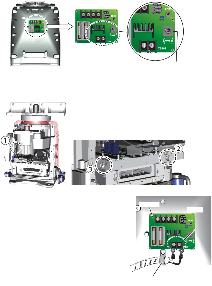
10. DE-ICER INSTALLATION. If the de-icer is not provided, go to step 12.
See also “X-band De-icer Kit Installation Instructions”, issued separately, for the
de-icer not fitted at the factory.
1) Set a locking wire saddle (supplied) at locations (2) and (3) shown below.
Pass the power cable through the locking wire saddles (1), (2) and (3) and pull
it to the front side.
2) Unfasten the cable band*. Pass the ca-
ble for the de-icer through the band
then fasten the band. Connect the ca-
ble to TB901 on the DE-ICER board,
using the crimp-on lugs supplied.
* For the DE-ICER installation kit, un-
fasten the cable band on the cover
supplied. (The original cover can be
discarded.)
3) Set the Voltage Selection switch ac-
cording to the power source for the de-
icer; 115 V or 230 V.
4) Apply power to the deicer then press
the [TEST] button about ten seconds.
Check that the heater gets hot.
Front cover, inside view
DEICER Board
(03P9573)
DEICER Board (03P9573)
Voltage Selection switch
[TEST] button
[TEST] button
TB901
TB901
03P9573 TB901
Cable band
Cable band
2. WIRING
2-10
5) Coat the gasket (all brims) of the intake with the supplied oil compound. Be
sure to coat the gasket completely.
6) Set the front cover to the antenna unit. Take care not to hit the heater ele-
ments on the chassis or radiator.
7) Coat two M5 screws (supplied) with marine sealant then use them to fasten
the base of the heater. Fasten the installation materials shown below to each
of the cover bolts.
8) Attach the supplied earth label over the earth label currently attached near the
grounding terminal.
11. Position the cables so their armors lie beneath their respective cable clamp plates
in the cable entrance. Fasten the plates.
Hatch: Oil compound
Brim
Brim
Intake
Intake
M5 screw coated with
marine sealant
M5 screw coated with
marine sealant
Fixing
shaft
Fixing
shaft
Cover bolt
Cover bolt
M5 screw coated with
marine sealant
M5 screw coated with
marine sealant
Grounding
terminal
Grounding
terminal
Earth
label
2. WIRING
2-11
12. Close the cable entrance cover as shown in the figure below.
13. Connect the performance monitor connector (J807) to the rear cover.
14. Check that the gasket on the front and rear covers is seated properly, then
close the covers. The torque for the fixing bolts is 10.0 N•m.
Note: If it is necessary to open the front cover after installing the de-icer kit, remove
the power cable from the locking wire saddle shown in the right figure then detach the
cover slowly to prevent damage to the heater element.
Cable entrance
cover
Marine
sealant
Close cover then coat screw
heads with marine sealant.
Coat this part of gasket
with marine sealant.
Remove cable from locking wire
saddle to open front cover.
Remove cable from locking wire
saddle to open front cover.
2. WIRING
2-12
2.3 Processor Unit
Note: The interface ports approved for interconnecting navigation equipment are
shown in the figure below. For details, see section 2.3.3 "How to select the serial input/
output format".
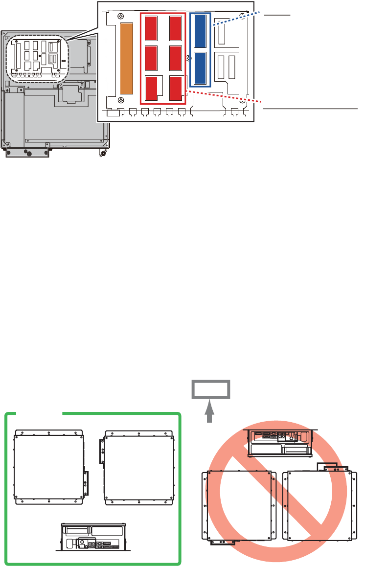
2.3.1 How to connect cables to terminals in the processor unit
Use screws (M3×6, supplied) to attach the wiring plate 1 and wiring plate 2 to the pro-
cessor unit. Connect the cables shown below to the connectors at the front of the pro-
cessor unit. Bind cables to the appropriate fixing metal with the cable ties (supplied).
For the cables from the monitor unit (type: DVI-D/D SLINK5M/10M (MU-190 only),
DSUB9P-X2-L5/10M) and ground wire, connect them to the processor unit directly
(without fixing to a wiring plate). Tighten the fixing screws on these connectors to pre-
vent disconnection from the processor unit.
Note: Connect the cables so that they do not interfere with the opening or closing of
the DVD tray.
J5
J5J5
J11
J11J11
J4
J4J4
J3
J3J3
J8
J8J8
J9
J9J9
J10
J10J10
J6
J6J6
J7
J7J7
J12
J12J12
J13
J13J13
J14
J14J14
J3, J4
For IEC 61162-2 or
IEC 61162-1
J5, J6, J7, J8, J9, J10
For IEC 61162-1
Top view of EC-3000
OK
UP
2. WIRING
2-13
Cables connected at wiring plate 1
• USB cables from the control units
• Printer cable
• LAN cable (type: DTI-C5E350 VCV) from the HUB-3000
• LAN cable (type: FR-FTPC-CY) from the HUB-100/MC-3000S
Cables connected at the wiring plate 2
• Power cable (Type: IEC60320-C13-L5M)
• LAN cable to the LAN3 port
MU-190/231
(DVI1: DVI-D/D S-LINK cable,
COM1: DSUB9P-X2-L cable)
COM1
VDR
(DVI3: BNCX5-L2000)
DVI3
USB1
RCU-025/026
(TS-20-071-1 cable)
USB2/3
Optional control unit
RCU-024/025/026
(TS-20-071-1 cable)
HUB-3000
(DTI-C5E350 VCV
cable)
LAN1
LAN2
HUB-100/MC-3000S
(FR-FTPC-CY cable,
within 50m)
DVI1
COM2
Cable clamp
(See the next page.)
Ground wire
(IV-2sq.,
local supply)
Power cable
(IEC60320-C13-
L5M cable)
USB4
For USB printer
LAN3
DVI2
MU-190/231
(COM2: DSUB9P-
X2-L cable
DVI2: DVI-D/D
S-LINK cable)
MOD-Z072-005+
2. WIRING
2-14
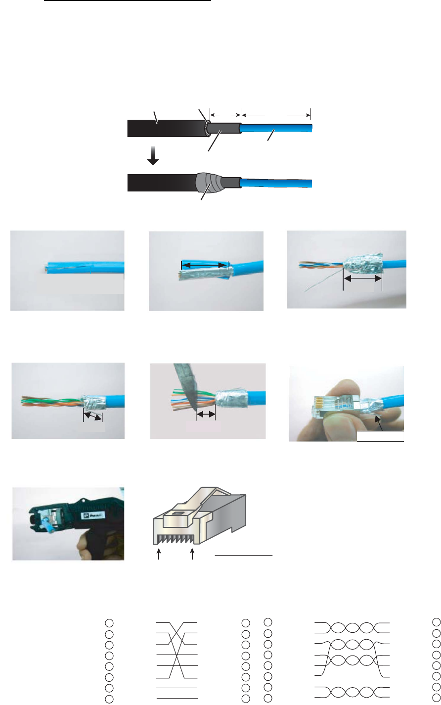
How to fabricate the LAN cable
Fabricate the LAN cable (FR-FTPC-CY, DTI-C5E350 VCV), as shown below. (Wrap
both edges of the armor with vinyl tape.) Make sure the shield of the cable contacts
the shell of the modular plug.
Note: For a locally supplied LAN cable, expose the armor and clamp the armor with
the cable clamp.
Wrap vinyl tape. (width: 20 mm)
Cable jacket Armor
Outer vinyl sheath
Inner vinyl sheath
55
30
Using special crimping tool
MPT5-8 (PANDUIT CORP.),
crimp the modular plug.
Finally check the plug visually.
1 WHT/GRN
2 GRN
3 WHT/ORG
4 BLU
5 WHT/BLE
6 ORG
7 WHT/BRN
8 BRN
WHT/ORG 1
ORG 2
WHT/GRN 3
BLU 4
WHT/BLE 5
GRN 6
WHT/BRN 7
BRN 8
1 WHT/ORG
2 ORG
3 WHT/GRN
4 BLU
5 WHT/BLE
6 GRN
7 WHT/BRN
8 BRN
WHT/ORG 1
ORG 2
WHT/GRN 3
BLU 4
WHT/BLE 5
GRN 6
WHT/BRN 7
BRN 8
Expose inner vinyl sheath.
[Crossover cable] [Straight cable]
Remove the outer sheath by
approx 25 mm. Be careful
not to damage inner shield
and cores.
Fold back the shield, wrap it
onto the outer sheath and
cut it, leaving 9 mm.
12
3
25 mm
approx. 9 mm
456
approx. 9 mm approx. 11 mm
Drain wire
Fold back drain wire and
cut it, leaving 9 mm.
Straighten and flatten the
core in order and cut them,
leaving 11 mm.
Insert the cable into the modular
plug so that the folded part of
the shield enters the modular
plug. The drain wire must be on
the tab side of the jack.
7
18
Modular plug
2. WIRING
2-15
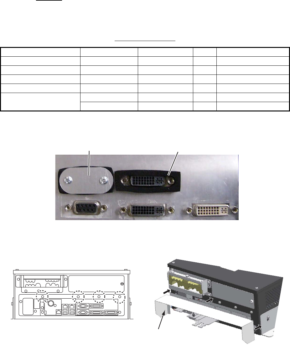
IPX2 kit
The optional IPX2 kit (Type: OP24-23, Code No.: 001-171-780) protects the connec-
tors shown below to waterproofing standard IPX2.
Contents of IPX2 kit
1. Set the connector gasket to the unused connector not used.
2. Fasten two binding screws to fix the connector gasket.
3. Peel the paper from the double-sided tape on the rainproof cover, then attach the
cover to the position shown below by using four screws pre-attached to the pro-
cessor unit.
Name Type Code No. Qty Remarks
Binding Screw #4-40UNCX3/16 000-176-619-10 10
Connector Gasket 1 24-014-0107 100-367-730-10 2 For D-sub connectors
Connector Gasket 2 24-014-0108 100-367-741-10 3 For DVI connectors
Rainproof Cover 24-014-0109 100-372-202-10 1
Gasket Clamping Plate 24-014-0114 100-372-210-10 2 For D-sub connectors
24-014-0115 100-372-220-10 3 For DVI connectors
Connector gasket
Gasket clamping plate
Screws to fix the rainproof cover
Rainproof cover
Processor unit
Processor unit
2. WIRING
2-16
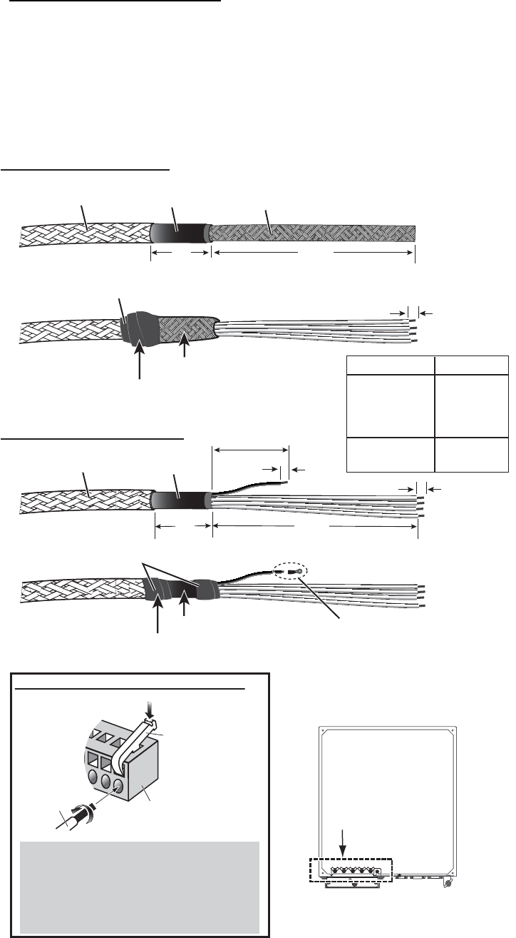
2.3.2 How to connect cables inside the processor unit
How to fabricate the cables
Fabricate the JIS cables (see the Appendix for equivalent cables if not available local-
ly) as shown below. Connect the cables to the WAGO connectors on the I/O Board
(24P0124) inside the processor unit.
For locations of cables and cores, see the sticker on the reverse side of the top cover.
(All dimensions in millimeters)
Shield
6
5
100
*
30
Armor
Sheath
L
Fabrication of TTYCS series
Vinyl tape (Width: 20) After exposing cores, wind shield
around the armor.
Clamp here by cable clamp.
Length of “L”
TTYCS-4,
TTYCSLA-4,
TTYCS-1Q,
TTYCSLA-1Q
TTYCS-10,
TTYCSLA-10
400
380
Cable type (JIS)
Fabrication of TTYCSLA series
Pass the heat shrinkable tube
(local supply) onto the drain wire,
then attach the crimp-on lug
(preattached to the earth clamp
on the processor unit) to it.
Sheath
Armor
Vinyl tape (Width: 20)
Drain wire
Crimp-on lug
Processor unit, cover removed
Crimp-on lugs for
drain wires
30 L
6
How to connect wires to WAGO connector
Press downward.
Terminal opener
WAGO connector
Wire
Twist
<Procedure>
1. Twist the cores.
2. Press the terminal opener downward.
3. Insert the wire to hole.
4. Remove the terminal opener.
5. Pull the wire to confirm that it is secure.
Cable tie (supplied)
Clamp here by cable clamp.
Cable tie (supplied)
2. WIRING
2-17
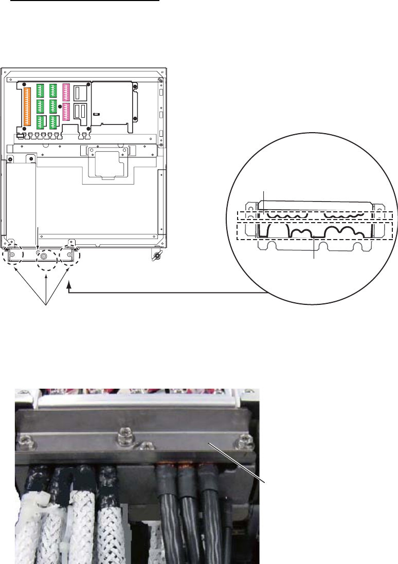
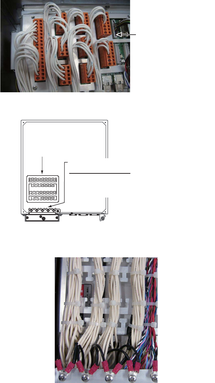
How to connect the cables
1. Unfasten four screws (M4×8) to remove the top cover from the processor unit.
2. Unfasten the three bolts circled below to remove the upper plate of the cable
clamp.
Processor unit, top view
3. Pass the cables through the clamp holes, then fasten the bolts removed at step 2
to fix the cables.
Unfasten these three bolts to remove the upper plate.
Unfasten this bolt to use
the lower clamp holes.
Unfasten this bolt to use
the lower clamp holes.
Clamp holes
(upper)
Clamp holes
(lower)
J4
J4
J3
J3
J8
J8
J9
J9
J10
J10
J5
J5
J6
J6
J7
J7
J11
J11
J12
J12
J13
J13
J14
J14
Lay shields of cables
under this clamp then
tighten the clamp.
2. WIRING
2-18
4. Connect the WAGO connectors to the I/O Board, referring to the interconnection
diagram.
5. Bind the cables to the fixing metal in the processor unit with the cable ties (sup-
plied).
6. For the drain wire of the TTYCSLA series cable, attach shrink tubing (local supply)
to drain wire, fasten a crimp-on lug (pre-attached at location shown below) to drain
wire then fasten the wire with a screw.
Example of wiring inside the processor unit
J12 (main control unit)
For J13 and J14 (sub
control units), see the figure
at step 2 in this procedure.
Fixing metal
Screws for drain wires
of TTYCSLA cables
Pass drain wire through shrink tubing (local
supply), attach a crimp-on lug (preattached)
to drain wire and fasten wire here.
2. WIRING
2-19
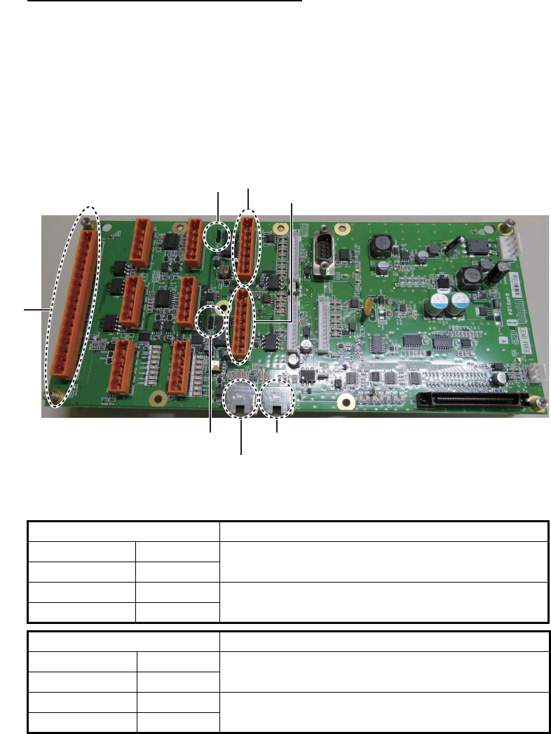
2.3.3 How to select the serial input/output format
How to set the termination resistors
Use the jumper blocks JP1 and JP2 on the I/O Board (24P0124) to set the termination
resistor J3 and J4 ON or OFF. The default setting is ON.
• When setting the starting/ending terminal for the multipoint connection, or multipoint
is not connected (CH1 or CH2): termination resistor ON
• When not setting the starting/ending terminal for the multipoint connection (CH1 or
CH2): termination resistor OFF
Processor unit, I/O Board (24P0124)
Jumper block J1 Connector J3
1-2 SHORT Termination resistor: ON (default setting)
2-3 OPEN
1-2 OPEN Termination connector: OFF
2-3 SHORT
Jumper block J2 Connector J4
1-2 SHORT Termination resistor: ON (default setting)
2-3 OPEN
1-2 OPEN Termination connector: OFF
2-3 SHORT
J4
J11
JP1 J3
JP2
J15 (to LAN port on EC-3000)
J16 (to LAN port on PSU)

2. WIRING
2-20
How to select the serial input/output format
Use the connectors J3 and J4 to set the input/output format for serial CH1/CH2, from
IEC-61162-1 or IEC-61162-2. For connectors J5 to J10, use the TTYCS-1Q or TTYC-
SLA-1Q cable.
Connector J3
Connector J4
Connector J5
Pin# Signal In/Out Description IEC61162-2 IEC61162-1
1 TD1-A Out Serial CH1, output
IEC61162-1/2
TTYCS(LA)-4 TTYCS(LA)-4
2 TD1-B Out Serial CH1, output
IEC61162-1/2
3 RD1-A In Serial CH1, input
IEC61162-2
No connection
4 RD1-B In Serial CH1, input
IEC61162-2
5 ISOGND1 - Isolation GND (CH1)
6 RD1-H In Serial CH1, input
IEC61162-1
No connection TTYCS(LA)-4
7 RD1-C In Serial CH1, input
IEC61162-1
Pin# Signal In/Out Description IEC61162-2 IEC61162-1
1 TD2-A Out Serial CH2, output
IEC61162-1/2
TTYCS(LA)-4 TTYCS(LA)-4
2 TD2-B Out Serial CH2, output
IEC61162-1/2
3 RD2-A In Serial CH2, input
IEC61162-2
No connection
4 RD2-B In Serial CH2, input
IEC61162-2
5 ISOGND2 - Isolation GND (CH2)
6 RD2-H In Serial CH2, input
IEC61162-1
No connection TTYCS(LA)-4
7 RD2-C In Serial CH2, input
IEC61162-1
Pin# Signal In/Out Description Remarks
1 TD3-A Out Serial CH3, output IEC61162-1 Use TTYCS(LA)-1Q,
IEC61162-1 only
2 TD3-B Out Serial CH3, output IEC61162-1
3 RD3-H In Serial CH3, input IEC61162-1
4 RD3-C In Serial CH3, input IEC61162-1
5 GND - GND
2. WIRING
2-21
Connector J6
Connector J7
Connector J8
Connector J9
Connector J10
Pin# Signal In/Out Description Remarks
1 TD4-A Out Serial CH4, output IEC61162-1 Use TTYCS(LA)-1Q,
IEC 61162-1 only
2 TD4-B Out Serial CH4, output IEC61162-1
3 RD4-H In Serial CH4, input IEC61162-1
4 RD4-C In Serial CH4, input IEC61162-1
5 GND - GND
Pin# Signal In/Out Description Remarks
1 TD5-A Out Serial CH5, output IEC61162-1 Use TTYCS(LA)-1Q,
IEC 61162-1 only
2 TD5-B Out Serial CH5, output IEC61162-1
3 RD5-H In Serial CH5, input IEC61162-1
4 RD5-C In Serial CH5, input IEC61162-1
5 GND - GND
Pin# Signal In/Out Description Remarks
1 TD6-A Out Serial CH6, output IEC61162-1 Use TTYCS(LA)-1Q,
IEC 61162-1 only
2 TD6-B Out Serial CH6, output IEC61162-1
3 RD6-H In Serial CH6, input IEC61162-1
4 RD6-C In Serial CH6, input IEC61162-1
5GND - GND
Pin# Signal In/Out Description Remarks
1 TD7-A Out Serial CH7, output IEC61162-1 Use TTYCS(LA)-1Q,
IEC61162-1 only
2 TD7-B Out Serial CH7, output IEC61162-1
3 RD7-H In Serial CH7, input IEC61162-1
4 RD7-C In Serial CH7, input IEC61162-1
5GND - GND
Pin# Signal In/Out Description Remarks
1 TD8-A Out Serial CH8, output IEC61162-1 Use TTYCS(LA)-1Q,
IEC61162-1 only,
For PSU
2 TD8-B Out Serial CH8, output IEC61162-1
3 RD8-H In Serial CH8, input IEC61162-1
4 RD8-C In Serial CH8, input IEC61162-1
5GND - GND
2. WIRING
2-22
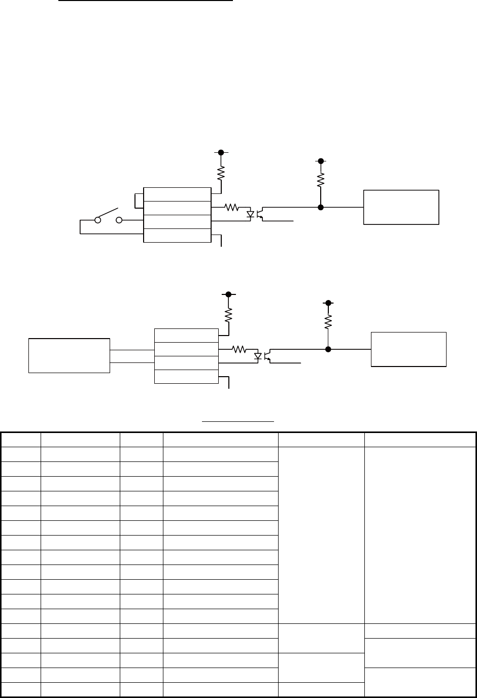
How to set contact input/output
The connector J11 can be used for the connection of contact input or voltage input.
Refer to the figures shown below to make the wiring which complies with the input
specification.
Note: The input must not exceed the range of the input voltage, to prevent malfunc-
tion.
-Setting for voltage input: 21.6V to 31.2V
-Setting for contact input: Voltage cannot be input (contact signal only).
• (Setting for contact input)
• (Setting for voltage input)
Connector J11
Note: NC1/2 and NO1/2 are output with a fixed value.
Pin # Signal name In/Out Description Contact input Voltage input
1 SYS_FAIL-A Out System fail output TTYCS(LA)-10 TTYCS(LA)-10
2 SYS_FAIL-B Out System fail output
3 PWR_FAIL-A Out Power fail output
4 PWR_FAIL-B Out Power fail output
5 NC1-A Out Alarm output (NC1)
6 NC1-B Out Alarm output (NC1)
7 NC2-A Out Alarm output (NC2)
8 NC2-B Out Alarm output (NC2)
9 NO1-A Out Alarm output (NO1)
10 NO1-B Out Alarm output (NO1)
11 NO2-A Out Alarm output (NO2)
12 NO2-B Out Alarm output (NO2)
13 DC12V_OUT Out ACK input #13-#14: short No connection
14 DIGI_IN1 In ACK input TTYCS(LA)-10
15 DIGI_RTN1 Out ACK input TTYCS(LA)-10
16 GND (DC12V) In ACK input No connection
17 GND - GND NO connection
GND
5V
12V
GND
470Ω/ 0.5W
2.2kΩ / 1W
Contact input
DC12V_OUT
DIGI_INx
DIGI_RTNx
GND(DC12V)
Photocoupler circuit
Resistor
Use NH connector
and AWG24 wire.
Processor unit
(I/O board)
DC12V_OUT
DIGI_INx
DIGI_RTNx
GND(DC12V)
GND
5V
DC voltage input
(21.6V to 31.2V)
+
-
12V
GND
470Ω/ 0.5W
2.2kΩ / 1W
Photocoupler circuit
Resistor
Processor unit
(I/O board)