Furuno USA 9ZWRTR111 Transceiver for Radar model FAR-3230S-SSD/3330SSSD User Manual
Furuno USA Inc Transceiver for Radar model FAR-3230S-SSD/3330SSSD
Users Manual

www.furuno.com
All brand and product names are trademarks, registered trademarks or service marks of their respective holders.
Installation Manual
CHART RADAR
Model
FAR-3230S-SSD(-BB)/FAR-3330S-SS
D
(Product name: MARINE RADAR)
SAFETY INSTRUCTIONS ................................................................................................ i
SYSTEM CONFIGURATION .......................................................................................... iii
EQUIPMENT LISTS........................................................................................................ vi
1. INSTALLATION.......................................................................................................1-1
1.1 Antenna Unit ......................................................................................................................1-1
1.2 Monitor Unit........................................................................................................................1-8
1.3 Radar Control Unit, Trackball Control Unit.........................................................................1-8
1.4 Power Supply Unit (PSU-016/PSU-018)..........................................................................1-11
1.5 Processor Unit .................................................................................................................1-12
1.6 Sensor Adapter MC-3000S/3010A/3020D/3030D (option)..............................................1-13
1.7 Intelligent Hub HUB-3000 (option)...................................................................................1-14
1.8 Switching Hub HUB-100 (option).....................................................................................1-16
2. WIRING....................................................................................................................2-1
2.1 Overview ............................................................................................................................2-1
2.2 Antenna Unit ......................................................................................................................2-3
2.3 Processor Unit .................................................................................................................2-10
2.4 Power Supply Unit ...........................................................................................................2-21
2.5 Monitor Unit......................................................................................................................2-25
2.6 Sensor Adapters (option).................................................................................................2-26
2.7 LAN Signal Converter Kit (option)....................................................................................2-43
2.8 Intelligent Hub HUB-3000 (option)...................................................................................2-47
2.9 How to Extend the Control Unit Cable (option) ................................................................2-48
3. SETTINGS AND ADJUSTMENTS ..........................................................................3-1
3.1 How to Access the Radar Installation Menu ......................................................................3-1
3.2 How to Align the Heading ..................................................................................................3-1
3.3 How to Adjust the Sweep Timing.......................................................................................3-2
3.4 How to Suppress Main Bang .............................................................................................3-3
3.5 Dual Radar Display............................................................................................................3-3
3.6 Other Settings....................................................................................................................3-6
4. INPUT/OUTPUT DATA............................................................................................4-1
4.1 Processor Unit ...................................................................................................................4-1
4.2 IEC 61162 Sentences........................................................................................................4-2
APPENDIX 1 JIS CABLE GUIDE .............................................................................AP-1
APPENDIX 2 ROD TERMINALS ..............................................................................AP-2
APPENDIX 3 DIGITAL INTERFACE ........................................................................AP-7
PACKING LISTS ......................................................................................................... A-1
OUTLINE DRAWINGS ................................................................................................ D-1
INTERCONNECTION DIAGRAM ................................................................................ S-1

The paper used in this manual
is elemental chlorine free.
・FURUNO Authorized Distributor/Dealer
9-52 Ashihara-cho,
Nishinomiya, 662-8580, JAPAN
A
:
APR
2014
.
Printed in Japan
All rights reserved.
C
:
OCT
.
15, 2014
Pub. No.
IME-36190-C
(
AKMU
)
FAR-3230S-SSD
0 0 0 1 7 8 0 3 5 1 2
i
SAFETY INSTRUCTIONS
The operator and installer must read the applicable safety instructions before attempting to
install or operate the equipment.
DANGER
Indicates a potentially hazardous situation which, if not avoided,
will result in death or serious injury.
Indicates a potentially hazardous situation which, if not avoided,
could result in death or serious injury.
CAUTION
Indicates a potentially hazardous situation which, if not avoided,
can result in minor or moderate injury.
Warning, Caution Prohibitive Action Mandatory Action
DANGER
Wear a safety belt and hard hat when working on the antenna unit.
Serious injury or death can result if someone falls from the radar antenna
mast.
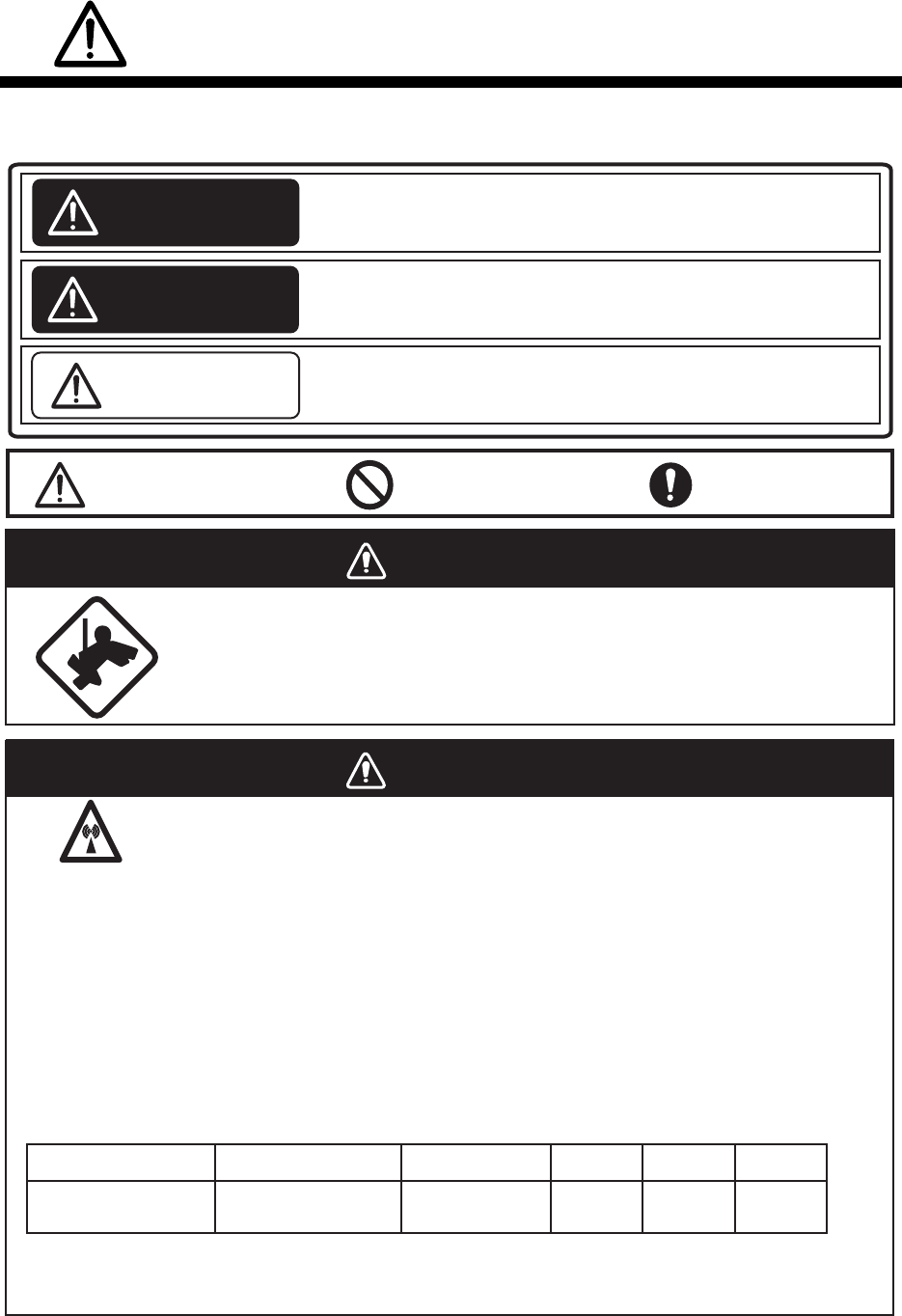
WARNING
Radio Frequency Radiation Hazard
The radar antenna emits electromagnetic radio frequency (RF) energy which can be
harmful, particularly to your eyes. Never look directly into the antenna aperture from a
close distance while the radar ius in operation or eexpose yourself to the transmitting
antenna at a close distance. Distances at which RF radiation level of 100, 50 and 10
W/m
2
are given in the table below.
Note: If the antenna unit is installed at a close distance in front of the wheel house,
your administration may require halt of transmission within a certain sector of
antenna revolution. This is possible. Ask your FURUNO representive or dealer to
provide this feature.
FAR-3230S-SSD(-BB)
FAR-3330S-SSD
RTR-111 (S-250W) SN36CF (12 ft)
WARNING
Transceiver
Model Antenna 100 W/m2
N/A
50 W/m210 W/m2
N/A 1.0 m
SAFETY INSTRUCTIONS
ii
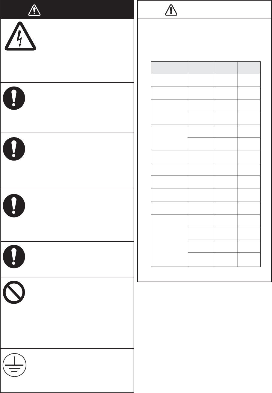
CAUTION
Observe the following compass safe
distances to prevent deviation of a
magnetic compass:
Note: For more information, please refer to
IMO SN/Circ.271 “Guidelines for the
installation of shipborne radar equip-
ment.”
Standard
compass
Antenna Unit
Processor Unit
Monitor Unit
Power Supply
Unit
ECDIS Control
Unit
Radar Control
Unit
Trackball Control
Unit
Switching Hub
Intelligent HUB
Sensor Adapter
Steering
compass
Type
EC-3000
MU-190
MU-231
PSU-016
RCU-024
RCU-025
RCU-026
(HUB-100)
HUB-3000
MD-3000S
MD-3010A
MD-3020D
MD-3030D
1.90 m 1.20 m
2.40 m
1.65 m
0.85 m
1.90 m
0.30 m
0.30 m
0.30 m
1.00 m
1.20 m
2.05 m
0.75 m
1.05 m
0.90 m
1.55 m
1.05 m
0.55 m
1.20 m
0.30 m
0.30 m
0.30 m
0.60 m
0.75 m
1.35 m
0.50 m
0.70 m
0.60 m
RSB-133
PSU-018
1.80 m 1.15 m
Do not open the equipment
unless totally familiar with
electrical circuits and service
manual.
Only qualified personnel are
allowed to work inside the
equipment.
WARNING
ELECTRICAL
SHOCK
HAZARD
Construct a suitable service
platform from which to install the
antenna unit.
Serious injury or death can result if
someone falls from the radar antenna
mast.
Turn off the power at the mains
switchboard before beginning the
installation.
Fire, electrical shock or serious injury
can result if the power is left on or is
applied while the equipment is being
installed.
Be sure that the power supply is
compatible with the voltage rating
of the equipment.
Connection of an incorrect power
supply can cause fire or damage the
equipment.
Use only the specified power
cable.
Fire or damage to the equipment can
result if a different cable is used.
Do not install the monitor unit,
processor unit, power supply unit
(PSU), or control unit in a dusty
environment, or one where the
units may get wet from rain or
water splash.
Dust or water in the units can result in
fire, electrical shock, or damage to
the equipment.
Attach protective earth securely to
the ship's body.
The protective earth (grounding) is
required for the AC power supply to
prevent electrical shock.
iii
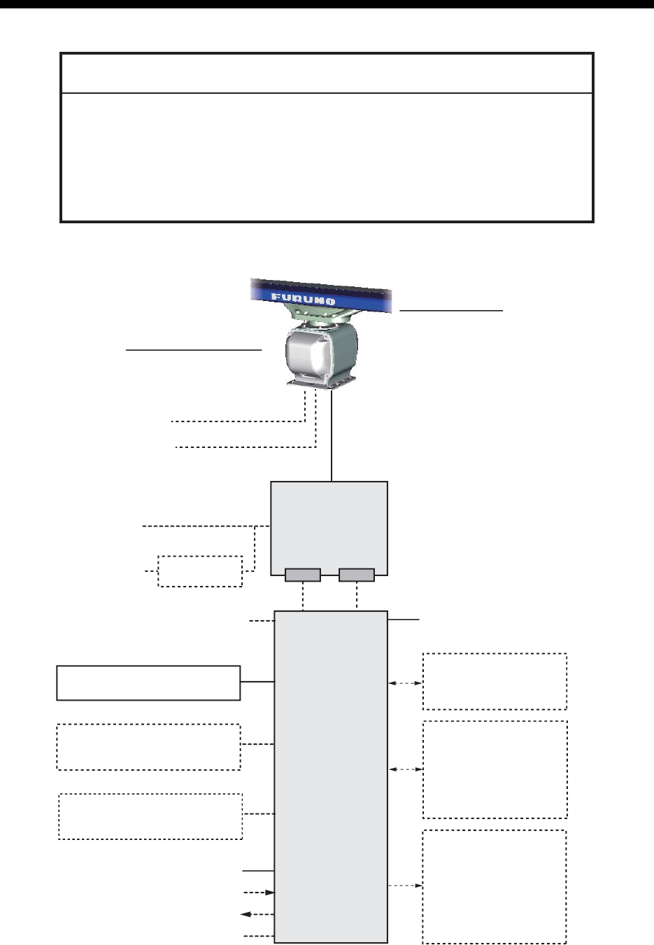
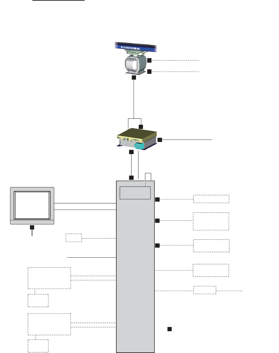
SYSTEM CONFIGURATION
Basic configuration is shown with solid line.
*: See the notes on page iv.
NOTICE
The radar(s) must be interconnected to the following type approved sensors:
Gyrocompass meeting the requirements of the IMO resolution A.424(XI).
EPFS meeting the requirements of the IMO resolution MSC.112(73).
SDME meeting the requirements of IMO resolution MSC.96(72).
The radar may be interconnected via HUB-3000 to other FURUNO processing
units having approved LAN ports.
100-115/220-230 VAC
1ø, 50-60 Hz
PSU-016 or PSU-018
POWER SUPPLY
UNIT
EC-3000
PROCESSOR
UNIT
Serial 1, 2
IEC 61162-2
(Gyrocompass1, AIS)
Serial 3 - 7
IEC 61162-1
(EPFS2 (Navigator),
SDME (Speed Log),
Echo Sounder, Wind,
Alarm5, Navtex, etc.)
Digital Out 1 - 65
1: System Fail
2: Power Fail
3: Normal Close 1
4: Normal Close 2
5: Normal Open 1
6: Normal Open 2
100-230 VAC
1ø, 50-60 Hz
Transformer
RU-1803
440 VAC
1ø, 50-60 Hz
Sensor Adapter4 or Switching HUB
HUB-100
Radar Control Unit RCU-025
Trackball Control Unit RCU-026
ECDIS Control Unit RCU-024
Radar Control Unit RCU-025
Trackball Control Unit RCU-026
Monitor Unit MU-1903 MU-2313
Digital In (ACK IN)
VDR
Intelligent Hub HUB-3000
ANTENNA UNIT
(w/Performance Monitor PM-52B)
SN36CF-RSB-133
TRANSCEIVER UNIT
RTR-111
Sub monitor Antenna Cable
LAN Serial
Select one
Select one
ECDIS Control Unit RCU-024
Radar Control Unit RCU-025
Trackball Control Unit RCU-026
Select one
100-115/220-230 VAC
1ø, 50-60 Hz
(for de-icer)

SYSTEM CONFIGURATION
iv
Category of units
Antenna units: Exposed to the weather
Other units: Protected from the weather
Notes
1. The gyrocompass must be type approved for compliance with IMO resolution A.424(XI) (and/
or resolution A.821(19) for installation on HSC). The gyrocompass must also have an update
rate that is adequate for the ship’s rate of turn. The update rate must be better than 40 Hz
(HSC) or 20 Hz (conventional vessel).
2. The EPFS must be type approved for compliance with IMO resolution MSC.96(72).
3. These monitors have been approved by the IMO, MU-190 for CAT 2C and CAT 2HC, MU-231
for CAT 1C and CAT 1HC. If a different monitor is to be used on IMO vessels, its effective
diameter must meet the applicable Category requirements:
• CAT 1C and CAT 1HC: effective diameter 320 mm or higher
• CAT 2C and CAT 2HC: effective diameter 250 mm or higher
For installation, operation and viewing distance of other monitor, see its manuals.
For BB type, a monitor unit is prepared by user.
4. The sensor adapters are Control Serial MC-3000S, Analog IN MC-3010A, Digital IN MC-
3020D and Digital OUT MC-3030D.
5. Characteristics of contact output for Alarm:
• (Load current) 250 mA
• (Polarity) Normally Open: 2 ports, Normally Close: 2 ports
• Serial I/O for alarm is also possible, which complies with IEC 61162-1.
SYSTEM CONFIGURATION
v
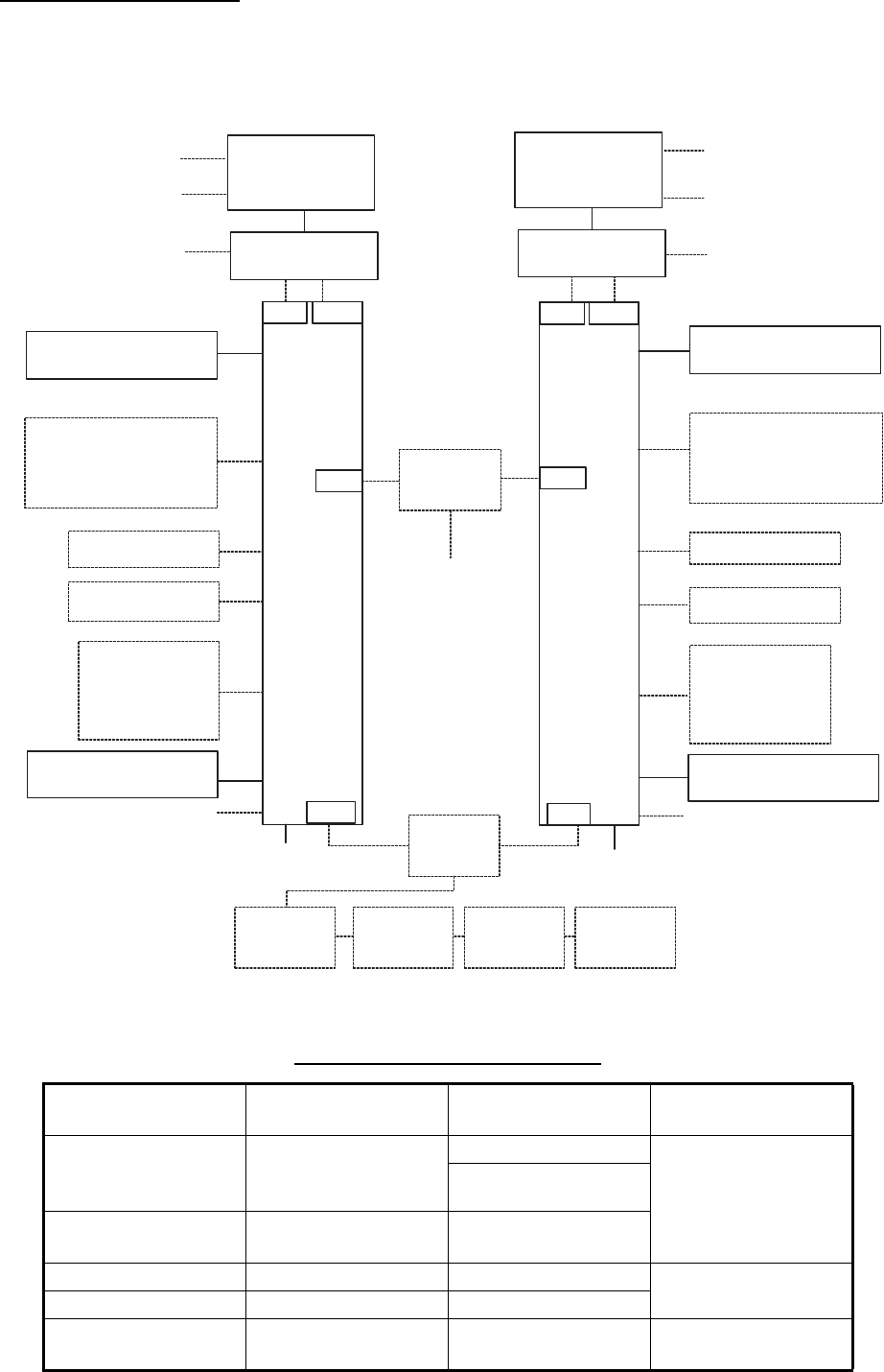
Interswitch connection
When multiple radars are used, connect, to the EC-3000, the HUB-3000 to the LAN1 port, and
HUB-100 to the LAN2 port. This configuration lets each radar as a standalone radar in case of
HUB malfunction.
Radar Component Combinations
RADAR
MODEL
ANTENNA
UNIT
TRANSCEIVER
UNIT
POWER SUPPLY
UNIT
FAR-3x10
FAR-3x20
XN12CF-RSB-128
XN20CF-RSB-128
XN24CF-RSB-128
RTR-105
PSU-014
RTR-106
FAR-3x20W XN20CF-RSB-130
XN24CF-RSB-130 RTR-108
FAR-3x30S SN36CF-RSB-129 RTR-107 PSU-014
PSU-015
FAR-3x30SW SN36CF-RSB-131 RTR-109
FAR-3x30S-SSD SN36CF-RSB-133 RTR-111 PSU-016
PSU-018
EC-3000
PROCESSOR
UNIT
Radar Control Unit RCU-025
Trackball Control Unit RCU-026
ECDIS Control Unit RCU-024
Radar Control Unit RCU-025
Trackball Control Unit RCU-026
(Max. 2)
Select one
Select one
Serial 1,2 (IEC 61162-2)
Serial 3-7 (IEC 61162-1)
VDR Switching
HUB
HUB-100
Sensor Adapter
MC-3000S
Serial
interface
Intelligent HUB
HUB-3000
POWER SUPPLY UNIT
ANTENNA UNIT
TRANSCEIVER UNIT
LAN3
LAN1
LAN2
100-230 VAC
1ø, 50-60 Hz
100-115/220-230 VAC
1ø, 50-60 Hz (For de-icer)
Sub Monitor
Gateway network
equipment
(Radar, ECDIS, etc.)
Serial8
LAN2
- Digital Out×6
(Power fail/system
fail/NO×2.NC×2)
- Digital in (ACK in)
Monitor Unit MU-190 MU-231
(or equivalent for -BB model)
Radar Control Unit RCU-025
Trackball Control Unit RCU-026
ECDIS Control Unit RCU-024
Radar Control Unit RCU-025
Trackball Control Unit RCU-026
(Max. 2)
Select one
Select one
Serial 1,2 (IEC 61162-2)
Serial 3-7 (IEC 61162-1)
VDR
- Digital Out×6
(Power fail/system
fail/NO×2.NC×2)
- Digital in (ACK in)
EC-3000
PROCESSOR
UNIT
LAN3 Serial8
LAN1
100-230 VAC
1ø, 50-60 Hz
Sub Monitor
100-115/220-230 VAC
1ø, 50-60 Hz 100-115/220-230 VAC
1ø, 50-60 Hz
Sensor Adapter
MC-3010A
Sensor Adapter
MC-3020D
Sensor Adapter
MC-3030D
Analog
interface
Digital in
interface
Digital out
interface
POWER SUPPLY UNIT
ANTENNA UNIT
TRANSCEIVER UNIT
100-115/220-230 VAC
1ø, 50-60 Hz (For de-icer)
Monitor Unit MU-190 MU-231
(or equivalent for -BB model)

vi
EQUIPMENT LISTS
Standard Supply
Console Type
Name Type Code No. Qty Remarks
Antenna Unit SN36CF-RSB133-111 - 1
Control Unit RCU-025 - Select
one
Standard type
RCU-026 - Trackball type
Power
Supply Unit
PSU-016 - Select
one
For 24rpm
PSU-018 - For 42rpm
Processor Unit EC-3000 - 1
Monitor Unit MU-190 - Select
one
For FAR-3230S-SSD
MU-231 - For FAR-3330S-SSD
Installation
Materials
CP03-35202 001-249-880 1 For antenna
CP03-35402 001-255-430 1 For RSB
CP03-35404 001-270-080 1 For RSB (w/de-icer)
CP03-35500 000-024-096
Select
one
15 m cable
CP03-35510 000-024-097 30 m cable
CP03-35520 000-024-098 40 m cable
CP03-35530 000-024-099 50 m cable
CP03-35301 001-249-770 1 For PSU-016/018
CP24-02120 000-024-925 1 For EC-3000
CP24-02200 000-022-508 1 For RCU-025
CP24-02300 000-022-509 1 For RCU-026
Accessories FP24-00603 001-285-760 1 For EC-3000
FP24-00701 001-170-820 1 For RCU-025
FP24-00801 001-170-920 1 For RCU-026
Spare Parts SP24-00601 001-170-660 1 For EC-3000, Fuse: FGMB
125V 10A PBF (000-157-
470-10, 3 pcs.)
SP24-00602 001-170-670 1 For EC-3000, Fuse: FGMB
250V 5A PBF (000-157-570-
10, 3 pcs.)
SP03-17661 001-249-420 1 For PSU-016, Fuse: FGBO
250V 5A PBF (000-155-840-
10, 2 pcs.)
SP03-17651 001-249-750 1 For PSU-018, Fuse: FGBO
250V 7A PBF (000-178-084-
10, 2 pcs.), FGBO 250V 3A
PBF (000-155-841-10, 2
pcs.)
Hoist S-band
Antenna
Manual
C32-01303-* - 1
Name Type Code No. Qty Remarks
Display Unit RCN-303 - 1 w/FAR-3230S-SSD
RCN-304 - 1 w/FAR-3330S-SSD

EQUIPMENT LISTS
vii
Optional Supply
Name Type Code No. Remarks
LAN Signal
Converter
OP03-223-1 -
Cable
Extension Kit
OP03-224-1 001-254-390
De-icer Kit OP03-227 001-254-330
Rectifier Unit RU-3424 - For 220 VAC
RU-1746B-2 -
Transformer
Unit RU-1803 - Converts 440 VAC to 100 VAC, for pro-
cessor unit
RU-3305-0 - Converts 110/115/220/230 VAC to 100
VAC, for deicer
RU-5693 - Converts 110 VAC to 220 VAC, for
transceiver unit
RU-6522 - Converts 220 VAC to 200 VAC, for
transceiver unit
RU-5466-1 - Converts 440 VAC to 220 VAC, for
transceiver unit
Control Unit RCU-024 - ECDIS standard type
RCU-026 - Trackball type
LAN Cable
Assy.
MOD-Z072-050+ 001-167-890-10
Sensor
Adapter
MC-3000S - Serial type
MC-3010A - Analog IN
MC-3020D - Digital IN
MC-3030D - Digital OUT
Intelligent HUB HUB-3000 -
Switching HUB HUB-100 - See manual of HUB-100.
AC/DC Power
Supply Unit
PR-240 -
Installation
Materials
CP03-28900(10M) 000-082-658 FR-FTPC-CY 10 m, for sensor adaptor
CP03-28910(20M) 000-082-659 FR-FTPC-CY 20 m, for sensor adaptor
CP03-28920(30M) 000-082-660 FR-FTPC-CY 30 m, for sensor adaptor
CP24-02900(10M) 001-208-050 LAN cable 10 m, for HUB-3000
CP24-02910(20M) 001-208-060 LAN cable 20 m, for HUB-3000
CP24-02920(30M) 001-208-040 LAN cable 30 m, for HUB-3000
Connector CP03-28901 008-542-460
Bracket
Assembly
OP26-5 000-016-270 For MU-190
OP26-15 001-116-730 For MU-231
Flush Mount
Kit
OP26-12 001-116-280 For MU-190
OP26-17 001-116-750 For MU-231
Hood Assem-
bly
OP26-6 001-080-930 For MU-190
OP26-16 001-116-740 For MU-231

EQUIPMENT LISTS
viii
Cable Assy DVI-D/D
S-LINK 5M
001-132-960-10 Between processor and control units, 5
m
DVI-D/D
S-LINK 10M
001-133-980-10 Between processor and control units,
10 m
6TPSH-XH12X2-
L5.0SP1
001-186-260-10 For RCU-024/025, 5 m
6TPSH-XH12X2-
L10SP1
001-186-270-10 For RCU-024/025, 10 m
6TPSH-XH12X2-
L20SP1
001-186-280-10 For RCU-024/025, 20 m
6TPSH-XH12X2-
L30SP1
001-186-290-10 For RCU-024/025, 30 m
6TPSH-XH12X2-
L5.0SP2
001-186-310-10 For RCU-026, 5 m
6TPSH-XH12X2-
L10SP2
001-186-320-10 For RCU-026, 10 m
6TPSH-XH12X2-
L20SP2
001-186-330-10 For RCU-026, 20 m
6TPSH-XH12X2-
L30SP2
001-186-340-10 For RCU-026, 30 m
DSUB9P-X2-L5M 001-188-260 For MU-190/231 brill control, 5 m
DSUB9P-X2-L10M 001-188-270 For MU-190/231 brill control, 10 m
OP24-32 001-188-300 USB cable, between processor unit and
control unit
DVI-BNCX5-L2000 001-204-150 For VDR connection
DSUB9P-X2-L5M-
WP
001-207-890 For monitor unit, 5 m, waterproofing
type
DSUB9P-X2-L10M-
WP
001-207-900 For monitor unit, 10 m, waterproofing
type
DSUB9P-X2-A-L5M 001-252-580 For Hatteland display
DSUB9P-X2-A-L10M 001-252-590 For Hatteland display
Monitor Unit MU-190 - For FAR-3230S-SSD(-BB)
MU-231 - For FAR-3330S-SSD
Terminal
Opener
OP24-33 001-188-850
Cable MC1.5-W-L600 001-187-470-10 For sensor adapters, 6 m
MC1.5-W-L1000 001-187-480-10 For sensor adapters, 10 m
MC1.5-W-L2000 001-187-490-10 For sensor adapters, 20 m
MC1.5-W-L3000 001-187-500-10 For sensor adapters, 30 m
Crimping Tool CRIMPFOX10S 001-206-920 For ferrule for sensor adaptor
Spare Parts SP24-00801 (BOX) 001-235-320 For HUB-3000
Program Instal-
lation Software
OP03-230 001-285-780 DVD-R
Operator’s
Manual
OME-36160-* -
OMJ-36160-* -
Magnetron Re-
place Instruc-
tion Manual
E32-01306-* -
J32-01306-* -
Name Type Code No. Remarks
EQUIPMENT LISTS
ix
About the category sticker
This radar meets the requirements in IEC62388 (Marine naviga-
tion and radio communication equipment and systems-Ship born
radar-Performance requirements, method of testing and required
test results.) Check the appropriate box on the sticker which is
pre-attached on the processor unit, according to your radar’s
specification. Refer to the table shown below to confirm your cat-
egory.
Category Radar type ANT, rotation speed
CAT 1C FAR-3330S-SSD 24 rpm
CAT 1HC Same model as above 42 rpm
CAT 2C FAR-3230S-SSD, FAR-3230S-SSD-BB 24 rpm
CAT 2HC Same models as above 42 rpm
Comply with MSC.192(79)
CAT 1C
CAT 2C
CAT 1HC
CAT 2HC
Sticker for category
EQUIPMENT LISTS
x
This page is intentionally left blank.
1-1
1. INSTALLATION
1.1 Antenna Unit
1.1.1 Installation considerations
• The antenna unit is generally installed either on top of the wheelhouse or on the ra-
dar mast, on a suitable platform. Locate the antenna unit in an elevated position to
permit maximum target visibility.
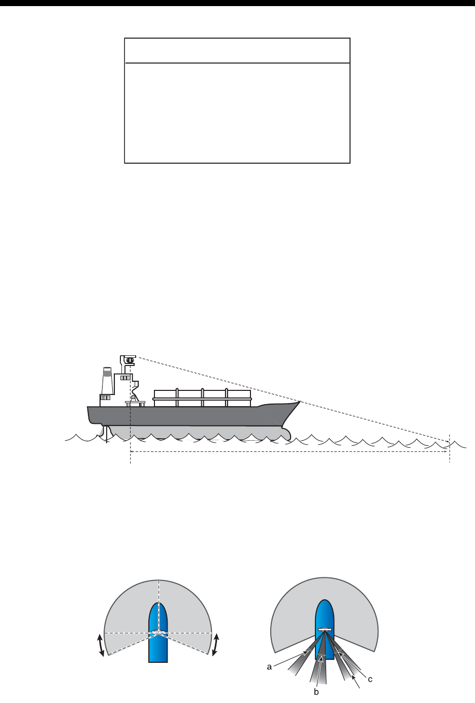
• A line of sight from the antenna unit to the bow of the ship must hit the surface of
the sea in not more than 500 m or twice the ship’s length, depending whichever val-
ue is smaller, for all load and trim conditions.
• Install the antenna unit so that any blind sectors caused by objects (mast, etc.) are
kept to a minimum. A blind sector must not exist in arc of the horizon from right
ahead to 22.5° aft of the beam to either side (see the figure below). Also, individual
blind sectors of more than 5°, or the total arc of both blind sectors of more than 20°,
must not occur in the remaining arc (Figure 2). Note that any two blind sectors sep-
arated by 3° or less are regarded as one sector.
NOTICE
Do not apply paint, anti-corrosive
sealant or contact spray to coating or
plastic parts of the equipment.
Those items contain organic solvents that
can damage coating and plastic parts,
especially plastic connectors.
less than 500 m or twice the ship's length
Figure 1 Figure 2
less than 3°
22.5°
22.5°
270° 90°
a, b, c: less than 5° respectively
a+b+c+... : less than 20°
a, b, c: less than 5° respectively
a+b+c+... : less than 20°
1. INSTALLATION
1-2
• Do not install the antenna where extreme winds may strike the port and starboard
sides of the antenna.
• Install the antenna unit away from interfering high-power energy sources and TX ra-
dio antennas.
• Keep the lower edge of the antenna unit above the safety rail by at least 500 mm.
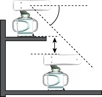
• Install two antenna units as shown in the
right figure.
• No funnel, mast or derrick shall be within the vertical beamwidth of the antenna unit
in the bow direction, especially zero degree ±5°, to prevent blind sectors and false
echoes on the radar picture.
• It is rarely possible to place the antenna unit where completely clear view in all di-
rections is available. Therefore, you should determine the angular width and relative
bearing of any shadow sectors for their influence on the radar at the first opportunity
after fitting.
• Locate the antenna of EPFS clear of the radar antenna to prevent interference to
the EPFS. A separation of more than two meters is recommended.
• A magnetic compass will be affected if the antenna unit is placed too close to the
magnetic compass. Observe the compass safe distances on page ii to prevent in-
terference to a magnetic compass.
• Do not paint the radiator aperture, to ensure proper emission of the radar waves.
• Ground the unit with the ground wire (supplied).
• Deposits and fumes from a funnel or other exhaust vent can affect the aerial perfor-
mance and hot gases may distort the radiator portion. Do not install the antenna unit
where the temperature is more than 55°C.
• Leave sufficient space around the unit for maintenance and servicing. See the an-
tenna unit outline drawing for recommended maintenance space.
Note: For more information, please refer to IMO SN/Circ.271 “Guidelines for the in-
stallation of shipborne radar equipment”.
more than 20°
more than 1 m
1. INSTALLATION
1-3
1.1.2 Installation precaution for S-band antenna unit
If an S-band antenna unit is mounted near the end of a platform to provide sufficient
rotation clearance for the radiator, the antenna unit, because of its weight, swings up
and down by ship’s vibration and rolling. This exerts excessive levels of stress at the
base of the radiator, which can damage the radiator. To prevent this, relocate the an-
tenna unit, or if relocation is not possible, reinforce the platform.
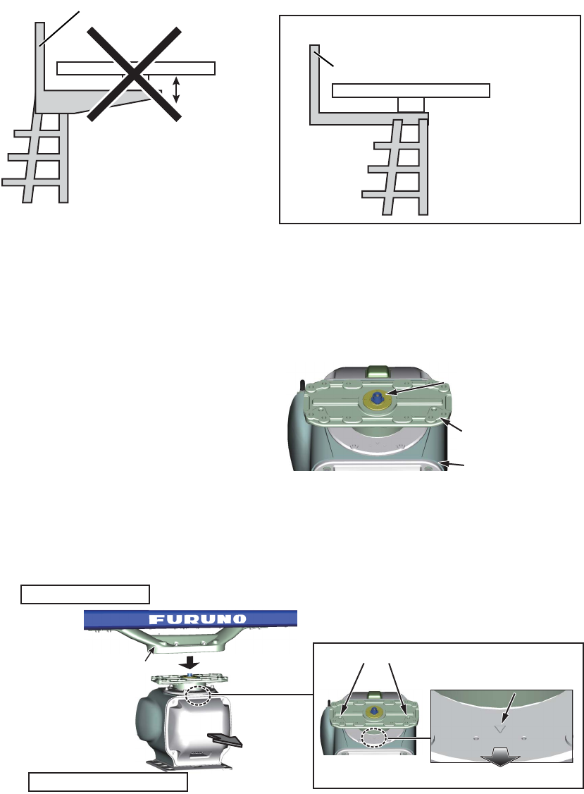
1.1.3 How to assemble the antenna unit
The antenna unit consists of the antenna radiator (w/antenna support) and the anten-
na unit chassis, and they are packed separately. Fasten the antenna radiator to the
antenna unit chassis as follows:
1. Remove the protective waveguide
cap from the waveguide on the ra-
diator bracket.
2. Put the radiator on the radiator bracket so the guide pins of the antenna support
fits into the guide pin holes on the radiator bracket. (Orient the logo of the radiator
to the side with bow mark on the bracket. If reversely oriented the radiator cannot
be set to the bracket.)
3. Coat the threads of eight hex bolts (M12×50, supplied) with marine sealant sup-
plied.
Mast for DF, etc.
Mount the antenna
unit directly on the
mast or on the
platform, as near as
possible to center of
the mast.
Remarkable
vibration
(pitching)
Mounting
position
EXAMPLE
Mast for DF, etc.
Waveguide cap
Radiator bracket
Antenna shassis
Antenna unit chassis
Antenna support
Antenna radiator
Front
BowBow
Bow markBow mark
Guide pin holesGuide pin holes
1. INSTALLATION
1-4
4. Set the antenna radiator to the radiator bracket from the bottom of the bracket with
the eight hex bolts, spring washers and flat washers. The torque must be 49 N•m.
5. Coat the screws fixed at step 4 with ma-
rine sealant (supplied) as shown in the
right figure.
6. Connect the coaxial cable from the an-
tenna unit to the rotary joint. The torque
must be 25 N•m.
Note 1: The connector of the coaxial
cable must be connected vertically.
Note 2: The coaxial cable must be hor-
izontal and must not contact the hole of
the antenna support.
Note 3: If the coaxial cable is long, bend the cable some distance from the con-
nector. Insert surplus cable into antenna support. Connect the cable to the rotary
joint straightly.
7. Coat the hex bolts (M12×40, 4 pcs.) for the support cover with marine sealant
(supplied).
8. Fasten the support cover with the bolts, spring washers and flat washers. The
torque must be 20 N•m.
Note 1: Make sure the safety rope does not contact the antenna support cover.
Note 2: Set the screw for the safety rope to come to the left when viewed from the
front side of the antenna.
Bottom view of the bracket
(eight places)
(eight places)
Hex bolt
(with marine sealant)
Flat washer
Spring washer
Coat with marine
sealant.
Connect vertically.
Connect vertically.
Hole of Antenna
support
Hole of Antenna
support
Connect the cable straightly.
Connect the cable straightly.
Screw
(four places)
Screw
(four places)
Antenna support cover
Antenna support cover
Safety rope
Safety rope
Front view
Left when viewed from the front side
1. INSTALLATION
1-5
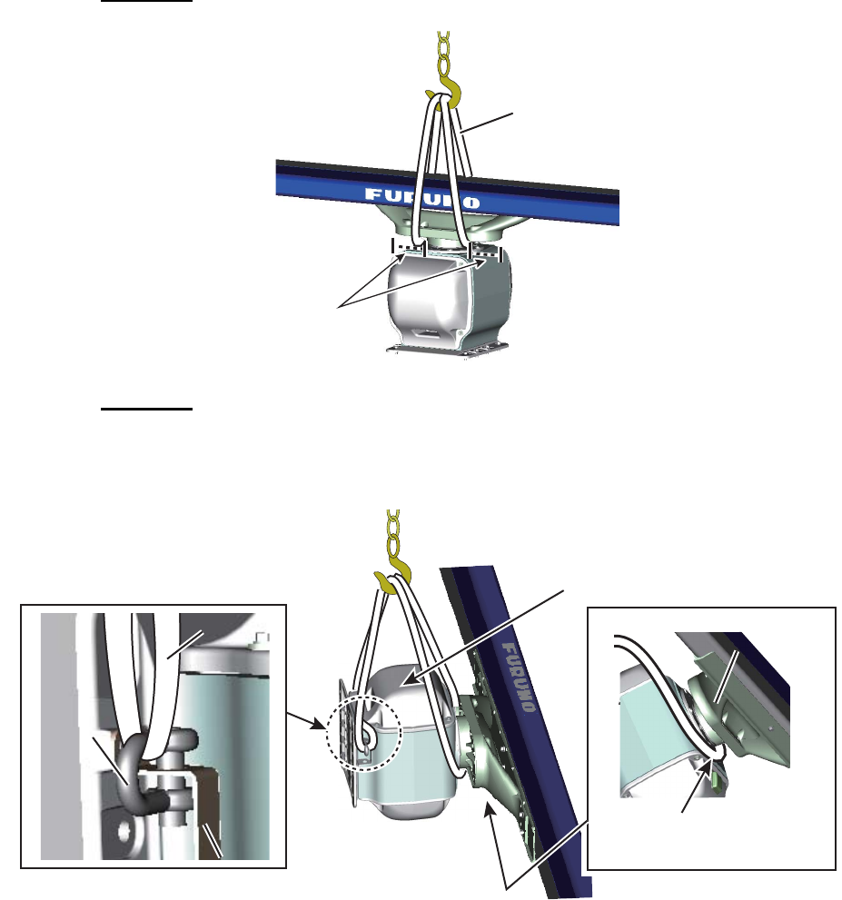
1.1.4 How to hoist the antenna unit
The antenna unit may be assembled before hoisting it to the mounting platform. Attach
lifting belt slings to the chassis, NOT the antenna radiator, as shown in the figure be-
low.
There are two methods to hoist the antenna unit.
Method 1
Method 2
Fasten belt sling to a shackle, pass belt sling around antenna support and fasten other
end of belt sling to other shackle.
Set belt slings to
antenna support.
Belt sling
Bow side up
Pass belt sling around
antenna support.
Antenna support
Antenna support
Shackle
(left, right)
Shackle
(left, right)
Lifting fixture (ø20)
Lifting fixture (ø20)
Belt sling
Belt sling
1. INSTALLATION
1-6
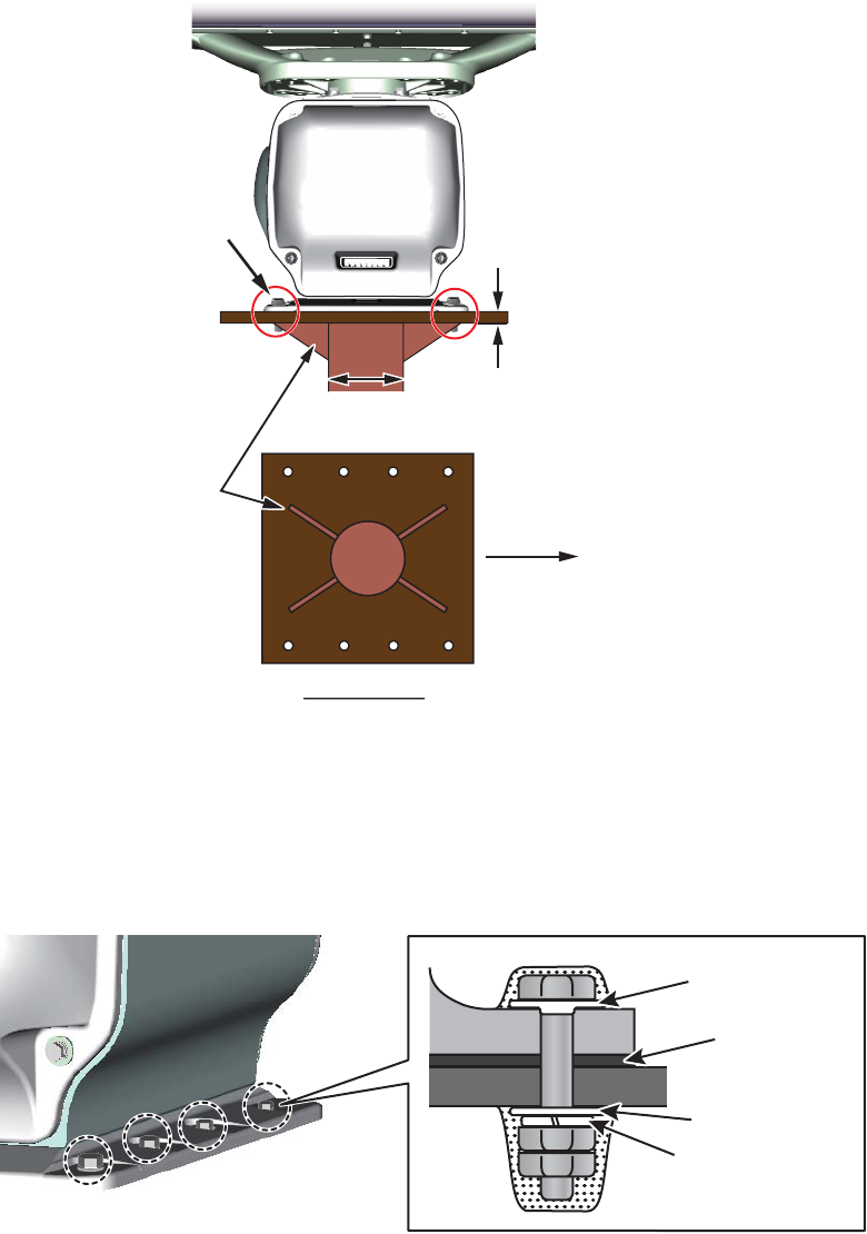
1.1.5 How to fasten the antenna unit to the mounting platform
1. Construct a suitable mounting platform referring to the outline drawing at the end
of this manual.
• The diameter of the mast for fixing the antenna unit platform must be over 250
mm.
• The thickness of the antenna unit platform must be over 15 mm.
• The reinforcement rib must be installed diagonally as shown below.
2. Referring to the outline drawing, drill eight mounting holes in the mounting plat-
form.
3. Put the antenna unit on the mounting platform, then orient the unit so the bow
mark on its base is facing the ship’s bow.
4. Fasten the antenna unit to the mounting platform with M12×70 hex bolts, nuts, flat
washers, spring washers and seal washers (supplied). The torque must be 49
N•m.
Note: The bolts can also be inserted from the underside of the platform.
Over 15 mm
250 mm diameter or more, 6 mm thick or more
Use two nuts.
Ship's bow
Install the
reinforcement
rib diagonally.
Bottom view
Seal washer
Corrosion
proof rubber
mat
Use two nuts.
(Torque 49 N•m)
Flat washer
Spring washer
M12×70
(eight places)
1. INSTALLATION
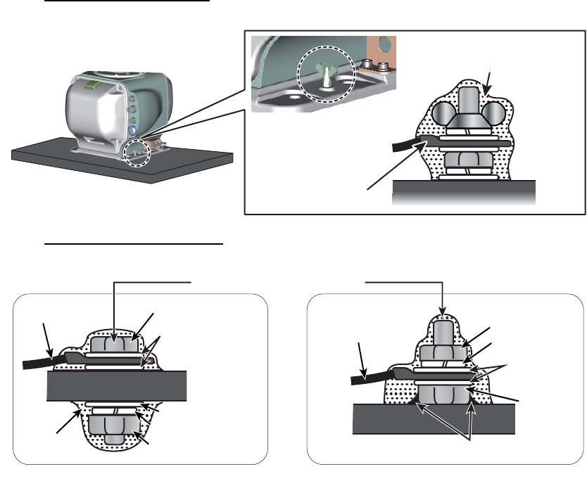
1-7
5. Using a hex bolt (M6×x25), nut (M6), spring washer (M6) and flat washer (M6),
establish the ground system on the mounting platform as shown below. The loca-
tion must be within 340 mm of the ground terminal on the antenna unit. Connect
the ground wire (RW-4747, 340 mm, supplied) between the grounding point and
ground terminal on the antenna unit. Coat the hardware of the ground system with
the marine sealant (supplied).
Antenna chassis side
Mounting platform side
Ground wire Antenna chassisAntenna chassis
Fasten ground wire then
coat with marine sealant.
Marine
sealant
Marine
sealant
Hex bolt
OR
Ground wire Hex nut
Arrange ground terminal as close as possible to antenna unit.
Hex bolt
Flat washer
Hex nut
Spring washer
Flat washer
Spring washer
Ground wire
Coat with marine sealant.
Flat washer
Mounting PlatformMounting Platform
Welding
Mounting PlatformMounting Platform
1. INSTALLATION
1-8
1.2 Monitor Unit
See the operator’s manual for MU-190 (OMC-44670) or MU-231 (OMC-44690). Keep
in mind the following points when selecting a location.
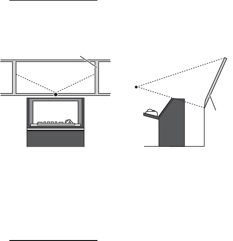
Installation considerations
• Locate the monitor unit not to block the view from the bridge window because of the
frame of the window.
• Locate the monitor unit under the condition which the ambient illumination is easy
to observe.
1.3 Radar Control Unit, Trackball Control Unit
The control units can be installed on a desktop or flush mounted in a console. For the
desktop installation the unit can laid flat or tilted.
Note: The control unit RCU-025 can be used instead of the RCU-020 (for FAR-2xx7)
mounted in the connection stand (OP03-184 or OP26-20) using the optional kit
OP24-31.
Installation considerations
Keep in mind the following points when selecting a location.
• Select a location where the control unit can be operated easily.
• Locate the unit away from heat sources because of heat that can build up inside the
cabinet.
• Locate the equipment away from places subject to water splash and rain.
• Leave sufficient space at the sides and rear of the unit to facilitate maintenance.
• Determine the mounting location considering the length of the signal cable between
the control unit and the processor unit.
• A magnetic compass will be affected if the control unit is placed too close to the
magnetic compass. Observe the compass safe distances in the SAFETY IN-
STRUCTIONS prevent interference to the compass.
• Be sure to connect the ground wire (between the earth terminal on the chassis and
the ship’s earth).
Bridge
window
Viewing point
Viewing point
Viewing point
Viewing point
Bridge window
1. INSTALLATION
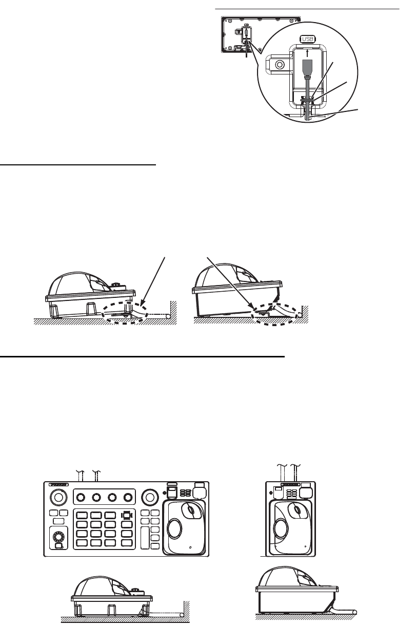
1-9
• Fasten the USB cable with the cable
tie.
1.3.1 Desktop installation
How to mount the unit tilted
Use the desk fixing plate to mount the unit tilted.
1. Fix the desk fixing plate to the bottom of the control unit.
2. Fix the control unit with self-tapping screws (φ5×20, local supply).
How to mount the unit flush with mounting surface
Do this installation to install the control unit flat on the mounting surface.
1. Drill four mounting holes of 5 mm (4 mm, for RCU-026) diameter referring to the
outline drawing at the back of this manual.
2. Fix the control unit with four screws, M4, local supply (M3, for RCU-026), from the
underside of the desktop.
Ex. Radar control unit, bottom view RCU-025
USB cableUSB cable
Cable tieCable tie
Cable routing pegCable routing peg
Desk fixing plate
RCU-026RCU-025
RCU-026
RCU-025
1. INSTALLATION
1-10
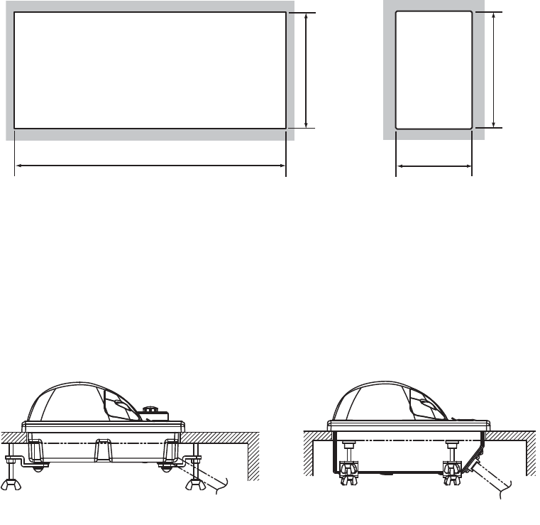
1.3.2 Installation in a console
Use the optional flush mount kit (OP24-24 for RCU-024/025, OP24-27 for RCU-026)
to install the control unit in a console.
Note: For flush mounting in a panel, the mounting surface must be flat. Do not install
the unit on an uneven surface.
1. Prepare a cutout in the location as shown in the figure as below.
2. Set the control unit to the cutout.
3. Attach the mounting plate to the control unit with four screws from the rear side.
4. Insert the wing nut (or hex. nut) to each wing screw then fix the wing screw to each
mounting plate.
5. Fasten each wing screw and then fasten the wing nuts (or hex. nuts) as shown in
figure below.
388±2 110±2
170±2
170±2
For RCU-024/025 For RCU-026
RCU-024/025 RCU-026
1. INSTALLATION
1-11
1.4 Power Supply Unit (PSU-016/PSU-018)
1.4.1 Installation considerations
The Power Supply Unit can be mounted on a bulkhead or deck. Keep in mind the fol-
lowing points when selecting a location.
• Locate the unit away from heat sources because of heat that can build up inside the
cabinet.
• Select a location where the vibration is minimal.
• Locate the equipment away from places subject to water splash and rain.
• Make the service clearance of 100 mm in front of the vent hole (front and rear sides).
• Leave sufficient space at the sides and rear of the unit to facilitate maintenance.
• Connect the ground wire between the earth terminal on the chassis and the ship’s
earth.
• A magnetic compass will be affected if the unit is placed too close to the magnetic
compass. Observe the compass safe distances on page ii to prevent disturbance to
the compass.
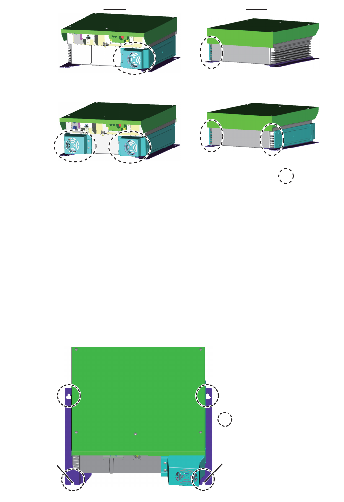
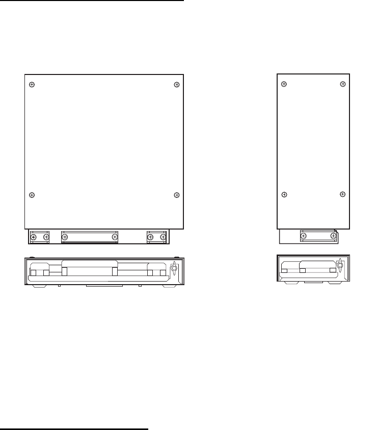
1.4.2 How to mount the power supply unit
Use four bolts (M6, local supply) to fix the power supply unit.
Note: For bulkhead mounting, the notches on the unit must face the deck.
Front Rear
(PSU-016)
(PSU-018)
: vent hole
(ex: PSU-016)
: Bolt holes
Notch
Notch
1. INSTALLATION
1-12
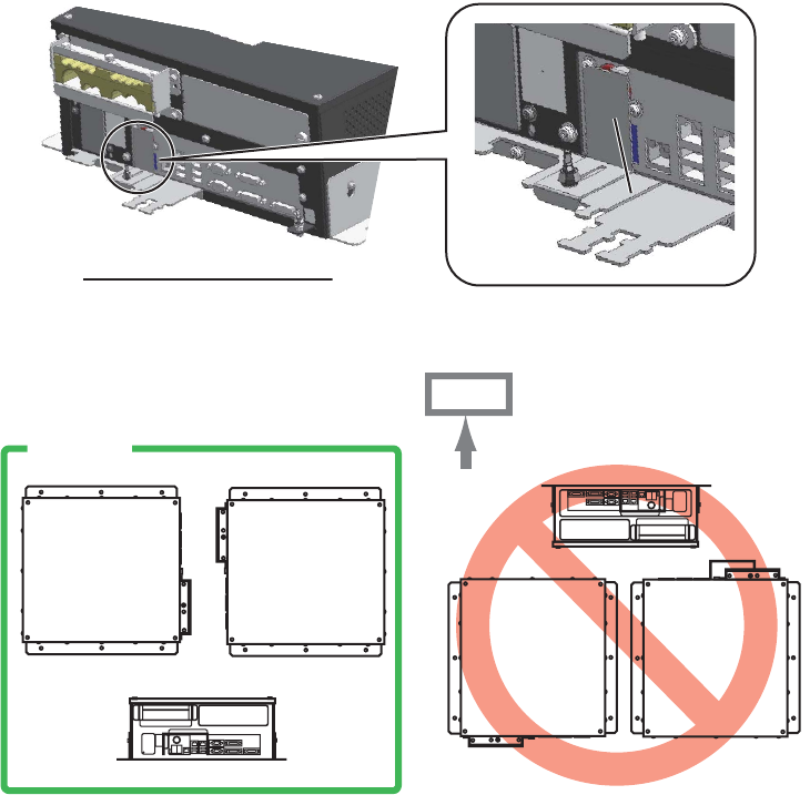
1.5 Processor Unit
1.5.1 Installation considerations
Keep in mind the following points when selecting a location.
• Locate the processor unit away from heat sources because of heat that can build
up inside the cabinet.
• Select a location where the vibration is minimal.
• Locate the equipment away from places subject to water splash and rain.
• Make the service clearance of 100 mm in front of the vent hole (left side).
• Leave sufficient space at the sides and rear of the unit to facilitate maintenance.
• Be sure to connect the ground wire (between the earth terminal on the chassis and
the ship’s earth).
• A magnetic compass will be affected if the processor unit is placed too close to the
magnetic compass. Observe the compass safe distances in the "SAFETY IN-
STRUCTIONS" to prevent interference to a magnetic compass.
• Leave the dummy plate fastened, to prevent the wrong operation of the power
switch. The items behind the plate are for use by the serviceman.
• Install the processor unit on the floor, or on a bulkhead with the following direction
(horizontal), because of the DVD drive unit.
Processor unit, front view
Keep the dummy
plate in this position.
Keep the dummy
plate in this position.
OK
UP
1. INSTALLATION
1-13
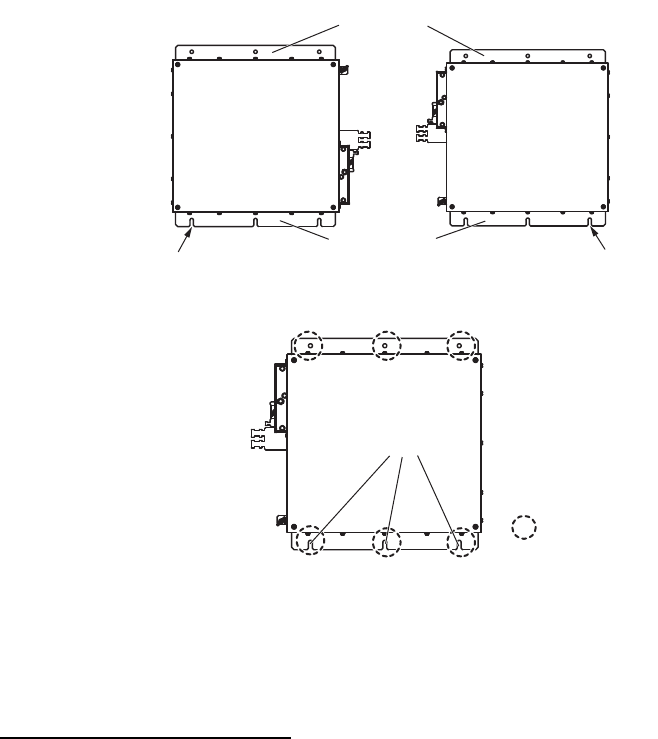
1.5.2 How to install the processor unit
Use four bolts (M6, local supply) to fix the processor unit.
1. Use 10 binding head screws (M4×8, supplied) to attach the chassis bases 1 and
2 to the processor unit.
Note: For bulkhead mounting, attach the chassis base 2 so that the notches on it
are facing the deck.
2. Use six bolts (M6, local supply) to fix the processor unit.
1.6 Sensor Adapter MC-3000S/3010A/3020D/3030D
(option)
Installation considerations
When you select a mounting location, keep in mind the following points:
• Locate the adapter away from heat sources because of heat that can build up inside
the cabinet.
• The vibration must be minimal.
• Locate the equipment away from places subject to water splash and rain.
• Be sure to connect the ground wire (between the earth terminal on chassis and the
ship’s earth).
• Leave sufficient space at the sides and rear of the unit to facilitate maintenance.
• A magnetic compass will be affected if the adapter is placed too close to the mag-
netic compass. Observe the compass safe distances in the "SAFETY INSTRUC-
TIONS" (on page i) to prevent interference to a magnetic compass.
• For MC-3000S, use a Cat5 cable of correspondence.
Chassis base 1
Chassis base 2
Notch Notch
: Bolt holes
Notch
1. INSTALLATION
1-14
• Select the mounting location considering the number of the sensor adapters con-
nected.
A maximum of eight MC-3000S can be connected to a sensor network (for the re-
dundant connection:16).
A maximum of 10 sensor adapters (MC-3010A/3020D/3030D) can be connected to
a MC-3000S. However, note that five MC-3010A can be connected.
• Select the location so that the length of the cables among the sensor adapters (MC-
3000S, 3010A, 3020D and 3030D) is less than 6 m. If the length is more than 6 m,
the adapters may not work properly.
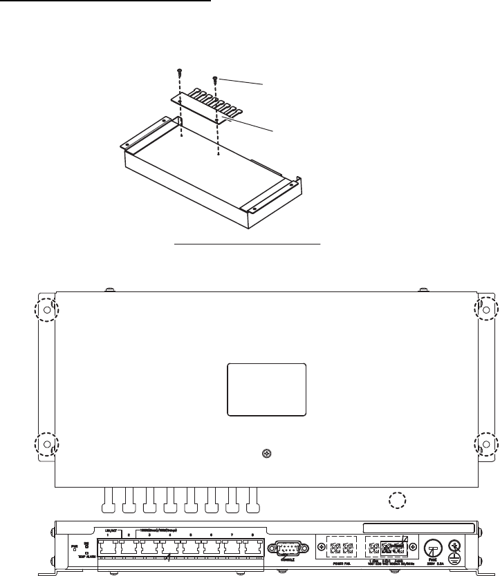
How to install the sensor adapter
1. Unfasten four binding screws to remove the cover from the sensor adapter.
2. Fasten four self-tapping screws (φ4×20, supplied) to fix the sensor adapter.
3. Reattach the cover.
1.7 Intelligent Hub HUB-3000 (option)
Use the optional Intelligent Hub HUB-3000 to connect gateway network equipment.
Do not connect this network to the shipborne LAN network. Further, do not connect a
PC to this network, other than for maintenance.
Installation considerations
Keep in mind the following considerations when selecting a location.
• Locate the hub away from heat sources because of heat that can build up inside the
cabinet.
• The vibration must be minimal.
• Locate the equipment away from places subject to water splash and rain.
• Be sure to connect a ground (between the earth terminal on chassis and the ship’s
earth).
• Leave sufficient space at the sides and rear of the unit to facilitate maintenance.
MC-3000S MC-3010A/3020D/3030D
1. INSTALLATION
1-15
• A magnetic compass will be affected if the adapter is placed too close to the mag-
netic compass. Observe the compass safe distances in the "SAFETY INSTRUC-
TIONS" (on page i) to prevent interference to a magnetic compass.
How to install the HUB-3000
1. Use two binding screws (M3×6, supplied) to attach the cable clamp (supplied) to
the bottom of the HUB-3000.
2. Fasten four self-tapping screws (φ4×20, supplied) to fix the unit.
HUB-3000, bottom view
Cable clamp
Binding screw
(M3×6, 2 pcs)
: Screw holes

1. INSTALLATION
1-16
1.8 Switching Hub HUB-100 (option)
Use the optional Switching Hub HUB-100 to connect sensor networks. This network
cannot be connected to the shipborne LAN network. Further do not connect a com-
mercial PC to this network, other than for the maintenance.
For the installation procedures, see the operator’s manual for HUB-100 (Pub. No.
OMC-35191).
Installation considerations
Keep in mind the following points when selecting a location.
• Locate the hub away from heat sources because of heat that can build up inside the
cabinet.
• The vibration must be minimal.
• Locate the equipment away from places subject to water splash and rain.
• Make sure that the ground wire is connected between the earth terminal on chassis
and the ship’s earth.
• Leave sufficient space at the sides and rear of the unit to facilitate maintenance.
• A magnetic compass will be affected if the adapter is placed too close to the mag-
netic compass. Observe the compass safe distances in the SAFETY INSTRUC-
TIONS to prevent compass malfunction.

2-1
2. WIRING
2.1 Overview
Cabling considerations
To lessen the chance of picking up electrical interference, avoid where possible rout-
ing the antenna cable (power and LAN) near other onboard electrical equipment (ra-
dars, TX radio antennas, etc.). Also avoid running the cable in parallel with power ca-
bles. When crossing with other cable, the angle must be 90° to minimize the magnetic
field coupling.
The antenna cable between the antenna, PSU and processor units is available in
lengths of 15 m, 30 m, 40 m, and 50 m. Whatever length is used, it must be unbroken;
namely, no splicing allowed. Use the antenna cable as short as possible to minimize
attenuation of the signal.
The radar must be connected to an emergency power source, as required by SOLAS
II-1.
About network construction
About wiring
• Use the optional Switching Hub HUB-100 to connect the sensor networks. For the
gateway networks, use the optional Intelligent Hub HUB-3000.
• Do not connect the ship’s LAN network to the optional HUBs. Also, commercial PCs
cannot be connected to the gateway network, other than for maintenance.
• To connect the FEA-2xx7, FCR-2xx9, FMD-32x0 or FAR-2xx7 series via LAN net-
work, use the INS net-work.
• Use the optional USB cable (type: OP24-32) to connect to the USB port on the control
unit.
• The length of the USB cable should be within 5 m to prevent equipment trouble.
• The length of LAN cables must be within 50 m.
• Use the Cat5e or Cat6 LAN cable for the network if available locally.
• If LAN cables are not available locally, use the optional LAN cables (FR-FTPC-CY for
sensor network, DTI-C5E350 VCV for gateway network).
• If extension or division of the DVI or RGB cables is necessary, use the dividers shown
below.
• DVI cable divider: DVI-12A (maker: IMAGENICS)
• RGB divider: CIF-12H, DD-106 or WBD-14F (maker: IMAGENICS)
• Make sure that the ground wires are connected between the ground terminals on each
equipment and the ship’s earth.
• If a UPS (user supply) is connected to this equipment, be sure that the grounding lamp
does not light.
• The output from the UPS must be a sine wave, as
in the right figure.
50Hz
60Hz
2. WIRING
2-2
Standard wiring
A Cat 5e LAN cable (RW-00135) connects between the antenna unit and the power
supply unit (PSU). The maximum length of the cables between the Processor Unit and
the antenna unit is 80 m.
100-230 VAC
Antenna Unit
DPYC-2.5
: Cable requires fabrication
DSUB9P-DSUB9P
5 m/10 m
Processor Unit
EC-3000
100-230 VAC
DVI-D/D SINGLE LINK
5 m/10 m
MU-190
(for
FAR-3230S-SSD(-BB)
)
MU-231
(for
FAR-3330S-SSD
)
PSU-016/018
Sensor Adapter
or HUB-100
Serial: TTYCS-1Q
FR-FTPC-CY
100-230 VAC
GYRO, AIS
TTYCS-4
×2
GPS, LOG, E/S,
WIND, ALARM,
NAVTEX, etc.
TTYCS-1Q
×5
5 m
(for USB)
30 m
×2
TTYCS-10
Monitor
Unit
DPYC-1.5
VDR
RGB cable
IEC60320-C13-L5M
HUB-3000
5 m
(for USB)
30 m
USB
memory
Radar
Control Unit
RCU-025
Trackball
Control Unit
RCU-026
USB
memory
LAN Power
RW-00135
15/30/40/50 m
100-115/220-230 VAC
Power Supply Unit
DTI-C5E 350 VCV
(10/20/30 m)
LAN: DTI-C5E 350 VCV (10/20/30 m)
(or Cat 5e LAN cable (local supply))
I/O Board
LAN: MOD-Z072-050+
Sub monitor
RW-00136
15/30/40/50 m
De-icer
DPYCY-1.5
100-115/
220-230 VAC
ALARM
SYSTEM
2. WIRING
2-3
2.2 Antenna Unit
Three cables are connected to the antenna unit: antenna cable, cable for the sub mon-
itor (option) and power cable for the deicer (option). The procedure shows how to con-
nect all cables. Disregard the descriptions for the optional equipment if not applicable.
2.2.1 How to fabricate the cables
Antenna cable RW-00135
See "How to fabricate the LAN cable" on page 2-12 for how to attach the LAN cable
connector.
Antenna cable RW-9600/6895/4873 (for retrofit installation)
The optional LAN signal converter kit is required for retrofit installation. For wiring in
case of a retrofit, see section 2.7.
For RW-9600: The white, red, and green wires are not used. Attach a single crimp-on
lug (FV5.5-S4(LF), yellow) locally to the wires. (These wires will be connected togeth-
er with the shield of the power line, in the next section.)
For RW-6895/4873: Fifteen wires are not used. Cut the wires and bind them with vinyl
tape. Do not connect the wires to ground.
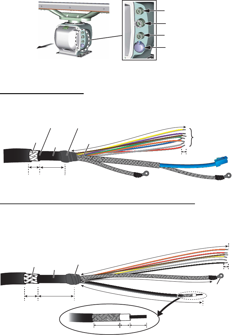
Rear side
Antenna motor switch
Cable for sub monitor
Cable for antenna
Cable for deicer
ShieldShield
ArmorArmor
LAN cable
6
500500
Power line
Remove the vinyl tape.
30
10
SheathSheath
SheathSheath
Vinyl tape
Armor Sheath
Crimp-on lug
ShieldShield
470470
SheathSheath
Vinyl tape
Coaxial
cable
Coaxial
cable
6
10 30
14 59
500500
400400
2. WIRING
2-4
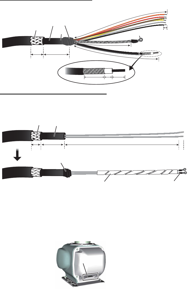
Cable RW-00136 (for a sub monitor)
Cable DPYCY-1.5 (for the optional deicer)
Wrap the supplied spiral tube around the power cable for de-icer, starting from the pc
board.
2.2.2 How to connect the cables
Note: If there is a chance of inclement weather when the RF unit is removed, cover
the intakes on the front and rear covers with packing tape. Be sure to remove the tape
after completing the installation.
Armor
Crimp-on lug
Sheath
Sheath
Sheath
Coaxial
cable
Shield
6
14 59
10 30
390
390
410
410
Vinyl tape
270
270
SheathSheath
Armor SheathSheath
6
30
10 1270
Crimp-on lug
(FV2-M4)
Wrap spiral tube.
Vinyl tape
ex) Front side
Intake (Cover with packing tape)
Intake (Cover with packing tape)
2. WIRING
2-5
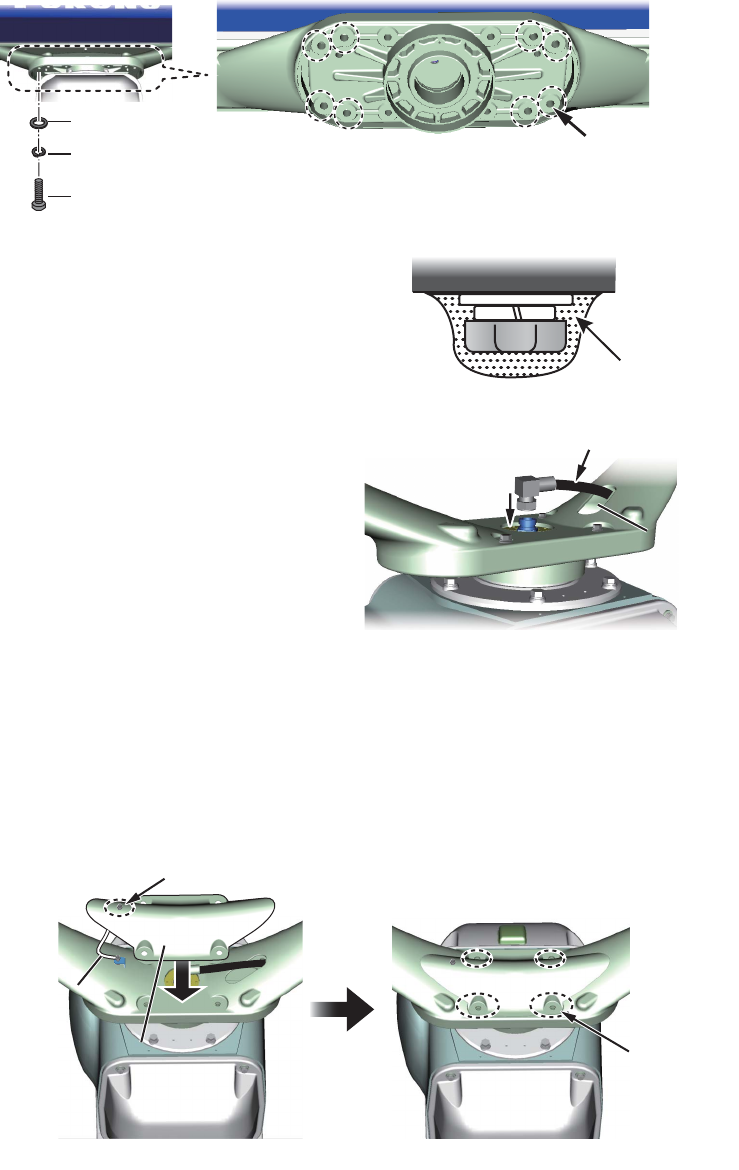
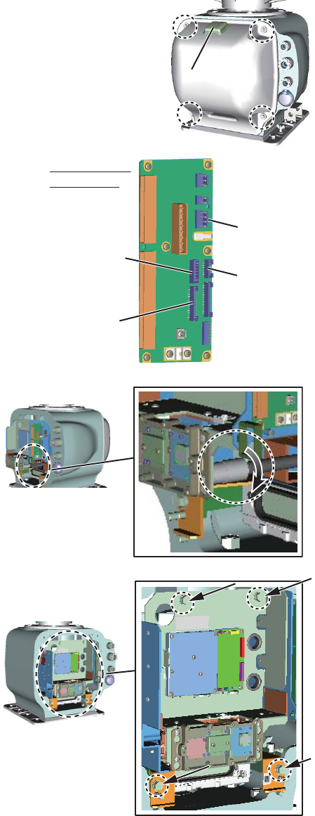
1. Loosen four bolts on the rear cover, then remove
the rear cover,
Note: The cable for the performance monitor is
connected between the rear cover and the RF-TB
Board. Detach the cover slowly to prevent damage
to the cable and connector.
2. Disconnect the performance
monitor connector (J807) and
the motor drive connectors
(J803, J804 and J840) from the
RF-TB Board.
3. Disconnect the coaxial cable.
4. Unfasten four bolts circled in
the right figure to enable remov-
al of the RF unit.
5. Remove the RF unit.
Performance monitor
Performance monitor
J807
(for performance
monitor)
J807
(for performance
monitor)
RF-TB board
(03P9570)
J804 (for motor)J804 (for motor)
J803
(for motor)
J803
(for motor)
J840
(for motor)
J840
(for motor)
Clockwise when viewed
from the stern
Clockwise when viewed
from the stern
2. WIRING
2-6
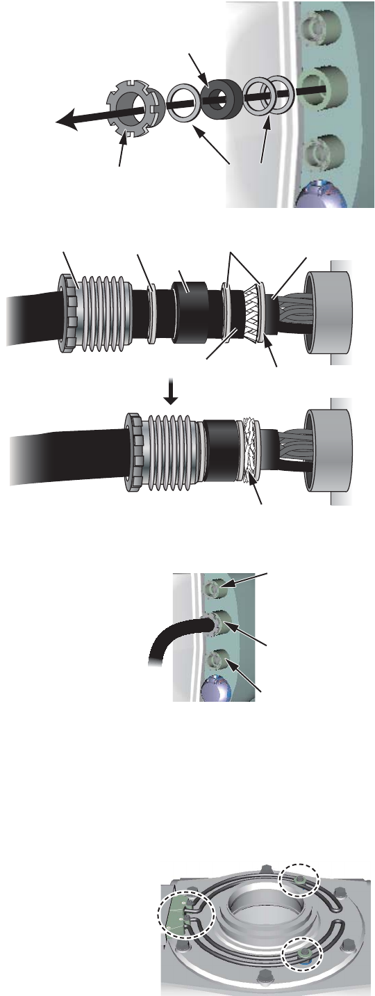
6. Unfasten the cable gland for
the antenna cable (RW-
00135) and remove the gas-
ket and three flat washers.
7. Slide the cable gland,
the gasket and three
flat washers onto the
cable as shown in the
right figure.
8. Push the flat washer
against the armor.
9. Trim the armor so that
it does not extend past
the flat washers, then
pass the antenna ca-
ble through the cable
entrance.
10. If applicable, also pass the cable for the sub
monitor and the power cable for the deicer
through the cable entrance. Pass the cables
through their respective locking wire saddle.
11. Tighten the cable glands with the hook
spanner wrench.
Note: Use the wrench of the correct size. If
you do not have the hook spanner wrench,
contact our dealer.
12. Pull the cables out of the chassis other than the cable for de-icer. See step 13 for
the deicer.
13. DE-ICER INSTALLATION. If the de-icer is not provided, go to step 14 on page 2-
8. See "S-band DE-ICER Kit Installation Instructions", issued separately, for the
de-icer not fitted at the factory.
1) Remove four bolts then spread open the
right and left heater elements on the front
cover.
Note: Lift the elements slightly when
opening so as not hit the elements on the
bolts on the chassis.
Flat washersFlat washers
GasketGasket
Gland for
antenna cable
Gland for
antenna cable
SheathSheath
Cable glandCable gland Flat washerFlat washer
GasketGasket
Flat washerFlat washer
Trim the armor.
Push the flat washer
against the armor.
Outer sheathOuter sheath
Inner sheathInner sheath
For Antenna
cable
For Antenna
cable
For Sub monitor
cable
For Sub monitor
cable
For power
cable of de-icer
For power
cable of de-icer
2. WIRING
2-7
2) Unfasten four bolts to open the front cover. Remove the cover, being careful
not to hit the elements on the chassis or radiator.
3) Remove then pass the power cable from the cable entrance. Tighten the ca-
ble gland with a hook spaner wrench.
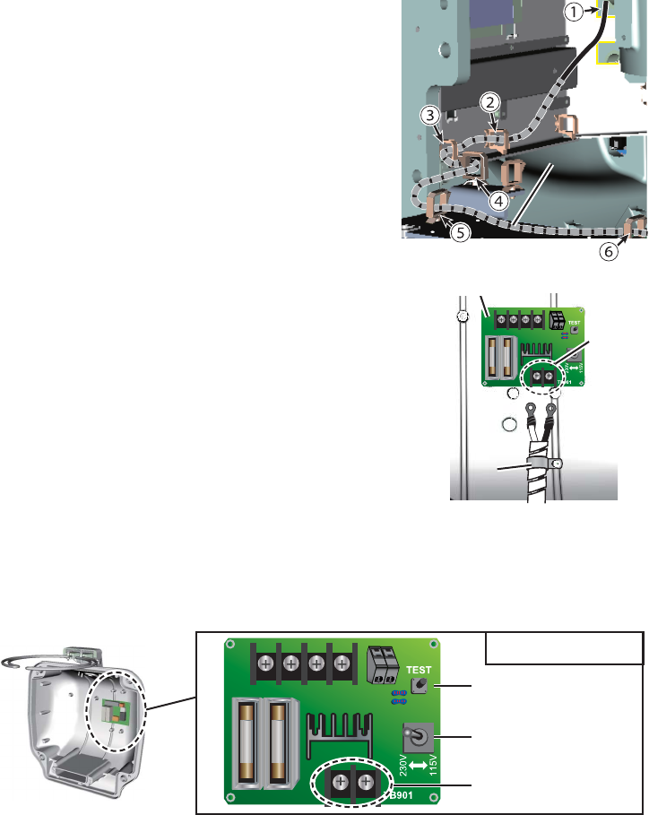
4) Wrap the supplied spiral tube around the
power cable for the de-icer, starting from the
crimp-on lugs. Set the supplied locking wire
saddle at location (6) in the right figure. Pass
the cable through locking wire saddles (1) to
(6).
5) Unfasten the cable band on the font cover.
Pass the cable for the de-icer through the band
then fasten the band. Connect the cable to TB901
on the DE-ICER board (03P9573), using the
crimp-on lugs supplied.
6) For 100-115V power supply, set the voltage selection switch to 115V. (default
setting: 230V) Turn on the power to the deicer then press the [TEST] button
about ten seconds. Check if the heater gets hot. Turn off the power to the de-
icer.
7) Fasten the front cover, then fasten the cable entrance for the DE-ICER. When
fastening the front cover, spread open the heater elements, lifting the base of
the heater. Take care not to hit the heater elements on the chassis or radiator.
Spiral tubeSpiral tube
Cable
band
Cable
band
Cable
band
Cable
band
Cable
band
03P9573
TB901
[TEST] button
[TEST] button
Voltage Selection Switch
TB901
03P9573 Board
2. WIRING
2-8
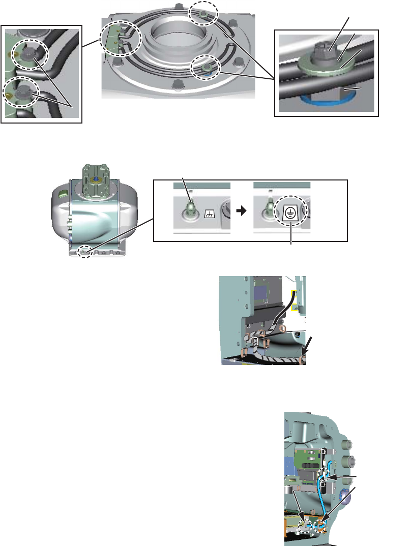
8) Fasten the two heater elements to the chassis. Fasten the base of the heater
with two M5 screws (supplied) coated with marine sealant supplied. Fasten
the installation materials to each of the cover bolts.
9) Attach the supplied earth label over the earth label attached near the ground-
ing terminal.
Note: If it is necessary to open the
front cover after installing the DE-
ICER kit, remove the power cable
from the locking wire saddle in the
right figure then detach the cover
slowly to prevent damage to the
heater.
14. Re-mount the RF unit then reconnect the connectors for the motor (J803, J840
and J804), the four bolts (see step 4) and the coaxial cable (see step 3).
15. Pass the LAN cable of the antenna cable from
the cable entrance through two locking wire
saddles to the LAN port at the bottom of the RF
unit (J821).
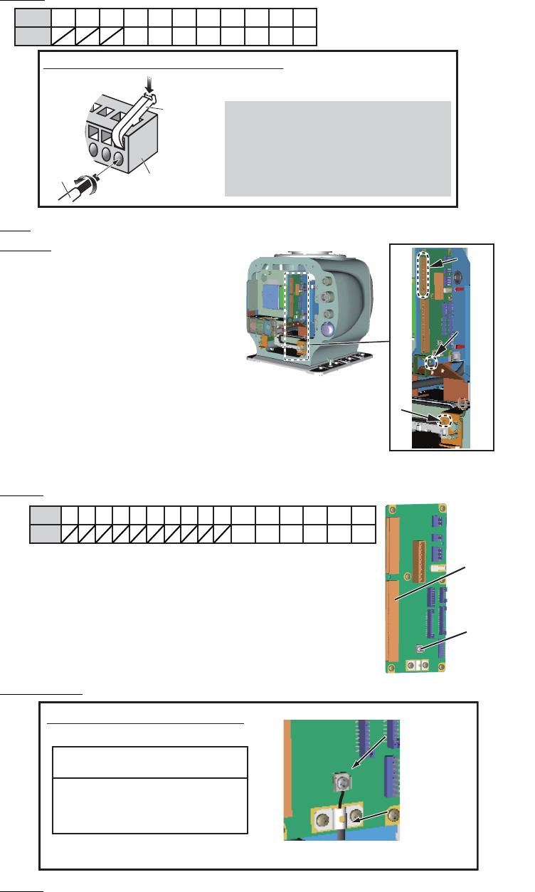
16. Attach appropriate WAGO connector (supplied) to both the antenna cable and the
cable for the sub monitor. Connect the antenna cable and the cable for the sub
monitor to the RF-TB Board as shown below. A terminal opener is provided on the
RF-TB Board.
Cover BoltCover Bolt
M5 screwM5 screw
Fixing Shaft Fixing Shaft
SD Heater
Fixing Plate
SD Heater
Fixing Plate
M5 screw coated with marine sealantM5 screw coated with marine sealant
Grounding terminalGrounding terminal
Earth label
Remove the power
cable from the
locking wire saddle to
open the front cover.
Remove the power
cable from the
locking wire saddle to
open the front cover.
Locking
wire
saddles
Locking
wire
saddles
LAN portLAN port
2. WIRING
2-9
• Antenna cable:
Power: TB801 on RF-TB Board (03P9570)
LAN: J821 on RF-TB board
Shields: For the power cable,
screw on RF-TB Board
(03P9570).
For the LAN cable, screw near
the LAN slot.
For the antenna cable RW-9600,
connect the crimp-on lug (that
binds unused wires) together
with the shield of the power ca-
ble.
• Cable for sub monitor:
Signal: TB803 on RF-TB board
Coax. cable: TB804 on RF-TB board
Shield: Screw on chassis.
17. Reconnect the performance monitor connector (J807), see step 2 on page 2-5.
18. Check that the gasket on the rear cover is seated properly, then close the covers.
The torque must be 21.0 N•m.
Wire
How to connect wires to WAGO connector
Press downward.
Terminal
opener
WAGO
connector
Twist
<Procedure>
1. Twist the cores.
2. Press the terminal opener downward.
3. Insert the wire to hole.
4. Remove the terminal opener.
5. Pull the wire to confirm that it is secure.
1 3 6789 11245 10
BRN RED ORG YEL GRN BLU PPL WHT
Pin
Color
Grounding
point for
Power cable
Grounding
point for
Power cable
Grounding point for
LAN cable
Grounding point for
LAN cable
TB801TB801
TB803
TB803
TB804
TB804
13 6789
11 12 13 14 15 16
245 10
BRN RED ORG YEL BLKWHT
Pin
Color
How to fasten the coaxial cable
NOTICE
Do not use crimp-on lug, to
prevent contact resistance
from increasing.
Fasten shield with clamp.Fasten shield with clamp.
Fasten
conductor with
screw.
Fasten
conductor with
screw.