Furuno Fax 210 F User Manual To The 4cce1420 65b2 4175 A072 Cc278c570b95
User Manual: Furuno Fax-210 to the manual
Open the PDF directly: View PDF ![]() .
.
Page Count: 100
- SAFETY INSTRUCTIONS
- FOREWORD
- FEATURES
- TABLE OF CONTENTS
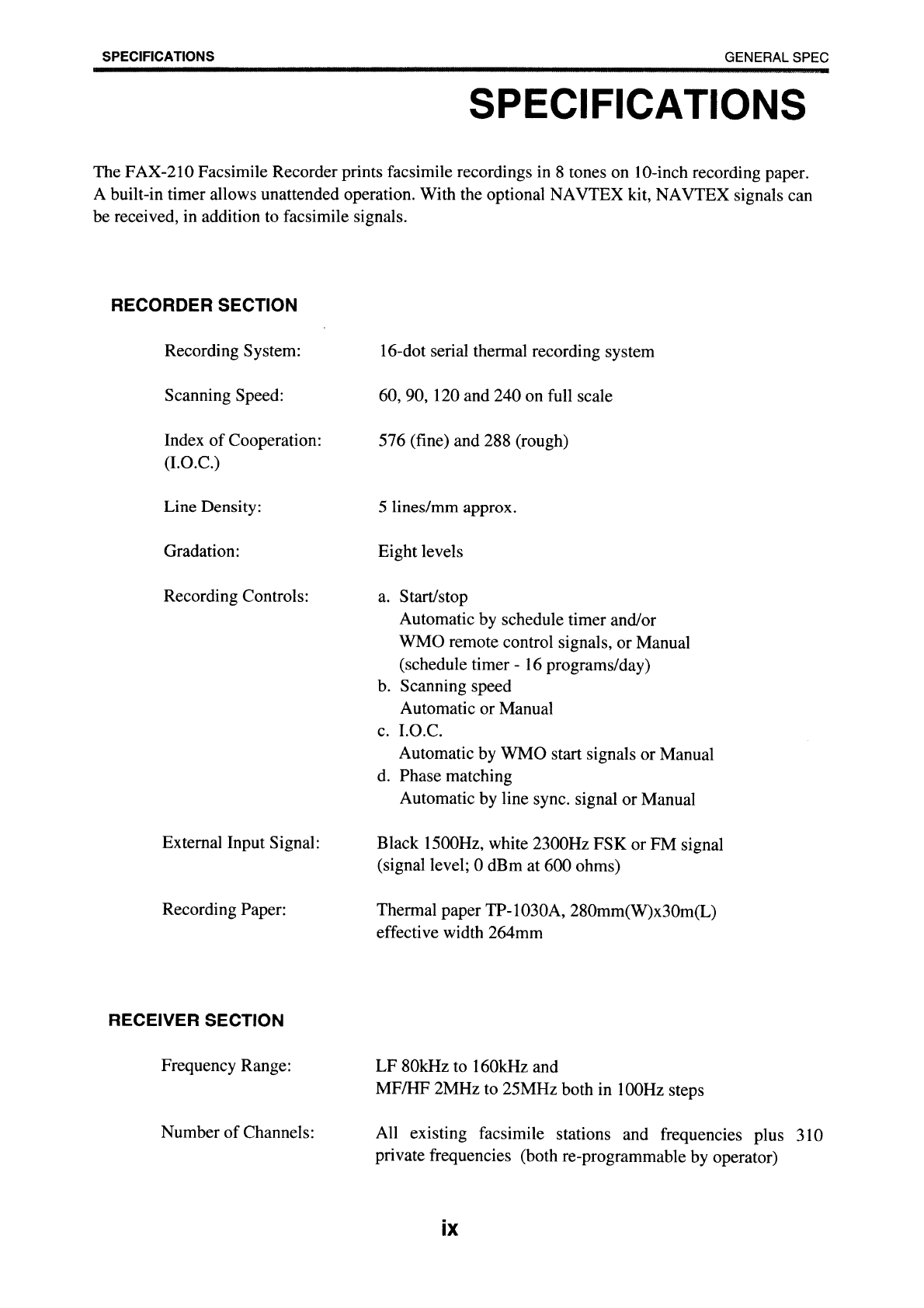
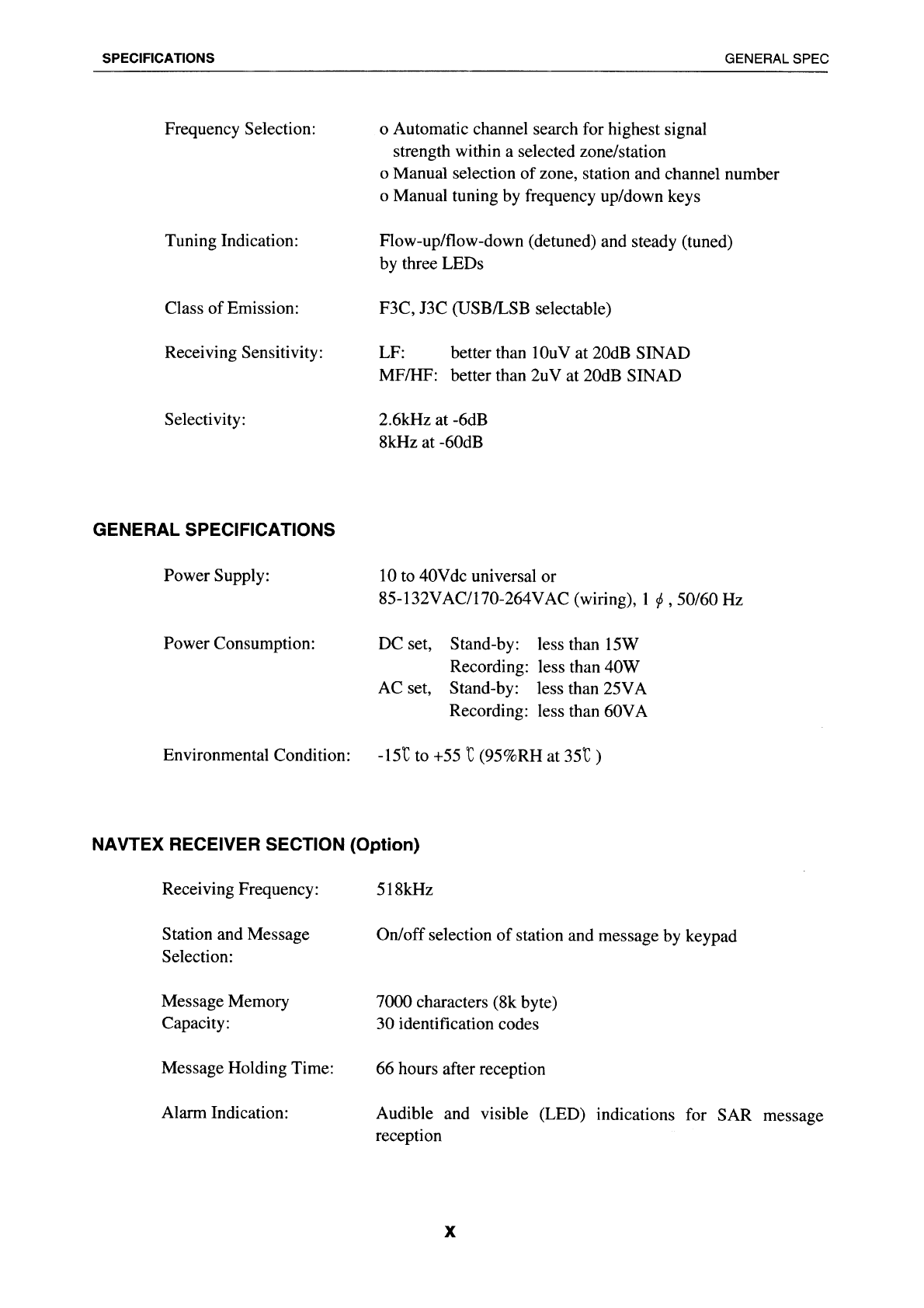
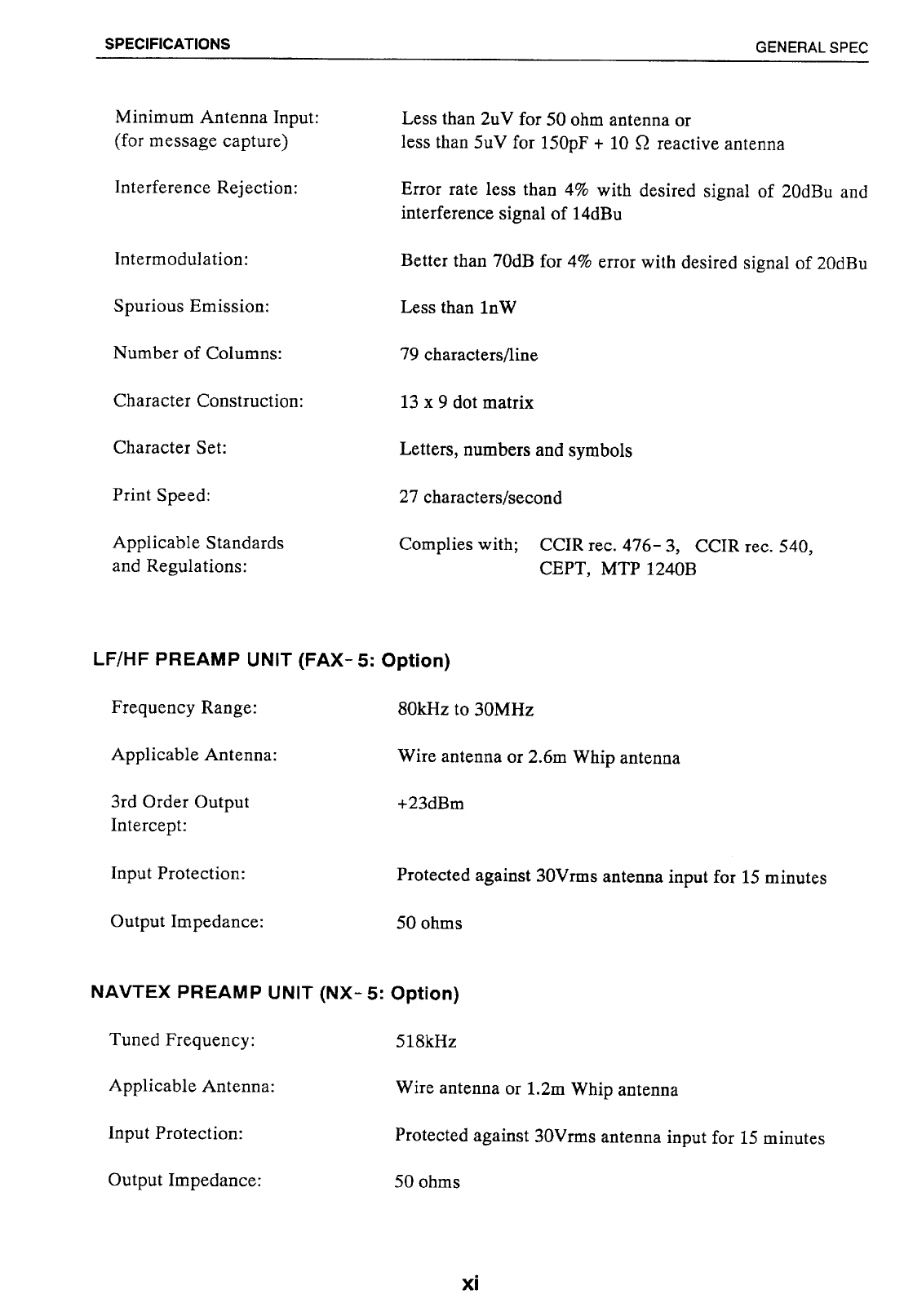
- SPECIFICATIONS
- CHAPTER 1 OPERATION
- CHAPTER 2 MAINTENANCE
- CHAPTER 3 TROUBLESHOOTING
- CHAPTER 4 INSTLLATION
- APPENDIX-A PRINCIPLE OF FACSIMILE AND NAVTEX SYSTEMS
- APPENDIX-B MAPS & LISTS
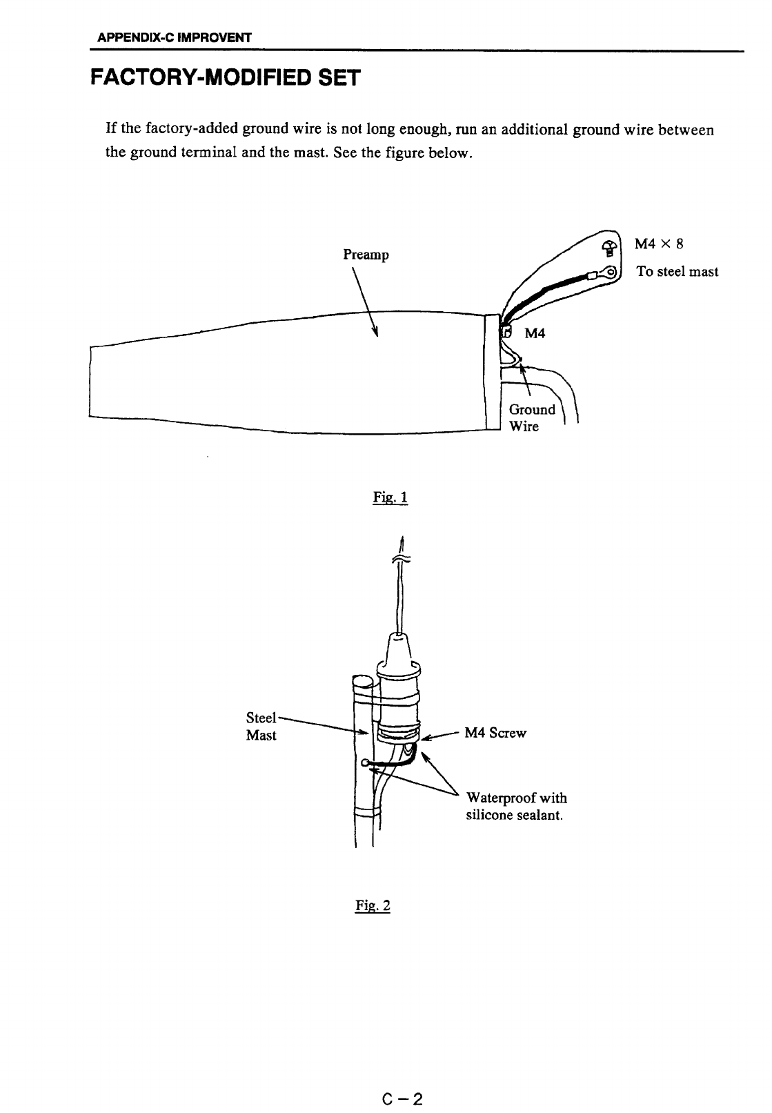
- APPENDIX-C IMPROVEMENT OF RECEIVER S/N RATIO(Remedy for RFI)
- LISTS
- OUTLINE DRAWINGS
- INTERCONNECTION DIAGRAM
- Declaration of Conformity
Back

Your Local Agent/DealerYour Local Agent/Dealer
9-52 Ashihara-cho,9-52 Ashihara-cho,
Nishinomi
y
a 662-8580, JAPANNishinomi
y
a 662-8580, JAPAN
Tele
p
hone :Tele
p
hone : 0798-65-21110798-65-2111
FaxFax 0798-65-42000798-65-4200
::
F
IRST EDITION :
F
IRST EDITION :NOVNOV.. 19911991
Printed in JapanPrinted in Japan
A
ll ri
g
hts reserved.
A
ll ri
g
hts reserved.
M1M1 ::AUGAUG.. 06, 200406, 2004
Pub. No.Pub. No. OME-62490OME-62490
*
00080289300
*
*
00080289300
*
*
00080289300
*
*
00080289300
*
(( YOSHYOSH )) FAX-210FAX-210 * 0 0 0 8 0 2 8 9 3 0 0 ** 0 0 0 8 0 2 8 9 3 0 0 *
*
OME
62490
M
10
*
*
OME
62490
M
10
*
*
OME
62490
M
10
*
*
OME
62490
M
10
*
* O M E 6 2 4 9 0 M 1 0 ** O M E 6 2 4 9 0 M 1 0 *

ii
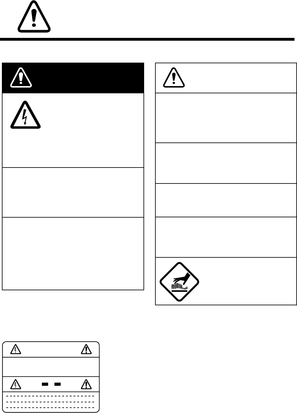
SAFETY INFORMATION
FOR THE OPERATOR
Avoid opening cover of
equipment except to
replace paper, fuse or print-
ing head.
Do not touch printing head
just after printing.
Burn can result.
This equipment uses high
voltage electricity which can
shock.
WARNING
Do not dissasemble or modify the
equipment.
Fire, electrical shock or serious injury can
result.
Use the correct fuse.
Use of the wrong fuse can cause fire or
equipment damage.
Do not operate the unit with wet hands.
Electrical shock can result.
Do not place heater near the equipment.
Heat can melt the power cord, which can
result in fire or electrical shock.
Do not place liquid-filled containers on
the top of the equipment.
Fire or electrical shock can result if a liquid
spills into the equipment.
Immediately turn off the power at the
ship's mains switchboard if water or
foreign object falls into the equipment
or the equipment is emitting smoke or
fire.
Continued use of the equipment can cause
fire, electrical shock or serious injury.
CAUTION
WARNING Label attached
WARNING
To avoid electrical shock, do not
remove cover. No user-serviceable
parts inside.
Name: Warning Label (1)
Type: 86-003-1011-0
Code No. : 100-236-230
iii
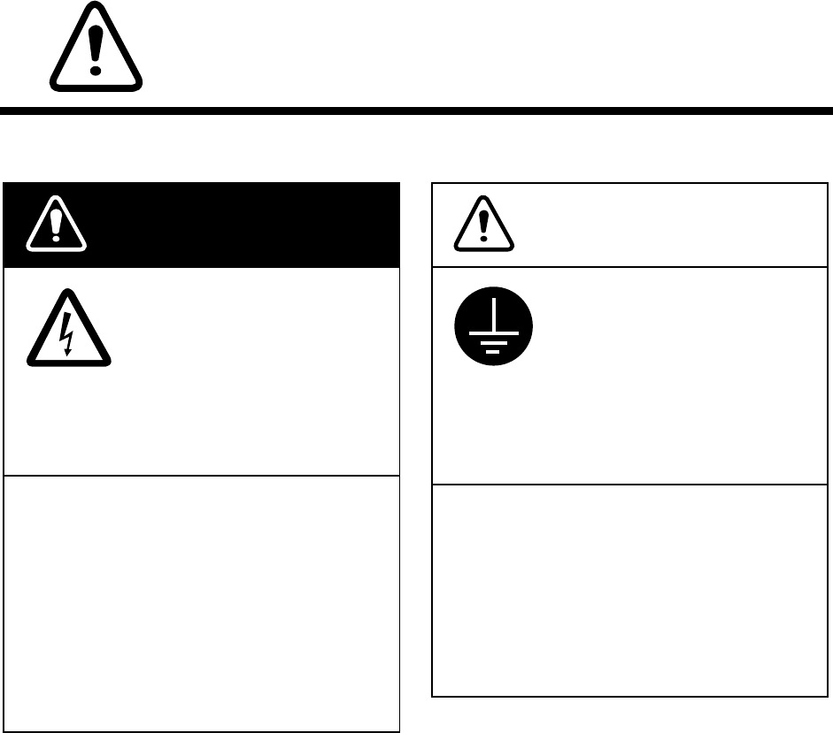
SAFETY INFORMATION
FOR THE INSTALLER
Only qualified personnel
should work inside the
equipment.
Ground the equipment to
prevent electrical shock
and mutual interference.
Ungrounded equipment can
give off or receive electro-
magnetic interference or
cause electrical schock.
This equipment uses high
voltage electricity which can
shock, burn, or cause death.
WARNING
Turn off the power at the ship's mains
switchboard before beginning the
installation. Post a warning sign near
the switchboard to ensure that the
power will not be applied while the
equipment is being installed.
Serious injury or death can result if the
power is not turned off, or is applied while
the equipment is being installed.
Confirm that the power supply voltage
is compatible with the voltage rating
of the equipment.
Connection to the wrong power supply
can cause fire or equipment damage. The
voltage rating appears on the label at the
rear of the equipment.
CAUTION


vii
page
CHAPTER 2 MAINTENANCE........................... 2-1 to 2-8
GENERAL MAINTENANCE ................................................................................ 2-1
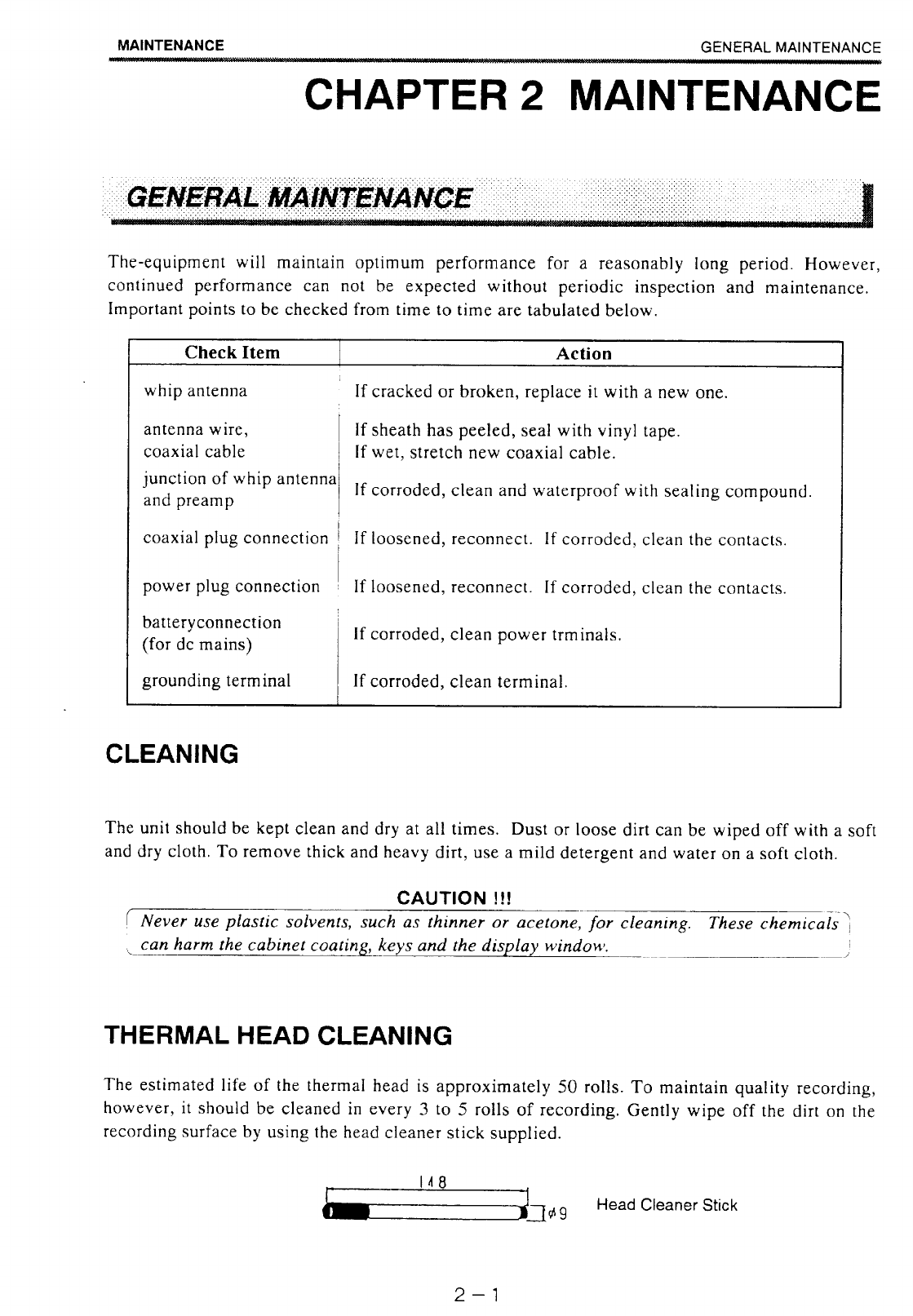
Cleaning............................................................................................................2-1
Thermal Head Cleaning.................................................................................... 2-1
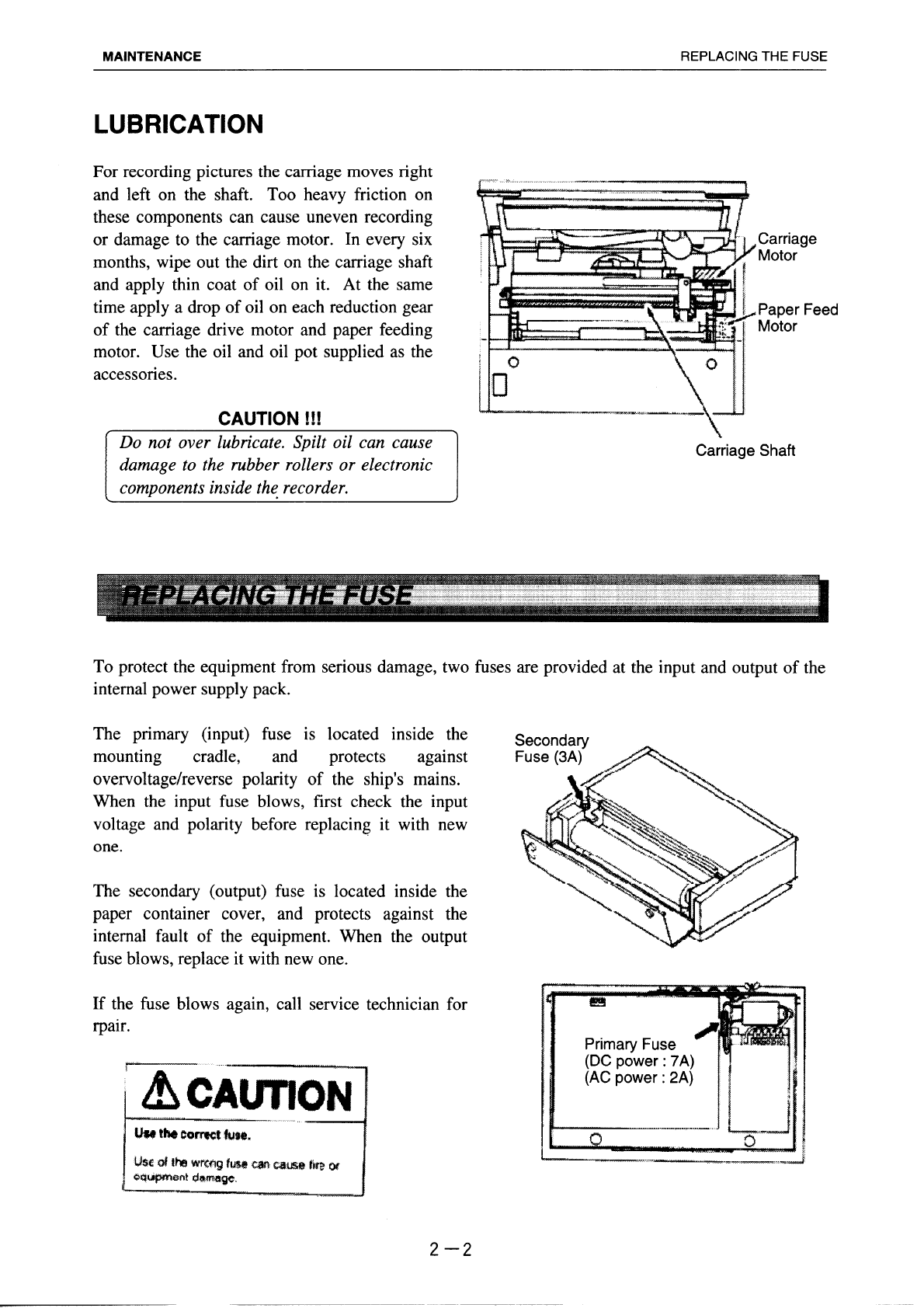
Lubrication......................................................................................................... 2-2
REPLACING THE FUSE .....................................................................................2-2
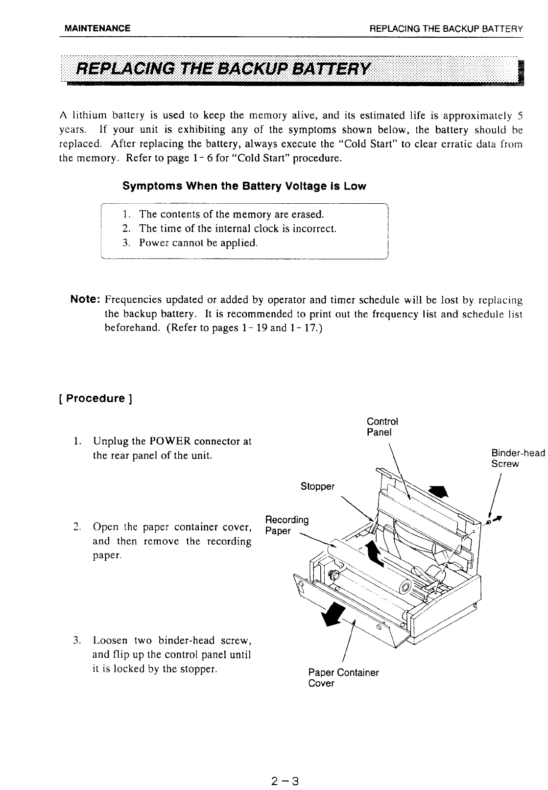
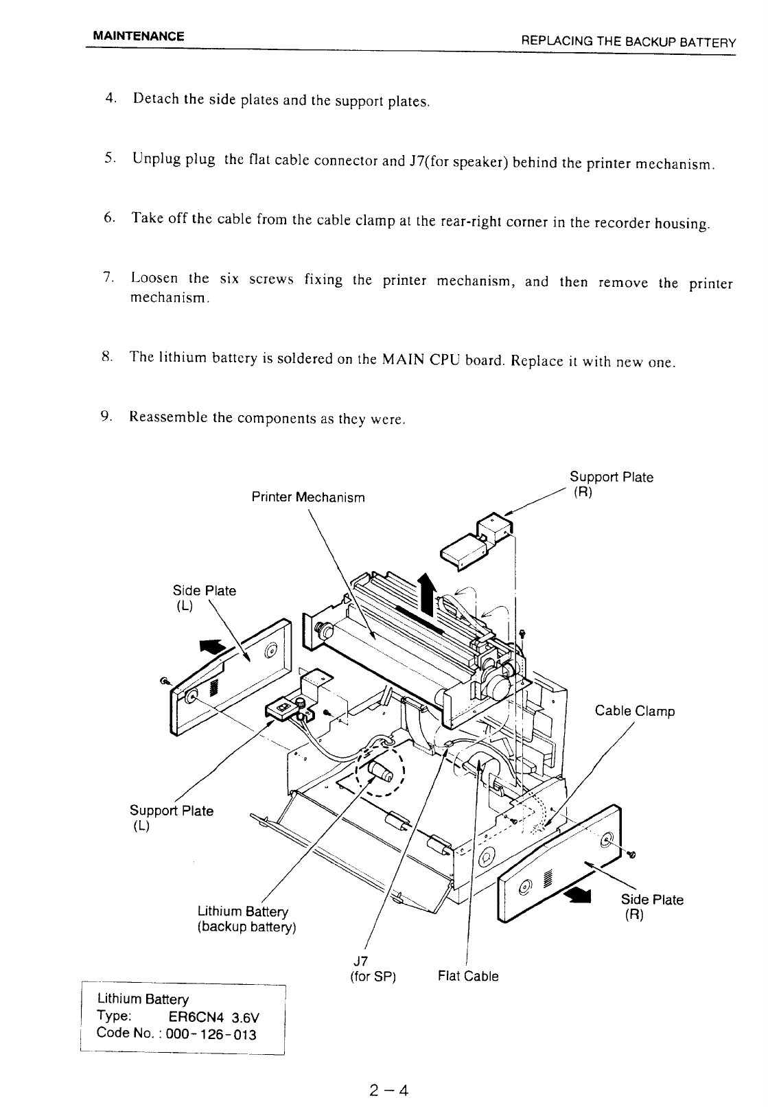
REPLACING THE BACKUP BATTERY .............................................................2-3
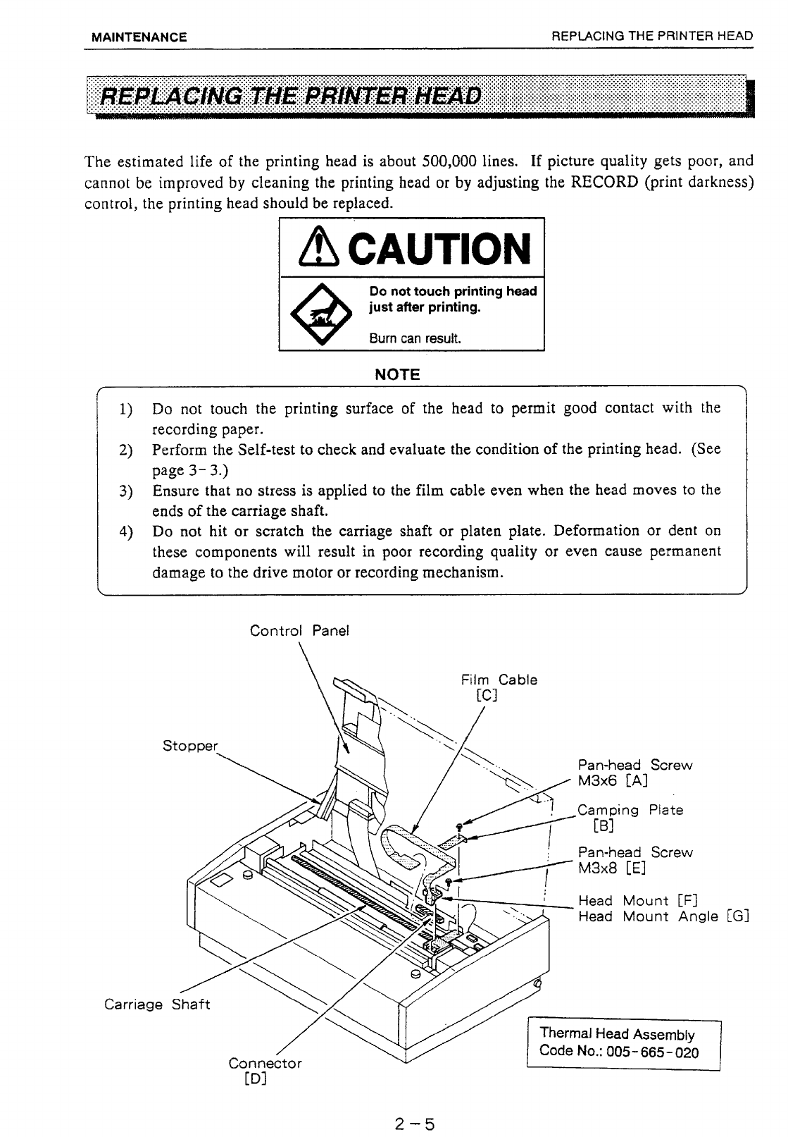
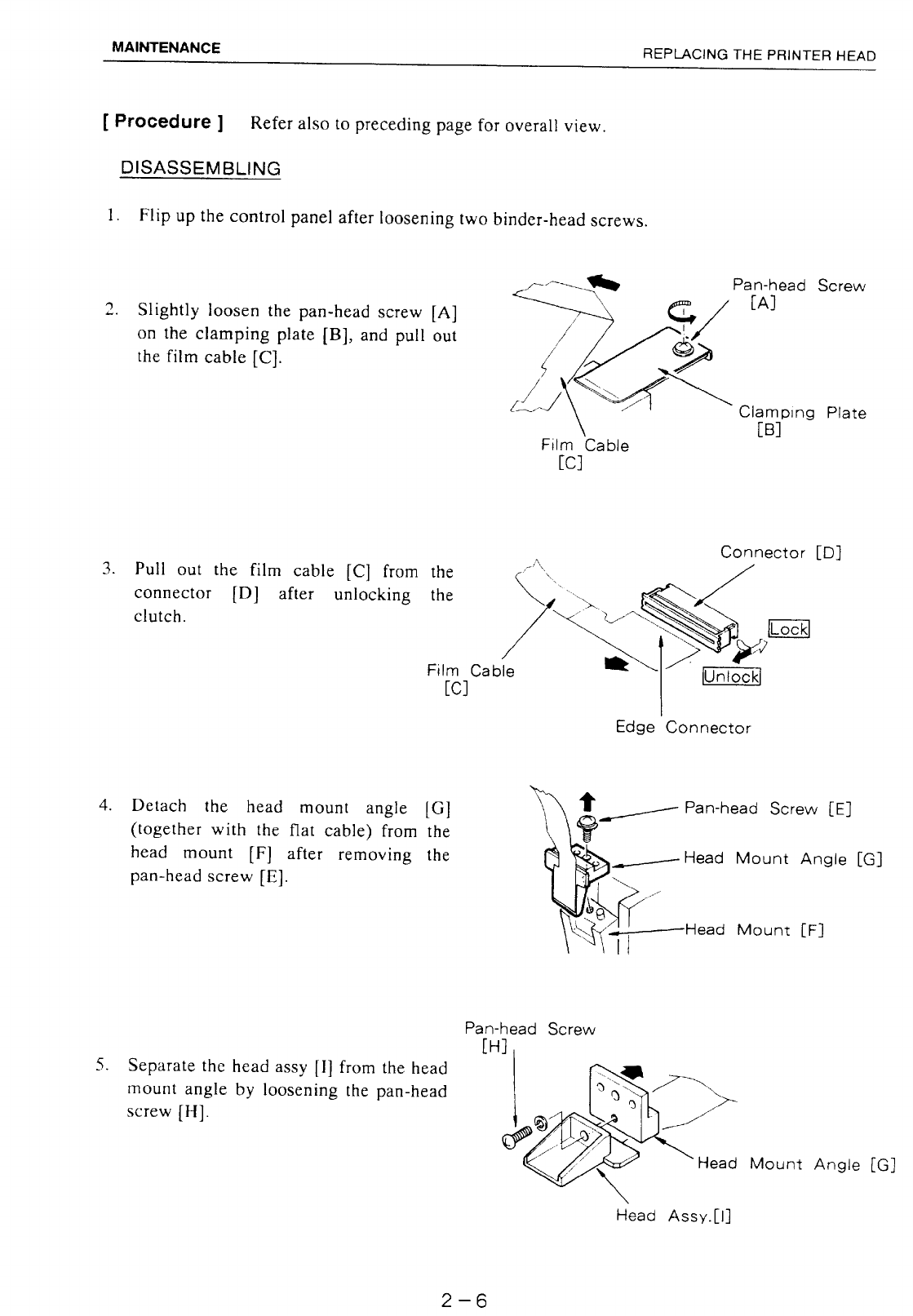
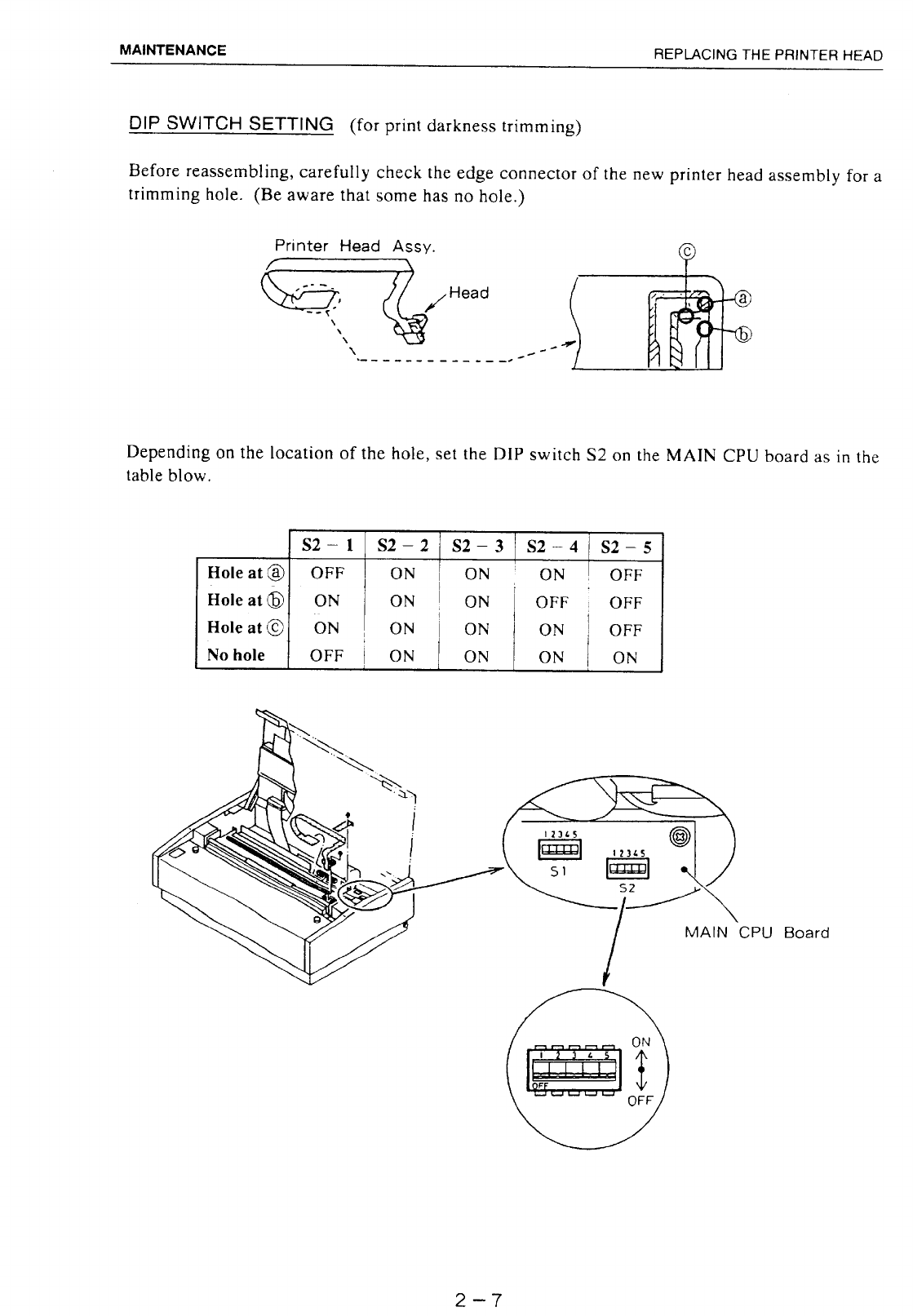
REPLACING THE PRINTER HEAD....................................................................2-5
CHAPTER 3 TROUBLESHOOTING ............................3-1 to 3-4
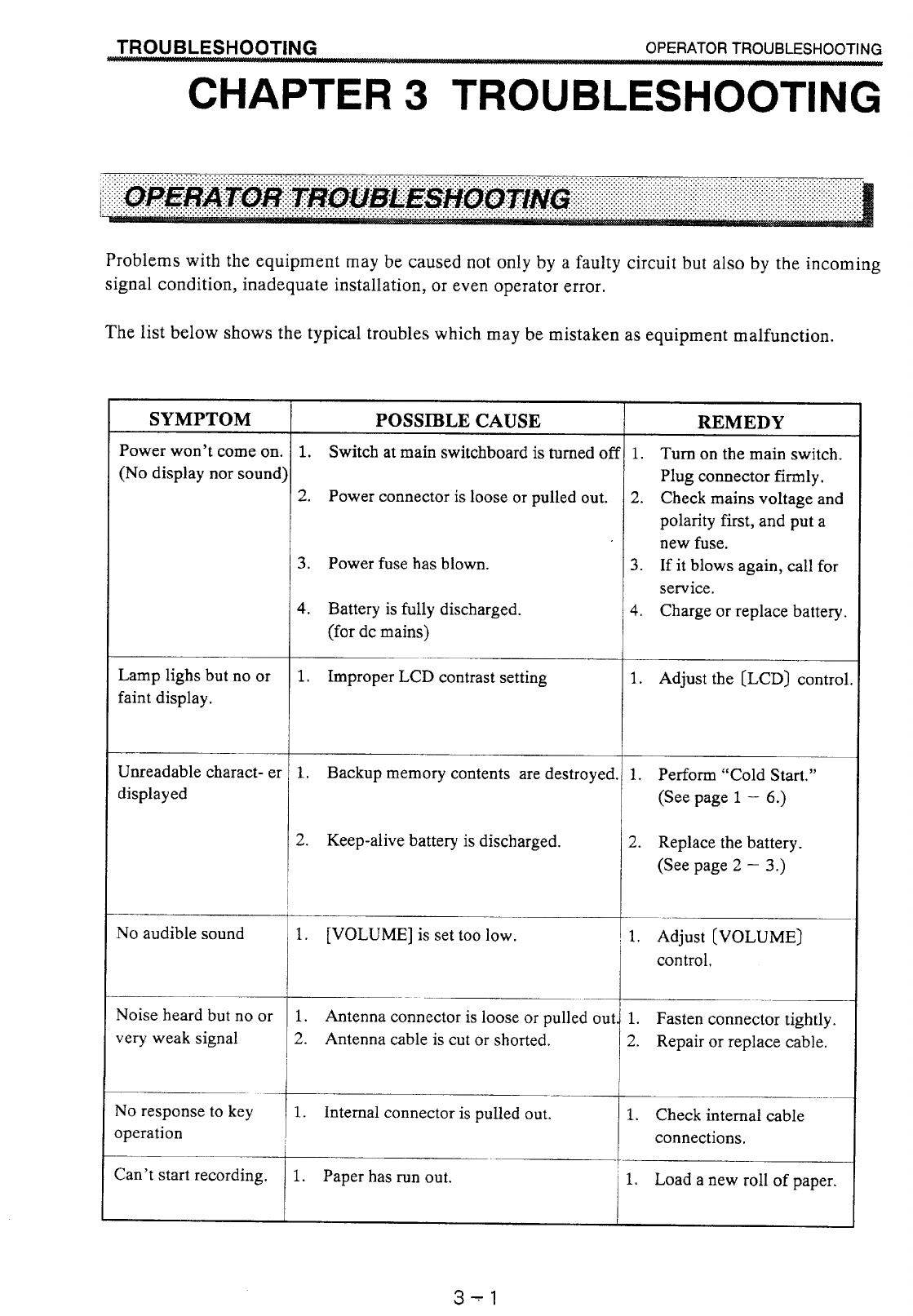
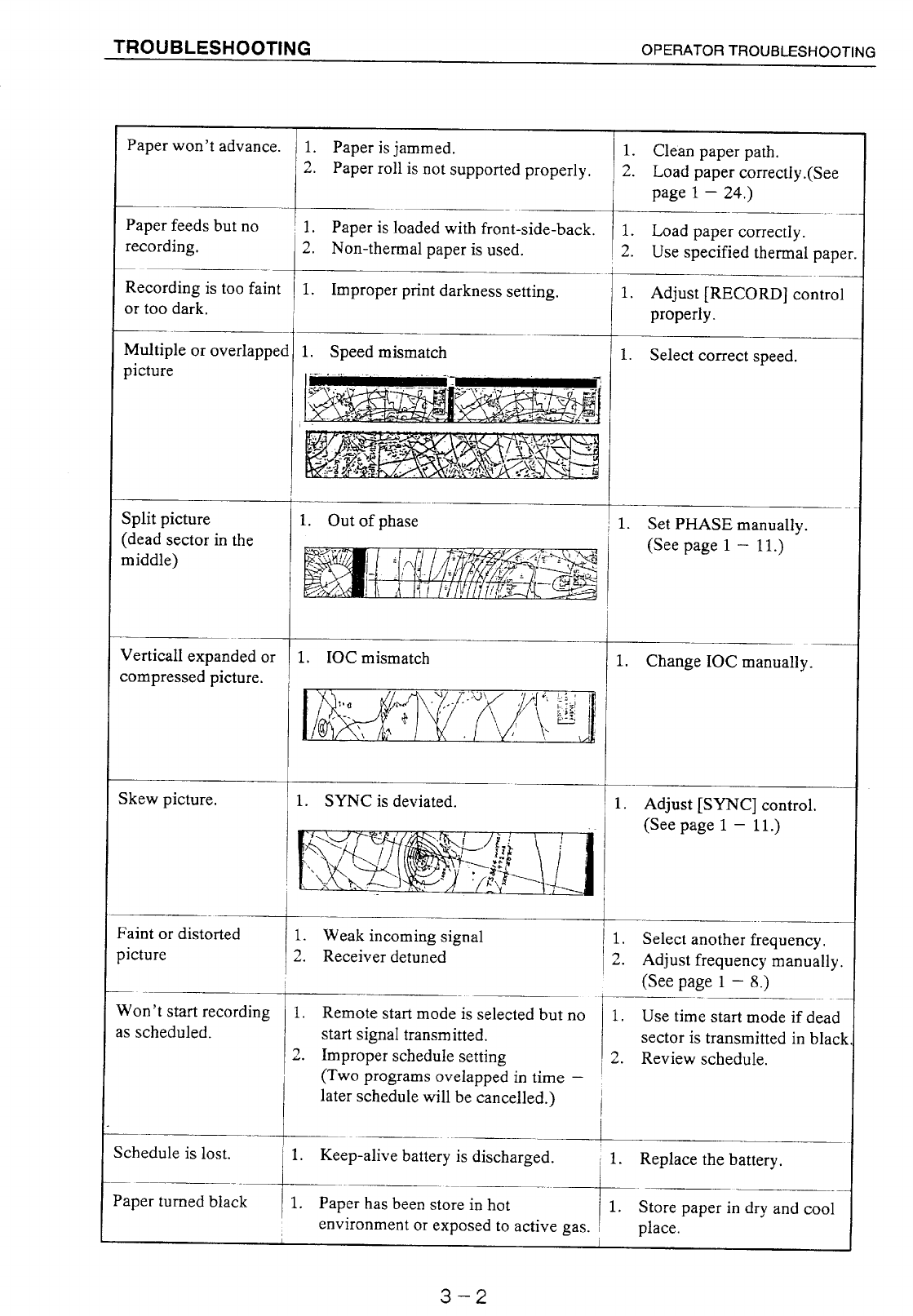
OPERATOR TROUBLESHOOTING ...................................................................3-1
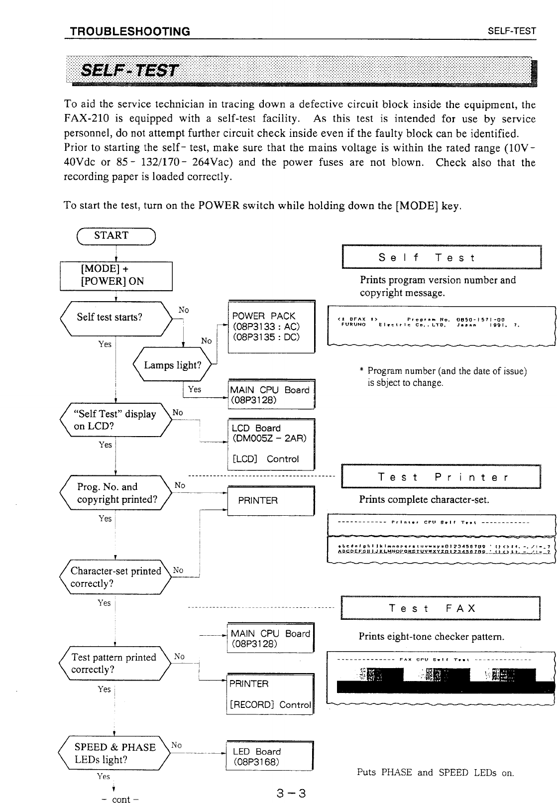
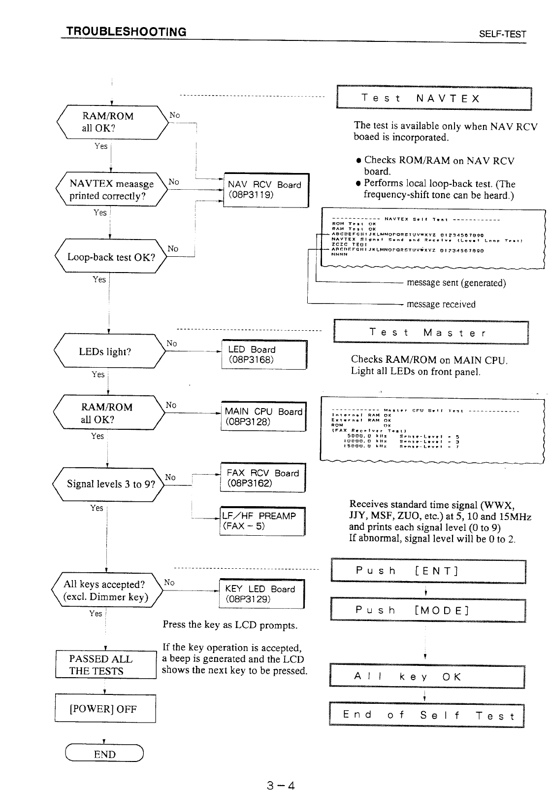
SELF-TEST ..........................................................................................................3-3
CHAPTER 4 INSTALLATION.....................................4-1 to 4-17
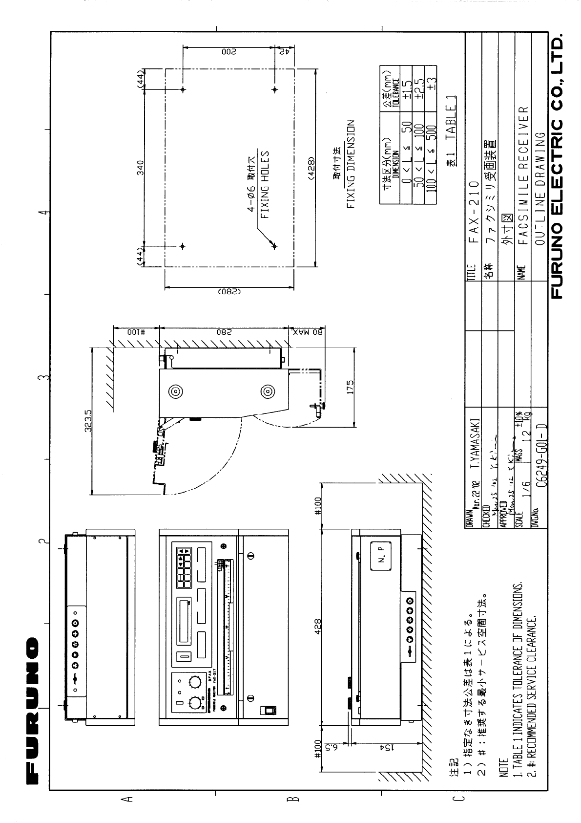
RECORDER UNIT INSTALLATION .................................................................... 4-1
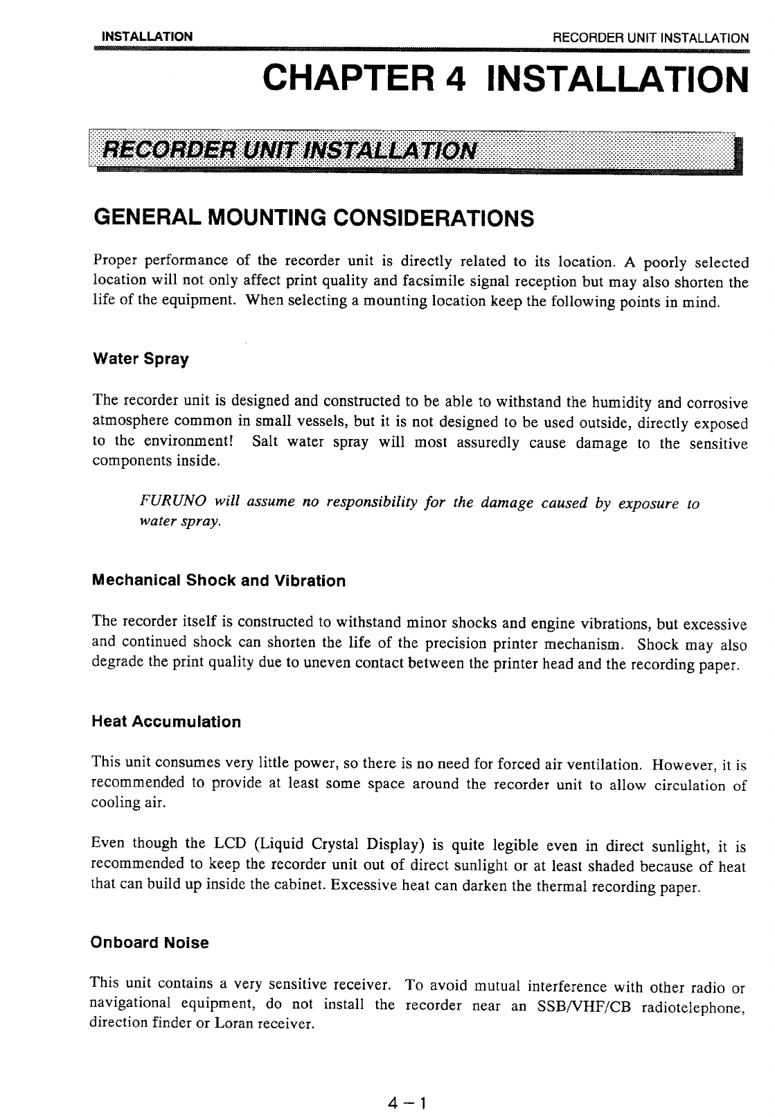
General Mounting Considerations....................................................................4-1
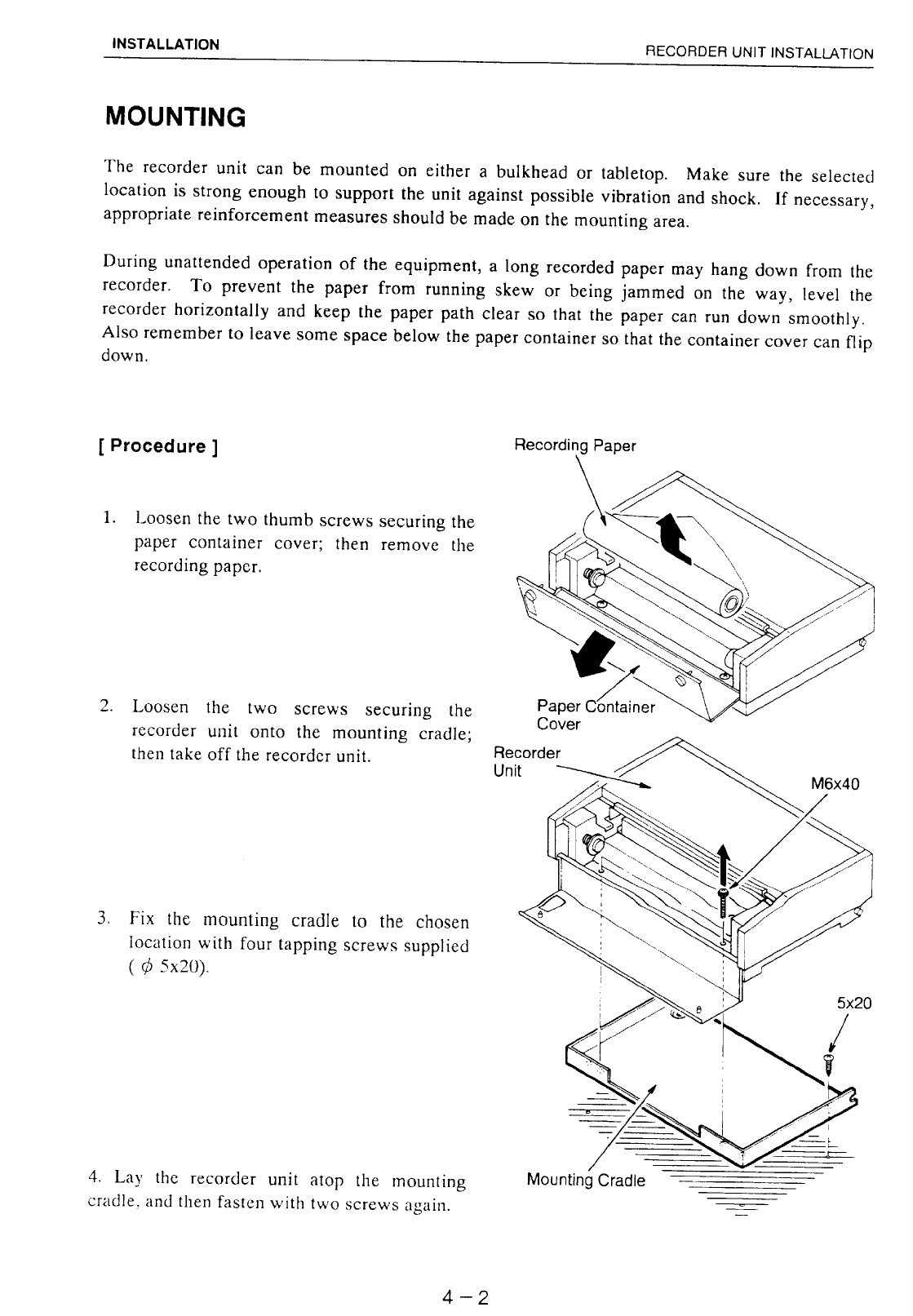
Mounting ...........................................................................................................4-2
ANTENNA INSTALLATION.................................................................................4-4
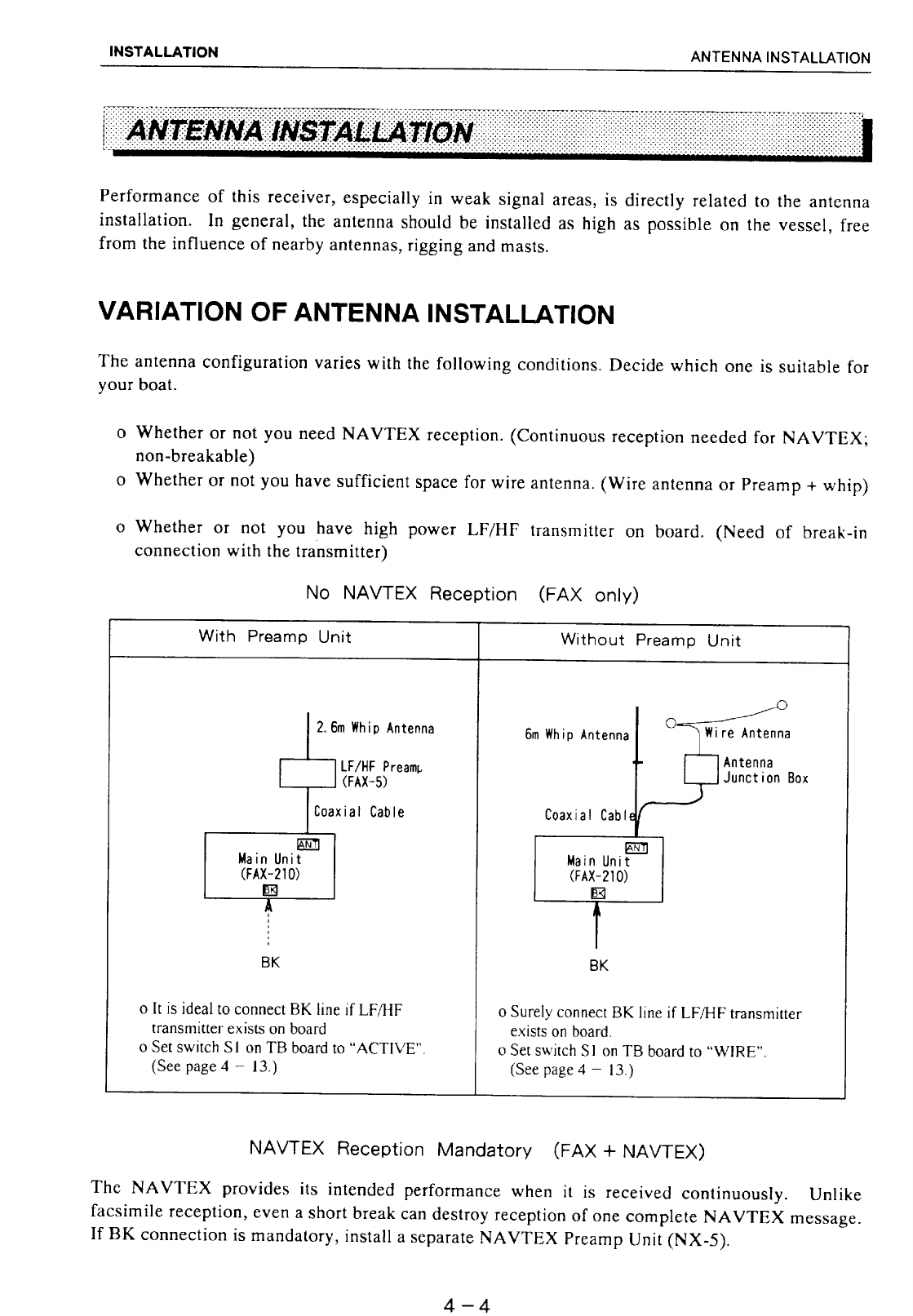
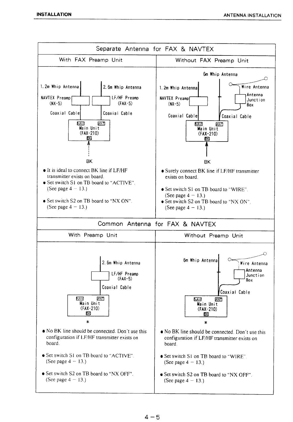
Variation of Antenna Installation .......................................................................4-4
Passive Antenna ...............................................................................................4-6
Active Antenna..................................................................................................4-6
CABLE CONNECTIONS .....................................................................................4-7
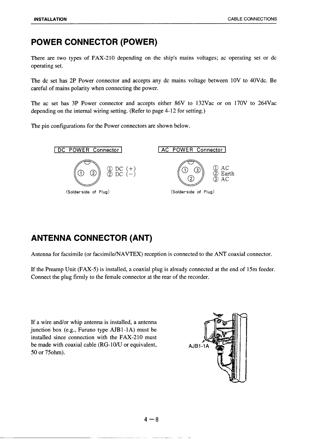
Power Connector.............................................................................................. 4-8
Antenna Connector...........................................................................................4-8
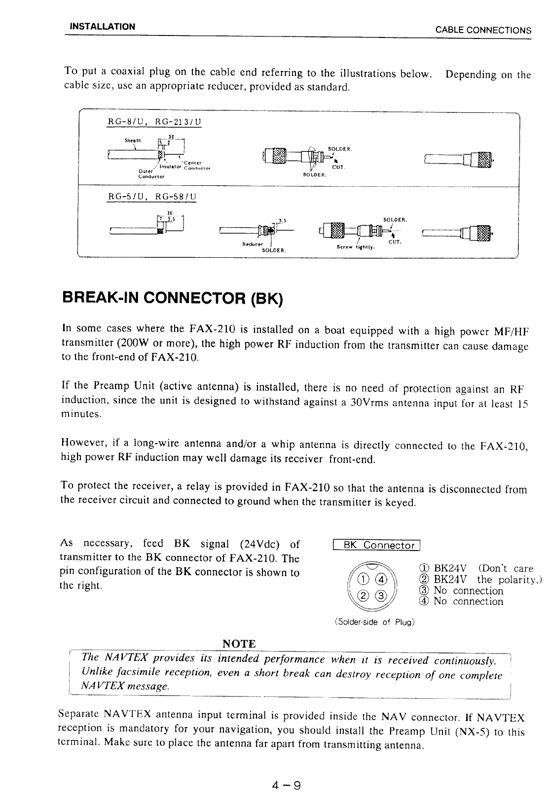
Break-in Connector...........................................................................................4-9
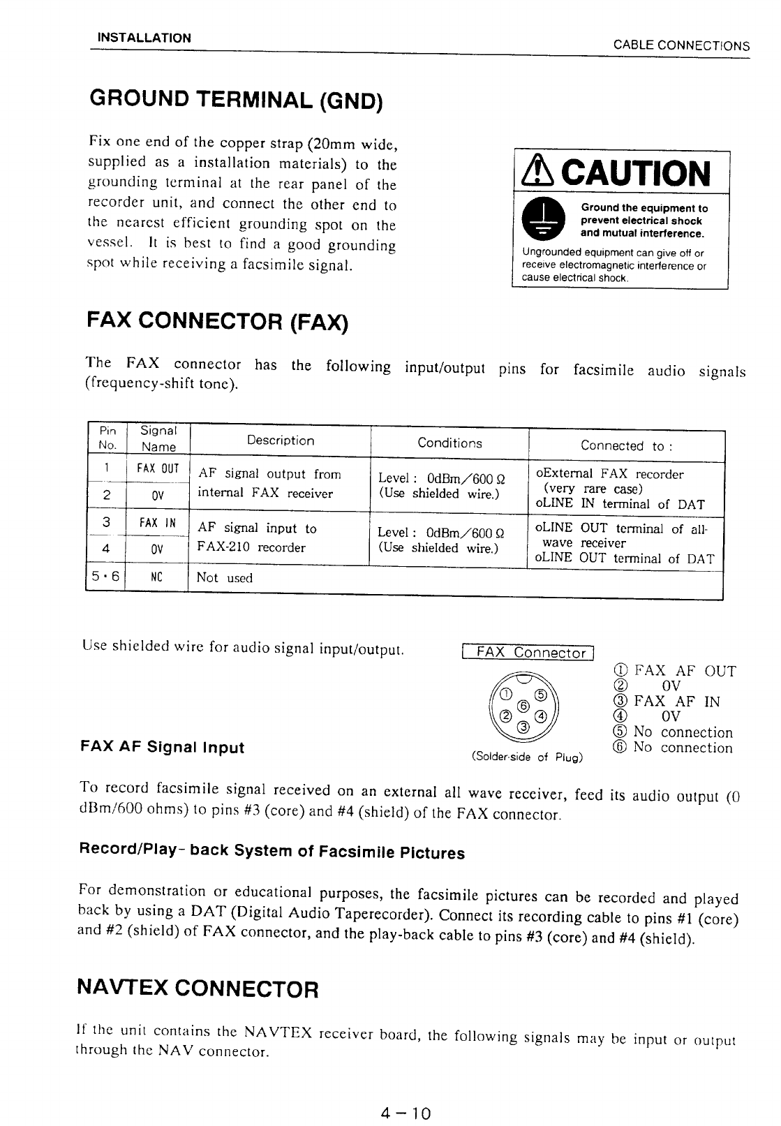
Ground Terminal .............................................................................................4-10
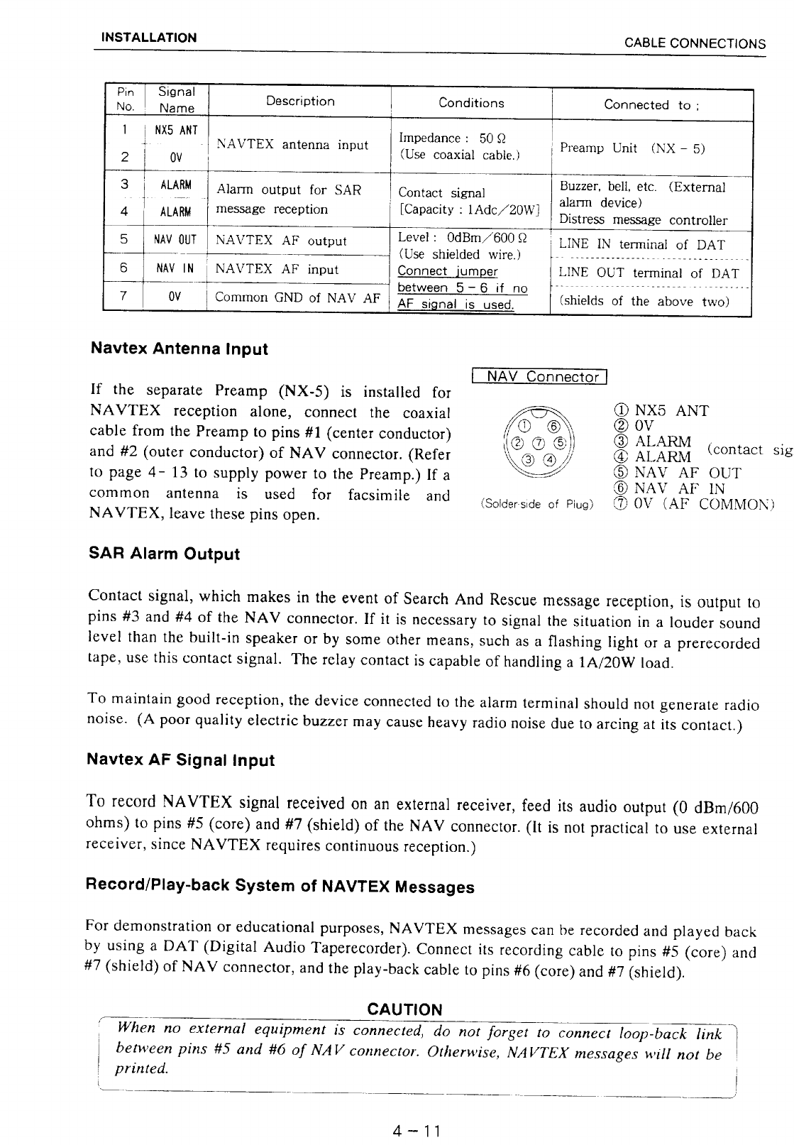
NAVTEX Connector........................................................................................4-10
PRESETS AFTER INSTALLATION ..................................................................4-12
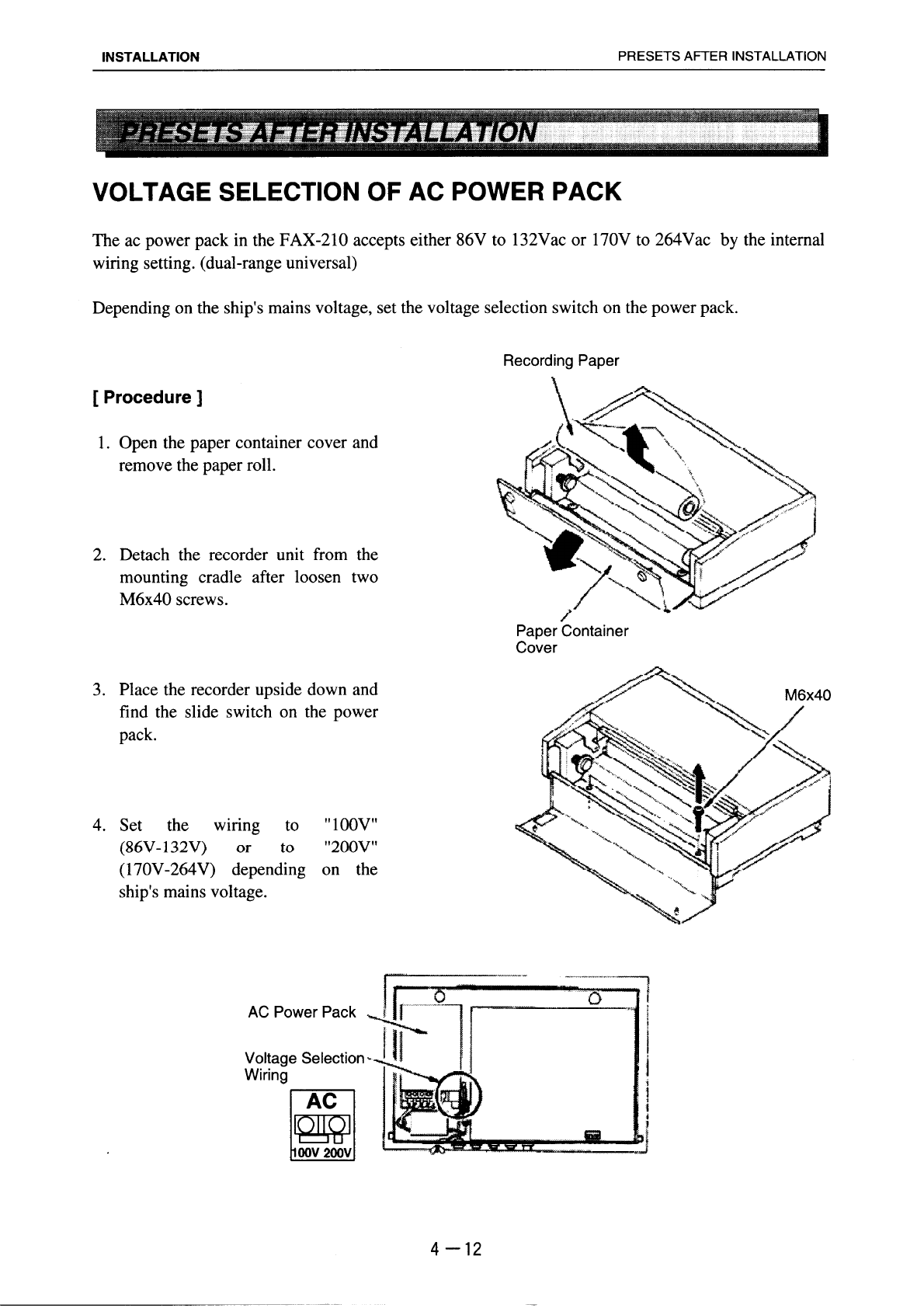
Voltage Selection of AC Power Pack .............................................................4-12
Preset for Preamp Unit ...................................................................................4-13
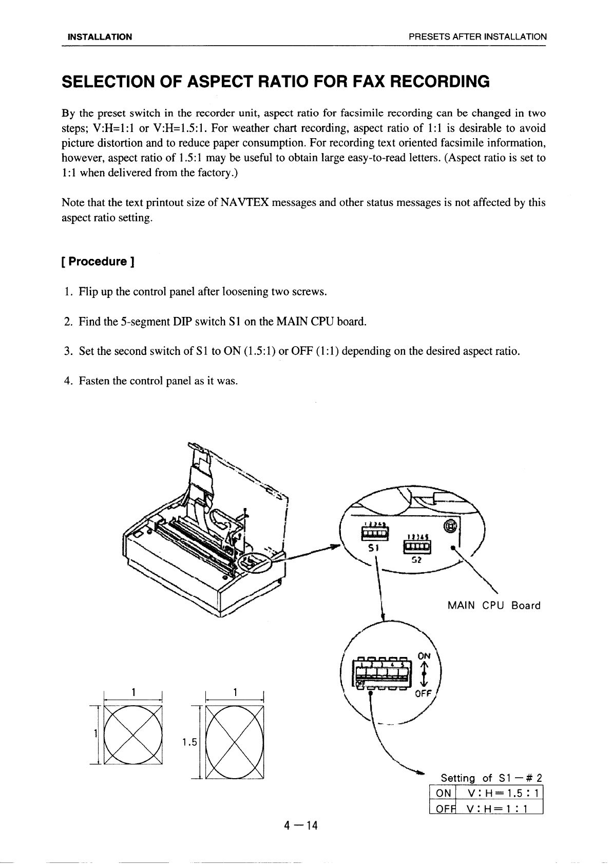
Selection of Aspect Ratio for FAX Recording.................................................4-14
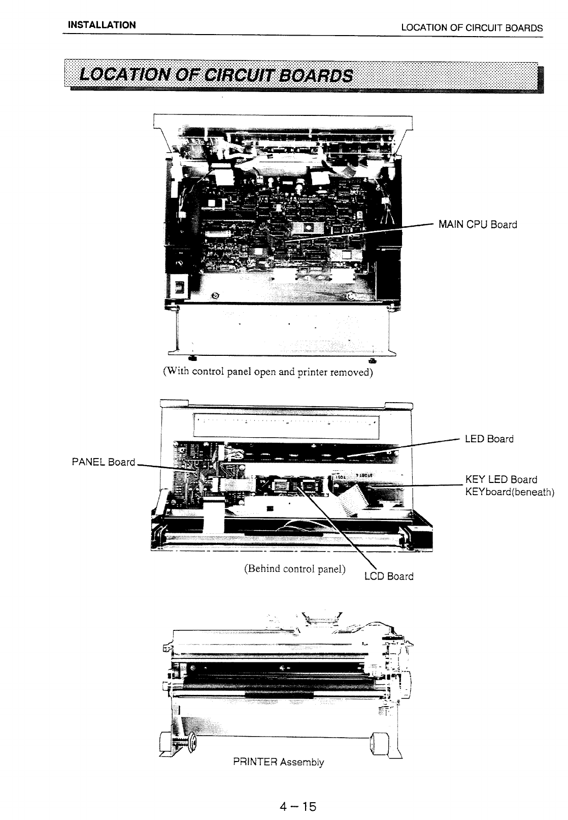
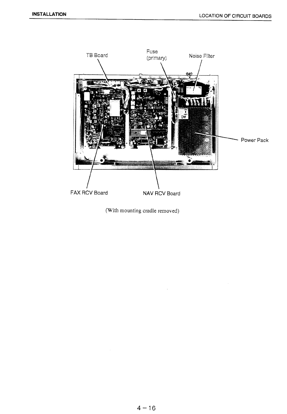
LOCATION OF CIRCUIT BOARDS ..................................................................4-15
TAPING WHIP ANTENNA .................................................................................4-17

viii
page
APPENDIX A PRINCIPLE OF FACSIMLE AND
NAVTEX SYSTEMS............................ A-1 to A-6
HOW A FACSIMLE SYSTEM WORKS ........................................................... A-1
Radio Facsimile System ................................................................................A-1
Recording System on the FAX-210 ...............................................................A-3
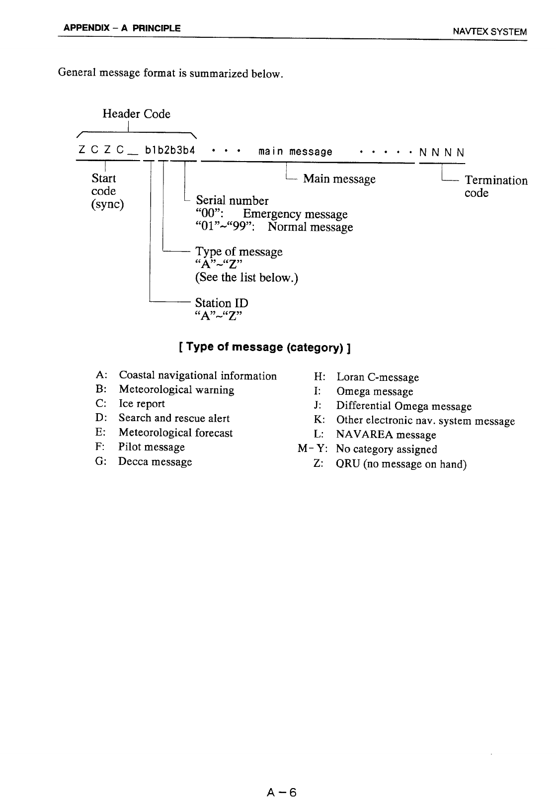
HOW NAVTEX WORKS .................................................................................. A-4
NAVTEX System Operation...........................................................................A-4
Message Format............................................................................................A-5
APPENDIX B MAPS & LISTS ...................................B-1 to B-9
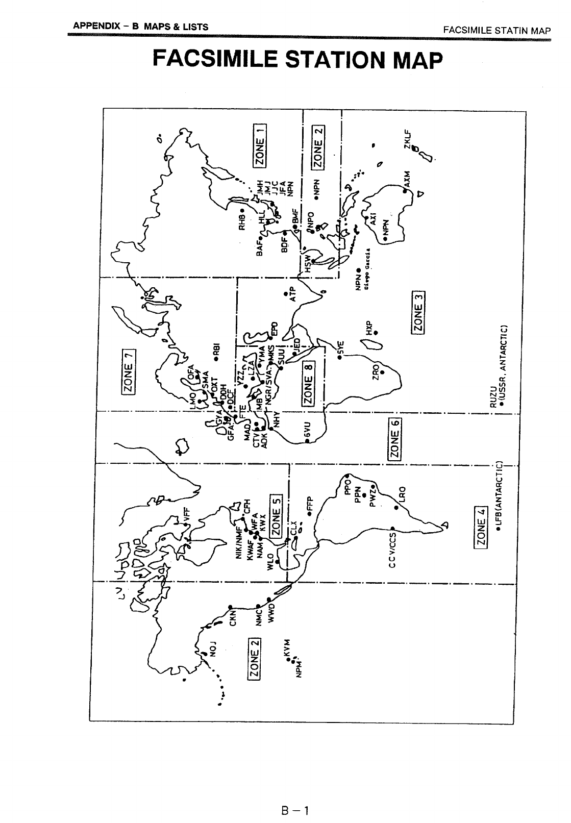
Facsimile Station Map ...................................................................................B-1
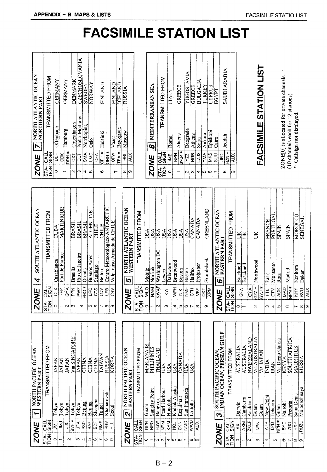
Facsimile Station List.....................................................................................B-2
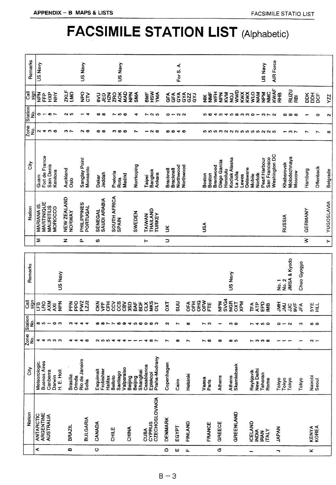
Facsimile Station List (Alphabetic).................................................................B-3
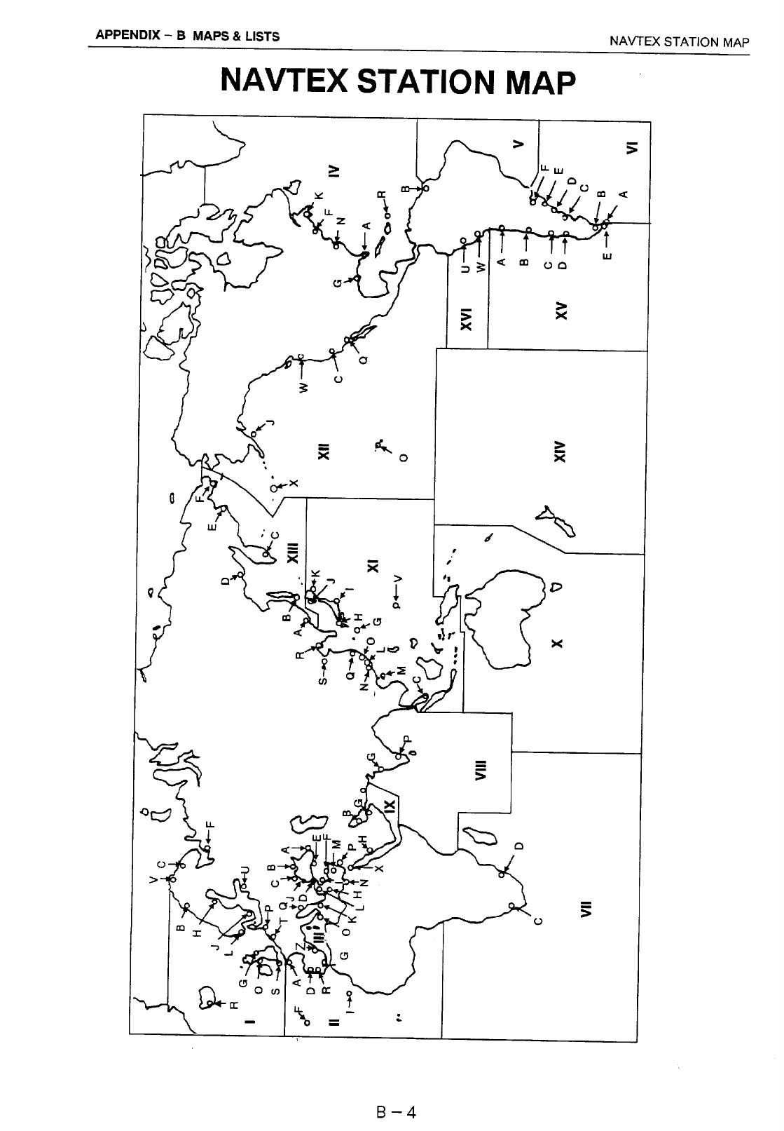
NAVTEX Station Map ....................................................................................B-4
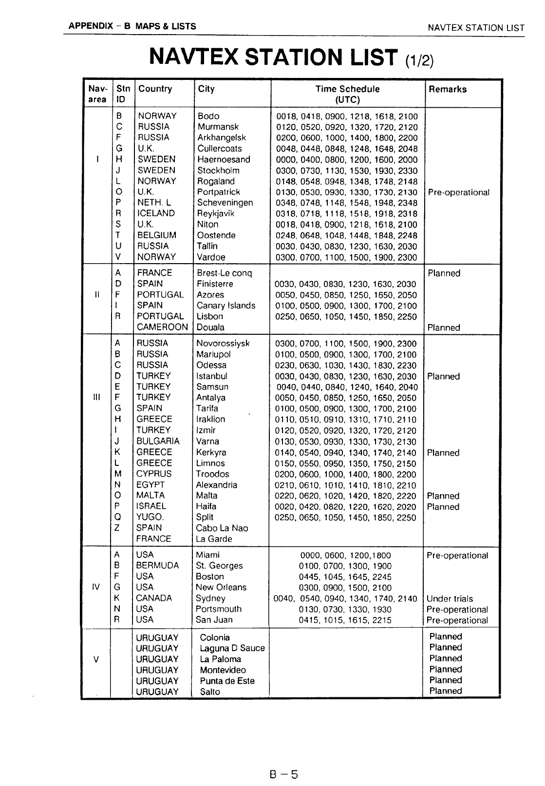
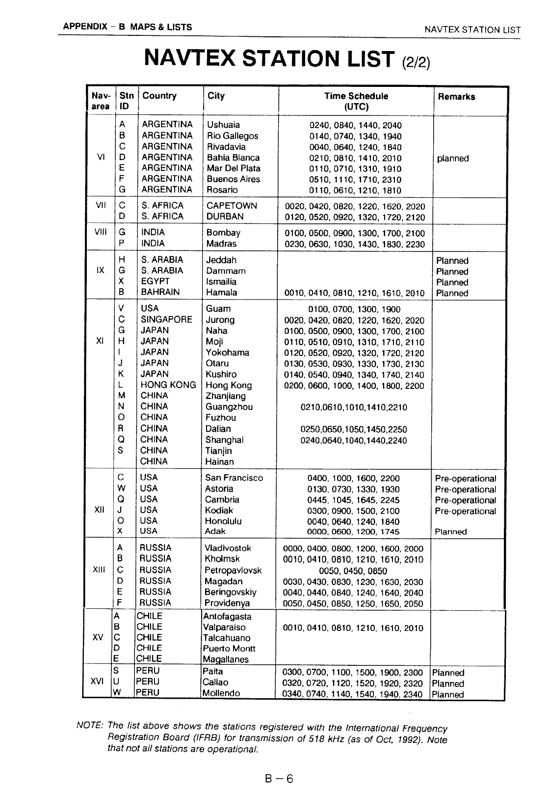
NAVTEX Station List......................................................................................B-5
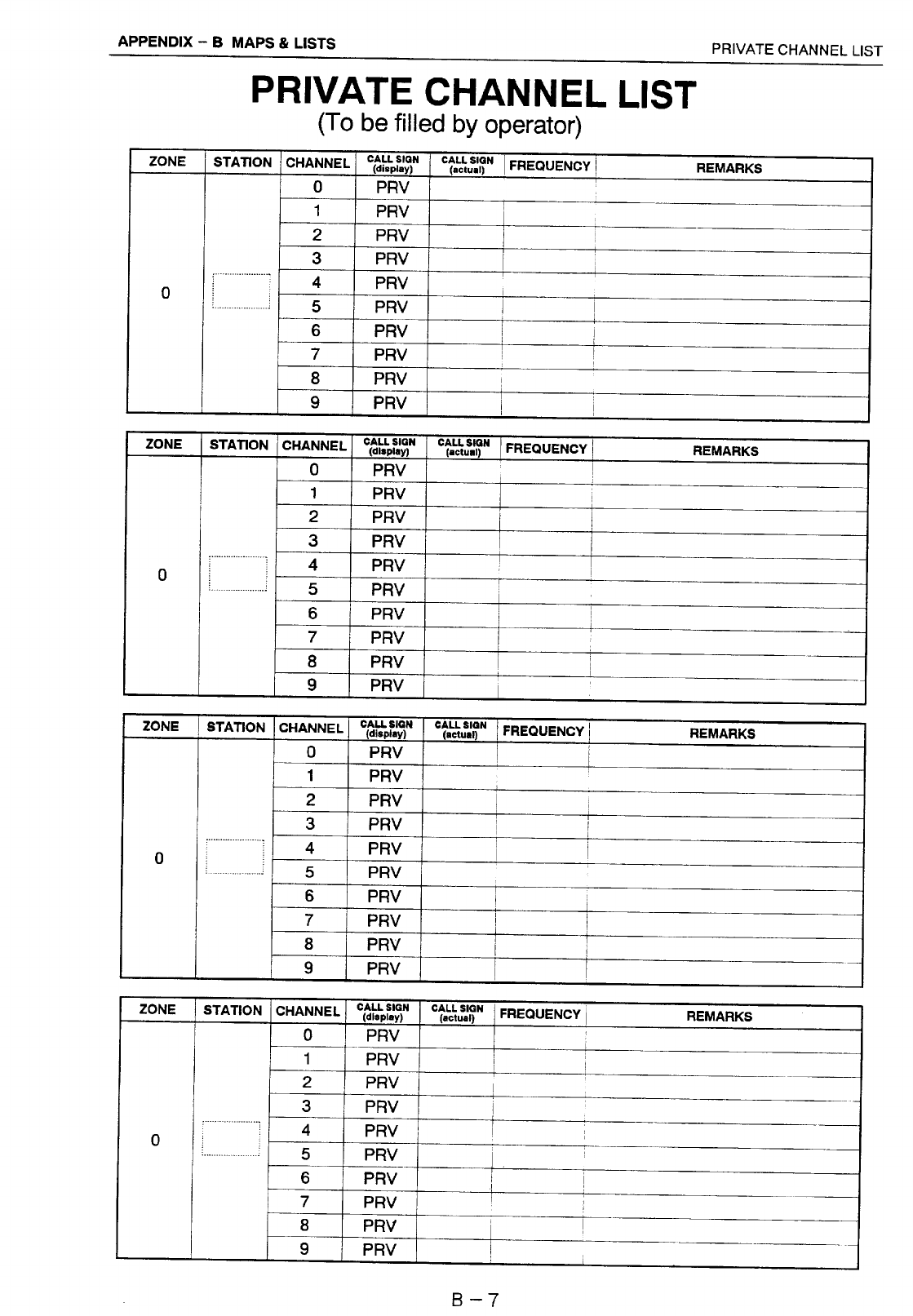
Private Channel List ......................................................................................B-7
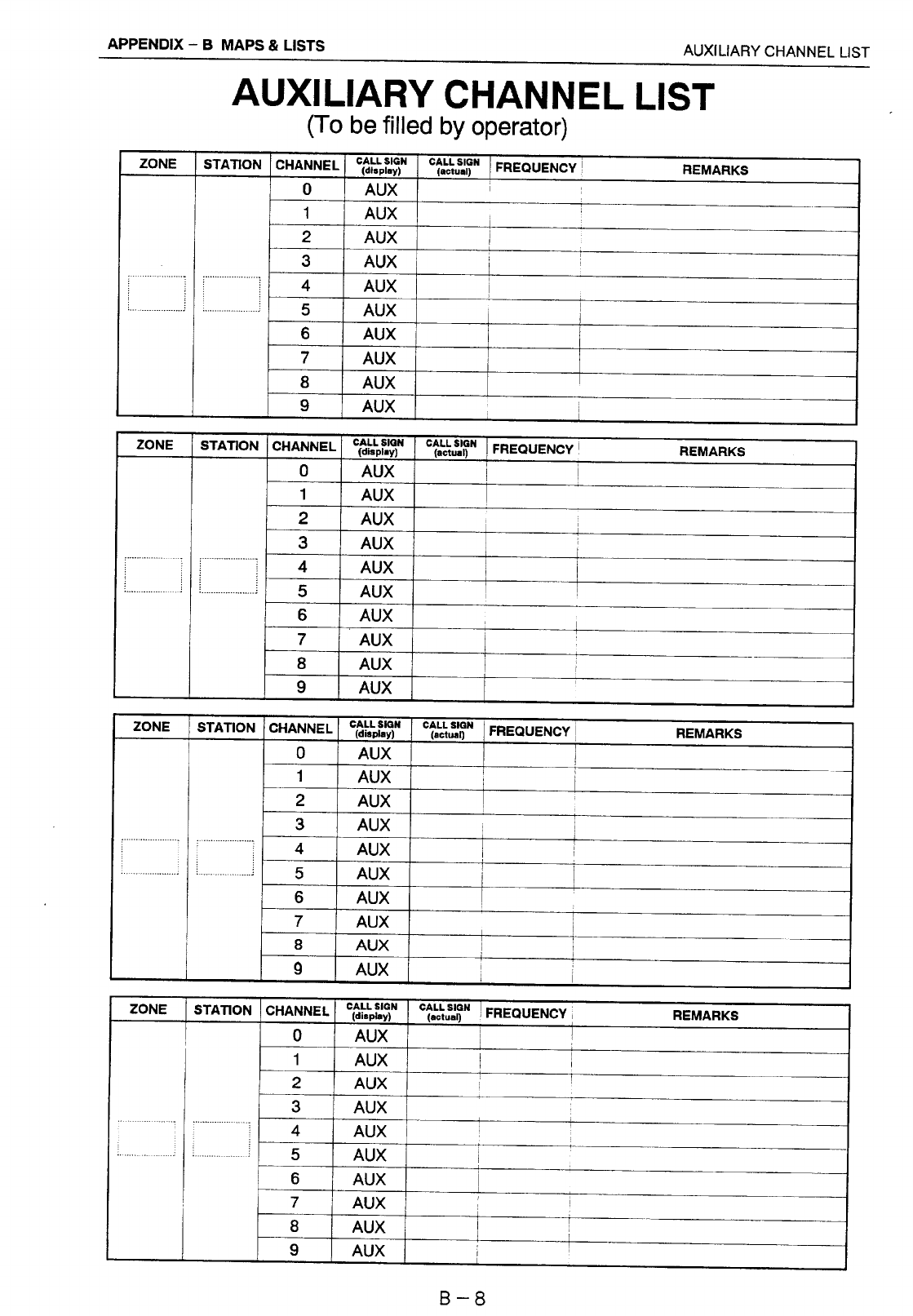
Auxiliary Channel List....................................................................................B-8
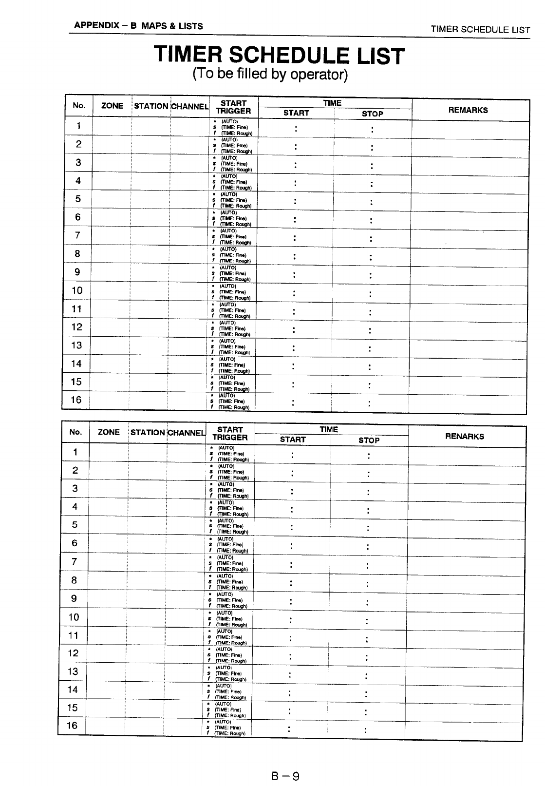
Timer Schedule List.......................................................................................B-9
APPENDIX C IMPROVEMENT OF RECEIVER S/N RATIO
(Remedy for RFI) ...............C-1 to C-2
LISTS ..................................................................................................... L-1 to L-5
OUTLINE DRAWING.................................................................................... D-1
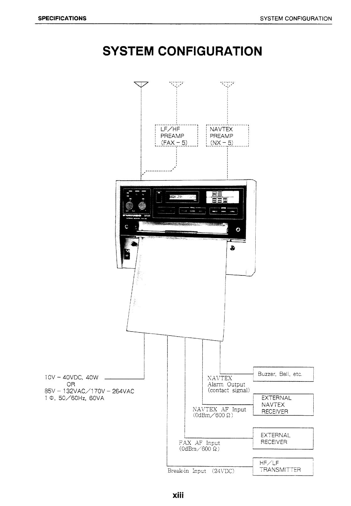
INTERCONNECTION DIAGRAM..................................................................S-1
Declaration of Conformity

SPECIFICATIONS COMPLETE SET
xii
COMPLETE SET
No NAME TYPE MASS Q’TY REMARKS
1 Main Unit FAX-210 12 1
2 Accessories FP08-00600 1 set
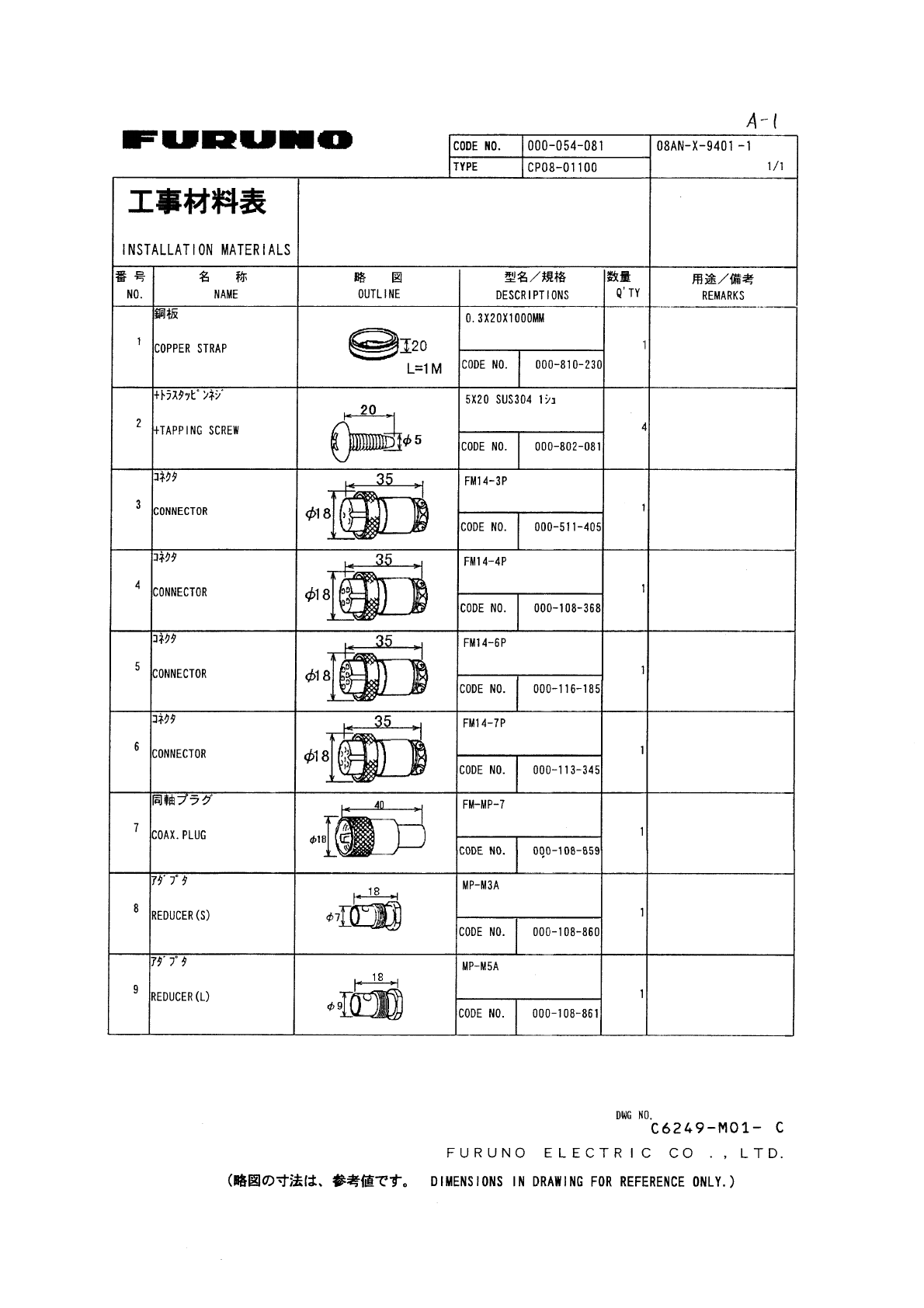
CP08-01100 For ac mains
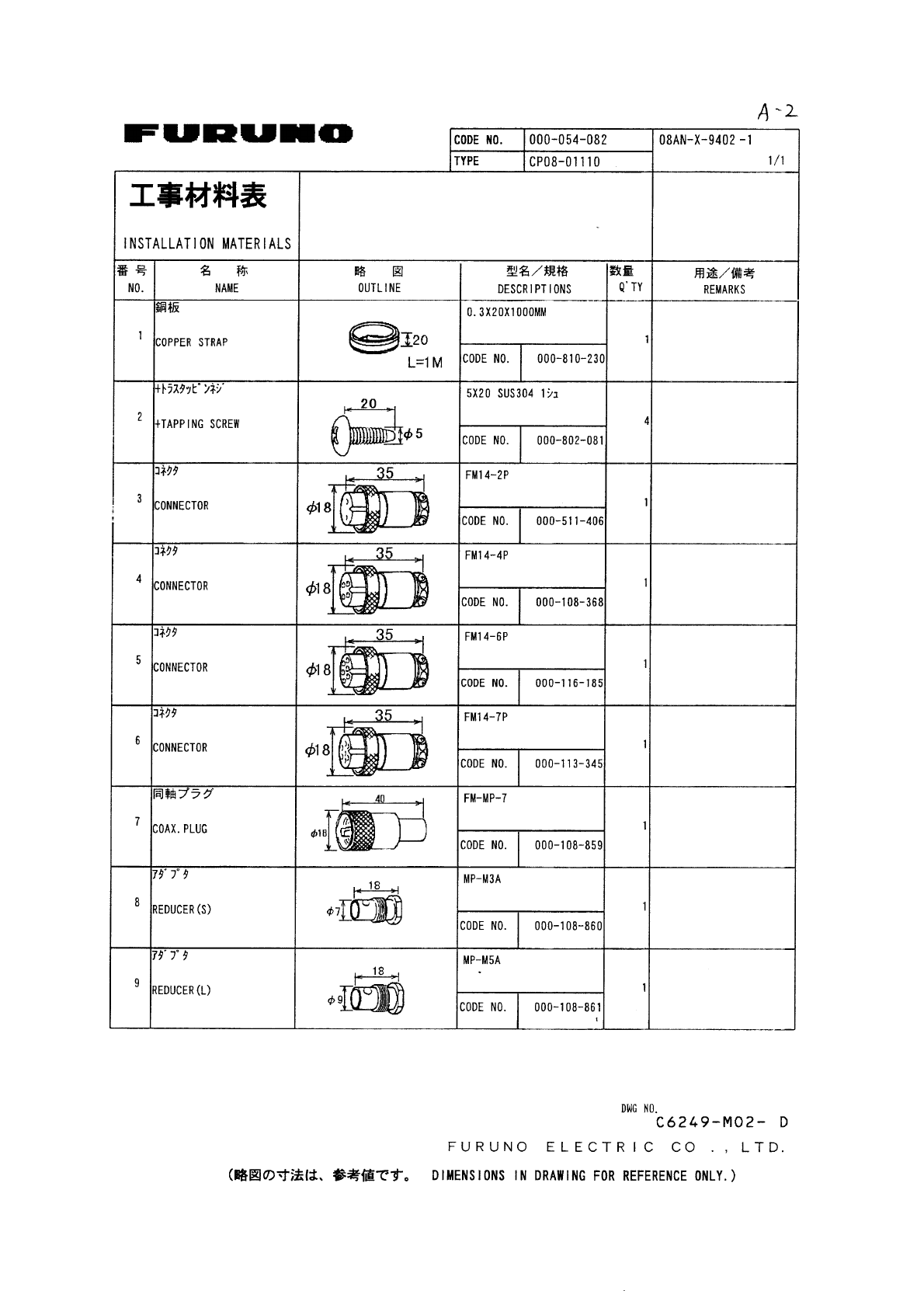
3 Installation Materials CP08-01110 1 set
For dc mains
Either one is
supplied.
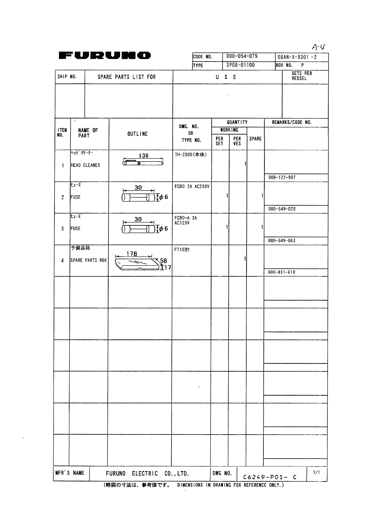
SP08-01100 For ac mains
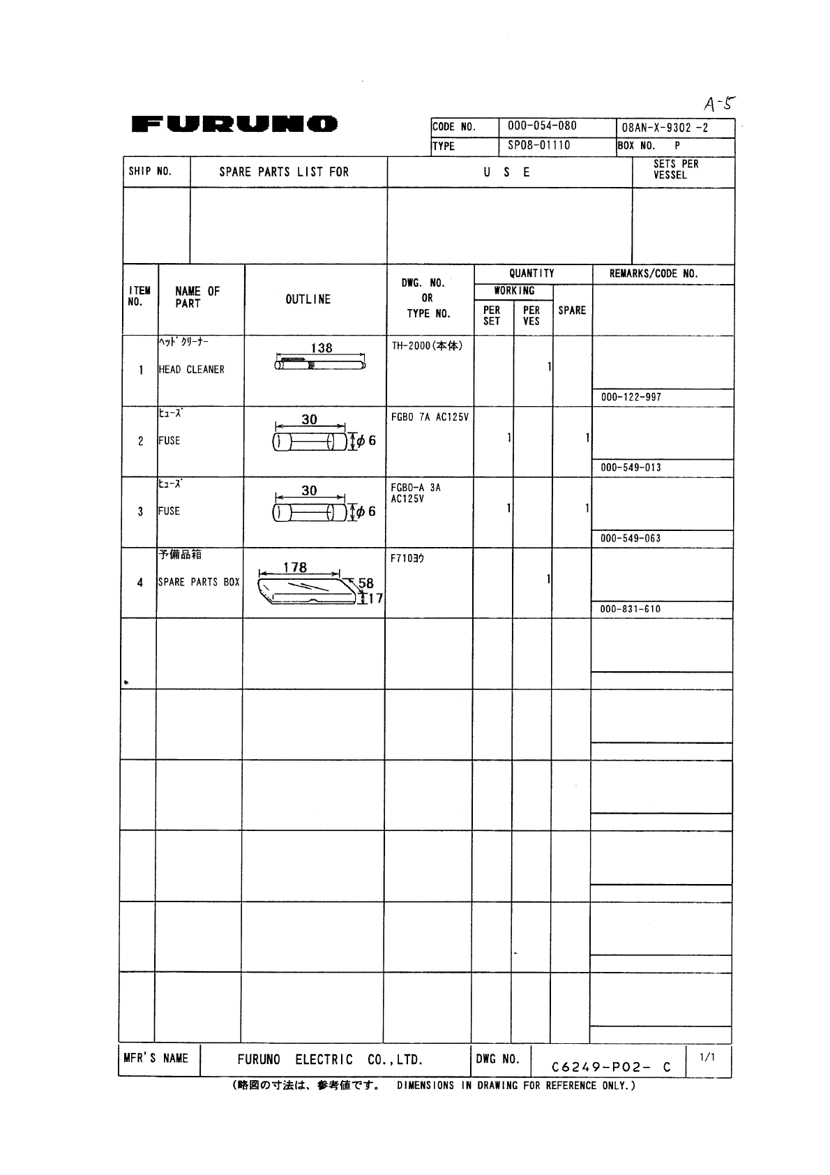
4 Spare Parts SP08-01110 1 set
For dc mains
Either one is
supplied.
With 15 m cable (option)
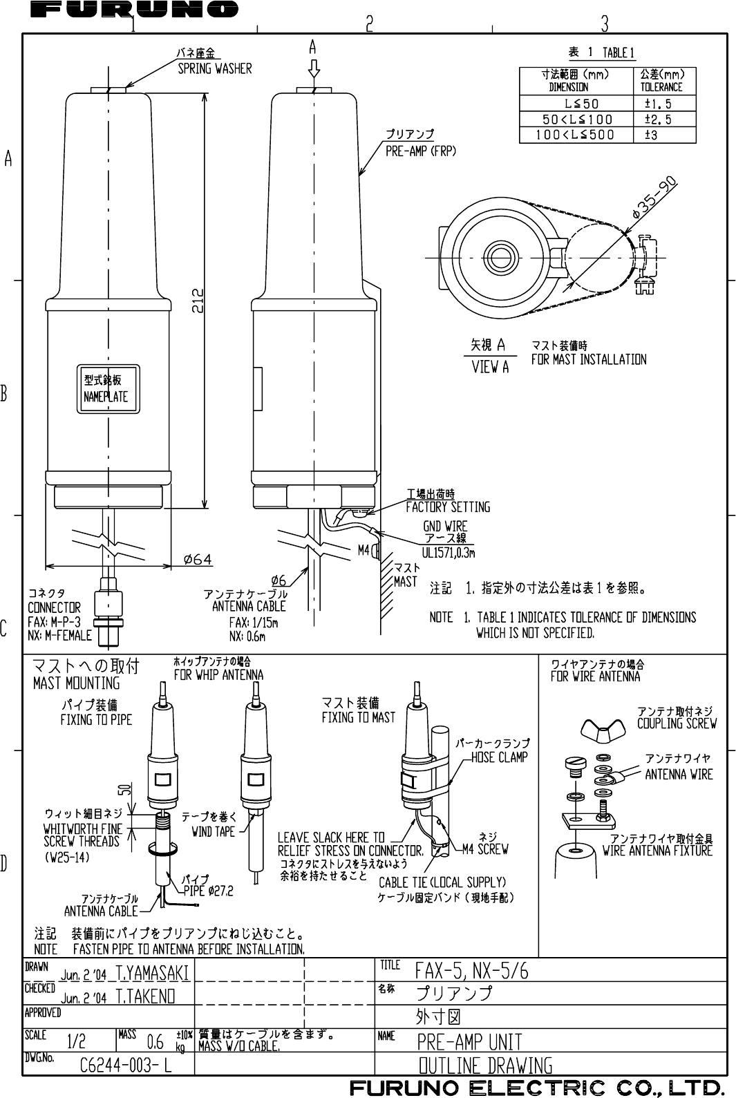
5 LF/HF Preamp Unit FAX-5 0.6 (1) With 1 m cable (option)
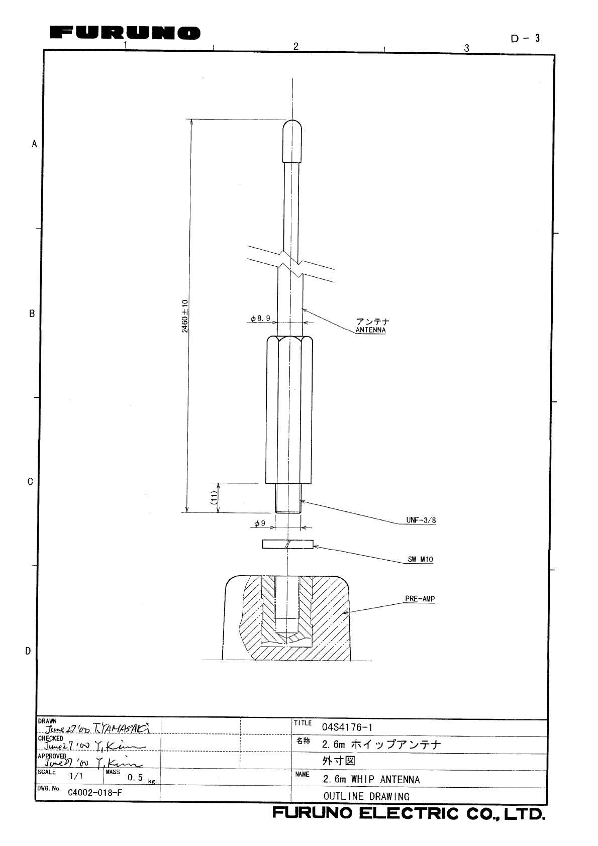
6 Whip Antenna 04S4176-0 0.5 (1) 2.6 m (option)
7 Extension Cable Kit OP04-2 (1) 10m,20m,30m,40m or 50m (option)
8 NAVTEX Board 08P3119 (1) (option)
9 NAVTEX Preamp Unit NX-5 0.6 (1) With 15 m cable (option)
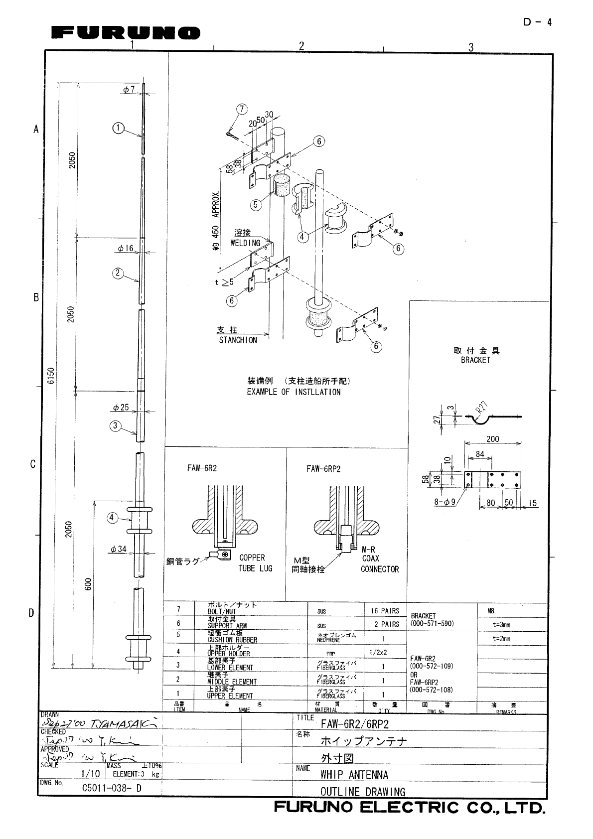
10 Whip Antenna FAW-6R2 3 1 6 m (option)
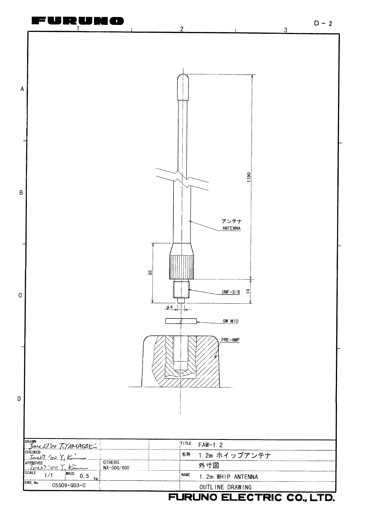
11 Whip Antenna FAW-1.2 1 1.2 m (option)
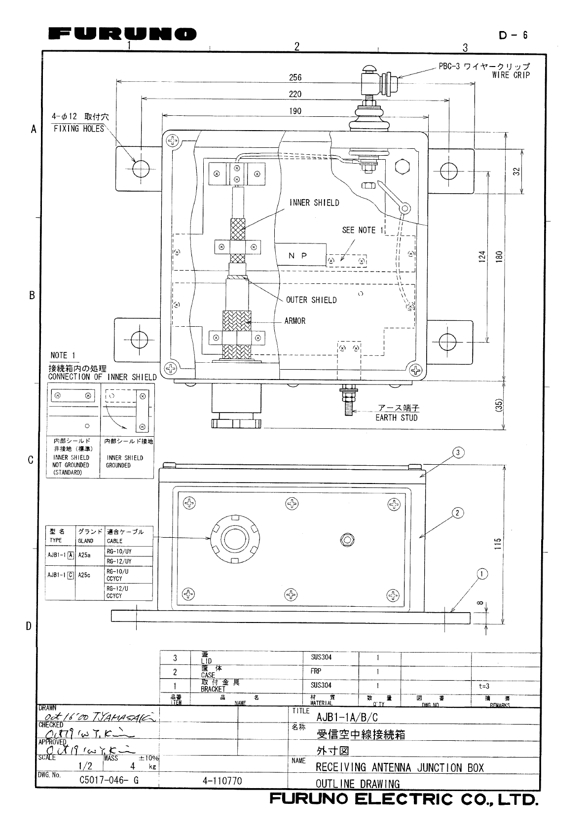
12 Receiving Antenna
Junction Box AJB1-1A 4 1 (option)
13 Clamp OP08-11 1 (option)
INSTALLATION ANTENNA INSTALLATION
4 - 6
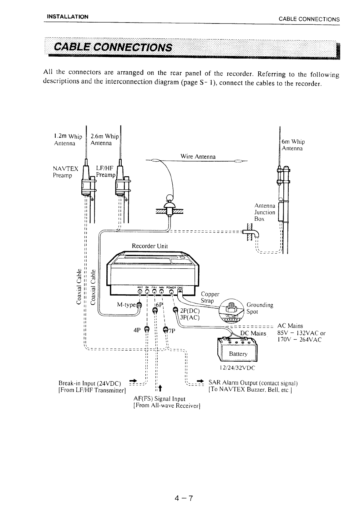
PASSIVE ANTENNA (Wire Antenna)
If the vessel is large enough, install a long-wire or whip antenna of 6 meters or longer. If the
NAVTEX receiver board (option) is not incorporated, it is possible to share the antenna with an
all wave receiver by using an Antenna Multicoupler. Do not share the antenna with the
transmitter.
ACTIVE ANTENNA (Preamp Unit; option)
If your vessel is small and you can not provide space for such a long antenna, it is recommended
to install the preamp unit FAX-5 (or NX-5) and whip antenna of 2.6 meter (or 1.2 meter), respectively.
For 1.2 meter whip antenna, the taping is necessary (see page 4-17).
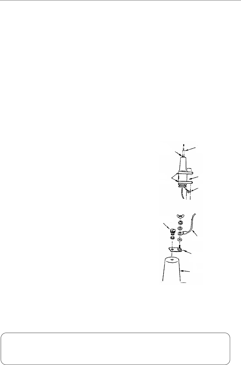
1. Clamp the Preamp Unit tightly on a stub
mast with to stainless steel hose clamps.
(Hose clamps must be arranged locally.)
2. Screw the whip antenna tightly onto the
Preamp Unit.
3. Secure the earth lead of the Preamp Unit to
the nearest grounding spot.
4. Waterproof the antenna junction and other
exposed metallic parts with sealing compound
(silicone rubber, putty, etc).
Instead of using the whip antenna, an antenna wire
of 2 to 3 meter long may be connected as shown
right.
NOTE
Whip
Antenna
Spring
Washer
Hose
Clamp Mast
Grouding Spot
Antenna Wire
Coupling
Nut
Wire Antenna
Fixture
Preamp Unit
I
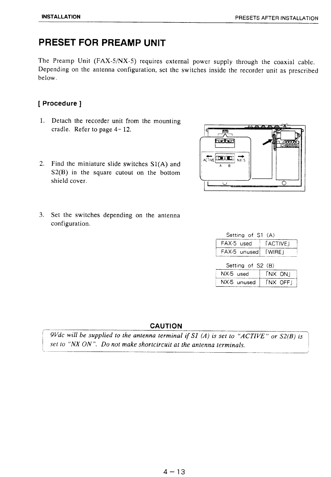
f the Preamp Unit is installed, change the settings of switches (S1/S2) inside th
e
recorder unit to supply 9Vdc to the Preamp Unit. Refer to page 4-13.
I
f receiver sensitivity is insufficient on preamp unit-equipped sets, ground the preamp
unit referring to page C-1.
INSTALLATION TAPING WHIP ANTENNA
4 - 17
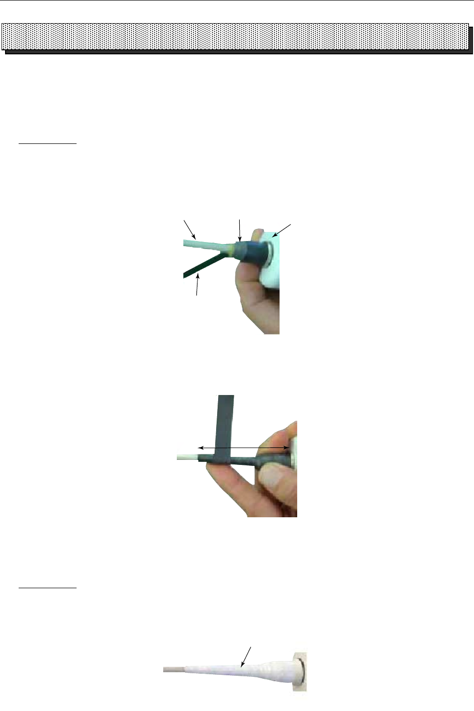
TAPNING WHIP ANTENNA
After inserting the whip antenna to the antenna base, tape the antenna base and whip antenna with
self-vulcanizing tape and vinyl tape to reinforce the whip antenna.
1. Wrap the antenna junction point with butyl 15 tape or the equivalent.
How to wrap
1) Pull the tape to be about two times in length and wind it up, overlapping by 1/2 the width of the
tape.
2) Wrap from bottom to top, i.e., from right to left as in the picture below.
Butyl tape
Whip antenna Base Antenna
3) Wrap the tape from the base to a point about 60 mm, and then back to the base.
Keep tension on edge of tape, using finger to hold tape. Then, squeeze edges of tape with thumb
and index finger.
Wrap approx.
60 mm
2. Completely cover the butyl rubber tape with white vinyl tape, wrapping from the base to the last
wind of butyl tape and then back to the base.
How to wrap
1) Being careful not to pull the tape too tightly, wind tape, overlaping by approx. 1/3 of tape width.
2) Squeeze edges of tape with thumb and index finger.
White vinyl tape
TAPING WHIP ANTENNA
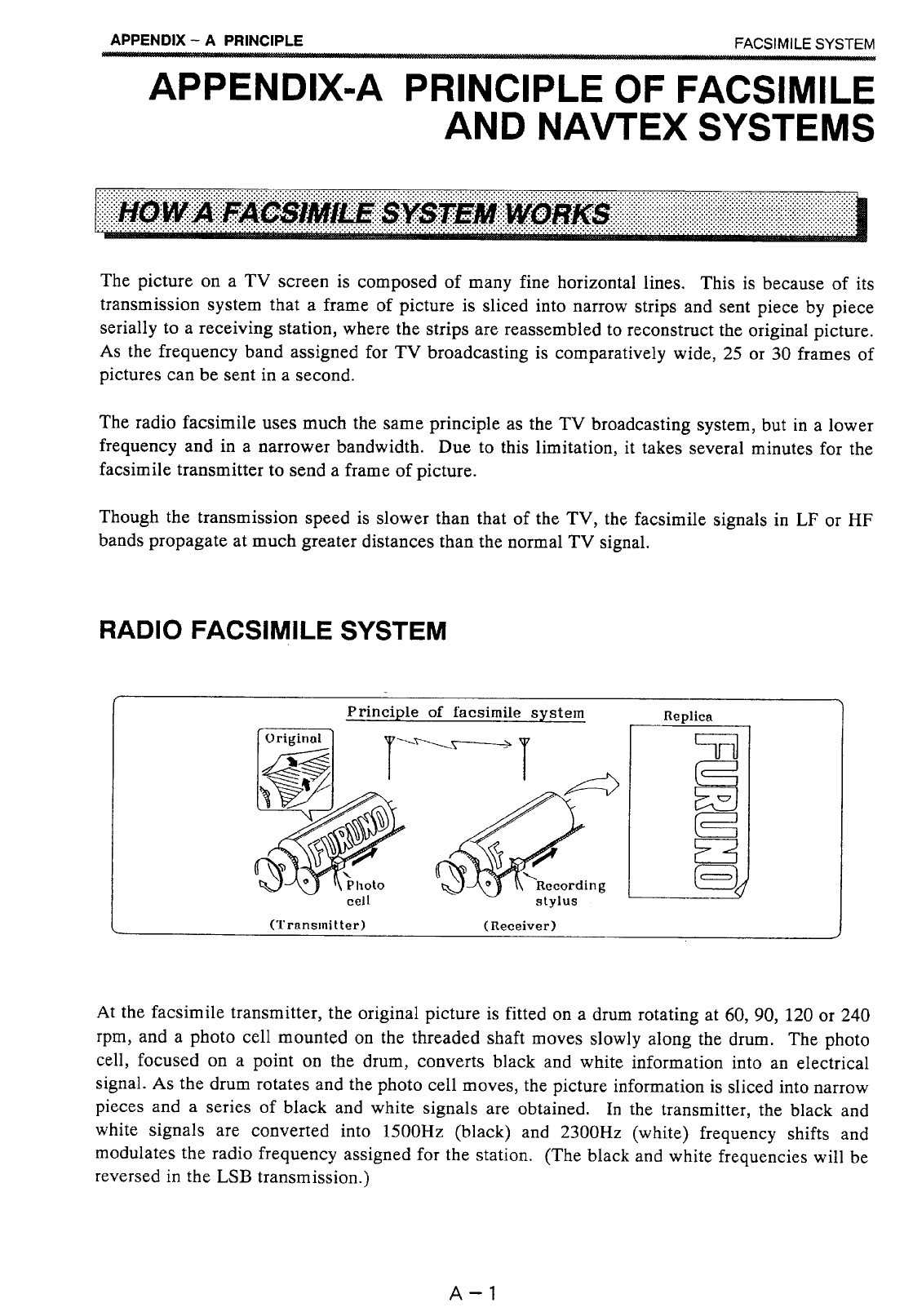


CODENO.
CODENO.CODENO.
CODENO. 000‑054‑083
TYPE
TYPETYPE
TYPE FP08‑00600
略 図
OUTLINE
名 称
NAME
数量
Q'TY 用途/備考
REMARKS
番号
NO.
型名/規格
DESCRIPTIONS
1/1
‑2
ACCESSORIES
付属品表
付属品表付属品表
付属品表
08AN‑X‑9501
サ‑マル紙
THERMALPAPER
TP‑1030A
2
000‑802‑891
1
CODENO.
潤滑油
LUBRICATIONOIL
ミシン油MACHINE28MLイリ
1
000‑149‑213
2
CODENO.
(略図の寸法は、参考値です。 DIMENSIONSINDRAWINGFORREFERENCEONLY.)
(略図の寸法は、参考値です。 DIMENSIONSINDRAWINGFORREFERENCEONLY.)(略図の寸法は、参考値です。 DIMENSIONSINDRAWINGFORREFERENCEONLY.)
(略図の寸法は、参考値です。 DIMENSIONSINDRAWINGFORREFERENCEONLY.)
FURUNO ELECTRIC CO .,LTD.
08AN‑X‑9501
A-3
D-1
Jun.14'04
H.Hayashi
D-5
23
D
C
B
A
1
NOTE
*2. OPTION.
注記
*1)造船所手配。
*2)オプション。
*1. SHIPYARD SUPPLY.
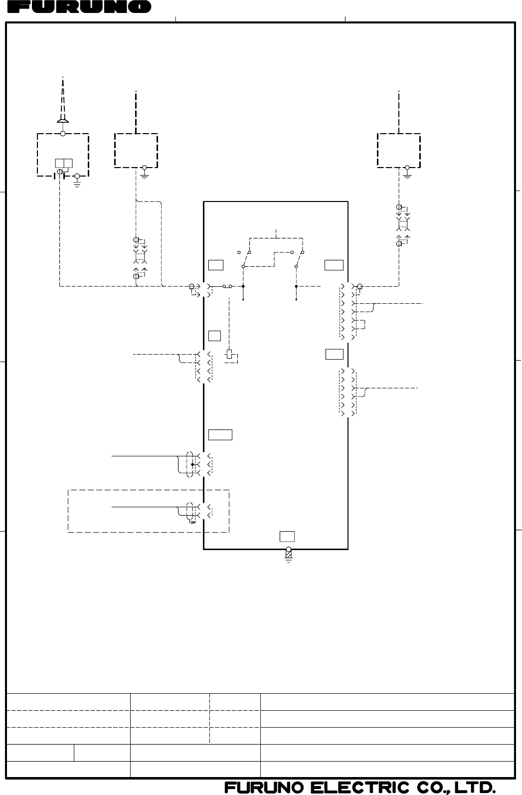
FAX‑210
J2
RF
NX
RF
FAX
ANT
MAIN UNIT
M‑P‑7 J4
NAV
NX‑5
0V
1
2
ALARM
ALARM
NAV OUT
NAV IN
0V
4
3
6
7
5
DPYC‑1.5 *1
(1A,20Wmax)
BUZZER OR BELL
OFF
NX ON
NX
S2
POWER
AC
1
2
3
BK
FM14‑7P
本体
AC
GND
FM14‑3P J1
PREAMP
プリアンプ
WHIP ANTENNA
NX‑5 *2
1
2
(+)
(‑)
FM14‑2P J1
100/110/200/220VAC
1φ,50/60Hz
10‑40VDC
*1
DPYC‑2.5
*1
DPYC‑1.5
DC電源のとき FOR DC SOURCE
GND
0.3x20x1000
COPPER STRAP
アース銅板
FAX‑5 *2
PREAMP
プリアンプ
WHIP ANTENNA
M‑A‑JJ
*1
3D‑2V,1m
3D‑2V,15m
*1
送信機BK端子へ
(24VDC)
TRANSMITTER BK
DPYC‑1.5
2
3
1
4NC
NC
BK
BK
J3
BK
FM14‑4P
(0dBm,600Ω)
FAX EXT.RECEVIER
FAX用外部受信機
J5
FAX
NC
NC
0V
FAX IN
0V
FAX OUT
6
5
3
4
1
2DPYCS‑1.5
*1
FM14‑6P
3D‑2V,0.6m
RG‑10/UY *1
ACTWIRE
S1
12V M‑A‑JJ
*1
RG‑10/UY
*1
ブザー/ベル
ホイップアンテナ
WHIP ANTENNA
接続箱 *2
JUNCTION BOX
HC
2.6m
ホイップアンテナ 1.2m
ホイップアンテナ
*2*2
*2
UL1571
0.3m UL1571
0.3m
kg
名称
ファクシミリ受画装置
相互結線図
FACSIMILE RECEIVER
INTERCONNECTION DIAGRAM
FAX‑210
T.YAMASAKI
Aug. 3 '04
DRAWN
CHECKED
APPROVED
SCALE
DWG.No.
MASS NAME
TITLE
Aug. 3 '04
T.MATSUGUCHI
C6249‑C01‑ D
H.Hayashi
Aug.5'04
S-1