Furuno Fcv 292 Users Manual F
FCV-292 to the manual f198117b-5e1d-4811-b540-fd97b544e271
2015-02-02
: Furuno Furuno-Fcv-292-Users-Manual-428709 furuno-fcv-292-users-manual-428709 furuno pdf
Open the PDF directly: View PDF ![]() .
.
Page Count: 69
- SAFETY INSTRUCTIONS
- A Word To Furuno FCV-292 Owners:
- Table of Contents
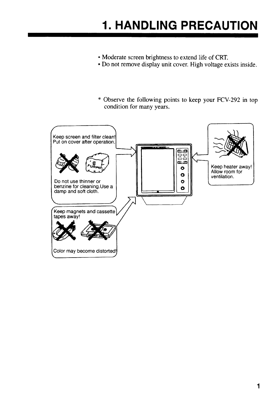
- 1. HANDLING PRECAUTION
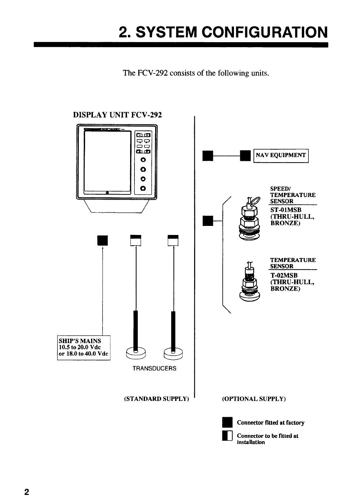
- 2. SYSTEM CONFIGURATION
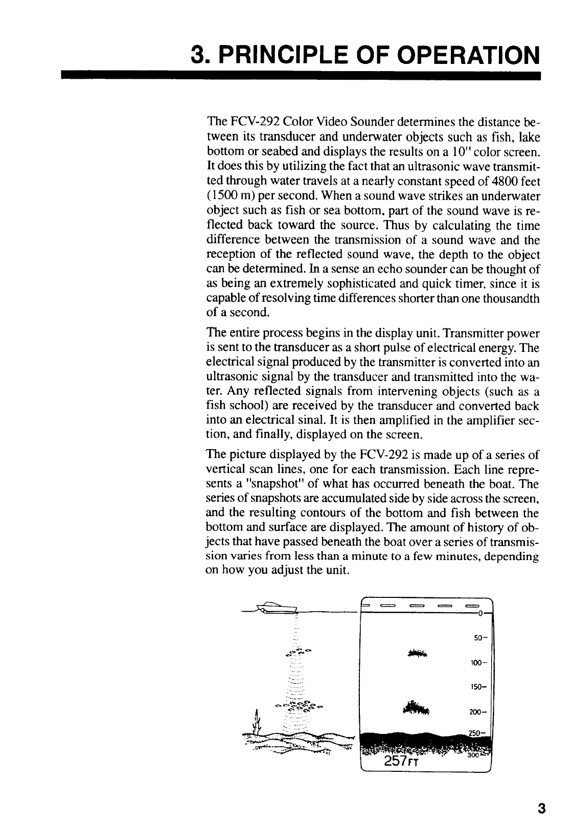
- 3. PRINCIPLE OF OPERATION
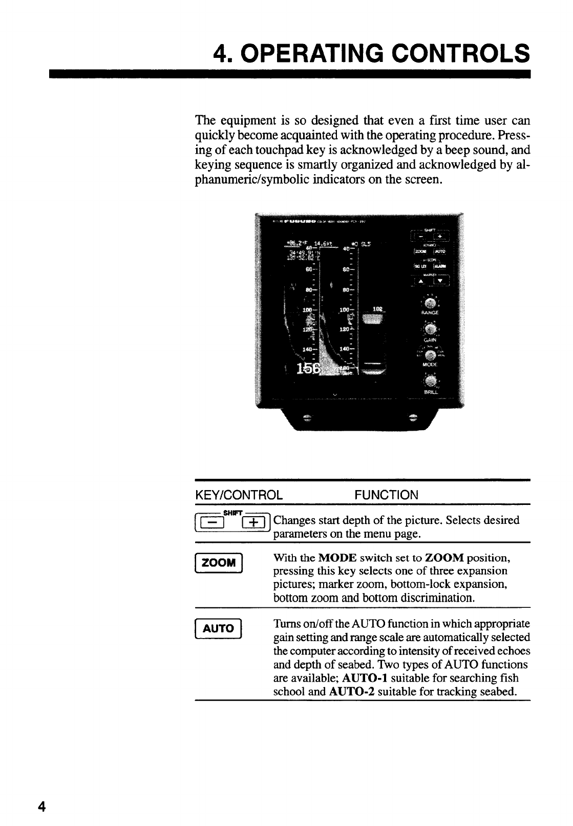
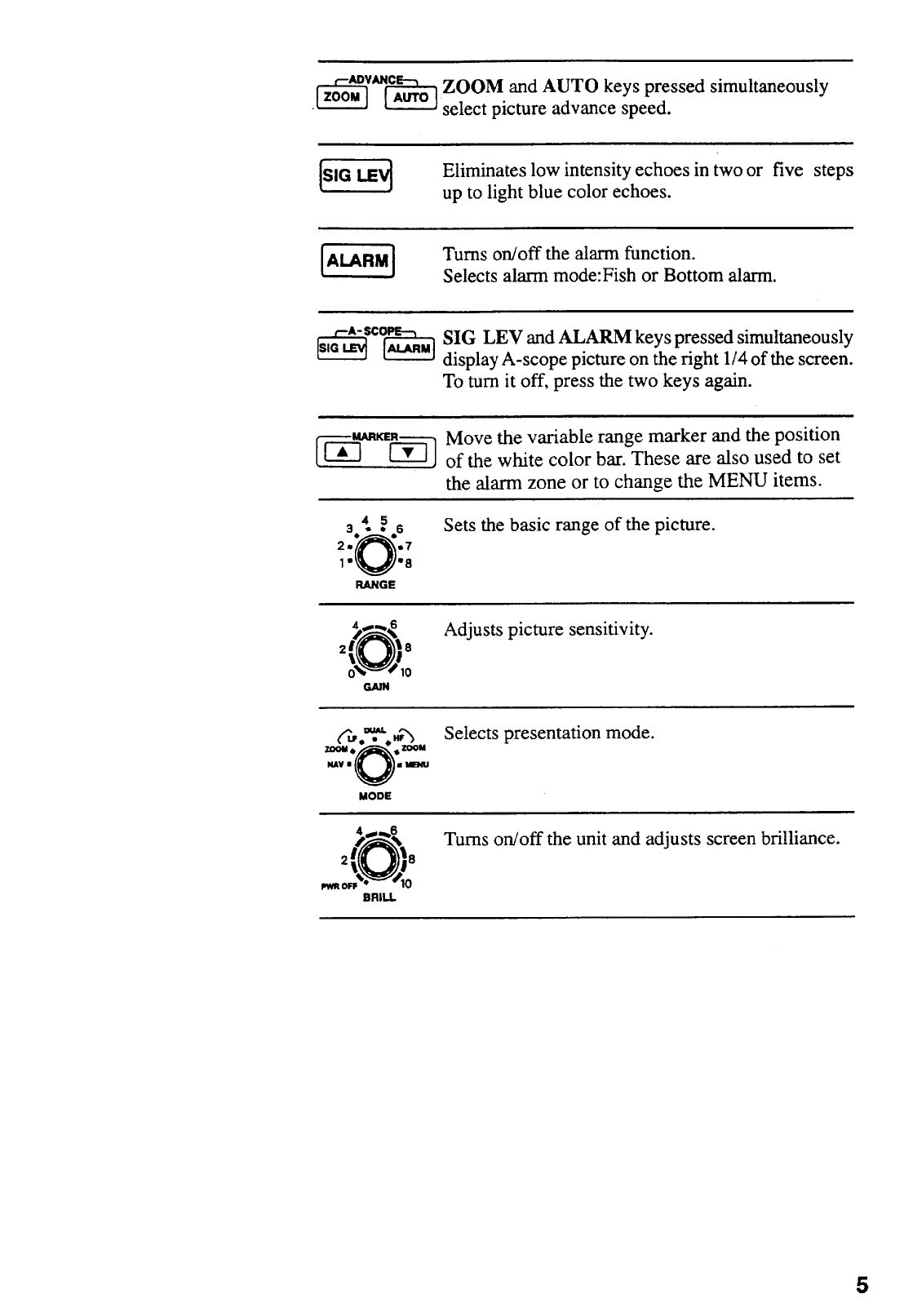
- 4. OPERATING CONTROLS
- 5. BASIC OPERATION
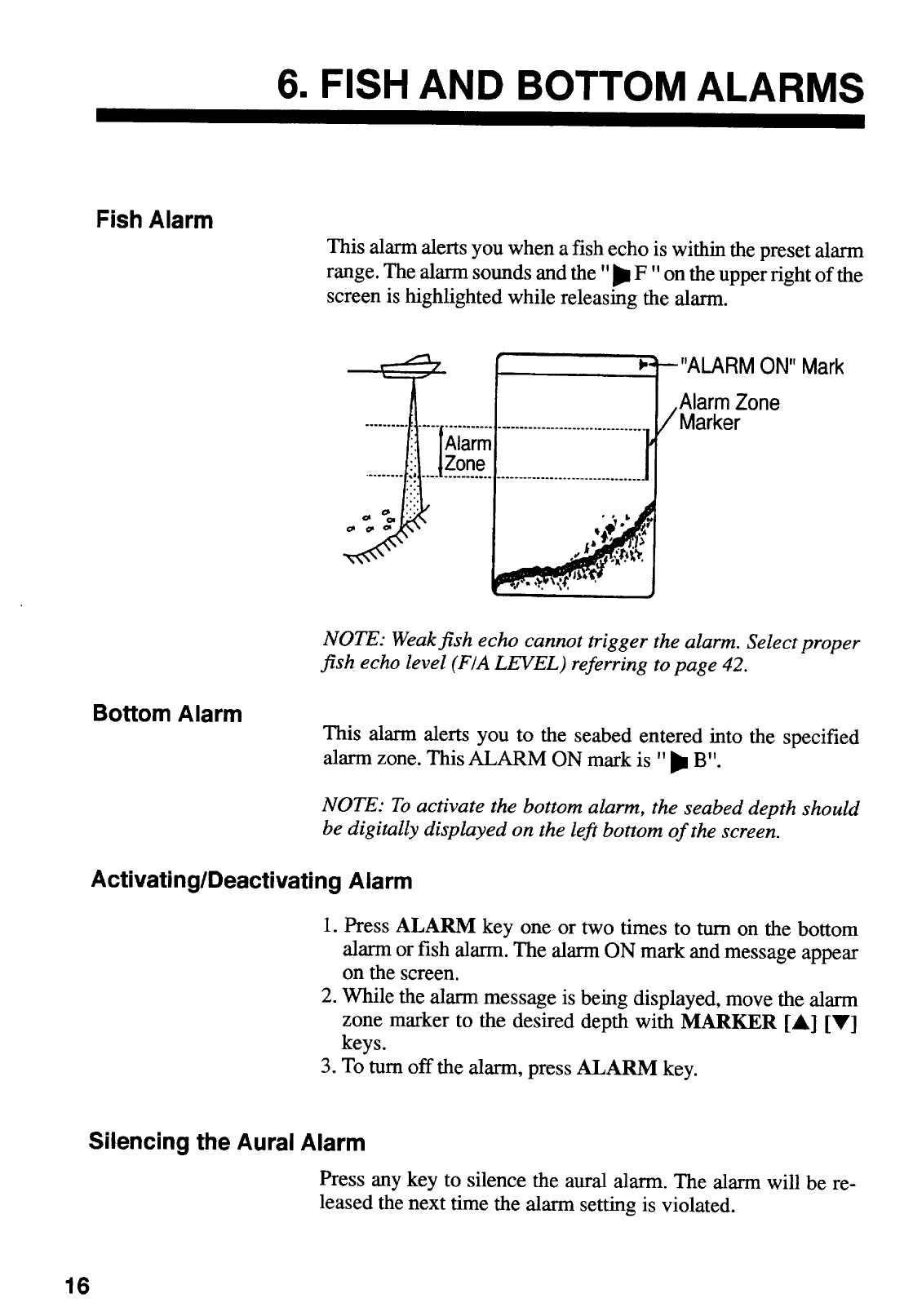
- 6. FISH AND BOTTOM ALARMS
- 7. ADJUSTING PICTURE BY MENU
- 8. DISPLAYS
- 9. INTERPRETING THE DISPLAY
- 10. MAINTENANCE
- 11. TROUBLESHOOTING
- 12. INSTLLATION
- 13. SYSTEM MENU SETTING
- 14. SPECIFICATIONS
- APPENDIX
- OUTLINE DRAWING
- INTERCONNECTION DIAGRAM
Back
Your Local Agent/DealerYour Local Agent/Dealer
9-52 Ashihara-cho,9-52 Ashihara-cho,
Nishinomi
y
a, Ja
p
anNishinomi
y
a, Ja
p
an
Tele
p
hone :Tele
p
hone : 0798-65-21110798-65-2111
fa
x
fa
x
0798-65-42000798-65-4200
::
F
IRST EDITION :
F
IRST EDITION : OCT.OCT. 19941994
Printed in JapanPrinted in Japan
A
ll ri
g
hts reserved.
A
ll ri
g
hts reserved.
L1L1 :: DEC.DEC. 24,200324,2003
PUB.No.PUB.No. OME-23520OME-23520
*00080637800**00080637800*
*00080637800**00080637800*
(( TENITENI )) FCV-292FCV-292 * 0 0 0 8 0 6 3 7 8 0 0 ** 0 0 0 8 0 6 3 7 8 0 0 *
*OME23520L10**OME23520L10*
*OME23520L10**OME23520L10*
* O M E 2 3 5 2 0 L 1 0 ** O M E 2 3 5 2 0 L 1 0 *

ii
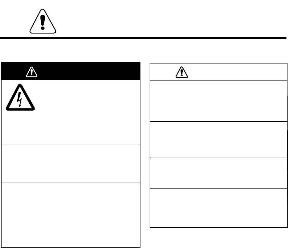
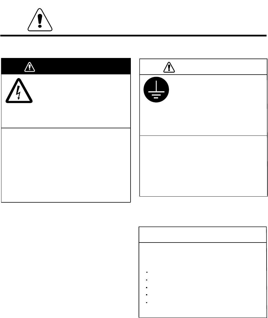
CAUTION
Do not place liquid-filled containers
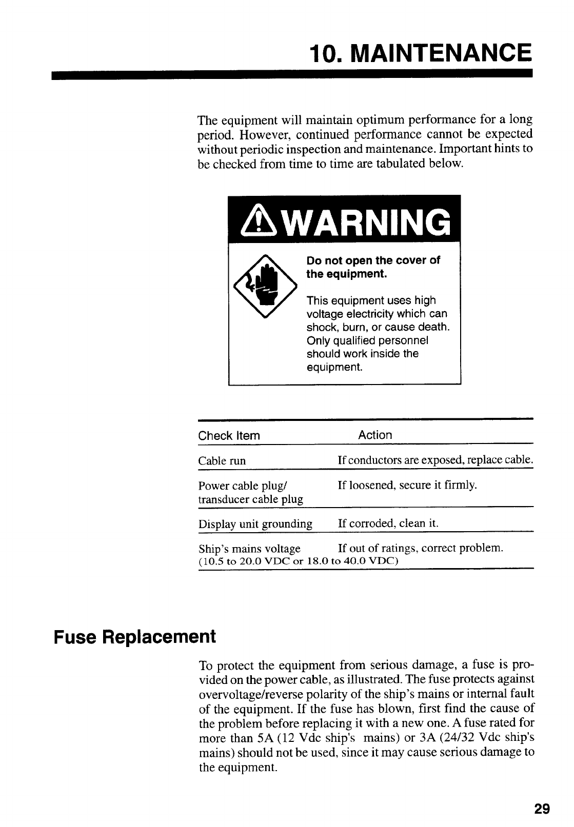
WARNING
Do not dissasemble or modify the
equipment.
Fire, electrical shock or serious injury can result.
Do not open the cover of
the equipment.
This equipment uses high voltage
electricity which can shock, burn,
or cause death.
Only qualified personnel should
work inside the equipment.
Immediately turn off the power at the
ship's mains switchboard if water or
foreign object falls into the equipment
Continued use of the equipment can cause fire,
electrical shock or serious injury.
SAFETY INFORMATION
FOR THE OPERATOR
or the equipment is emitting smoke or
fire.
on the top of the equipment.
Fire or electrical shock can result if a liquid
spills into the equipment.
Do not place heater near the equipment.
Heat can melt the power cord, which can
result in fire or electrical shock.
Do not operate the unit with wet hands.
Electrical shock can result.
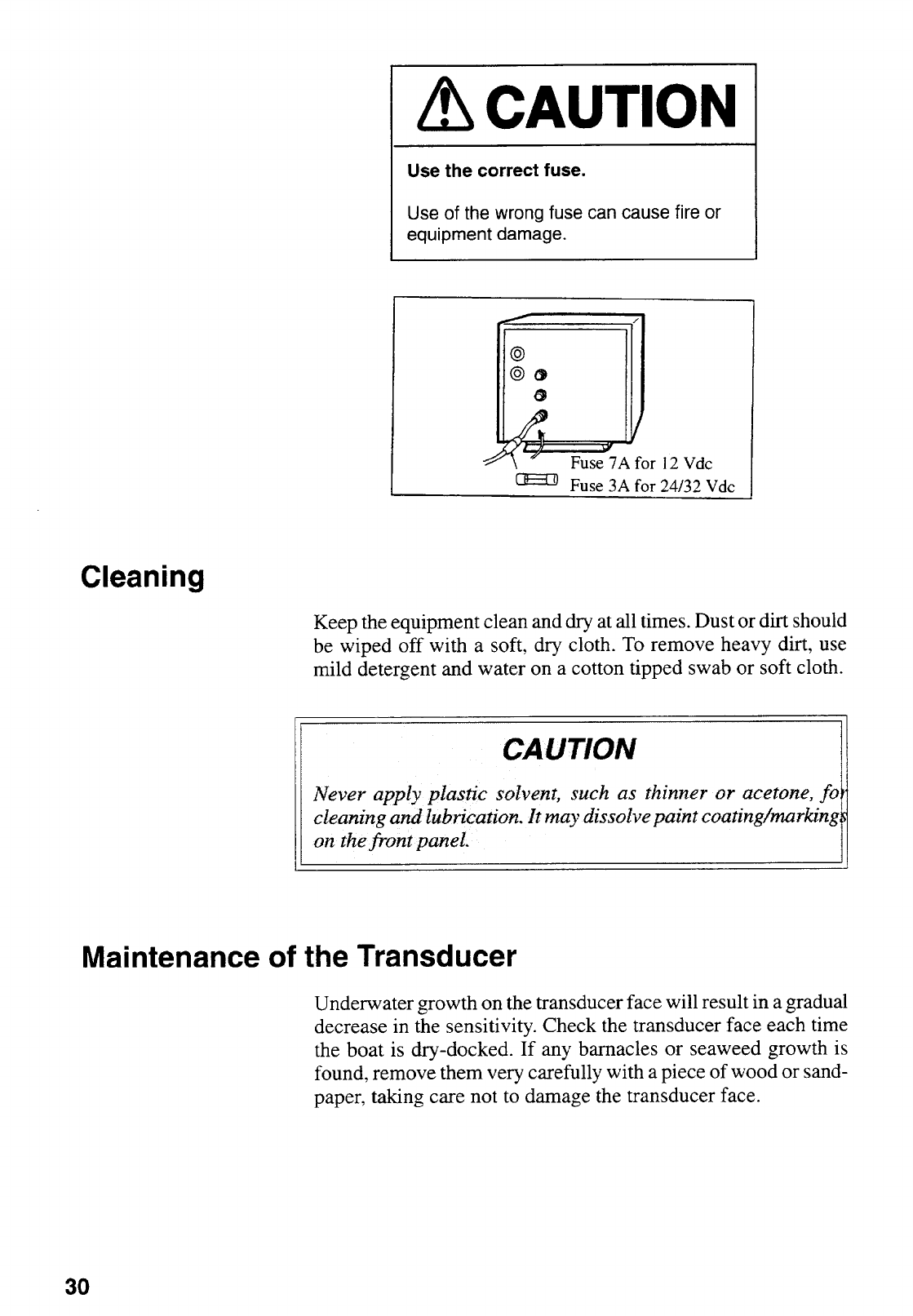
Use the correct fuse.
Use of the wrong fuse can cause fire or
equipment damage.
(Continued on next page)
iv
CAUTION
WARNING
Turn off the power at the ship's mains
switchboard before beginning the
installation. Post a warning sign near
the switchboard to ensure that the
power will not be applied while the
equipment is being installed.
Only qualified personnel
should work inside the
equipment.
This equipment uses high voltage
electricity which can shock, burn,
or cause death.
SAFETY INFORMATION
FOR THE INSTALLER
Ungrounded equipment can give
off or receive electro-magnetic
interference or cause electrical
shock.
Confirm that the power supply voltage
is compatible with the voltage rating
of the equipment.
Connection to the wrong power supply can
cause fire or equipment damage. The voltage
rating appears on the label at the rear of the
equipment.
Serious injury or death can result if the power is
not turned off, or is applied while the equipment
is being installed.
Ground the equipment to
prevent electrical shock and
mutual interference.
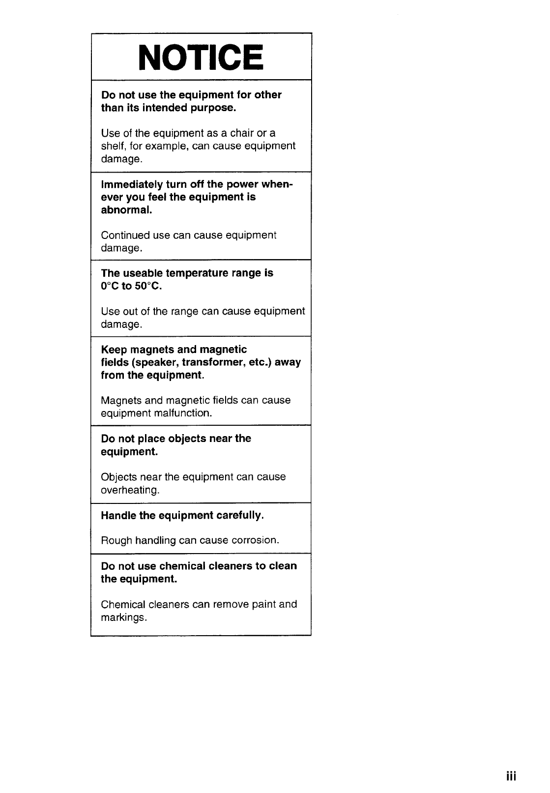
NOTICE
The mounting location must satisfy the
following conditions:
Away from rain and water splash
Out of direct sunlight
Away from air conditioner vents
Away from magnets and magnetic fields
Moderate and stable in temperature and
humidity

vii
Table of Contents
A Word To Furuno FCV-292 Owners:.................................................................. i
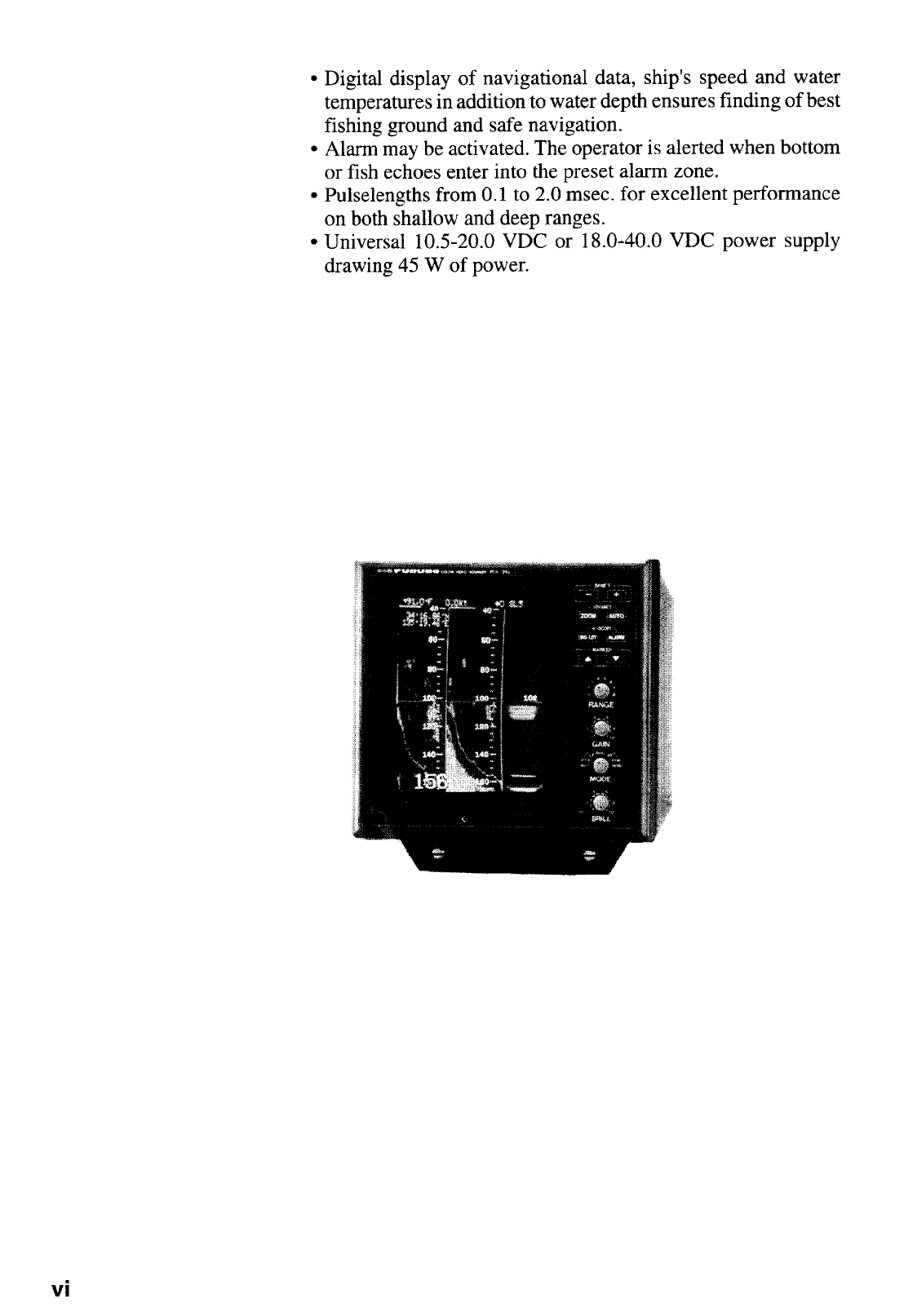
Features ................................................................................................................................ i
1.HANDLING PRECAUTION................................................................................ 1
2.SYSTEM CONFIGURATION.............................................................................. 2
3.PRINCIPLE OF OPERATION ............................................................................ 3
4.OPERATING CONTROLS ................................................................................. 4
5.BASIC OPERATION .......................................................................................... 6
Power ON/OFF and Brilliance Control................................................................................... 6
Demonstration Picture...........................................................................................................6
Presentation Mode Selection ................................................................................................ 6
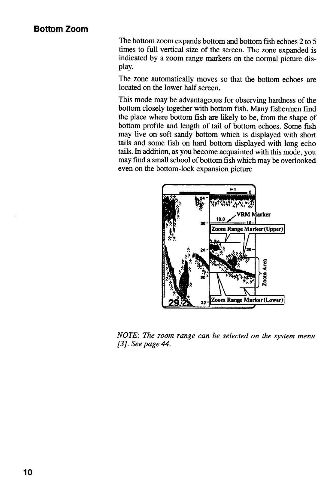
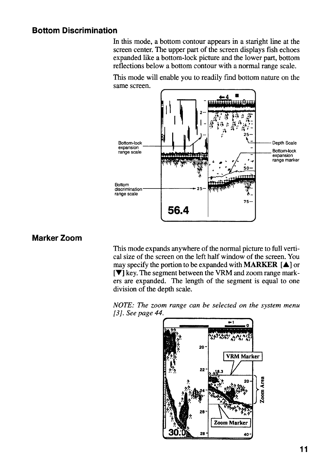
Zoom Picture Selection.........................................................................................................9
Automatic Operation ........................................................................................................... 12
Manual Operation ...............................................................................................................12
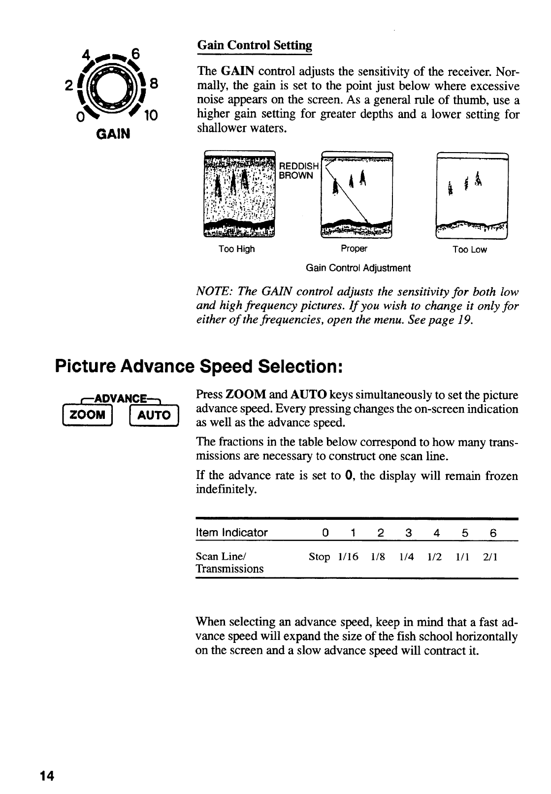
Picture Advance Speed Selection....................................................................................... 14
Eliminating Low Intensity Echoes........................................................................................ 15
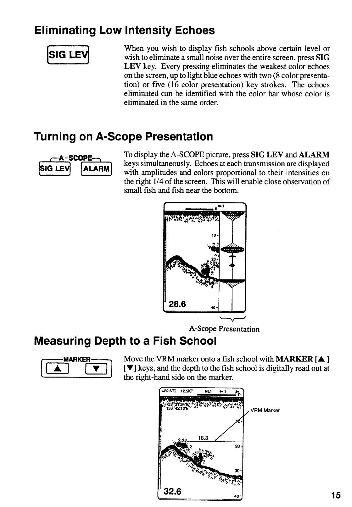
Turning on A-Scope Presentation ....................................................................................... 15
Measuring Depth to Fish School......................................................................................... 15
6.FISH AND BOTTOM ALARMS........................................................................ 16
7.ADJUSTING PICTURE BY MENU .................................................................. 18
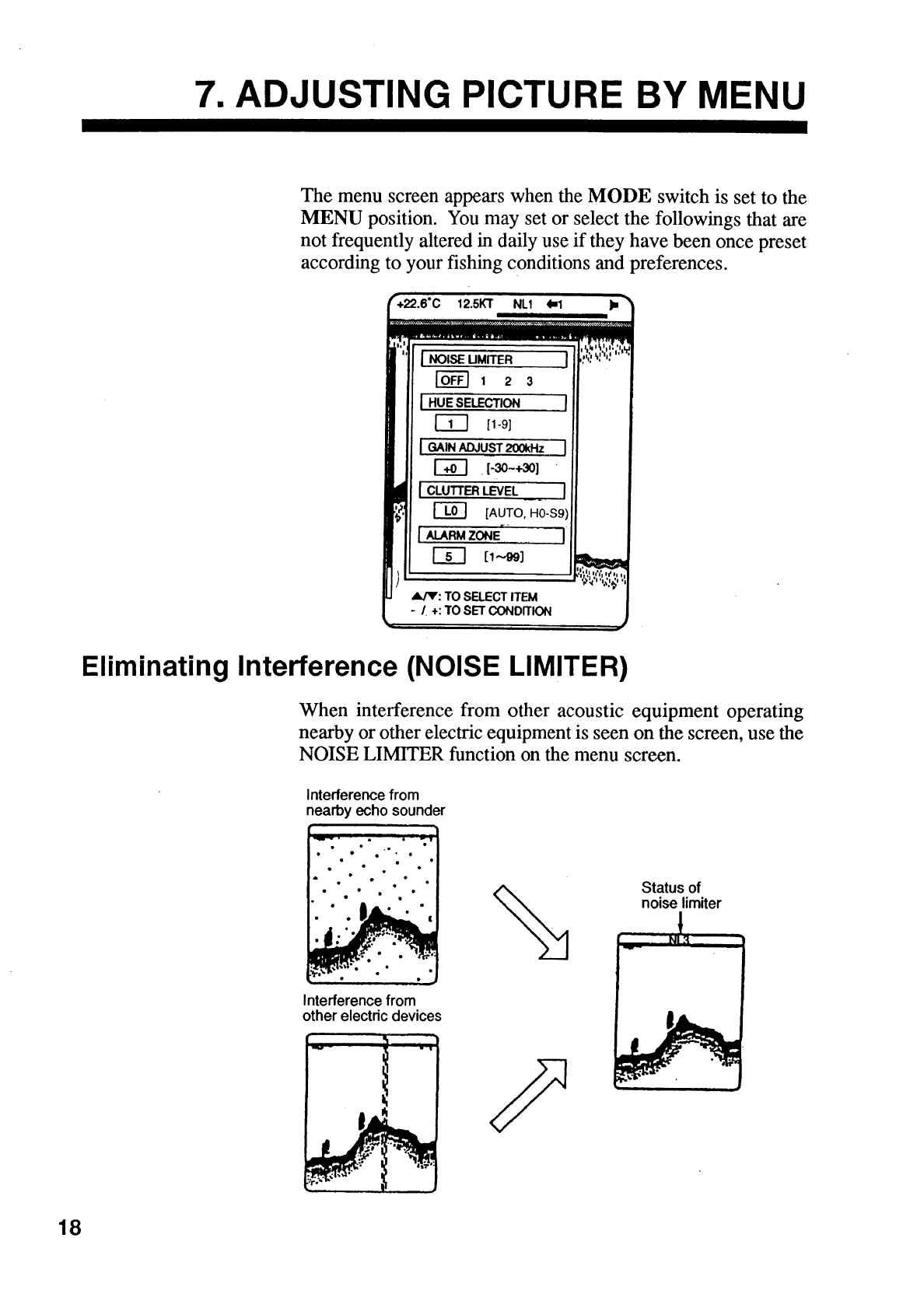
Eliminating Interference (NOISE LIMITER) ......................................................................... 18
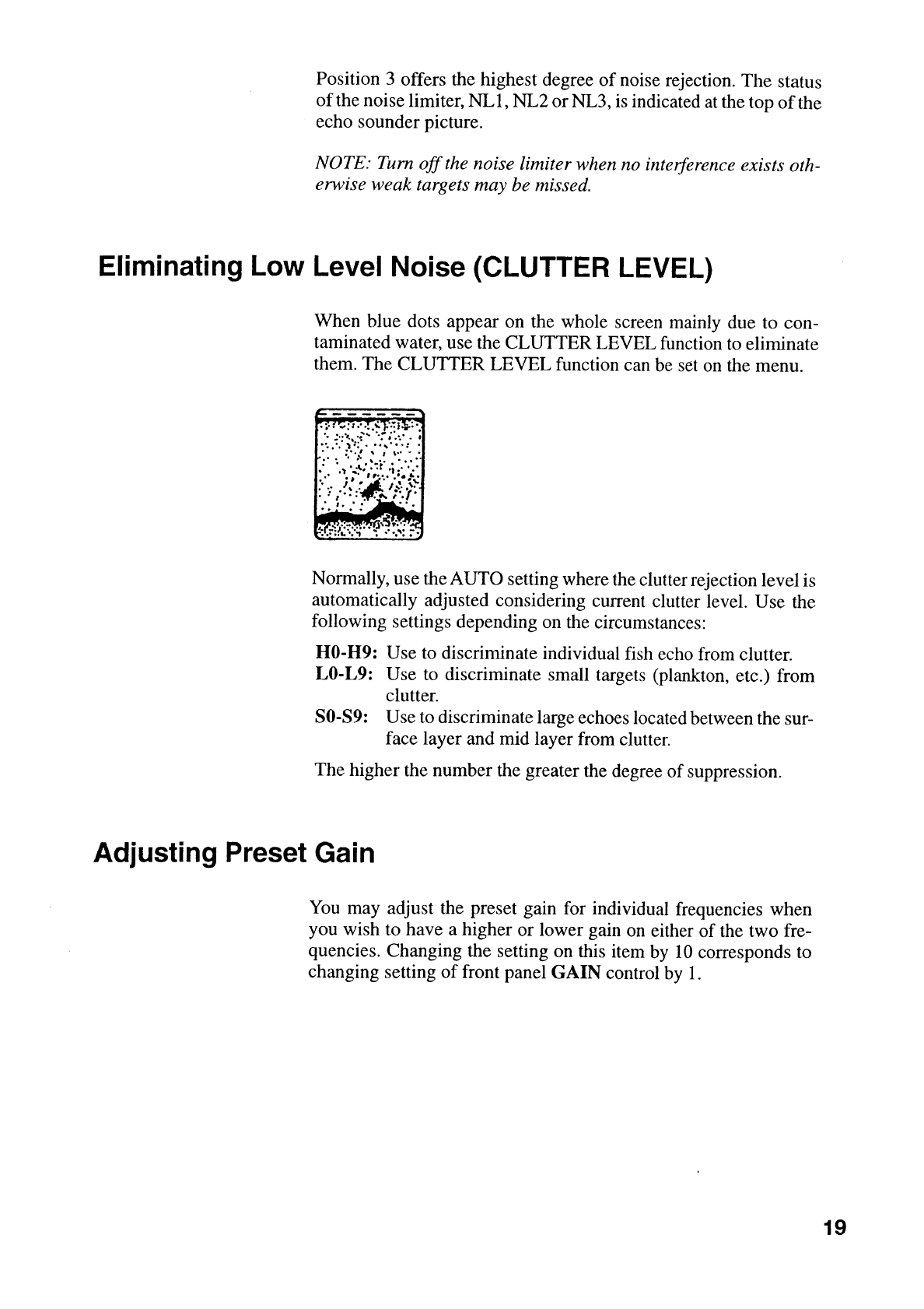
Eliminating Low Level Noise (CLUTTER LEVEL)................................................................ 19
Adjusting Preset Gain ......................................................................................................... 19
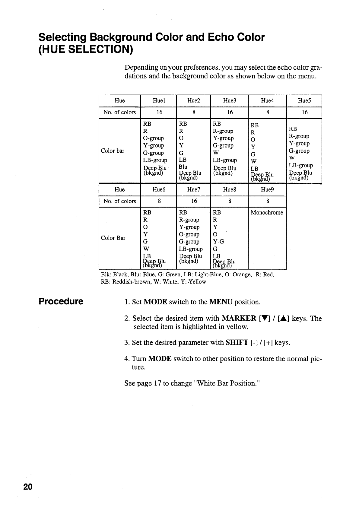
Selecting Background Color and Echo Color (HUE SELECTION)....................................... 20
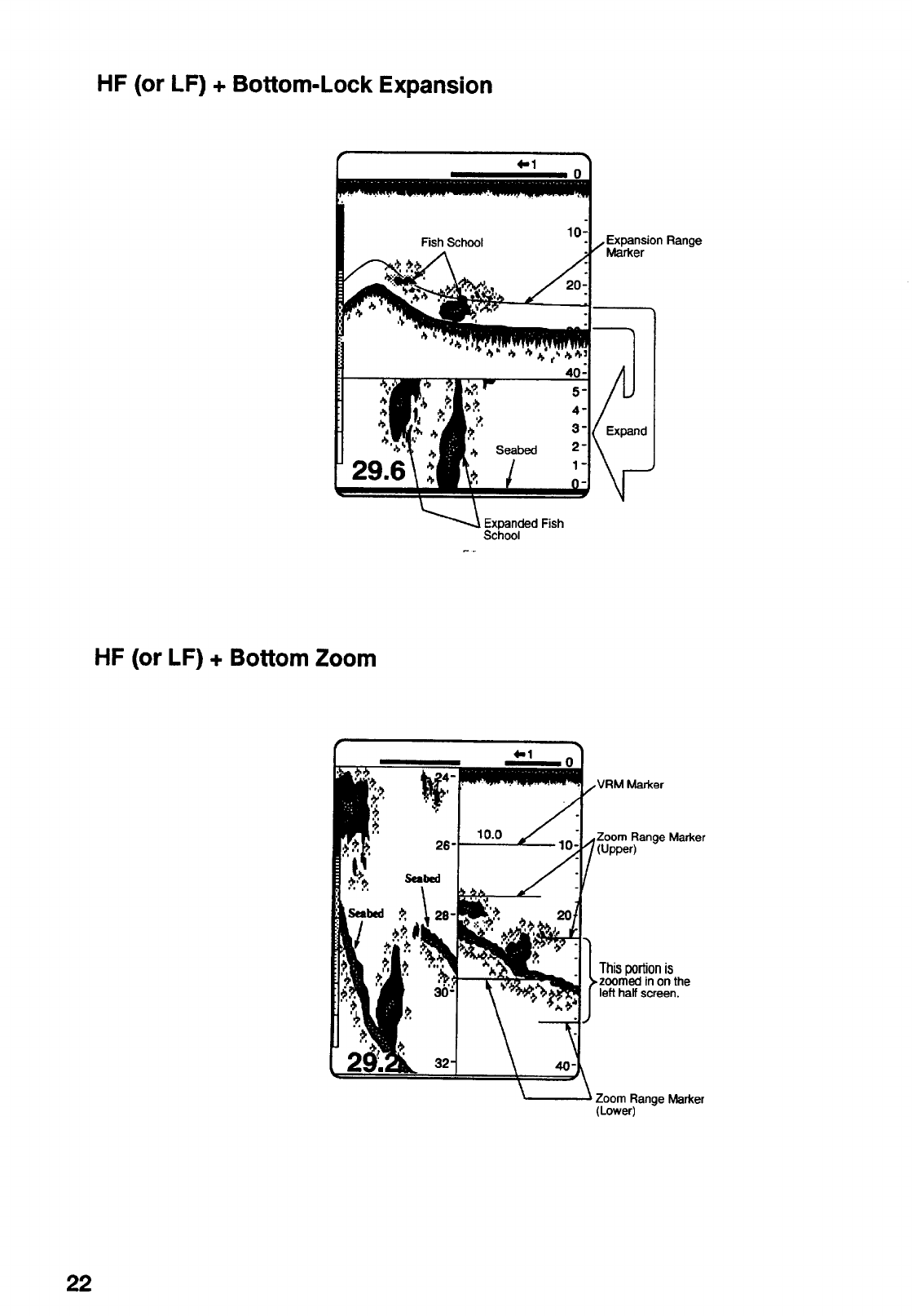
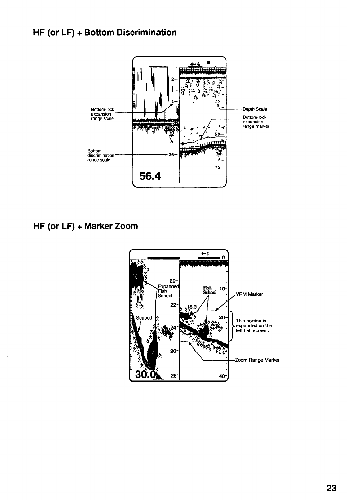
8.DISPLAYS ........................................................................................................ 21
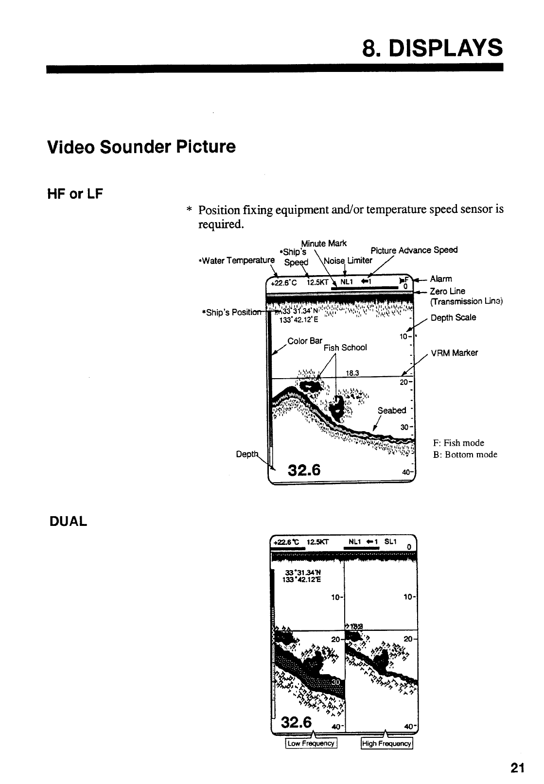
Video Sounder Picture........................................................................................................ 21
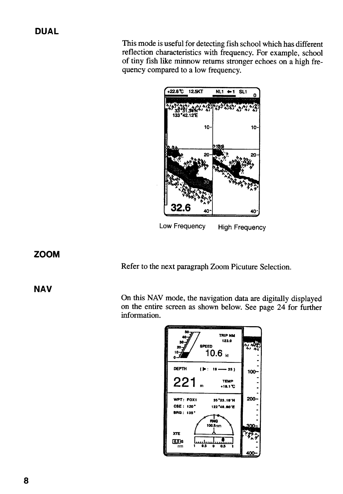
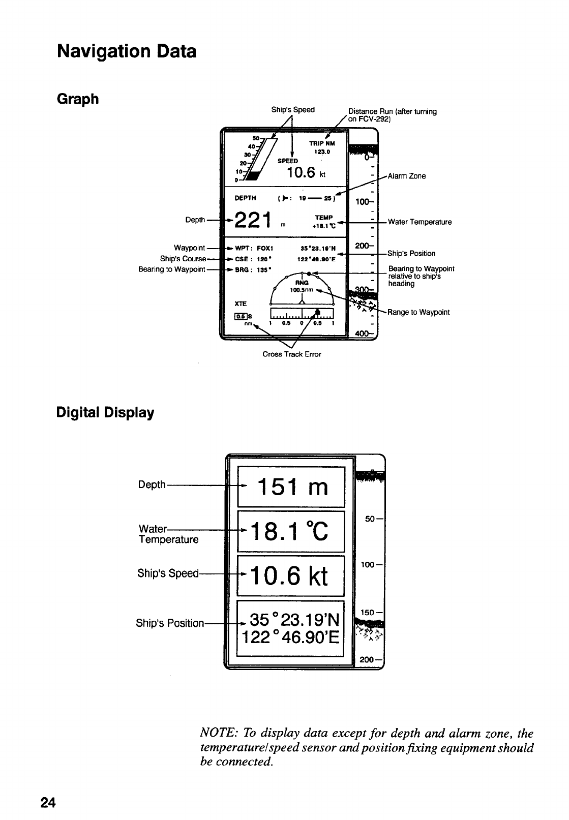
Navigation Data .................................................................................................................. 24
9.INTERPRETING THE DISPLAY ......................................................................25
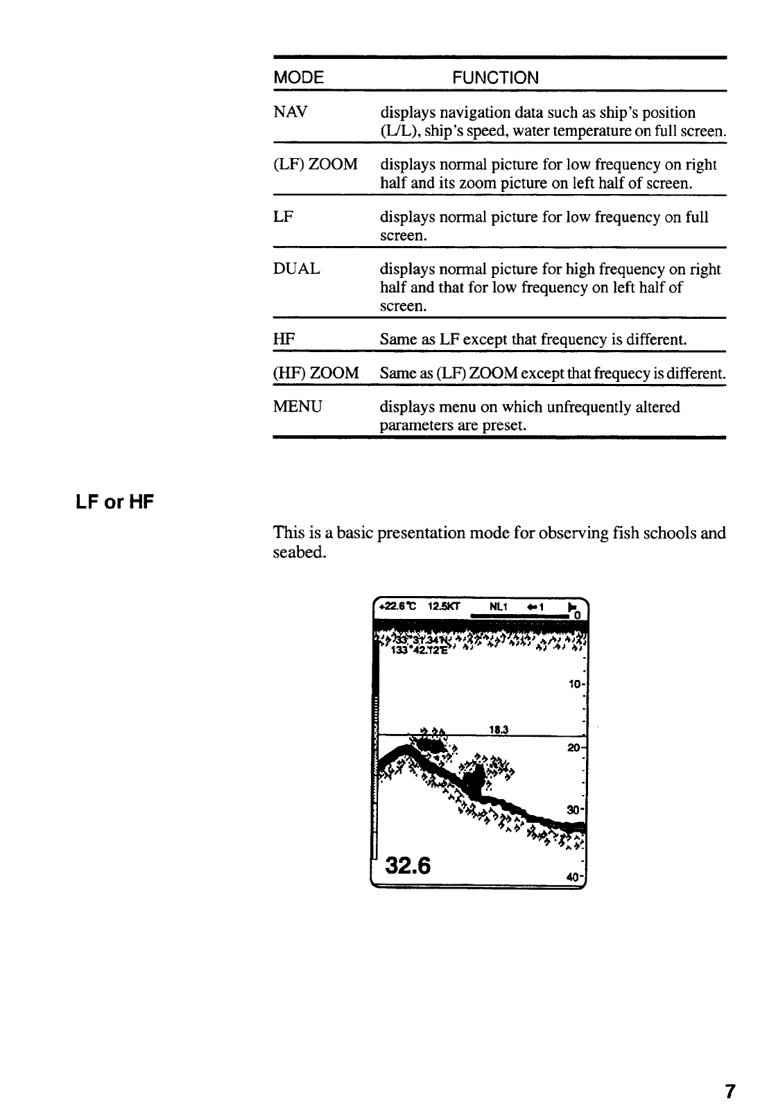
Frequency........................................................................................................................... 25
Detecting Area.................................................................................................................... 25
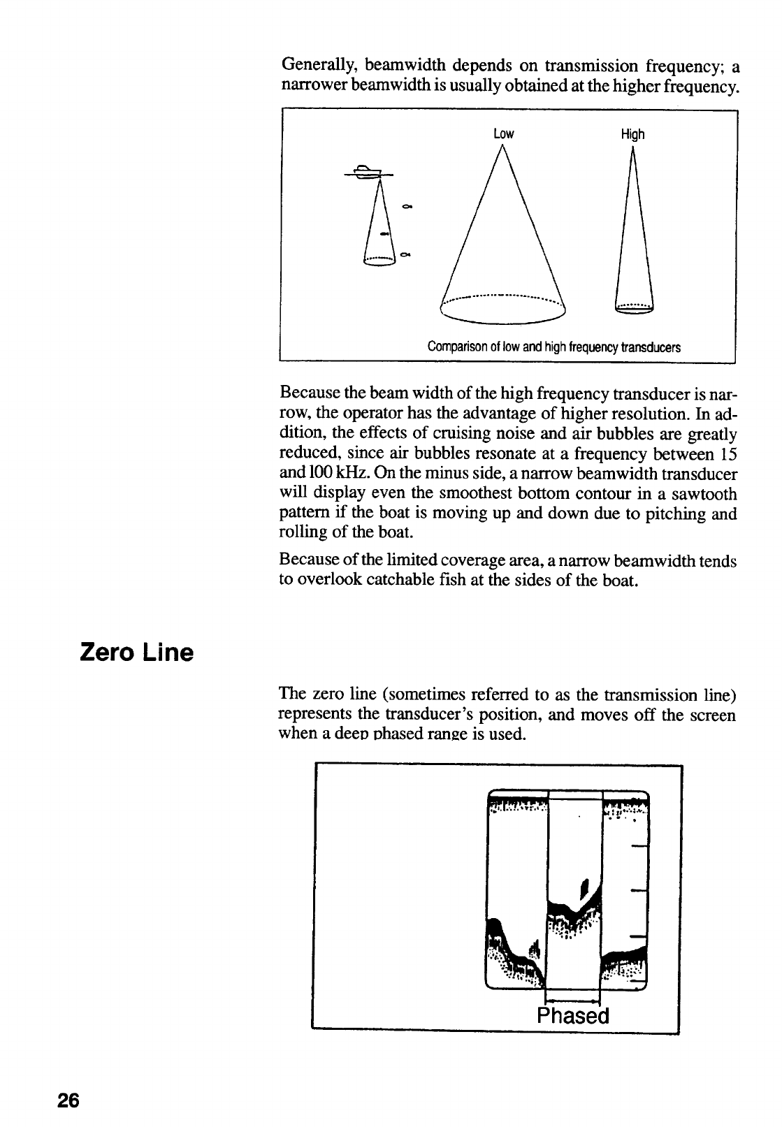
Zero Line ............................................................................................................................ 26
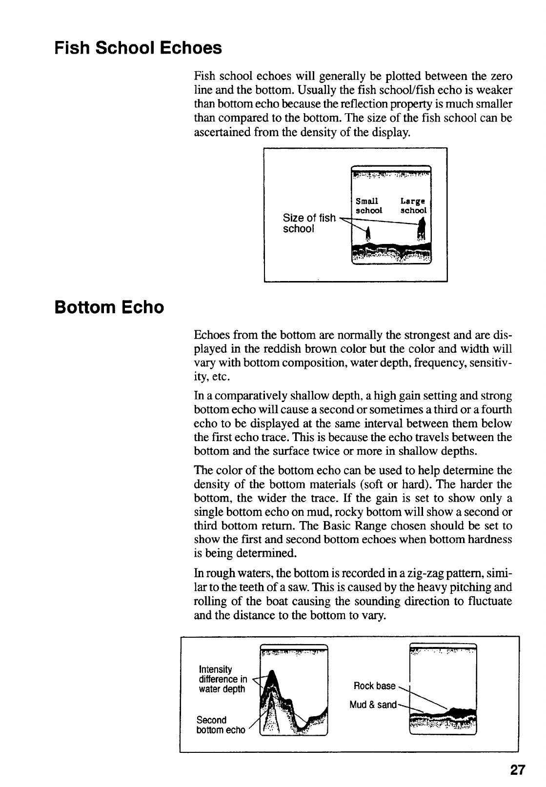
Fish School Echoes ............................................................................................................ 27
Bottom Echo ....................................................................................................................... 27
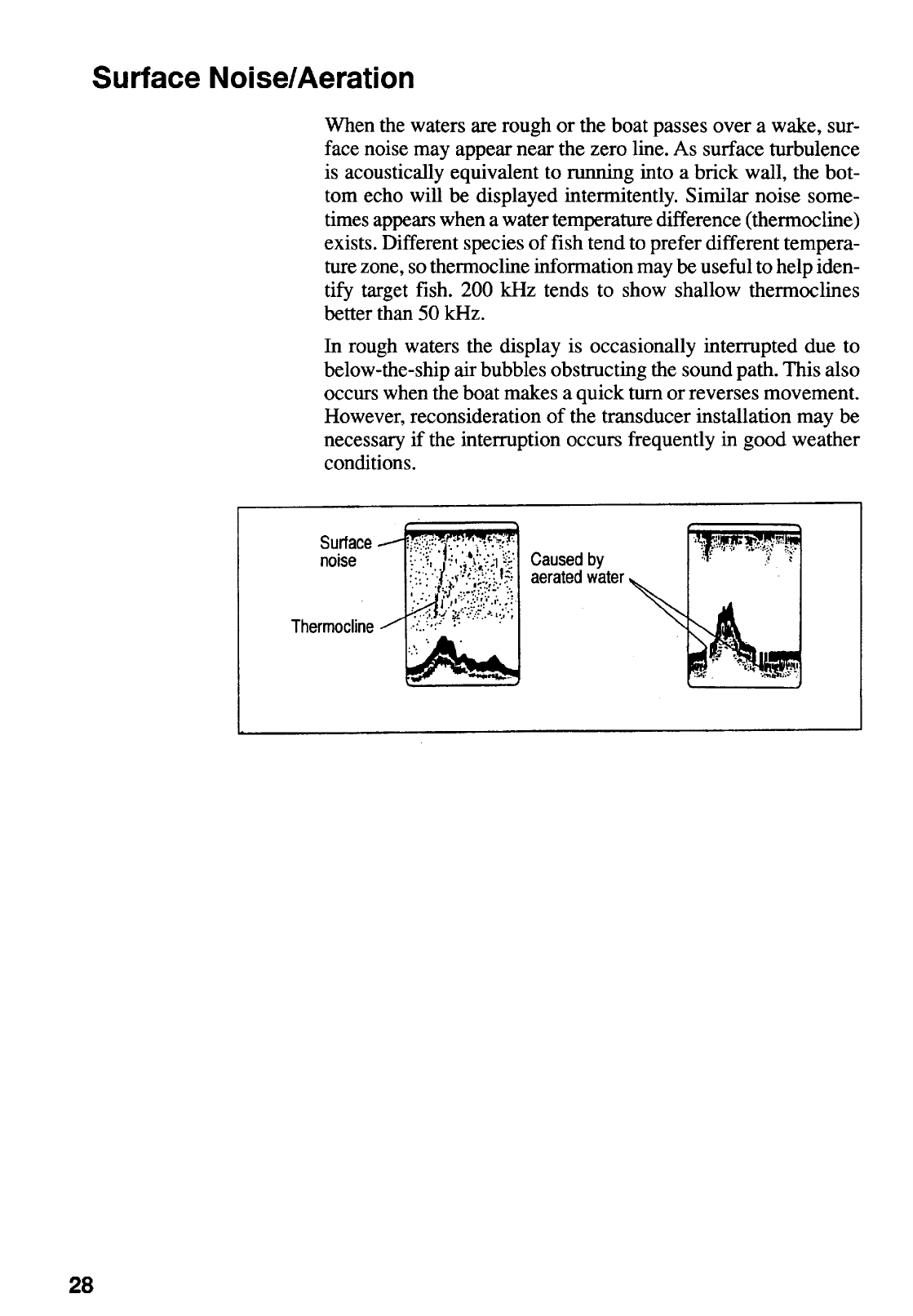
Surface Noise/Aeration ....................................................................................................... 28
viii
10.MAINTENANCE ............................................................................................. 29
Fuse Replacement ..............................................................................................................29
Cleaning..............................................................................................................................29
Maintenance of Transducer.................................................................................................30
11.TROUBLESHOOTING ................................................................................... 31
Basic Troubleshooting .........................................................................................................31
Diagnostic Self-Check .........................................................................................................33
Transducer Check ...............................................................................................................34
Speed/Temperature Sensor (Option) Check........................................................................34
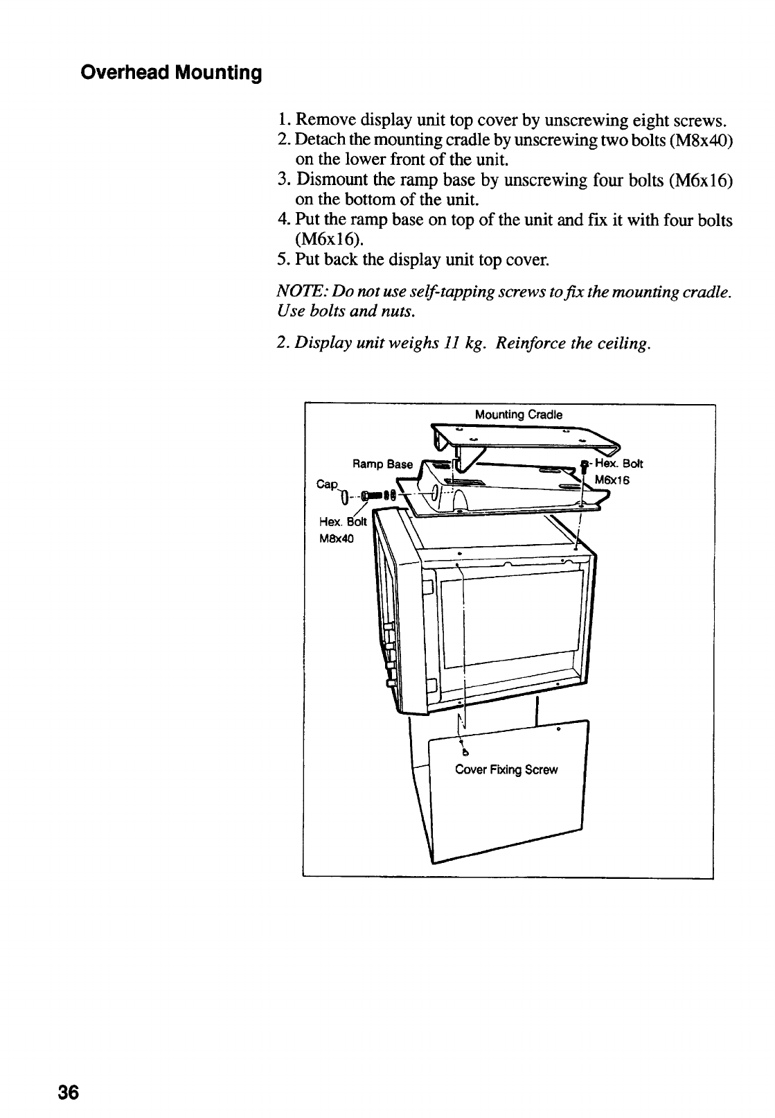
12.INSTALLATION.............................................................................................. 35
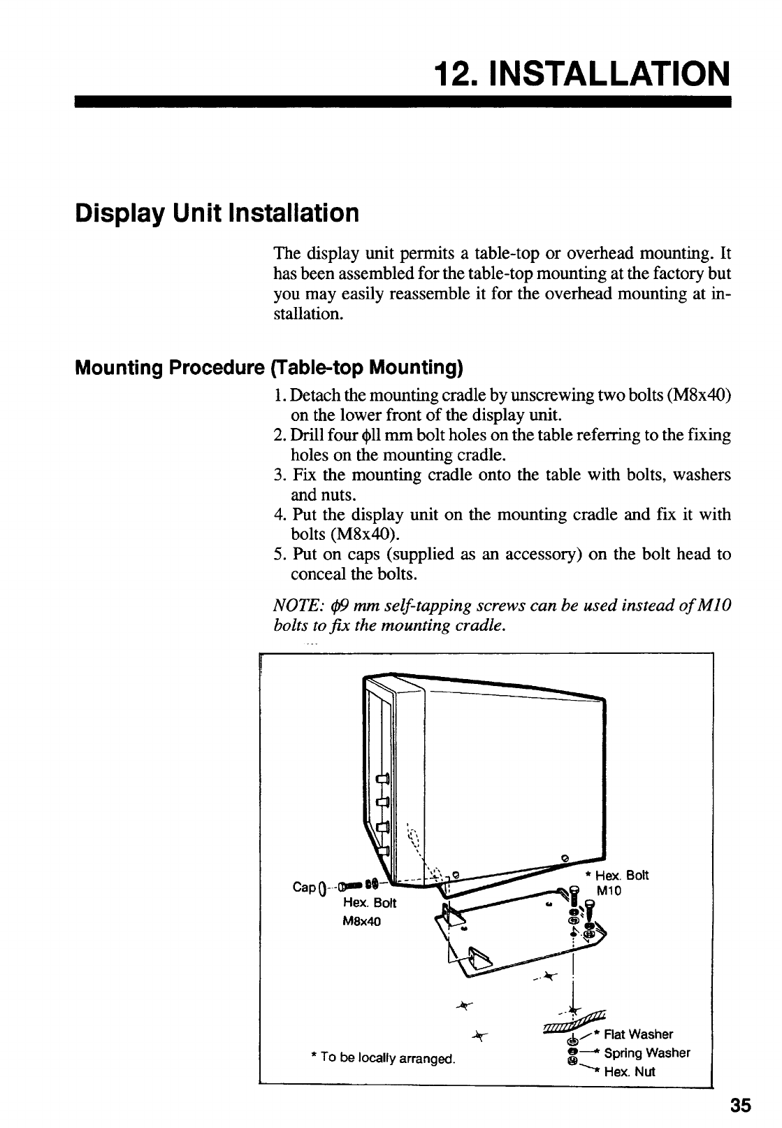
Display Unit Installation .......................................................................................................35
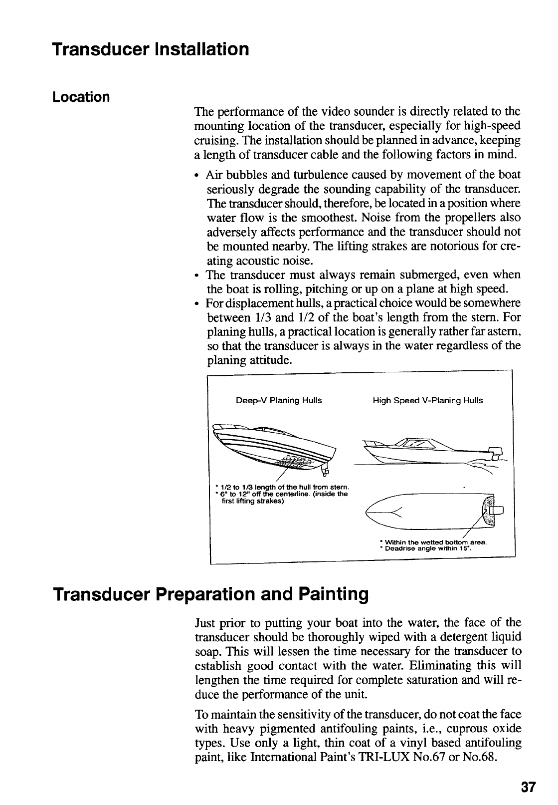
Transducer Installation ........................................................................................................37
Transducer Preparation and Painting ..................................................................................37
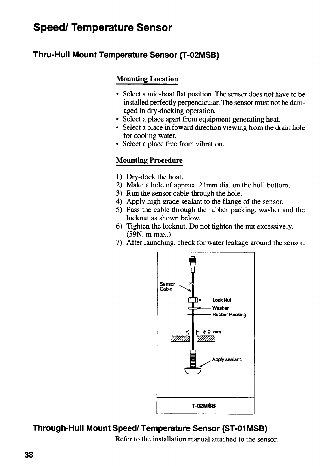
Speed/Temperature Sensor.................................................................................................38
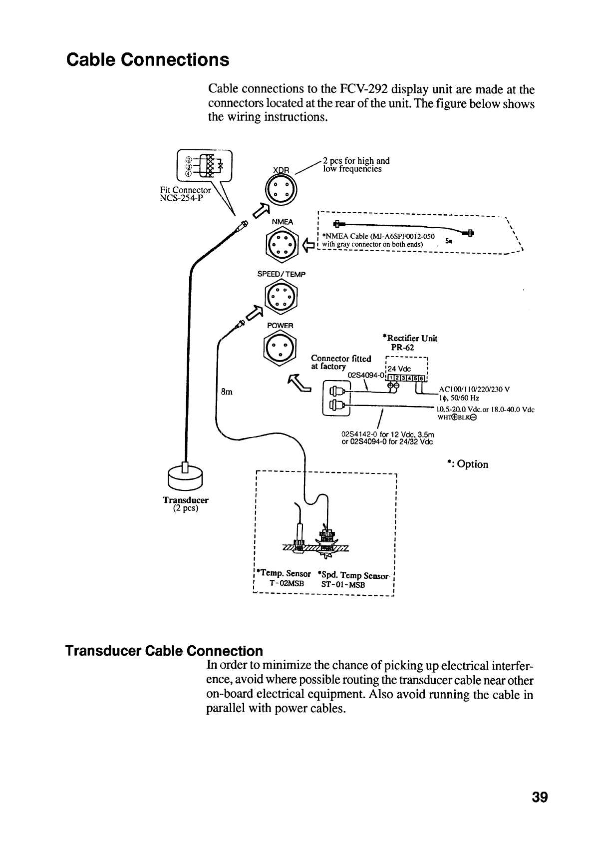
Cable Connections..............................................................................................................39
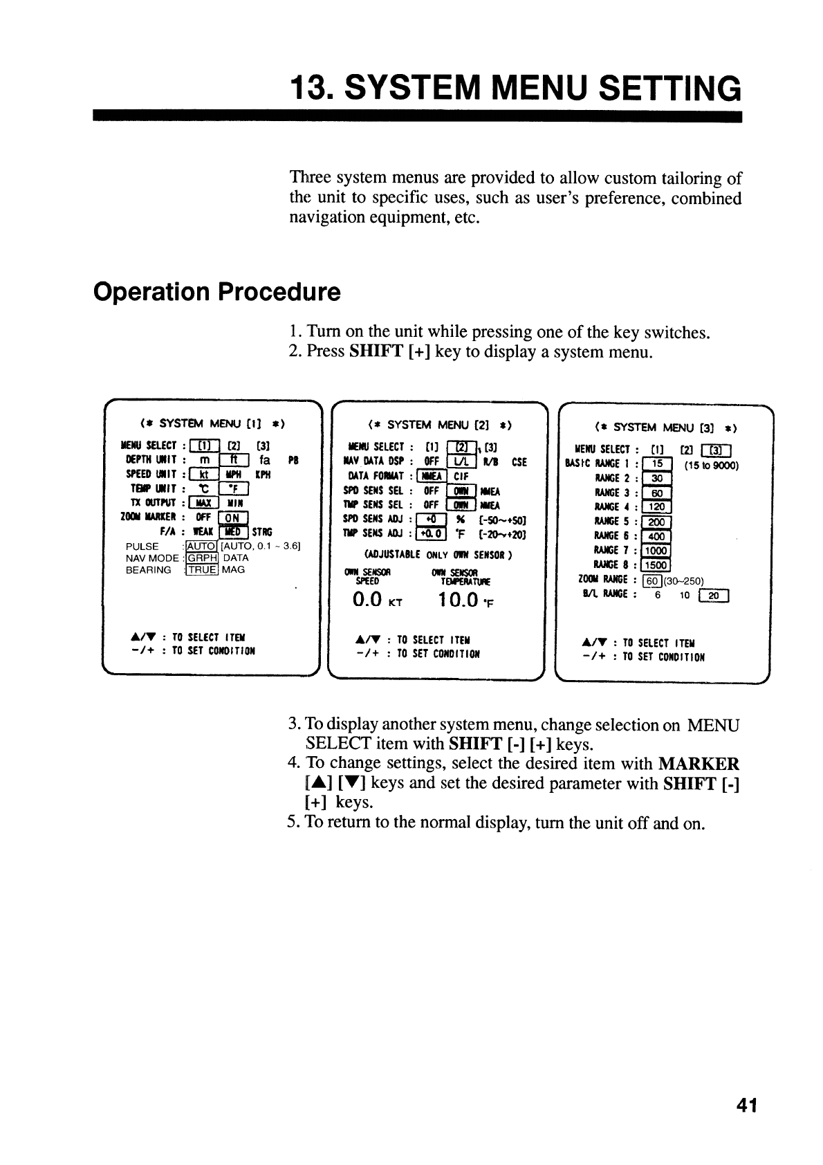
13.SYSTEM MENU SETTING............................................................................. 41
Operation Procedure ...........................................................................................................41
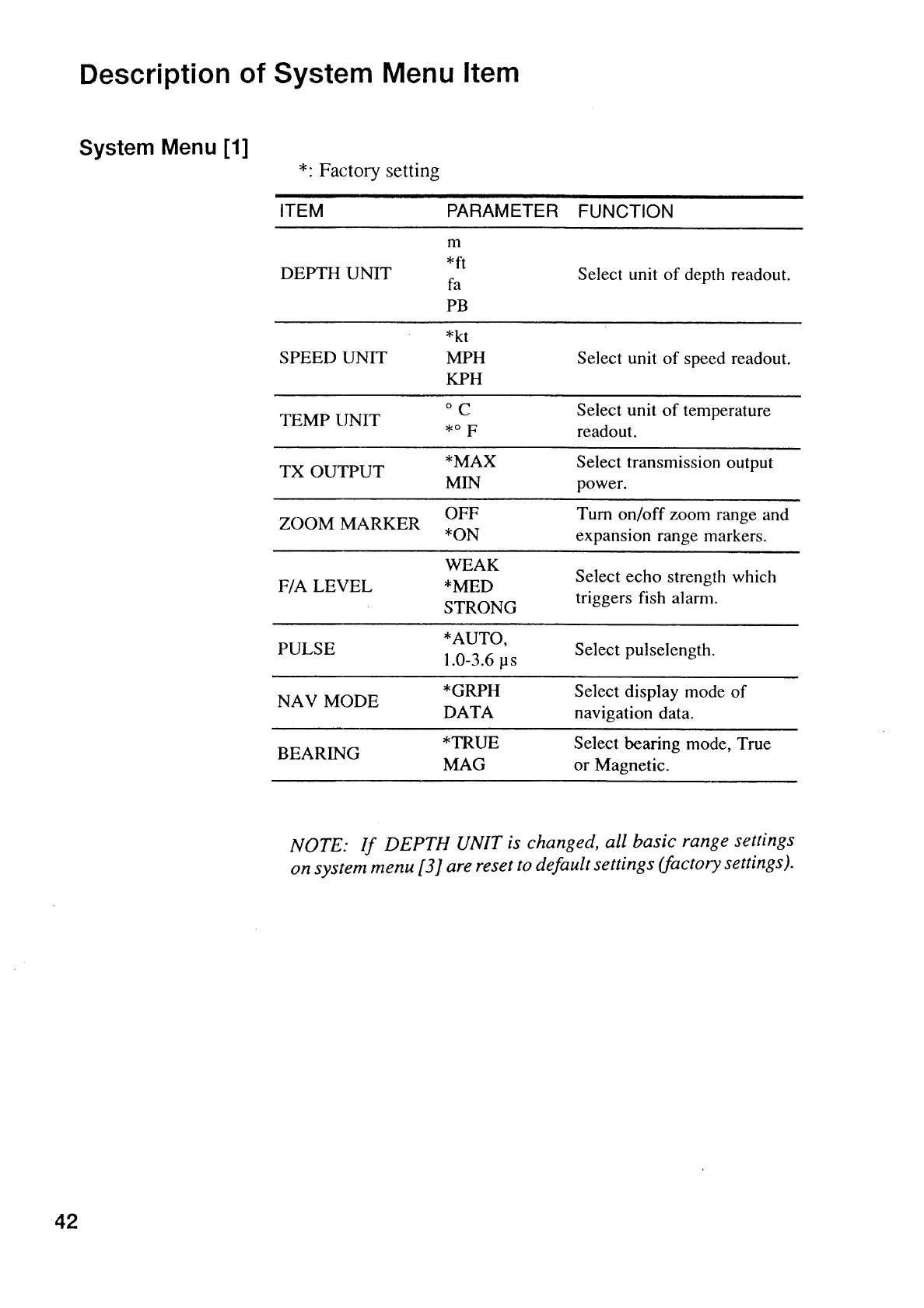
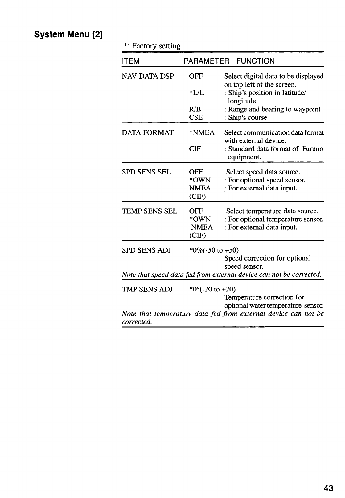
Description of System Menu Item........................................................................................42
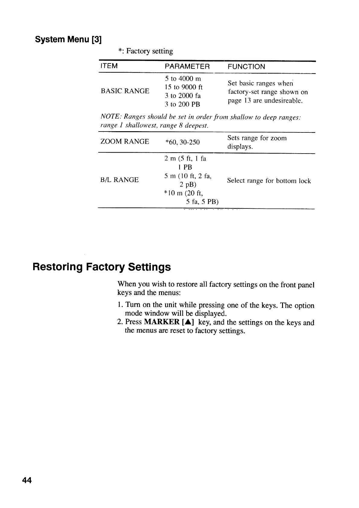
Restoring Factory Settings ..................................................................................................44
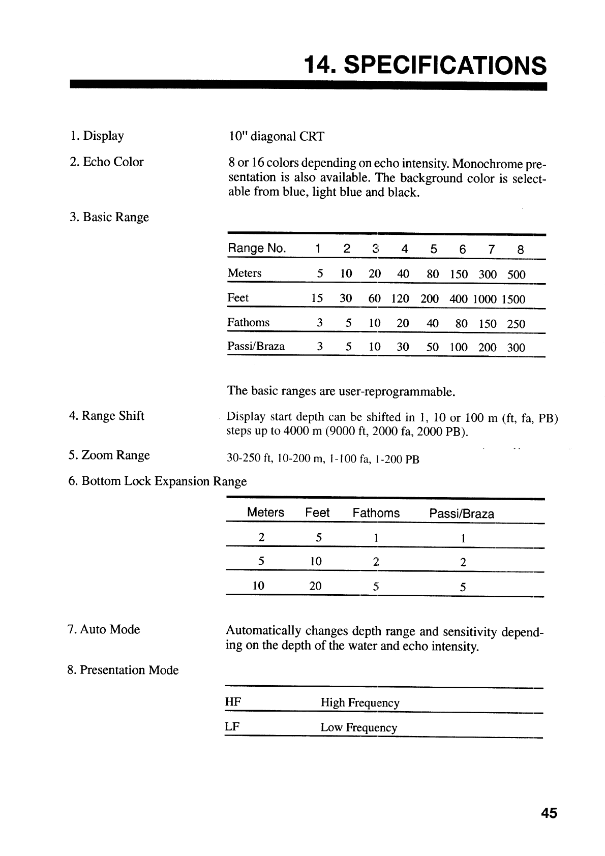
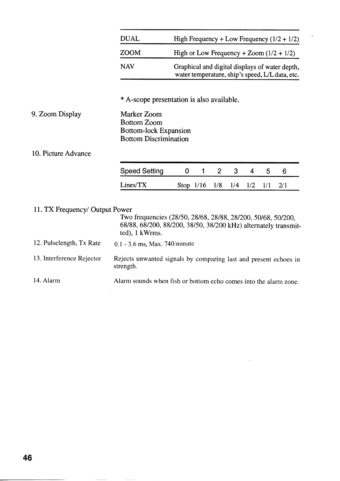
14.SPECIFICATIONS.......................................................................................... 45
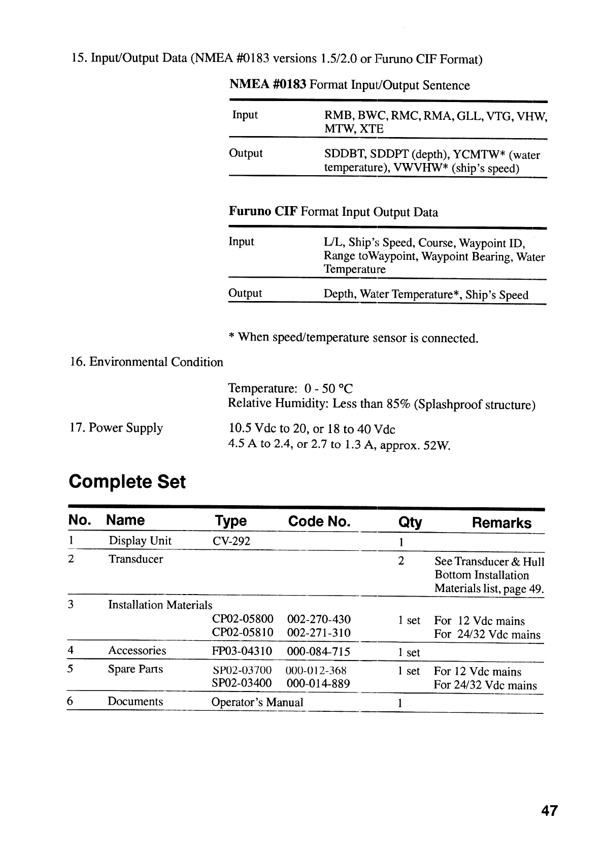
Complete Set.......................................................................................................................47
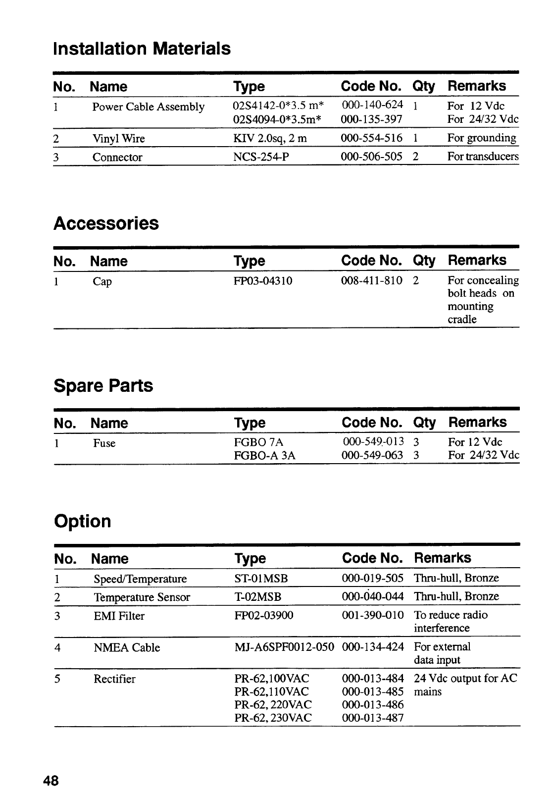
Installation Materials............................................................................................................48
Accessories.........................................................................................................................48
Spare Parts .........................................................................................................................48
Option..................................................................................................................................48
Transducer & Hull Bottom Installation Materials...................................................................49
APPENDIX
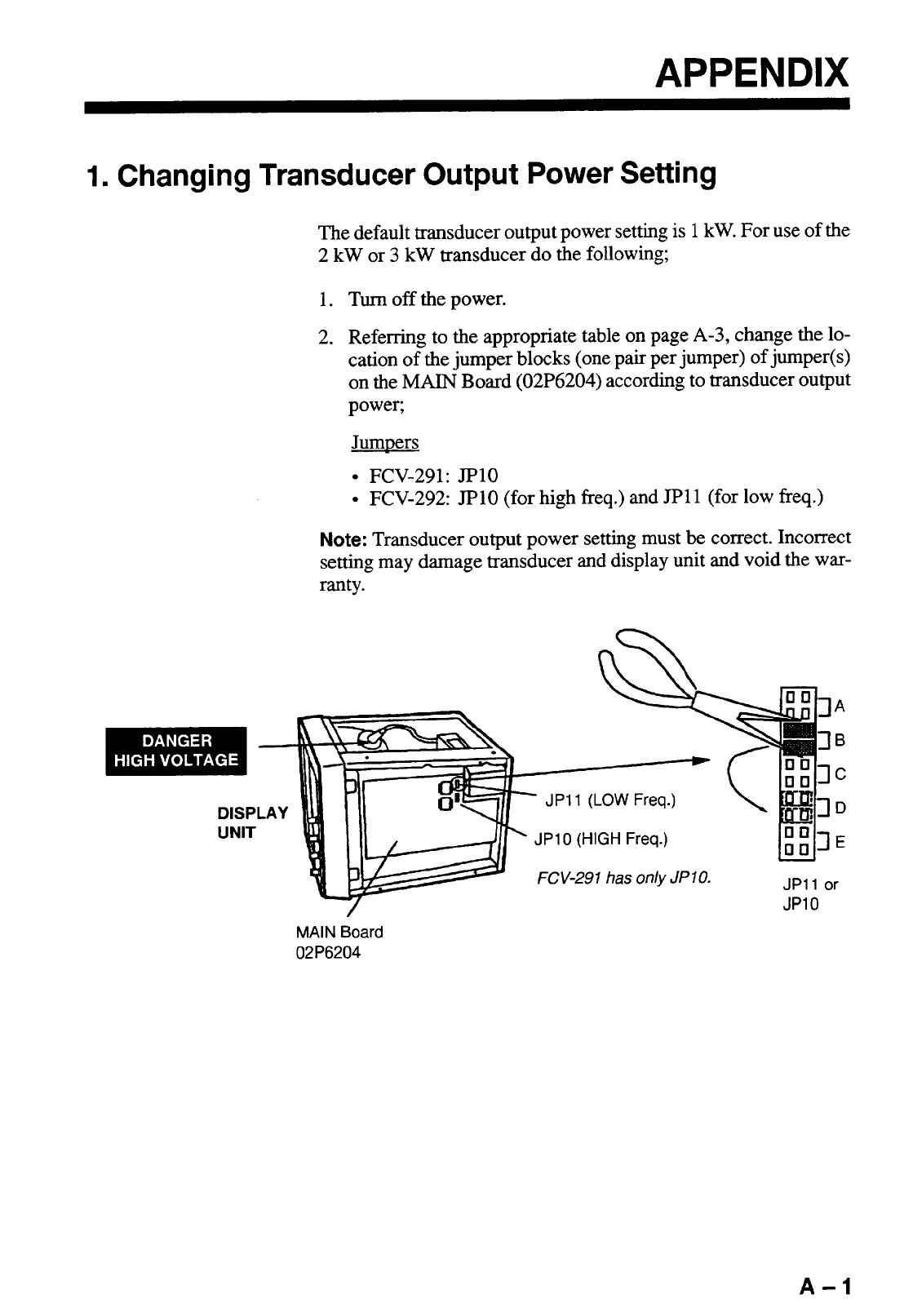
1. Changing Transducer Output Power Setting .......................................................................A-1
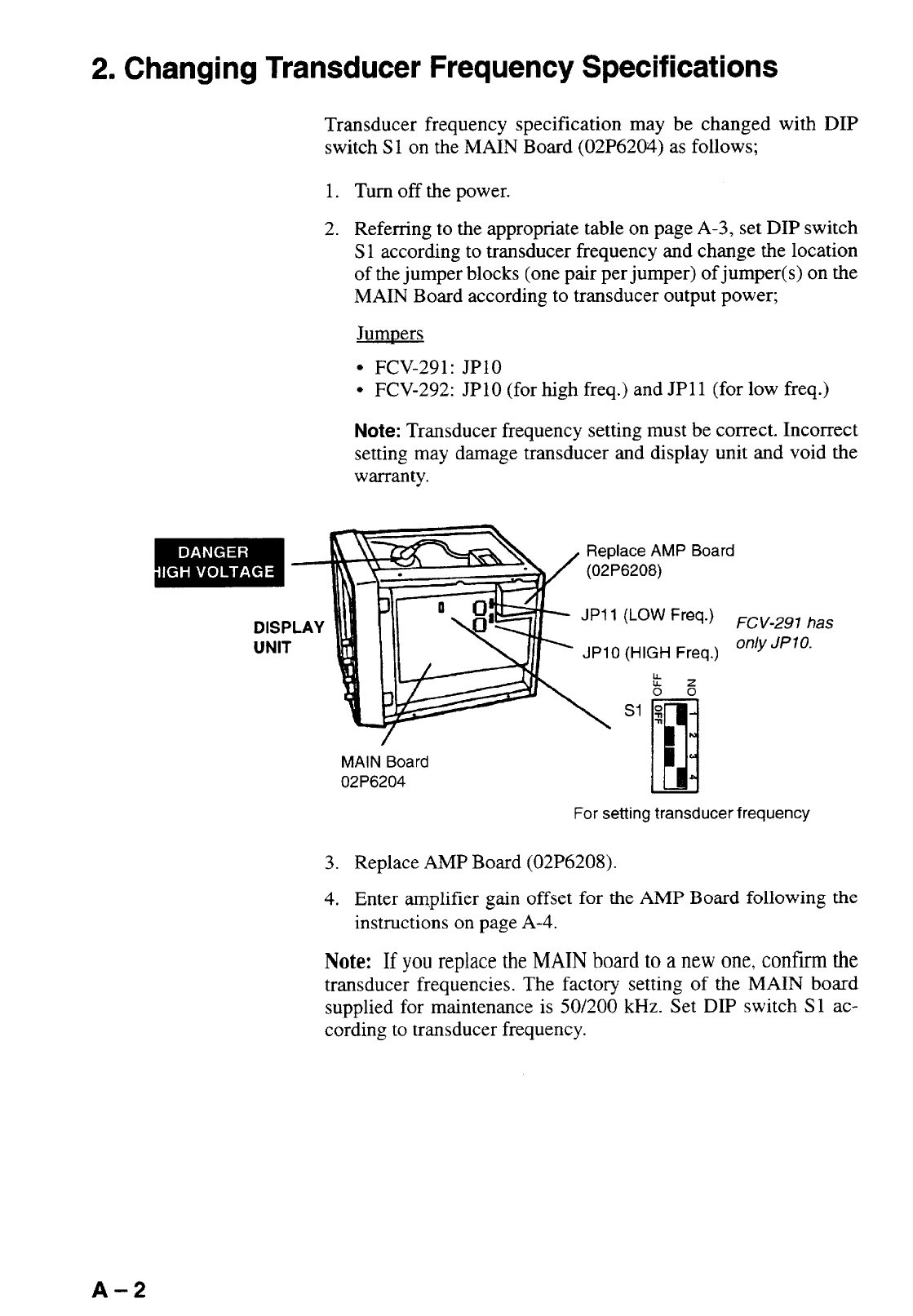
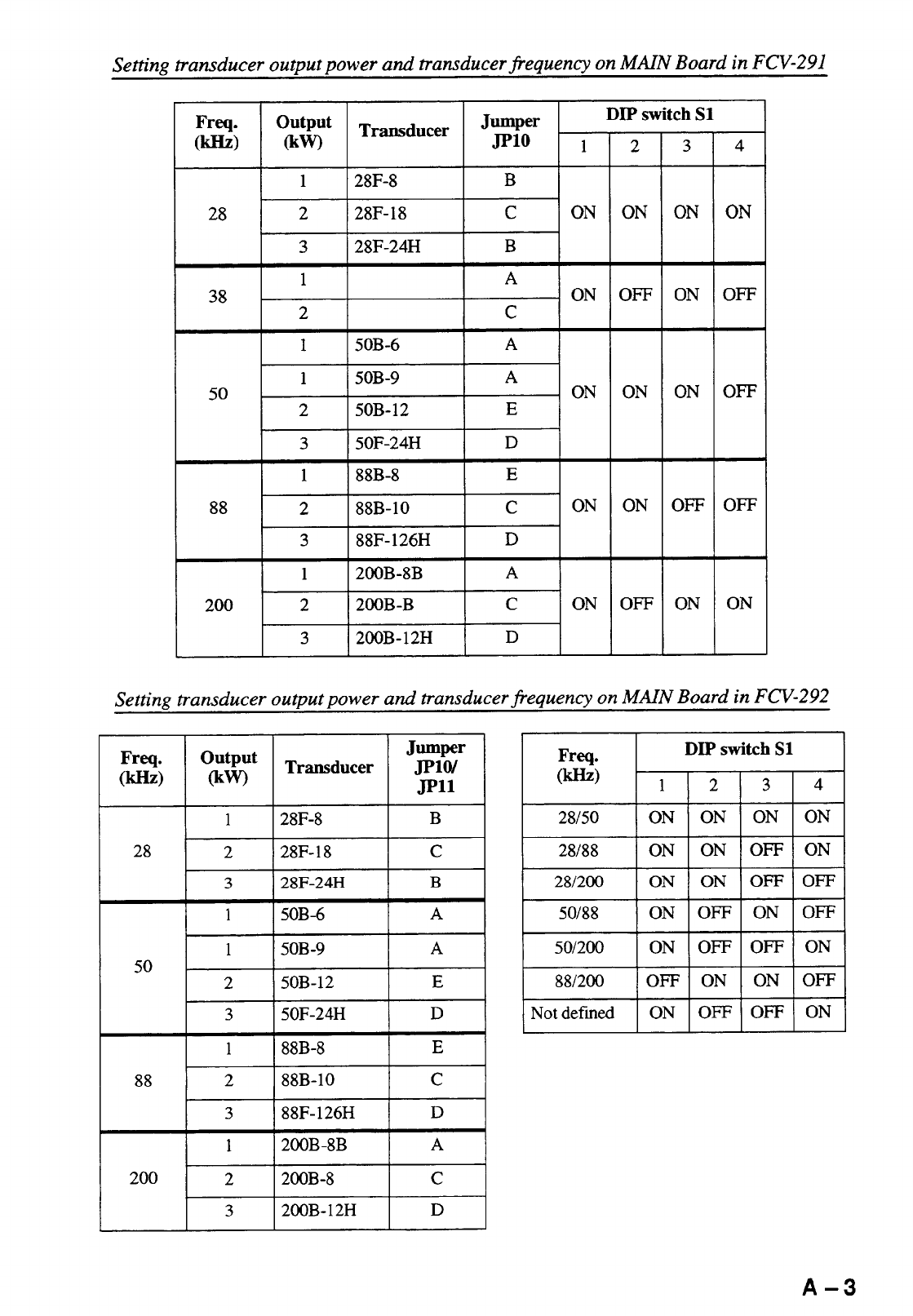
2. Changing Transducer Frequency Specifications ................................................................. A-2
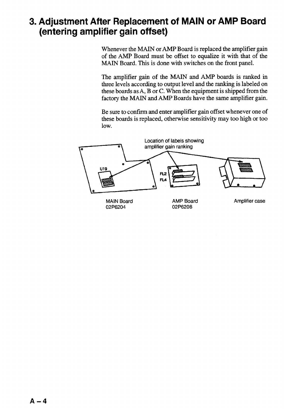
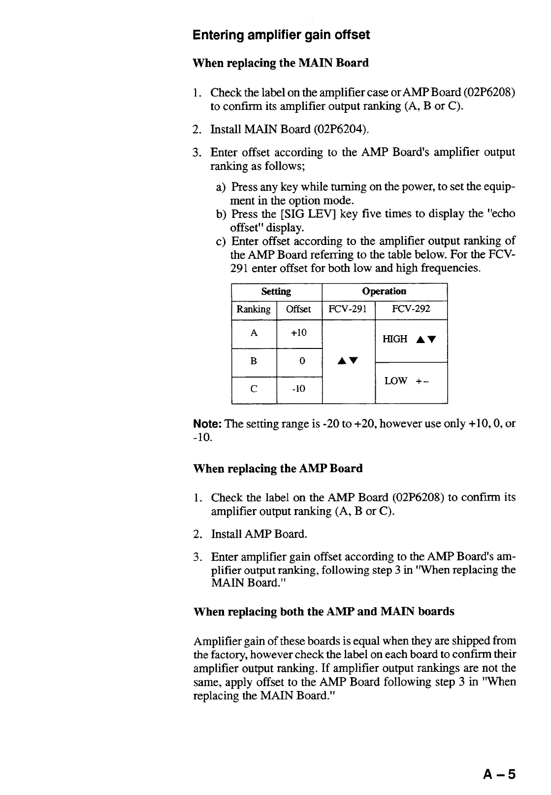
3. Adjustment After Replacement of MAIN or AMP Board (entering amplifier
gain offset) ..........................................................................................................................A-4
4. Transducer 50BL-12/50BL-24H........................................................................................... A-6
5. New BLT Transducers.........................................................................................................A-7
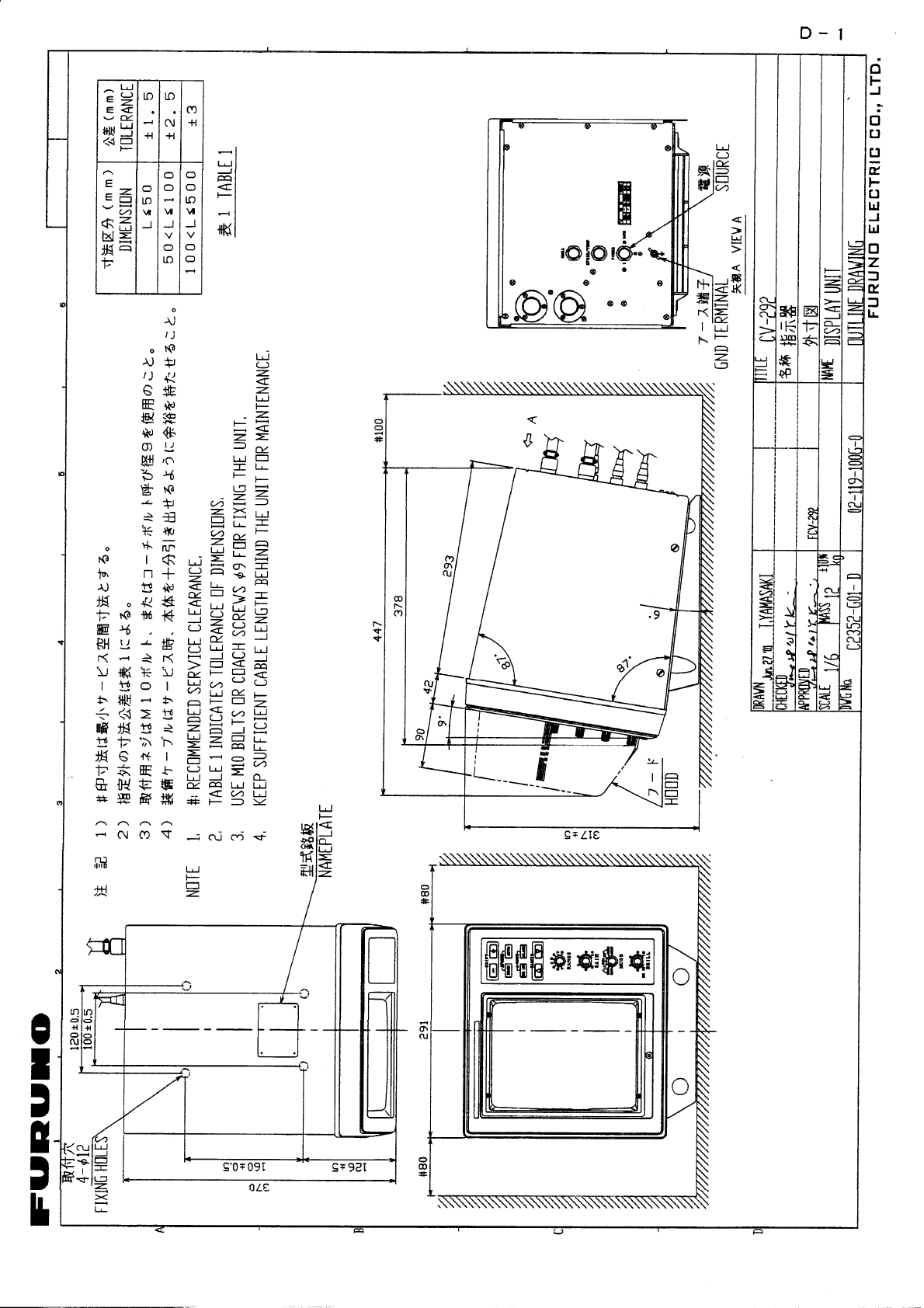
OUTLINE DRAWING ................................................................................ D-1
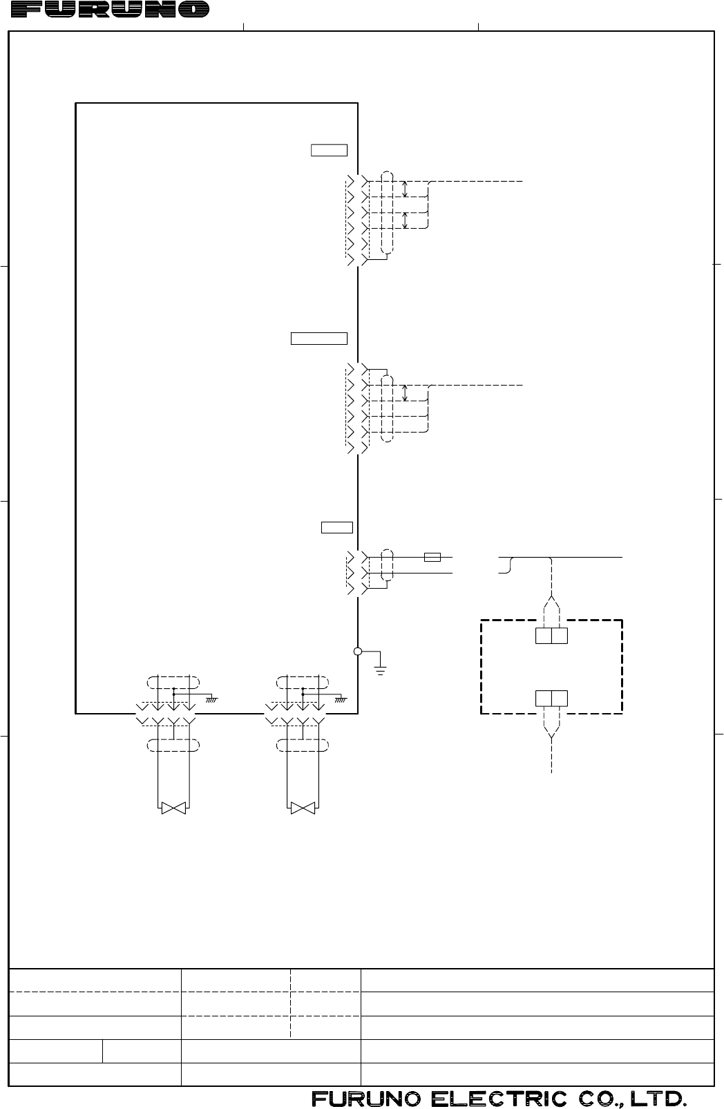
INTERCONNECTION DIAGRAM........................................................................... S-1

A-6
4.Transducer 50BL-12/50BL-24H
When using the transducer 50BL-12/50BL-24H, see this section.
50BL-12 code no.: 000-015-013
50BL-24H code no.: 000-015-040
Transducer, thru-hull pipe and tank list
Frequency
(kHz) Transducer
(Code No.) Hull
Material Tank
(Code No.) Fasten inside
hull (Code No.) Fasten outside
hull (Code No.)
Steel T-702
(000-015-041) TFB-5000
(000-015-206) -
50BL-12
FRP T-702F
(000-015-240) TRB-1000
(000-015-215) -
Steel T-694
(000-015-046) TFB-5000
(000-015-206) TFB-4000
(000-015-205)
50
50BL-24H
FRP T-694F
(000-015-242) TRB-1000
(000-015-215) -
Steel T-693
(000-015-044) TWB-6000
(000-015-207) TWB-7000
(000-015-209)
50/200 50BL-12/200B-8B
FRP T-693F
(000-015-241) TRB-1100
(000-015-218) -
Steel T-696
(000-015-048) TWB-6000
(000-015-207) TFB-7000
(000-015-209)
28/50 28F-24H/50BL-24H
FRP T-696F
(000-015-244) TWB-1100
(000-015-218) -
Steel T-697
(000-015-239) TWB-6000
(000-015-207) TFB-7000
(000-015-209)
50/88 50BL-24H/88F-126H
FRP T-697F
(000-015-245) TWB-1100
(000-015-218) -
Steel T-695
(000-015-047) TWB-6000
(000-015-207) TFB-7000
(000-015-209)
50/200 50BL-24H/200B-12H
FRP T-695F
(000-015-243) TRB-1100
(000-015-218) -
Setting
For the locations of JP10 and JP11, see page A-1.
Board Frequency (kHz) Output (kW) Transducer JP10 and JP11 setting
2 5BL-12 B 02P6204
MAIN 50 3 50BL-24H D
S1
Board Frequency (kHz) 1 2 3 4
28/50 ON ON ON ON
50/88 ON OFF ON OFF
02P6204
MAIN 50/200 ON OFF OFF ON

A-7
5.New BLT Transducers
A new type BLT transducer (Bolt-clamp Langevin Transducer) has been developed for this
echo sounder. The BLT transducer has large bandwidth, good sound efficiency, compact
structure and is reinforced for protection against slamming.
28BL-6HR code no.: 000-015-081
28BL-12HR code no.: 000-015-082
38BL-9HR code no.: 000-015-083
38BL-15HR code no.: 000-015-092
50BL-12HR code no.: 000-015-093
50BL-24HR code no.: 000-015-094
Transducer, thru-hull pipe and tank list
Frequency
(kHz) Transducer Hull
Material Tank
(Code No.) Fasten inside
hull (Code No.) Fasten outside
hull (Code No.)
Steel T-693
(000-015-044) TWB-6000 (2)
(000-015-207) TFB-7000 (2)
(000-015-209)
28/200 28BL-6HR/200B-8B
FRP T-693F
(000-015-241) TRB-1100 (2)
(000-015-219) -
Steel T-693
(000-015-044) TWB-6000 (2)
(000-015-207) TFB-7000 (2)
(000-015-209)
38/200 38BL-9HR/200B-8B
FRP T-693F
(000-015-241) TRB-1100 (2)
(000-015-219) -
Steel T-693
(000-015-044) TWB-6000 (2)
(000-015-207) TFB-7000 (2)
(000-015-209)
50/200 50BL-12HR/200B-8B
FRP T-693F
(000-015-241) TRB-1100 (2)
(000-015-219) -
Steel T-681
(000-015-849) TWB-6000 (2)
(000-015-207) TFB-7000 (2)
(000-015-209)
28/38 28BL-12HR/38BL-15HR
FRP T-681F
(000-015-850) TRB-1100 (2)
(000-015-219) -
Steel T-681
(000-015-849) TWB-6000 (2)
(000-015-207) TFB-7000 (2)
(000-015-209)
28/50 28BL-12HR/50BL-24HR
FRP T-681F
(000-015-850) TRB-1100 (2)
(000-015-219) -
Steel T-681
(000-015-849) TWB-6000 (2)
(000-015-207) TFB-7000 (2)
(000-015-209)
38/50 38BL-15HR/50BL-24HR
FRP T-681F
(000-015-850) TRB-1100 (2)
(000-015-219) -
Steel T-682
(000-015-851) TWB-6000 (2)
(000-015-207) TFB-7000 (2)
(000-015-209)
28/88 28BL-12HR/88F-126H
FRP T-682F
(000-015-852) TRB-1100 (2)
(000-015-219) -

NEW BLT TRANSDUCERS
A-8
Steel T-682
(000-015-851)
TWB-6000 (2)
(000-015-207)
TFB-7000 (2)
(000-015-209)
38/88 38BL-15HR/88F-126H
FRP T-682F
(000-015-852)
TRB-1100 (2)
(000-015-219) -
Steel T-682
(000-015-851) TWB-6000 (2)
(000-015-207) TFB-7000 (2)
(000-015-209)
50/88 50BL-24HR/88-126H
FRP T-682F
(000-015-852) TRB-1100 (2)
(000-015-219) -
Steel T-683
(000-015-853) TWB-6000 (2)
(000-015-207) TFB-7000 (2)
(000-015-209)
28/200 28BL-12HR/200B-12H
FRP T-683F
(000-015-854) TRB-1100 (2)
(000-015-219) -
Steel T-683
(000-015-853) TWB-6000 (2)
(000-015-207) TFB-7000 (2)
(000-015-209)
38/200 38BL-15HR/200B-12H
FRP T-683F
(000-015-854) TRB-1100 (2)
(000-015-219) -
Steel T-683
(000-015-853) TWB-6000 (2)
(000-015-207) TFB-7000 (2)
(000-015-209)
50/200 50BL-24HR/200B-12H
FRP T-683F
(000-015-854) TRB-1100 (2)
(000-015-219) -
Steel T-683
(000-015-853) TWB-6000 (2)
(000-015-207) TFB-7000 (2)
(000-015-209)
28/150 28BL-12HR/150B-12H
FRP T-683F
(000-015-854) TRB-1100 (2)
(000-015-219) -
Steel T-683
(000-015-853) TWB-6000 (2)
(000-015-207) TFB-7000 (2)
(000-015-209)
38/150 38BL-15HR/150-12H
FRP T-683F
(000-015-854) TRB-1100 (2)
(000-015-219) -
Steel T-683
(000-015-853) TWB-6000 (2)
(000-015-207) TFB-7000 (2)
(000-015-209)
38/150 50BL-24HR/156-12H
FRP T-683F
(000-015-854) TRB-1100 (2)
(000-015-219) -

NEW BLT TRANSDUCERS
A
-9
Setting
For the locations of JP10 and JP11, see page A-1.
Board Frequency (kHz) Output (kW) Transducer JP10 and JP11 setting
2 28BL-6HR B
28 3 28BL-12HR C
2 38BL-9HR C
38 3 38BL-15HR E
2 50BL-12HR D
02P6204
MAIN
50 3 50BL-24HR E
S1
Board Frequency (kHz) 1 2 3 4
28/50 ON ON ON ON
38/50 OFF ON ON ON
50/88 ON OFF ON OFF
02P6204
MAIN
50/200 ON OFF OFF ON
kg
321
A
D
C
B
FCV-291/292
INTERCONNECTION DIAGRAM
COLOR VIDEO SOUNDER
相互結線図
カラー魚群探知機
C2351-C01- F
DWG.No.
SCALE
APPROVED
CHECKED
DRAWN
MASS
名称
NAME
TITLE
Sep. 30 '02
T.YAMASAKI
*1)造船所手配
*2)工場にて接続済み
*3)FCV-292のみ *3: ONLY FOR FCV-292.
*2: FITTED AT FACTORY.
*1: SHIPYARD SUPPLY.
NOTE
注記
21
56
MJ-A6SPFD
DISPLAY UNIT
CV-291/292
指示器
NAV AID
航法装置
船速・水温センサー
POWER
NMEA
SPEED/TEMP
MJ-A6SPFD
6
5
4
3
2
1
SHIELD
NC
RXD-C
RXD-H
TXD-C
TXD-H
GND
(-)
(+)
GND
クロ BLK
シロ WHT
P
6
5
4
3
2
18m
+10V
SPD
VTH-C
VTH-H
12/24-32 VDC
SHIP'S MAINS
船内電源
1
3
2
DPYC-1.5 *1
PR-62
RECTIFIER
整流器
43214321
NCS-254PNCS-254P
TX-HTX-L
J1 J2
XDCRXDCR
*3
送受波器送受波器
50/60 Hz, 1φ
100/110/220 VAC
IV-2.0SQ
GND
J3
J5
J4 MJ-A6SPF0012,5m
P
P
SPEED/TEMP SENSOR
ST-01MSB
T-02MSB
Oct. 1 '02
Y.KIMURA
MJ-A3SPF0013,3.5m,φ6
MJ-A3SPFD 7A: 12V
3A: 24/32V
FUSE
Oct. 1, '02
S-1
