Furuno Fe 700 Users Manual
FE-700 to the manual 172558e7-00ee-4855-97a5-2eb2076b8d9c
2015-02-02
: Furuno Furuno-Fe-700-Users-Manual-428954 furuno-fe-700-users-manual-428954 furuno pdf
Open the PDF directly: View PDF ![]() .
.
Page Count: 44
- SAFETY INSTRUCTIONS
- CONTENTS
- FOREWORD
- SYSTEM CONFIGURATION
- SPECIFICATIONS
- 1 OPERATION
- 2 MENU OPERATION
- 3 SYSTEM MENU
- 4 ECHO QUALITY SETTING
- 5 OPERATION OF DIGITAL DEPTH INDICATOR FE-720 (OPTION)
- 6 MAINTENANCE, TROUBLESHOOTING
- 7 MENU TREE
- 8 DIGITAL INTERFACE (IEC 61162-1 EDITION 2)
- 9 PARTS LOCATION, PARTS LIST
- ELECTRICAL PARTS LIST
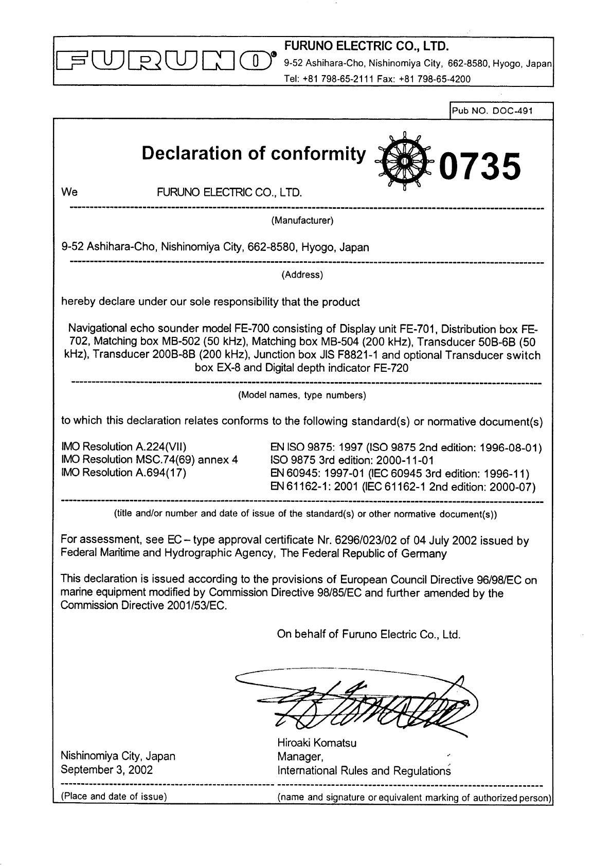
- Declaration of conformity

NAVIGATIONAL ECHO SOUNDER
FE-700

Your Local Agent/DealerYour Local Agent/Dealer
9-52 Ashihara-cho,9-52 Ashihara-cho,
Nishinomi
y
a 662-8580, JAPANNishinomi
y
a 662-8580, JAPAN
Tele
p
hone :Tele
p
hone : 0798-65-21110798-65-2111
FaxFax 0798-65-42000798-65-4200
::
F
IRST EDITION :
F
IRST EDITION : JANJAN.. 20002000
Printed in JapanPrinted in Japan
A
ll ri
g
hts reserved.
A
ll ri
g
hts reserved.
QQ :: DECDEC.. 15, 200415, 2004
Pub. No.Pub. No. OME-23660OME-23660
*
00080890804
*
*
00080890804
*
*
00080890804
*
*
00080890804
*
(( YOSHYOSH )) FE-700FE-700 * 0 0 0 8 0 8 9 0 8 0 4 ** 0 0 0 8 0 8 9 0 8 0 4 *
*
OME
23660
Q
00
*
*
OME
23660
Q
00
*
*
OME
23660
Q
00
*
*
OME
23660
Q
00
*
* O M E 2 3 6 6 0 Q 0 0 ** O M E 2 3 6 6 0 Q 0 0 *
i
SAFETY INSTRUCTIONS
Do not power the equipment when the
transducer is in air.
The transducer may become damaged.
The TFT LCD is constructed using the
latest LCD techniques, and displays
99.99% of its pixels. The remaining 0.01%
of the pixels may drop out or blink, how-
ever this is not an indication of malfunc-
tion.
About the TFT LCD
WARNING
Immediately turn off the power at the
switchboard if water leaks into the
equipment.
Continued use of the equipment can cause
fire or electrical shock. Contact a FURUNO
agent for service.
Do not disassemble or modify the
equipment.
Fire, electrical shock or serious injury can
result.
Immediately turn off the power at the
switchboard if the equipment is emitting
smoke or fire.
Continued use of the equipment can cause
fire or electrical shock. Contact a FURUNO
agent for service.
Make sure no rain or water splash leaks
into the equipment.
Fire or electrical shock can result if water
leaks in the equipment.
Use the proper fuse.
Use of a wrong fuse can result in equipment
damage and void the warranty.
ELECTRICAL SHOCK HAZARD
Do not open the equipment.
Only qualified personnel
should work inside the
equipment.
WARNING LABEL
A warning label is attached to the equip-
ment. Do not remove the label. If the
label is missing or illegible, contact
a FURUNO agent or dealer.
WARNING
To avoid electrical shock, do not
remove cover. No user-serviceable
parts inside.
Name: Warning Label (1)
Type: 86-003-1011-1
Code No.: 100-236-231
CAUTION

ii
RECORD OF MODIFICATIONS IN THIS OPERATOR’S MANUAL
Pub No. Software (Prog No.) Outline of changes in Operator’s manual
Publicized for
submission to
type test by BSH
(Feb/2000)
Display Unit
02522970-01
Digital Depth Indicator
65-5-0100-001
displayed at switch-on
(Subject to change by the type approval authorities.)
(Subject to change by the type approval authorities.)
OME-23660-F
Dec/2000
Digital Depth Indicator
65-5-0100-003
Changed [Unit] key to [*] and the related part of software.
OME-23660-G
Apr/2001
Display Unit
02522970-02
(Serial no. 2232-0618 and
after)
Added TRANSDUCER SETTING option in the
EXTENSION MODE menu.
Added KEEL DISTANCE option in the SYSTEM MENU3.
OME-23660-H
May/2001
---- Modified errors.
OME-23660-K
Apr/2002 Display Unit
02522970-03
Modified to conform with IEC 61162-1 Edition 2.
OME-23660-Q
Dec/2004
Display Unit
02522970-04
Deleted KEEL DISTANCE option in the SYSTEM
MENU3.
Changed draft setting range from “0 to 30 m” to “-10 to
30 m”.

iii
CONTENTS
FOREWORD .........................................iv
A Word to FE-700 Owners........................... iv
Features ..................................................... iv
SYSTEM CONFIGURATION .................. v
SPECIFICATIONS OF FE-700 ….....SP-1
1 OPERATION .....................................1
1.1 Control Description................................1
1.2 Indications, Markers..............................2
1.3 Turning On/Off ......................................3
1.4 Tone and Brilliance................................3
1.5 Panel Dimmer.......................................3
1.6 Display Mode........................................4
1.7 Range Scale ......................................... 7
1.8 Gain Control..........................................7
1.9 Automatic Operation .............................7
1.10 Picture Colors .......................................7
1.11 Shallow Depth Alarm .............................8
1.12 Draft......................................................8
2 MENU OPERATION..........................9
2.1 Menu Overview..................................... 9
2.2 Suppressing Low Level Noise ...............9
2.3 Suppressing Interference ......................9
2.4 Picture Advance.................................. 10
2.5 Trend.................................................. 10
2.6 Interval................................................ 10
3 SYSTEM MENU.............................. 11
3.1 System Menu...................................... 11
3.2 System Menu 1................................... 12
3.3 System Menu 2................................... 12
3.4 System Menu 3................................... 13
4 ECHO QUALITY SETTING.............14
4.1 Demonstration Display........................ 14
4.2 Transducer Setting.............................. 14
4.3 Bottom Level....................................... 15
4.4 TVG Level .......................................... 15
4.5 Echo Offset......................................... 15
5 OPERATION OF DIGITAL DEPTH
INDICATOR FE-720 (OPTION) .......16
5.1 Basic Operation................................. 16
5.2 Menu Operation ................................ 17
5.3 Diagnosis .......................................... 18
5.4 Factory Setting.................................. 18
6 MAINTENANCE,
TROUBLESHOOTING ....................19
6.1 Checking ............................................ 19
6.2 Cleaning the Display Unit.................... 19
6.3 Transducer Maintenance..................... 19
6.4 Replacing the Fuse, Battery................ 19
6.5 Troubleshooting.................................. 20
6.6 Diagnostic Test ................................... 21
6.7 Test Pattern ........................................ 21
6.8 Clearing the Memory........................... 22
7 MENU TREE ...................................23
8 DIGITAL INTERFACE (IEC 61162-1
EDITION 2) .....................................24
9 PARTS LOCATION, PARTS LIST ..32
Declaration of Conformity

iv
FOREWORD
A Word to FE-700 Owners
Thank you for purchasing this navigational echo
sounder. We are confident you will discover why
FURUNO has become synonymous with quality
and reliability.
Dedicated in the design and manufacture of
marine electronics equipment for half a century,
FURUNO Electric Company has gained an
unrivaled reputation as a world leader in the
industry. This is the result of our technical
excellence as well as our worldwide distribution
and service network.
Please carefully read and follow the safety
information and operating and maintenance
instructions set forth in this manual before
attempting to operate the equipment and
conduct any maintenance. Your navigational
echo sounder will perform to the utmost of its
ability only if it is operated and maintained in
accordance with the correct procedures.
This equipment is designed, produced and
documented by FURUNO ELECTRIC CO., LTD.,
complying with ISO 9001 standards as certified
by the Lloyd’s Register of Quality Assurance
System.
Features
The FURUNO FE-700 is comprised of display
unit and transducer unit. Echo sounding data is
displayed on the bright 6.5-inch color TFT (Thin
Film Transistor) LCD display.
The main features of the FE-700 are
1. Complies with the IMO and ISO standards
MSC.74(69) Annex 4 and ISO9875.
2. Cost-effective; no paper, no consumables;
high accuracy and high reliability - no rotating
gears and belts as in the paper echo
sounders
3. High-contrast 6.5-inch color LCD display
featuring a wide viewing angle and adjustable
brightness.
4. Wide variety of modes with never-get-lost
default position.
5. Automatic function permits unattended
adjustment of range, gain, and pulselength.
The range scale and gain automatically
change to display the bottom.
6. Position, course, speed, time are repeated
from the external devices.
7. Alarms: shallow water, bottom lost, power
drop
v
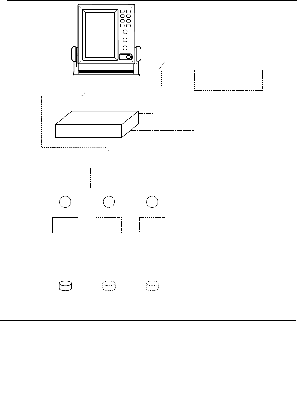
SYSTEM CONFIGURATION
TRANSDUCER
DISTRIBUTION
BOX
FE-702
DISPLAY UNIT
FE-701
JUNCTION BOX
JIS F8821-1
MATCHING BOX MB-502 (for 50B-6B)
MB-504 (for 200B-8B)
JB JB
IEC 61162-1
EIA-232C
IEC 61162-1 Navigation Device
Navigation Device
Personal Computer
IEC 61162-1
JB
TRANSDUCER SWITCH BOX
EX-8
DIGITAL DEPTH INDICATOR
FE-720
CONTACT CLOSURE Alarm Unit
: Standard Supply
Ship’s mains
100-115 VAC/200-230 VAC
or
24 VDC
: Optional Supply
TERMINAL BOX
DS-802
: Local Supply
FE-700 system configuration
PRINCIPLE OF OPERATION
The FE-700 uses ultrasonic pulses to detect the seabed and other underwater objects. The display unit
contains all basic electric circuits and logic processor. Electrical pulses are converted into acoustical
energy in the transducer fitted on the ship’s hull. The processor measures the time of pulses travelling
between the seabed and transducer and displays the water depths in the graphical form or other forms.
The transducers have a specific beam width with respect to their working frequency, 50 kHz or 200 kHz.
The high frequency has a narrow beamwidth and is immune to aeration when the ship is going astern or in
rough weather. The low frequency has a wide beamwidth and more powerful sounding capability.
SP - 1 E2366S01Q
SPECIFICATIONS OF NAVIGATIONAL ECHO SOUNDER
FE-700
1 DISPLAY UNIT
1.1 Graphical Display 6.5-inch color TFT LCD, 320 x 234 pixels
1.2 Echo Colors 8 colors or 8 level monochrome
1.3 Display Area 133 x 97 mm
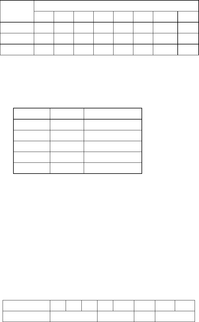
1.4 Basic Display Range
Range
Unit 1 2 3 4 5 6 7 8
Meters 5 10 20 40 100 200 400 800
Feet 15 30 60 120 300 600 1500 2500
Fathoms 3 5 10 20 50 100 200 400
*Default settings; it could be customized for use w/o range 3 and 6.
1.5 Accuracy ±2.5% on any range
1.6 Minimum Range 0.5 m (200 kHz), 2.0 m (50 kHz)
1.7 Draft -10 to 30 m in 0.1 m steps, default 0 m
1.8 Pulse Repetition Rate (PRR)
Depth (m) P/L (ms) PRR (pulse/min)
5, 10, 20 0.25 750
40 0.38 375
100 1.00 150
200 2.00 75
400,800 3.60 42
1.9 Display Mode “NAV”: Basic echo presentation with the depth below transducer
“DBS”: Echo presentation with the depth below sea surface (or keel)
“HISTRY”: Historical Echo presentation with the depth
“LOGBOOK”: Echo presentation with the pop-up table showing
Time, Depth and L/L* data memorized at preset interval
“OS DATA”: Echo presentation with the pop-up table of present
navigational data; L/L*, course*, speed*, time, depth
“HELP”: Echo presentation with the help menu and note
“MENU”: Echo presentation with the user menu
1.10 Picture Advance Speed
Slow mode 15 minutes or more
Fast mode Picture advance range
Range (m) 5 10 20 40 100 200 400 800
Interval (min.) 1.8 8 20 30
SP - 2 E2366S01Q
1.11 User Setting Gain, Range, Alarm, Draft, Brilliance, Dimmer, Color, Auto
1.12 Auto Set Mode Gain, range and clutter will be automatically adjusted.
1.13 Alarm Shallow water (default 20 m), Bottom lost, Power drop
1.14 Logbook Display Depth, Internal clock, L/L*
1 hour at 5 sec Interval, 12 hours at 1 minute interval and 24
hours at 2 minutes interval
*: External navigational sensor required.
2 TRANSCEIVER CHARACTERISTICS (BUILT IN DISPLAY UNIT)
2.1 Transmit Frequency 50 kHz or 200 kHz
2.2 Output Power 600 Wrms
3 DIGITAL DEPTH INDICATOR
3.1 Display 4.5-inch monochrome LCD
3.2 Depth Indication **.* m (less than 100m)
**** m (100 m or more)
3.3 Power supply 24 VDC, 150mA
3.4 Coating color Panel: N3.0, Chassis: 2.5GY5/1.5
3.5 Waterproofing IPX5
4 TRANSDUCER TYPE AND BEAMWIDTH
4.1 50B-6B (50 kHz): 35°
4.2 200B-8B (200 kHz): 6°
5 INTERFACE
5.1 Serial Input Data IEC61162-1, current loop; 1 port
RMA: L/L, ground track speed, Track
RMC: L/L(GPS), ground track speed, Track, Time
GLL: L/L
GGA: L/L
VTG: Ground track speed,
Track (True/Magnetic selected on menu)
ZDA: Time
5.2 Serial Output Data IEC61162-1, output period: 1 sec.; 3 outputs/
1 port
SDDPT: Depth (m), Draft (m)
SDDBT: Depth (ft, m, fa) below transducer
SDDBS: Depth (ft, m, fa) below sea surface
5.3 Serial I/O Data RS-232C, 1 port
Output Depth, clock, L/L, ship’s speed, course
SP - 3 E2366S01Q
Input Control command for PC
5.4 Alarm (Depth, Power) Contact closure signal, normal open or normal close,
250 VAC/ 200 VDC, 3A max.
6 POWER SUPPLY
24 VDC (-10%, +30%): 20W or
100-115/200-230 VAC, 1 phase, 50/60Hz: 20VA.
7 ENVIRONMENTAL CONDITION
7.1 Temperature -15 °C to +55 °C
7.2 Relative Humidity 93% or less at 40 °C
7.3 Waterproofing Display Unit: IEC IPX5
Distribution Box: IEC IPX2
Matching Box: IEC IPX2
7.4 EMC Emission IEC 60945 Ver.3
7.5 Category of Equipment Units
Display Unit protected from the weather
Distribution Box protected from the weather
Matching Box protected from the weather
Transducer Submerged area
8 COATING COLOR
8.1 Display Unit Panel: N3.0, Chassis: 2.5GY5/1.5
8.2 Distribution Box/ Matching Box
2.5GY5/1.5
1
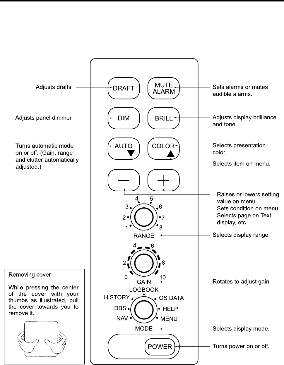
1 OPERATION
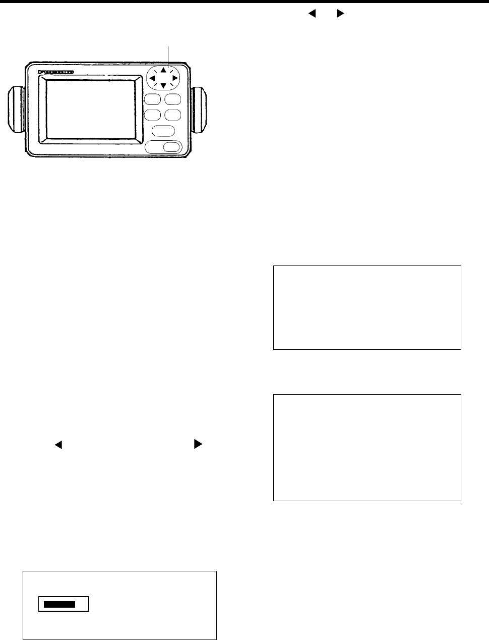
1.1 Control Description
All operation of the FE-700 is carried out with the controls on the front panel of the display unit. Rotary
controls respond immediately to your command but some touch keys require the successive operation.
•
•
•
2
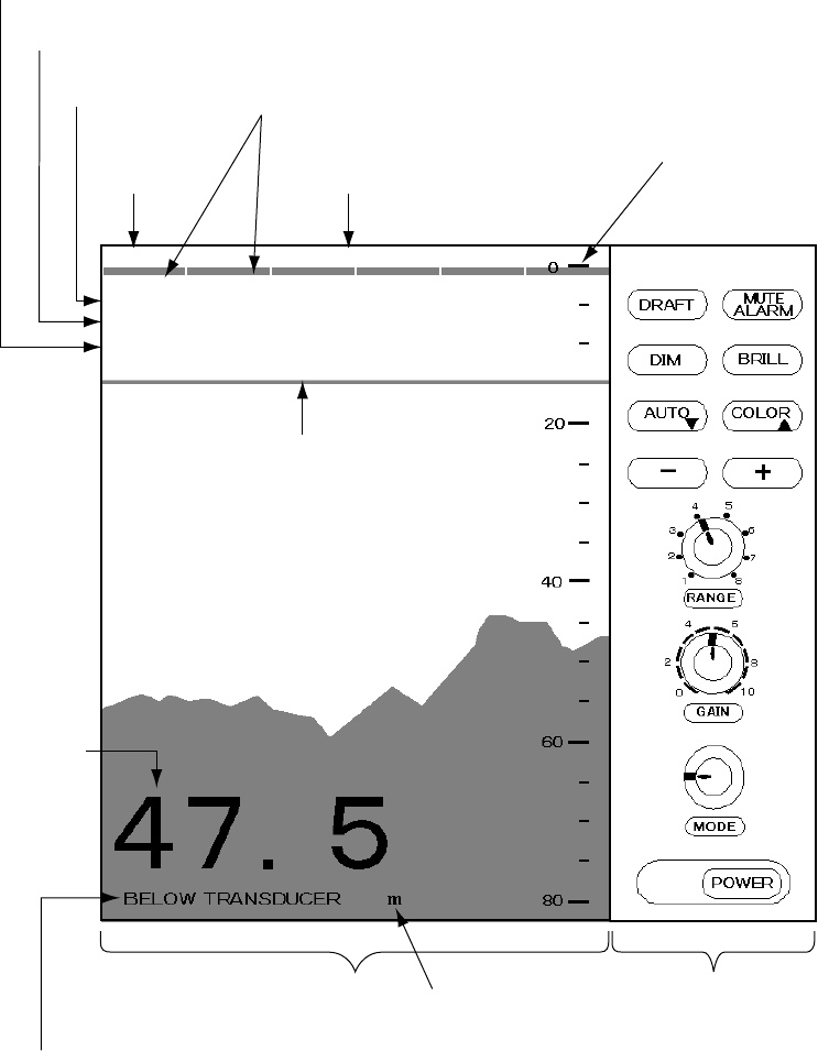
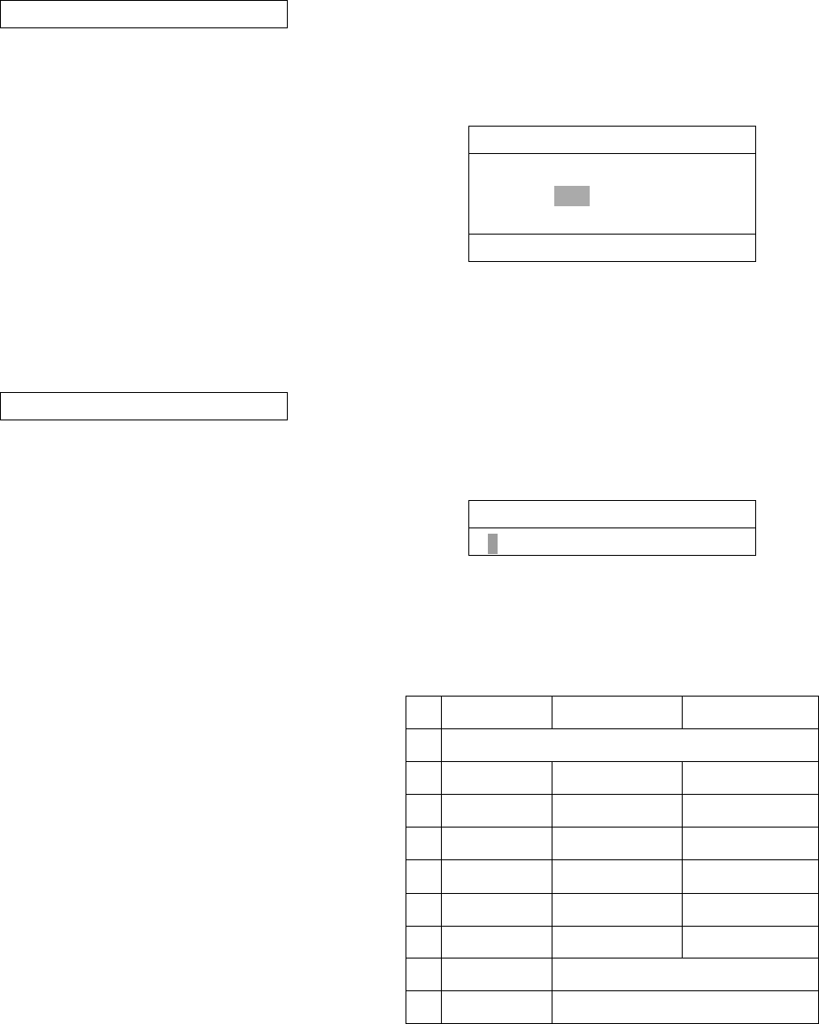
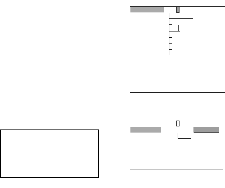
1.2 Indications, Markers
Auto
mode
Range setting
Gain setting
Display mode
Depth alarm line
Depth
Explanation of depth
(Below transducer, or
below surface)
Alarm
setting Range scale
Control panel
Screen
ALARM 15m
AUTO
RANGE: 4
GAIN: 5.5
MODE: NAV
Depth unit
NAV
DBS
LOGBOOK
OS DATA
HELP
MENU
HISTORY
FORE 50kHz
Transducer in use ( when using
transducer switch box. )

3
1.3 Turning On/Off
1. Turning on: Press the POWER Switch.
Self-test starts, showing the condition of the
logic circuits. The program number is
displayed.
ROM: OK
DRAM: OK
SRAM: OK
BATTERY: OK
PROGRAM NO. 0252297002
2. Select a mode with the MODE Selector. The
NAV position of the selector is recommended
for general use. Display color is amber by
default but may be customized. The unit of
measurement is meters. You can freely
select another mode at any time.
3. Turning off: Press the POWER Switch
again.
Wait at least 5 s before reapplying the power.
Note: When two transducers are installed, make
sure which transducer is used.
Note: When lat/long data input error occurs,
“EPFS” ERROR appears on the screen.
(EPFS: Electronic Position-Fixing System
such as GPS receiver)
1.4 Tone and Brilliance
1. Press the BRILL key. The tone and brilliance
setting window appears.
LOW ▼ ▲ HIGH
BRILL: 8
LOW
-
+ HIGH
TONE: 3
2. Press the [+] or [
-
] key for desired tone (in
reality, Contrast).
3. Press the [▲] or [▼] key for desired
brilliance. Pressing the BRILL key also
changes the brilliance from minimum to
maximum and vice-versa.
Note: Tone or brilliance must be adjusted within
10 seconds after pressing the BRILL key.
Otherwise the tone and brilliance window
will be erased.
1.5 Panel Dimmer
1. Press the DIM key. The panel dimmer setting
window appears.
LOW
-
+ HIGH
DIMMER: 5
2. Press the [+] or [
-
] key for desired
illumination of the control panel. Pressing
DIM key also changes the illumination level.
4
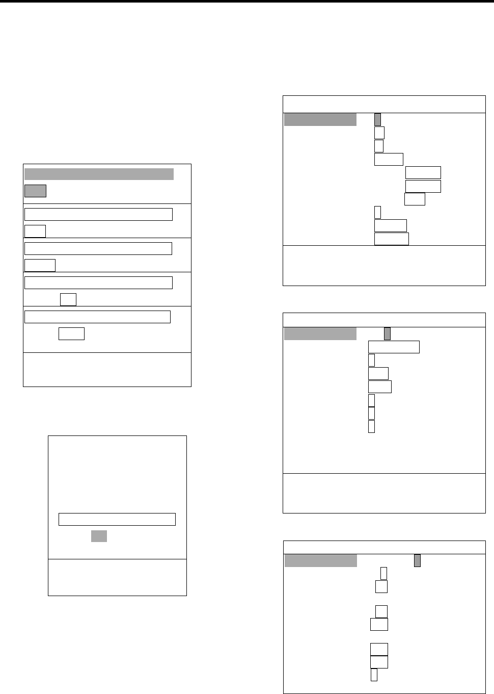
1.6 Display Mode
The Mode Selector choose the display mode
among NAV, DBS (depth below surface),
HISTORY, LOGBOOK, OS DATA, HELP, and
MENU.
1.6.1 NAV mode
The depth from the transducer to the seabed
(bottom clearance) is shown on the screen. Note
“BELOW TRANSDUCER” appears at the bottom
of the screen in this mode.
Default is,
Color: Amber
Range: Automatic range switching
Window: 15 minutes
Shallow depth alarm: 20 m
NOTE: These parameters can be customized to
your preference and the last setting is used at a
next switch-on. This is true on all other modes.
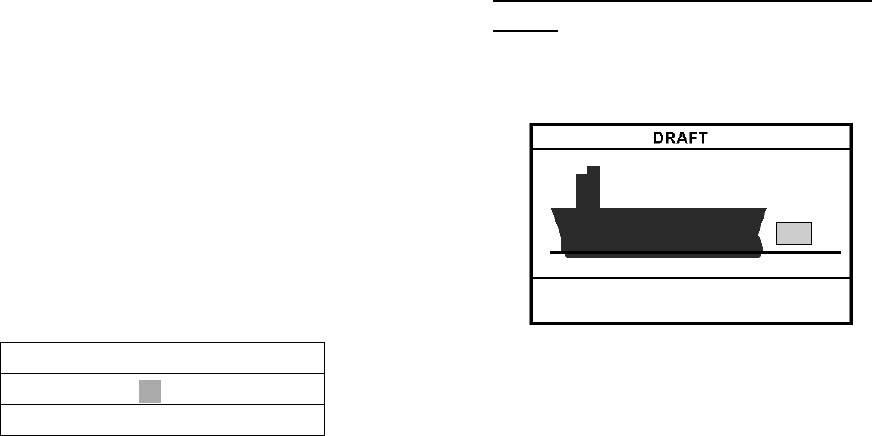
1.6.2 DBS mode
The Depth Below Surface mode provides a
draft-adjusted depth reading and will be useful in
referencing to the nautical chart. The draft should
be adjusted by the DRAFT key according to the
actual draft value. If you find any difficulty to
check for the draft value, use the NAV mode.
When the DBS mode is selected, the message
“Confirm and set ship’s draft to use DBS mode”
appears. Confirm ship's draft and set it by
referring to section 1.12.
BELOW KEEL (when the draft setting is –10.0 to
–0.1) or BELOW SURFACE (when the draft
setting is 0 to 30.0) appears at the bottom of the
display and the draft value appears at the upper
right-hand corner in the DBS mode.
CAUTION
DBS is not a water clearance below
keel.
Do not use this mode in shallow
waters to avoid grounding.
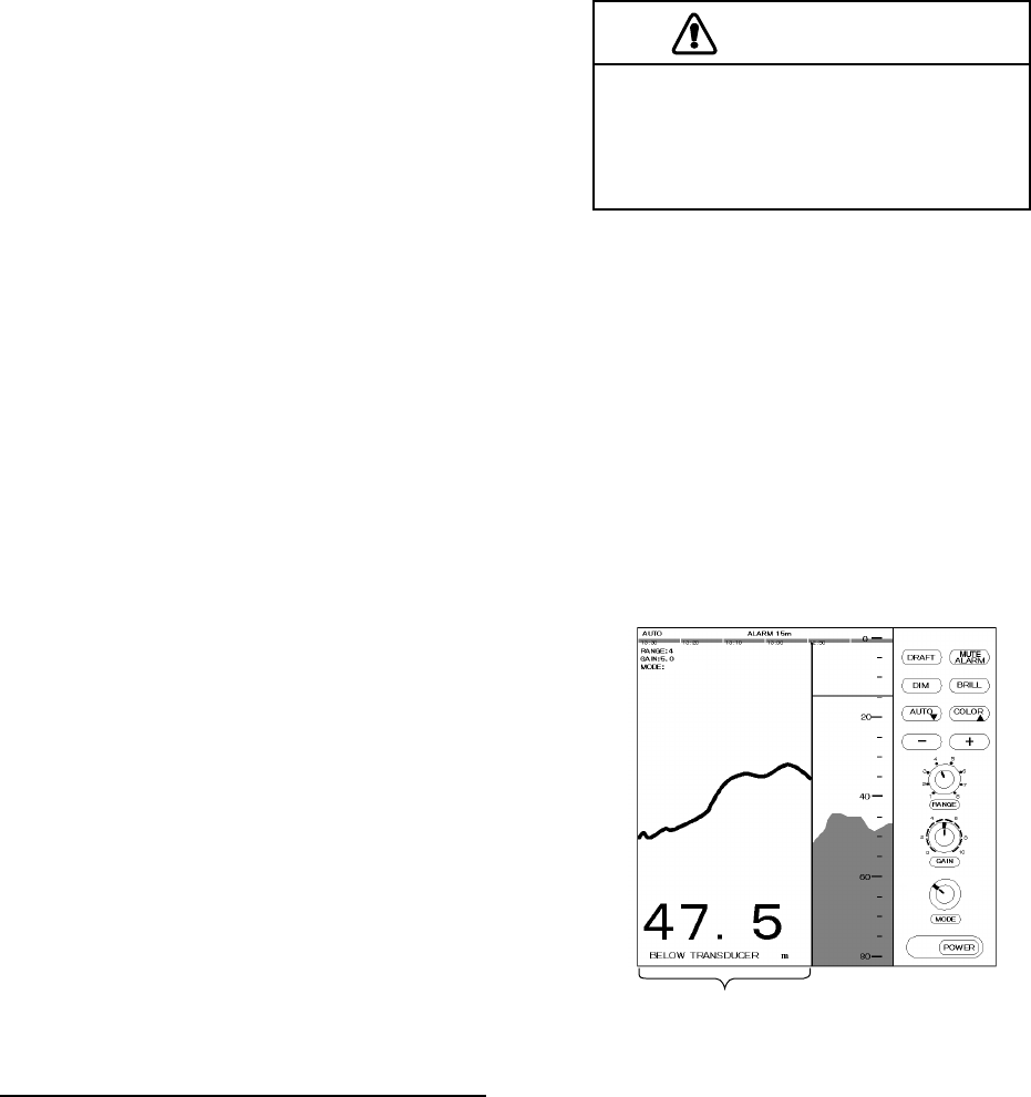
1.6.3 HISTORY mode
This mode provides a mix of Contour and Strata
displays. The Contour display can be scrolled
over the past 24 h while the right side Strata
display (layers of different colors according to
reverberation strengths) shows the latest
sounding for 5 minutes.
Pressing the [+] or [
-
] key moves the Contour
display forwards or backwards, respectively.
History of the bottom
MENU
HELP
OS DATA
LOGBOOK
HISTORY
DBS
NAV
HISTORY
If the range scale for both the Contour and Strata
display must be the same. If they are not, the
message “OUT OF RANGE” appears.
The update of the contour data may take max.
one minute. Wait for one minute to display
accurate contour if you change the range scale.
5
1.6.4 LOGBOOK mode
The LOGBOOK shows time, depth and own ship
position in tabular form in a pop-up window. The
logging is selected with the INTERVAL option on
the menu among 5 s, 1 min and 2 min. (See
section 2.6.)
There are 60 pages and the total memory
capacity is 720 points. Page 60/60 is the latest
data and 1/60 is the oldest data. Pressing [
-
] or
[+] key changes the pages.
60/60
TIME DEPTH L/L
11:00:00 47.5
36°55.012’N
135°23.123’E
11:01:00 47.5 36°55.012’N
135°23.123’E
11:02:00 47.5 36°55.013’N
135°23.123’E
11:03:00 47.5 36°55.013’N
135°23.123’E
11:04:00 47.5 36°55.014’N
135°23.123’E
11:05:00 47.5 36°55.014’N
135°23.123’E
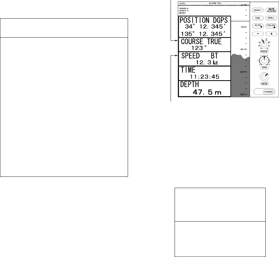
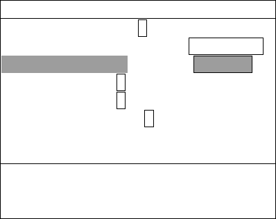
1.6.5 OS DATA mode
This display mode indicates own ship position,
GPS-derived course and speed, and time and
depth in digital form. You can read the data of
your particular interest in large characters. The
screen continues to display the sounding data in
the background. Part of graphical indication is
visible to the right of data slips.
BT means Bottom track
TRUE(true course) or
MAG (magnetic course) appears.
OS DATA
NAV
DBS
LOGBOOK
OS DATA
HELP
MENU
HISTORY
N
E
There are two kinds of OS DATA displays: DATA
1 and DATA 2, as selected on the system menu.
DATA 1 is the default setting, and it is shown in
the figure above.
The DATA 2 display is as below.
TIME UTC
11:23:45
DEPTH
172 m
Note: When lat/long data input error occurs in
the DATA 1 mode, “EPFS” ERROR
appears on the screen. (EPFS: Electronic
Position-Fixing System such as GPS
receiver)

6
Enlarging data of interest
You can enlarge one of the data indications as
follows:
1. Press the [▲] or [▼] key to select the data
you want to enlarge. Current section is
circumscribed with the blue cursor. For
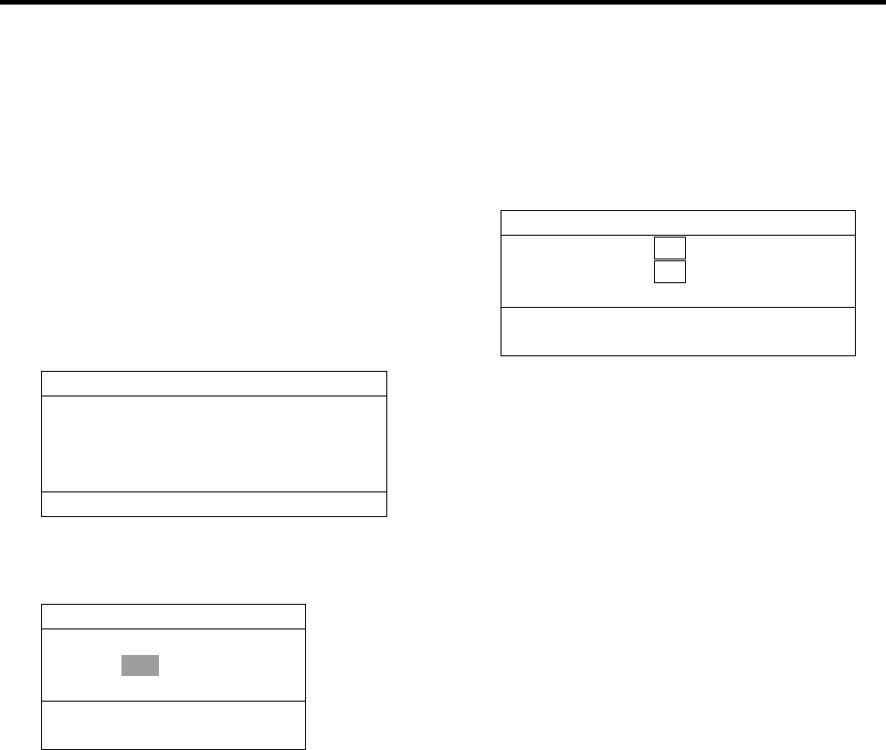
example, select the depth cell.
2. Press the [+] key.
DEPTH
172 m
3. To return to the original display, press the [
-
]
key.
1.6.6 HELP display
This mode provides information about keys.
Press desired key to obtain the corresponding
information. The example below shows help
information for MUTE ALARM.
HELP MENU
DRAFT MUTE
ALARM
DIM BRILL
AUTO COLOR
-
+
PRESS KEY.
MUTE ALARM
To set or
acknowledge alarms:
1. Press MUTE ALARM key.
2. Press [
-
] or [+]
key to set alarm
depth.
3. Press MUTE ALARM
key to silence
the alarm.
PRESS KEY.
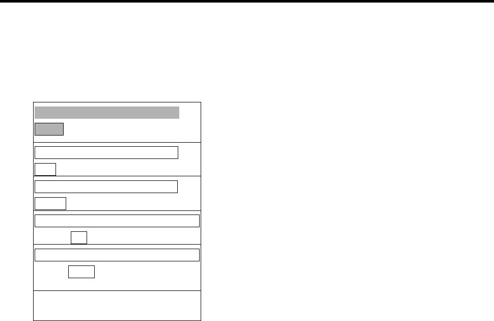
1.6.7 MENU display
The menu provides functions which normally do
not require frequent adjustment. For details see
Chapter 2.
CLUTTER
9 (0∼16)
INTERFERENCE REJECT
OFF IR1 IR2 IR3
PICTURE ADVANCE
SLOW FAST
TREND INDICATOR
OFF ON
INTERVAL
5 s 1 min 2 min
1/2
▼▲: To select item
-
+: To set option
Press the [▼] key, and the following appears.
CAUTION!
SYSTEM MENU IS ONLY
FOR INSTALLATION. DO
NOT CHANGE SETTINGS.
GO TO SYSTEM MENU?
NO YES
2/2
▲: To select item
-
+: To set option
7
1.7 Range Scale
If the depth goes out of the correct display area,
increase or decrease the range until the seabed
appears near the center of the screen.
Adjust the Range Control, and current range
selection is shown in the range display window.
RANGE 5 m
In the AUTO mode, the range scale is
automatically adjusted. See section 1.9 for
details.
1.8 Gain Control
The GAIN Control adjusts the sensitivity of the
receiver. The AUTO mode provides automatic
adjustment and you are normally not required to
adjust it. Current setting is shown at the upper
left-hand corner. Adjust the GAIN Control and the
following window appears.
GAIN 5.5
Adjust the GAIN Control so that a slight amount
of noise remains on the screen. Generally, use a
higher gain setting for greater depths and a lower
setting for shallower waters. Adjusting range is
between 0.0 and 10.0 in 0.5 steps.
1.9 Automatic Operation
The automatic function automatically selects the
proper gain, range scale and clutter level
according to depth. It works as follows:
• The range changes automatically to locate the
bottom on the lower half of the screen. It jumps
to one step shallower range when bottom
echoes reach a halfway point of the full scale
from top and to one step deeper range when
they come to the lower edge of the scale.
• The gain is automatically adjusted to display
the seabed in specified color.
• Clutter level (on the menu), which works as a
threshold control to suppress overall noise, is
automatically adjusted.
Note: The AUTO MODE is cancelled whenever
the range or the gain is changed.
How to enable/disable automatic
operation
1. Press the AUTO key. The AUTO mode
window appears.
AUTO MODE
OFF ON
-
/ +: To set option
2. Press the [+] key to select ON or the [
-
] key
to select OFF.
1.10 Picture Colors
1. Press the COLOR key. The following window
appears.
COLOR
- 1 2 3 4 5 6 7 8 9 +
2. Press the [+] or [
-
] key to select a number,
referring to the table below. (You can see the
result of your selection on the display.)
Background Seabed Others marks
1 Monochrome, 8 intensities
2 Blue Red infill 6 colors
3 Black Red infill 6 colors
4 White Red infill 6 colors
5 Blue Yellow infill 6 colors
6 Black Yellow infill 6 colors
7 White Yellow infill 6 colors
8 Black 7 colors (Strata)
9 White 7 colors (Strata)
8
Monochrome (amber) is the default setting. The
Strata display contains multiple colors depending
on the reflectivity from underwater objects of the
sounding pulses. Red is strongest, followed by
brown, orange, yellow, blue, and light blue.
1.11 Shallow Depth Alarm
The shallow depth alarm sounds when the
seabed is shallower than the preset depth. The
default in the NAV position is 20 m. You can
adjust the alarm depth as below:
Activating/deactivating the alarm
1. Press the MUTE ALARM key to display the
depth alarm setting window.
DEPTH ALARM
10 m
-
/ +: To set option
2. Press the [+] or [
-
] key to change setting
depth. The setting is shown digitally at the
top of the screen and graphically key the
depth alarm line.
When the alarm is activated, the message
“SHALLOW DEPTH ALARM” is displayed at the
center on the screen.
Note: When the draft setting is –10.0 to –0.1
in the DBS mode, the shallow depth alarm setting
will show a minus value. At this time, the alarm
setting value indication shows “****” and the
alarm function is disabled.
Acknowledging the alarm
You can silence the alarm by pressing the MUTE
ALARM key. The message “SHALLOW DEPTH
ALARM” moves to upper side of the screen.
1.12 Draft
It is necessary to set the draft to use the DBS
display mode, which shows depth below surface.
1. Select DBS with the MODE control.
“Confirm and set ships draft to use DBS
mode.” appears.
2. Press the DRAFT key to display the draft
setting window.
0.0 m
-/+: To set option
3. Press the [+] key to increase the setting
depth and [
-
] key to decrease it. The setting
depth is -10 to 30 m in steps of 0.1 m.
The above window disappears in 10 seconds.
The draft setting is displayed at the upper right
corner and the range scale is shifted according to
the draft setting.
9
2 MENU OPERATION
2.1 Menu Overview
The menu has several functions for advanced
operation.
1. Select MENU with the MODE Selector.
CLUTTER
AUTO (0∼16)
INTERFERENCE REJECT
OFF IR1 IR2 IR3
PICTURE ADVANCE
SLOW FAST
TREND INDICATOR
OFF ON
INTERVAL
5 s 1 min 2 min
1/2
▼▲: To select item
-
+: To set option
2. Press the [▲] or [▼] key to select menu
item. As you operate the [▲] or [▼] key, the
selected item and its current setting appear
in reverse video.
3. Press the [
-
] or [+] key to select option
desired.
4. Set the MODE Selector in another position
to close the menu.
2.2 Suppressing Low Level
Noise
Light-blue dots may appear overall screen. This
is mainly due to dirty water or noise. This noise
can be suppressed by adjusting CLUTTER (in
reality, Threshold of the amplifier).
When the automatic mode is on, the
suppression setting is automatically adjusted.
For manual override, do the following:
1. Select MENU with the MODE Selector.
2. Select CLUTTER by pressing the [▲] key.
3. Press the [
-
] or [+] key to select clutter
rejection level desired. The higher the
number the higher the degree of
suppression. Note that weak echoes may
not be displayed when the clutter circuit is
on.
2.3 Suppressing Interference
Interference from other acoustic equipment
operating nearby or other electronic equipment
on your boat may show itself on the display.
To suppress interference, do the following:
1. Select MENU with the MODE Selector.
2. Select INTERFERENCE REJECT by
pressing the [▲] or [▼] key.
3. Press the [
-
] or [+] key to select degree of
suppression desired; OFF, IR1, IR2 or IR3.
The higher the number the greater the
degree of suppression.
Note that oversuppression will weaken the
sensitivity.

10
2.4 Picture Advance
The picture advance speed determines how
quickly the vertical scan lines run across the
screen.
1. Select MENU with the MODE Selector.
2. Select PICTURE ADVANCE by pressing the
[▲] or [▼] key.
3. Press the [+] or [
-
] key to select speed
FAST or SLOW, respectively. The advance
speed varies with the range scale and the
viewing length of 15-16 minutes is available
on all ranges (IMO requirements).
Range (m) Display window (minute)
5, 10, 20 1.8/15 (FAST/SLOW)
40,100 8/15
200 15/20
400, 800 15/30
2.5 Trend
The future trend of the seabed depths can be
predicted over a specified period of time (See
page 13). The trend index is set with the item
TREND and appears at the top left corner. The
default setting is ON.
θ is inclination angle of bottom.
−2°≤θ≤2° 2°<θ≤10° 10°<θ≤45° 45°<θ≤90°
−2°>θ≥−10° −10°>θ≥−45° −45°>θ≥−90°
2.6 Interval
The interval for sampling data for the
LOGBOOK and HISTORY modes can be set
with INTERVAL, among 5 s, 1 min and 2 min.
The default setting is 1 min.
3/60
TIME DEPTH L/L
11:00:00 47.5 36°55.012’N
135°23.123’E
11:01:00 47.5 36°55.012’N
135°23.123’E
11:02:00 47.5 36°55.013’N
135°23.123’E
11:03:00 47.5 36°55.013’N
135°23.123’E
11:04:00 47.5 36°55.014’N
135°23.123’E
11:05:00 47.5 36°55.014’N
135°23.123’E
In this example, the setting of INTERVAL is
1 minute. That is, the depth and lat/long data are
displayed at 1 minute intervals.
11
3 SYSTEM MENU
3.1 System Menu
The system menu should be set just after
installation and is not always necessary to be
adjusted. If you change any items of the system
menu or even if you open the system menu, the
sounding picture will be cleared. There are three
menus: 1,2,and 3.
1. Select MENU with the MODE Selector.
CLUTTER
9 (0∼16)
INTERFERENCE REJECT
OFF IR1 IR2 IR3
PICTURE ADVANCE
SLOW FAST
TREND
OFF ON
INTERVAL
5 s 1 min 2 min
1/2
▼▲: To select item
-
+: To set option
2. Press the [▼] key several times to display
following window.
CAUTION!
SYSTEM MENU IS ONLY
FOR INSTALLATION. DO
NOT CHANGE SETTINGS.
GO TO SYSTEM MENU?
NO YES
2/2
▲ : To select item
-
+: To set option
3. Select YES by pressing the [+] key.
Confirmation message “ARE YOU SURE?”
appears.
4. Press the [+] key again.
The system menu 1 appears.
5. With the cursor selecting MENU SELECT,
operate the [
-
] or [+] key to select system
menu desired; 1, 2 or 3.
SYSTEM MENU 1
MENU SELECT 1 2 3
DEPTH UNIT m ft fa
SPEED UNIT kt MPH km/h
COURSE TRUE MAG
BOTTOM LOST OFF ALARM
GPS ALARM OFF ALARM
INTERFACE 1:95 1:98 NMEA
ALARM SOUND 1 2 3
OS DATA DATA1 DATA2
LANGUAGE English
▼▲: To select item
-
+: To set option
Select other mode to exit.
↓ Press [+] at menu 1.
↑ Press [
-
] at menu 2.
SYSTEM MENU 2
MENU SELECT 1 2 3
TIME ADJUST INTERNAL EXTERNAL
DAY 1
MONTH JAN
YEAR 2001 (∼2100)
HOUR 0 (0∼23)
MINUTE 0 (0∼59)
SECOND 0 (0∼59)
01 JAN 2001 00:00:00
▼▲: To select item
-
+: To set option
Select other mode to exit.
↓ Press [+] at menu 2.
↑ Press [
-
] at menu 3.
SYSTEM MENU 3
MENU SELECT 1 2 3
BASIC RANGE1 5 (2∼800)
RANGE2 10 m
RANGE3 20
RANGE4 40
RANGE5 100
RANGE6 200
RANGE7 400
RANGE8 800
TREND 1 min
12
3.2 System Menu 1
DEPTH UNIT: Selects unit of depth
measurement among meters, feet, or fathoms.
Default setting is meters.
If "ft" or "fa" is selected, the depth unit is shown
in red characters.
SPEED UNIT: Selects unit of speed
measurement among knots, statute miles per
hour, or kilometers per hour. Default setting is
knots. Requires speed data, from external
device.
COURSE: Selects heading reference; true or
magnetic. Default setting is TRUE.
BOTTOM LOST: Turns on or off the bottom loss
warning. “ALARM” sounds the alarm if the
bottom signal is not detected. Default setting is
“ALARM” (alarm is enabled).
GPS ALARM: The audible alarm may be
released when the position-fixing mode is
switched from DGPS to GPS and vice versa.
Default setting is “ALARM” (alarm is enabled).
Choose “OFF” if you do not need to be alerted
with the audible alarm when the position-fixing
mode is switched.
INTERFACE: Selects I/O signal format between
the FE-700 and external equipment; IEC format
“1:95” (1995 version) or “1:98” (1998 version), or
NMEA format. Default setting is IEC “1:98”.
When selecting the “1:98”, DPT has max. range
in use (See page 24).
Output Input
IEC 61162-1 DPT
RMA, RMC
GLL, VTG
ZDA, GGA
NMEA 0183 DBT (Ver.1.5)
DBS (Ver.1.5)
DPT (Ver.2.0)
RMA, RMC
GLL, VTG
ZDA, GGA
ALARM SOUND: Selects audio alarm sound
among 1, 2 or 3. Default setting is 1.
1: Continuous sound
2: Intermittent sound; 0.5 s on and 0.5 s off.
3: Intermittent sound; 1 s on and 1 s off.
OS DATA: Selects own ship data display mode;
DATA 1 or DATA 2. DATA1 is the default setting.
If a navigation device is not connected to the
FE-700, select DATA 2.
LANGUAGE: Currently English is only available.
3.3 System Menu 2
TIME ADJUST: Selects internal clock or external
clock (UTC clock). Default setting is INTERNAL.
For INTERNAL, set current day, month, year,
hour, minute and second with [+], [
-
], [▼] or [▲]
key. The setting clock appears and it counts
upward.
SYSTEM MENU 2
MENU SELECT 1 2 3
TIME ADJUST INTERNAL EXTERNAL
DAY 1
MONTH JAN
YEAR 2001 (∼2100)
HOUR 0 (0∼23)
MINUTE 0 (0∼59)
SECOND 0 (0∼59)
01 JAN 2001 00:00:00
▼▲: To select item
-
+: To set option
Select other mode to exit.
If EXTERNAL is selected, the screen changes
as follows.
SYSTEM MENU 2
MENU SELECT 1 2 3
TIME ADJUST INTERNAL EXTERNAL
TIME DIFFERENCE AUTO MANUAL
0:22:40
▼▲: To select item
-
+: To set option
Select other mode to exit.
TIME DIFFERENCE: Selects auto (UTC) or
manual. Auto uses the time difference in ZDA
(IEC 61162-1). In manual, it is necessary to
enter the time difference in hours and minutes.
13
SYSTEM MENU 2
MENU SELECT 1 2 3
TIME ADJUST INTERNAL EXTERNAL
TIME DIFFERENCE AUTO MANUAL
TIME DIFF HOUR 0 (0∼13)
TIME DIFF MIN 0 (0∼59)
TIME DIFF SIGN
-
, +
0:22:40
▼▲: To select item
-
+: To set option
Select other mode to exit.
3.4 System Menu 3
RANGE 1- 8: Activates or deactivates specific
range scales. Default ranges are 5, 10, 20, 40,
100, 200, 400, and 800 (meters). Setting area is
2 m to 800 m. The ranges 20 m and 200 m can
not be changed. They are essential in this
equipment.
Note: Ranges must be set in numerical order.
For example, if range 1 is 5 m and range 3 is 20
m, range 2 should be between 6 and 19 m.
Trend: The trend index shows the probable
bottom shape over a specified time within 1-10
minutes. The default setting is 1 minute.
Set the Trend time with [+] or [
-
].
14
4 ECHO QUALITY SETTING
This chapter describes functions useful for
improving echo sounding performance.
4.1 Demonstration Display
The demonstration program shows how the
FE-700 works.
1. Turn off the equipment.
2. Press the POWER Switch while pressing any
key. Release the key when the following
EXTENSION MODE display appears.
EXTENSION MODE
+ : TRANSDUCER SETTING
-
: TEST
▲: CLEAR MEMORY
▼: DEMONSTRATION
SELECT MODE
3. Press the [▼] key to select
DEMONSTRATION.
DEMONSTRATION
OFF ON
-
/+: To set option
▼: EXTENSION MODE
4. Press the [+] key to select ON.
5. Reset the power. "DEMO" appears above
the depth indication on the echo sounder
displays and at the top right-hand corner on
the data and graphic displays.
! To return to the normal operation, select
OFF at step 4 above. Restart the display unit
after waiting 5 s.
4.2 Transducer Setting
After installing the equipment, set the transducer
as follows.
1. Press the [+] key at the EXTENSION MODE
display. The following window appears.
TRANSDUCER SETTING
XDR FORE N/A 50kHz 200kHz
XDR AFT N/A 50kHz 200kHz
▼▲: To select item
-
+: To set option
2. Set as follows by using [▲] or [▼] to select
an item and [+] or[
-
] to set option.
a) If only one transducer is installed, set
XDR FORE field to 50 kHz or 200 kHz,
according to actual installation. Leave the
XDR AFT field as “N/A.”
b) If two transducers are installed via the
switch box EX-8, set XDR FORE field and
XDR AFT field to 50 kHz or 200 kHz,
according to actual installation.
3. Reset the power.
Note: The default settings in the TRANSDUCER
SETTING window are N/A. At the first power-up
after installation, the window appears to set
transducer(s).
15
4.3 Bottom Level
If the depth indication is unstable or the seabed
cannot be displayed steadily notwithstanding the
adjustment of the control panel, you may adjust
the bottom echo level.
CAUTION
If the level is set too low, the FE-700
may not be able to distinguish the
bottom from fish echo and the
depth indication may be unstable
and if set to high the depth
indication does not appear.
1. Press the MUTE ALARM key three times at
the EXTENSION MODE. The start-up screen
appears and shortly thereafter the BOTTOM
LEVEL display appears.
BOTTOM LEVEL
200kHz = 80 (20∼200)
-
+: 200kHz*
*: Either 200 kHz or 50 kHz is displayed
depending on which frequency is used.
2. Set the level with the [+] or [
-
] key. The
default level is 80.
3. Press the POWER switch to finish the
adjustment. Wait about 5 s and then turn on
the power again.
4.4 TVG Level
TVG (Time Varied Gain) compensates for
propagation attenuation of the ultrasonic waves,
reducing surface noise to provide a smooth
display. The TVG lowers receiver sensitivity at
the time of pulse emission and gradually
increases it with time, thereby making objects of
same reflectivity at different depths appear at the
same intensity or colors on the display. The TVG
working depth is down to approximately 150 m
on the 200 kHz system and 350 m on the 50 kHz
system. Outside this range the echoes from the
seabed and fish schools are received in full level.
There is no perceivable deterioration in
performance.
1. Press the DRAFT key three times at the
EXTENSION MODE display. The TVG
SELECT window appears.
TVG SELECT
200kHz = 5 (0∼9)
-
+: 200kHz
2. Set the TVG curve with [+] or [
-
]. The default
level is 5. Attenuation compensation curve is
at 20LogR curve.
3. Press the POWER switch to finish the
adjustment. Wait 5 s, and then turn it on
again.
4.5 Echo Offset
The echo offset feature functions to compensate
for too weak or too strong echo level. If the on-
screen echo level appears to be too weak or too
strong and the level cannot be adjusted
satisfactorily with the GAIN control, do the
following to adjust echo level.
1. Press the DIM key three times at the
EXTENSION MODE display. The ECHO
OFFSET screen appears.
ECHO OFFSET
200kHz: 0 (
-
99∼+99)
-
+: 200kHz
2. Set the offset with [+] or [
-
]. The default
value is 0.
3. Press the POWER switch to finish the
adjustment. Wait about 5 s and then turn it
on again.
16
5 OPERATION OF DIGITAL DEPTH
INDICATOR FE-720 (OPTION)
MENU ENT
DISP DIM
PWR
*
Omnipad
The Digital Depth Indicator FE-720 is an optional
remote display. The panel illumination can be
locally adjusted on the control panel or on the
optional hand dimmer box.
5.1 Basic Operation
5.1.1 Turning on
Press the POWER key. The unit beeps and starts
up with the last-used display. To turn off the unit,
press the POWER key again.
5.1.2 Adjusting panel dimmer
1. Press the DIM key.
2. Press [ ] to increase the dimmer or [ ] to
decrease it. The default is level 4.
3. Press the ENT key to finish the adjustment.
5.1.3 Adjusting Contrast
1. Press the [∗] key. The following window
appears.
CONTRAST (0-63)
48
EXIT: [ENT]
2. Press [ ] or [ ] until the required value is
reached. The range of adjustment is from
0 (Min.) to 63 (Max.). The default is 48.
3. Press the ENT key to set.
Note: The contrast is automatically set to the
default when you turn on the power.
5.1.4 DEPTH MODE
Depths are read either below transducer (keel) or
below seaface irrespective of the main display.
Select the mode as below:
1. Press the DISP key to select the wanted
mode. The mode changes as below with
each press.
DEPTH FORE 50kHz
123 m
BELOW TRANSDUCER
Depth below transducer
DEPTH FORE 50kHz
128 m
BELOW SURFACE*
DRAFT: 5.0 m
Depth below surface. Draft is
determined on the main Display Unit
FE-701.
*: If the draft setting is –10.0 to -0.1 (refer to
page 8.) BELOW KEEL is displayed
instead of the BELOW SURFACE.
17
5.2 Menu Operation
5.2.1 Dimmer control
The dimmer is controlled either with the DIM key,
or the optional Dimmer Controller. The method of
control must be selected on the menu.
1. Press the MENU key to display the main
menu.
MENU
DIM CONTROL
PANEL ONLY
/LANG. ENGLISH
UNITS m
ALARM SET ON
TEST
2. Press [▲] or [▼] to select DIM CONTROL.
3. Press the ENT key. The following window
appears.
MENU
DIM CONTROL
PANEL ONLY
/LANG. PANEL ONLY
UNITS EXT CONTROLLER
ALARM SET EXT DISP
TEST
4. Press [▲] or [▼] to select option desired.
PANEL ONLY: The illumination of the control
panel is adjusted with the DIM key.
EXT CONTROLLER: Illumination of control
panel is adjusted with the optional dimmer
controller (hand dimmer box). The DIM key is
inoperative.
EXT DISP: Not used.
5. Press the ENT key to set.
6. Press the MENU key to finish.
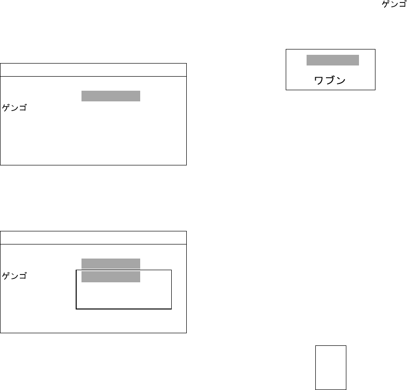
5.2.2 Selecting language
The language in use on the screen is either
English or Japanese.
1. Press the MENU key to display main menu.
2. Press [▲] or [▼] to select the /LANG.
3. Press the ENT key. The following window
appears.
ENGLISH
4. Press [▲] or [▼] to select appropriate option.
The default is English.
5. Press the ENT key to set.
6. Press the MENU key to finish.
5.2.3 Selecting the unit of depth
measurement
The unit of depth measurement is separately
selected from the Main Display FE-701.
1. Press the MENU key to display main menu.
2. Press [▲] or [▼] to select the UNITS.
3. Press the ENT key. The following window
appears.
m
ft
fa
4. Press [▲] or [▼] to select unit.
The default is meter (m).
5. Press the ENT key to set.
6. Press the MENU key to finish.

18
5.2.4 Alarm
You can set turn alarm on or off. In the ON mode,
if the main display unit activates the alarm, the
FE-720 also.
1. Press the MENU key to display main menu.
2. Press [▲] or [▼] to select ALARM.
3. Press the ENT key. The following window
appears.
ON
OFF
4. Press [▲] or [▼] to select appropriate option.
The default is ON.
5. Press the ENT key to set.
6. Press the MENU key to finish.
If the alarm sounds, press any key to silence it.
5.3 Diagnosis
The diagnostic test checks ROM, RAM, keys and
LCD of the FE-720.
1. Press the MENU key to display main menu.
2. Press [▲] or [▼] to select TEST.
3. Press the ENT key. The following window
appears.
TEST START?
(STOP : PWR OFF)
ARE YOU SURE?
YES NO
4. With YES selected, press the ENT key to
start the test. The equipment tests the ROM
and RAM, displaying the results as OK or
NG (No Good). If NG appears, contact your
dealer for advice.
TEST
ROM : OK
RAM : OK
PUSH KEY
(STOP: PWR OFF)
CNT: 001 65-5-0100-003
5. After "PUSH KEY" is displayed, press each
key one by one. The name of the key
pressed momentarily appears if the key is
functioning properly.
The display shows the following message to
inform you that the program is now going to
check the LCD.
<LCD CHECK>
ALL ON 2 SEC
ALL OFF 3 SEC
The whole display brightens for 2 seconds then
turns off for 3 seconds. Test repeats. CNT, which
is number of times the test has been
consecutively executed, is counted up.
6. To stop the test, turn off the power.
5.4 Factory Setting
You can restore default settings to start operation
anew. Press the POWER switch while pressing
[▲]. The message "RESET BACKUP DATA!"
appears. After a while, all default settings are
restored and the depth indication appears.
19
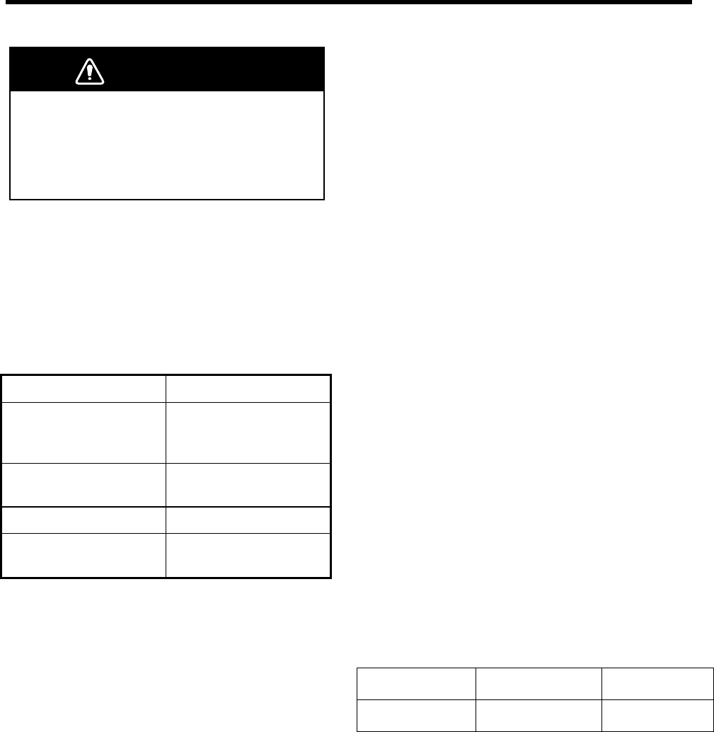
6 MAINTENANCE, TROUBLESHOOTING
Do not open the cover.
There are no user-serviceable parts inside.
Refer any repair work to a qualified
technician.
WARNING
6.1 Checking
Regular maintenance is essential for good
performance. Checking the items listed in the
table below on a regular basis will keep the
equipment in good shape for years to come.
Item Action
Cable run
If conductors are
exposed, replace
cable.
Power cable,
transducer cable plug If loosened, tighten.
Display unit ground If corroded, clean.
Ship's mains voltage If out of rating, correct
problem.
6.2 Cleaning the Display Unit
Dust or dirt on the display unit should be
removed with a soft cloth. If desired a
water-moistened cloth may be used. Do not use
chemical cleaners; they can remove paint and
markings.
6.3 Transducer Maintenance
Marine life on the transducer face will result in a
gradual decrease in sensitivity. Check the
transducer face for cleanliness each time the
ship is dry-docked. Carefully remove any marine
life with a piece of wood or fine-grade sandpaper.
6.4 Replacing the Fuse, Battery
If a fuse blows, find the cause before replacing it.
Use only designated fuses. Using the wrong fuse
will damage the unit and void the warranty.
Three types of fuses are used in the distribution
box FE-702.
For Display Unit : 3 A x 1 pc (24 VDC)
For Digital Depth Indicator: 0.5 A x 2 pcs
For AC input: 1 A x 2 pcs
The Digital Depth Indicator FE-720 uses one fuse
of 1 A, which is inserted in the positive line of
interconnection cable.
A battery installed on a circuit board inside the
display unit preserves data when the power is
turned off. The life of the battery is about three
years. When the battery voltage is low, “battery”
NG appears at the self-test. When this happens,
contact your dealer to request replacement of the
battery.
TYPE Code Number
Lithium Battery CR2450-F2 ST2 000-133-495

20
6.5 Troubleshooting
The table below provides simple troubleshooting procedures which you may follow to restore normal
operation. If you cannot restore normal operation, contact your dealer.
SYMPTOM PROBABLE CAUSES REMEDY
Low power supply Check the supply voltage.
Fuse blown Replace the fuse.
No picture; no reading
measure
Power cable damaged Check the cable and repair.
Transducer cable damaged Repair the cable.
Transducer cable connection
loosened
Tighten the connections.
No echo sounding picture
Transmitter not working Make sure the maximum output power is
selected. (See section 3.2 System Menu 1.)
Low sensitivity Increase the Gain by turning the GAIN control
clockwise.
Low reflectivity from seabed Suspect muddy seabed.
Irregular display
Marine life on transducer Remove marine life from the transducer when
dry docked.
Out of range Check the range scale setting. Loss of seabed display
Air bubbles caused by going
astern or running over other
ship wakes
This is normal, it is not a sign of equipment
trouble.
Wrong installation place of
transducer
Find cause of noise. Relocate the transducer if
noise persists.
Heavy noise
Other echo sounders nearby If more than one echo sounder is working on
the ship, there is no ideal measure to cure the
problem.
Aeration in near surface area Not an equipment problem. Surface noise
Rough weather Not an equipment problem.
21
6.6 Diagnostic Test
The diagnostic test checks the ROM, RAM, color
bar and keyboard for proper operation.
1. Turn on the power while pressing any key.
Release the keys when the following display
appears.
EXTENSION MODE
+ : TRANSDUCER SETTING
-
: TEST
▲: CLEAR MEMORY
▼: DEMONSTRATION
SELECT MODE
2. Press the [
-
] key.
RANGE: 4
GAIN : 150
MODE : 5
BATTERY : OK
PROGRAM No.: 0252297002
Key status
Gain knob setting
Position of Mode knob
Position of Range knob
Color bar
(16 colors)
ROM : OK
DRAM : OK
SRAM : OK
3. The ROM, DRAM, SRAM and internal
battery are checked and the results are
displayed as OK or NG (No Good).
If NG appears, contact your dealer for
advice.
4. Press and release each key (except the
POWER switch) one by one. If the key is
normal, its on-screen location lights in black
while the key is pressed.
5. Operate the controls. The RANGE and
MODE control setting indications should be
the same as actual control settings. The
GAIN control setting indication should be
between 0 and more than 230.
6. Press the POWER SWITCH to finish. Turn
on the power again to resume operation.
6.7 Test Pattern
The test pattern is used to check color
performance.
1. Turn on the POWER SWITCH while pressing
any key.
2. Press the BRILL key three times. Press the
BRILL key again to change the test pattern
as below.
BLACK
↓
WHITE
↓
BLK
RED
GRN
Blue
YEL
PPL
Aqua
WHT
↓
3. Press the BRILL key again to return to the
EXTENSION MODE menu.

22
6.8 Clearing the Memory
All menu settings can be cleared to start afresh.
All default menu settings are restored when the
memory is cleared. For your reference all default
settings are shown in the menu tree at the end of
this manual.
1. Turn on the power while pressing any key.
Release the keys when the EXTENSION
MODE menu appears.
2. Press the [▲] key. The following window
appears.
Restore factory settings.
+: YES
-
: NO
3. Press the [+] key to clear the memory. The
following window appears.
DON’T TURN POWER OFF
UNTIL COMPLETED MEMORY CLEAR
Then the following display appears after the
memory is cleared.
Set data to default.
4. After data is cleared, the EXTENSION
MODE menu appears.
Note: The setting for the items LANGUAGE and
TRANSDUCER in the system menu is not
disturbed when the memory is cleared.
23
7 MENU TREE
MENU CLUTTER (AUTO, 0∼16, 9) Default settings
INTERFERENCE REJECT (OFF, IR1, IR2, IR3) shown in bold.
PICTURE ADVANCE (SLOW, FAST)
TREND INDICATOR (ON, OFF)
INTERVAL (5 s, 1 min, 2 min)
GO TO SYSTEM MENU? (NO, YES)
SYSTEM MENU 1 MENU SELECT (1, 2, 3)
DEPTH UNIT (m, ft, fa)
SPEED UNIT (kt, MPH, km/h)
COURSE (TRUE, MAG)
BOTTOM LOST (OFF, ALARM)
GPS ALARM (OFF, ALARM)
INTERFACE (1:95, 1:98, NMEA)
ALARM SOUND (1, 2, 3)
OS DATA (DATA1, DATA2)
LANGUAGE (English)
SYSTEM MENU 2 MENU SELECT (1, 2, 3)
TIME ADJUST (INTERNAL, EXTERNAL)
DAY
MONTH
YEAR ( ∼2100)
HOUR (0∼23)
MINUTE (0∼59)
SECOND (0∼59)
TIME ADJUST (INTERNAL, EXTERNAL)
TIME DIFFERENCE (AUTO, MANUAL)
TIME DIFF HOUR (0∼13)
TIME DIFF MIN (0∼59)
TIME SIGN (+,
-
)
SYSTEM MENU 3 MENU SELECT (1, 2, 3)
BASIC RANGE1 (5) All basic ranges in meters.
BASIC RANGE2 (10)
BASIC RANGE3 20
BASIC RANGE4 (40)
BASIC RANGE5 (100)
BASIC RANGE6 200
BASIC RANGE7 (400)
BASIC RANGE8 (800)
TREND (1-10 min)
EXTENSION MODE
Any key + [POWER] TRANSDUCER SETTING
TEST
CLEAR MEMORY
DEMONSTRATION
ECHO OFFSET (DIM key x 3 times)
TVG SELECT (DRAFT key x 3 times)
BOTTOM LEVEL (ALARM key x 3 times)
DISPLAY TEST (BRILL key x 3 times)

24
8 DIGITAL INTERFACE
(IEC 61162-1 EDITION 2)
1. I/O Sentences
Input sentences of channel 1 (NAV IN)
RMA, RMC, GLL, GGA, VTG, ZDA
Output sentences of channel 2 (NAV OUT)
DBT, DPT, DBS (NMEA 0183)
Transmission interval
1 s for any sentence
Data transmission
Data is transmitted in serial asynchronous form in accordance with the standard referenced in 2.1 of
IEC 61162-1. The first bit is a start bit and is followed by data bits, least-significant-bit as illustrated
below.
The following parameters are used:
Baud rate: 4800
Data bits: 8 (D7 = 0), parity none
Stop bits: 1
D0 D1 D2 D3 D4 D5 D6 D7
Start
bit
Stop
bit
Data bits
25
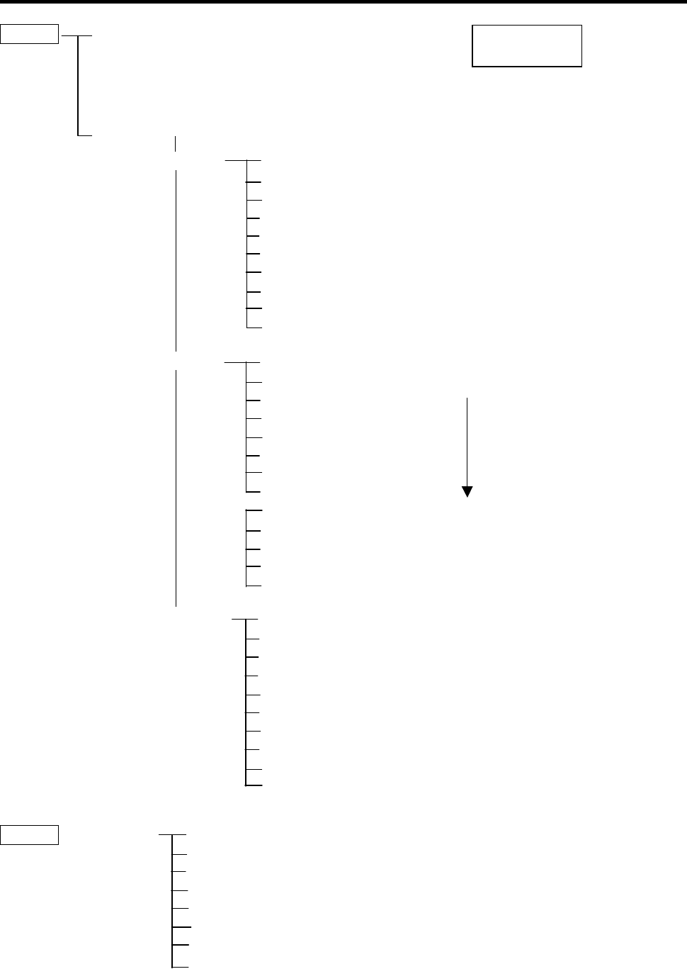
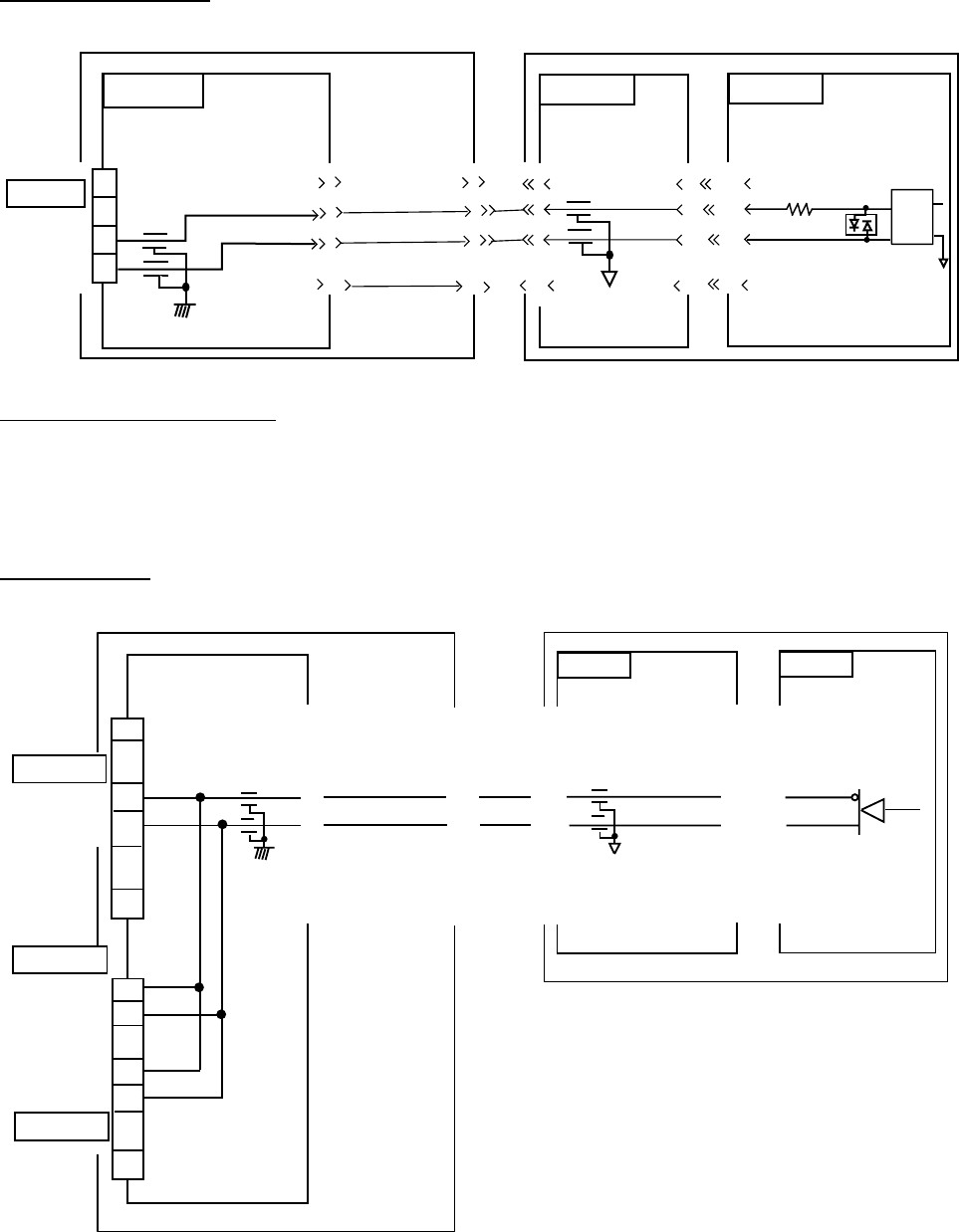
2. Schematic Diagrams
NAV IN port (listener)
NAV IN
RD1_A
RD1_B
1
9
10
02P6283
FE-702
TB1
236-410M1-10
FL5
FL6
1
6
7
10
6
7
10
.
.
..
.
.
1
P1 J1
XHP-10 MJ-A10SRMD
1
6
7
10
1
19
30
02P6281
20
1
19
20
30
02P6280
J3
00-9072-230-101-883
J1
MJ-A10SRMD
CR1
1SS226
R30
560
U9
PC400
4
5
J1
B10B-XH-A
FE-701
FL3
.
.
.
J4
00-900-9072-901-883
1
3
Load requirements as listener
Isolation: Optocoupler
Input Impedance: 560 ohms
Max. Voltage: ±15V
NAV OUT ports
1
7
.
.
.
8
10
.
.
.
NAV OUT 1
TD1_A
TD1_B
1
.
.
.
10
.
.
.
2
6
7
NAV OUT 2
TD1_A
TD1_B
TD1_A
TD1_B
NAV OUT 3
TB1
236-410M1-10
J1
B10B-XH-A
FL3
FL4
>1>
>4>
>5>
>10>
P1
XHP-10
J1
MJ-A10SRMD
>1>>
>4>>
>5>>
>10>>
.
.
.
.
.
.
.
.
.
.
.
.
.
.
.
.
.
.
02P6281
FL3
<<1<
<<4<
<<5<
<<10<
J4
00-9072-230-901-883
J1
MJ-A10SRMD
<1<<1<
<17<<17<
<18<<18<
<30<<30<
U8
14
13
15
02P6280
FE-702 FE-701
J3
00-9072-230-101-883
TB3
236-410
M1-10
.
.
.
.
.
.
.
.
.
.
.
.
Total output for NAV OUT ports: Max. 20 mA
26
3. Sentence Description
DPT - Depth
$--DPT,x.x,x.x,x.x*hh<CR><LF>
| | | |
| | | +----- 4
| | +--------- 3
| +------------ 2
+---------------- 1
1. Water depth relative to trancsducer, in meters
2. Offset from transeducer, in meters(see notes 1 and 2)
3. Maximum range scale in use
4. Checksum
NOTE1 "positive"=distance from transeduser to water-line.
"-"=distance from transducer to keel.
NOTE2 For IEC applications the offset should always be applied
so as to provide depth relative to the keel.
DBS – Depth below surface
$--DBS,x.x,f,x.x,M,x.x,F*hh<CR><LF>
| | | | | | |
| | | | | | +--------- 4
| | | | +--+----------- 3
| | +--+----------------- 2
+--+----------------------- 1
1. Water depth, feet
2. Water depth, m
3. Water depth, fathoms
4. Checksum
DBT – Depth below transducer
$--DBT,x.x,f,x.x,M,x.x,F*hh<CR><LF>
| | | | | | |
| | | | | | +--------- 4
| | | | +--+----------- 3
| | +--+----------------- 2
+--+----------------------- 1
1. Water depth, feet
2. Water depth, m
3. Water depth, fathoms
4. Checksum
27
GLL - Geographic position - latitude/longitude
$--GLL,llll.lll,a,yyyyy.yyy,a,hhmmss.ss,A,a*hh<CR><LF>
| | | | | | | |
| | | | | | | +------- 6
| | | | | | +--------- 5
| | | | | +----------- 4
| | | | +---------------- 3
| | +------+----------------------- 2
+---+----------------------------------- 1
1. Latitude, N/S
2. Longitude, E/W
3. UTC of position
4. Status: A=data valid, V=data invalid
5. Mode indicator(see note)
6. Checksum
NOTE Positioning system Mode indicator:
A = Autonomous
D = Differential
E = Estimated (dead reckoning)
M = Manual input
S = Simulator
N = Data not valid
The Mode indicator field supplements the Status field. The Status field shall be
set to V=invalid for all values of Operating Mode except for A=Autonomous and
D=Differential. The positioning system Mode indicator and Status field shall not
be null fields.
28
GGA - Global positioning system (GPS) fix data
$--GGA,hhmmss.ss,llll.lll,a,yyyyy.yyy,a,x,xx,x.x,x.x,M,x.x,M,x.x,xxxx*hh<CR><LF>
| | | | | | | | | | | | | | |
| | | | | | | | | | | | | | +-- 11
| | | | | | | | | | | | | +---- 10
| | | | | | | | | | | | +--------- 9
| | | | | | | | | | +---+------------ 8
| | | | | | | | +---+------------------ 7
| | | | | | | +------------------------- 6
| | | | | | +---------------------------- 5
| | | | | +------------------------------- 4
| | | +----+--------------------------------- 3
| +---+--------------------------------------------- 2
+------------------------------------------------------------- 1
1. UTC of position
2. Latitude, N/S
3. Longitude, E/W
4. GPS quality indicator (see note)
5. Number of satllite in use,00-12, may be different from the number in view
6. Horizontal dilution of precision
7. Antenna altitude above/below mean sealevel, m
8. Geoidal separation, m
9. Age of differential GPS data
10. Differential reference station ID, 0000-1023
11. Checksum
NOTE
0 = fix not available or invalid
1 = GPS SPS mode, fix valid
2 = differential GPS, SPS mode, fix valid
3 = GPS PPS mode, fix valid
4 = Real Time Kinetic. Satellite system used in RTK mode with fixed integers
5 = Float RTK. Satellite system used in RTK mode with floating fingers
6 = Estimated (dead reckoning) mode
7 = Manual input mode
8 = Simulator mode
The GPS quality indicator shall not be a null field.
29
RMA - Recommended minimum specific LORAN-C data
$--RMA,A,llll.lll,a,yyyyy.yy,a,x.x,x.x,x.x,x.x,x.x,a,a*hh<CR><LF>
| | | | | | | | | | | | |
| | | | | | | | | | | | +------- 10
| | | | | | | | | | | +--------- 9
| | | | | | | | | +---+----------- 8
| | | | | | | | +------------------ 7
| | | | | | | +---------------------- 6
| | | | | | +-------------------------- 5
| | | | | +------------------------------ 4
| | | +----+--------------------------------- 3
| +---+-------------------------------------------- 2
+------------------------------------------------------- 1
1. Status: A=data valid, V=blink, cycle or SNR warning
2. Latitude, degrees N/S
3. Longitude, degrees E/W
4. Time difference A, microseconds
5. Time difference B, microseconds
6. Speed over ground, knots
7. Course over ground, degrees true
8. Magnetic variation(see note 1),degree E/W
9. Mode indicator(see note 2)
10. Checksum
NOTE 1 - Easterly variation(E) subtracts from true course
Westerly variation(W) adds to true course
NOTE 2 Positioning system Mode indicator:
A = Autonomous
D = Differential
E = Estimated (dead reckoning)
M = Manual input
S = Simulator
N = Data not valid
The Mode indicator field supplements the Status field. The Status field
shall be set to V=invalid for all values of Operating Mode except for
A=Autonomous and D=Differential. The positioning system Mode indicator
and Status field shall not be null fields.
30
RMC - Recommended specific GPS/TRANSIT data
$--RMC,hhmmss.ss,A,llll.lll,a,yyyyy.yyy,a,x.x,x.x,xxxxxx,x.x,a,a*hh<CR><LF>
| | | | | | | | | | | | |
| | | | | | | | | | | | +--- 10
| | | | | | | | | | | +----- 9
| | | | | | | | | +--+------- 8
| | | | | | | | +--------------- 7
| | | | | | | +--------------------- 6
| | | | | | +------------------------- 5
| | | | +---+---------------------------- 4
| | +---+---------------------------------------- 3
| +--------------------------------------------------- 2
+---------------------------------------------------------- 1
1. UTC of position fix
2. Status: A=data valid, V=navigation receiver warning
3. Latitude, N/S
4. Longitude, E/W
5. Speed over ground, knots
6. Course over ground, degrees true
7. Date: dd/mm/yy
8. magnetic variation, degrees E/W
9. Mode indicator(see note)
10. Checksum
NOTE Positioning system Mode indicator:
A = Autonomous
D = Differential
E = Estimated (dead reckoning)
M = Manual input
S = Simulator
N = Data not valid
The Mode indicator field supplements the Status field. The Status field
shall be set to V=invalid for all values of Operating Mode except for
A=Autonomous and D=Differential. The positioning system Mode indicator
and Status field shall not be null fields.
31
VTG- Course over ground and ground speed
$--VTG,x.x,T,x.x,M,x.x,N,x.x,K,a*hh<CR><LF>
| | | | | | | | | |
| | | | | | | | | +------- 6
| | | | | | | | +--------- 5
| | | | | | +--+----------- 4
| | | | +--+----------------- 3
| | +--+----------------------- 2
+--+----------------------------- 1
1. Course over ground, degrees true
2. Course over ground, degrees magnetic
3. Speed over ground, knots
4. Speed over ground, km/h
5. Mode indicator(see note)
6. Checksum
NOTE Positioning system Mode indicator:
A = Autonomous
D = Differential
E = Estimated (dead reckoning)
M = Manual input
S = Simulator
N = Data not valid
The positioning system Mode indicator field shall not be a null field.
ZDA - Time and date
$--ZDA,hhmmss.ss,xx,xx,xxxx,xx,xx*hh<CR><LF>
| | | | | | |
| | | | | | +--------- 7
| | | | | +----------- 6
| | | | +-------------- 5
| | | +------------------ 4
| | +---------------------- 3
| +------------------------- 2
+--------------------------------- 1
1. UTC
2. Day, 01 to 31(UTC)
3. Month, 01 to 12(UTC)
4. Year(UTC)
5. Local zone hours, 00h to +-13h
6. Local zone minutes, 00 to +59
as local hours
7. Checksum
32
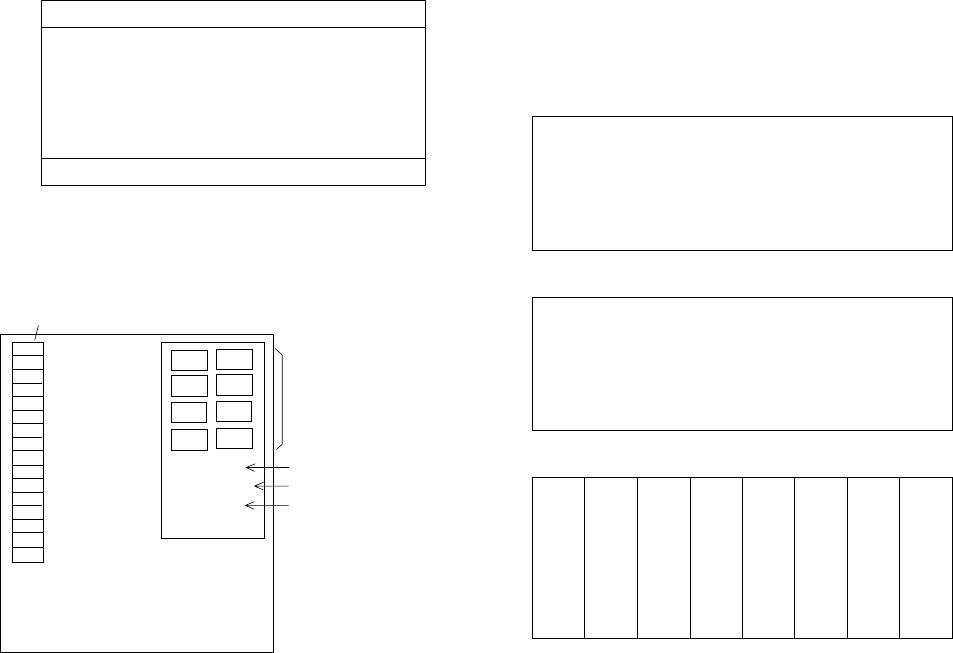
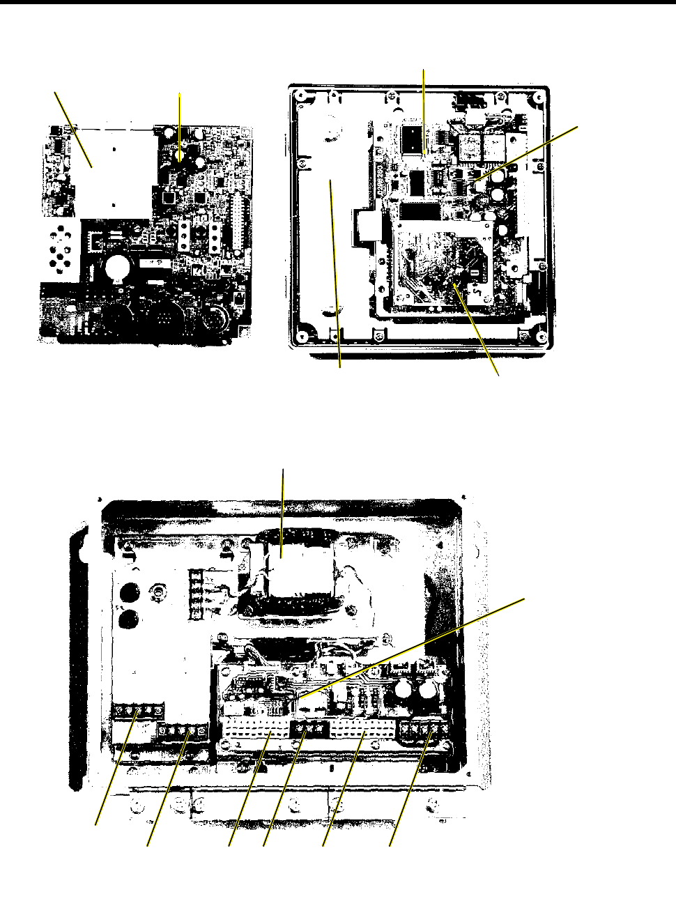
9 PARTS LOCATION, PARTS LIST
PNL 02P6250
(Beneath)
MAIN BOARD 02P6280
MAIN DISPLAY UNIT FE-701, INSIDE VIEW
(SHIELD COVER REMOVED)
ANLG 02P6281
HEATSINK
CON 02P6283
ISOLATION TRANSFORMER
INTERFACE
MEM 02P6282
TB5
TB6 TB1 TB2 TB3 TB4
DISTRIBUTION BOX FE-702,
INSIDE VIEW

33
FURUNO
Model FE-700
Unit DISPLAY UNIT FE-701
DISTRIBUTION BOX FE-702
ELECTRICAL PARTS LIS
T
Ref.Dwg. Page
Jan-99 Blk.No.
SYMBOL TYPE CODE No. REMARKS SHIPPABLE
ASSEMBL
Y
PRINTED CIRCUIT BOARD
02P6281,ANLG 001-229-240 FE-701 O
02P6282,MEM 001-229-220 FE-701 O
02P6283,CONE 001-229-030 FE-702 O
02P6280,MAIN 001-229-190 FE-701
PANEL ASSEMBLY
FE-701 001-229-370 w/PAL 02P6250 O
COVER
FE-701 001-229-340 O
POWER ASSEMBLY
FE-702 001-228-980 O
TRANSFORMER
T1 02S1256-0 000-142-779 FE-702
SWITCH
S1 M-2032L/B 000-474-351 FE-702
FILTER
FL1 ZCB2203-11 000-128-847 FE-702
FUSE HOLDER
FX1 FH043A 000-138-885 FE-702
FX2 FH043A 000-138-885 FE-702
TERMINAL BOARD
TB6 ML250S1AXF-3P 00-142-535 FE-702
TB7 ML250S1AXF-3P 00-142-535 FE-702
JACK
J1 MJ-A10SRMD 000-126-663
FUSE
F1 FGMB 1A 250V 000-142-771
F2 FGMB 1A 250V 000-142-771