Furuno Fm 8500 Users Manual
FM-8500 to the manual 32c2d2ab-8d30-4b59-80a7-34e6e7224cab
2015-02-02
: Furuno Furuno-Fm-8500-Users-Manual-429121 furuno-fm-8500-users-manual-429121 furuno pdf
Open the PDF directly: View PDF ![]() .
.
Page Count: 99
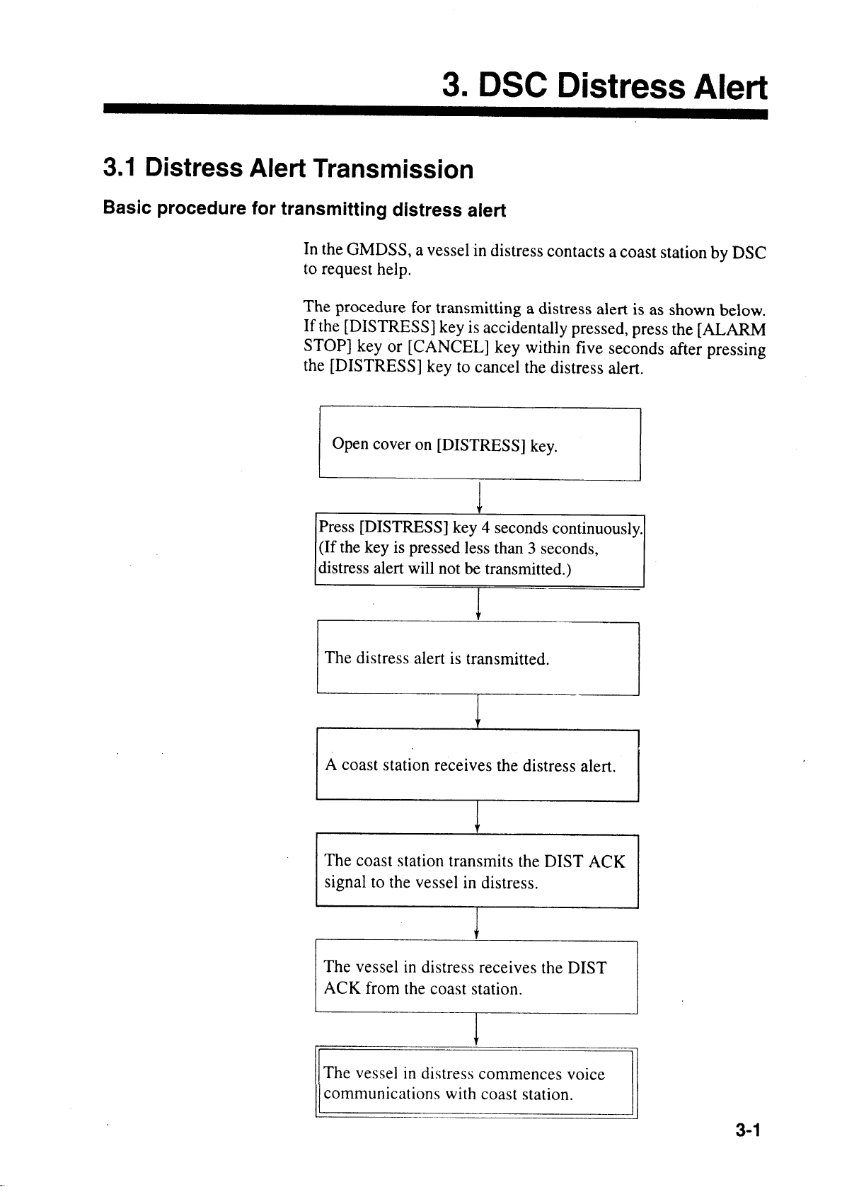
- CANCELLING A FALSE DISTRESS ALERT
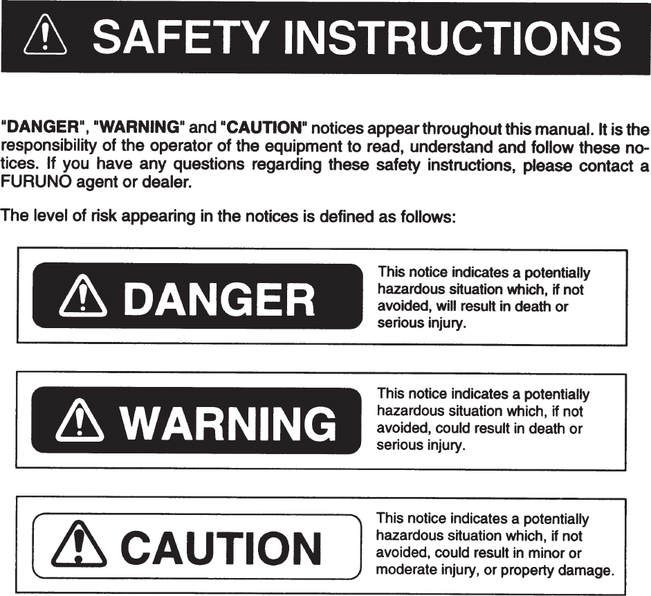
- SAFETY INSTRUCTIONS
- Table of Contents
- FOREWORD
- System Configuration
- 1. VHF Radiotelephone Operational Overview
- 2. DSC Terminal Operational Overview
- 3. DSC Distress Alert
- 4. DSC Communication
- 5. Other Calling Types and Other Functions
- 6. Other Settings
- 7. System Confirmation
- 8. Maintenance & Troubleshooting
- 9. Specifications
- 10. Menu List
- APPENDIX 1 Marine VHF Channel Lists
- APPENDIX 2 Memory Channel List
- APPENDIX 3 Digital Interface (IEC 61162-1 Edition 2)
- INDEX
- Declaration of conformity to type

VHF RADIOTELEPHONE
MODEL FM-8500

Your Local Agent/DealerYour Local Agent/Dealer
9-52 Ashihara-cho,9-52 Ashihara-cho,
Nishinomi
y
a, Ja
p
anNishinomi
y
a, Ja
p
an
Tele
p
hone :Tele
p
hone : 0798-65-21110798-65-2111
Telefax :Telefax : 0798-65-42000798-65-4200
FIRST EDITION :FIRST EDITION : DEC.DEC. 19951995
Printed in JapanPrinted in Japan
A
ll ri
g
hts reserved.
A
ll ri
g
hts reserved.
K :K : MAY.MAY. 17,200217,2002
PUB.No.PUB.No. OME-56030OME-56030
*00080762901**00080762901*
*00080762901**00080762901*
(( TATATATA )) FM-8500FM-8500 * 0 0 0 8 0 7 6 2 9 0 1 ** 0 0 0 8 0 7 6 2 9 0 1 *
*OME56030K00**OME56030K00*
*OME56030K00**OME56030K00*
* O M E 5 6 0 3 0 K 0 0 ** O M E 5 6 0 3 0 K 0 0 *
iiiiiiiiiiiii i
CANCELLING A FALSE
DISTRESS ALERT
1. Switch off transmitter immediately.
2. Switch equipment on and set to Channel 16.
3. Make broadcast to "All Stations" giving your vessel's name, callsign and DSC number,
and cancel the false distress alert.
Example message:
All Stations, All Stations, All Stations
This is NAME, CALLSIGN,
DSC NUMBER, POSITION.
Cancel my distress alert of
DATE, TIME, UTC.
=Master, NAME, CALLSIGN.
DSC NUMBER, DATE, TIME UTC.
ii

iiiiiiiiiiiiiiiiiiiiiiiiiiiiiiiiiiiiiii
iii
Do not disassemble or modify the
equipment.
Fire, electrical shock or serious injury
can result.
Turn off the power immediately if water
leaks into the equipment or the equip-
ment is emitting smoke or fire.
Continued use of the equipment can cause
fire or electrical shock.
Do not place liquid-filled containers on
the top of the equipment.
Fire or electrical shock can result if a
liquid spills into the equipment.
Do not operate the equipment with wet
hands.
Electrical shock can result.
Keep heater away from equipment.
Heat can alter equipment shape and melt
the power cord, which can cause fire or
electrical shock.
Do not open the equipment
except to replace paper or
fuse.
Hazardous voltage which can
cause electrical shock, burn or
serious injury exists inside the
equipment. Only qualified
personnel should work inside
the equipment.
WARNING
Use the proper fuse.
Use of a wrong fuse can result in fire or
permanent equipment damage.
Do not use the equipment for other than
its intended purpose.
Personal injury can result if the equipment
is used as a chair or stepping stool, for
example.
Do not place objects on the top of the
equipment.
The equipment can overheat or personal
injury can result if the object falls.
CAUTION

v
Table of Contents
FOREWORD ......................................................................................vii
System Configuration .....................................................................viii
1. VHF Radiotelephone Operational Overview
1.1 Controls, Indications ..................................................................................................1-2
1.2 Telephone Operation .................................................................................................1-3
2. DSC Terminal Operational Overview
2.1 DSC Messages ...........................................................................................................2-1
2.2 Controls, LEDs...........................................................................................................2-3
2.3 Basic Operation ..........................................................................................................2-5
2.4 Auto Acknowledge .....................................................................................................2-8
3. DSC Distress Alert
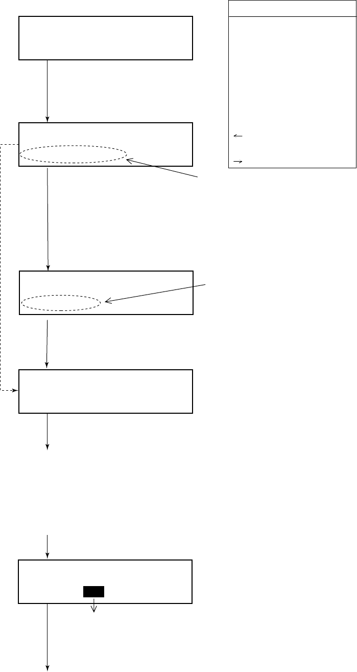
3.1 Distress Alert Transmission........................................................................................3-1
3.2 Manual Entry of Ship’s Position and Time ................................................................3-4
3.3 Receiving Distress Alert from Other Ship..................................................................3-5
3.4 Distress Relay.............................................................................................................3-9
4. DSC Communication
4.1 Transmitting Individual Calls.....................................................................................4-1
4.2 Receiving Individual Call (ACK RQ) ........................................................................4-5
4.3 Transmitting All Ships Calls ......................................................................................4-9
4.4 Receiving All Ships Calls.........................................................................................4-12
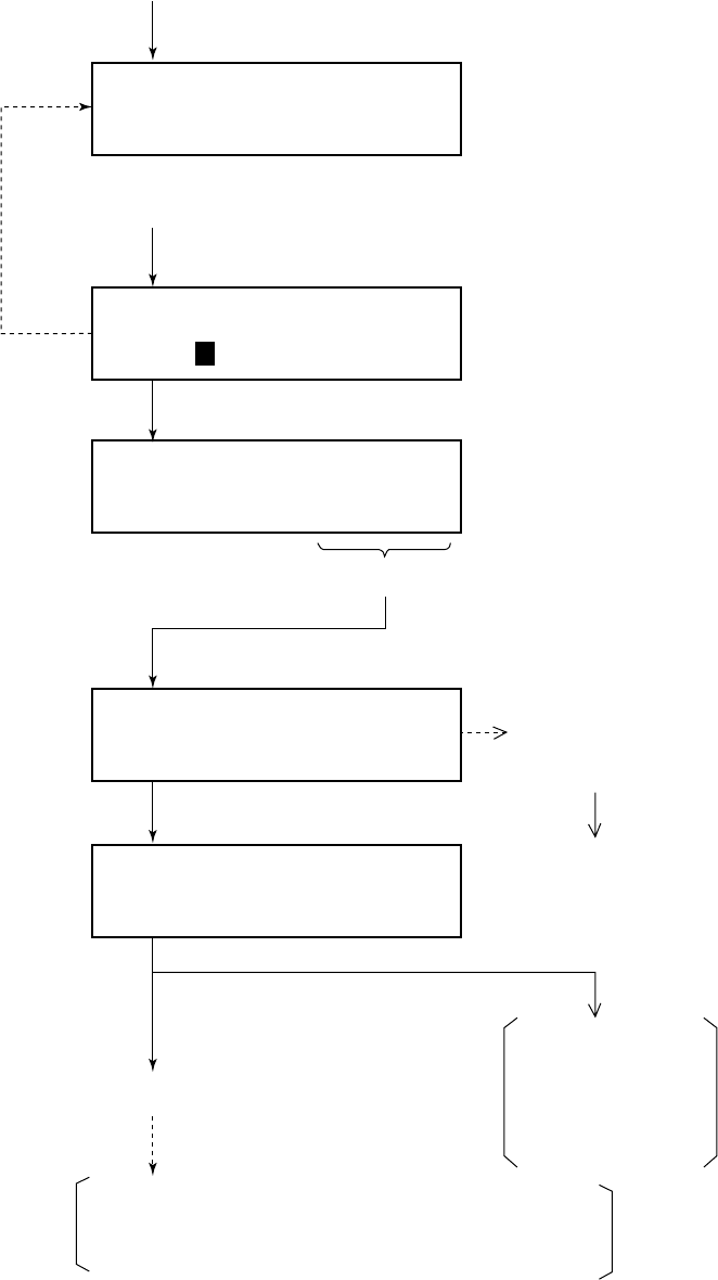
4.5 Creating and Saving Transmit Messages .................................................................4-15
4.6 Writing Over Files ....................................................................................................4-17
4.7 Retrieving, Transmitting Files..................................................................................4-18
4.8 Transmit/Receive Message Memory ........................................................................4-19
5. Other Calling Types and Other Functions
5.1 Other Calling Types....................................................................................................5-1
5.2 Making Telephone Calls.............................................................................................5-4
5.3 Receiving Telephone Call from Coast Station ...........................................................5-7
5.4 Other Station IDs and Telephone Nos. .......................................................................5-8
vi
6. Other Settings
6.1 Printer Setup (Auto/Manual) ......................................................................................6-1
6.2 Turning Keyboard Click ON/OFF..............................................................................6-4
6.3 Aural Alarm Setup ......................................................................................................6-5
7. System Confirmation
7.1 Confirming Own Ship’s ID ........................................................................................7-1
7.2 Confirming ROM Version ..........................................................................................7-2
7.3 Confirming VHF Section Settings .............................................................................7-3
7.4 Confirming VHF Channels ........................................................................................7-4
7.5 Confirming Tx Output Power ....................................................................................7-5
8. Maintenance & Troubleshooting
8.1 Maintenance ...............................................................................................................8-1
8.2 Troubleshooting..........................................................................................................8-1
8.3 Diagnostic Test ...........................................................................................................8-2
9. Specifications
10. Menu List
APPENDIX 1 Marine VHF Channel Lists .................................... AP-1
APPENDIX 2 Memory Channel List ............................................ AP-2
APPENDIX 3 DIGITAL INTERFACE (IEC 61162-1 Edition 2)...... AP-3
Declaration of conformity to type

vii
FOREWORD
Thank you for purchasing this VHF Radiotelephone FM-8500. We
are confident you will discover why FURUNO has become syn-
onymous with quality and reliability.
Dedicated in the design and manufacture of marine electronics
equipment for half a century, FURUNO Electric Company has
gained an unrivaled reputation as a world leader in the industry.
This is the result of our technical excellence as well as our world-
wide distribution and service network.
Please carefully read and follow the safety information and oper-
ating and maintenance instructions set forth in this manual before
attempting to operate the equipment and conduct any maintenance.
Your VHF Radiotelephone FM-8500 will perform to the utmost of
its ability only if it is operated and maintained in accordance with
the correct procedures.
Features
The FM-8500 is a highly advanced, semi-duplex, fully synthesized
25W VHF transceiver with DSC terminal, designed to satisfy the
stringent requirements of marine communications. It complies with
GMDSS carriage requirements for safety and general communica-
tions.
• Conforms to the following standards and regulations:
IMO A. 694(17)
IMO A. 803(19)
IMO A. 524(13)
IMO MSC 68(68), MSC/Circ.862
IEC-61097-3/7/8
IEC-60945 (3rd edition)
IEC-61162-1
ETS 300 338, 301 033, 300 162
ITU-R M.493-9, M.541-8, M.689-2
• Automatic position and time input and update with connection
of EPFS (Electronic Position-Fixing Equipment).
• Optional printer can automatically print out received messages
and test results.
• Log stores 50 each of latest ordinary, distress and transmitted
messages, in separate memory blocks.
• One-touch testing facility.
Program number
DSC 0550182010 (version 1.12)
RT 0550183006 (version 1.06)
viii
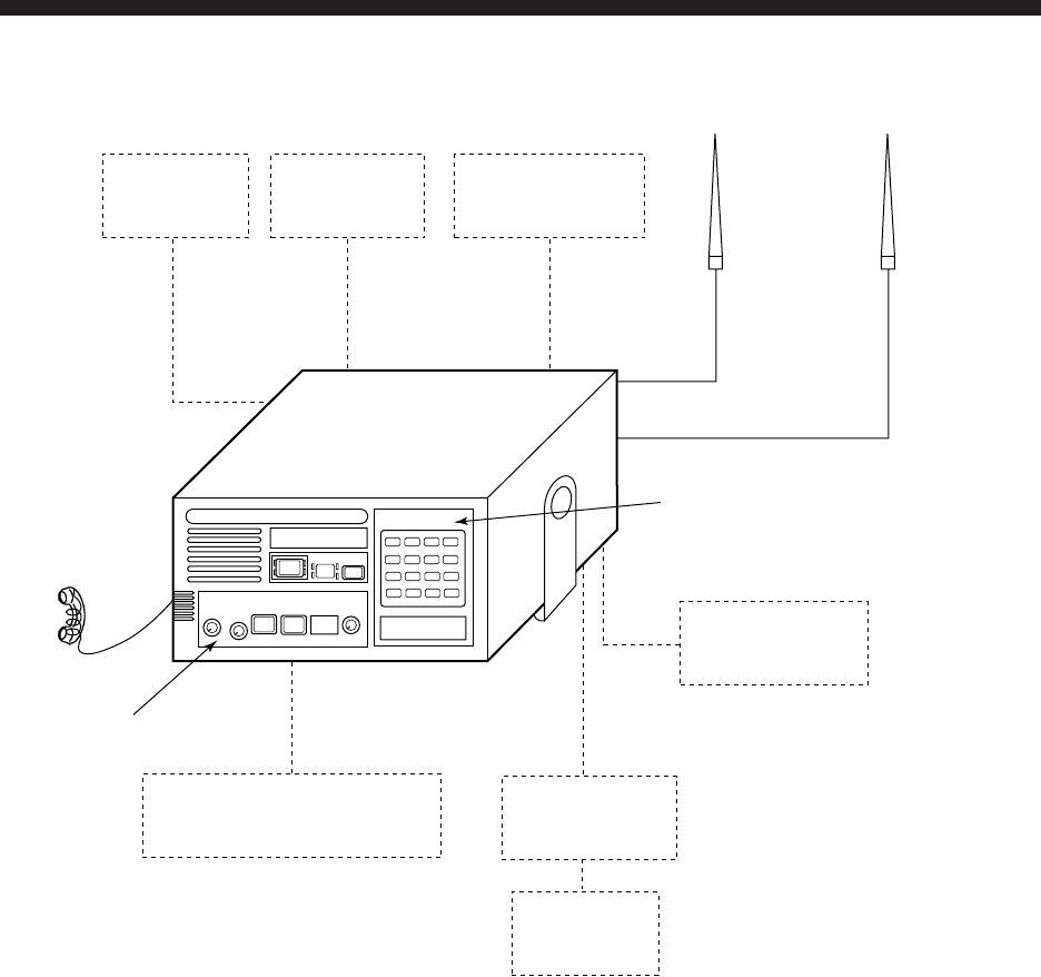
System Configuration
External
Speaker Power Supply
PR-300
Distress Message Controller
DMC-5
Printer
FM-8500
CH70 Antenna VHF Antenna
Handset
MIC Receptacle
Box
Position-fixing
Equipment
DSC Section
VHF Section
Printer Interface
IF-8500
Figure 1 FM-8500 system configuration
This page is intentionally left blank.
1-1
1. VHF Radiotelephone
Operational Overview
The FM-8500 system consists of a main transceiver unit and two
antennas. The transceiver unit contains a VHF transmitter, receiver,
and channel 70 watch receiver module. The performance and op-
eration are controlled on its front panel. The antenna may be of
any type available from FURUNO or market and the recommended
type is a vertically polarized non-directional type. The first an-
tenna works for transmitting and receiving and the 2nd antenna for
watch keeping.
1
DISTRESS ALARM
STOP
POSITION
DISTRESS CANCEL
2
AUTO ACK
3
TEST
CANCEL
4
PRINT
5
CONTRAST
6
VOLUME
7
FILE
8
RCVD
9
XMTD
SELECT
0
ENT
VHF RADIOTELEPHONE FM-8500
Watch CH 70
auto
CH16
TX CHANNEL
MODE(PUSH)
REM USA WX PRIV
HI
LOW
LOW
AUTO
CALL
SQUELCH
OFF/DW/SCAN(PUSH)
OFF
(PUSH)
VOLUME
Volume with
Power ON/OFF
(Press to turn on/off
loudspeaker.) Squelch control
(Press for DW, Scan)
High/Low power
CH16 key
LCD Keyboard
(for DSC operation)
Channel No. display
Channel selector
(Press for Mode selection)
Controls for
VHF operation
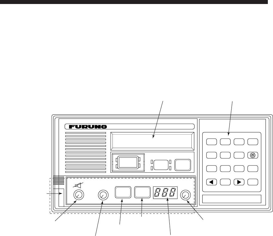
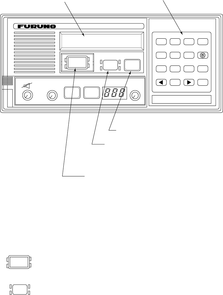
Figure 1-1 FM-8500 transceiver unit

1-2
1.1 Controls, Indications
Controls
CHANNEL/ Selects a channel. Pressing the Channel Selector
MODE (rotary control) changes the mode from INTL,
USA, WX, and PRIV in this order. (Appears when
USA/WX and PRIV mode are registered.)
SQUELCH/ Mutes the receiver when no signal is present on
DW/SCAN the channel selected. Auto position automatically
reduces white noise.
Pressing the control changes the operating modes:
Dual watch, Scan and Off.
VOLUME/ Turns the power on or off and adjusts the volume
of the built-in loudspeaker.
Pressing the control turns the loudspeaker on or
off.
HI/LOW key Alternates high or low output power.
CH16 key Selects channel 16.
Indications
The display shows the following indications;
LOUDSPEAKER
noitacidnInoitcnuF
EMULOVehtgnisserpyb,FFOrekaepsduollanretnI denrutyllacitamotuasirekaepsduollanretnI.lortnoc .pudekcipsitesdnahehtrevenehwffo
WOL.rewopFRwolrofsthgiL
XT.gnittimsnartelihwsthgiL
MER 007-BRyblortnocrednusi0058-MFnehwsthgiL
.noitatSetomeR
ASUsadesueraslennahcxelpudUTIemoS(.edomASU
).slennahcxelpmis
XWelbaliavA(.detcelessilennahcrehtaewanehwsthgiL
).noisrevSUni
NACS/WD.gninnacsrofNACS;hctaWlauDrofWD

1-3
1.2 Telephone Operation
Turning the power on and off
To turn the power on, turn the VOLUME control clockwise until
you hear a click. To turn the power off, turn the control fully coun-
terclockwise until you hear the click.
Selecting channel modes
While pressing the channel selector, press the CH16 key to select
the channel mode, International, USA (in the case of USA ver-
sion), private (if authorized), or weather mode (USA version). The
International version of FM-8500 has no such selection.
On the weather channel mode, a beep is emitted when the weather
alert tone is received.
NOTE: Private channels are available only where permitted by
the authorities.
Selecting channels
Rotate the CHANNEL selector clockwise (counterclockwise) un-
til a desired channel is reached.
Adjusting volume
The VOLUME control adjusts the volume of the loudspeaker.
Adjusting squelch
The SQUELCH control adjusts the squelch threshold level. Adjust
it so that white noise heard in the loudspeaker just fades out. Per-
form this operation when no traffic is being received. AUTO squelch
automatically reduces white noise. Usually select "AUTO" posi-
tion. Avoid turning the squelch too far clockwise: you may miss a
long distance communication.
Note: To obtain correct scan watch/dual watch response, adjust
the SQUELCH control precisely.
Every press of the SQUELCH control changes the function as fol-
lows:
OFF DW SCAN

1-4
Transmitting
Press the PTT (Press-to-talk) switch on the handset or microphone
to talk, and release it to listen for the response.
Output power
• BEFORE transmitting, think about the subjects which have to be commu-
nicated and, if necessary, prepare written notes to avoid unecessary inter-
ruptions and ensure that no valuable time is wasted on a busy channel.
• Listen before commencing to transmit to make certain that the channel is
not already in use.
Each press of the [HI/LOW] key selects HI or LOW output power.
The transmitter power is automatically set for low on the follow-
ing channels.
International: CH15, CH17
USA: CH13, CH15, CH17, CH67; to operate USA chan-
nel 13 or 67 in high power, keep [HI/LOW]
pressed while talking into the handset.
Turning the loudspeaker on/off
To turn the loudspeaker on/off, press the VOLUME control. The
loudspeaker off mark appears when the speaker is off. The loud-
speaker is automatically turned off when the telephone handset is
used on semi-duplex channels.
Channel 16
Press the [CH16] key to select channel CH16, International Call-
ing and Safety Channel.
This is an international calling and safety channel. The use is lim-
ited for distress, safety and calling. The transmission on CH16
(156.800 MHz) should be limited to within 1 minute except for
distress calling.
Avoid calling on Channel 16 for purposes other than distress, ur-
gency and very brief safety communications when another calling
channel is available.

1-5
Dual watch
The dual watch allows you to keep watch on channel 16 and an-
other channel. CH16 and another channel are watched at intervals
of 0.15 seconds and one second, respectively.
To start DW, press the SQUELCH control once. When the receiver
finds a signal on channel 16, it locks on CH16 and restarts dual
watching after the signal on CH16 has gone. If another channel
has traffic, it still continues dual watch. The speech is heard inter-
mittently. If you are annoyed with the intermittence, turn off DW
by pressing the PTT switch on the handset or pressing the
SQUELCH control.
Scanning
The receiver scans all channels in the selected channel mode in
ascending channel order, watching CH16 between channels as be-
low:
To start scanning, press the SQUELCH control and SCAN is started.
When the receiver finds a signal, scanning is stopped on that chan-
nel and starts dual watch on it and channel 16.
Time-out-timer (U.S.A. type only)
The FM-8500 is equipped with an automatic timing device that
deactivates the transmitter and reverts the transceiver to the re-
ceive mode after an uninterrupted transmission period of 5 min-
utes.
Remarks on voice communications
Automatic acknowledge is automatically changed to manual ac-
knowledge when voice communications begin. (The "auto" indi-
cation, however, remains on the screen.) This is done to prevent
break in communications. Automatic acknowledge is automatically
restored once voice communications are terminated.
Priority
The priority of the equipments is as follows.
DSC section of FM-8500 > Wing handset > Handset of FM-8500
> Remote Station RB-700
116 2 16 3 16 4…
16 88 16 87 16 86 16…
This page is intentionally left blank.

2-1
2. DSC Terminal
Operational Overview
2.1 DSC Messages
The contents of a DSC message change with format specifier (call-
ing category).
1. Format: Calling type
IND: Individual Call
TEL: Telephone Call
ALL: All Ships Call
R/A: Relay All Ships Call
R/S: Relay Specific Ships Call
GRP: Group Call
POS: Position Request Call
2. Address: Station’s 9-digit ID number
IDs starting with “00” are coast stations, those starting with “0”
are group IDs or another IDs are ship’s IDs.
3. Category: Communication priority
There are four communication priorities as below:
DIS: A vessel is in grave and imminent danger and requests im-
mediate assistance.
URG: Announce important safety information or request medical
assistance.
SAF: Transmitting a message containing an important navigational
or an important meteorological warning.
ROU: For routine (individual) calling.
4. DSC: DSC channel
A DSC channel is different from the usual communication channel
because it is not used for voice communication but rather DSC and
acknowledging receipt of message.
5. Telecom1: Telecommand
The communication mode; simplex or semi-duplex.
2-2
6. Channel: Voice communication channel
To communicate with a coast station, a station sends its position
data to the coast station and the coast station determines the chan-
nel to use. A station may only use CH16 (distress channel) in the
event of distress.
7. Pos: Ship’s position
Position input by radionavigational equipment.
8. UTC: Universal Time Coordination
The equipment contains a clock. External time input from
radionavigational equipment cannot be used.
9. ACK RQ (BQ):
Acknowledge request (RQ) or acknowledge reply (BQ).
2-3
2.2 Controls, LEDs
Controls
Figure 2-1 FM-8500 transceiver unit
LEDs
The four LEDs surrounding the [DISTRESS] key light when the
key is pressed, 4 seconds continuously.
• The upper two of the four LEDs surrounding the [ALARM
STOP] key blink (and alarm sounds) when distress or urgent
message is received. LEDs can be extinguished and alarm si-
lenced by pressing the [ALARM STOP] key.
• The lower two LEDs (Green) blink (and alarm sounds) when
message other than distress/urgent are received. Alarm is auto-
matically silenced five seconds after message is received.
DISTRESS
ALARM
STOP
1
DISTRESS ALARM
STOP
POSITION
DISTRESS CANCEL
2
AUTO ACK
3
TEST
CANCEL
4
PRINT
5
CONTRAST
6
VOLUME
7
FILE
8
RCVD
9
XMTD
SELECT
0
ENT
VHF RADIOTELEPHONE FM-8500
Watch VHF ch70
auto
CH16
TX CHANNEL
MODE(PUSH)
REM USA WX PRIV
HI
LOW
LOW
AUTO
CALL
SQUELCH
OFF/DW/SCAN(PUSH)
OFF
(PUSH)
VOLUME
LCD DSC controls
Transmits messages other than distress.
Silences the receive alarm.
Stops repetitive alerts.
Transmits the distress alert. Open cover on
[DISTRESS] key and press the key 4 seconds
continuously.
2-4
1
POSITION
2
AUTO ACK
3
TEST
CANCEL
4
PRINT
5
CONTRAST
6
VOLUME
7
FILE
8
RCVD
9
XMTD
SELECT
0ENT
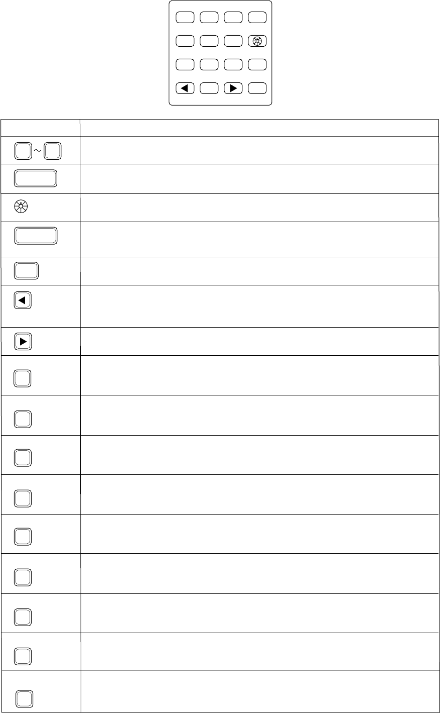
Key Function/Purpose
0 9 Enter numeric data.
Cancels wrong data and restores previous menu.
Adjusts illumination of LED and keys in four levels.
Registers key input. (Blinking item is registered when key is pressed.)
Shifts the cursor rightward.
Ship’s position and time are shown while pressed and held down.
Conducts self-tests.
Printing. (This is also available for automatic setting of the printer.)
Adjusts contrast of LCD in eight levels.
Retrieves files.
Displays contents of received messages (Storage capacity: 100 files, 50 each
of distress and other). (Refer to page 4-21.)
Displays contents of transmitted messages (Storage capacity: 50 files).
(Refer to page 4-19.)
Turns automatic transmission of acknowledge call (AUTO ACK) on/off. (Refer
to page 2-8.) Note that distress alert cannot be automatically acknowledged
by “auto acknowledge”.
1. Display “Set up menu” (Main menu).
2. Changes settings of items appearing with blinking question mark.
1. Shifts the cursor leftward.
2. Restores previous display when pressed at displays with a blinking
question mark.
CANCEL
SELECT
ENT
1
POSITION
2
AUTO ACK
3
TEST
4
PRINT
5
CONTRAST
7
FILE
8
RCVD
9
XMTD
6
VOLUME Not used.
Figure 2-2 Keyboard
2-5
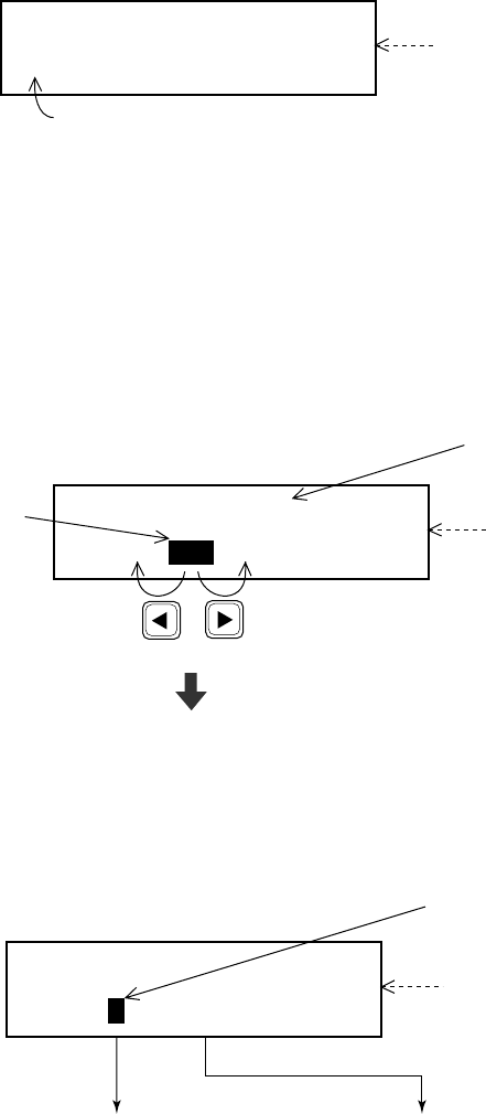
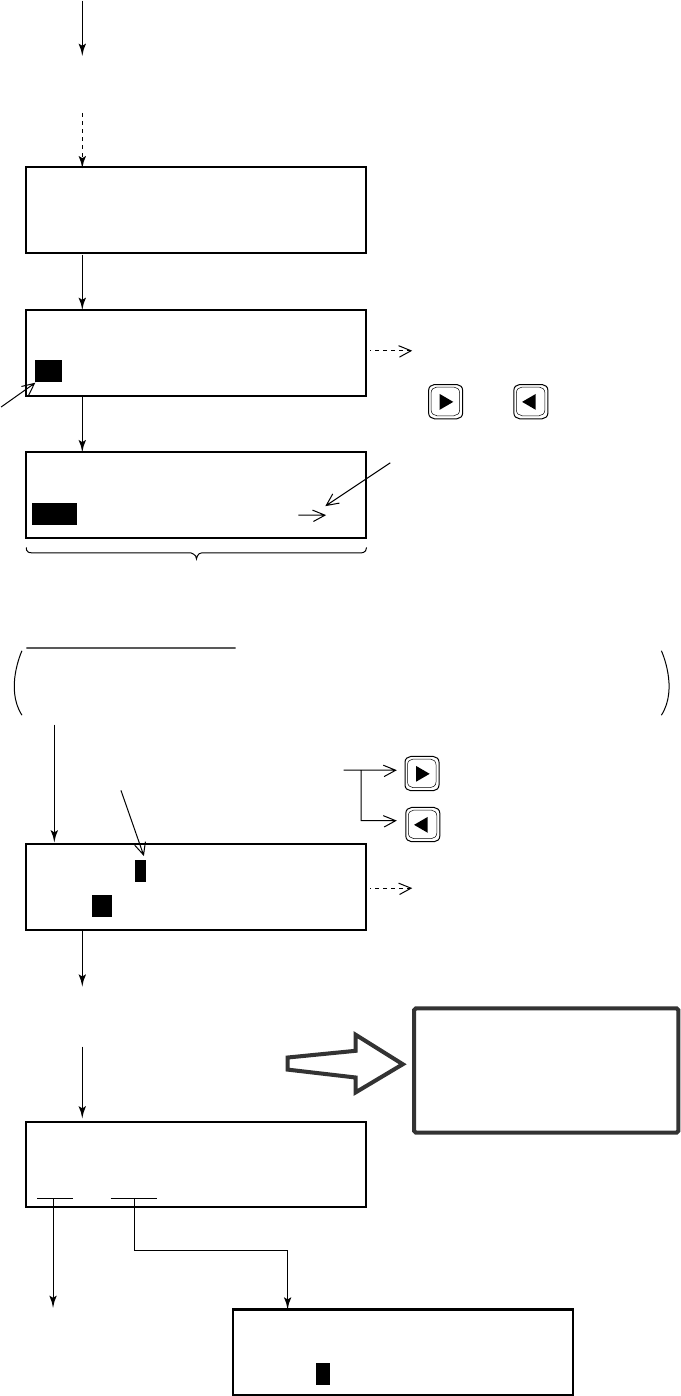
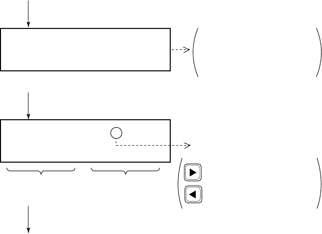
2.3 Basic Operation
Normal display
When the FM-8500 is turned on, the following display appears.
This display is known as the “normal display.”
Should you get lost in operation you can return to the normal dis-
play by pressing the [CANCEL] key several times.
Selecting and registering items
The arrow keys ( [t] and [s] ) function to select items on the LCD.
After selecting item, press the [ENT] key to register it.
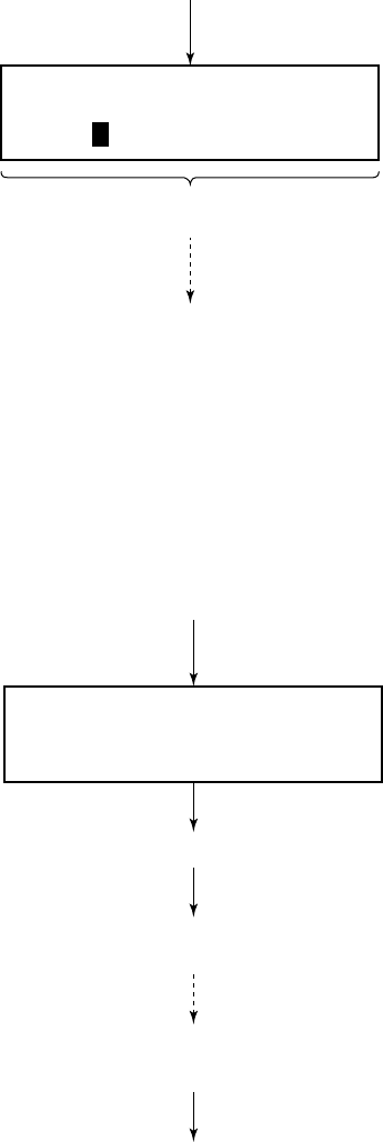
When blinking question mark appears
Press the [ENT] or [SELECT] key depending on your desire.
Watch VHF CH70
auto
Normal display
screen
[2] key pressed to get “auto” screen.
Call type <ALL ships>
IND TEL ALL R/A ---
Call type
selection screen
(In this example
it is “Call type”.)
Item selected by cursor
appears here.
(Shifts
cursor
leftward.)
Press the [ENT] key.
Blinking
cusor
encloses
current
selection. (Shifts
cursor
rightward.)
* VHF call message *
Format ? INDIVIDUAL
Format selection screen
(In this example it is format
for “VHF call message”.)
Blinking question mark
• If change is necessary,
press the [SELECT] key. • If no change is necessary,
press the [ENT] key.
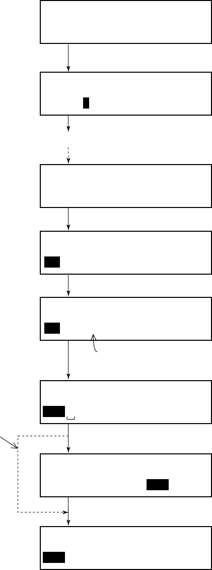
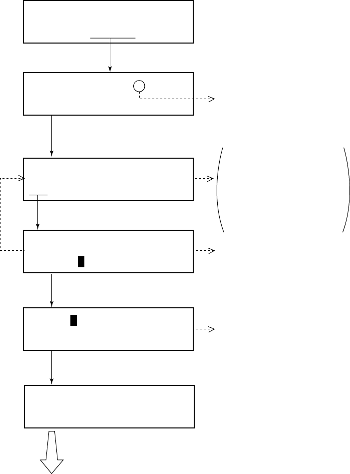
2-6
Preparing and Transmitting Messages
There are two methods by which you can prepare and transmit
messages, and they are shown below.
Preparing message for immediate transmission
Prepare message and then transmit it.
Preparing and storing message for later transmission
Prepare messages excluding distress message and save them to the
memory. (Maximum 99 files) You may retrieve and transmit a
memory-stored message as follows.
* VHF call message *
Format? INDIVIDUAL
Normal display
For how to prepare a message, refer
to page 4-1.
After preparation, press the [CALL]
key to transmit the message.
Press the [ENT] key.
Set up menu < >
1 2 3 4 6 7 9 ALM
Normal display
For how to prepare and store a message, refer to “4.5 Preparing
and Saving Transmit Messages”.
Press the [7] key.
After the normal display appears, press keys in the order
shown below to transmit a message.
Press the [7] key. / (Enter file number.) / Press the [CALL] key.
Press the [SELECT] key.
2-7
Status of FM-8500 during DSC Call
When the distress alert is transmitted (by pressing the [DISTRESS]
key), the output power of the FM-8500 is automatically set to maxi-
mum (25 W).
Key entry of VHF
The FM-8500’s keyboard accepts no key input while DSC mes-
sage is transmitted. (Distress call: inoperative about 3 seconds, other
calls: inoperative about 0.5 seconds.)
To unlock it manually, if necessary, press the [CANCEL] key.
The VHF section keyboard accepts no key input when the PTT
switch is operated.
2-8
2.4 Auto Acknowledge
Auto acknowledge functions to automatically acknowledge indi-
vidual calls. Press the [2] (AUTO ACK) key to automatically trans-
mit the acknowledge back (ACK BQ) to the sending station when
an individual call is received.
An individual message cannot be automatically acknowledged
when it is received while the handset is off hook.
When auto acknowledge is disabled
• Automatic acknowledge is disabled when an Error Checking
Code (ECC) appears at the end of a receive message.
• A distress alert is received.(A distress alert cannot be acknowl-
edged automatically.)
Turning & AUTO ACK on/off
Each press of the[2] key enables/disables auto acknowledge func-
tion..
“auto” function
Provides automatic acknowledge of individual calls. Automatic
acknowledge, however, is disabled when conducting voice com-
munications.
“manual” function
Manual acknowledge of all calls. However, an all ship’s call is
automatically acknowledged when no voice communications are
taking place when the call is received. See page 4-12 for details.
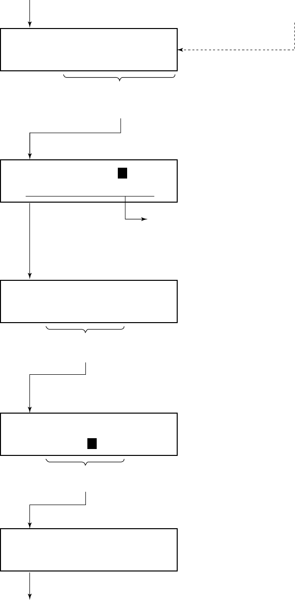
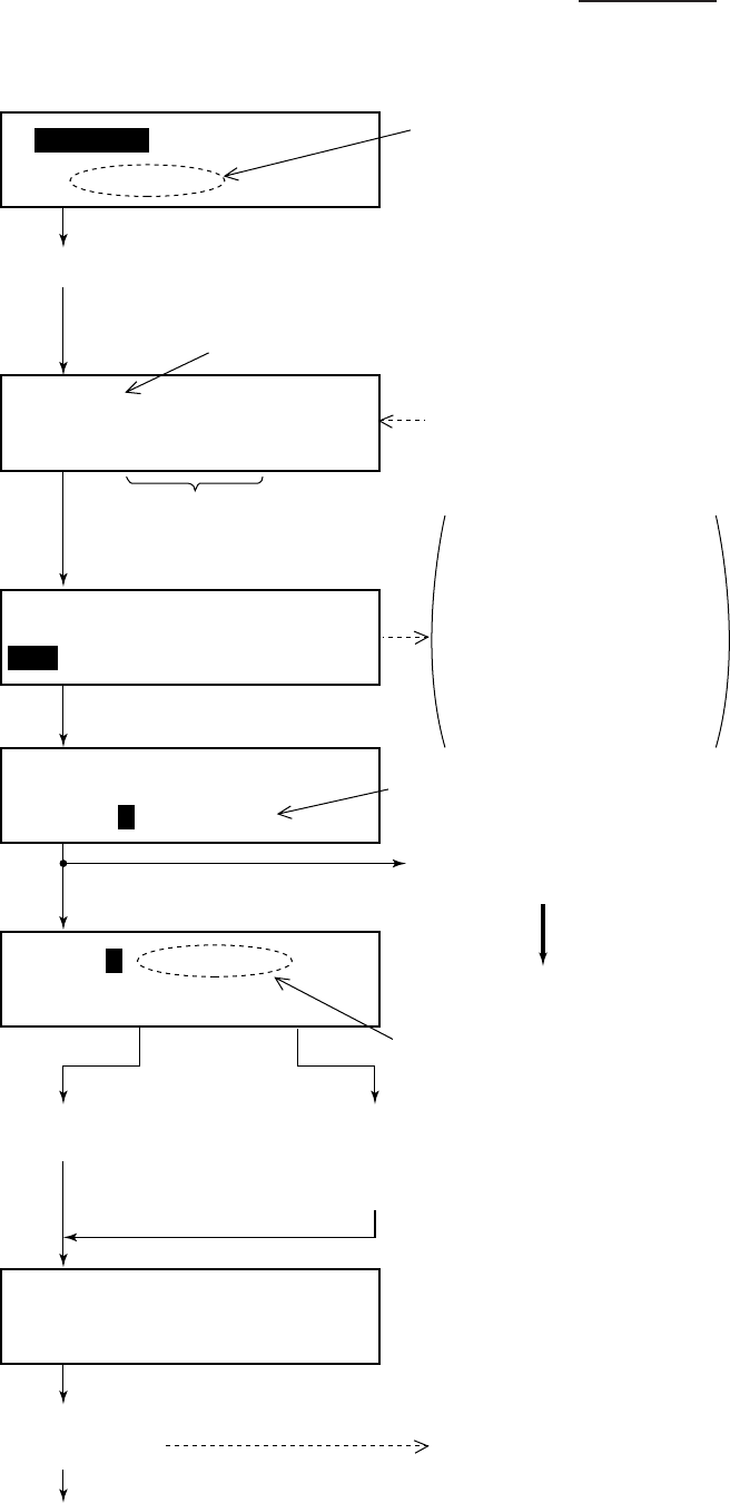
3-2
Transmitting the distress call
Watch VHF CH70
auto
DISTRESS CALL CH70
34° 40N 135° 20E at 15:20
To announce nature of distress, press appropriate key
for nature of distress within 3 sec. after pressing the
[DISTRESS] key. Continue pressing [DISTRESS] key 4
sec.
Transmission time is about three seconds.
If wrong nature of distress is input, enter correct
nature within 3 seconds.
If no numeric
key is pressed,
distress alert is
automatically
transmitted.
DISTRESS CALL Nature?
UNDESIGNATED
* Call in progress *
DISTRESS CALL CH70
Nature of Distress
Position/Time
Nature of Distress
(Transmitting)
* Wait for dist ack *
Next CH70 3.7 min (Waiting for distress
acknowldege)
(continued on next page)
A coast station will transmit a DIST ACK signal to you to confirm the
distress alert. Once you have received the DIST ACK signal, CH16
(Distress, Safety and Calling frequency) is automatically selected so
that you may commence voice communications with the coast
station. After the [DISTRESS] key has been pressed, no further
operation of the radiotelephone is required until you have received
the DIST ACK signal.
1 Open cover on [DISTRESS] key.
2 Press [DISTRESS] key 4 seconds
continuously.
Counts down. If distress call is not
acknowledged it is automatically
retransmitted until acknowledged.
(Do nothing until own ship receives DIST
ACK.)
[1]: Fire, explosion
[2]: Flooding
[3]: Collision
[4]: Grounding
[5]: Listing, capsizing
[6]: Sinking
[7]: Disabled & adrift
[8]: Abandoning
[0]: Undesignated
[ ]: Piracy/armed
robbery attack
[ ]: Man overboard
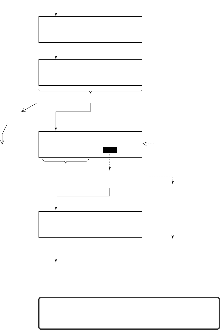
3-3
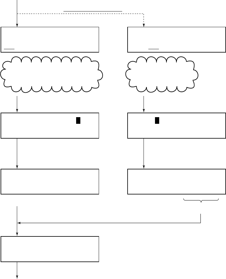
Commence voice communications with coast station on CH16.
* Received * DISTRESS ACK
ID : 001234567
ID of station (usually coast station)
which transmitted DIST ACK.
(from previous page)
1. Provide the following information to the coast station:
(1) Speak slowly and distinctly, “MAYDAY, MAYDAY, MAY-
DAY”, pronounced as the French expression “m’aider”.
(2) This is;
(3) The name of your vessel and call sign three times.
Then, begin the distress communications, which consists of:
(1) Position in latitude and longitude;
(2) The name of the distress;
(3) The kind of assistance desired;
(4) Any other information which might facilitate rescue, for
example, length, color, and type of vessel, number of per-
sons on board.
2. Indicate the end of message by saying “Over”.
Some countries do not have sea area A. In this case "ACK" from
the coast station does not arrive over DSC. A ship nearby will con-
tact the vessel in distress over CH16. After transmitting the dis-
tress alert conduct voice distress communications as shown above.
Distress call
Distress communications
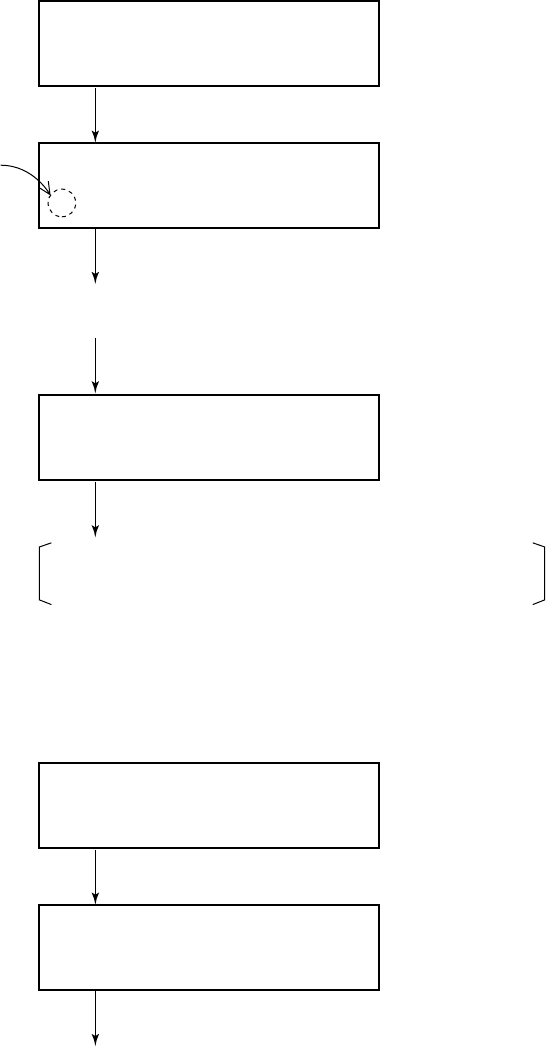
3-4
3.2 Manual Entry of Ship’s Position and Time
Entering data manually
If automatic position input is lost for one minute the message "EPFS
error" appears. In this case, enter position manually as below.
Note: If the manually entered position is not updated within four
hours the buzzer sounds and the message "Warning: Update posi-
tion!" appears on the screen. And if not updated within 23.5 hours
the position entered is erased. Once automatic input of position is
restored, cancel manually entered position as below.
Confirming Ship's Position and Time
Press and hold down the [1] (POSITION) key, ship's position and
time are shown while the key is pressed.
Canceling manually entered data
To cancel the manually entered data, enter 9999 for the time and
press the [ENT] key.
Note: Above procedure may also be used when you do not know
your ship's position. This data is input as NO INFORMATION in
POS&TIME in the DISTRESS ALERT MESSAGE.
Position < >
NORTH= ˚ S E= ˚ W UTC= :
Enter time
(UTC).
Press the [ENT] key.
(Returns to normal
display.)
To move blinking cursor from NORTH
position to SOUTH, press the [s] key.
Enter
longitude.
Enter
latitude.
Press [ENT], [ENT]
[SELECT] in this order.
Watch VHF CH70
(Normal display)
* VHF call message *
Format: DISTRESS To enter data manually
from the Distress Alert
message, press [ENT]
and select call type
Distress. Press the [SELECT] key
followed by the [1] key.
3-5
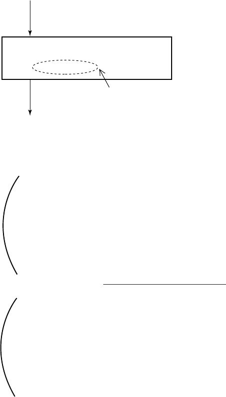
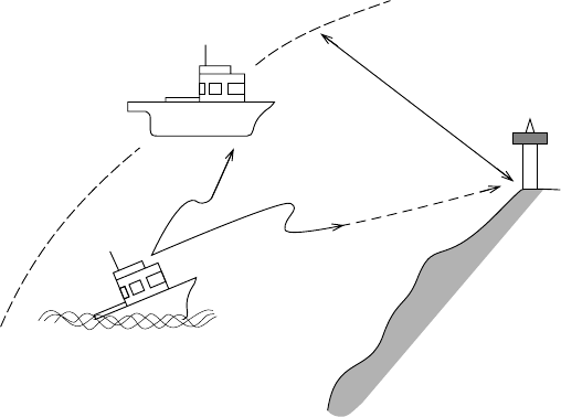
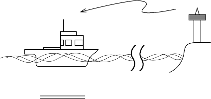
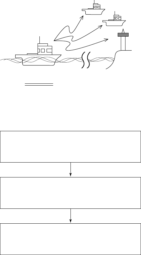
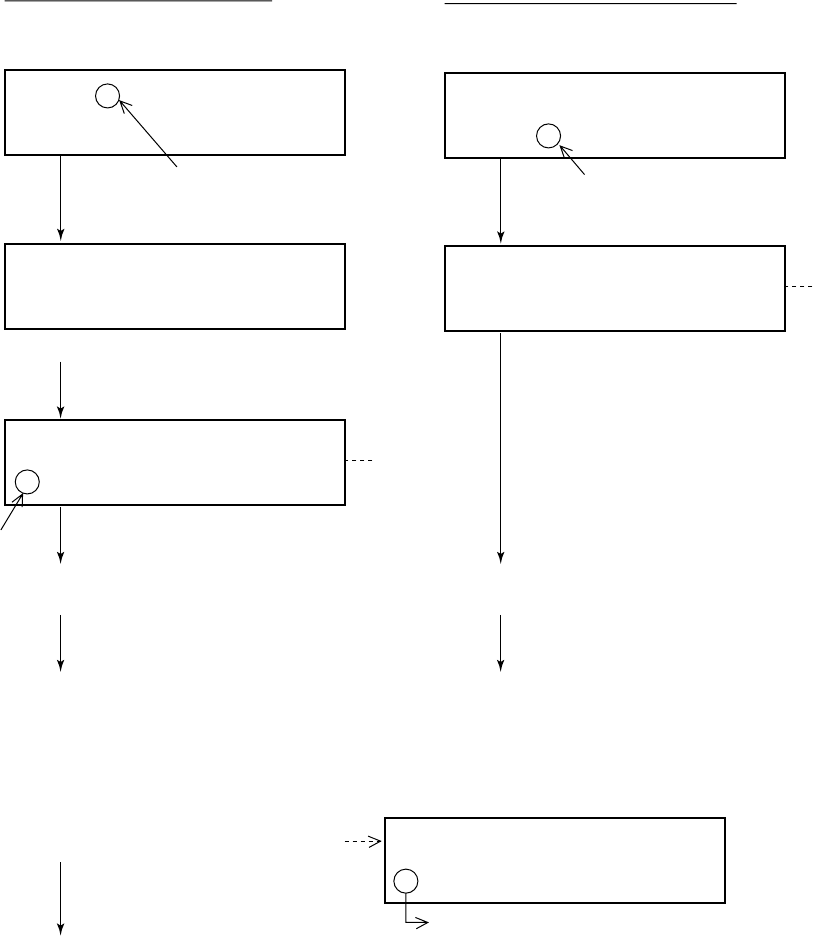
3.3 Receiving Distress Alert from Other Ship
In no case is a ship permitted to transmit a DSC distress relay
call on receipt of a DSC distress alert on VHF channel 70.
Conditions necessary for relaying distress alert:
1 When the station in distress is not itself in a position to transmit
the distress message, or
2 When the master or person responsible for the vessel not in
distress, or the person responsible for the coast station, consid-
ers that further help is necessary.
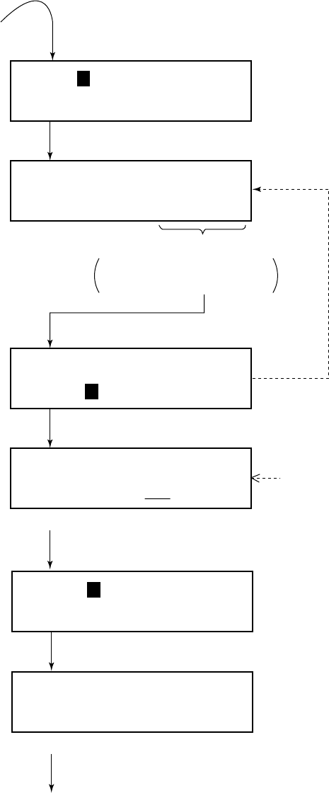
Procedure when in area A1
1. When the FM-8500 receives a distress alert from another ves-
sel the upper two LEDs (Red) near the [ALARM STOP] key
blink and the FM-8500 sounds the distress alarm.
2. Silence the alarm by pressing the [ALARM STOP] key.
3. Wait up to three minutes until the DIST ACK signal from a
coast station is received. Be prepared to follow the instructions
of the coast station.
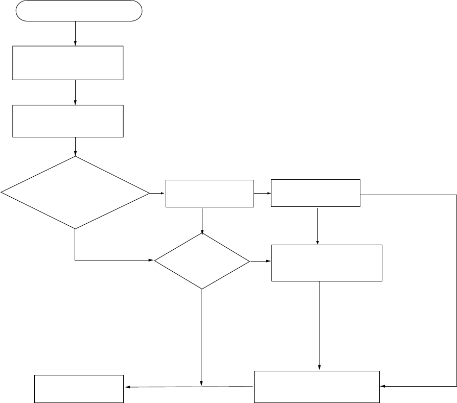
4. If you do not receive the DIST ACK signal, follow the flow
chart shown on the next page.
If further DSC alerts are received from the same source and the
ship in distress is beyond doubt in the vicinity, a DSC
acknowledgement may, after consulation with an RCC or Coast
Station, be sent to terminate the call.
Note 1: An asterisk (*) in a received distress alert message indi-
cates error or unknown at the location marked with the asterisk.
Note 2: Do not send DISK ACK in response to receipt of distress
alert having a nature of distress of EPIRB emission.
About 20 to 30 miles
(Sea area A1)
Your Ship
Coast station
Distress Alert
Transmission
Vessel in Distress
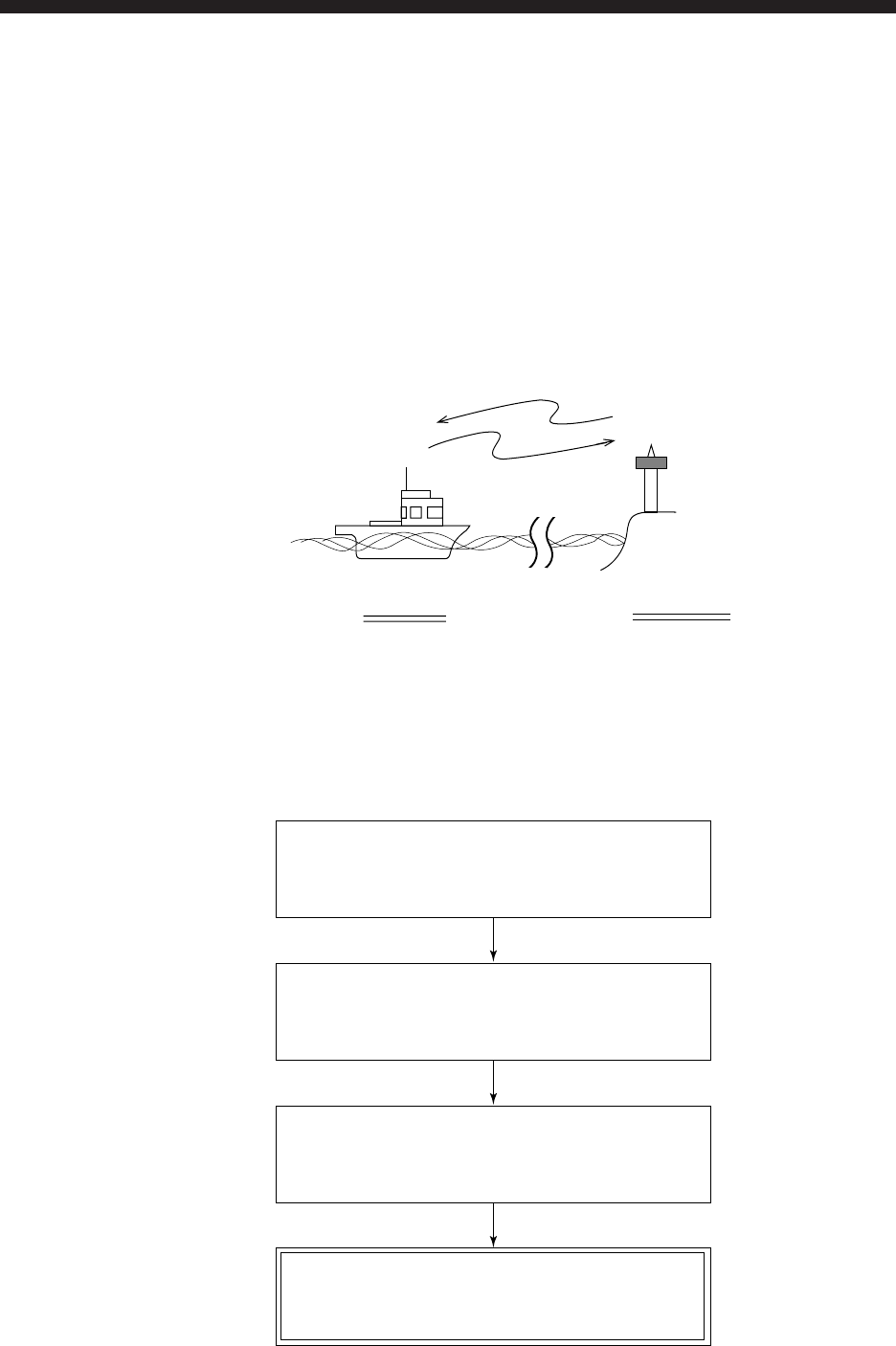
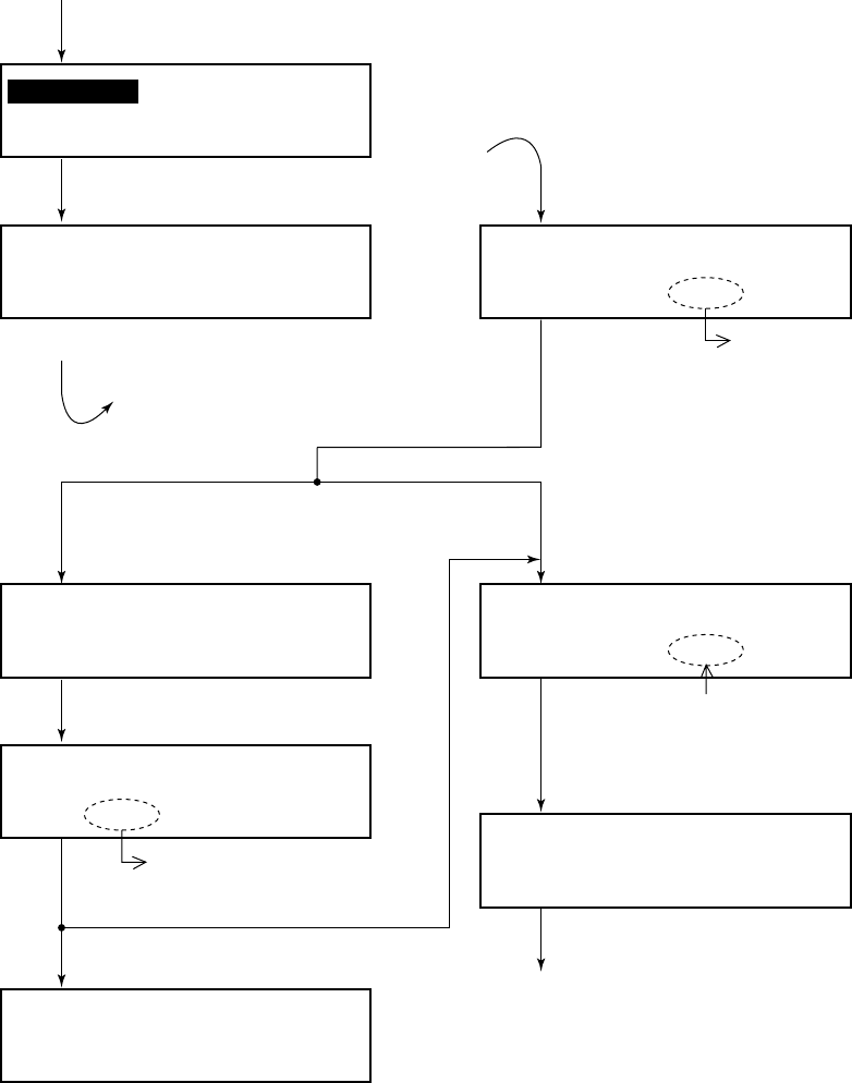
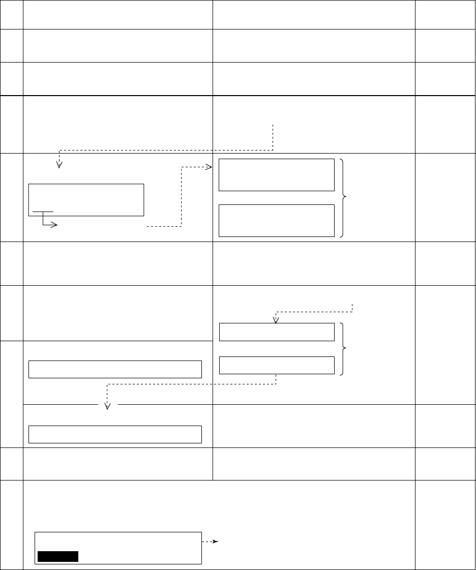
3-6
Press [ALARM STOP]
key to silence alarm.
DSC Distress alert received.
Listen on CH16 for
5 minutes.
Did you receive
acknowledge from
CS and/or RCC?
Is own
vessel able
to assist?
No
Is distress traffic
in progress?
No
Is distress call
continuing?
Acknowledge the alert by
radiotelphony to the ship
in distress on VHF CH16.
Yes
No
Inform CS and/or RCC.
Yes
Yes Yes
Enter details in log.
No
CS = Coast Station
RCC = Rescue Co-ordination Center
1. Say "MAYDAY" ONCE.
2. Say ID number of vessel
in distress THREE TIMES.
3. Say "This is" ONCE.
4. Say ID number of your vessel
THREE TIMES.
5. Say "Received MAYDAY"
ONCE.
Flow chart - Action by ships upon reception of VHF DSC distress alert
3-7
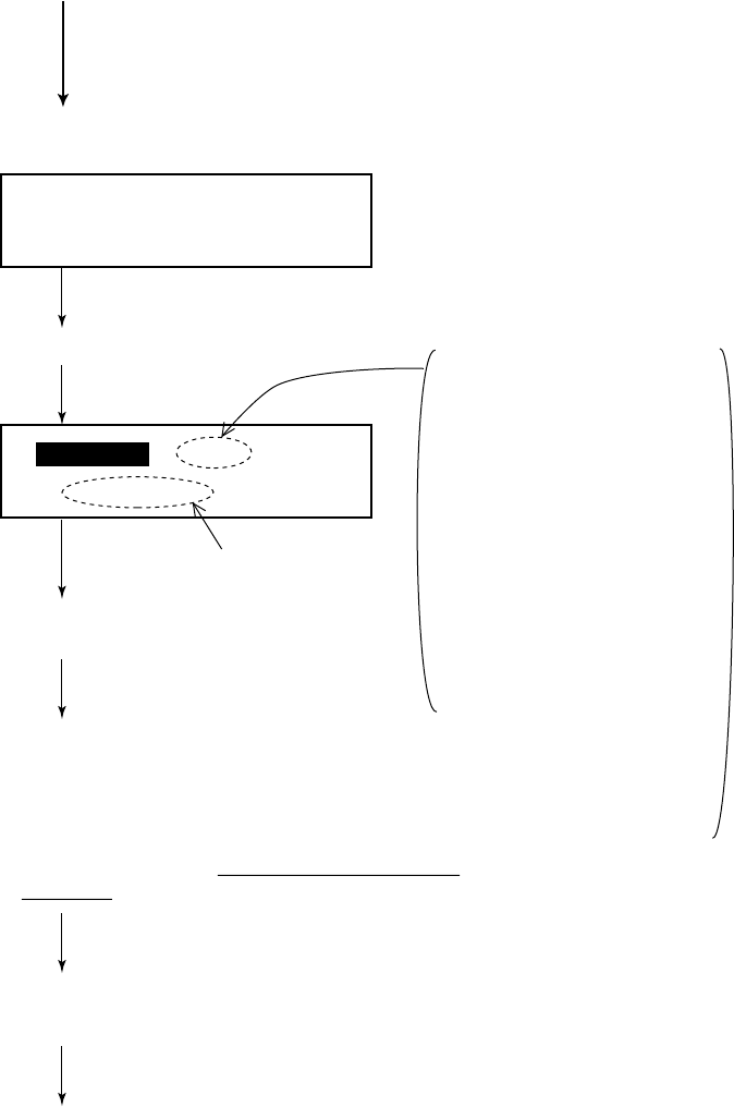
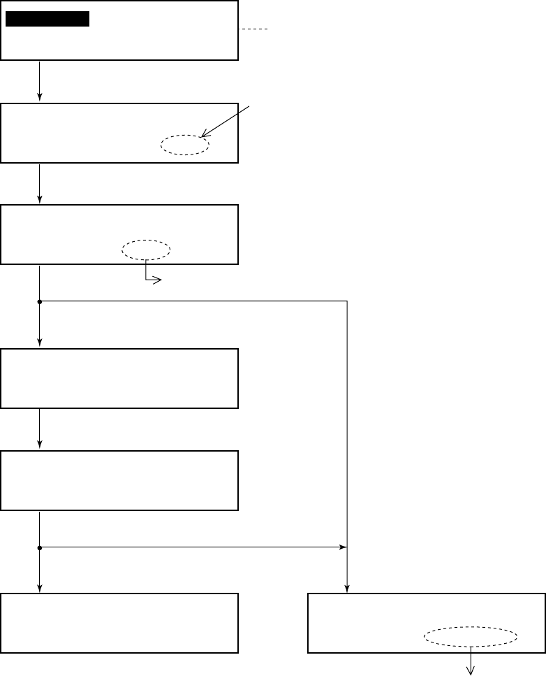
Transmitting DIST ACK over CH16
Select VHF CH16 and transmit DIST ACK to vessel in distress.
Relay the distress alert to a coast station by DSC. Follow the instructions
of the coast station.
Transmit DIST ACK to vessel in
distress over DSC CH70. Communicate with vessel in distress.
No reply Reply received
Begin search and rescue operation for the vessel in distress.
3-8
* Received * DISTRESS CALL
ID: CH70
Acknowledge call < >
ACK RELAY END ---
* Ready for calling *
DIST ACK CALL CH70
1 Press the [ALARM STOP] key to silence the alarm.
Then, press the [ENT] key successively to view
contents of distress message.
2 If you do not receive DIST ACK from coast station
within three minutes and your vessel meets
requirements (see previous page) for transmitting
DIST ACK, transmit it by pressing the [CALL] key.
* Call in progress *
DIST ACK CALL CH70
ID of vessel in distress
Press the [ENT] key.
Returns to normal display.
(Your vessel
transmitting
DIST ACK)
Transmitting DIST ACK
When you receive retransmission of distress alert from vessel in
distress.
After transmitting DIST ACK
Begin search and rescue operations for the vessel in distress, com-
municating with the vessel over CH16 (automatically set) on the
FM-8500. Relay distress alert to coast station by MF DSC. Fi-
nally, follow instruction of the coast station.

3-9
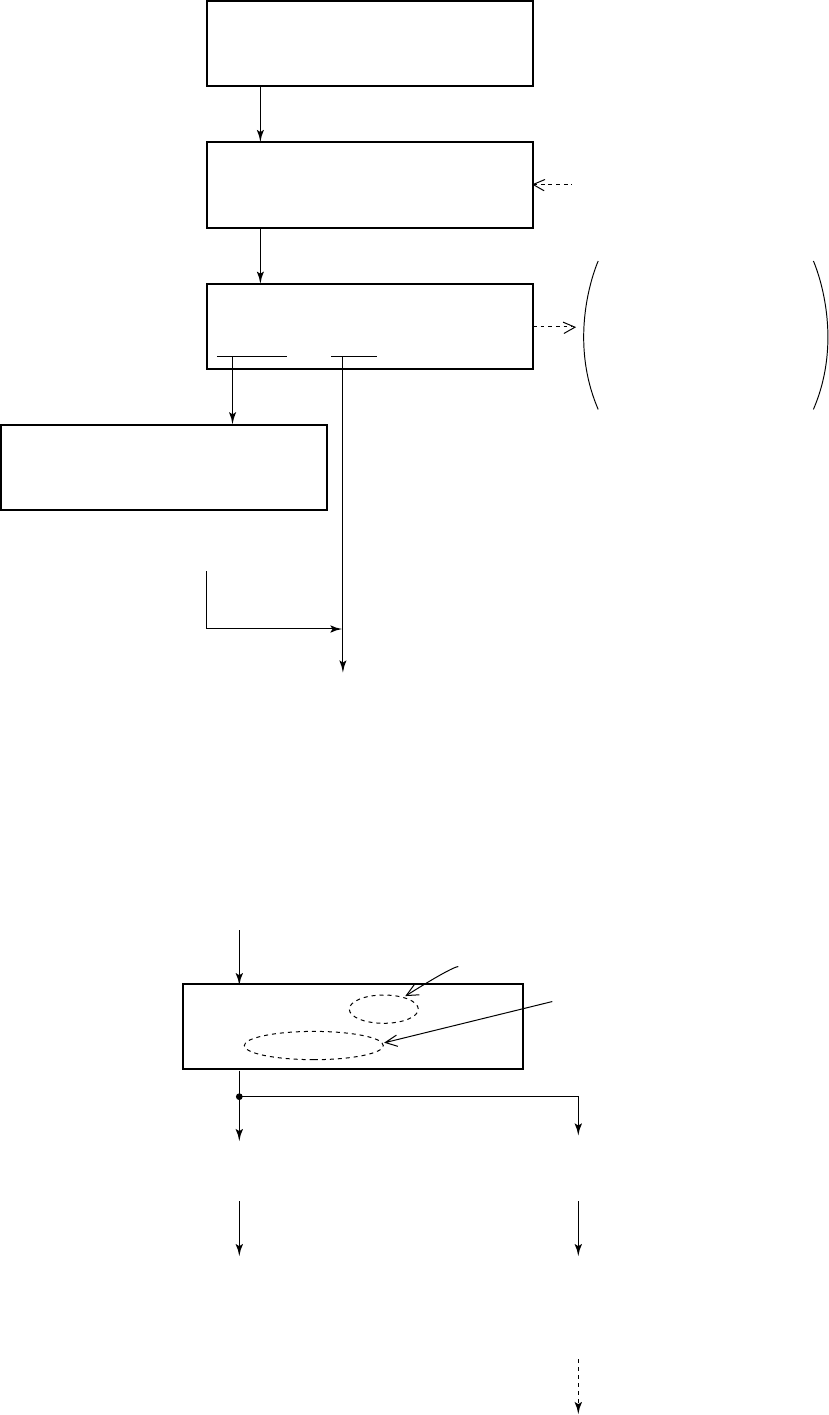
3.4 Distress Relay
General
If a vessel in distress is obviously near own ship and is not able to
transmit the distress alert by itself, you can relay (transmit) the
alert on behalf of the vessel in distress. You may relay a distress
alert in the following conditions;
1When the station in distress is not itself in a position to transmit
the distress message, or
2When the master or person responsible for the vessel not in dis-
tress, or the person responsible for the coast station, considers
that further help is necessary.
However, DO NOT press the [DISTRESS] key; it is for use when
own vessel is in distress.
Procedure
Watch VHF CH70
auto (Normal display)
To call specific coast station
(individual call), select “R/S”, then
press the [ENT] key. After that,
enter the coast station ID.
Relay/ALL
(All Ships Call)
Refer to page 5-1
for detail of items.
(Display for
All Ships Call)
(*1)
Press the [ENT] key.
Press the [ENT] key, and press the [SELECT] key.
(To select call type.)
Press the [ENT] key, and press the [SELECT] key.
(To enter ID of vessel in distress.)
(continued on next page)
Call type < >
IND TEL ALL R/A R/S DST
* VHF Call message *
Format: DIST RELAY ALL
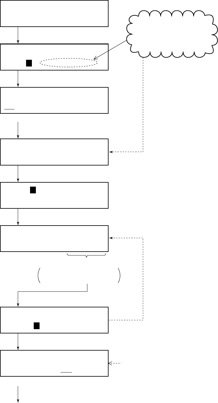
3-10
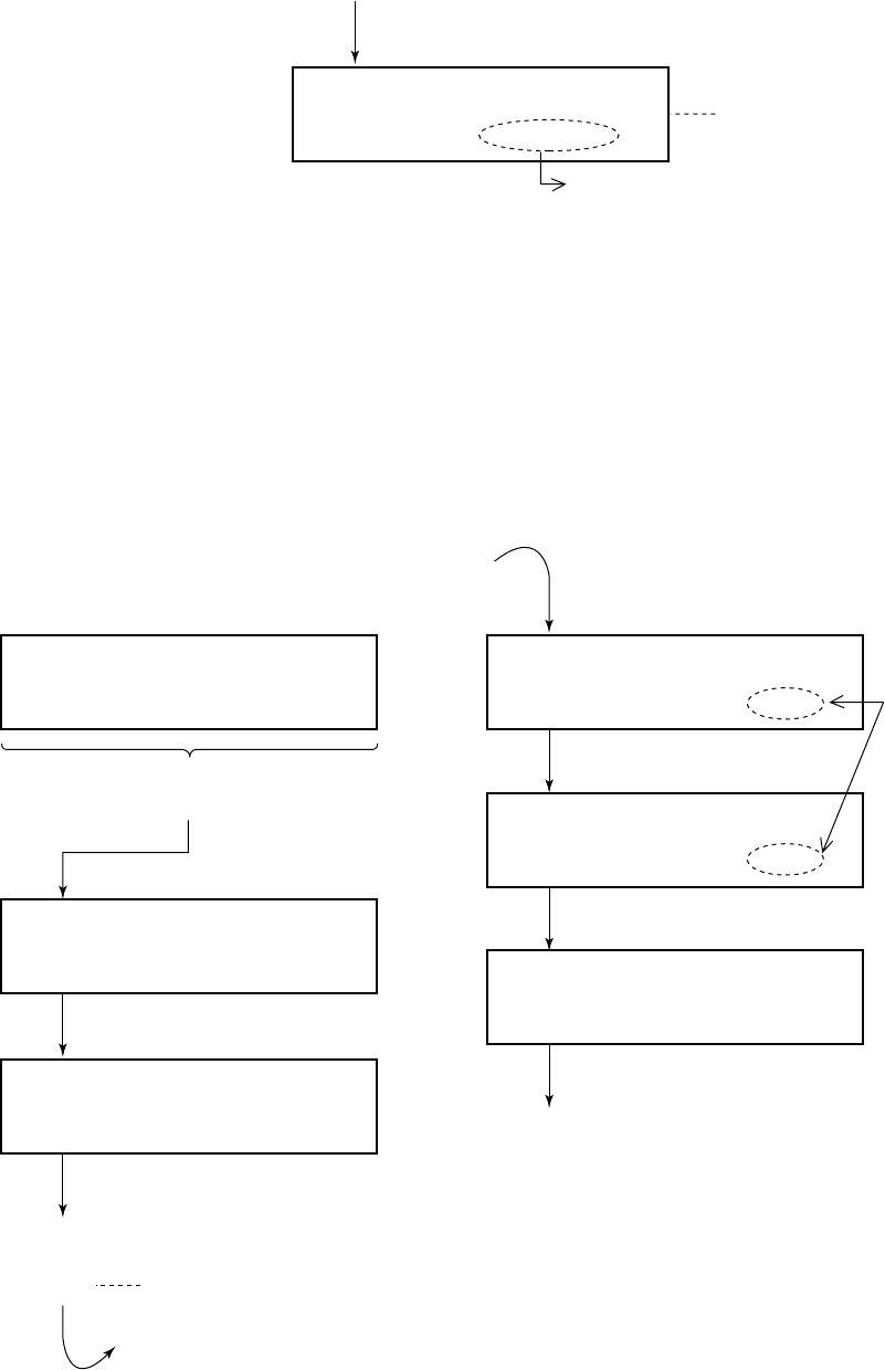
Nature of distress?
UNDESIGNATED DISTRESS
Position < >
NORTH=
* Ready for calling *
DIST RELAY ALL CH70
(from previous page)
To designate nature of distress,
press the [SELECT] key.
If unknown, press the [ENT] key, and press the
[SELECT] key.
(To enter position of vessel in distress.)
Press the [ENT] key, and press the [SELECT] key.
(To enter time.)
Manually enter position of vessel in distress, referring to page
3-4. If position is unknown enter "9999" (no information).
(continued on next page)
Distress UTC:
UTC?
Manually enter time.
(“9999” means no information.)
Press the [ENT] key twice.
Press the [CALL] key.
Press the [ENT] key.
Enter ID of vessel in distress.
(If not know, enter “99 …… 9” to set up for
“No information”.)
Address < No inform >
input DIGITS=
(*1)
3-11
DISTRESS RELAY ALL
Dist ship ID:
* No ack call received *
(from previous page)
(Distress ship ID
appears on second line.)
Returns to
normal display.
ID of vessel
in distress Counts down from
five minutes.
* Call in progress *
DISTRESS RELAY ALL
(Transmitting distress
relay to all ships/coast
station.)
Only for individual Call
(When selecting “R/S” in call type.)
Distress alert transmitted (relayed) for about 3 seconds.
* Wait for relay ack *
Dist: 4.8 min
If not acknowledged,
If acknowledged within
five min., press the
[ENT] key
successively to view
contents of receive
message from coast
station.
Press the [CANCEL] key to return to the normal display. Then,
relay distress call by all ships call, contact coast station, and
search and rescue vessel in distress.
After relaying the alert, you must conduct search and
rescue for the vessel in distress, following instructions
of a coast station.
“Wait for relay ack”
screen
Watch on CH16,
following instructions
of a coast station.
Watch on CH16,
following instructions
of a coast station.
For All Ships Call only
(When selecting "R/A" in call type.)
This page is intentionally left blank.
4-1
4. DSC Communication
4.1 Transmitting Individual Calls
General
The individual call is for sending message to a specific station.
After transmitting message (called ACK RQ transmission), wait to
receive the acknowledge back (ACK BQ) signal from receiving
station. You should receive it within five minutes.
Figure 4-1 Individual Call
General procedure
Load saved Tx message, or prepare
message.
Transmit message.
Receive ACK BQ from receiving station.
Communicate with station.
Own Ship Coast Station
2 Acknowledge back
(ACK BQ signal)
1 Individual call
(ACK RQ transmission)
4-2
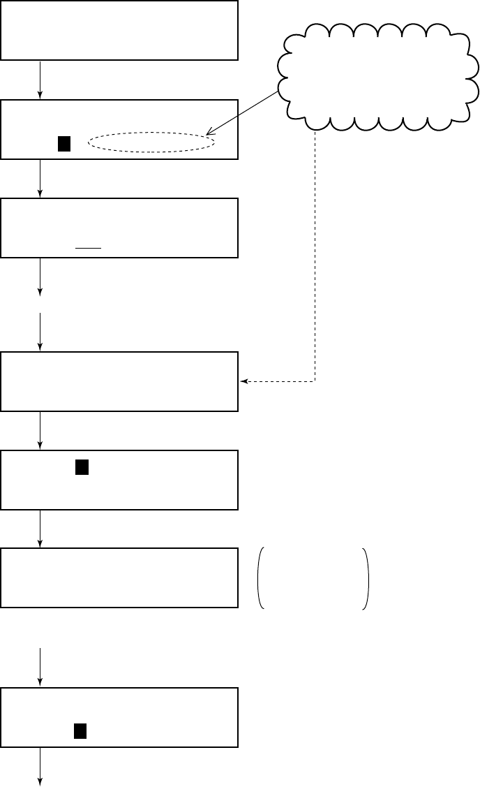
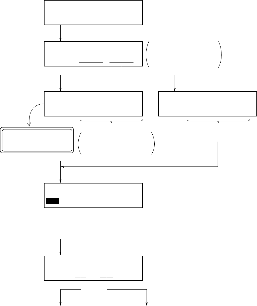
Detailed procedure
Prepare and transmit a message as follows.
Watch VHF CH70
* VHF call message *
Format?
Call type < >
IND TEL ALL ---
* VHF call message *
Format: INDIVIDUAL
Press the [ENT] key.
Press the [ENT] key.
Address?
Category:
Address < >
input digits =
Address:
Category?
Press the [ENT] key.
Press the [SELECT] key.
(To select format.)
Press the [SELECT] key.
(To enter other station ID.)
Press the [t] key.
(To return to
previous menu.)
Press the [SELECT] key.
(To select category.)
Press the [ENT] key.
Entry of other station ID
Ship station: 9 digits
Coast station: 00 + 7 digits
Place the cursor on “IND”.
(continued on next page)
Previously selected
format appears here. If
“INDIVIDUAL” appears,
press the [ENT] key.
Category < >
DIS URG SAF ROU
Select “ROU”.
“ROU” (Routine) is
normally selected.
Press the [ENT] key.
4-3
Telecom1?
Telecom2:
Telecom1 < >
SMP DUP DAT FAX NO
Press the [ENT] key.
Press the [SELECT] key.
(To select telecommand 1.)
Select mode desired.
Usually select “SMP” or “DUP”.
Address?
Category:
Address < >
input digits =
Address:
Category?
Press the [SELECT] key.
(To enter other station ID.)
Press the [t] key.
(To return to
previous menu.)
Press the [SELECT] key.
(To select category.)
Press the [ENT] key.
Entry of other station ID
Ship station: 9 digits
Coast station: 00 + 7 digits
Category < >
DIS URG SAF ROU
Select “ROU”.
“ROU” (Routine) is
normally selected.
4-4
(From previous page.)
After receiving the ACK BQ signal, do the following:
* Wait for ack BQ *
Next CH70
* Received * ACK BQ
ID: ROUTINE
Received station ID
ABLE: Receiving station
accepts working
channel proposed
by your ship.
UNABLE: "16" is displayed
when other ship
rejected working
channel proposed
by your ship. If
coast station was
called, however,
the LCD shows
"QUEUE INDI-
CATION,"
meaning the coast
station is busy.
Wait on channel
designated; the
coast station will
contact you.
When the ACK BQ signal is received;
1Alarm sounds. To silence, press the
[ALARM STOP] key.
2If ABLE appears, communicate with other
station over the VHF.
If UNABLE appears, prepare a message with
different proposal and transmit it by pressing the
[CALL] key. Repeat until proposal is mutually
accepted.
3If you want to view contents of receive
message, press the [ENT] key successively.
Returns to normal display.
4-5
4.2 Receiving Individual Call (ACK RQ)
General
When an individual call is received, the FM-8500 responds to the
call depending on the setting of automatic acknowledge (AUTO
ACK) function:
• AUTO ACK: ON (“auto” appears.)
The DSC transmits the acknowledge back (ACK BQ)
signal automatically.
• AUTO ACK: OFF (“manual” appears.)
Verify contents of receive message by pressing the
[ENT] key successively, then manually transmit the
ACK BQ signal by pressing the [CALL] key.
Figure 4-2 Receiving "Individual Call"
Setting of “ABLE” or “UNABLE”
When AUTO ACK function is ON, you can select either “able” or
“unable” (to comply) for proposal from other station. See the next
page.
Own Ship Coast Station
Individual call (ACK RQ)
4-6
Receiving individual call message (ACK RQ) with AUTO ACK On
The FM-8500 sends the ACK BQ signal automatically.
* Auto ack *
ID:
Automatic transmission of ACK BQ
(Alarm sounds.).
ABLE or UNABLE appears.
• When “able to comply” is
selected. (“ABLE” appears.)
Since the channel of the FM-8500
is automatically set to the channel
designated by a transmitting
station, voice communication can
be initiated by you or transmitting
station.
• When “unable to comply” is
selected. (“UNABLE” appears.)
The channel of the FM-8500 is
restored to the previous channel.
(The channel is diffrent from the
one designated by other station.)
Then, prepare a message with
diffrent proposal and transmit it by
pressing the [CALL] key.
Other station ID
Watch VHF CH70
Set up menu < >
1 2 3 ---
Comply status < >
UNABLE ABLE
ABLE: To accept
proposal of
transmitting
station.
UNABLE: Proposal is not
accepted.
Press the [SELECT] key.
(To diaplay Setup menu.)
Unable < >
NOR BSY ---
Press the [ENT] key.
Press the
[ENT] key.
Select reason why unable to comply.
(Normal setting: No reason)
Press the [ENT] key.
Setup menu
(Main menu)
Returns to normal display.
Normally set to ABLE.
4-7
Receiving ACK RQ with AUTO ACK Off
After verifying contents of receive message, manually transmit the
ACK BQ signal by pressing the [CALL] key within five minutes.
If the signal is transmitted more than five minutes after reception
of ACK RQ signal, it is treated as an ACK RQ signal rather than
ACK BQ.
* Received * ACK RQ
ID:
DUPLEX TP No information
Channel:
Acknowledge call < >
ACK END NEXT DEL
* Acknowledge call *
Telecom1? DUPLEX TP
Channel?
* Ready for calling *
ACK BQ CALL CH70
Press the [ENT] key.
Press the [ENT] key twice.
Press the [ENT] key.
Press the [ENT] key.
To transmit the ACK BQ signal, press
the [CALL] key.
Returns to normal display.
Then, communicate
with other station.
Communication mode
Confirm proposal
from other station.
Other ship ID
Alarm sounds. To silence, press the [ALRAM STOP] key.
(*1)
(continued on next page)
Communication mode
Working channel
• If no change is necessary,
press the [ENT] key. • To change working channel, press
the [SELECT] key then enter desired
channel number followed by the
[ENT] key.
To change communication
mode, press the [SELECT]
key.
Working channel
ACK: Transmits ACK BQ
signal.
END: Returns to normal
display.
NEXT: Recalls received
message.
DEL: Deletes received
message from
memory.
4-8
Telecom1 < >
UNA SMP DUP ---
Telecom unable comply?
No reason
Unable < >
NOR BYS ---
* Ready for calling *
ACK BQ CALL CH70
Working channel < >
input digits =
Channel?
Telecom1 < >
UNA SMP DUP ---
When changing communication mode.
Press the [ENT] key.
Press the [CALL] key.
Press the [ENT] key. Press the [ENT] key.
Select reason.
Press the [SELECT] key.
(To select reason why unable
to comply.)
Press the [SELECT] key.
(To change working channel.)
Press the [ENT] key.
Enter working channel.
If a diffrent communication mode is selected as shown
above, “ACK BQ” call is first transmitted and “ACK RQ”
call automatically continues.
This means the message proposed here is transmitted
as ACK RQ signal (not ACK BQ).
Finally the “Wait for ACK BQ” screen appears.
(*1)
(from previous page)
Example when selecting “Unable”.
(Proposal from transmittion station
is not acceptable.)
Example when
selecting “Simplex”.
4-9
4.3 Transmitting All Ships Calls
When to use All Ships Call
The All Ships Call is used to transmit important ship’s safety mes-
sage, safety of life at sea message or meteorological warning.
After transmitting message, you can communicate by voice over
the FM-8500.
Figure 4-3 All Ships Call
General procedure
The procedure for voice communication is shown on the next page.
Own Ship
Coast Station
Open file to transmit, or prepare message.
Press the [CALL] key.
Begin voice communications.
4-10
Detailed procedure
Watch VHF CH70
auto
* VHF call message *
Format?
Call type < >
IND TEL ALL ---
* VHF call message *
Format: ALL SHIPS
Press the [ENT] key.
Press the [ENT] key.
Category?
Telecom1:
Category < >
DIS URG SAF ROU
Press the [ENT] key.
Press the [ENT] key.
Press the [SELECT] key.
(To select format.)
Press the [SELECT] key.
(To select category.)
Select category desired.
(example: SAFety)
Place the cursor on “ALL”.
(continued on next page)
Previously selected
format appears here. If
“ALL SHIPS” appears,
press the [ENT] key.
Category: Safety
Telecom1?
Press the [SELECT] key.
(To select telecommand 1.)
DIS : Distress
URG : Urgency
SAF : Safety
ROU : Routine
Usually select priority higher than “SAF”.
4-11
Telecom1 < >
SMP DUP DAT ---
Telecom2: No information
Channel?
(from previous page)
Press the [ENT] key.
Press the [t] key.
(To return to
previous menu.)
Working channel < >
input digits = 16
* Ready for calling *
ALL SHIPS CALL CH70
* Call in progress *
ALL SHIPS CALL CH70
Press the [ENT] key.
To cancel message
prepared, press the
[CANCEL] key.
The channel of the
FM-8500 is
automatically set to
CH70 and the
message prepared
here is transmitted.
Returns to normal display.
Press the [SELECT] key.
(To enter working channel.)
Press the [CALL] key.
(To transmit call.)
Returns to nornmal display.
Since the channel of the FM-8500 is automatically
set to CH16 (designated above), you can commence
voice communication immediately.
Transmission time
about 0.5 seconds
Channel entry (example:16)
Select communication mode disired.
(example: Simplex)
Usually select “SMP”.

4-12
4.4 Receiving All Ships Calls
General
When an all ship’s call is received while conducting voice com-
munications, press [2] (AUTO ACK) to switch to VHF channel.
The all ship’s call, transmitted by coast station or ship station, pro-
vides navigation and weather alerts and emergency information.
Status of FM-8500
Procedure for on hook status
Basic procedure
tesdnaH sutats deviecersillacs'pihsllananehW
)*(koohnO
gnikrowotsehctiwsyllacitamotuatnempiuqE.1 .lennahc .draehebnaceciovs'rellaC.2
)*(koohffO
.sdnuosmralA.1 gnikrowothctiwsotyek)KCAOTUA(]2[sserP.2 .lennahc .draehebnaceciovs'rellaC.3
.koohnignuhtesdnaH:koohnO* .pudekciptesdnaH:koohffO
Watch DSC distress/safety channel.
Receive All Ships Call.
VHF channel is automatically selected.
Listen to message.
4-13
Detailed procedure
Procedure for off hook status
Basic procedure
Receive call < >
END NEXT DEL
Watch
auto
Select “END” and press the [ENT] key.
End
SIMPLEX NO INFORM
Channel: CH25
EOS: EOS ECC: OK
Press the [ENT] key.
Press the [ENT] key.
Watch VHF CH70
auto
* Received * ALL SHIPS CALL
ID: 007654321 Safety
Press the [ENT] key.
Below is the sequence for
receiving an All Ships Call in
auto acknowledge.
Channel is auto-
matically changed.
Listen to voice
message.
Notice of All Ships Call. arrives while communicating
with other ship.
Watch DSC CH70.
Receive All Ships Call.
Press the [2] key.
Press [ALARM STOP ] key to silence alarm.
Listen to voice message.
4-14
Detailed procedure
Below is the sequence for manually acknowledging an All Ships
Call when the handset is off hook.
Watch
manual
* Received * ALL SHIPS CALL
ID: 007654321 Safety
SIMPLEX NO INFORM
Channel: CH25
Press the [2 (AUTO ACK)] key followed by the [ENT] key to
change channel.
EOS: EOS ECC: OK
Press the [ENT] key.
Press the [ENT] key.
Do the following to receive an
ALL Ships Call.
Receive call < >
END NEXT DEL
Watch
manual
Select “END” and press the [ENT] key.
Listen to contents of message.
4-16
* Ready for filing *
Call message < >
01/59:
(from previous page)
Prepare a message by referring to
page 4-9 (All Ships) and page 4-1 (individual).
Press the [ENT] key.
(To select file number under which to save message.)
Name < >
END A B C D ------ R
Name < A1 >
END A B C D ---
Next file memory < >
END NEXT
Press the [ENT] key.
(To assign file name.)
* VHF call message M *
Format?
Press the [ENT] key.
Press the [ENT] key.
Returns to
normal display.
Press the [ENT] key.
To prepare another message;
To change specific character,
press the [SELECT] key and …
Assign a file name (max. 16 characters) by
the arrow keys, the [ENT] key and ten keys.
Press the [t] key to place the lower
cursor on “END”.
Example File Name: A1
1. Place the cursor on “A” with the arrow keys and press the [ENT] key.
(For alphabet always press the [ENT] key after selection.)
2. Press the [1] key.
File No.
(blinking)
To select a diffrent file
number, use the arrow
keys.
( :Up, :Down)
To scroll screen,
press the [s] key.
: Moves upper cursor
rightward every pressing.
: Moves upper cursor
leftward every pressing.
To change entire name,
press the [CANCEL] key.
Using the example above,
the unit saves the transmit
message to the memory
under file number 1, file
name “A1”.
4-17
4.6 Writing Over Files
General
You may write over unnecessary files. Simply prepare a message
and store it under file number of unnecessary file.
Procedure
Example: You want to write over file saved under file number 01.
Watch VHF CH70
* VHF call message M *
Format?
* Ready for filing *
Call message <New>
02/59:
Call message < >
01/59: A1
Name < A1 >
END ABCDEFG……
* Same file name exists *
Duplicate name? YES NO
Press the [SELECT] key, and press the [7] key,
and press the [ENT] key.
Press the [ENT] key.
If you don’t want to change file name,
press the [ENT] key.
Next file memory <End>
END NEXT
Press the [ENT] key.
(To wirte over existing file.)
Press the [ENT] key.
File name
Enter new name,
referring to
previous page.
Press the [t] key to display “01”.
Prepare a message (see page 4-1).
4-18
4.7 Retrieving, Transmitting Files
Retrieving a file
Transmitting a file
Watch VHF CH70
Call message < >
/59:
* Ready for calling *
Press the [7 (FILE)] key. / (Enter file no.)
/ Press the [ENT] key.
File name
To view contents of message, press the [ENT]
key successively.
• To transmit message: Press the [CALL] key
• To return to normal display: Press the [CANCEL] key.
(Normal display)
Watch VHF CH70
* Call in progress *
Press the [7 (FILE) ] key. / (Enter file no.)
/ Press the [CALL] key.
Returns to normal display.
(Normal display)
(Transmitting)
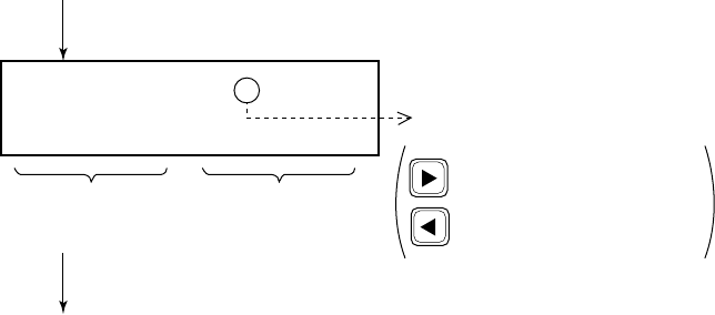
4-19
4.8 Transmit/Receive Message Memory
General
The transmit message memory stores up to 50 transmitted mes-
sages (numbered 1 to 50) on a first-in, first-out basis. This means
each time you save a transmitted message it is filed as log no. 1
and the log no. of all previously stored transmit messages changes
by one. When the memory is full the oldest file is deleted.
Retrieving a transmit message
Press the [9 (XMTD)] key at the normal display.
Xmitted log No. <1/50>
Log no. (page number)
Format
(Call type)
To view contents of message, press the
[ENT] key successively.
Time
transmitted
: Selects next log no.
: Selects previous log no.

4-20
Transmitting retrieved message
You can transmit a retrieved message as follows.
Xmitted log No. <1/50>
AD: Routine
DUP TP No infor
Channel:
EOS: ACK RQ
Press the [ENT] key.
Press the [ENT] key.
Call again < >
CALL END NEXT DEL
Channel?
* Ready for calling *
INDIVIDUAL CALL CH70
Press the [ENT] key.
Press the [ENT] key.
Press the [CALL] key.
Select “CALL”.
Press the [ENT] key.
To change working channel,
press the [SELECT] key.
[Example: Individual message is retrieved.]
Press the [t] key.
(To return to previous
menu.)
Select page by the arrow
keys.
END: Returns to normal
display.
NEXT: Recalls transmitted
message.
DEL: Deletes transmitted
message from
memory.
4-21
Receive message memory
All received messages are automatically saved to the memory and
filed according to category, DISTRESS or ORDINARY. The re-
ceive message memory can store up to 50 messages (numbered
1 to 50) of each category on a first-in, fist-out basis. This means
each time the unit receives a message it saves it as log no.1 and
changes the log no. of all previously received messages by one.
When the memory is full the oldest file is deleted.
Retrieving a receive message
Press the [8 (RCVD)] key at normal display.
Ordinary log No. <1/50>
Received call < >
DISTRESS ORDINARY
Log no. (page no.)
DISTRESS: Distress alert
received
ORDINARY: Other than
distress
Format (*1)
(Call type)
To view contents of message, press the
[ENT] key successively.
(*1): If own ship did not
transmit “ACK BQ”
(acknowledge back)
signal a blinking sharp
symbol (#) appears at
head of Format.
For example, “ORDINARY” log;
Press the [ENT] key.
Data received
: Selects next log no.
: Selects previous log no.
4-22
Transmitting retrieved message
You can send the acknowledged call (DIST ACK or ACK BQ)
under certain conditions after retrieving a received message. Refer
to page 3-5 for transmitting the DIST ACK signal.
Example: Transmit acknowledge back (ACK BQ) signal in response
to an individual call (Refer to page 4-5.)
NOTE: If the signal transmitted more than five minutes after re-
ception of ACK RQ signal, it is treated as an ACK RQ
signal rather than ACK BQ. Finally the “Wait for ACK
BQ” screen appears.
Acknowledge call < >
ACK END NEXT DEL
Received call < >
DISTRESS ORDINARY
Select “ORDINARY”, then press the [ENT] key.
* Acknolege call *
Telecom1?
Channel?
Press the [CALL] key to transmit the ACK BQ signal.
Press the [ENT] key.
Press the [ENT] key.
* Ready for calling *
ACK BQ CALL CH70
Press the [ENT] key.
Press the [t] key.
(To return to
previous menu.)
END: Returns to normal
display.
NEXT: Recalls received
message.
DEL: Deletes received
message from
memory.
Ordinary log No. <1/50>
To view contents of message,
press the [ENT] key successively.
Select “INDIVIDUAL”
number desired by the
arrow keys.
To change, press the
[SELECT] key.
To change, press the
[SELECT] key.

5-1
5. Other Calling Types and
Other Functions
5.1 Other Calling Types
General
The FM-8500 provides 12 calling types. Of these, individual, all
ships and distress were discussed in previous chapters. This sec-
tion describes the other types of calls available. The procedure for
preparing and transmitting other calls is the same as that for indi-
vidual and all ships calls: Select type of call, prepare message and
transmit it by pressing the [CALL] key.
Selection of calling type
Watch VHF CH70
* VHF call message *
Format?
Press the [ENT] key.
Press the [s] key.
(Normal display)
Call type < >
IND TEL ALL R/A R/S DIS
Call type < >
GRP GEO POS POL MED NEU
Press the [SELECT] key.
(To select calling type)
selectable
Description of all 12 calling types
appears on the next pages.
Calling
Type
To scroll screen,
place the cursor here and
press the [s] key.
5-2
• IND :Individual call (Refer to page 4-1.)
• TEL :Telephone call (semi-auto/auto call.
Refer to page 5-4.)
Call a terrestrial network, for example, your
office through a coast station.
• ALL :All ships call (Refer to page 4-9.)
• R/A and R/S :Distress relay for All ships and for Se-
lective (Individual) calls (Refer to
page 3-5.)
• DIS :Distress call (Refer to page 3-1.)
• GRP :Group call
Call a specific group by entering group ID
number.
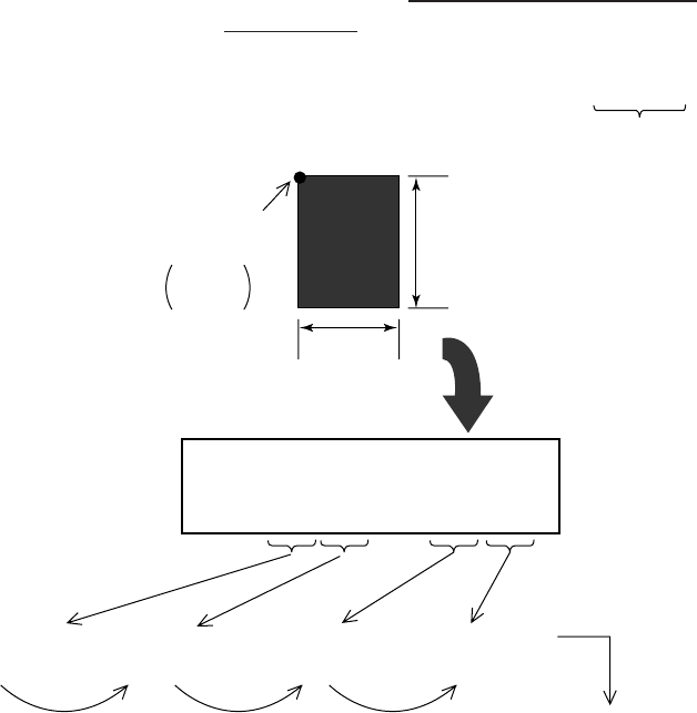
• GEO :Georgraphic area call
Call for ships within a range set by you in
the transmit message (menu). To designate
the range, enter reference point and width
(range) data of both longitude and latitude.
Example: Ocean AD … 34N 135E da10 do5
Range data
Reference
point
How to enter
the data.
Enter latitude
(34N).
Press the
[s] key. Press the
[s] key. Press the
[ENT] key.
Press the [s]
key twice.
Enter range
(da = 10). Enter longitude
(135E). Enter range
(do = 05).
5° = do
10° = da
135E 140E
34N
24N
34° N
135° E
Area < >
NORTH=00°-00° EAST=000°+00°
5-3
• POS :Position request individual call)
Find position of other ship by entering its
ID number.
• POL :Polling call (individual call)
Confirm that own ship is within communi-
cation range with other ship. This provides
only negative response; it does not provide
position information.
• MED :Medical transport (All ships call)
Inform all ships, by Urgency category,
that own ship carries medical goods.
• NEU :Neutral craft (All ships call)
Inform all ships, by Urgency or Safety
category, that own ship is not a participant
in an armed conflict.
5-4
5.2 Making Telephone Calls
When the coast station serves PSTN telephone service you can
make Telephone Call via Coast Station.
Basic procedure
1. Selection of Format specifier.
2. Entry of Coast Station ID.
3. Entry of Telephone number.
Detailed procedure
Watch VHF CH70
auto
Telephone number
DIGITS =
* Ready for calling *
PSTN CALL 001234567
Coast AD: 001234567
Tel No.?
Coast AD < >
7 DIGITS = 00………
Press the [ENT] key.
Press the [ENT] key.
Press the [ENT] key.
Press the [CALL] key to
transmit message.
(continued on next page)
Press the [2] key successively
until “auto” appears. Coast Station ID Entry
(example: 1234567)
Place the cursor on “TEL”.
Press the [ENT] key.
Press the [SELECT] key.
(To enter telephone number
(max. 16 digits)).
Telephone Number Entry
* VHF call message *
Format?
Format < >
IND TEL ALL ---
Press the [ENT] key.
* VHF call message *
Format? PSTN CALL
Press the [SELECT] key.
(To enter coast station ID.)
Coast AD?
Tel No.
Press the [SELECT] key.
Previously selected format
appears here.
5-5
PSTN CALL
* Waiting for ack BQ *
AUTO RETRY in 5 sec
(from previous page)
(Transmission time is about 0.4 - 0.6 seconds.)
(*)
(*)
Immediately
• If ACK BQ is received;
• If ACK BQ is not received;
Recall after 15 minutes.
If ACK BQ from coast station is not
received within five seconds PSTN
call is automatically retransmitted.
If ACK BQ is received, PSTN
CALL (EOS) signal and carrier are
transmitted (NOTE 1).
Working channel designated
by coast station.
Counts down.
* Call in progress *
PSTN CALL CH70
* Call in progress *
AUTO RETRY CH70
* Call in progress *
CARRIER
* PSTN CALL connected *
To end call: [CANCEL]
Transmission time is about
two seconds.
Ringer bell of VHF sounds. Take handset
from VHF hanger and commence voice
communication (see NOTE 2).
(NOTE 1) When you receive “unable to comply” (BUSY) command
instead of “able”, the FM-8500 waits for “Ring back call” from
coast station for 15.5 minutes. Then, if it is received, carrier
is automatically transmitted.
(NOTE 2) If there is no reply (voice response) from subscriber within
one minute at “PSTN CALL connected” display, the
communication line will be disconnected. The display should
look something like the display 2 on the page 5-7.
If you hang the handset on the hanger, the display 1 shown
on the next page appears to break the communication line.
* Waiting for ack BQ *
5 sec to go
* No response *
Try again after 15 min
Counts down.
5-6
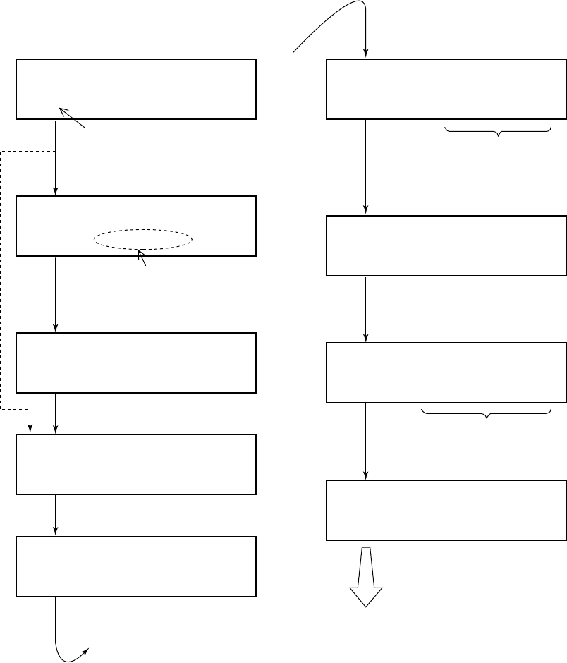
Operation after making DSC call
Voice communication is started. After completion of communica-
tion, the display changes as shown in (1) or (2) below depending
on how voice communication terminated.
(1) When you end voice communication by pressing the [CAN-
CEL] key or hanging the handset on the hanger of the VHF, the
display of the FM-8500 changes as follows.
PSTN CALL
Transmits “End of call” command.
Display 1
Working channel
* Call in progress *
END OF CALL
• If “End call ack” is not received
within two seconds; • If “End call ack” is
received;
* Waiting for end call ack *
AUTO RELAY in 2 sec
* Call in progress *
AUTO RETRY
* End call not received *
No charge information
* Waiting for end call ack *
2 sec to go
Counts down.
• If not received;
(No charge time information)
* Received * END OF CALL
Charge time:
Charge time appears.
• If “End call ack” is receiver;
5-7
(2) When coast station terminates communication, the display of
the FM-8500 is as follows.
NOTE: If a subscriber hangs the handset on the hanger to termi-
nate voice communication, coast station will transmit the
“End of call” command to you to break the communica-
tion line.
5.3 Receiving Telephone Call from Coast Station
When the “End of call” command from
coast station is received;
Display 2
* Received * END OF CALL
Charge time:
Charge time
appears
* Call in progress *
PSTN CALL Working
channel
Watch
auto
* Call in progress *
PSTN CALL ACK CH70
* Call in progress *
CARRIER
* PSTN CALL connected *
To end call: [CANCEL]
Tramsmits PSTN CALL (EOS)
signal and carrier.
Reply signal is automatically
transmitted after reception.
Alarm of FM-8500 sounds. Take the
handset from VHF hanger within 60
seconds. NOTE 1
Commence VHF communication. After
completion of communication, the display
changes as shown above: Display 1 or
Display 2.
NOTE 1: If more than 60 seconds elapses
without taking the handset from
the hanger, call is canceled.
* Auto ack * ABLE PSTN CALL
Pick up the handset!
5-8
5.4 Other Station IDs and Telephone Nos.
Registering
You can program often-used station IDs and telephone numbers
under a file name.
Watch VHF CH70
File < >
MESSAGE ADDRESS TEL No.
Name < >
END A B C D ---
Next file memory < >
END NEXT
Address number < >
9 DIGITS=
Press the [SELECT] key, and
press the [7] key.
Assign file name by following the
procedure shown on page 4-16. After
assigning file name, place the cursor
on “END” then press the [ENT] key.
Press the [ENT] key.
Press the [ENT] key.
Returns to normal display. Returns to screen for entry of
other station ID or telephone
number.
Press the [ENT] key.
Press the [ENT] key three times.
Enter number.
Ship Station: 9 digits
Coast Station: 00 + 7 digits
Group Call: 0 + 8 digits
You can receive group
calls having group ID
numbers registered here.
Address: Other Station ID
(max. 99)
Tel No. : Telephone No.
(max. 50)
Telephone number < >
DIGITS=
Press the [ENT] key.
Enter telephone number.
(max. 16 digits)
5-9
Address?
Address file < >
Coast AD Ship AD
Coast AD < >
01/99:
Select desired ID number (file
number) with the arrow keys.
Press the [ENT] key.
Press the [7] key.
Press the [ENT] key. Press the [ENT] key.
Select one. (Example: Coast AD)
ID number selected is input into the
transmit message.
Press the [SELECT] key at display 1.
Press the [SELECT] key. / (Numeric order)
Note: Each press of the [SELECT] key at display 1 or display 2 alternates file number
and alphabet prefixed file name.
Telephone number selected is input
into the transmit message.
[Example]
1. Retrieving Other Station ID
Individual Call
Blinking
File No.
File Name
Channel:
Tel No.?
Tel < >
01/50
A1/ZZ:
Press the [7] key.
Select desired telephone file
number with the arrow keys.
2. Retrieving Telephone Number
Telephone Call
Blinking
Display 1
(Alphabetical order)
Display 2
Retrieving
You can retrieve a file registered on previous page, and use it with
message which you are currently preparing.
To retrieve a file, press the [7 (FILE) ] key on a display where
the blinking question mark appears.
This page is intentionally left blank.

6-1
6. Other Settings
6.1 Printer Setup (Auto/Manual)
You can select either automatic or manual printing by following
the procedure shown below. (Factory setting: Auto)
Procedure
Automatic printing
With connection of the optional printer and “AUTO” is selected as
above, all transmitted and received messages will be automatically
printed out when transmitted and received.
Watch VHF CH70
Set up menu < >
1 2 3 ---
Press the [SELECT] key.
(Normal display)
Press the [4] key.
(To select Print out menu.)
Print out < >
AUTO/MANU EEPROM
Press the [ENT] key after
selecting “AUTO/MANU”.
Setup menu (Main menu)
Print out < >
AUTO MANU
Select either one.
Press the [ENT] key.
Returns to normal display.
AUTO: Automatic printing
MANU: Manual printing
6-2
Manual printing
When “Manual” is selected, press the [4 (PRINT)] key to print out
message desired. Note that manual printing is available even when
“AUTO” is selected.
The contents to be printed depend on when the [4] key is pressed,
as shown in the table below.
No. Example
Pringout
a1
Printing Timing of [4] key pressing
Contents of {VHF call message} During “VHF call message” display to “Ready
for calling ” display
b2Contents of all transmitted logs
{Xmitted log No. < >} Displayed [Xmitted log No. < >]
(To stop printing, press the [CANCEL] key.
c3Contents of specific log no. (for example,
log no. 1)
{Xmitted log No. <1/50>}
During “[Xmitted…] e Press the [ENT] key.”
display to “EOS” display.
d5Contents of all received logs {Ordinary log
No. < >} Displayed [Ordinary log No. < >]
(To stop printing, press the [CANCEL] key.)
g8Contents of currently prepared
{VHF call message M} During “VHF call message M” display to
“Ready for filing ” diaplay.
h9All lists of {saved message} or contents of
all {Address or Tel No.} files.
• Press the [SELECT] key. e
Press the [7] key.
• For example, to print out all coast addresses
in the memory, press the [4] key at display 1
on page 5-9.
a4Call message (again)
Press the [ENT] key.
Press the [ENT] key.
to
to
Press the [4] key to print out all list of
saved messages.
Press the [ENT] key.
While these
displays
appears
e
f
6Contents of specific log no. (for example,
log no. 1)
{Ordinary log No. <1/50>}
71 Currently received message
2 Acknowledge message “Ready for calling” is displayed.
[Ordinary… ] display e Press the [ENT] key.
Call again
CALL END…
Channel?
Ready for calling
File < >
Message Address Tel No.
* Received * While these
displays
appears
(Distress)
(Distress)
(Distress)
* Received * ECC: OK
Acknowledge call < >

6-3
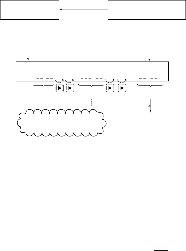
Example printout
Format
Address
Category
Telecom1
Telecom2
Channel
EOS
ECC
DSC ch
: INDIVIDUAL
: 000000000
: Routine
: DUPLEX TP
: RES No.18
: 23
: ACK RQ
: ……
: 70
Format
Address
Category
Telecom1
Telecom2
Channel
EOS
DSC ch
: INDIVIDUAL
: 004310000
: Routine
: DUPLEX TP
: RES No.18
: 23
: ACK RQ
: 70
a
Format
Address
Category
Telecom1
Telecom2
Channel
EOS
ECC
DSC ch
: INDIVIDUAL
: 000000000
: Routine
: DUPLEX TP
: RES No.18
: 23
: ACK RQ
: OK
: 70
g
Xmt message 00:09
Format
Address
Category
Telecom1
Telecom2
Channel
EOS
ECC
DSC ch
: INDIVIDUAL
: 004310000
: Safety
: SIMLEX TP
: RES No.18
: No information
: ACK RQ
: OK
: 70
Xmt message 02:03
c
Format
Address
Category
Telecom1
Telecom2
Channel
EOS
DSC ch
: INDIVIDUAL
: 004310000
: Routine
: DUPLEX TP
: RES No.18
: 23
: ACK BQ
: 70
***** Xmitted log *****
Xmt message 12:34
b
Format
Category
Telecom1
Telecom2
Channel
EOS
ECC
DSC ch
: ALL SHIPS
: Safety
: SIMPLEX TP
: RES No.18
: 16
: EOS
: OK
: 70
***** Ordinary log *****
Rcv message 02:04
d
Format
Address
Category
Telecom1
Telecom2
Channel
EOS
ECC
DSC ch
: INDIVIDUAL
: 431000001
: Routine
: DUPLEX TP
: RES No.18
: 23
: ACK RQ
: OK
: 70
Rcv message 00:07
e
01: FURUNO Individual
02: CAPTAIN All ships
**** Call message file ****
e
Format
Address
Category
Telecom1
Telecom2
Channel
EOS
DSC ch
: INDIVIDUAL
: 431000001
: Routine
: DUPLEX TP
: RES No.18
: 23
: ACK BQ
: 70
f
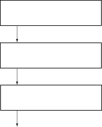
6-4
6.2 Turning Keyboard Click ON/OFF
You can turn keyboard click (response) on or off as follows:
Press the [SELECT] key.
Watch VHF CH70
auto
Press the [6] key.
Set up menu < >
1 2 3 4 6 7 9 ALM
Select ON or OFF and press
the [ENT] key.
Normal display appears.
Keyboard click < >
ON OFF
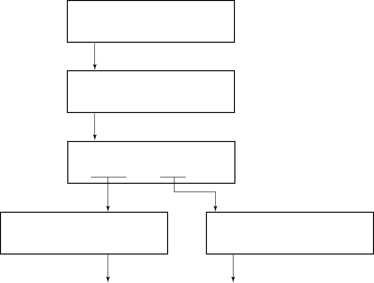
6-5
Alarm
ON/OFF TYPE
Press the [SELECT] key.
Watch VHF CH70
auto
Press the [ALARM STOP] key and then
press the [ENT] key.
To turn the aural on or off, select
ON/OFF. To select alarm tone,
select TYPE.
Set up menu < >
1 2 3 4 6 7 9 ALM
Press the [ENT] key. Press the [ENT] key.
Normal display appears. Normal display appears.
Select ON or OFF and
press the [ENT] key.
Ordinary alarm < >
ON OFF
Select desired alarm tone and
press the [ENT] key.
Distress alarm type < >
1 2 3 4 5 6 7 8 9
6.3 Aural Alarm Setup
The aural alarm which sounds when messages other than distress
and urgency are received may be turned on or off and the distress
alarm tone may be selected.
Procedure
This page is intentionally left blank.
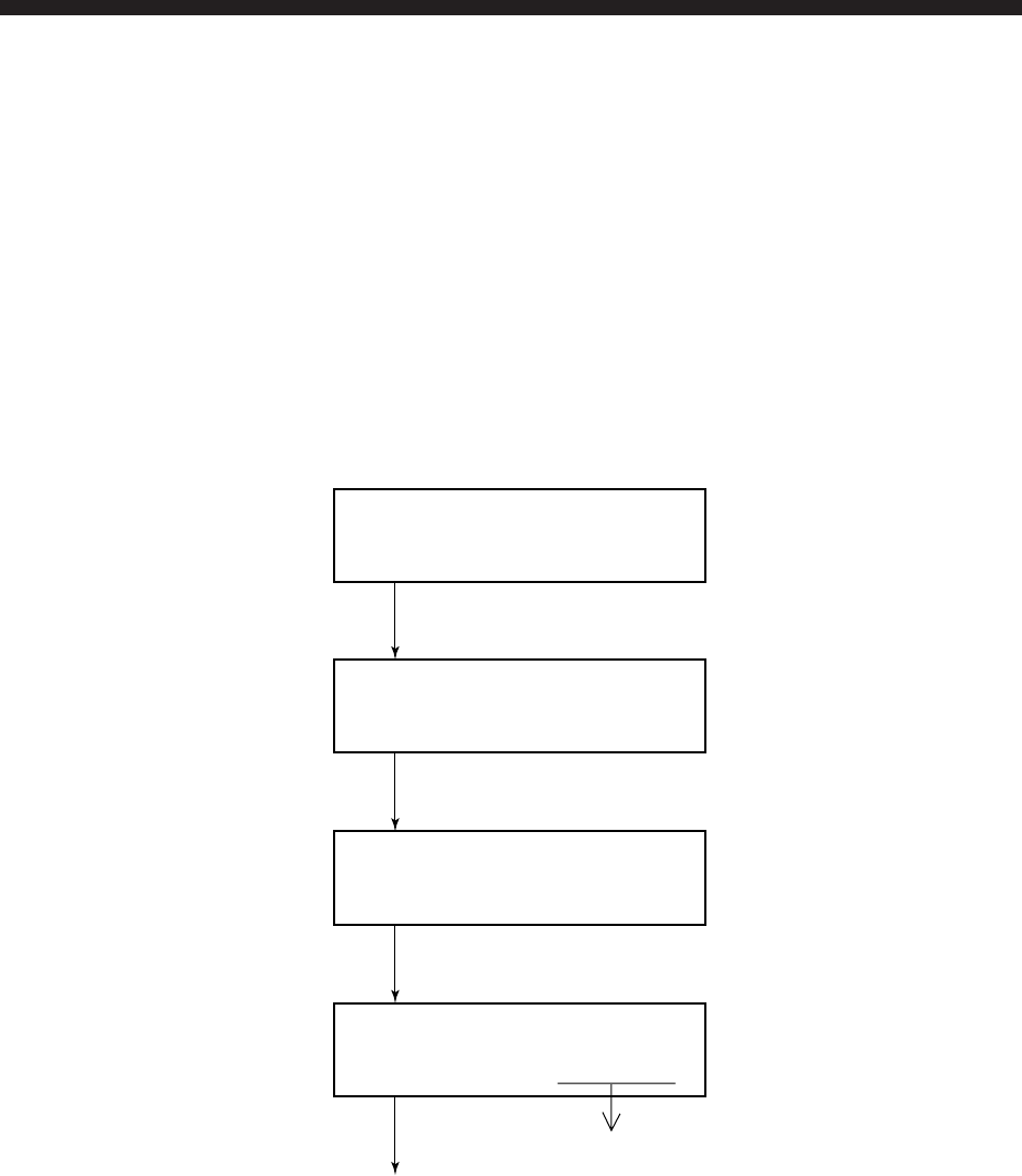
7-1
7. System Confirmation
Overview
This chapter shows how to confirm the system; no items can be
changed.
7.1 Confirming Own Ship’s ID
Own Ship’s ID can be confirmed as follows:
Procedure
Press the [SELECT] key.
Press the [9] key, or the [s] key seven times and the [ENT] key.
Select “ID” and press the [ENT] key.
To escape, press the [CANCEL] key three times.
Own ship’s ID
Screen 1
Set up menu
1 2 3 4 6 7 9 ALM
System < >
V P ID DSC RT CH PO
* Own indentificaion No. *
protected MMSI: 123456789
Watch VHF CH70
auto

7-2
7.2 Confirming ROM Version
You can see ROM Version (as registered in the memory) as fol-
lows:
Procedure
At screen 1 previous page, select “V” and press the [ENT] key.
To escape, press the [CANCEL] key three times.
RT is the VHF section’s ROM version.
DSC is the section’s ROM version.
ROM version
RT:1.06 DSC:1.10
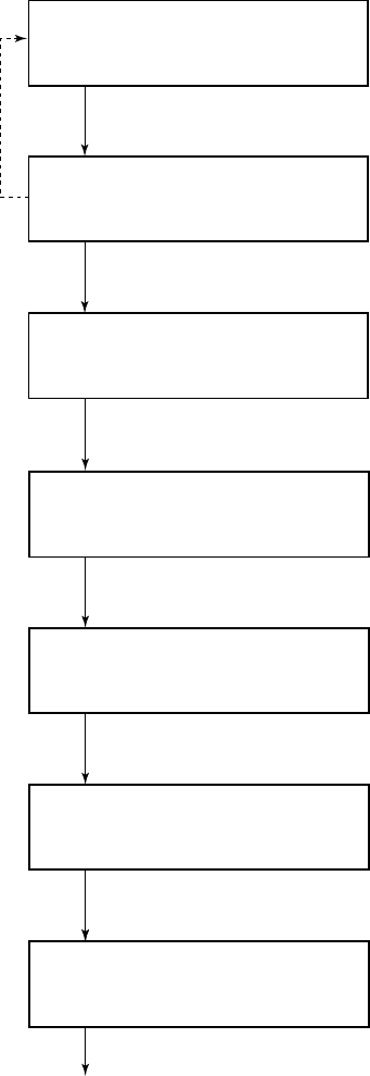
7-3
7.3 Confirming VHF Section Settings
You can confirm VHF section settings as follows:
If you want to change VHF section settings, contact FURUNO
agent or dealer for service.
Procedure
At screen 1 on page 7-1, select “RT” and press the [ENT] key.
Press the [ENT] key.
Press the [CANCEL] key
to go to previous display.
Press the [ENT] key.
Press the [ENT] key.
Time-out timer status (ON/
OFF) appears.
Select USA/PRIV mode in the
VHF channel mode.
In on-hook status, CH16 and
speaker status appear.
RT 2-Hookworking: CH16 SP
protected ON ON
RT 3-Time out timer: off
protected
RT 1-Mode: USA/WX PRIV
protected ON OFF
Press the [ENT] key.
Press the [ENT] key.
Press the [ENT] key.
To escape, press the [ENT] key and then press the [CANCEL]
key twice or to see VHF channels, press the [ENT] key twice.
Dual watch and scanning
status is displayed.
Auto squelch status is
shown.
ON: Monitor Tx AF signal
from RB-700, Wing HS, HS
and DSC.
Automatic TX power
reduction status (ON/
OFF) appears.
RT 5-Auto 1W: ON
protected
RT 6-Scanning: DW SCAN
protected OFF OFF
RT 7-AutoSQ: LOW HIGH HOLD
protected
RT 4-Tx AF monitor: OFF
protected
00 03 30
CH16: ON>Automatically switches to CH16
when handset is on hook.
SP: ON>Handset is off hook: SP is OFF.
Handset is on hook: SP is ON.

7-4
Press the [CANNEL] key to select channel mode.
Rotate the [CHANNEL] key control to view channels.
Do one of the following:
Continue channel confirmation: Operate the [CHANNEL] key.
Escape: Press the [CANCEL] key.
Confirm Tx power: Press the [ENT] key twice.
USA CH: 16-Tx SIMP LOW
protected sel[MODE]/[CH]
USA CH: 16-Tx SIMP LOW
protected sel[MODE]/[CH]
INTL CH: 016-Tx SIMP HI
protected sel[MODE]/[CH]
7.4 Confirming VHF Channels
You can confirm VHF channels registered as follows:
Procedure
At screen 1, select “CH” and press the [ENT] key.
VHF channel status
xR/xT:xTPMIS
)xelpmiS(
IH
)W52(
ylnoxR:xRPUD
)xelpuD(
WOL
)W1(
desutonlennahC:elbanU
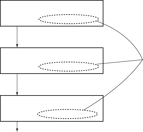
7-5
Press the [HI/LOW] key
to see low Tx output power.
To view other channel modes,
press the [CHANNEL] key.
To escape, press the [CANCEL] key three times. The normal display
appears.
Tx output power settings
on private channels can be
confirmed by rotating the
[CHANNEL] key.
Appears when private
channels are registered.
Tx power: CH60 CH14 CH88
Protected
Tx power: Priv01/CH123
Protected HI:753 LOW:108
Tx power: CH60 CH40 CH88
Protected 753 748 747
103 105 103
Power settings
7.5 Confirming Tx Output Power
The Tx output power on three VHF bands (low, CH60; med, CH14,
high, CH88) can be confirmed as shown below. Tx output power
on private mode channels can also be confirmed if applicable.
Procedure
At screen 1 on page 7-1, select “PO” and press the [ENT] key.
To escape, press the [CANCEL] key three times. The normal dis-
play appears.
This page is intentionally left blank.
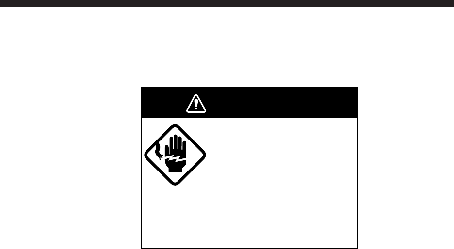
8-1
8. Maintenance & Troubleshooting
8.1 Maintenance
Do not work inside the
equipment unless totally
familiar with electrical
circuits.
Hazardous voltage which can
cause electrical shock, burn or
serious injury exists inside the
equipment.
WARNING
Antenna connectors
1. Check that each connector is firmly connected.
2. Clean corroded or soiled connectors.
3. Check coaxial cable for damage. If damaged, replace.
4. Check that bolts fixing the antenna are firmly tightened.
8.2 Troubleshooting
When the power cannot be turned on
1. Check if power plug is firmly connected.
2. Check breaker at the rear of the equipment. If it has tripped,
push it in to reset.
3. If power cannot be turned on, contact a FURUNO agent or rep-
resentative.
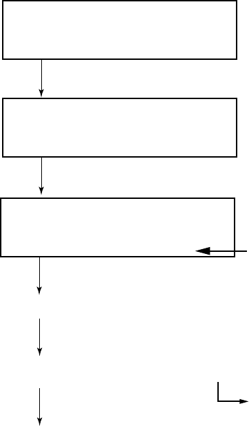
8-2
8.3 Diagnostic Test
Regulations require that the DSC section be checked daily for proper
operation.
Procedure
Select a channel not in use and press and hold down the PTT switch
of the handset for more than one second before starting self test.
Watch VHF CH70
auto
Press the [3 (TEST)] key.
* Text in progress *
please wait!
Several seconds later
(continued on next page)
* Completed * Daily test
VHF DSC: GOOD
Normal display
Appears during testing
End diagnostic test
Distress alarm sounds and red LED near the [DISTRESS] key lights.
Press [ALARM STOP] to silence the aural alarm.
For "GOOD', press [CANCEL] key
to return to the normal dispay.
For "NG" (No Good), press the [ENT] key to find reason for NG.
When you didn't press the PTT switch
before diagnostic test, "except VSWR"
is displayed.
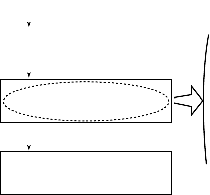
8-3
(from previous page)
Press [ENT] to view results of test.
Press the [t] key. To escape, press the [CANCEL] key.
If NG appears, have a technician replace corresponding p.c. board.
Check end: [CANCEL] key
TRANSMIT POWER : NG
= P.A. of transmission section
error or Antenna
TX PCB(PLL LOCK) : NG
= PLL(U5) error on the Tx PCB
CONTROL PCB : NG
= MODEM(U29) error on the Control PCB
or
CH70 Rx PCB: NG
= VHF RX/CH70 RX PCB error
NOTE:Do not open the equipment at any time. Electrical shock hazard exists
inside the equipment. Contact FURUNO agent or dealer for service.
This page is intentionally left blank.

9-1
9. Specifications
General
Channel Programs: INTL Channel: 55
USA Channel: 55
WX Channel: 10
PRIV Channel: 20 (authorization required)
Oscillator: PLL synthesizer
Communication System: Semi-duplex & Simplex
Class of Emission: G3E, G2B
Antenna Impedance: 50 Ω
Dimensions and Mass: 258 (W) X 108 (H) X 230 (D) mm, 5kg
Temperature: -20˚C to 55˚C
Relative Humidity: 93% at +40˚C;
Waterproofing: Panel: IEC529 IPX4
Chassis: IEC529 IPX2
Power Supply: 24 VDC -10% ~ +30%
Transmit: 150 W
Receive: 10 W
Color: Panel: Munsell N3.0
Chassis: Munsell 2.5GY 5/1.5
Transmitter
Frequency Range: 155.00 to 161.475 MHz
RF Output Power: 25W (HI), 1W (LOW)
Modulation AF Response: Within +1/-3 of 6dB/oct pre-emphasis characteristics at
300 to 3000 Hz
Frequency Deviation: ±5 kHz max.
Spurious Emission: Less than 0.25 µW
Modulation System: Reactance Type
9-2
Receiver
Frequency Range: 155.000 to 166.075 MHz
Receiving System: Double-Conversion Superheterodyne
Intermediate Frequency: First IF: 21.4 MHz
Second IF: 455 kHz
Sensitivity: -8dBmV at SINAD 12 dB
Adjacent Channel Selectivity: 70 dB min.
Spurious Response Rejection: 70 dB min.
Audio Output: Internal Speaker:3W min. (8ohms)
Handset: 2mW min. (200ohms)
DSC Section
Protocol: Complies with ITU-R Rec. M.493-9 (ClassA), M.541-8
and M.689-2
Modulation Rate: 1200 baud –30 p.p.m. max.
Modulation: AFSK
Modulation Frequency: Mark: 1300 Hz –10 Hz max.
Spece: 2100 Hz –10 Hz max.
Nav. Equipment Interface: IEC61162-1 (NMEA0183 Ver. 2.00)
CH70 Receiver Sensitivity: Symbol Error Rate 10-2, input -3dBmV
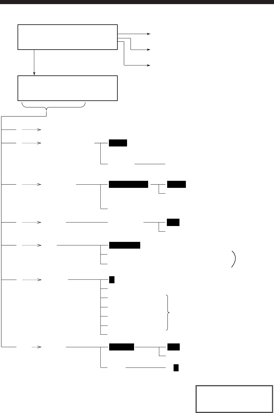
10-1
10. Menu List
Watch VHF CH70
Press the [SELECT] key.
(Set up menu)
Set Up menu < >
1 2 3 --- ALM
Press the [ENT] key.
Press the [8 (RCVD)] key.
Press the [9 (XMTD)] key.
(p. 10-2)
(p. 10-3)
(p. 10-3)
(Latitude/Longitude/UTC)
UNABLE NOR/BSY/DSA/CH/MOD
(Reason why unable to comply)
MENU (Manual printing)
1
COMPLY STATUS
(Proposal from
other station is
acceptable or not.)
PRINT OUT
2
4
ABLE
AUTO/MENU AUTO
SOUND
6KEY-CLICK ON
(Automatic printing)
(Storing message. Max. 59)
OFF
FILE
7MESSAGE
ADDRESS (Storing other station ID. Max. 99)
TEL No. (Storing telephone number. Max. 50)
EEPROM (Contens of EEPROM)
SYSTEM
9
ON
OFF
DSC
RT
CH
TYPE 0/ 1 /2…/9 (Distress and urgent
alarm tones)
(Confirmation of ROM version number)
P (Protection of data)
ID (Own ship ID)
ALARM
(Receive alarm)
ALM ON/OFF
Threse settings can not
be changed once
registered by Installing
technician.
PO
V
(p. 3-4)
(p. 4-5)
(p. 6-1)
(p. 6-4)
(p. 4-15)
(p. 5-8)
(p. 7-1)
(p. 6-5)
Default settings shown
in highlight.

10-2
Press the [ENT] key.
(Preparing transmit message)
* VHF Call mesage *
Format ?
• Normal display
FORMAT
INDIVIDUAL ADDRESS CATEGORY TELECOM WORKING CH
TELEPHONE
(DIALPHONE) COAST ADDR TEL NO.
ALL SHIPS CATEGORY TELECOM WORKING CH
R/A (DISTRESS RELAY…ALL SHIPS) DIST SHIP ID N. OF DIST POS & TIME
R/S (DISTRESS RELAY…INDIVIDUAL) COAST ADDR
DISTRESS NATURE OF DISTRESS POSITION & TIME
GROUP GROUP ADDR CATEGORY TELECOM WORKING CH
GEOGRAPHIC AREA
OCEAN ADDR CATEGORY TELECOM WORKING CH
POSITION REQUEST ADDR CATEGORY
(Normally ROUTINE)
TELECOM
(POSITON)
POLLING ADDR CATEGORY
(Normally ROUTINE)
TELECOM
(POLLING)
MEDICAL TRANSPORT TELECOM WORKING CH
NEURAL CRAFT CATEGORY WORKING CH
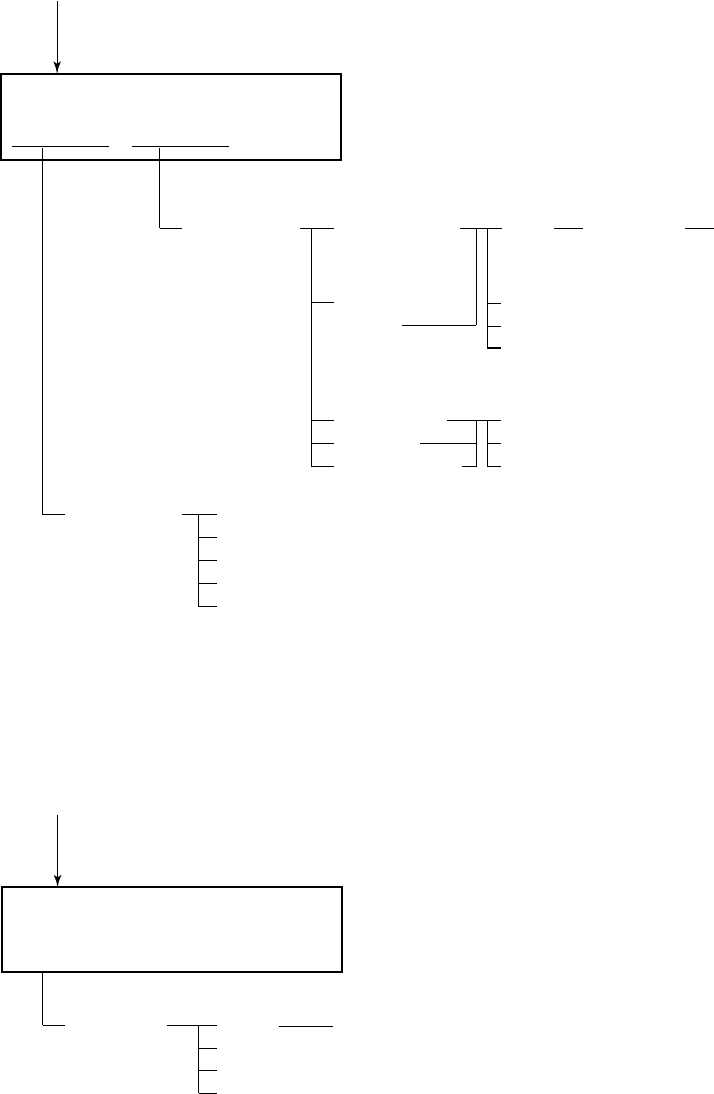
10-3
Press the [8 (RCVD)] key.
(Viewing contents of receive message)
Received call < >
DISTRESS ORDINARY
• Normal display
ORDINARY
LOG No.
(1 - 50)
INDIVIDUAL
DISTRESS
LOG No.
(1 - 50)
DIST ACK
RELAY
END
NEXT
DEL
ACK
SEMI-AUTO/
AUTO
(DIALPHONE)
ACK
NEXT
DEL
ALL SHIPS
GROUP
GEOGRAPH
END
NEXT
DEL
TELECOM WORKING CH
Press the [9 (XMTD)] key.
(Viewing contents of transmit message)
Xmitted log No. < >
• Normal display
XMITTED
LOG No.
(1 - 50)
CALL WORKING CH
END
NEXT
DEL
This page is intentionally left blank.
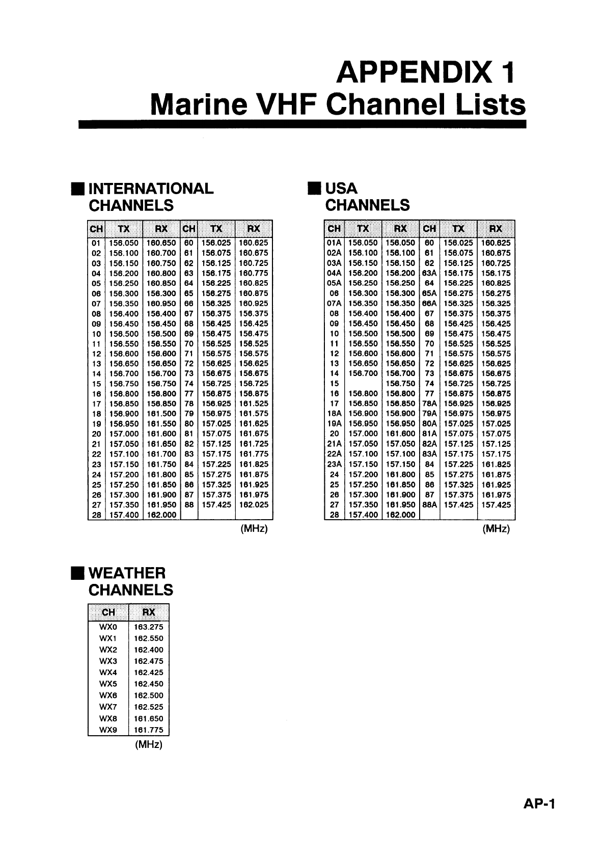
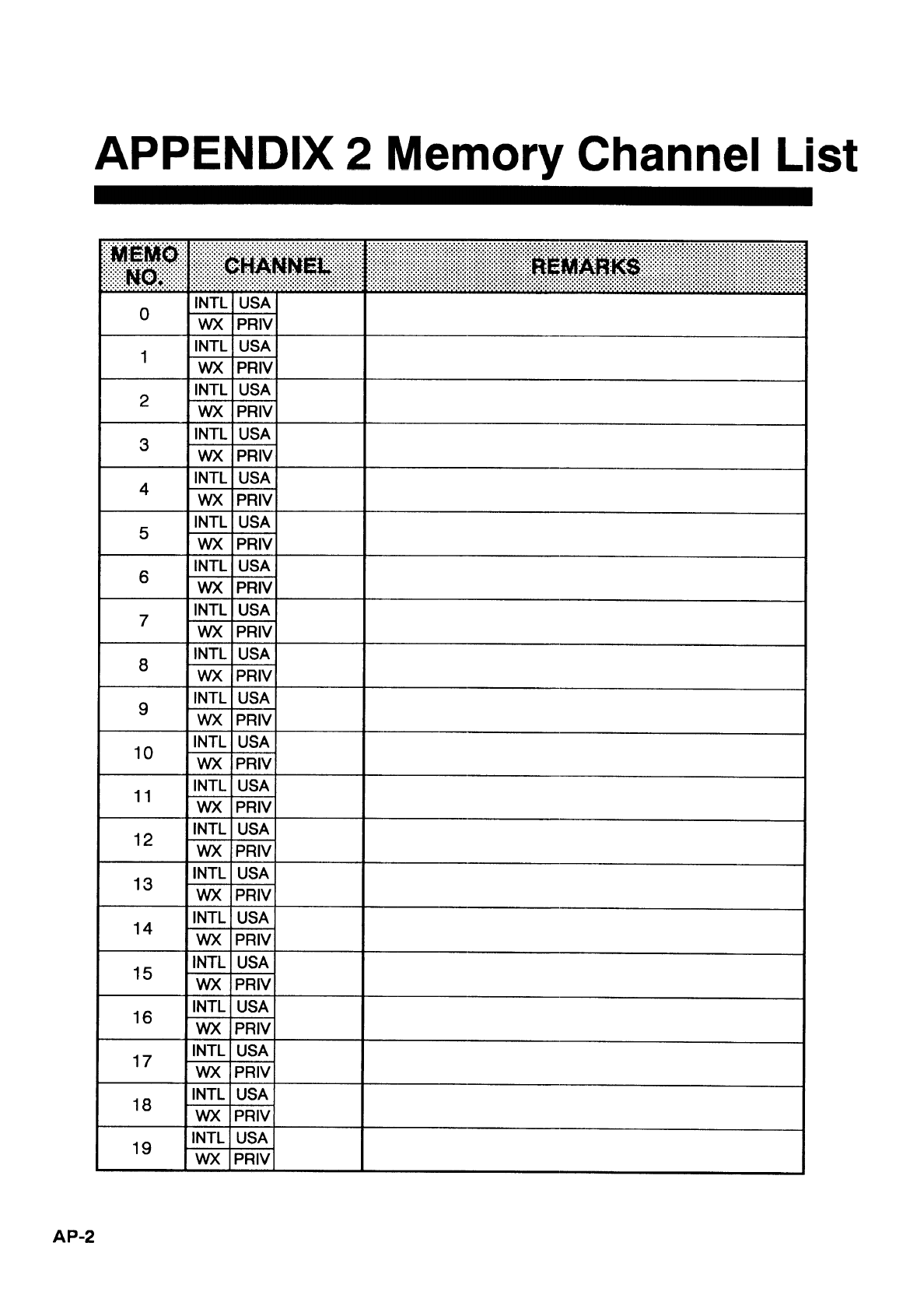
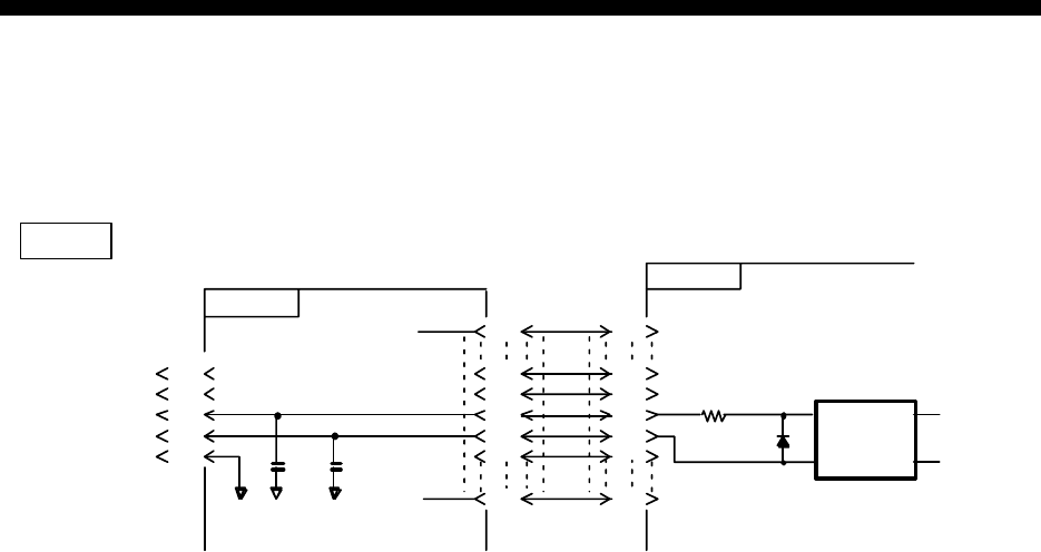
AP-3
APPENDIX 3
Digital Interface (IEC 61162-1 Edition 2)
Input sentences
GGA, GLL, RMA, RMC, ZDA
Schematic diagram
NMEA
05P0620
1
RD-A
J6
RD-B
2
3
4
5
05P0616
R103
560 CR1
U21
1
3
1SS190
6
4
F.GND C35 C36
1000p 1000p
1
30
J11
TLP121-GB
1
21
22
23
24
25
30
J5
21
22
23
24
25
Load requirements as listner
Isolation Optocoupler
Input impedance 560 ohms
Max. Voltage ± 15V
Threshold 4 mA
AP-4
GGA - Global positioning system (GPS) fix data
$--GGA,hhmmss.ss,llll.lll,a,yyyyy.yyy,a,x,xx,x.x,x.x,M,x.x,M,x.x,xxxx*hh<CR><LF>
| | | | | | | | | | | | | | |
| | | | | | | | | | | | | | +-- 11
| | | | | | | | | | | | | +---- 10
| | | | | | | | | | | | +--------- 9
| | | | | | | | | | +---+------------ 8
| | | | | | | | +---+------------------ 7
| | | | | | | +------------------------- 6
| | | | | | +---------------------------- 5
| | | | | +------------------------------- 4
| | | +----+--------------------------------- 3
| +---+--------------------------------------------- 2
+------------------------------------------------------------- 1
1. UTC of position
2. Latitude, N/S
3. Longitude, E/W
4. GPS quality indicator (see note)
5. Number of satllite in use,00-12, may be different from the number in view
6. Horizontal dilution of precision
7. Antenna altitude above/below mean sealevel, m
8. Geoidal separation, m
9. Age of differential GPS data
10. Differential reference station ID, 0000-1023
11. Checksum
NOTE
0 = fix not available or invalid
1 = GPS SPS mode, fix valid
2 = differential GPS, SPS mode, fix valid
3 = GPS PPS mode, fix valid
4 = Real Time Kinetic. Satellite system used in RTK mode with fixed integers
5 = Float RTK. Satellite system used in RTK mode with floating fingers
6 = Estimated (dead reckoning) mode
7 = Manual input mode
8 = Simulator mode
The GPS quality indicator shall not be a null field.
AP-5
GLL - Geographic position - latitude and longitude
$--GLL,llll.lll,a,yyyyy.yyy,a,hhmmss.ss,A,a*hh<CR><LF>
| | | | | | | |
| | | | | | | +------- 6
| | | | | | +--------- 5
| | | | | +----------- 4
| | | | +---------------- 3
| | +------+----------------------- 2
+---+----------------------------------- 1
1. Latitude, N/S
2. Longitude, E/W
3. UTC of position
4. Status: A=data valid, V=data invalid
5. Mode indicator(see note)
6. Checksum
NOTE Positioning system Mode indicator:
A = Autonomous
D = Differential
E = Estimated (dead reckoning)
M = Manual input
S = Simulator
N = Data not valid
The Mode indicator field supplements the Status field. The Status field shall be
set to V=invalid for all values of Operating Mode except for A=Autonomous and
D=Differential. The positioning system Mode indicator and Status field shall not
be null fields.
AP-6
RMA - Recommended minimum navigation information - Loran C data
$--RMA,A,llll.lll,a,yyyyy.yy,a,x.x,x.x,x.x,x.x,x.x,a,a*hh<CR><LF>
| | | | | | | | | | | | |
| | | | | | | | | | | | +------- 10
| | | | | | | | | | | +--------- 9
| | | | | | | | | +---+----------- 8
| | | | | | | | +------------------ 7
| | | | | | | +---------------------- 6
| | | | | | +-------------------------- 5
| | | | | +------------------------------ 4
| | | +----+--------------------------------- 3
| +---+-------------------------------------------- 2
+------------------------------------------------------- 1
1. Status: A=data valid, V=blink, cycle or SNR warning
2. Latitude, degrees N/S
3. Longitude, degrees E/W
4. Time difference A, microseconds
5. Time difference B, microseconds
6. Speed over ground, knots
7. Course over ground, degrees true
8. Magnetic variation(see note 1),degree E/W
9. Mode indicator(see note 2)
10. Checksum
NOTE 1 - Easterly variation(E) subtracts from true course
Westerly variation(W) adds to true course
NOTE 2 Positioning system Mode indicator:
A = Autonomous
D = Differential
E = Estimated (dead reckoning)
M = Manual input
S = Simulator
N = Data not valid
The Mode indicator field supplements the Status field. The Status field
shall be set to V=invalid for all values of Operating Mode except for
A=Autonomous and D=Differential. The positioning system Mode indicator
and Status field shall not be null fields.
AP-7
RMC - Recommended minimum specific GPS/TRANSIT data
$--RMC,hhmmss.ss,A,llll.lll,a,yyyyy.yyy,a,x.x,x.x,xxxxxx,x.x,a,a*hh<CR><LF>
| | | | | | | | | | | | |
| | | | | | | | | | | | +--- 10
| | | | | | | | | | | +----- 9
| | | | | | | | | +--+------- 8
| | | | | | | | +--------------- 7
| | | | | | | +--------------------- 6
| | | | | | +------------------------- 5
| | | | +---+---------------------------- 4
| | +---+---------------------------------------- 3
| +--------------------------------------------------- 2
+---------------------------------------------------------- 1
1. UTC of position fix
2. Status: A=data valid, V=navigation receiver warning
3. Latitude, N/S
4. Longitude, E/W
5. Speed over ground, knots
6. Course over ground, degrees true
7. Date: dd/mm/yy
8. magnetic variation, degrees E/W
9. Mode indicator(see note)
10. Checksum
NOTE Positioning system Mode indicator:
A = Autonomous
D = Differential
E = Estimated (dead reckoning)
M = Manual input
S = Simulator
N = Data not valid
The Mode indicator field supplements the Status field. The Status field
shall be set to V=invalid for all values of Operating Mode except for
A=Autonomous and D=Differential. The positioning system Mode indicator
and Status field shall not be null fields.
ZDA-Data and time
$--ZDA,hhmmss.ss,xx,xx,xxxx,xx,xx*hh<CR><LF>
| | | | | | |
| | | | | | +--------- 7
| | | | | +----------- 6
| | | | +-------------- 5
| | | +------------------ 4
| | +---------------------- 3
| +------------------------- 2
+--------------------------------- 1
1. UTC
2. Day, 01 to 31(UTC)
3. Month, 01 to 12(UTC)
4. Year(UTC)
5. Local zone hours, 00h to +-13h
6. Local zone minutes, 00 to +59
as local hours
7. Checksum

INDEX
A
arrow key ..............................................2-5
Automatic acknowledge .......................1-5
2-8
AUTO squelch ......................................1-3
C
Calling Types ........................................ 5-1
Comply status .......................................4-5
10-1
D
DIS........................................................ 2-1
F
Front panel............................................ 1-1
I
ID number............................................. 2-1
INTL .....................................................1-2
M
MAYDAY ............................................. 3-3
N
Nature of distress .................................. 3-2
O
ON hook ...............................................4-12
P
Power settings .......................................7-5
PRIV .....................................................1-2
PSTN call.............................................. 5-4
Q
QUEUE INDICATION......................... 4-4
R
ROU......................................................2-1
U
USA ......................................................1-2
V
VHF transceiver....................................v
VSWR...................................................8-2