Furuno Fm8900S Operators Manual
FM-8900S to the manual 220afd28-bf6e-4fd9-9332-791bc963f59d
2015-08-11
: Furuno Furuno-Fm8900S-Operators-Manual-800978 furuno-fm8900s-operators-manual-800978 furuno pdf
Open the PDF directly: View PDF ![]() .
.
Page Count: 124 [warning: Documents this large are best viewed by clicking the View PDF Link!]
- OME-56800-A.book.pdf
- IMPORTANT NOTICES
- SAFETY INSTRUCTIONS
- DISTRESS ALERT
- TABLE OF CONTENTS
- FOREWORD
- SYSTEM CONFIGURATION
- 1. OPERATIONAL OVERVIEW
- 1.1 Controls
- 1.2 How to Turn On/Off the Power
- 1.3 Radiotelephone (RT) Screen
- 1.4 How to Adjust the Brilliance of the Display and Panel
- 1.5 How to Select the Channel Region, Channel
- 1.6 Transmission
- 1.7 How to Turn On/Off the Loudspeaker
- 1.8 Quick Selection of CH16
- 1.9 How to Scan Dual Channels (DW)
- 1.10 How to Scan All Channels
- 1.11 How to Set the Auto Acknowledgement
- 1.12 Priority of the System
- 1.13 Intercom
- 1.14 Operation of Session
- 1.15 Replay Function
- 2. DSC OVERVIEW
- 3. DSC DISTRESS OPERATIONS
- 4. DSC GENERAL MESSAGECALLING, RECEIVING
- 5. MENU OPERATION
- 5.1 How to Open/Close the MENU Screen
- 5.2 Handset Volume Setting
- 5.3 Channel Setting
- 5.4 Memory Configuration
- 5.5 How to Print Messages
- 5.6 Position Setting
- 5.7 Date and Time Setting
- 5.8 Timeout Setting
- 5.9 How to Name the Terminal for Intercom
- 5.10 Automatic Switch to CH16
- 5.11 External Alarm Setting
- 5.12 RT Application Setting
- 5.13 Address Book
- 5.14 TX Message Preparation
- 5.15 Log File
- 5.16 How to Set the AUTO ACK Details
- 5.17 Special Messages
- 5.18 Propose Channel Setting
- 5.19 Sound Setting
- 5.20 Alarm Lists
- 6. REMOTE HANDSET
- 6.1 Controls
- 6.2 How to Turn On/Off the Power
- 6.3 Radiotelephone (RT) Screen
- 6.4 How to Adjust the Brilliance and Contrast
- 6.5 How to Select the Channel Region, Channel
- 6.6 Transmission
- 6.7 How to Turn On/Off the Loudspeaker
- 6.8 Quick Selection of CH16
- 6.9 Intercom
- 6.10 How to Change the Terminal ID
- 6.11 Audio setting
- 6.12 How to Test FM-8900S from a Remote Handset
- 6.13 How to Display the Program Versions
- 6.14 Squelch
- 7. MAINTENANCE &TROUBLESHOOTING
- APPENDIX 1 MENU TREE
- APPENDIX 2 MARINE VHF CHANNEL LISTS
- APPENDIX 3 ABBREVIATIONS LIST
- APPENDIX 4 DIGITAL INTERFACE (IEC 61162-1)
- APPENDIX 5 PARTS LIST
- APPENDIX 6 PARTS LOCATION
- SPECIFICATIONS
- INDEX

VHF RADIOTELEPHONE
FM-8900S
OPERATOR'S MANUAL
www.furuno.com
MODEL

The paper used in this manual
is elemental chlorine free.
・FURUNO Authorized Distributor/Dealer
9-52 Ashihara-cho,
Nishinomiya, 662-8580, JAPAN
A : APR 2012
.
Printed in Japan
All rights reserved.
Pub. No. OME-56800-A
*
00017619910
*
*
00017619910
*
(YOTA ) FM-8900S
*
00017619910
*
*
00017619910
*
* 0 0 0 1 7 6 1 9 9 1 0 *

i
IMPORTANT NOTICES
General
• This manual has been authored with simplified grammar, to meet the needs of international us-
ers.
• The operator of this equipment must read and follow the descriptions in this manual. Wrong op-
eration or maintenance can cancel the warranty or cause injury.
• Do not copy any part of this manual without written permission from FURUNO.
• If this manual is lost or worn, contact your dealer about replacement.
• The contents of this manual and equipment specifications can change without notice.
• The example screens (or illustrations) shown in this manual can be different from the screens
you see on your display. The screens you see depend on your system configuration and equip-
ment settings.
• Save this manual for future reference.
• Any modification of the equipment (including software) by persons not authorized by FURUNO
will cancel the warranty.
• All brand and product names are trademarks, registered trademarks or service marks of their
respective holders.
How to discard this product
Discard this product according to local regulations for the disposal of industrial waste. For disposal
in the USA, see the homepage of the Electronics Industries Alliance (http://www.eiae.org/) for the
correct method of disposal.
How to discard a used battery
Some FURUNO products have a battery(ies). To see if your product has a battery, see the chapter
on Maintenance. Follow the instructions below if a battery is used. Tape the + and - terminals of
battery before disposal to prevent fire, heat generation caused by short circuit.
In the European Union
The crossed-out trash can symbol indicates that all types of batteries
must not be discarded in standard trash, or at a trash site. Take the
used batteries to a battery collection site according to your national
legislation and the Batteries Directive 2006/66/EU.
In the USA
The Mobius loop symbol (three chasing arrows) indicates that Ni-Cd
and lead-acid rechargeable batteries must be recycled. Take the
used batteries to a battery collection site according to local laws.
In the other countries
There are no international standards for the battery recycle symbol. The number of symbols can
increase when the other countries make their own recycle symbols in the future.
Cd
Ni-Cd Pb
ii
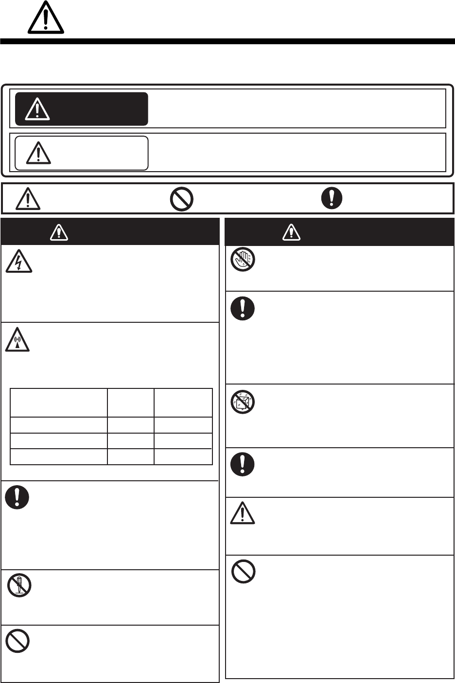
SAFETY INSTRUCTIONS
Indicates a condition that can cause death or serious injury
if not avoided.
Indicates a condition that can cause minor or moderate
injury if not avoided.
The user must read the appropriate safety instructions before attempting to install or operate
the equipment.
WARNING
CAUTION
Warning, Caution Prohibitive Action Mandatory Action
WARNING WARNING
Do not open the equipment.
Hazardous voltage which can cause
electrical shock, burn or serious
injury exists inside the equipment.
Only qualified personnel should work
inside the equipment.
Immediately turn off the power at
the switchboard if water leaks into
the equipment or the equipment is
emitting smoke or fire.
Continued use of the equipment can
cause fire or electrical shock. Contact
a FURUNO agent for service.
Do not disassemble or modify the
equipment.
Fire, electrical shock or serious injury
can result.
Do not place liquid-filled containers
on the top of the equipment.
Fire or electrical shock can result if a
liquid spills into the equipment.
Do not operate the equipment with
wet hands.
Electrical shock can result.
Turn off the power immediately if you
feel the equipment is behaving
abnormally.
Turn off the power at the switchboard if
the equipment becomes abnormally
warm or is emitting odd noises. Contact
a FURUNO dealer or agent for advice.
Make sure no rain or water splash
leaks into the equipment.
Fire or electrical shock can result if
water leaks in the equipment.
Use the proper fuse.
Use of the wrong fuse can cause fire or
electrical shock.
Do not approach the antenna
closer than listed below when it
is transmitting.
The antenna emits radio waves that
can be harmful to the human body.
RF power density on
antenna aperture Distance Description
required by
100 W/m2
10 W/m2
2 W/m2
IEC 60945
IEC 60945
MPE by FCC
(MPE: Minimum Permissible Exposure)
Any repair work must be done by a
licensed radio technician.
Improper repair work can cause fire or
electrical shock.
Do not operate the [DISTRESS] key
except in case of a life-endangering
situation on your vessel.
Operating the [DISTRESS] key
transmits the distress alert. Accidental
transmission may prevent search and
rescue operations for actual emergency.
If the distress alert is accidentally
transmitted, contact the nearest station
to cancel the alert.
0.89 m
0.39 m
0.12 m
SAFETY INSTRUCTIONS
iii
The TFT LCD is constructed using the latest LCD techniques, and displays
99.99% of its pixels. The remaining 0.01% of the pixels may drop out or
blink, however this is not an indication of malfunction.
About the TFT LCD
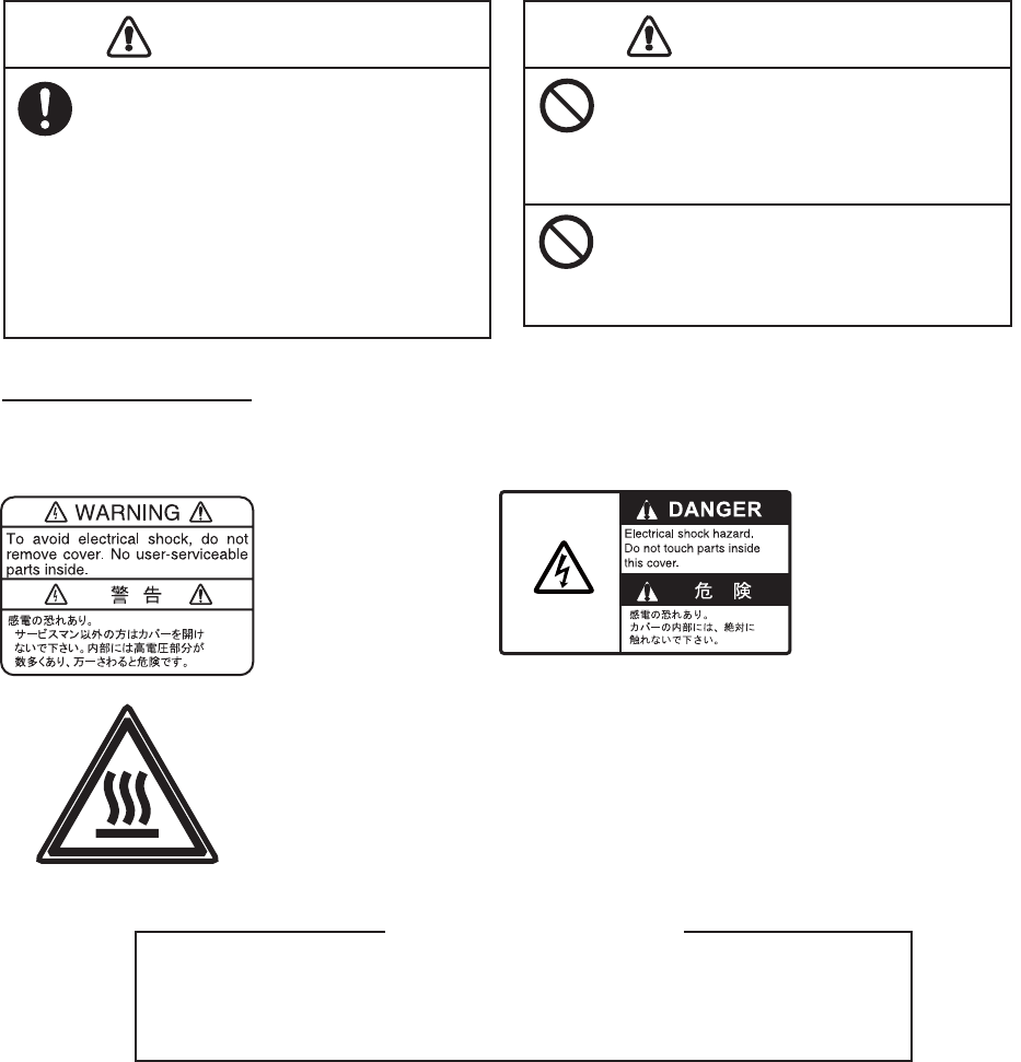
Warning labels are attached to the equipment. Do not remove any label. If a label is missing or
damaged, contact a FURUNO agent or dealer about replacement.
Name: Warning Label 1
Type: 86-003-1011-3
Code No.: 100-236-233-10
CAUTION
WARNING LABELS
Do not apply strong pressure to
the LCD, which is made of glass.
Injury can result if the LCD breaks.
Name: Warning Label
Type: 14-055-4202-1
Code No.: 100-245-221-10
Name: High Temp Warning Label
Type: 05-089-2142-0
Code No.: 100-301-620-00
CAUTION
If the distress alert is accidentally
transmitted, contact the nearest
coast station and inform them of the
accidental
transmission, providing the
following data:
a) Ship's name
b) Ship's call sign and DSC number
c) Position at time of transmission
d) Time of transmission
Do not touch any part of the
antenna when the equipment is
transmitting.
Electrical shock can result.
iv
DISTRESS ALERT
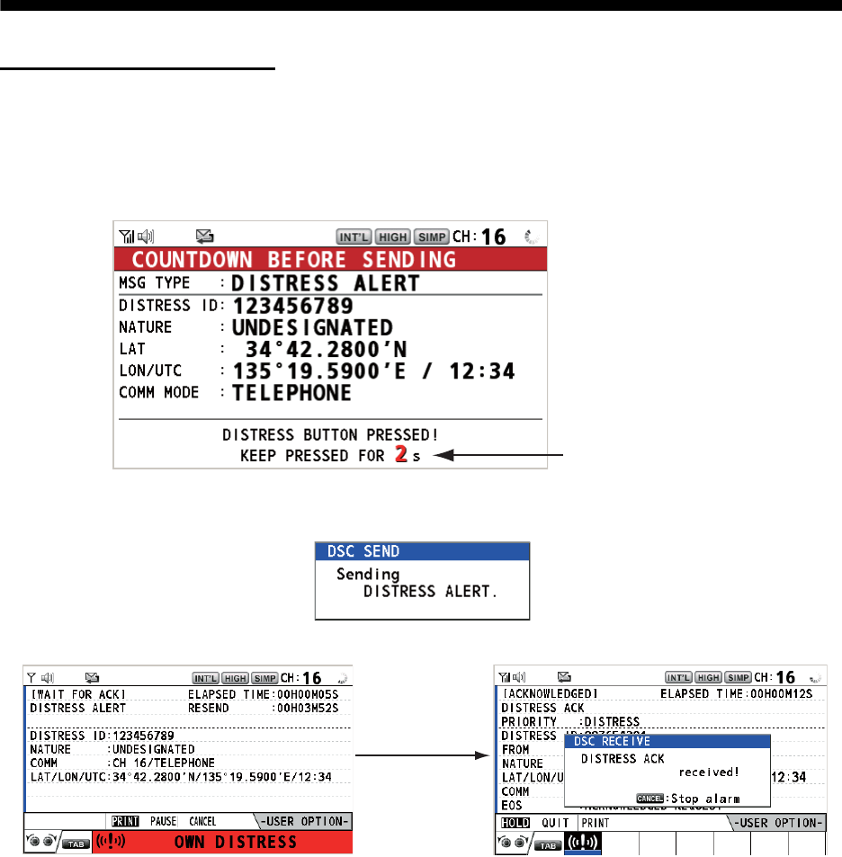
How to send a distress alert
Below is the procedure for transmitting a distress alert via radiotelephone. Transmit the distress
alert when a life-endangering situation occurs on your vessel.
1. Open the DISTRESS key cover then press and hold the DISTRESS key for four seconds. The
following screen appears.
2. When the message "Sending DISTRESS ALERT." appears on the screen, release the DIS-
TRESS key. The audio alarm sounds for two seconds.
After the distress alert has been sent, the following screens appear in order.
3. The audio alarm sounds. Press the CANCEL key to silence the audio alarm.
4. Communicate with the coast station via radiotelephone (CH16) as below.
a) Say “MAYDAY” three times.
b) Say “This is ...” name of your ship and call sign three times.
c) Give nature of distress and assistance needed.
d) Give description of your ship (type, color, number of persons onboard, etc.).
Note: If you do not receive the distress alert acknowledge call, the equipment automatically re-
transmits the distress alert after 3 min 30 seconds to 4 min 30 seconds. Then the equipment
awaits the distress alert acknowledge call. This is repeated until the distress alert is acknowl-
edged.
Countdown message
When distress
acknowledge
call is received
by coast station
DISTRESS ALERT
v
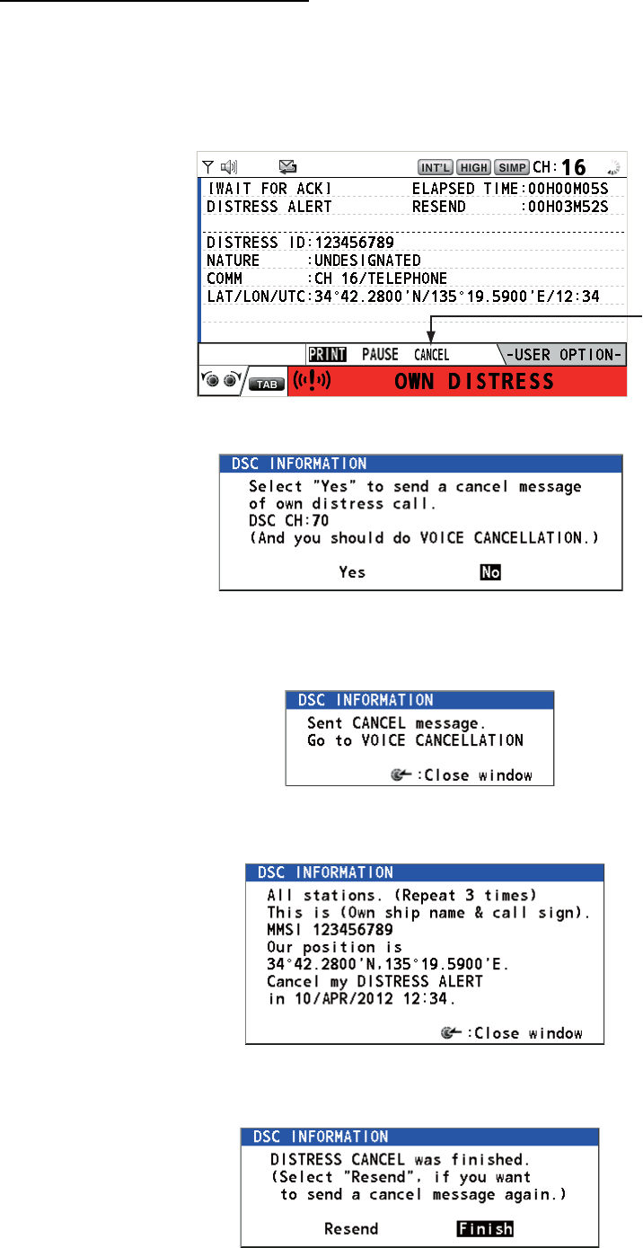
How to cancel the distress alert
You can cancel the distress alert while it is being sent or while waiting for its acknowledgement as
follows.
1. Rotate the CHANNEL/ENTER knob to select [CANCEL] in the user options area then push
the knob.
The following message appears on the screen.
2. Rotate the CHANNEL/ENTER knob to select [Yes] then push the knob to send the distress
cancel call on CH70. After transmitting the distress cancel call, the following message ap-
pears on the screen.
3. Push the CHANNEL/ENTER knob to erase the message. The following message appears on
the screen.
4. Communicate with all ships via radiotelephone referring to the message at step 3.
5. Push the CHANNEL/ENTER knob. The following message appears on the screen.
6. With [Finish] selected, push the CHANNEL/ENTER knob.

vi
TABLE OF CONTENTS
FOREWORD ...................................................................................................................ix
SYSTEM CONFIGURATION ..........................................................................................xi
1. OPERATIONAL OVERVIEW .................................................................................1-1
1.1 Controls...................................................................................................................... 1-1
1.2 How to Turn On/Off the Power................................................................................... 1-2
1.3 Radiotelephone (RT) Screen ..................................................................................... 1-2
1.4 How to Adjust the Brilliance of the Display and Panel ............................................... 1-3
1.5 How to Select the Channel Region, Channel............................................................. 1-3
1.6 Transmission.............................................................................................................. 1-4
1.7 How to Turn On/Off the Loudspeaker ........................................................................ 1-5
1.8 Quick Selection of CH16 ............................................................................................ 1-5
1.9 How to Scan Dual Channels (DW)............................................................................. 1-5
1.10 How to Scan All Channels.......................................................................................... 1-6
1.11 How to Set the Auto Acknowledgement..................................................................... 1-7
1.12 Priority of the System ................................................................................................. 1-7
1.13 Intercom ..................................................................................................................... 1-8
1.14 Operation of Session.................................................................................................. 1-9
1.15 Replay Function ....................................................................................................... 1-12
2. DSC OVERVIEW....................................................................................................2-1
2.1 What is DSC?............................................................................................................. 2-1
2.2 DSC Messages .......................................................................................................... 2-1
2.3 Audio Alarms.............................................................................................................. 2-2
2.4 Description of Call Screens........................................................................................ 2-3
2.4.1 RX calls .......................................................................................................... 2-3
2.4.2 TX calls .......................................................................................................... 2-4
3. DSC DISTRESS OPERATIONS ............................................................................3-1
3.1 How to Send a Distress Alert ..................................................................................... 3-1
3.1.1 How to send a distress alert by DISTRESS key with distress information
not edited ....................................................................................................... 3-1
3.1.2 How to send a distress alert by DISTRESS key with distress information
edited ............................................................................................................. 3-3
3.2 How to Receive a Distress Alert................................................................................. 3-4
3.3 How to Send a Distress Relay on Behalf of a Ship in Distress ................................ 3-10
3.3.1 How to send a distress relay to a coast station............................................ 3-10
3.3.2 How to send a distress relay to all ships...................................................... 3-11
3.4 How to Receive a Distress Relay............................................................................. 3-13
3.5 How to Cancel the Distress Alert ............................................................................. 3-13
4. DSC GENERAL MESSAGE CALLING, RECEIVING............................................4-1
4.1 Individual Call.............................................................................................................4-1
4.1.1 How to send an individual call........................................................................ 4-1
4.1.2 How to receive an individual call .................................................................... 4-4
4.2 Group Call .................................................................................................................. 4-6
4.2.1 How to send a group call................................................................................ 4-6
4.2.2 How to receive a group call............................................................................ 4-7
4.3 PSTN Call .................................................................................................................. 4-8
4.3.1 How to send a PSTN call ............................................................................... 4-8
4.3.2 How to receive a PSTN call ......................................................................... 4-10
4.3.3 Note after sending a PSTN call.................................................................... 4-10
TABLE OF CONTENTS
vii
4.4 All Ships Call ............................................................................................................4-11
4.4.1 How to send an all ships call ........................................................................4-11
4.4.2 How to receive an all ships call ....................................................................4-12
4.5 Position Call..............................................................................................................4-13
4.5.1 How to request other ship's position.............................................................4-13
4.5.2 Other ship requests your position.................................................................4-15
4.6 How to Receive a Polling Request ...........................................................................4-15
4.6.1 Automatic reply.............................................................................................4-15
4.6.2 Manual reply.................................................................................................4-16
4.7 Neutral Craft Call ......................................................................................................4-16
4.7.1 How to send a neutral craft call ....................................................................4-16
4.7.2 How to receive a neutral craft call ................................................................4-17
4.8 Medical Transport Call..............................................................................................4-18
4.8.1 How to send a medical transport call ...........................................................4-18
4.8.2 How to receive a medical transport call........................................................4-19
5. MENU OPERATION ..............................................................................................5-1
5.1 How to Open/Close the MENU Screen ......................................................................5-1
5.2 Handset Volume Setting.............................................................................................5-2
5.3 Channel Setting..........................................................................................................5-2
5.3.1 Channel region ...............................................................................................5-2
5.3.2 Memory ..........................................................................................................5-2
5.4 Memory Configuration ................................................................................................5-3
5.5 How to Print Messages...............................................................................................5-4
5.6 Position Setting...........................................................................................................5-4
5.7 Date and Time Setting................................................................................................5-5
5.8 Timeout Setting ..........................................................................................................5-5
5.9 How to Name the Terminal for Intercom.....................................................................5-6
5.10 Automatic Switch to CH16..........................................................................................5-7
5.11 External Alarm Setting................................................................................................5-7
5.12 RT Application Setting ................................................................................................5-8
5.13 Address Book .............................................................................................................5-8
5.13.1 List for address data.......................................................................................5-8
5.13.2 How to register addresses..............................................................................5-9
5.13.3 How to edit addresses..................................................................................5-10
5.13.4 How to delete addresses..............................................................................5-11
5.13.5 How to create a DSC message with registered address..............................5-11
5.14 TX Message Preparation..........................................................................................5-12
5.14.1 List for message files....................................................................................5-12
5.14.2 Individual calls ..............................................................................................5-13
5.14.3 Group calls ...................................................................................................5-14
5.14.4 PSTN calls....................................................................................................5-15
5.14.5 Test calls ......................................................................................................5-15
5.14.6 How to edit prepared messages...................................................................5-16
5.14.7 How to send prepared messages.................................................................5-16
5.14.8 How to delete prepared messages...............................................................5-17
5.15 Log File.....................................................................................................................5-17
5.15.1 How to open a log file...................................................................................5-17
5.15.2 How to delete log files ..................................................................................5-18
5.16 How to Set the AUTO ACK Details...........................................................................5-19
5.17 Special Messages ....................................................................................................5-20
5.18 Propose Channel Setting..........................................................................................5-20
5.19 Sound Setting...........................................................................................................5-20
5.20 Alarm Lists................................................................................................................5-21
TABLE OF CONTENTS
viii
6. REMOTE HANDSET..............................................................................................6-1
6.1 Controls...................................................................................................................... 6-1
6.2 How to Turn On/Off the Power................................................................................... 6-2
6.3 Radiotelephone (RT) Screen ..................................................................................... 6-2
6.4 How to Adjust the Brilliance and Contrast.................................................................. 6-3
6.5 How to Select the Channel Region, Channel............................................................. 6-3
6.6 Transmission.............................................................................................................. 6-4
6.7 How to Turn On/Off the Loudspeaker ........................................................................ 6-5
6.8 Quick Selection of CH16 ............................................................................................ 6-5
6.9 Intercom .....................................................................................................................6-5
6.10 How to Change the Terminal ID................................................................................. 6-6
6.11 Audio setting .............................................................................................................. 6-6
6.12 How to Test FM-8900S from a Remote Handset ....................................................... 6-8
6.13 How to Display the Program Versions ....................................................................... 6-8
6.14 Squelch ...................................................................................................................... 6-8
7. MAINTENANCE & TROUBLESHOOTING ............................................................7-1
7.1 Daily Test ...................................................................................................................7-1
7.2 Maintenance............................................................................................................... 7-2
7.3 Simple Troubleshooting ............................................................................................. 7-2
7.4 Warning and Caution Messages ................................................................................ 7-3
7.5 Test Call ..................................................................................................................... 7-4
APPENDIX 1 MENU TREE .......................................................................................AP-1
APPENDIX 2 MARINE VHF CHANNEL LISTS ........................................................AP-3
APPENDIX 3 ABBREVIATIONS LIST....................................................................AP-13
APPENDIX 4 DIGITAL INTERFACE (IEC 61162-1) ...............................................AP-15
APPENDIX 5 PARTS LIST......................................................................................AP-20
APPENDIX 6 PARTS LOCATION...........................................................................AP-21
SPECIFICATIONS .....................................................................................................SP-1
INDEX.......................................................................................................................... IN-1

ix
FOREWORD
A Word to the Owner of the FM-8900S
Congratulations on your choice of the FURUNO FM-8900S VHF Radiotelephone. We are confi-
dent you will see why the FURUNO name has become synonymous with quality and reliability.
Since 1948, FURUNO Electric Company has enjoyed an enviable reputation for innovative and
dependable marine electronics equipment. This dedication to excellence is furthered by our ex-
tensive global network of agents and dealers.
Your equipment is designed and constructed to meet the rigorous demands of the marine envi-
ronment. However, no machine can perform its intended function unless properly installed and
maintained. Please carefully read and follow the operation and maintenance procedures set forth
in this manual.
We would appreciate feedback from you, the end-user, about whether we are achieving our pur-
poses.
Thank you for considering and purchasing FURUNO equipment.
Features
The FM-8900S is a cost-effective all-in-one marine VHF radio system consisting of a 25 W VHF
radiotelephone, a DSC modem, and a CH70 watchkeeping receiver. It complies with GMDSS car-
riage requirements for safety and general communications.
The FM-8900S offers semi-duplex voice communication on ITU channels in the marine mobile
VHF band. The features include Scanning Dual Channels (DW) which allows a continuous watch
on CH16 and another selected frequency.
Data is displayed on a large, easy-to-read color LCD. Operation is simplified by the use of few
keys and easy-to-follow menus.
The built-in DSC function produces and receives digital selective callings for quick and efficient
establishment of distress, urgency, safety and routine communications with other ships and coast
stations that install any VHF DSC facilities.
Full Class-A DSC functions are provided for distress alert transmission and reception, as well as
the general call formats (Individual telephone, All Ships, and Group call). Distress alert can be
readily transmitted but an arrangement is provided to prevent accidental activation. The FM-
8900S maintains a continuous watch on CH70 even while another VHF channel is in use. Aural
and visual alarms are given to incoming DSC messages.
The main features are
General
• Fully meets the following regulations: EN 300 698-1, EN 301 925, ITU-R M.493-13,
ITU-R M.541-9, ITU-R M.689-2, EN 300 338-1, EN 300 338-2.
• Automatic entry of position with manual override
• Optional printer can automatically print out DSC received messages and test results.
FOREWORD
x
DSC
• Distress, urgency, safety and routine calling
• File editing capability for readiness in case of emergency
• PSTN (Public Switched Telephone Network) capability standard
• Log stores 50 each of latest general, distress and transmitted messages, in separate memory
blocks.
• Selectable an address from the AIS targets list with connection of FURUNO AIS Transponder/
Receiver
VHF
• Voice communication
• Scanning of channels on VHF
• Simplified setting of channel
• Replay of the latest receiving voice, which is automatically recorded, for 120 seconds
• Max. 4 remote stations (RB-8900) can be connected (not available for DSC function).
Program Number
xx: minor change
Location PC board Program No. Version
FM-8900S MAIN (05P0843) 0550249 01.xx
HS-8900 HS CONT (05P0781B) 0550250 01.xx
xi
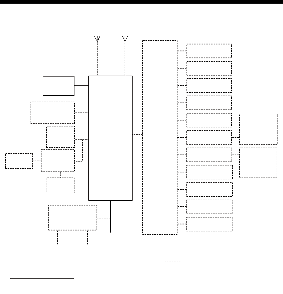
SYSTEM CONFIGURATION
: STANDARD
: OPTIONAL or LOCAL SUPPLY
JUNCTION
BOX
IF-8900
TRX
ANT
CH70
RX ANT
TRANSCEIVER
UNIT
FM-8900S
24 VDC
AC/DC POWER
SUPPLY UNIT
PR-240
24 VDC
Battery
100-115/200-230 VAC
1ø, 50/60 Hz
HANDSET
HS-2003
EXTERNAL
LOUDSPEAKER
SEM-21Q
PRINTER
PP-510/
PP-8800A
PRINTER
PP-510
PRINTER
INTERFACE
IF-8500
OTHER
RADIO
NAV
EQUIPMENT
VDR
ALARM
SYSTEM
ALARM UNIT
IC-350
INS/AIS/
PLOTTER
MIC RECEPTACLE
BOX RBD-VHF (B)
MIC RECEPTACLE
BOX RBD-VHF (B)
REMOTE STATION
RB-8900/RB-8900-W
REMOTE STATION
RB-8900/RB-8900-W
REMOTE STATION
RB-8900/RB-8900-W
REMOTE STATION
RB-8900/RB-8900-W
ANALOG WING
HANDSET
HS-6000FZ5/
HS-6000FZ11
ANALOG WING
HANDSET
HS-6000FZ5/
HS-6000FZ11
Environmental category
Antenna units: Exposed to the weather
All other units: Protected from the weather
SYSTEM CONFIGURATION
xii
This page is intentionally left blank.
1-1
1. OPERATIONAL OVERVIEW
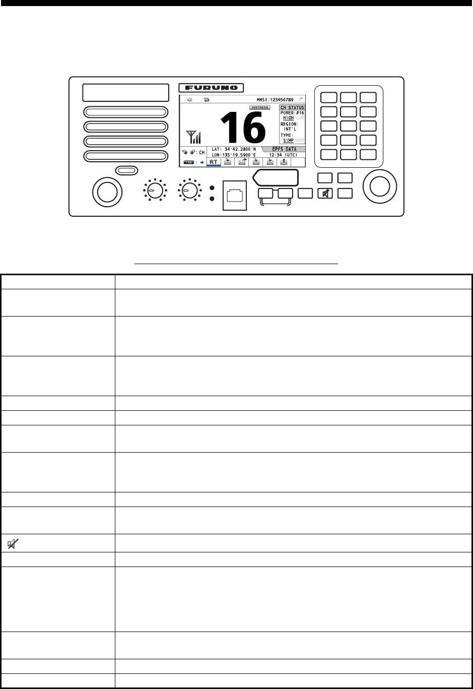
1.1 Controls
Transceiver unit
Description of controls for transceiver unit
Control Function
VOLUME/PWR knob • Turns the power on or off.
• Adjusts the volume.
CHANNEL/ENTER
knob
• Rotate to select channel.
• Rotate to select menu items or change the page in multi-page screens
(e.g., log data); push to confirm a selection.
SQUELCH knob Rotate to adjust the squelch. The squelch mutes the audio output in the ab-
sence of an incoming signal. AUTO position automatically reduces white
noise.
DISTRESS key Press and hold down the key four seconds to transmit the distress alert.
DISTRESS MSG key Composes DSC TX message for DISTRESS ALERT.
OTHER DSC MSG
key
Composes DSC TX message except DISTRESS ALERT and DROBOSE
(Distress Relay On Behalf Of Someone Else).
DROBOSE MSG key Composes DSC TX message for DROBOSE (Distress Relay On Behalf Of
Someone Else). Press the DISTRESS MSG key and the OTHER DSC
MSG key simultaneously.
BRILL key Adjusts the brilliance.
TAB key • Switches control to the tab area.
• Switches the session.
key Turns the main speaker on or off.
MENU key Opens/closes the menu.
CANCEL key • Cancels the creation of the DSC message currently being created.
• Silences the audio alarm.
• Erases error message and pop-up message.
• Returns previous layer in multi-layer menu.
• Erases character input.
RT/REGION key • Switches to the RT (radiotelephone) screen.
• Opens/closes the option window for channel region.
HI/LO key Changes the output power to high (25 W) or low (1 W).
CH16 key Switches to the RT (radiotelephone) screen and sets CH16.
RT/
REGION
HI/LO
123
46
97
5
8
0
COMPOSE
DROBOSE MSG
PUSH TO ENTER
DISTRESS
MSG
OTHER
DSC MSG
BRILL
TAB MENU
CANCEL
HANDSET VOLUME
PWR OFF
ALARM
DISTRESS
Keep pressed for 4 sec in case
of DISTRESS. The alert is
transmitted with steady lighting.
AUTO
SQUELCH
CHANNEL
CH16
REPLAY
DW/
SCAN
1. OPERATIONAL OVERVIEW
1-2
1.2 How to Turn On/Off the Power
Rotate the VOLUME/PWR knob clockwise to turn on the power. The RT screen ap-
pears.
To turn off the power, rotate the VOLUME/PWR knob counterclockwise to the OFF po-
sition.
1.3 Radiotelephone (RT) Screen
Turn the power on, or press the RT/REGION key to show the radiotelephone (RT)
screen. This is where you set up the transceiver unit, and communicate by voice.
0 to 9 keys • Enter alphabet, numeric or symbol.
• Direct selection of corresponding function on menu and applicable
screens.
DW/SCAN key • Opens the option window for DW or SCAN.
• Cancels DW or SCAN in process.
REPLAY key Opens the replay screen.
ALARM lamps Top: Flashes in red when receiving distress alert, distress and urgency
messages.
Bottom: Flashes in green when receiving safety and routine messages, and
when daily test is completed.
The flashing of a lamp for receiving a DSC message is in synch with the au-
dio alarm.
The flashing cycle for both top and bottom lamps is 200 msec (lighting) →
200 msec (off) → 200 msec (lighting) → 200 msec (off) → …
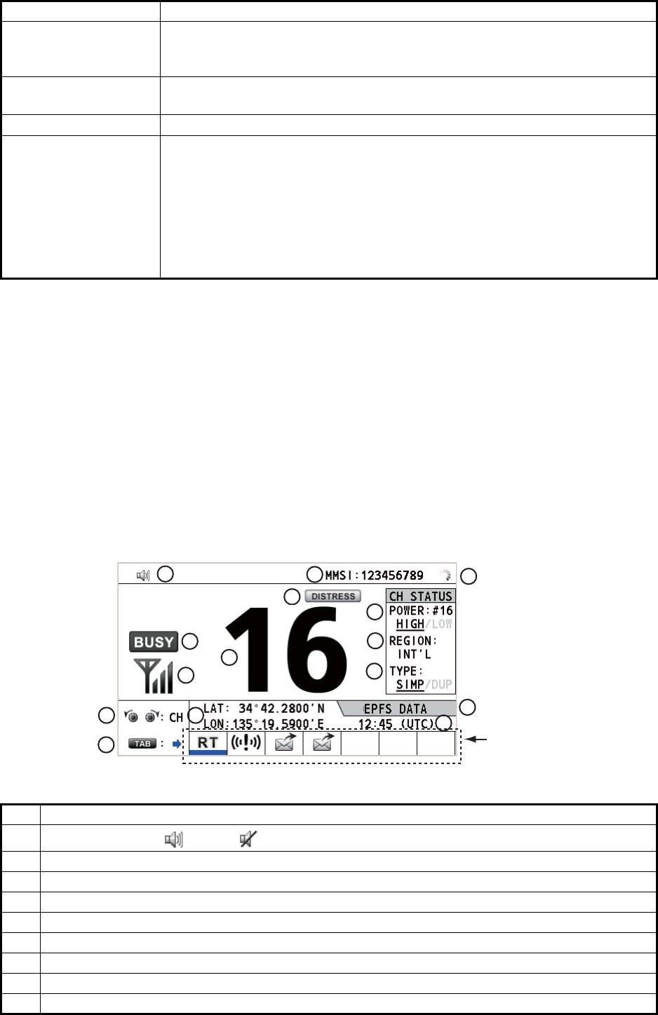
No. Meaning
1Loudspeaker on ( ) or off ( )
2 This icon appears when the channel is busy.
3 Intensity of reception (This icon does not appear while transmitting.)
4 Own ship’s MMSI (nine digits)
5 Spinner rotates when the equipment is functioning normally.
6 This icon appears when the frequency is for distress.
7 Channel
8 Output power ([HIGH], [LOW])
9 Channel region ([INT’L], [USA], [CANADA], [INLAND-W], [PRIVATE])
Control Function
Tab area: Sessions
in progress
2
1
3
45
6
8
9
11
10
12
13 15
14
7
Radiotelephone (RT) screen on the transceiver unit
1. OPERATIONAL OVERVIEW
1-3
1.4 How to Adjust the Brilliance of the Display and
Panel
You can adjust the brilliance of the display and the panel for transceiver unit.
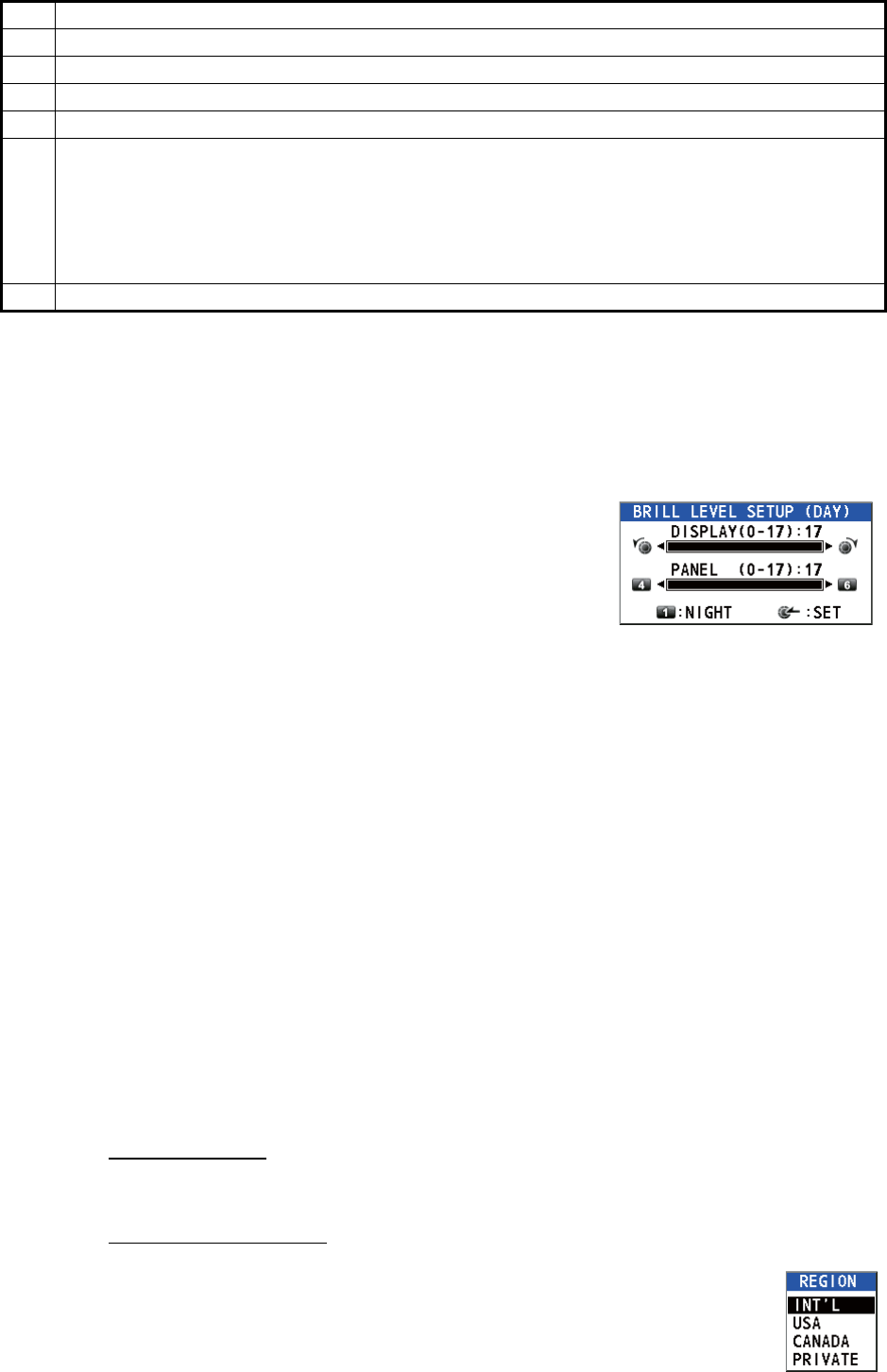
1. Press the BRILL key to show the [BRILL LEVEL
SETUP] window.
If necessary, press the 1 key to switch the [DAY/
NIGHT] mode.
Note: When switching the [DAY/NIGHT] mode
with the 1 key, the [BRILL LEVEL SETUP] win-
dow closes. Press the BRILL key again to show the window.
2. To adjust the [DISPLAY] brilliance, rotate the CHANNEL/ENTER knob or press
the BRILL key. (Default setting: 17 for [DAY], 7 for [NIGHT])
3. To adjust the [PANEL] brilliance, press the 4 (decrease the setting) or 6 (increase
the setting) key. (Default setting: 17 for [DAY], 12 for [NIGHT])
4. Push the CHANNEL/ENTER knob to save the settings and close the window. To
cancel the settings, press the CANCEL key instead of the CHANNEL/ENTER
knob to close the window.
Note 1: The equipment keeps values for [DAY] and [NIGHT] separately.
Note 2: The window closes automatically when there is no operation for four seconds.
Note 3: When you turn on the power with the display brilliance set to 0, the setting au-
tomatically changes to 1.
1.5 How to Select the Channel Region, Channel
Channel region
You can select the channel region by the RT/REGION key or the [REGION] menu.
By the RT/REGION key
1. Press the RT/REGION key to open the [REGION] option on the RT
screen.
2. Rotate the CHANNEL/ENTER knob to select the channel region de-
sired then push the knob.
10 Channel type ([SIMP]: Simplex, [DUP]: Duplex)
11 Guidance: Rotate the CHANNEL/ENTER knob to select channel.
12 Guidance: Press the TAB key to switch the session.
13 Own ship’s position (LAT: Latitude, LON: Longitude)
14
Method of data input
[EPFS DATA]: The position and time data from EPFS.
[EPFS (OFFLINE)]: Indicates no position data from EPFS for ten minutes.
[EPFS (OLD)]: Indicates no position data from EPFS for four hours.
[MANUAL INPUT]: Set the position and time data manually.
[NO INFO]: No position and time data.
15 Time (UTC: universal time coordinated) of the position fix
No. Meaning
1. OPERATIONAL OVERVIEW
1-4
By the [REGION] menu
See paragraph 5.3.1.
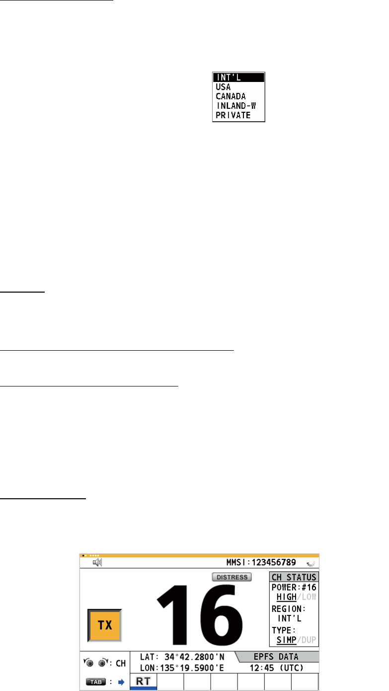
1. Press the MENU key to open the [MENU] screen.
2. Rotate the CHANNEL/ENTER knob to select [CH MODE] then push the knob.
3. Rotate the CHANNEL/ENTER knob
to select [REGION] then push the
knob.
4. Rotate the CHANNEL/ENTER knob to select the channel region desired then
push the knob.
Note: Private channels are available only where permitted by the authorities. The
[USA], [CANADA], [INLAND-W], [PRIVATE] can also be set by a qualified service
technician.
Channel
The channel can be set manually on the RT screen. Enter the channel by one of the
methods below.
Enter channel with the CHANNEL/ENTER knob:
Rotate the CHANNEL/ENTER knob on the RT screen.
Enter channel with the numeric keys:
Use the numeric keys to enter channel on the RT screen then push the CHANNEL/
ENTER knob. The setting is automatically confirmed two seconds after entering, with-
out pushing the CHANNEL/ENTER knob.
1.6 Transmission
How to transmit
Press the PTT (push-to-talk) switch on the handset with off hook to talk, and release
it to listen for a response. "TX" appears on the screen during transmission.
The following options are available.
• [INT’L]: International mode
• [CANADA]: CANADA mode
• [PRIVATE]: Private channel mode
• [USA]: USA mode
• [INLAND-W]: Inland waterway mode
Only permitted channel
regions are displayed,
which are set by the
installer of the equipment.
1. OPERATIONAL OVERVIEW
1-5
How to change the output power
Press the HI/LO key to change the output power between high and low alternately.
[HIGH] or [LOW] with underline appears in the [CH STATUS] area on the RT screen
depending on your selection.
1.7 How to Turn On/Off the Loudspeaker
You can turn the loudspeaker (other than DSC communication, error, and key beep)
on or off.
1. Press the key to alternately disable or enable the loudspeaker.
2. To adjust the volume of the loudspeaker, rotate the VOLUME/PWR knob (cw: vol-
ume up, ccw: volume down).
1.8 Quick Selection of CH16
Press the CH16 key to select CH16. The CH16 (156.8 MHz) is the international fre-
quency for distress traffic and for calling by radiotelephone. The CH16 can also be
used by ship stations for call and reply. To facilitate the reception of distress calls and
distress traffic, all transmissions on CH16 should be kept to a minimum and should not
exceed one minute. Before transmitting on the CH16, a station should listen on this
frequency for a reasonable period to make sure that no distress traffic is being sent.
1.9 How to Scan Dual Channels (DW)
The DW function permits watch on CH16 and an operator-selected channel. CH16
and another channel are watched at intervals of 0.15 seconds and one second, re-
spectively.
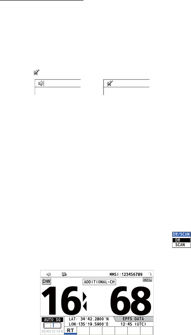
1. Select the other channel to watch then press the DW/SCAN key to
show the [DW/SCAN] option.
2. With [DW] selected, push the CHANNEL/ENTER knob. The following screen ap-
pears (channel 68 is selected in the example).
Speaker ON Speaker OFF
1. OPERATIONAL OVERVIEW
1-6
When the receiver detects a carrier and the squelch opens, the following occurs.
• When the squelch opens on the additional channel, the receiver continues
scanning dual channels.
• When the squelch opens on the CH16, the CH16 is set.
When the squelch closes, the scanning on dual channels restarts.
To stop the scanning on dual channels, do one of the following:
• Press the CANCEL key.
• Press the CH16 key.
• Press the DISTRESS key.
• Press the DW/SCAN key.
• Off hook a handset if there is one on hook.
• Press the PTT switch of a handset that is off hook. In this case, press the PTT switch
again to transmit.
• Activate another session.
• Select [HOLD] in the RT session.
• Select [QUIT] in the RT session.
• Press the MENU key.
• Press the RT/REGION key.
1.10 How to Scan All Channels
The receiver scans all channels at intervals of 0.15 seconds in the selected channel
mode in ascending channel order, watching CH16 between channels as below:
Note: TX is disabled when scanning.
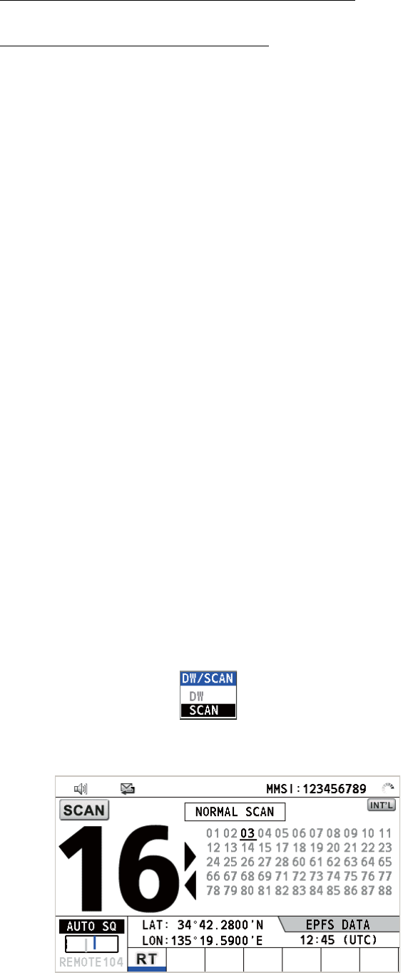
1. Press the DW/SCAN key to show the [DW/SCAN] option.
2. With [SCAN] selected, push the CHANNEL/ENTER knob. The scanning starts
and the "SCAN" icon appears on the screen.
01 16 02 16 03 16 04...
16 88 16 87 16 86 16...

1. OPERATIONAL OVERVIEW
1-7
When the receiver detects a carrier and the squelch opens, the scanning is
stopped on that channel.
• When the squelch opens on the channel except CH16, dual watch starts on it
and CH16.
• When the squelch opens on the CH16, the CH16 is set.
When the squelch closes, the scanning restarts.
To stop the scanning, do one of the following:
• Press the CANCEL key.
• Press the CH16 key.
• Press the DISTRESS key.
• Press the DW/SCAN key.
• Off hook a handset if there is one on hook.
• Press the PTT switch of a handset that is off hook. In this case, press the PTT switch
again to transmit.
• Activate another session.
• Select [HOLD] in the RT session.
• Select [QUIT] in the RT session.
• Press the MENU key.
• Press the RT/REGION key.
1.11 How to Set the Auto Acknowledgement
Individual, PSTN (public switched telephone network), position, polling and test calls
can be acknowledged automatically or manually. This is set on the [ACK SETTINGS]
in the [DSC] menu (see section 5.16).
Note: When own ship's communication is high priority, set to manual acknowledge-
ment.
The auto acknowledgement is not sent in the following cases:
• Other session is active.
• There are RT or DSC sessions (for individual call).
• Channel is in use.
• ECC is NG (No Good).
Note: The auto acknowledgement for the individual call is sent only when the pro-
posed channel or communication mode is not available.
1.12 Priority of the System
If one or more remote stations are installed, the transceiver unit has the highest prior-
ity. You can interrupt remote station operation at any time with the handset of the main
unit. When you hook off the handset of the main unit, "OCCUPIED BY: FM-8900S"
(Default. This can be changed.) is indicated on all remote stations. Each remote sta-
tion has its own priority. The remote station ID (1-4) indicates its priority. The priority
1. OPERATIONAL OVERVIEW
1-8
of the system is as follows.
Transceiver unit = Analog wing handset >
Digital wing handset L = Digital wing handset R > Remote station 1 >
Remote station 2 > Remote station 3 > Remote station 4
If you hook off No.4 remote station, for example, "IN USE BY: HANDSET_P4" is dis-
played on other remote stations and "HANDSET_P4: OPERATION" on the transceiv-
er unit. However, you can hook off and use No.1 remote station.
The terminal which you operate has priority in the following conditions:
• The handset goes off hook.
• Display the menus or setting windows.
• Display each function screen (for example, Log).
• Switch the session.
• Press a key or rotate the CHANNEL/ENTER knob. (The priority is lost after four sec-
onds.)
How to set the terminal ID
1. Disconnect the power plug of a remote station to turn off the remote station.
2. While pressing the MENU key of a remote station, connect the plug to turn on the
power.
3. Enter the terminal ID, using the 1 to 6 keys, then press the ENTER key. Do not
assign the same number to multiple remote stations.
4. Turn off and on the power of the transceiver unit.
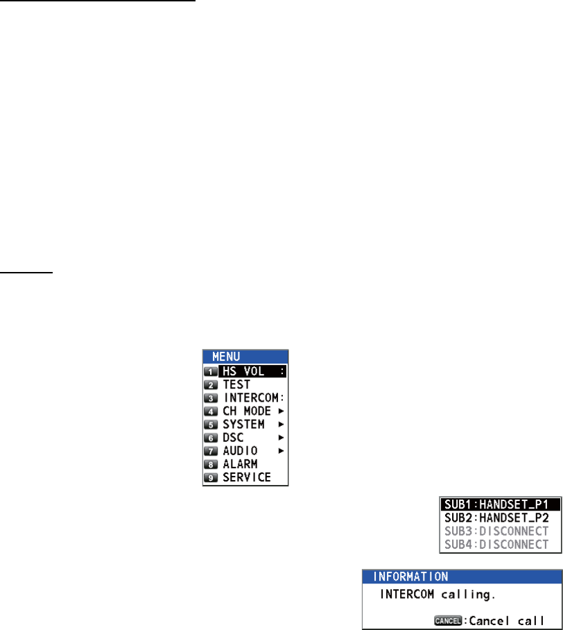
1.13 Intercom
The built-in intercom permits voice communications between two terminals.
Calling
You can call over the intercom in on or off hook condition.
1. Press the MENU key to open the [MENU] screen.
2. Rotate the CHANNEL/ENTER knob to select [INTERCOM]
then push the knob.
3. Rotate the CHANNEL/ENTER knob to select
the called party’s terminal then push the knob.
The called party’s terminal rings.
To cancel calling, press the CANCEL key.
1. OPERATIONAL OVERVIEW
1-9
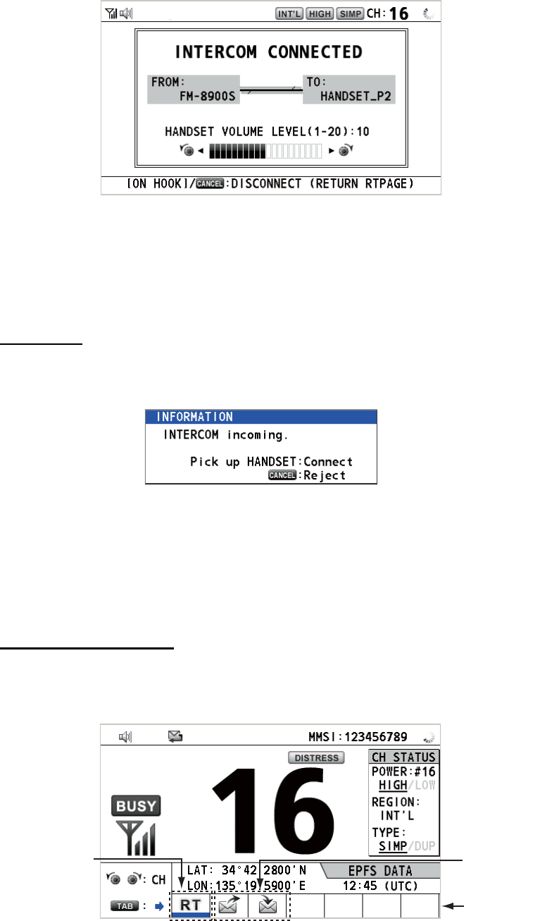
4. When the called party picks up their handset, the following screen appears.
Start communications.
Note: You do not have to press the PTT switch to communicate.
5. If needed, adjust the handset volume by rotating the CHANNEL/ENTER knob.
6. Hang up the handset or press the CANCEL key to turn the intercom off. The last-
used screen appears.
Answering
1. The terminal rings and the following screen appears. To cancel reply, press the
CANCEL key.
2. Pick up the handset to start communications.
3. Hang up the handset or press the CANCEL key to turn the intercom off. The last-
used screen appears.
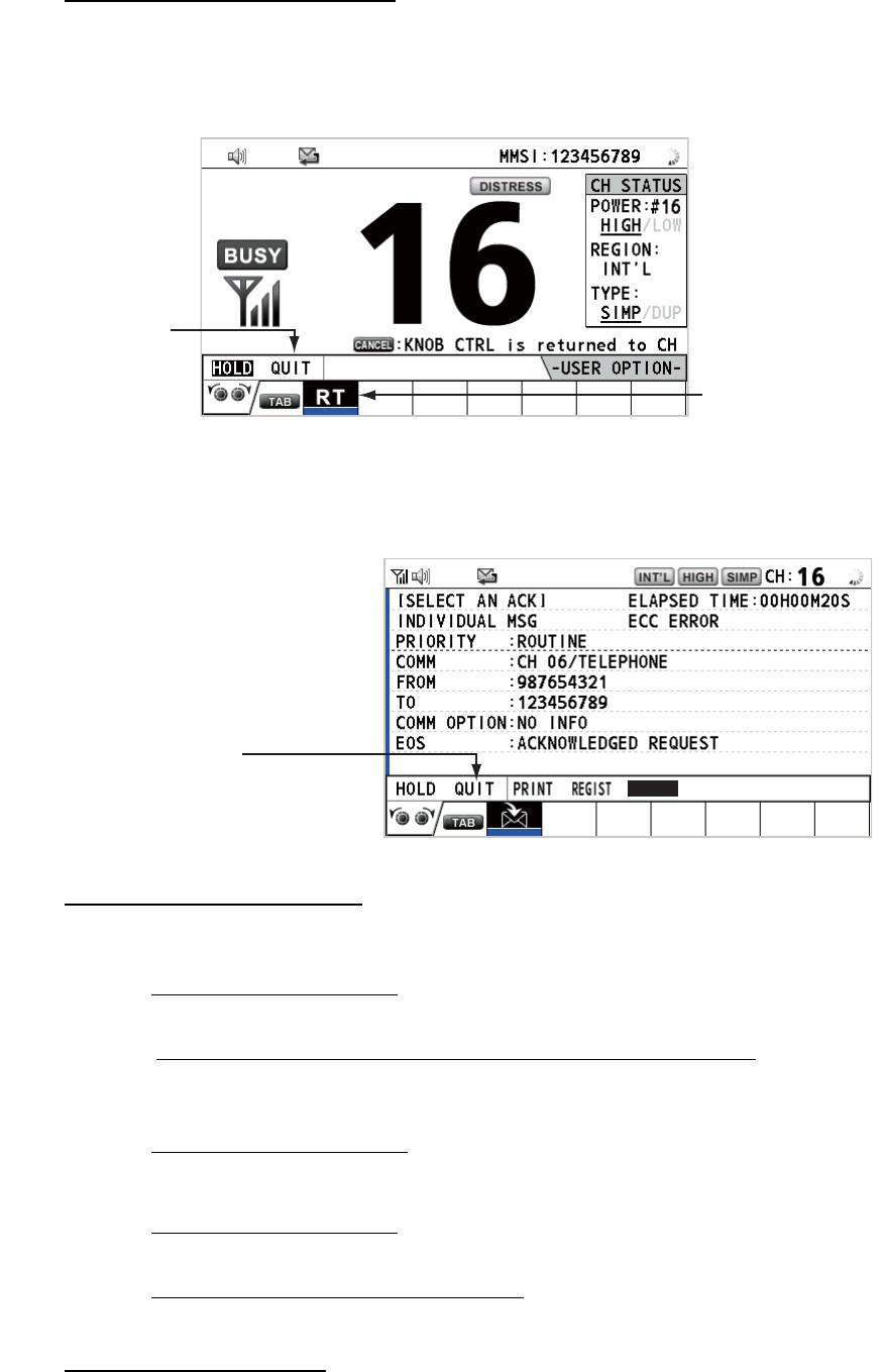
1.14 Operation of Session
Description of session
There are two types of sessions: RT session and DSC session. When a session starts,
the applicable icon for the session appears in the tab area.
RT session DSC sessions
Tab area
1. OPERATIONAL OVERVIEW
1-10
How to finish a single session
RT session
1. Press the TAB key to select the RT icon in the tab area.
2. Rotate the CHANNEL/ENTER knob to select [QUIT] then push the knob.
DSC session
The cursor is in the tab area when the DSC session starts. Rotate the CHANNEL/EN-
TER knob to select [QUIT] then push the knob.
How to start a new session
When another session is active:
• When sending the distress alert, all sessions except the distress alert TX session
automatically close then the distress alert TX session starts.
• When doing an RT session or sending a non-distress DSC message, the currently
active session is put on hold then the RT session or non-distress DSC message TX
session starts.
• When receiving a DSC message, its session is put on hold.
When no other session is active:
• When sending the distress alert, all sessions except the distress alert TX session
automatically close then the distress alert TX session starts.
• When sending a non-distress DSC message, its session becomes the active ses-
sion.
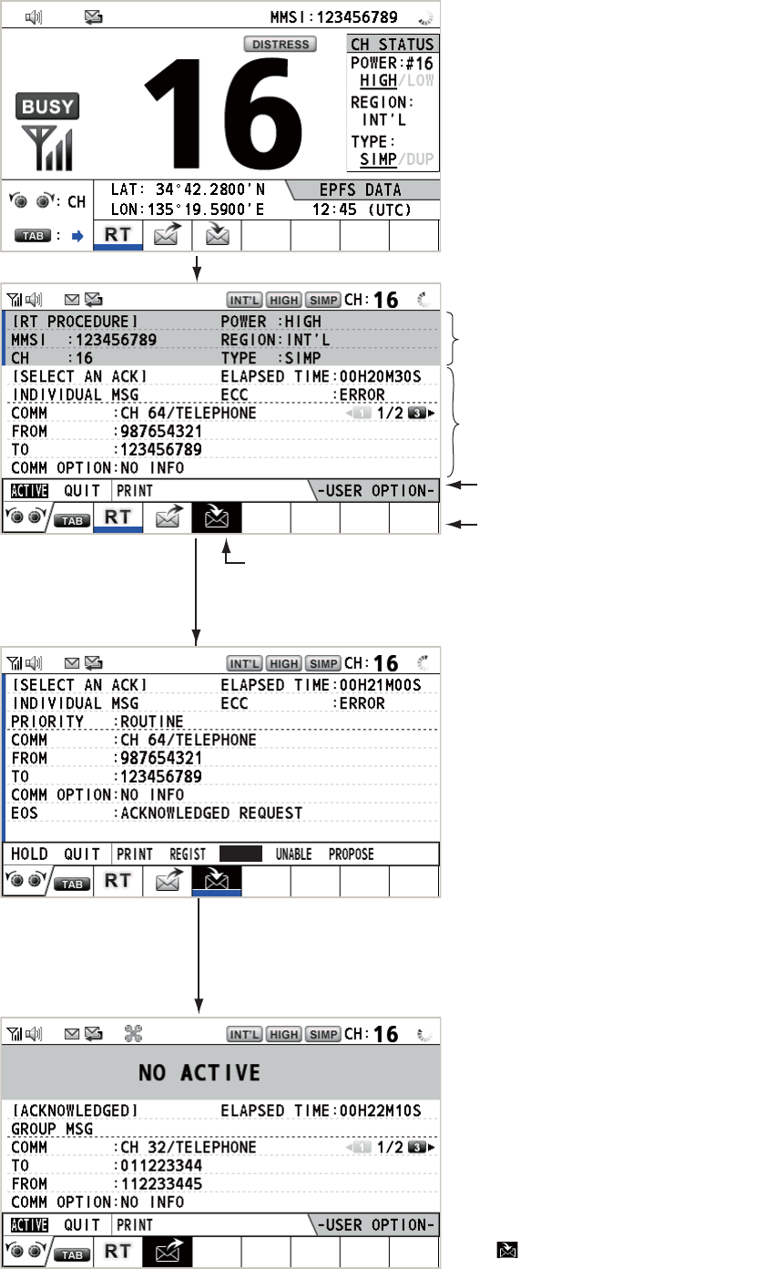
How to switch sessions
When one session is active and another message arrives, a new session for the re-
ceived message does not start automatically. Only one session can be active. For ex-
Step 1: Press the
TAB key to select
the RT icon.
Step 2: Rotate the
CHANNEL/ENTER
knob to select [QUIT]
then push the knob.
Rotate the CHANNEL/ENTER
knob to select [QUIT] then
push the knob.
ACCEPT UNABLE PROPOSE
1. OPERATIONAL OVERVIEW
1-11
ample, when you are transmitting a DSC message and another message arrives, the
indication [ACTIVE] appears to indicate the start of a new session.
Press the TAB key to move the cursor to the tab area.
Only the screen for the selected
session appears.
To finish this session, rotate the CHANNEL/ENTER knob to select
[QUIT] then push the knob.
The icon disappears.
Note: When waiting for the ACK, that is, the session is in progress,
the confirmation message appears. Rotate the CHANNEL/ENTER
knob to select [Yes] or [No] then push the knob.
To select a session, press the TAB key. The cursor is here.
Information for the session
selected by cursor.
With [ACTIVE] selected, push the CHANNEL/ENTER knob to
switch the active session. To switch the option for the session
([ACTIVE], [QUIT], [PRINT]), rotate the CHANNEL/ENTER knob.
User options area
Tab area
Information for the session
underlined in blue (RT in
this case)
ACCEPT
1. OPERATIONAL OVERVIEW
1-12
How to close a session
To manually close a session, select it with the TAB key. Rotate the CHANNEL/EN-
TER knob to select [QUIT] in the user options area then push the knob. The session
icon disappears from the tab area.
When there is no operation for the time specified (see section 5.8), the inactive ses-
sion is automatically closed.
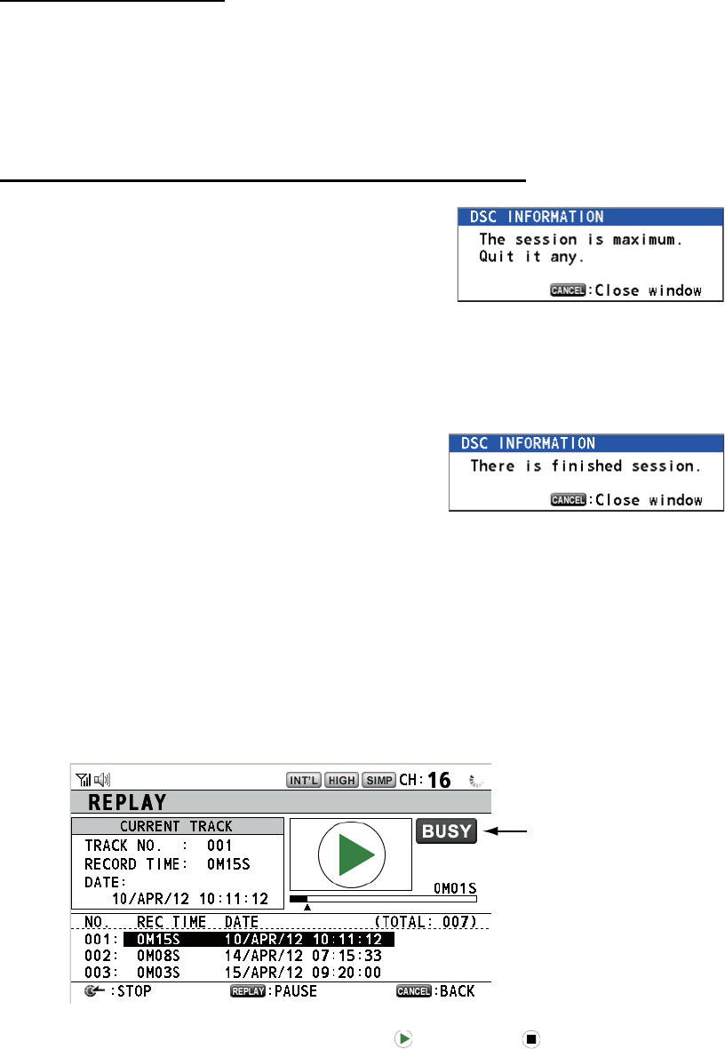
Processing when the number of sessions is maximum
A maximum of seven sessions can be displayed in
the tab area. If a seventh session starts, the mes-
sage as shown in the right figure appears on the
screen. Press the CANCEL key to close the mes-
sage. Close a session to make space for the new
session.
If the eighth session is for sending a distress alert, all sessions except that session
automatically close, and the session starts.
If the eighth session is for receiving DSC message,
the lowest-priority session automatically closes
and the message as shown in the right figure ap-
pears. Press the CANCEL key to close the mes-
sage.
1.15 Replay Function
You can replay a recorded voice, which has been received recently, for a total of 120
seconds. The recorded voices are saved in this equipment with the channel informa-
tion, and deleted when turning the power off.
To replay the recorded voice, press the REPLAY key.
When the replaying is finished, the indication changes to .
To change the track number, rotate the CHANNEL/ENTER knob to select the track
number desired then push the knob to replay the selected data.
To stop the replaying and close the screen in the middle, press the CANCEL key. Al-
so, you can stop the replaying with the CHANNEL/ENTER knob. In this case, the [RE-
PLAY] screen does not close.
Note: When the time limit (120 seconds) has passed, the recorded data is deleted per
track in earliest to latest order.
Appears only when
the squelch opens.
2-1
2. DSC OVERVIEW
2.1 What is DSC?
DSC is an acronym meaning Digital Selective Calling. It is a digital distress and gen-
eral calling system in the VHF band used by ships for transmitting distress alerts and
general calls and by coast stations for transmitting the associated acknowledgements.
For DSC distress, safety and urgency callings in the VHF band, the channel is 70.
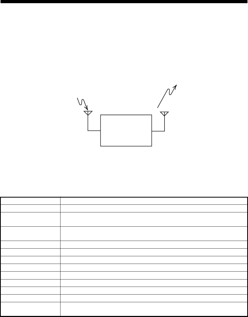
2.2 DSC Messages
DSC calls are roughly divided in two groups: distress messages and general (safety,
urgency and routine) messages. Below are the types of DSC messages.
*SPECIAL MSG: To send these messages, set [SPECIAL MSG] to [ABLE]. See
section 5.17.
Call Description
DISTRESS ALERT Your ship sends distress message.
DISTRESS RELAY
ALL
Your ship relays distress call to all ships.
DISTRESS RELAY
INDIVIDUAL
Your ship relays distress call to a coast station or all ships.
MEDICAL MSG* Inform areas that your ship is carrying medical supplies.
NEUTRAL MSG* Inform areas that your ship is not a participant in armed conflict.
INDIVIDUAL MSG Call to a specific address.
PSTN MSG Call over Public Switched Telephone Network (PSTN).
TEST MSG Send test signal to a station to test your station's functionality.
GROUP MSG Call to a specific group.
ALL SHIPS MSG Call to all ships.
POSITION MSG Your ship requests position of other ships.
POLLING MSG Confirm if your ship is within communicating range with other ships. (Re-
ceive and answer only)
TRANSCEIVER
UNIT
Distress, Safety, Urgency and Routine DSC Calls
Distress, Safety, Urgency and Routine DSC Calls
ANT
CH70 RX ANT

2. DSC OVERVIEW
2-2
Contents of a DSC call
• Calling category
DISTRESS: DISTRESS ALERT, DISTRESS RELAY ALL, DISTRESS RELAY IN-
DIVIDUAL, DISTRESS RELAY AREA (Received only), DISTRESS ACK
GENERAL: MEDICAL MSG, NEUTRAL MSG, INDIVIDUAL MSG, PSTN MSG,
TEST MSG, GROUP MSG, ALL SHIPS MSG, POSITION MSG, POLLING MSG
• Station ID (MMSI)
Your ship ID and sending station ID. Coast station ID begins with 00; Group ID be-
gins with 0.
• Priority
Distress: Grave and imminent danger and request immediate assistance.
Urgency: A calling station has a very urgent call to transmit concerning safety of
ship, aircraft or other vehicle or safety of person.
Safety: A station is about to transmit a call containing an important navigational or
meteorological warning.
Routine: General calling
• Communication mode
TELEPHONE: Telephone (F3E/G3E) by VHF radiotelephone
• Communication channel
Working frequency channel used to call by telephone. The sending station may
have the receiving station (ship or coast station) assign the frequency channel to
use.
• Position
Position can be automatically or manually set.
• End code
The end of a DSC call is indicated with "EOS" (acknowledgement, acknowledge-
ment required, no acknowledgement required).
2.3 Audio Alarms
When you receive a distress alert or general call addressed to your ship, the audio and
visual alarms are released. The audio alarm can be silenced with the CANCEL key.
Alarm When Frequency (interval)
Count
alarm
Counting down the time remaining before the distress
alert is transmitted.
2000 Hz (500 ms) → silent
(500 ms); three times
Distress
RX alarm
The following sessions are received:
distress alert, relay individual, relay area, or relay all.
2200 Hz (250 ms) → 1300 Hz
(250 ms); repetition
Distress
TX alarm
Sending or resending the distress alert. 2200 Hz (2000 ms); once
Distress
ACK
alarm
The following sessions are received or received then ac-
knowledged:
distress ACK, distress ACK (cancel ACK), relay individ-
ual ACK, or relay all ACK.
2200 Hz (500 ms) → 1300 Hz
(500 ms); repetition
Urgency
alarm
The following urgency sessions are received:
all ships, neutral, medical, or individual.
2200 Hz (250 ms) → silent
(250 ms); repetition
Urgency
ACK
alarm
The sessions for urgency individual ACK are received
then acknowledged. The sessions for delayed ACK are
received.
2200 Hz (500 ms) → silent
(500 ms); repetition
2. DSC OVERVIEW
2-3
2.4 Description of Call Screens
This section provides the information necessary for interpreting the receive and send
call screens.
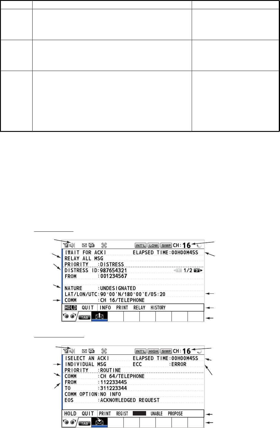
2.4.1 RX calls
Below are sample distress relay and individual RX call screens. The contents of other
types of RX calls are similar to that of the individual call.
Distress relay
Individual RX call
Ordinary
alarm
The following sessions are received:
• Safety: all ships, individual, position, or test.
• Routine: individual, group, polling, or PSTN.
The following set is repeated:
750 Hz (50 ms) and 650 Hz
(50 ms); ten times → silent
(2000 ms); once
Ordinary
ACK
alarm
The following sessions are received then acknowledged:
• Safety: individual ACK, position ACK, test ACK.
• Routine: individual ACK.
The sessions for delayed ACK are received.
The following set is repeated:
750 Hz (50 ms) and 650 Hz
(50 ms); ten times → silent
(2000 ms); once
Self ter-
minating
alarm
• There are the related sessions for call messages.
• The related sessions for ACK messages were already
acknowledged.
• Sending the individual unable auto ACK or PSTN un-
able auto ACK.
• The following sessions are received:
relay area (duplicate), relay all (duplicate), or PSTN
end of call ACK.
1300 Hz (100 ms) → silent
(300 ms) → 1300 Hz (100 ms)
→ silent (50 ms) → 1300 Hz
(100 ms)
Alarm When Frequency (interval)
Working channel
to use
Call type
Elapsed time since
distress alert received
ID No. (MMSI)
of ship in
distress
Communication
mode and
suggested
channel
Available user options
Session in progress
Speaker icon
Position of ship
in distress
Nature of
distress
Working channel
to use
Speaker icon
Elapsed time since
call received
ID No. (MMSI)
of ship
sending this
message
Available user options
Communication
mode
Session in progress
Call type
Appears when ECC
is NG.
ACCEPT
2. DSC OVERVIEW
2-4
The characters "*", "-" appear on the DSC receiving screen in the following conditions:
• "*" indicates a corrupt character in received data.
• "-" indicates missing digits after decimal point when receiving position data with no
info for expansion (expansion: digits after decimal point).
Examples:
1) When receiving position data without expansion, the indication is
"LAT: 12°34’N".
2) When receiving position data with expansion, the indication is
"LAT: 12°34,5678’N".
3) When receiving position data with no info for expansion, the indication is
"LAT: 12°34,----’N".
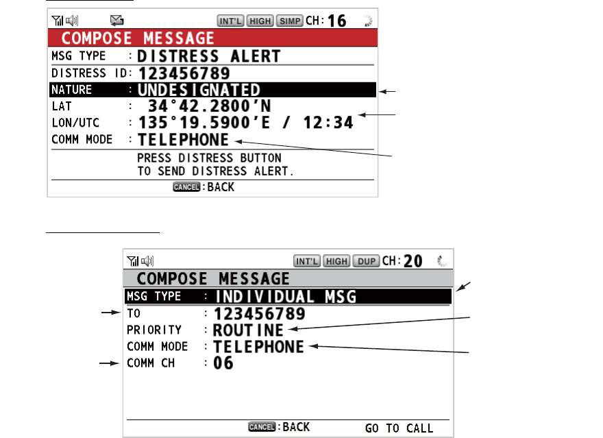
2.4.2 TX calls
Below are sample distress alert and individual TX call screens. The contents of other
types of TX calls are similar to that of the individual call.
Distress alert
Individual TX call
Nature of Distress
Position of ship in distress (your
ship) and time of distress position
Communication mode
Message type
(Individual)
ID No. of station
where message
is to be sent
Priority (Routine,
Safety, Urgency)
Communication
mode
Communication
channel
3-1
3. DSC DISTRESS OPERATIONS
Distress operation overview
1. Press the DISTRESS key.
2. Wait for the distress alert acknowledgement.
3. Communicate with the coast station.
3.1 How to Send a Distress Alert
GMDSS ships carry a DSC terminal with which to transmit the distress alert in the
event of a life-endangering situation. A coast station receives the distress alert and
sends the distress alert acknowledge call to the ship in distress. Then, voice commu-
nication between the ship in distress and coast station begins. Transmission of the dis-
tress alert and receiving of the distress alert acknowledgement are completely
automatic - simply press the DISTRESS key to initiate the sequence.
Note: After sending the distress alert, the terminal which its PTT switch is pressed first
has top priority.
3.1.1 How to send a distress alert by DISTRESS key with distress in-
formation not edited
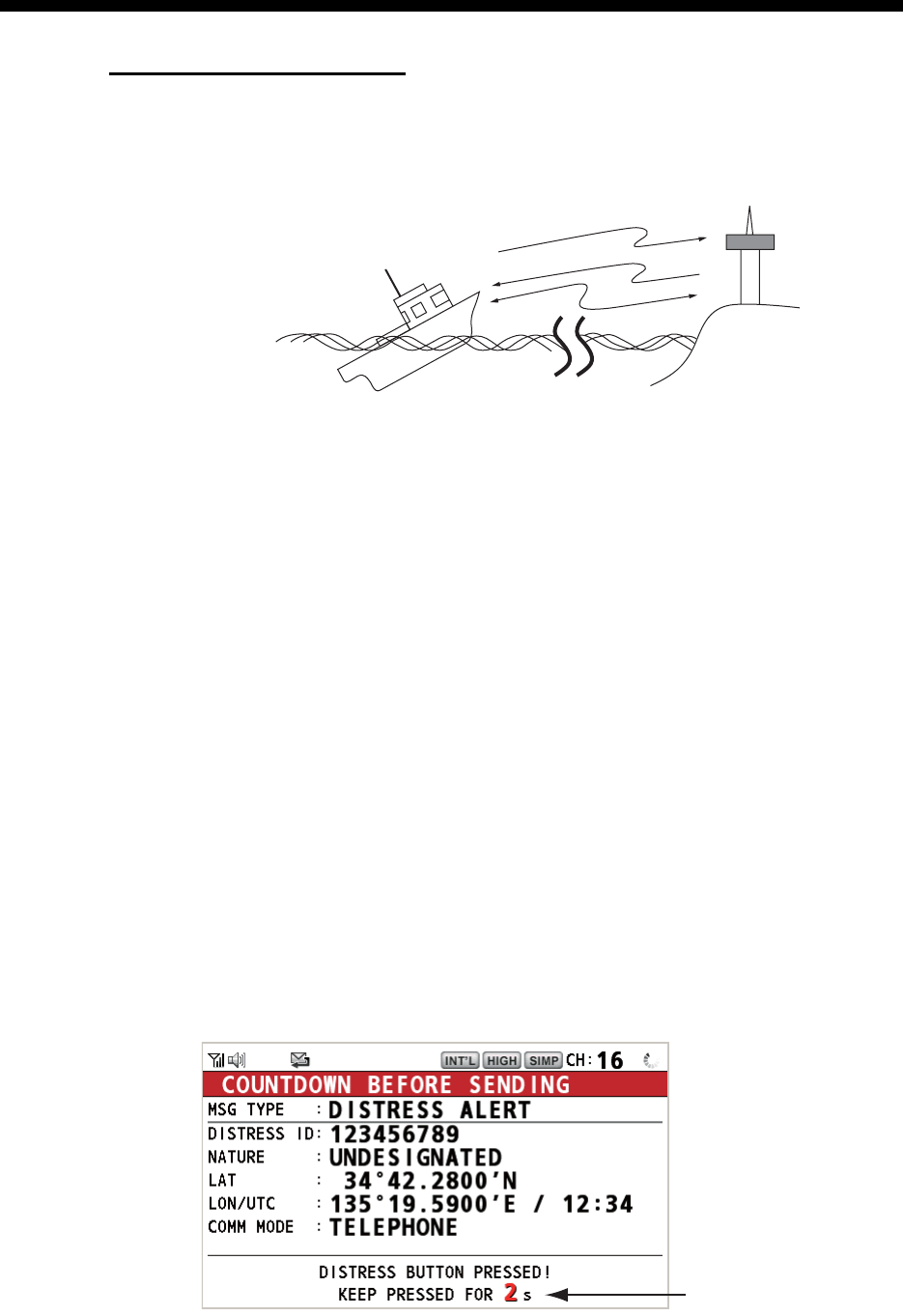
1. Open the DISTRESS key cover then press and hold the DISTRESS key for four
seconds. The audio alarm sounds while pressing the key, and the key flashes in
red. The countdown message appears on the screen while pressing the DIS-
TRESS key (3s → 2s → 1s → 0s).
(3)
(2)
(1)
Ship in distress
(Your ship)
(1) Ship in distress sends Distress Alert.
(2) Coast station sends distress acknowledgement (DIST ACK).
(3) Voice communication between ship in distress and coast station.
Coast
station
Countdown message
3. DSC DISTRESS OPERATIONS
3-2
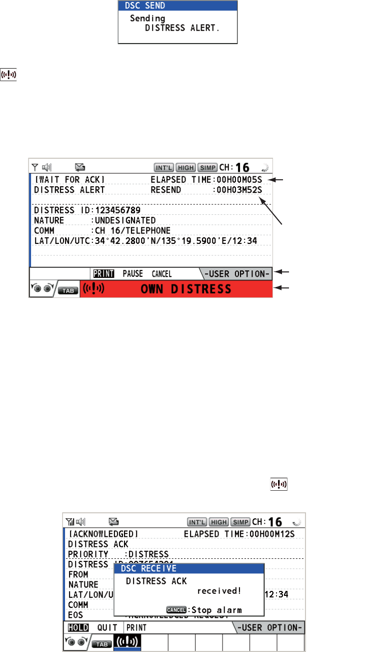
When the countdown shows 0s, the distress alert is sent. The audio alarm sounds
for two seconds and the message "Sending DISTRESS ALERT." appears.
The DISTRESS key lights in red and only the icon for DISTRESS transmission
( ) is displayed in the tab area.
After the distress alert has been sent, the screen changes as below. Wait to re-
ceive the distress acknowledge call from a coast station. The elapsed time since
transmission is displayed. At this time, the icons for other DSC received messag-
es except the distress alert acknowledge call are not displayed. You can only con-
firm them in the log.
Note: If you do not receive the distress alert acknowledge call, the equipment au-
tomatically re-transmits the distress alert after 3 min 30 seconds to 4 min 30 sec-
onds. The equipment then awaits the distress alert acknowledge call. This is
repeated until the distress alert is acknowledged.
You can temporarily stop the countdown for next retransmission by selecting
[PAUSE] in the user options area. The [PAUSE] indication changes to [START]
and [PAUSE] is displayed instead of the countdown indication. To restart, select
[START]. The countdown restarts and the [START] indication changes to
[PAUSE].
Also, you can re-send the distress alert manually by pressing and holding the DIS-
TRESS key for four seconds.
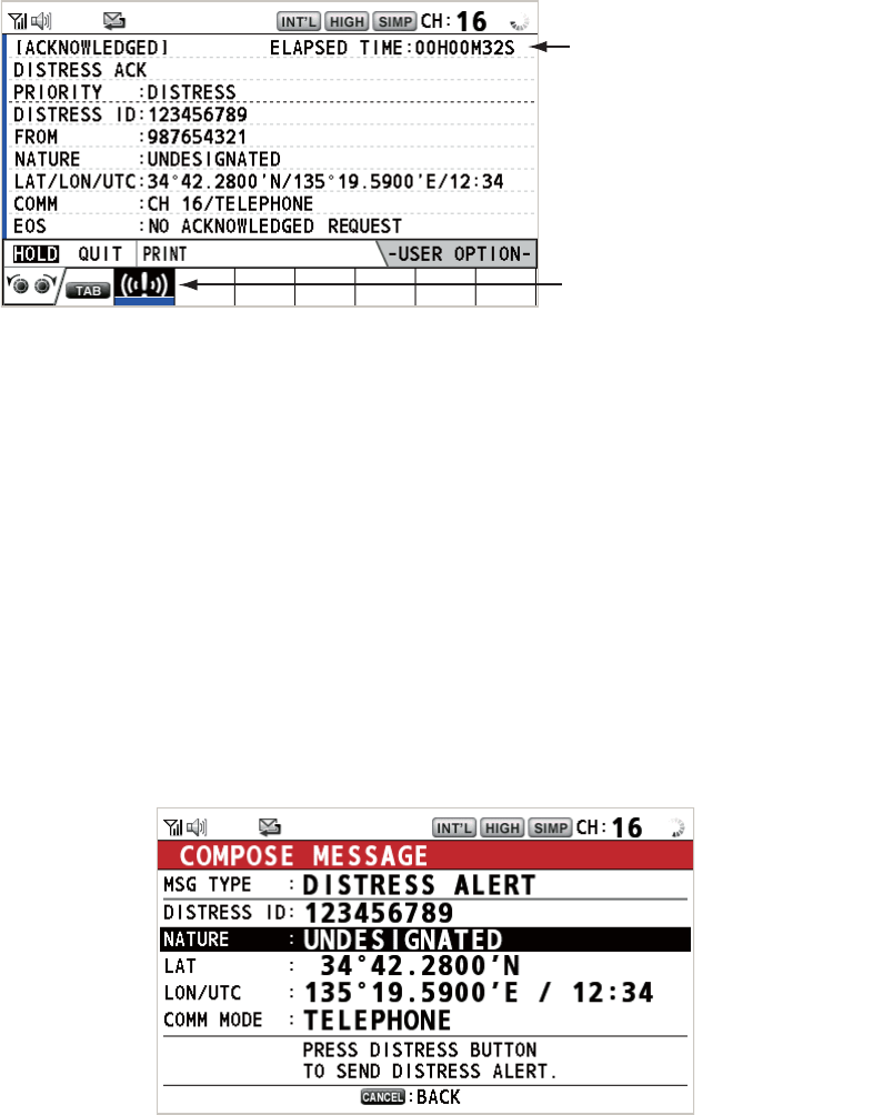
When the distress acknowledge call is received, the audio alarm sounds, the LED
flashes in red, and the icon for DISTRESS transmission ( ) appears. The
screen changes as below.
Elapsed time
since distress
alert transmission
User options area
Tab area
Countdown until
next retransmission
3. DSC DISTRESS OPERATIONS
3-3
2. Press the CANCEL key to silence the audio alarm. Then, the LED stops flashing,
and the pop-up message disappears.
3. Communicate with the coast station via radiotelephone, following the instructions
below.
a) Say “MAYDAY” three times.
b) Say “This is ...” name of your ship and call sign three times.
c) Give nature of distress and assistance needed.
d) Give description of your ship (type, color, number of persons onboard, etc.).
3.1.2 How to send a distress alert by DISTRESS key with distress in-
formation edited
If you have a time to prepare the distress information, send the distress alert as fol-
lows:
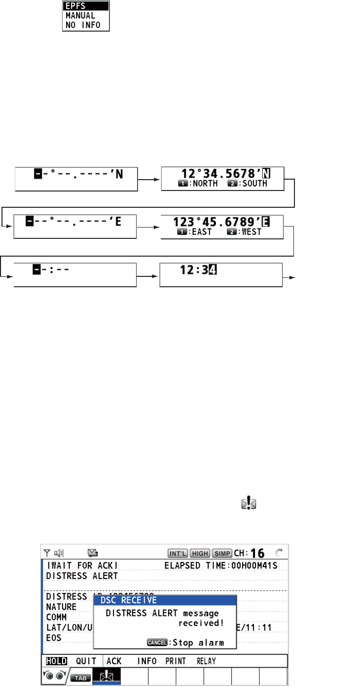
1. Press the DISTRESS MSG key to display the following screen.
2. With [NATURE] selected, push the CHANNEL/ENTER knob.
3. Rotate the CHANNEL/ENTER knob to select the nature of distress, among the
following 11 selections, then push the knob.
• UNDESIGNATED • FIRE • FLOODING
• COLLISION • GROUNDING • LISTING
• SINKING • DISABLED&ADR(IFT) • ABANDONING
• PIRACY • MAN OVERBOARD
Count up the elasped time
after receiving distress
acknowledge call.
Icon for DISTRESS transmission
3. DSC DISTRESS OPERATIONS
3-4
4. With [LAT] and [LON/UTC] selected, push the CHANNEL/ENTER knob.
[EPFS]: The position information from EPFS is automatically shown.
[MANUAL]: Input your position manually.
[NO INFO]: No information.
5. Rotate the CHANNEL/ENTER knob to select [EPFS], [MANUAL] or [NO INFO]
then push the knob. For [MANUAL], go to step 6. For others, go to step 7.
6. Use the numeric keys to enter latitude, longitude and UTC time. (If necessary,
switch coordinates: 1 key to switch to North (East for longitude); 2 key to switch to
South (West for longitude).) Push the CHANNEL/ENTER knob.
7. Press and hold the DISTRESS key for four seconds to send the distress alert. The
audio alarm sounds while pressing the key, and the key flashes in red. The count-
down message appears on the screen while pressing the DISTRESS key (3s →
2s → 1s → 0s) (refer to the illustration at step 1 in paragraph 3.1.1). When the
countdown shows 0s, the distress alert is sent. The audio alarm sounds for two
seconds and the message "Sending DISTRESS ALERT." appears.
8. When the distress acknowledge call is received, use the telephone to communi-
cate with the coast station referring to step 3 in paragraph 3.1.1.
3.2 How to Receive a Distress Alert
When you receive a distress alert from a ship in distress, the audio alarm sounds and
the LED flashes in red. The icon for DISTRESS receiving ( ) appears in the tab area
and the pop-up message "DISTRESS ALERT message received! [CANCEL]: Stop
alarm" appears on the screen.
The option which you last-selected
is highlighted.
Latitude setting window
Longitude setting window
Push the
CHANNEL/
ENTER knob.
UTC setting window
Push the
CHANNEL/
ENTER knob.
Push the
CHANNEL/
ENTER knob.
HISTORY
3. DSC DISTRESS OPERATIONS
3-5
Press the CANCEL key to silence the audio alarm. Wait for the distress acknowledge
call from a coast station. If you do not receive the distress acknowledge call from a
coast station, which usually takes about five minutes from the time of receiving a dis-
tress alert, follow the flow charts in this section to determine your action.
Note: An asterisk (*) appearing in a distress alert message indicates an error at the
asterisk’s location.
In no case is a ship permitted to transmit a DSC distress relay call upon receipt of a
DSC distress alert on VHF channel 70.
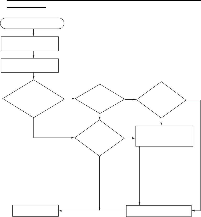
Flow chart for determining if you should/should not transmit a distress ac-
knowledge call
DSC distress alert received.
Press the CANCEL key
to silence alarm.
Listen on CH16 for
5 minutes.
Did you receive
acknowledge from
CS and/or RCC?
No No No
Yes
Yes Yes
Yes
No
Is distress traffic
in progress?
Is the DSC
distress call
continuing?
Is your ship
able to aid
ship in
distress?
Acknowledge the alert by
radiotelephone to the ship
in distress on VHF CH16.
Inform CS and/or RCC.
Enter details in log.
CS = Coast Station
RCC = Rescue Coordination Center
1. Say "MAYDAY" once.
2. Say ID number of ship in
distress three times.
3. Say "This is" (your ship's
name) once.
4. Say ID number of your
ship three times.
5. Say "Received MAYDAY"
once.
3. DSC DISTRESS OPERATIONS
3-6
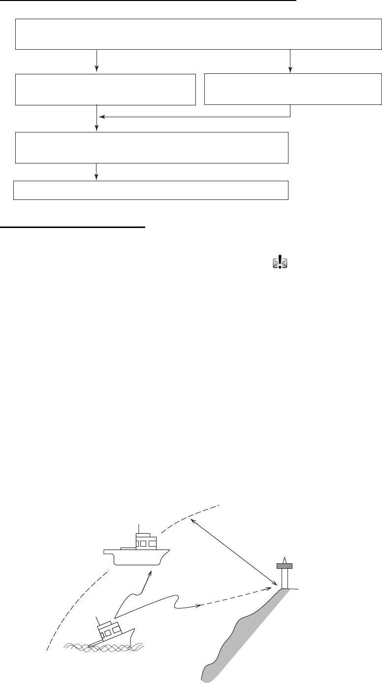
How to transmit a distress acknowledge call over CH16
Procedure when in area A1
When you receive a distress alert from a ship in distress, the audio alarm sounds and
the LED flashes in red. The icon for DISTRESS receiving ( ) appears in the tab area
and the pop-up message "DISTRESS ALERT message received! [CANCEL]: Stop
alarm" appears on the screen.
Press the CANCEL key to silence the audio alarm. Wait for the distress acknowledge
call from a coast station. If you do not receive the distress acknowledge call from a
coast station, which usually takes about five minutes from the time of receiving a dis-
tress alert, follow the flow charts on page 3-5.
If further DSC alerts are received from the same source and the ship in distress is be-
yond doubt in the vicinity, a DSC acknowledgement may, after consultation with a
Rescue Coordination Center (RCC) or Coast Station, be sent to terminate the distress
call.
Note 1: An asterisk (*) appearing in a distress alert message indicates an error at the
asterisk’s location.
Note 2: Do not send the distress acknowledge call in response to receipt of distress
alert having the nature of distress as "EPIRB emission".
Select VHF CH16 and transmit the distress acknowledge call to
the ship in distress.
Relay the distress alert to a coast station over DSC.
Follow the instructions of the coast station.
Transmit the distress acknowledge call
to the ship in distress over DSC CH70. Communicate with the ship in distress.
No reply Reply received
Begin search and rescue operation for the ship in distress.
About 20 to 30 miles
(Sea area A1)
Your ship
Coast station
Distress alert
transmission
Ship in distress
3. DSC DISTRESS OPERATIONS
3-7
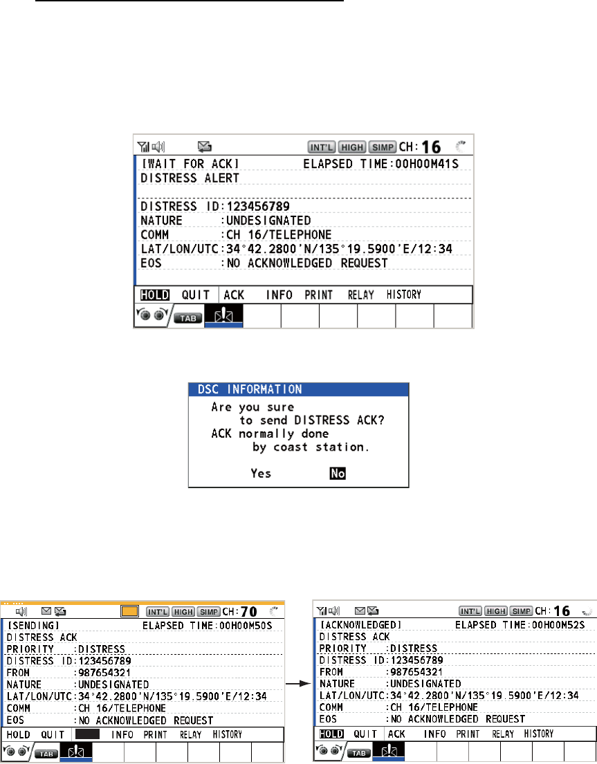
How to send a distress acknowledge call
When you receive a distress alert from a ship in distress, the audio alarm sounds and
the LED flashes in red. If your ship meets the requirements necessary to transmit the
distress acknowledge call, do the following:
1. Press the CANCEL key to silence the audio alarm and stop the flashing of the
LED.
2. Rotate the CHANNEL/ENTER knob to select [ACK] in the user options area then
push the knob. The following message appears on the screen.
3. If you do not receive the distress acknowledge call from a coast station within five
minutes and your ship meets requirements for transmitting the distress acknowl-
edge call, rotate the CHANNEL/ENTER knob to select [Yes] then push the knob
to send the distress acknowledge call to the ship in distress. The screen changes
as below.
Begin search and rescue operations for the ship in distress, communicating with the
ship over CH16 (automatically set). Relay distress alert to a coast station by DSC fol-
lowing the instruction in the next section. Finally, follow the instructions of the coast
station.
TX
ACK
3. DSC DISTRESS OPERATIONS
3-8
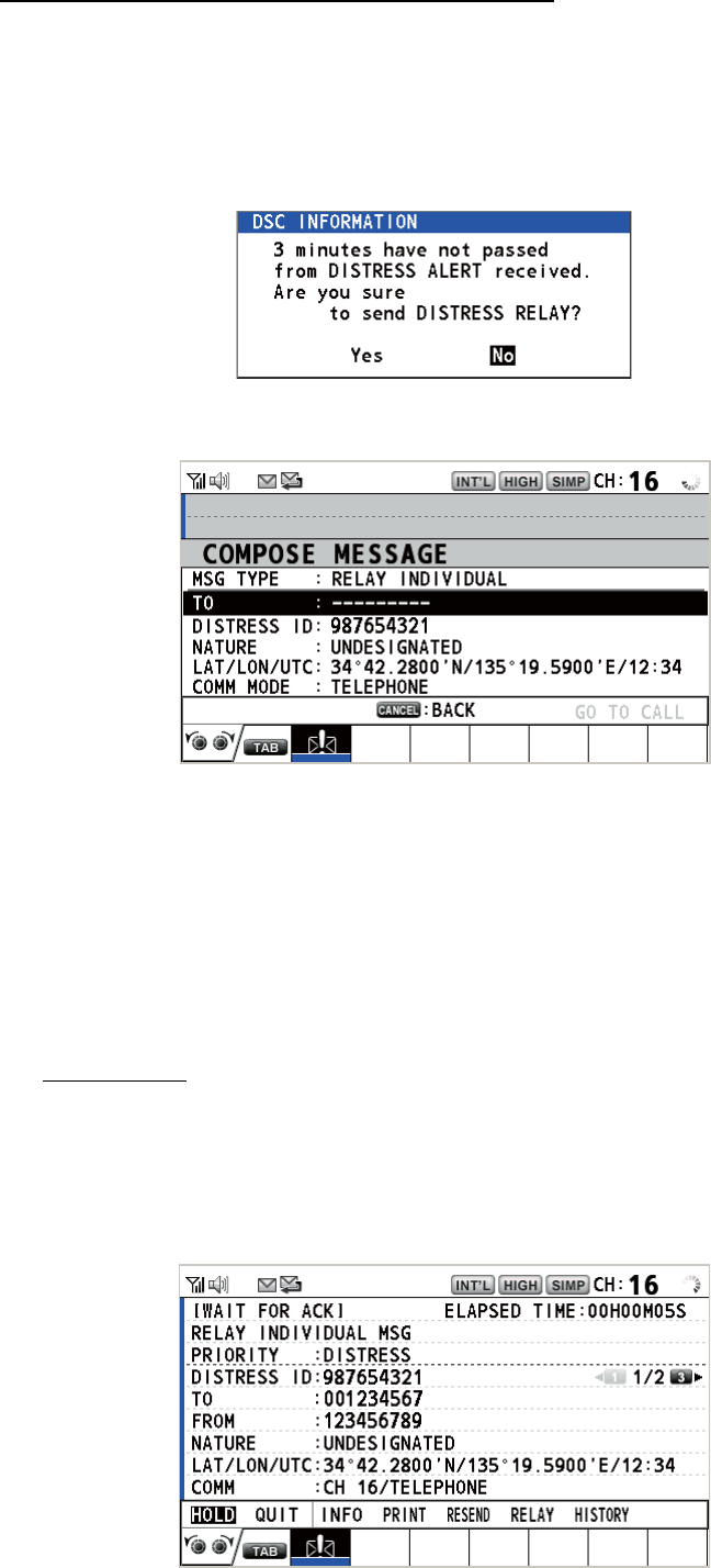
How to send a distress relay to a coast station
You can send the distress relay to a coast station from the receiving screen for the
distress alert.
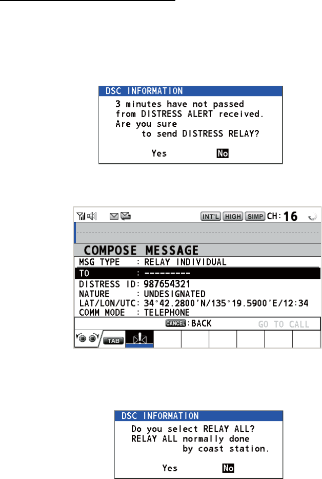
1. Rotate the CHANNEL/ENTER knob to select [RELAY] in the user options area
then push the knob. If three minutes have not passed from the time the distress
alert was received, the following message appears.
2. Rotate the CHANNEL/ENTER knob to select [Yes] then push the knob to open
the composing screen for the distress relay individual.
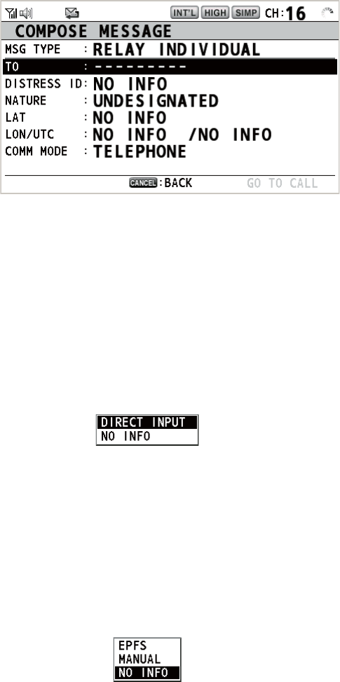
3. With [TO] selected, push the CHANNEL/ENTER knob.
4. Rotate the CHANNEL/ENTER knob to select [DIRECT INPUT], [ADDRESS
BOOK DATA] or [AIS TARGET DATA] then push the knob.
[DIRECT INPUT]: Enter the MMSI, where to send the distress relay, with the nu-
meric keys then push the CHANNEL/ENTER knob.
[ADDRESS BOOK DATA]: Select an MMSI from the [ADDRESS BOOK] (see
section 5.13) then push the CHANNEL/ENTER knob.
[AIS TARGET DATA]: Select an MMSI from the [AIS TARGET LIST] then push
the CHANNEL/ENTER knob.
AIS target list
If an AIS transponder is connected to the radiotelephone, you can select a MMSI
from the [AIS TARGET LIST].
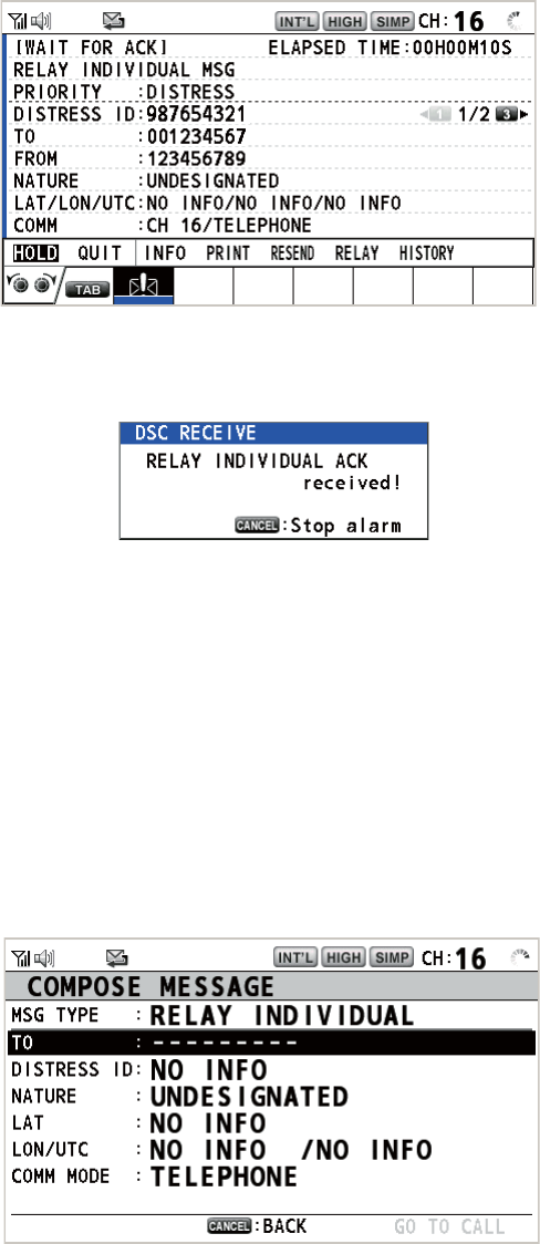
5. With [GO TO CALL] selected, push the CHANNEL/ENTER knob. The distress re-
lay is transmitted. After transmitting, the WAIT FOR ACK screen appears. The
elapsed time since transmitting is displayed.
[
W
A
I
T F
OR
A
CK ]
D
I
STRESS ALERT
ELAPSED
T
I
ME :
00
H
01
M
15
S
3. DSC DISTRESS OPERATIONS
3-9
How to send a distress relay all
You can send the distress relay all from the receiving screen for the distress alert.
1. Rotate the CHANNEL/ENTER knob to select [RELAY] in the user options area
then push the knob. If three minutes have not passed from the distress alert re-
ceived, the following message appears.
2. Rotate the CHANNEL/ENTER knob to select [Yes] then push the knob to open
the composing screen for the distress relay individual.
3. Rotate the CHANNEL/ENTER knob to select [MSG TYPE] then push the knob.
4. Rotate the CHANNEL/ENTER knob to select [RELAY ALL] then push the knob.
The following message appears.
5. Rotate the CHANNEL/ENTER knob to select [Yes] then push the knob.
6. With [GO TO CALL] selected, push the CHANNEL/ENTER knob. The distress re-
lay is transmitted to all ships.
[
W
A
I
T F
OR
A
CK ]
D
I
STRESS ALERT
ELAPSED
T
I
ME :
00
H
01
M
15
S
3. DSC DISTRESS OPERATIONS
3-10
3.3 How to Send a Distress Relay on Behalf of a Ship
in Distress
3.3.1 How to send a distress relay to a coast station
You can send the distress relay to a coast station on behalf of a ship in distress in the
following cases:
• You are near the ship in distress and the ship in distress cannot transmit the distress
alert.
• When the master or person responsible for your ship considers that further assis-
tance is necessary.
Note: Do not use the DISTRESS key to relay distress.
1. Press the DISTRESS MSG key and the OTHER DSC MSG key simultaneously to
open the composing screen for the distress relay individual.
2. With [TO] selected, push the CHANNEL/ENTER knob.
3. Rotate the CHANNEL/ENTER knob to select [DIRECT INPUT], [ADDRESS
BOOK DATA] or [AIS TARGET DATA] then push the knob.
[DIRECT INPUT]: Enter the MMSI, where to send the distress relay, with the nu-
meric keys then push the CHANNEL/ENTER knob.
[ADDRESS BOOK DATA]: Select an MMSI from the [ADDRESS BOOK] (see
section 5.13) then push the CHANNEL/ENTER knob.
[AIS TARGET DATA]: Select an MMSI from the [AIS TARGET LIST] then push
the CHANNEL/ENTER knob.
4. With [DISTRESS ID] selected, push the CHANNEL/ENTER knob.
5. Rotate the CHANNEL/ENTER knob to select [DIRECT INPUT] or [NO INFO] then
push the knob. For [DIRECT INPUT], go to step 6. For [NO INFO], go to step 7.
6. Enter the ID (MMSI) of the ship in distress with the numeric keys then push the
CHANNEL/ENTER knob.
7. With [NATURE] selected, push the CHANNEL/ENTER knob.
8. Rotate the CHANNEL/ENTER knob to select nature of distress then push the
knob.
9. With [LAT] and [LON/UTC] selected, push the CHANNEL/ENTER knob.
3. DSC DISTRESS OPERATIONS
3-11
10. Rotate the CHANNEL/ENTER knob to select [EPFS], [MANUAL] or [NO INFO]
then push the knob. For [MANUAL], go to step 11. For others, go to step 12.
11. Use the numeric keys to enter latitude and longitude of the ship in distress. (If nec-
essary, switch coordinates: 1 key to switch to North (East); 2 key to switch to
South (West).) Push the CHANNEL/ENTER knob. Also, enter the UTC time then
push the CHANNEL/ENTER knob.
12. With [GO TO CALL] selected, push the CHANNEL/ENTER knob. The distress re-
lay is transmitted. After transmitting, the WAIT FOR ACK screen appears. The
elapsed time since transmitting is displayed.
When you receive the distress relay individual acknowledgement from the coast sta-
tion, the audio alarm sounds and the pop-up message "RELAY INDIVIDUAL ACK re-
ceived! [CANCEL]: Stop alarm" appears.
Press the CANCEL key to silence the alarm and erase the pop-up message. Commu-
nicate with the coast station by telephone. To close the distress receiving session, se-
lect [QUIT] in the user options area then push the CHANNEL/ENTER knob.
3.3.2 How to send a distress relay to all ships
If a coast station directs you to send a distress relay to all ships in your area, follow
the procedure below. Do not transmit a distress relay unless directed to do so by a
coast station.
1. Press the DISTRESS MSG key and the OTHER DSC MSG key simultaneously to
open the composing screen for the distress relay individual.
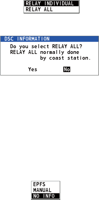
3. DSC DISTRESS OPERATIONS
3-12
2. Rotate the CHANNEL/ENTER knob to select [MSG TYPE] then push the knob.
3. Rotate the CHANNEL/ENTER knob to select [RELAY ALL] then push the knob.
The following message appears.
4. Rotate the CHANNEL/ENTER knob to select [Yes] then push the knob.
5. With [DISTRESS ID] selected, push the CHANNEL/ENTER knob.
6. Rotate the CHANNEL/ENTER knob to select [DIRECT INPUT] or [NO INFO] then
push the knob. For [DIRECT INPUT], go to step 7. For [NO INFO], go to step 8.
7. Enter the ID (MMSI) of the ship in distress with the numeric keys then push the
CHANNEL/ENTER knob.
8. With [NATURE] selected, push the CHANNEL/ENTER knob.
9. Rotate the CHANNEL/ENTER knob to select the nature of distress then push the
knob.
10. With [LAT] and [LON/UTC] selected, push the CHANNEL/ENTER knob.
11. Rotate the CHANNEL/ENTER knob to select [EPFS], [MANUAL] or [NO INFO]
then push the knob. For [MANUAL], go to step 12. For others, go to step 13.
12. Use the numeric keys to enter latitude and longitude of the ship in distress. (If nec-
essary, switch coordinates: 1 key to switch to North (East); 2 key to switch to
South (West).) Push the CHANNEL/ENTER knob. Also, enter the UTC time then
push the CHANNEL/ENTER knob.
13. With [GO TO CALL] selected, push the CHANNEL/ENTER knob. The distress re-
lay is transmitted to all ships.
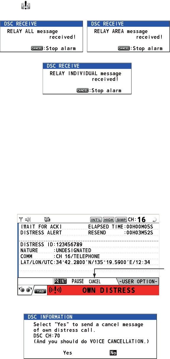
3. DSC DISTRESS OPERATIONS
3-13
3.4 How to Receive a Distress Relay
There are three types of distress relay messages: distress relay for all ships, distress
relay area and distress relay from coast station. When you receive a distress relay
message, continue monitoring CH16. The audio alarm sounds and the LED flashes in
red. The icon ( ) appears in the tab area and the applicable pop-up message ap-
pears on the screen.
1. Press the CANCEL key to silence the audio alarm, stop the flashing of the LED
and erase the pop-up message.
2. Watch CH16.
3.5 How to Cancel the Distress Alert
You can cancel the distress alert while it is being sent or while waiting for its acknowl-
edgement as follows.
1. Rotate the CHANNEL/ENTER knob to select [CANCEL] in the user options area
then push the knob.
The following message appears on the screen.
Distress relay for all ships Distress relay area
Distress relay from coast station
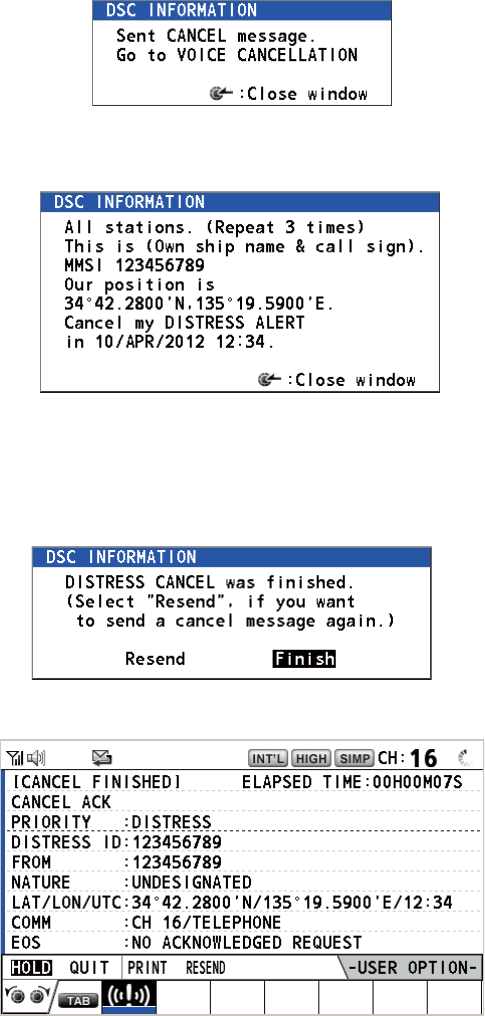
3. DSC DISTRESS OPERATIONS
3-14
2. Rotate the CHANNEL/ENTER knob to select [Yes] then push the knob to cancel
the distress alert over CH70. After transmitting the distress cancel call, the follow-
ing message appears on the screen.
3. Push the CHANNEL/ENTER knob to erase the message. The following message
appears on the screen.
4. Communicate with all ships via radiotelephone referring to the message shown at
step 3.
5. Push the CHANNEL/ENTER knob. The following message appears on the
screen.
6. With [Finish] selected, push the CHANNEL/ENTER knob.
7. Rotate the CHANNEL/ENTER knob to select [QUIT] in the user options area then
push the knob. The RT screen appears.
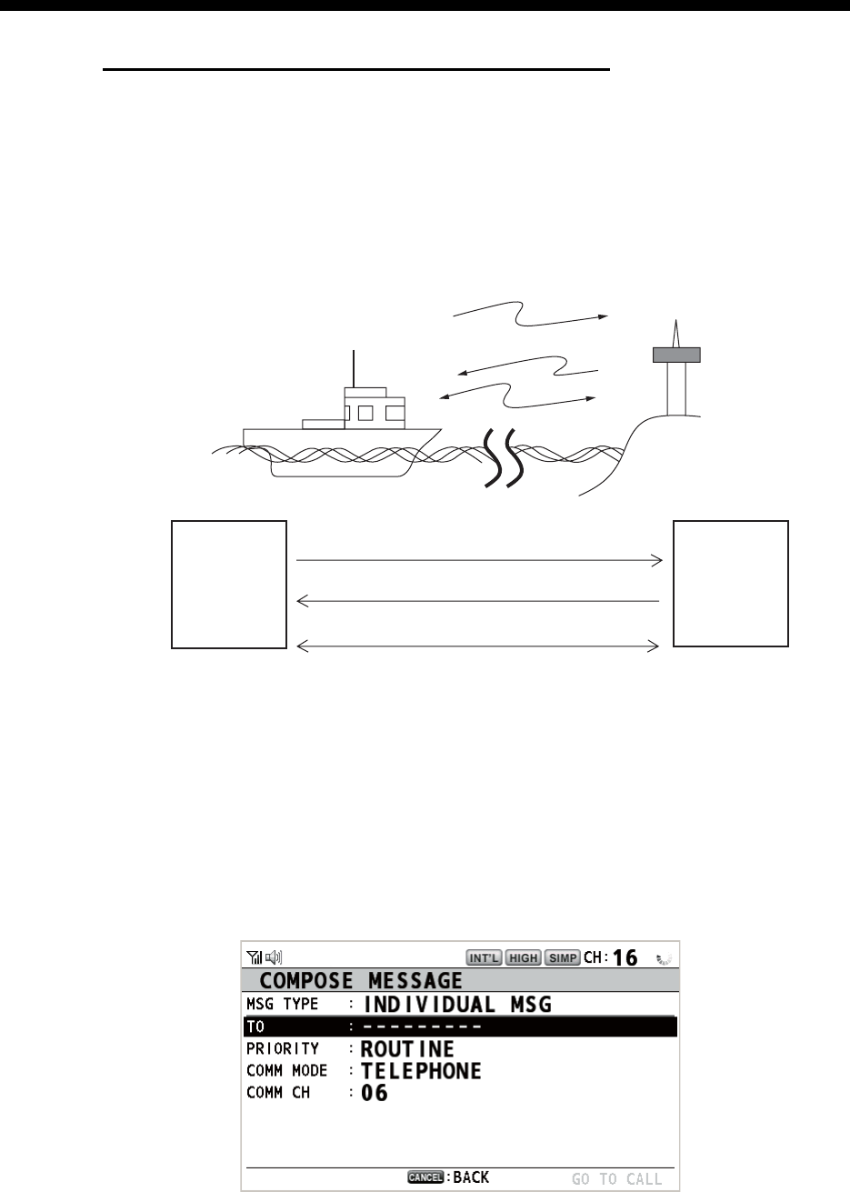
4-1
4. DSC GENERAL MESSAGE
CALLING, RECEIVING
General procedure for non-distress DSC messages
The procedure for sending and receiving non-distress DSC messages is similar
among message types. The following is an example of the sequence for an individual
call.
1. Send the individual message.
2. Wait for the individual message acknowledgement.
3. Start the voice communication.
4.1 Individual Call
The individual call is for calling a specific station. After sending an individual call,
called ACK RQ transmission, wait to receive the acknowledge back (ACK BQ) signal
from the receiving station.
4.1.1 How to send an individual call
1. Press the OTHER DSC MSG key.
(1)
(2)
(3)
Your Ship Coast
Station
(1) DSC Message (Called Acknowledge
Request (ACK RQ) Signal)
(2) Acknowledge Back (ACK BQ) Signal
(3) Voice communication
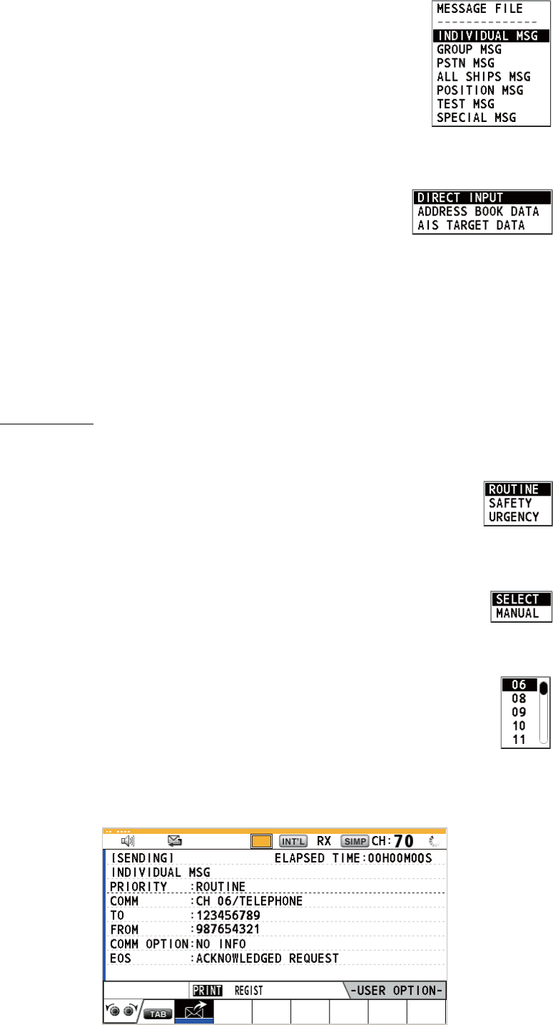
4. DSC GENERAL MESSAGE CALLING, RECEIVING
4-2
2. Rotate the CHANNEL/ENTER knob to select [MSG TYPE]
then push the knob.
3. Rotate the CHANNEL/ENTER knob to select [INDIVIDUAL MSG] then push the
knob.
4. With [TO] selected, push the CHANNEL/ENTER knob.
5. Rotate the CHANNEL/ENTER knob to select [DIRECT INPUT], [ADDRESS
BOOK DATA] or [AIS TARGET DATA] then push the knob.
[DIRECT INPUT]: Enter the MMSI of the station where to send the call then push
the CHANNEL/ENTER knob.
[ADDRESS BOOK DATA]: Select an MMSI from the [ADDRESS BOOK] (see
section 5.13) then push the CHANNEL/ENTER knob.
[AIS TARGET DATA]: Select an MMSI from the [AIS TARGET LIST] then push
the CHANNEL/ENTER knob.
AIS target list
If an AIS transponder is connected to the radiotelephone, you can select an MMSI
from the [AIS TARGET LIST].
6. Rotate the CHANNEL/ENTER knob to select [PRIORITY] then push
the knob.
7. Rotate the CHANNEL/ENTER knob to select [ROUTINE], [SAFETY] or [URGEN-
CY] then push the knob.
8. With [COMM CH] selected, push the CHANNEL/ENTER knob.
9. Rotate the CHANNEL/ENTER knob to select [SELECT] or [MANUAL] then push
the knob.
[SELECT]: The options window as shown in the right figure appears.
Rotate the CHANNEL/ENTER knob to select the channel then push
the knob.
[MANUAL]: Enter the channel then push the CHANNEL/ENTER knob.
10. With [GO TO CALL] selected, push the CHANNEL/ENTER knob to send the indi-
vidual call. The screen changes as shown below.
TX
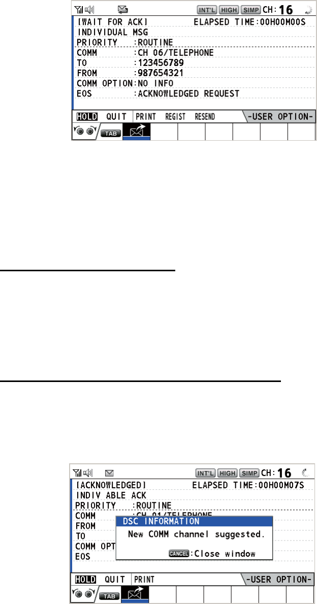
4. DSC GENERAL MESSAGE CALLING, RECEIVING
4-3
The timer starts counting up the time since the call was sent. After the call is sent,
the equipment waits for acknowledgement of the call, showing the WAIT FOR
ACK screen as below.
When the ACK is received, the audio alarm sounds and the pop-up message
"ROUTINE (or SAFETY, URGENCY) INDIVIDUAL ACK received! [CANCEL]:
Stop alarm" appears on the screen as below. The timer starts counting up the time
since the ACK was received.
There are three types of ACK messages; [ABLE ACK], [UNABLE ACK] or [ABLE
CHANGE CHANNEL ACK].
11. Do one of the following depending on the message type shown at step 10.
Able acknowledge call received
1) Press the CANCEL key to silence the audio alarm and erase the pop-up mes-
sage.
2) Communicate by radiotelephone.
3) After you have completed communications, rotate the CHANNEL/ENTER
knob to select [QUIT] in the user options area then push the knob.
Able to change channel acknowledge call received
This call means that the station you sent the individual call to accepts your call with
the channel specified.
1) Press the CANCEL key to silence the audio alarm and erase the pop-up mes-
sage. The following message appears on the screen.
2) Press the CANCEL key to erase the message. The working channel is
changed to one that the station specified. You can now communicate by ra-
diotelephone.
3) After you have completed communications, rotate the CHANNEL/ENTER
knob to select [QUIT] in the user options area then push the knob.
REGIST
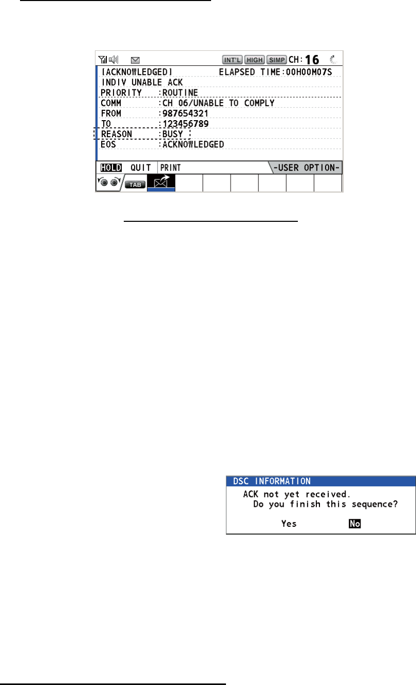
4. DSC GENERAL MESSAGE CALLING, RECEIVING
4-4
Unable acknowledge call received
1) Press the CANCEL key to silence the audio alarm and erase the pop-up mes-
sage. The reason for [UNABLE ACK] is displayed on the screen.
Reason for unable to acknowledge
2) Rotate the CHANNEL/ENTER knob to select [QUIT] in the user options area
then push the knob.
Note: If the coast station sends the message "QUEUE INDICATION", wait un-
til your turn comes.
If there is no response from the station, do one of the following procedures:
• Resend call: Rotate the CHANNEL/ENTER knob to select [RESEND] in the user
options area then push the knob.
• Cancel call: Rotate the CHANNEL/EN-
TER knob to select [QUIT] in the user op-
tions area then push the knob. The
message as shown in the right figure ap-
pears.
Rotate the CHANNEL/ENTER knob to
select [Yes] then push the knob.
4.1.2 How to receive an individual call
Unable acknowledge is sent automatically or manually depending on the acknowl-
edgement method setting (see section 5.16). Able acknowledge is sent only manually.
Note: All sessions must be quit or put on hold to enable automatic acknowledge.
Send unable acknowledge automatically
If the channel specified by the sending station is one that you cannot use, an unable
acknowledge [CAN’T USE CH] is sent automatically. The [ACK SETTINGS] menu is
set to [AUTO (UNABLE)]. It takes a few seconds to transmit the call.
• NO REASON
• BUSY
• EQUIP ERROR
• CAN’T USE CH
• CAN’T USE MODE
• QUEUE INDICATION
• STATION BARRED
• OPERATOR ABSENT
• TEMP. UNAVAILABLE
: No reason given
: Busy
: Equipment disabled
: Unable to use proposed channel
: Unable to use proposed mode
: Queue indication
: Station barred
: No operator available
: Operator temporarily unavailable
REGIST
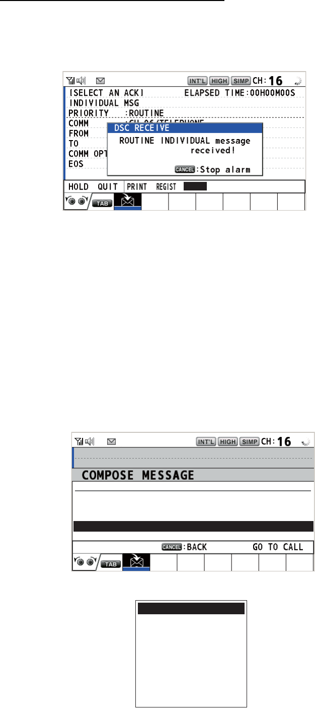
4. DSC GENERAL MESSAGE CALLING, RECEIVING
4-5
Send able/unable acknowledge manually
When an individual call is received with the setting [MANUAL] on the [ACK SET-
TINGS] menu, the audio alarm sounds and the pop-up message "ROUTINE (SAFE-
TY, URGENCY) INDIVIDUAL message received! [CANCEL]: Stop alarm" appears on
the screen as below.
Press the CANCEL key to silence the audio alarm and erase the pop-up message.
There are three types of ACK transmission; able acknowledge, able to change chan-
nel and unable acknowledge. Follow the appropriate procedure below.
• How to send able acknowledge call
1. With [ACCEPT] selected, push the CHANNEL/ENTER knob to send the able
acknowledge call.
2. Communicate by radiotelephone.
3. After you have completed communications, rotate the CHANNEL/ENTER knob
to select [QUIT] in the user options area then push the knob.
• How to send unable acknowledge call
1. Rotate the CHANNEL/ENTER knob to select [UNABLE] in the user options
area then push the knob.
2. With [REASON] selected, push the CHANNEL/ENTER knob.
UNABLE
ACCEPT PROPOSE
[
SELECT
AN
ACK
]
INDIVIDUAL
MSG
ELAPSED
T
I
ME :
00
H
01
M
15
S
MSG TYPE : INDIVIDUAL ACK
TO
:
123456789
PRIORITY
: ROUTINE
COMM MODE
: UNABLE TO COMPLY
REASON
: NO REASON
COMM CH
: 06
NO REASON
BUSY
EQUIP ERROR
CAN’T USE CH
CAN’T USE MODE
QUEUE INDICATION
STATION BARRED
OPERATOR ABSENT
TEMP. UNAVAILABLE
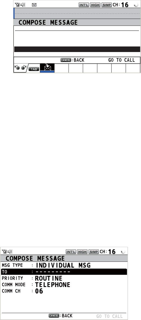
4. DSC GENERAL MESSAGE CALLING, RECEIVING
4-6
3. Rotate the CHANNEL/ENTER knob to select the reason for unable then push
the knob.
4. With [GO TO CALL] selected, push the CHANNEL/ENTER knob to send un-
able acknowledge call.
• How to send able acknowledge call and change channel
1. Rotate the CHANNEL/ENTER knob to select [PROPOSE] in the user options
area then push the knob.
2. With [COMM CH] selected, push the CHANNEL/ENTER knob.
3. Rotate the CHANNEL/ENTER knob to select [SELECT] or [MANUAL] then
push the knob.
[SELECT]: The options window appears. Rotate the CHANNEL/ENTER knob
to select a channel then push the knob.
[MANUAL]: Enter a channel then push the CHANNEL/ENTER knob.
4. With [GO TO CALL] selected, push the CHANNEL/ENTER knob to send the
able to change channel acknowledge call.
5. Communicate by radiotelephone.
6. After you have completed communications, rotate the CHANNEL/ENTER knob
to select [QUIT] in the user options area then push the knob.
4.2 Group Call
A group call is for calling a specific group by specifying its group MMSI. When you set
the group call in the address book, the group MMSI is automatically stored as your
ship’s group MMSI.
4.2.1 How to send a group call
1. Press the OTHER DSC MSG key.
[
SELECT
AN
ACK
]
INDIVIDUAL
MSG
ELAPSED
T
I
ME :
00
H
01
M
15
S
MSG TYPE : INDIVIDUAL ACK
TO
:
123456789
PRIORITY
: ROUTINE
COMM MODE
: TELEPHONE
COMM CH : 01
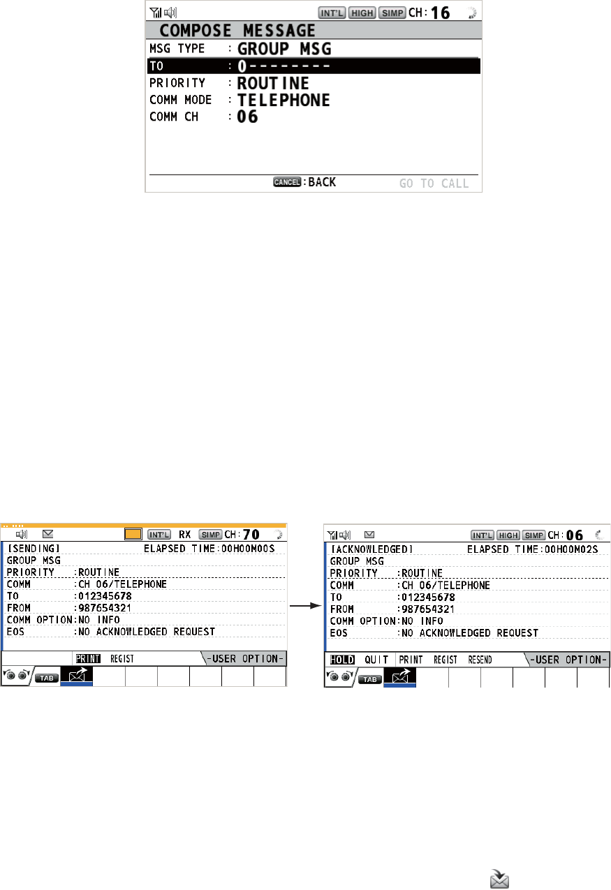
4. DSC GENERAL MESSAGE CALLING, RECEIVING
4-7
2. Rotate the CHANNEL/ENTER knob to select [MSG TYPE] then push the knob.
3. Rotate the CHANNEL/ENTER knob to select [GROUP MSG] then push the knob.
4. With [TO] selected, push the CHANNEL/ENTER knob.
5. Rotate the CHANNEL/ENTER knob to select [DIRECT INPUT] or [ADDRESS
BOOK DATA] then push the knob.
[DIRECT INPUT]: Enter group MMSI (eight digits) with the numeric keys then
push the CHANNEL/ENTER knob.
[ADDRESS BOOK DATA]: Select an MMSI from the [ADDRESS BOOK] (see
section 5.13) then push the CHANNEL/ENTER knob.
6. With [COMM CH] selected, push the CHANNEL/ENTER knob.
7. Rotate the CHANNEL/ENTER knob to select [SELECT] or [MANUAL] then push
the knob.
[SELECT]: The options window appears. Rotate the CHANNEL/ENTER knob to
select the channel then push the knob.
[MANUAL]: Enter the channel then push the CHANNEL/ENTER knob.
8. With [GO TO CALL] selected, push the CHANNEL/ENTER knob to send the
group call. The screen changes as below.
9. Communicate by radiotelephone.
10. After you have completed communications, rotate the CHANNEL/ENTER knob to
select [QUIT] in the user options area then push the knob.
4.2.2 How to receive a group call
Group MMSI must be registered in order to receive a group call (see
paragraph 5.13.2).
When a group call is received, the audio alarm sounds. The icon ( ) appears in the
tab area, and the pop-up message "GROUP message received! [CANCEL]: Stop
alarm" appears.
TX
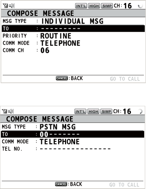
4. DSC GENERAL MESSAGE CALLING, RECEIVING
4-8
1. Press the CANCEL key to silence the audio alarm and erase the pop-up mes-
sage. The channel is automatically tuned to the received channel.
2. Watch on the working channel. Communicate by radiotelephone.
3. After you have completed communications, rotate the CHANNEL/ENTER knob to
select [QUIT] in the user options area then push the knob.
4.3 PSTN Call
The PSTN call allows the making and receiving of telephone calls over public switched
telephone networks. To use the PSTN call feature, use a handset which has a HOOK
ON/OFF function. The standard supply handset has this feature.
4.3.1 How to send a PSTN call
1. Press the OTHER DSC MSG key.
2. Rotate the CHANNEL/ENTER knob to select [MSG TYPE] then push the knob.
3. Rotate the CHANNEL/ENTER knob to select [PSTN MSG] then push the knob.
4. With [TO] selected, push the CHANNEL/ENTER knob.
5. Rotate the CHANNEL/ENTER knob to select [DIRECT INPUT], [ADDRESS
BOOK DATA] or [AIS TARGET DATA] then push the knob.
[DIRECT INPUT]: Enter the MMSI of coast station (seven digits) with the numeric
keys then push the CHANNEL/ENTER knob.
[ADDRESS BOOK DATA]: Select an MMSI from the [ADDRESS BOOK] (see
section 5.13) then push the CHANNEL/ENTER knob.
[AIS TARGET DATA]: Select an MMSI from the [AIS TARGET LIST] then push
the CHANNEL/ENTER knob.
6. With [TEL NO.] selected, push the CHANNEL/ENTER knob.
7. Enter telephone no. (up to 16 digits) with the numeric keys then push the CHAN-
NEL/ENTER knob.
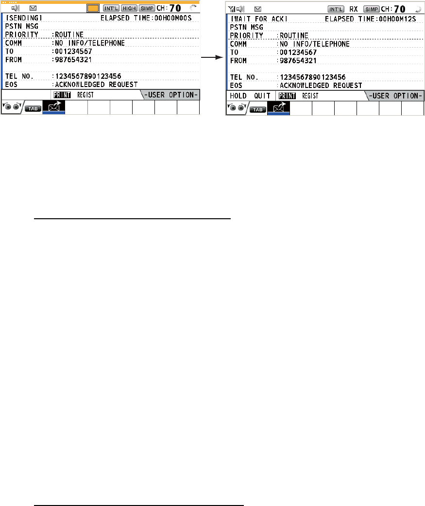
4. DSC GENERAL MESSAGE CALLING, RECEIVING
4-9
8. With [GO TO CALL] selected, push the CHANNEL/ENTER knob to send the
PSTN call. After the call has been sent, the WAIT FOR ACK screen appears. The
elapsed time since sending the call and the countdown for resending are dis-
played.
When you receive an acknowledge message, a pop-up message appears.
Note: The time period of countdown for resending is five seconds. After five sec-
onds have passed, the call is resent. After five seconds have passed since re-
sending the call, the pop-up message for time out or no response appears.
9. Do one of the following depending on ACK message.
Able acknowledge message received
If the PSTN call is accepted, the PSTN connection call is sent. When you receive the
PSTN ACK message, the pop-up message "PSTN connected. Pick up HANDSET" ap-
pears and the audio alarm sounds. The communication channel changes.
Note: If you have already picked up the handset before the pop-up message appears,
a pop-up message which suggests you to push the CHANNEL/ENTER knob appears.
Push the CHANNEL/ENTER knob to accept.
1. Pick up the handset and communicate with the party you called. The elapsed time
since starting communication is displayed.
2. To quit the communications, do one of the following.
• On hook the handset. END OF CALL is sent automatically. The waiting ACK for
END OF CALL screen appears. When you receive the ACK, rotate the CHAN-
NEL/ENTER knob to select [QUIT] then push the knob.
Note: Be sure to on hook the handset to quit the communication so as not to
incur further charges.
• When the PSTN line is disconnected by the coast station, you receive the END
OF CALL ACK message. Rotate the CHANNEL/ENTER knob to select [QUIT]
then push the knob.
Unable acknowledge message received
When you receive an unable acknowledge message, the audio alarm sounds and a
pop-up message appears. Rotate the CHANNEL/ENTER knob to select [QUIT] then
push the knob.
TX
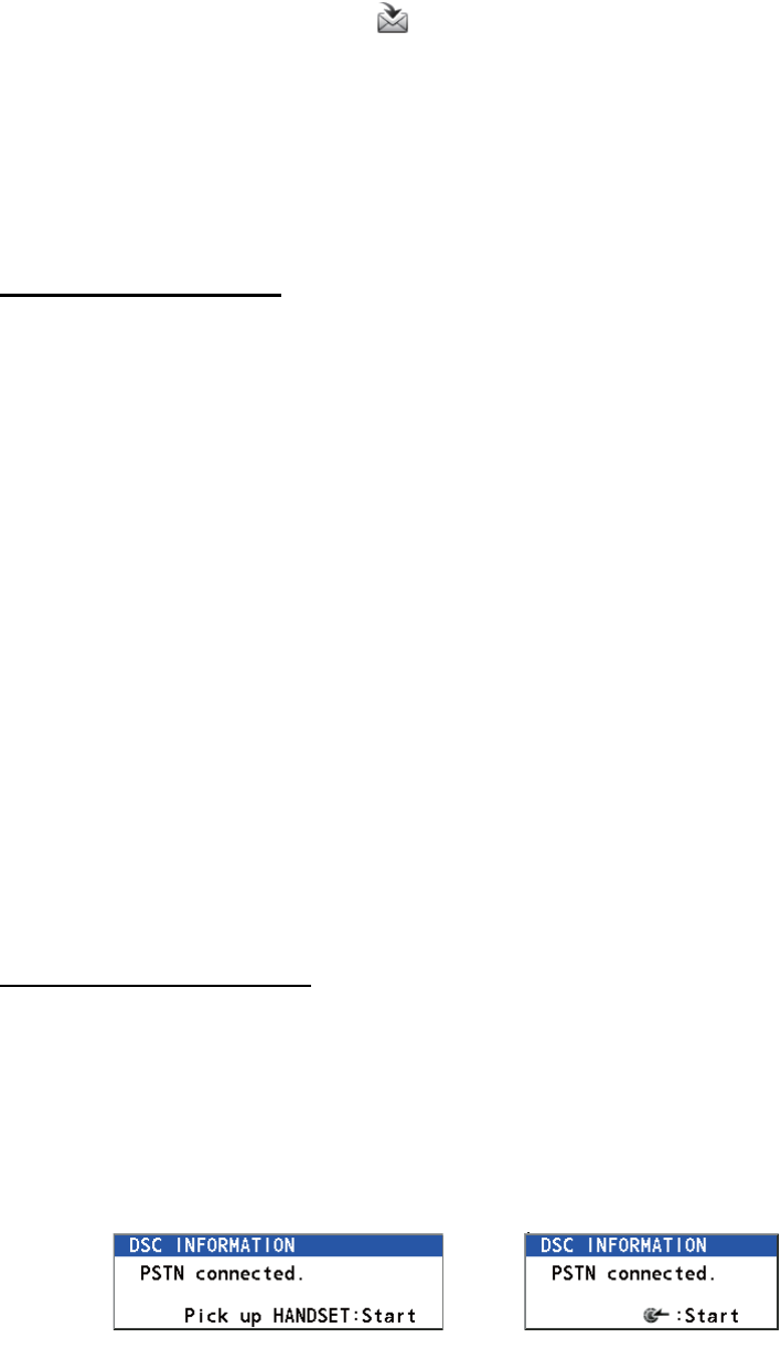
4. DSC GENERAL MESSAGE CALLING, RECEIVING
4-10
4.3.2 How to receive a PSTN call
When a PSTN call is received, the icon appears in the tab area. An able/unable
acknowledge is sent automatically according to the setting of [PSTN] on the [ACK
SETTINGS].
• [AUTO (ABLE)]: The automatic able acknowledge (which means you can commu-
nicate with party) is sent.
• [AUTO (UNABLE)]: The automatic unable acknowledge (which means you cannot
communicate with party) is sent.
Able acknowledgement
The automatic able acknowledge is sent and the pop-up message "PSTN connected
pick up HANDSET!" appears.
Note: If you have already picked up the handset before the pop-up message appears,
a pop-up message which suggests you to push the CHANNEL/ENTER knob appears.
Push the CHANNEL/ENTER knob to accept.
1. Pick up the handset. When you receive the PSTN ACK message, the screen for
telephone calling appears. Communicate with the party. The elapsed time since
starting communication is displayed.
2. To quit the communication, do one of the following.
• On hook the handset. END OF CALL is sent automatically. The waiting ACK for
END OF CALL screen appears. When you receive the ACK, rotate the CHAN-
NEL/ENTER knob to select [QUIT] then push the knob.
Note: Be sure to on hook the handset to quit the communication so as not to
incur further charges.
• When the PSTN line is disconnected by the coast station, you receive the END
OF CALL ACK message. Rotate the CHANNEL/ENTER knob to select [QUIT]
then push the knob.
After disconnection of the PSTN line, the END OF CALL ACK is sent.
Unable acknowledgement
The automatic unable acknowledge is sent. The audio alarm sounds and the LED
flashes in green. Press the CANCEL key.
4.3.3 Caution for a PSTN call
After you send a PSTN call and receive an ACK (regardless of on hook or off hook
condition), the following pop-up message appears.
If you do not push the CHANNEL/ENTER knob or pick up the handset within 60 sec-
onds, the PSTN call is disconnected because of timeout.
On hook Off hook
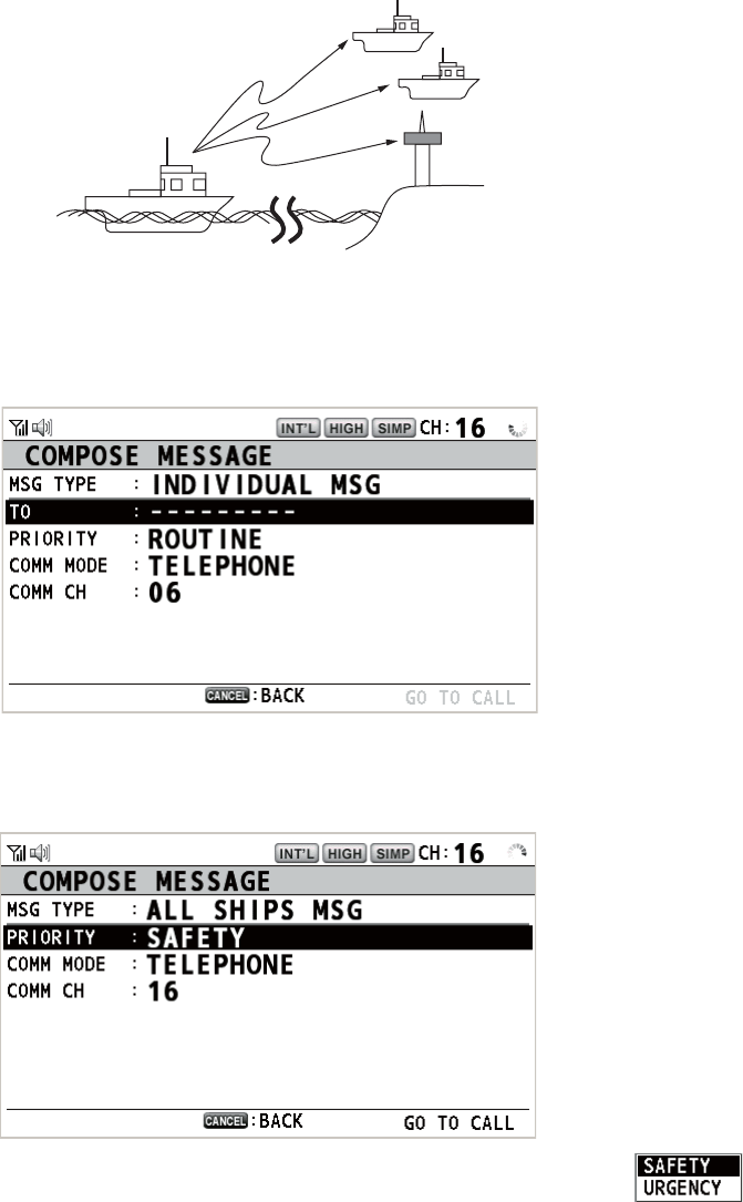
4. DSC GENERAL MESSAGE CALLING, RECEIVING
4-11
4.4 All Ships Call
When an urgent but not life-endangering situation arises on your ship, for example,
engine trouble, send an all ships call to request assistance. After sending the call, you
can communicate by radiotelephone. Do the following before beginning actual com-
munications:
URGENCY priority: Say "PAN" three times followed by your call sign.
SAFETY priority: Say "SECURITE" three times followed by your call sign.
4.4.1 How to send an all ships call
1. Press the OTHER DSC MSG key.
2. Rotate the CHANNEL/ENTER knob to select [MSG TYPE] then push the knob.
3. Rotate the CHANNEL/ENTER knob to select [ALL SHIPS MSG] then push the
knob.
4. With [PRIORITY] selected, push the CHANNEL/ENTER knob.
5. Rotate the CHANNEL/ENTER knob to select [SAFETY] or [URGENCY] then push
the knob.
6. With [COMM CH] selected, push the CHANNEL/ENTER knob.
Coast
station
Your ship
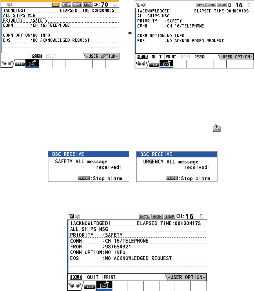
4. DSC GENERAL MESSAGE CALLING, RECEIVING
4-12
7. Rotate the CHANNEL/ENTER knob to select [SELECT] or [MANUAL] then push
the knob.
[SELECT]: The options window appears. Rotate the CHANNEL/ENTER knob to
select the channel then push the knob.
[MANUAL]: Enter the channel then push the CHANNEL/ENTER knob.
8. With [GO TO CALL] selected, push the CHANNEL/ENTER knob to send the call.
The screen changes as below.
9. Communicate by radiotelephone.
10. After you have completed communications, rotate the CHANNEL/ENTER knob to
select [QUIT] in the user options area then push the knob.
4.4.2 How to receive an all ships call
When you receive an all ships call, the audio alarm sounds. The icon ( ) appears in
the tab area, and the pop-up message "SAFETY (URGENCY) ALL message received!
[CANCEL]: Stop alarm" appears.
1. Press the CANCEL key to silence the audio alarm and erase the pop-up mes-
sage. The channel is automatically tuned to the received channel.
2. Watch on the working channel. Communicate by radiotelephone.
3. After you have completed communications, rotate the CHANNEL/ENTER knob to
select [QUIT] in the user options area then push the knob.
TX
REGIST
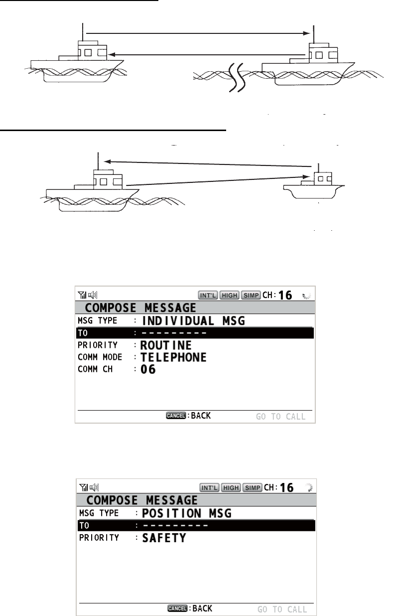
4. DSC GENERAL MESSAGE CALLING, RECEIVING
4-13
4.5 Position Call
There are two types of position calls: your ship requests the position of another ship
and other station requires your ship's position.
Find position of other station
Send your ship's position to other station
4.5.1 How to request other ship's position
1. Press the OTHER DSC MSG key.
2. Rotate the CHANNEL/ENTER knob to select [MSG TYPE] then push the knob.
3. Rotate the CHANNEL/ENTER knob to select [POSITION MSG] then push the
knob. [PRIORITY] is automatically selected to [SAFETY].
4. With [TO] selected, push the CHANNEL/ENTER knob.
(1) Position request call
(2) Position Information
Your Station Other Station
Your Station
(1) Request ship's position
(2) Send position Information
Other Station
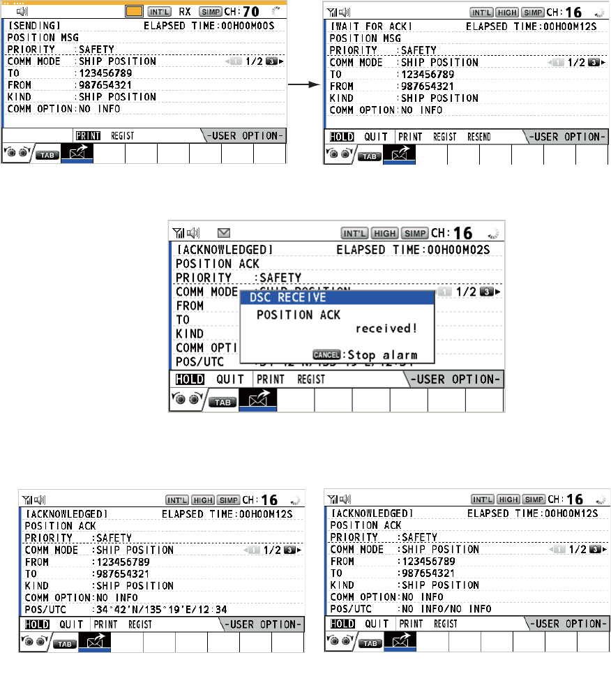
4. DSC GENERAL MESSAGE CALLING, RECEIVING
4-14
5. Rotate the CHANNEL/ENTER knob to select [DIRECT INPUT], [ADDRESS
BOOK DATA] or [AIS TARGET DATA] then push the knob.
[DIRECT INPUT]: Enter the MMSI of station, which you want to know its position,
with the numeric keys then push the CHANNEL/ENTER knob.
[ADDRESS BOOK DATA]: Select an MMSI from the [ADDRESS BOOK] (see
section 5.13) then push the CHANNEL/ENTER knob.
[AIS TARGET DATA]: Select an MMSI from the [AIS TARGET LIST] then push
the CHANNEL/ENTER knob.
6. With [GO TO CALL] selected, push the CHANNEL/ENTER knob to send the po-
sition call. After the call has been sent, the WAIT FOR ACK screen appears. The
elapsed time since sending the call is displayed.
When you receive an acknowledge message, the audio alarm sounds and the
pop-up message "POSITION ACK received! [CANCEL]: Stop alarm" appears.
7. Press the CANCEL key to silence the audio alarm and erase the pop-up mes-
sage. There are two types of ACK screens, one with position information and one
with no position information.
TX
Position information included No position information
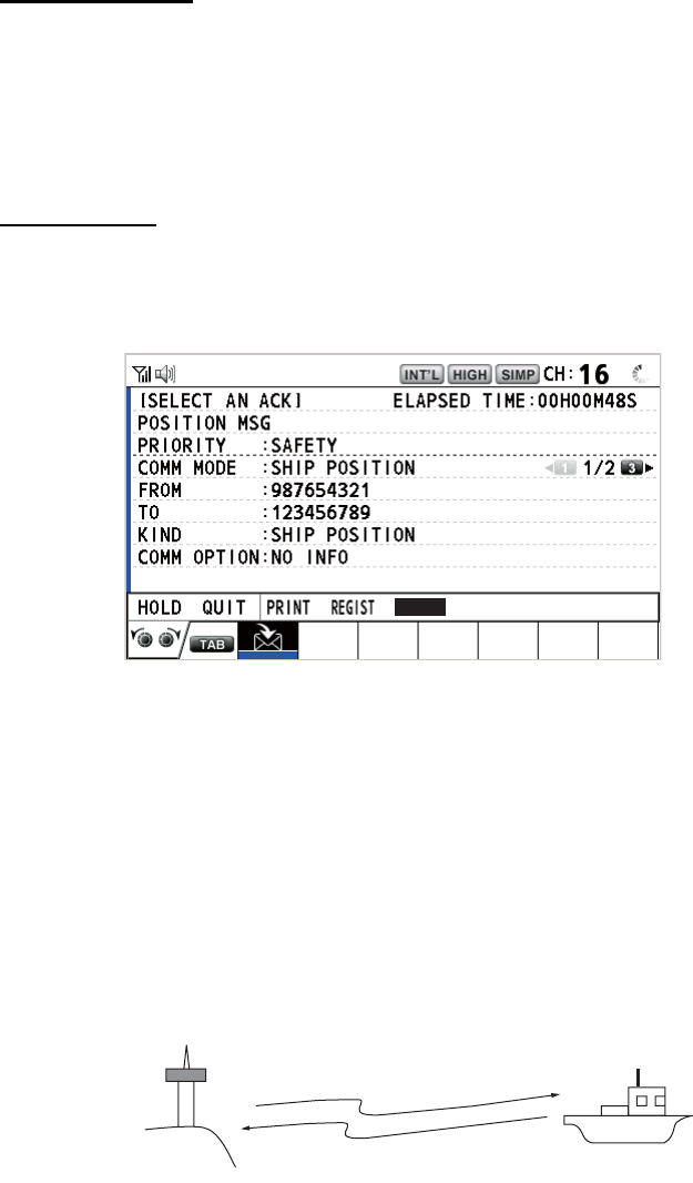
4. DSC GENERAL MESSAGE CALLING, RECEIVING
4-15
4.5.2 Other ship requests your position
You can turn automatic acknowledge of position request on with [POSITION MSG] on
the [ACK SETTINGS] menu (see section 5.16).
Automatic reply
When another ship requests your position and the setting of [POSITION MSG] on the
[ACK SETTINGS] menu is [AUTO], the equipment automatically transmits a reply.
There are two types of automatic replies, one with position information (the setting is
[AUTO (ABLE)]) and the other with no position information (the setting is [AUTO (UN-
ABLE)]).
Manual reply
When a position request message is received and the setting of [POSITION MSG] on
the [ACK SETTINGS] menu is [MANUAL], send the reply manually.
To silence the audio alarm, press the CANCEL key.
• Send the ACK with position information: With [ACCEPT] selected, push the
CHANNEL/ENTER knob. The message with position information is sent.
• Send the ACK with no position information: Rotate the CHANNEL/ENTER knob
to select [UNABLE] in the user options area then push the knob. The message with
no position information is sent.
4.6 How to Receive a Polling Request
Polling means a coast station wants to confirm if it is within communicating range of
your ship.
4.6.1 Automatic reply
When a polling request message is received with [AUTO] setting on [POLLING MSG]
of the [ACK SETTINGS] menu, an acknowledge is sent automatically. See
section 5.16.
UNABLE
ACCEPT
(1) Polling
(2) Acknowledge Your Ship
Coast
station
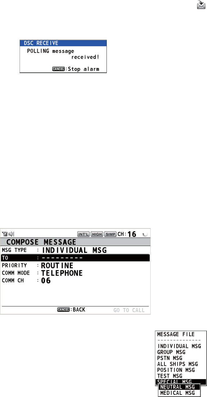
4. DSC GENERAL MESSAGE CALLING, RECEIVING
4-16
4.6.2 Manual reply
When you receive a polling request message, the audio alarm sounds. The icon ( )
appears in the tab area, and the pop-up message shown below appears. The equip-
ment is set up for manual acknowledge: [POLLING MSG] on the [ACK SETTINGS]
menu is [MANUAL].
1. Press the CANCEL key to silence the audio alarm and erase the pop-up mes-
sage.
2. Rotate the CHANNEL/ENTER knob to select [ACK] then push the knob to send
the polling acknowledge message.
3. Rotate the CHANNEL/ENTER knob to select [QUIT] then push the knob.
4.7 Neutral Craft Call
The neutral craft call, which contains your MMSI, informs all ships that your ship is not
a participant in an armed conflict. The neutral craft call must be enabled on the [SPE-
CIAL MSG] menu. See section 5.17.
4.7.1 How to send a neutral craft call
1. Press the OTHER DSC MSG key.
2. Rotate the CHANNEL/ENTER knob to select [MSG TYPE] then push the knob.
3. Rotate the CHANNEL/ENTER knob to select [SPECIAL
MSG] then push the knob.
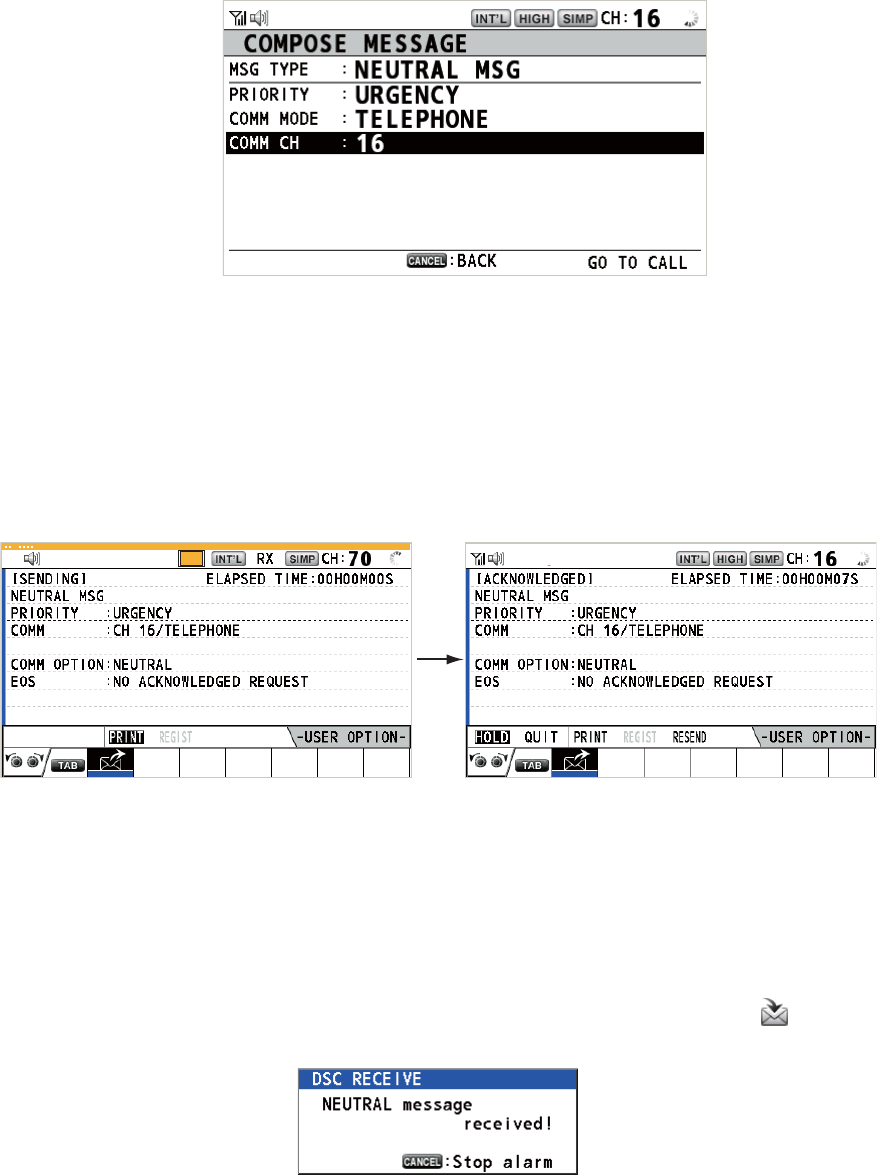
4. DSC GENERAL MESSAGE CALLING, RECEIVING
4-17
4. Rotate the CHANNEL/ENTER knob to select [NEUTRAL MSG] then push the
knob. [PRIORITY] is automatically selected to [URGENCY].
5. With [COMM CH] selected, push the CHANNEL/ENTER knob.
6. Rotate the CHANNEL/ENTER knob to select [SELECT] or [MANUAL] then push
the knob.
[SELECT]: The options window appears. Rotate the CHANNEL/ENTER knob to
select the channel then push the knob.
[MANUAL]: Enter the channel then push the CHANNEL/ENTER knob.
7. With [GO TO CALL] selected, push the CHANNEL/ENTER knob to send the neu-
tral craft call.
8. Inform all ships by radiotelephone that your ship is not a participant in armed con-
flict.
9. After you have completed communications, rotate the CHANNEL/ENTER knob to
select [QUIT] in the user options area then push the knob.
4.7.2 How to receive a neutral craft call
When you receive a neutral craft call, the audio alarm sounds. The icon ( ) appears
in the tab area, and the following pop-up message appears.
TX
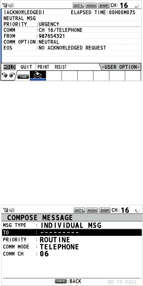
4. DSC GENERAL MESSAGE CALLING, RECEIVING
4-18
1. Press the CANCEL key to silence the audio alarm and erase the pop-up mes-
sage.
2. Watch on the working channel. Communicate by radiotelephone.
3. After you have completed communications, rotate the CHANNEL/ENTER knob to
select [QUIT] in the user options area then push the knob.
4.8 Medical Transport Call
The medical transport call informs all ships, by urgency priority, that your ship carries
medical supplies. The medical transport call must be enabled on the [SPECIAL MSG]
menu. See section 5.17.
4.8.1 How to send a medical transport call
1. Press the OTHER DSC MSG key.
2. Rotate the CHANNEL/ENTER knob to select [MSG TYPE] then push the knob.
3. Rotate the CHANNEL/ENTER knob to select [SPECIAL MSG] then push the
knob.
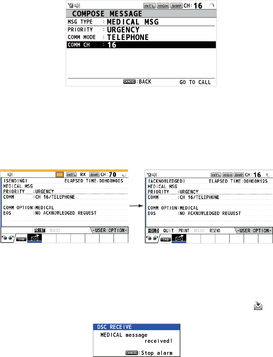
4. DSC GENERAL MESSAGE CALLING, RECEIVING
4-19
4. Rotate the CHANNEL/ENTER knob to select [MEDICAL MSG] then push the
knob. [PRIORITY] is automatically selected to [URGENCY].
5. With [COMM CH] selected, push the CHANNEL/ENTER knob.
6. Rotate the CHANNEL/ENTER knob to select [SELECT] or [MANUAL] then push
the knob.
[SELECT]: The options window appears. Rotate the CHANNEL/ENTER knob to
select the channel then push the knob.
[MANUAL]: Enter the channel then push the CHANNEL/ENTER knob.
7. With [GO TO CALL] selected, push the CHANNEL/ENTER knob to send the med-
ical transport call.
8. Inform all ships by radiotelephone that your ship is transporting medical supplies.
9. After you have completed communications, rotate the CHANNEL/ENTER knob to
select [QUIT] in the user options area then push the knob.
4.8.2 How to receive a medical transport call
When you receive a medical transport call, the audio alarm sounds. The icon ( ) ap-
pears in the tab area, and the following pop-up message appears.
TX
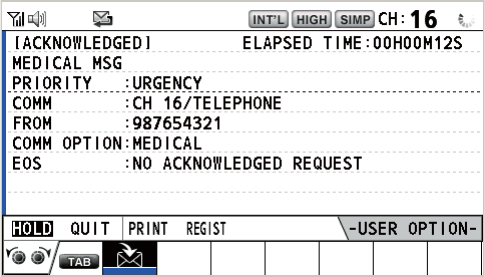
4. DSC GENERAL MESSAGE CALLING, RECEIVING
4-20
1. Press the CANCEL key to silence the audio alarm and erase the pop-up mes-
sage.
2. Watch on the working channel. Communicate by radiotelephone.
3. After you have completed communications, rotate the CHANNEL/ENTER knob to
select [QUIT] in the user options area then push the knob.
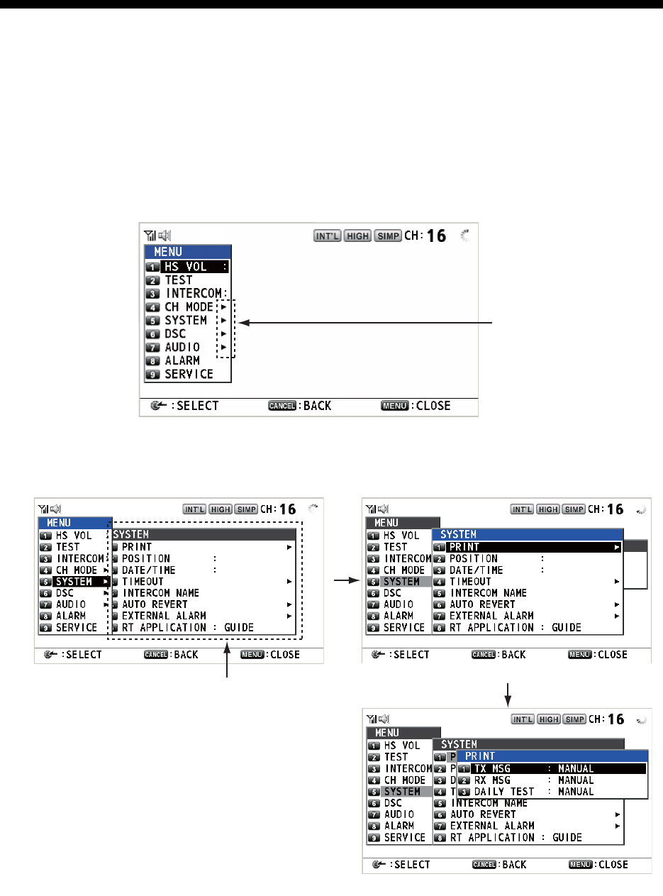
5-1
5. MENU OPERATION
The menu can be accessed from both the RT and DSC screens.
Note: The menu can not be opened when awaiting acknowledgement of a distress
alert.
5.1 How to Open/Close the MENU Screen
1. Press the MENU key to open the [MENU] screen.
2. Rotate the CHANNEL/ENTER knob to select a desired menu item then push the
knob. You can also select the desired menu item by pressing the 1 to 9 keys. The
menu items that have a X indicate additional menus.
3. To close the menu screen, press the MENU key.
Note: The RT/REGION key cancels menu operation and returns control to the RT
screen.
These marks indicate
additional menus.
Menu items in next layer
Second layer
Third layer
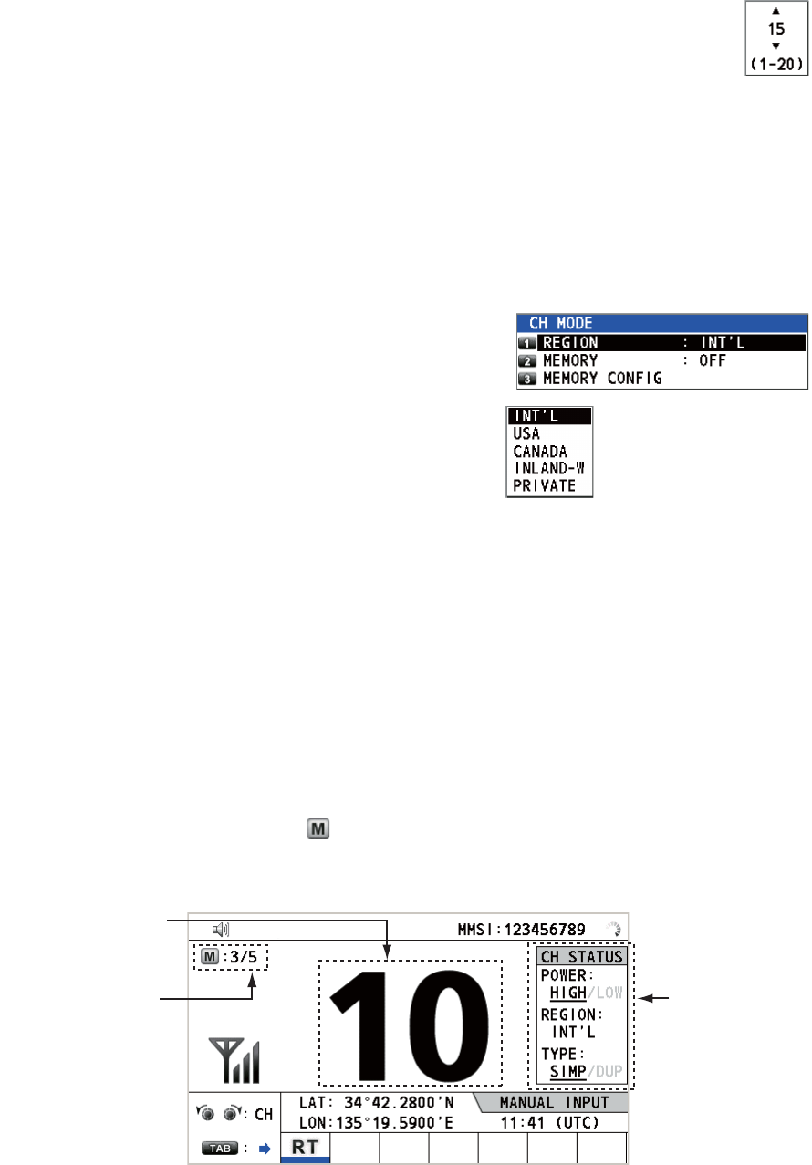
5. MENU OPERATION
5-2
5.2 Handset Volume Setting
You can adjust the volume of the loudspeaker for the handset.
1. Rotate the CHANNEL/ENTER knob to select [HS VOL] on the [MENU]
screen then push the knob.
2. Rotate the CHANNEL/ENTER knob to set the volume level then push
the knob.
5.3 Channel Setting
5.3.1 Channel region
You can change the channel region (see section 1.5).
1. Rotate the CHANNEL/ENTER knob to select
[CH MODE] on the [MENU] screen then push
the knob.
2. With [REGION] selected, push the
CHANNEL/ENTER knob.
3. Rotate the CHANNEL/ENTER knob to select the channel region then push the
knob.
5.3.2 Memory
You can easily call up the channel which you registered in the [MEMORY CONFIG]
menu (see section 5.4).
1. Rotate the CHANNEL/ENTER knob to select [CH MODE] on the [MENU] screen
then push the knob.
2. Rotate the CHANNEL/ENTER knob to select [MEMORY] then push the knob.
3. Rotate the CHANNEL/ENTER knob to select [ON] or [OFF] then push the knob.
When you select [ON], appears on the screen. On the RT screen, you can se-
lect the memory channel by rotating the CHANNEL/ENTER knob. The following
figure shows the example for CH 10.
Only permitted channel
modes are displayed,
which are set by the
installer of the equipment.
Channel number
“5” means that you
turned 5 channels of
the selected channel
region to [ON] in the
[MEMORY CONFIG]
menu.
Channel status
for CH 10
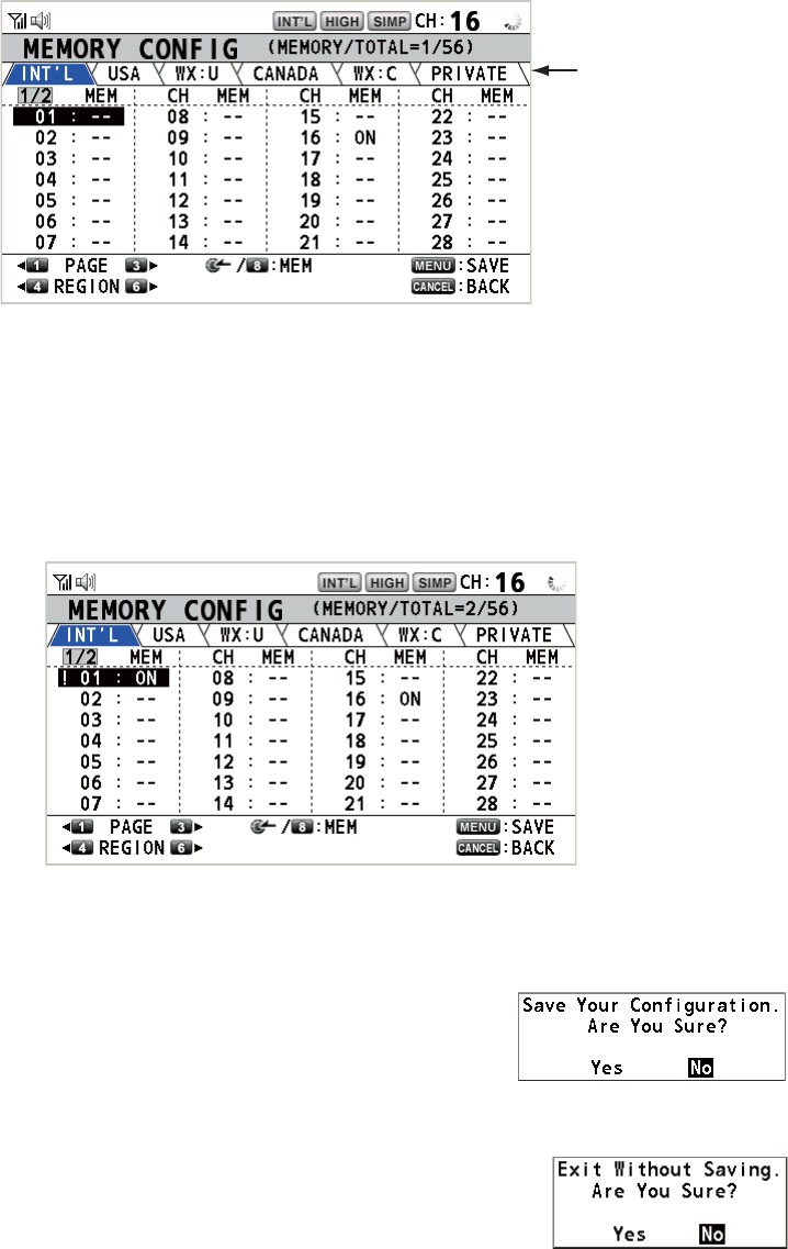
5. MENU OPERATION
5-3
5.4 Memory Configuration
You can turn on or off memory channels on the [MEMORY CONFIG] screen. You can
not turn off CH 16.
1. Rotate the CHANNEL/ENTER knob to select [CH MODE] on the [MENU] screen
then push the knob.
2. Rotate the CHANNEL/ENTER knob to select [MEMORY CONFIG] then push the
knob. The list for memory config appears.
3. Press the 4 or 6 key to switch the channel region.
4. When there are multiple pages, press the 1 key for the previous page and the 3
key for the next page.
5. Rotate the CHANNEL/ENTER knob to select the channel number then push the
knob or the 8 key. Below is the example screen for the channel number 01 select-
ed. The exclamation mark (!) and [ON] are displayed at each side of the selected
channel number.
To erase a channel, select a channel to erase then push the CHANNEL/ENTER
knob or the 8 key. The exclamation mark (!) and [ON] at each side of the selected
channel number disappear.
6. Press the MENU key to save the setting.
7. Rotate the CHANNEL/ENTER knob to select [Yes]
then push the knob.
To cancel the setting, press the CANCEL key instead of
the MENU key at step 6. The message as shown in the
right figure appears.
8. Rotate the CHANNEL/ENTER knob to select [Yes] then
push the knob.
Channel region
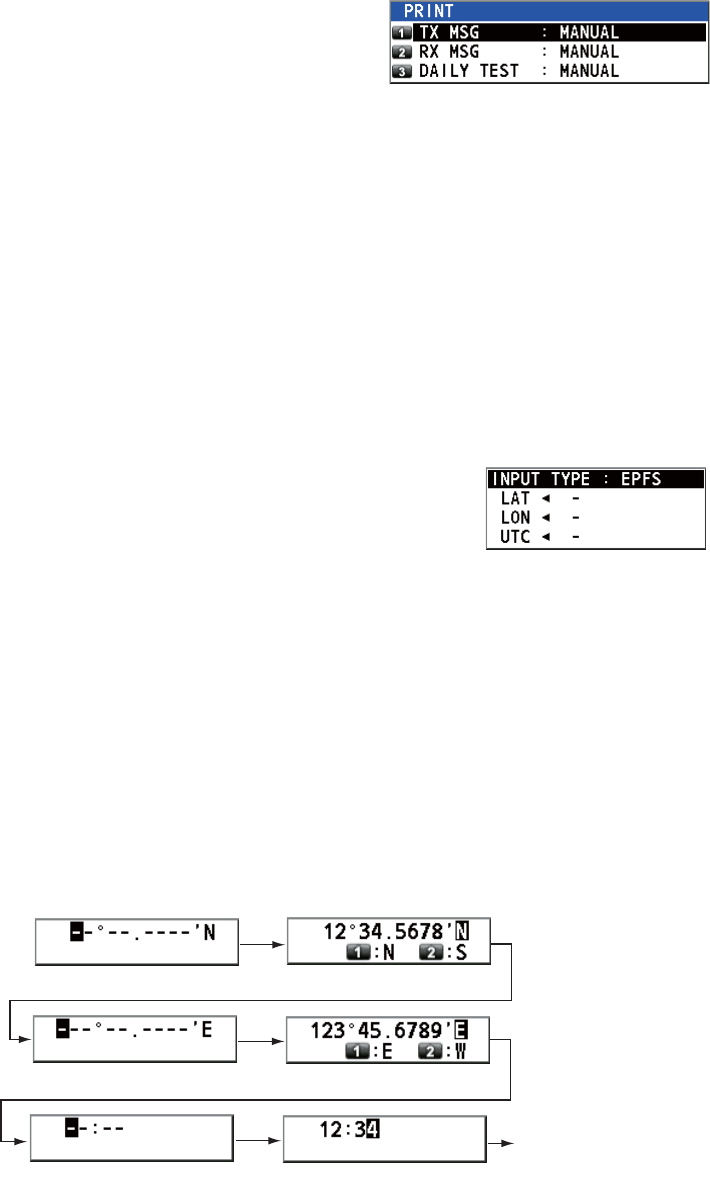
5. MENU OPERATION
5-4
5.5 How to Print Messages
The [PRINT] menu enables/disables automatic printing of all transmitted and received
calls and the results of the daily test.
1. Rotate the CHANNEL/ENTER knob to select [SYSTEM] on the [MENU] screen
then push the knob.
2. Rotate the CHANNEL/ENTER knob to select
[PRINT] then push the knob.
3. With [TX MSG] selected, push the CHANNEL/ENTER knob.
4. Rotate the CHANNEL/ENTER knob to select [AUTO] or [MANUAL] then push the
knob.
5. Set [RX MSG] and [DAILY TEST] similarly.
5.6 Position Setting
Do the following to set your position:
1. Rotate the CHANNEL/ENTER knob to select [SYSTEM] on the [MENU] screen
then push the knob.
2. Rotate the CHANNEL/ENTER knob to select [POSI-
TION] then push the knob.
3. With [INPUT TYPE] selected, push the CHANNEL/ENTER knob.
4. Rotate the CHANNEL/ENTER knob to select [EPFS], [MANUAL] or [NO INFO]
then push the knob.
[EPFS]: The position data from EPFS
[MANUAL]: Set the position data manually
[NO INFO]: No position data
For [MANUAL], go to the next step.
5. For manual input, use the numeric keys to enter current latitude/longitude posi-
tion, and UTC. To change coordinate, select it and press the 1 key for North or
East; the 2 key for South or West. Push the CHANNEL/ENTER knob after enter-
ing a line of data.
Latitude setting window
Longitude setting window
Push the
CHANNEL/
ENTER knob.
UTC setting window
Push the
CHANNEL/
ENTER knob.
Push the
CHANNEL/
ENTER knob.
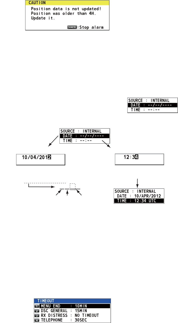
5. MENU OPERATION
5-5
Note: When the setting of [INPUT TYPE] is [MANUAL], the following message ap-
pears to ask you to update position, when position data is more than four hours old.
5.7 Date and Time Setting
Set the date and time for the system.
1. Rotate the CHANNEL/ENTER knob to select [SYSTEM] on the [MENU] screen
then push the knob.
2. Rotate the CHANNEL/ENTER knob to select [DATE/TIME] then push the knob.
• The date or time cannot be adjusted when they are in-
put from an EPFS navigator.
• If date or time is not input from an EPFS navigator, en-
ter the date and time with the numeric keys.
Note: When manually entering date and time, use UTC (Universal Time Coor-
dinated). Do not use local time.
5.8 Timeout Setting
The menu screen and/or the inactive sessions (icons) can be closed automatically
when there is no menu operation within the time specified. You can set the time inter-
val for auto closing of the menu and inactive session.
1. Rotate the CHANNEL/ENTER knob to select [SYSTEM] on the [MENU] screen
then push the knob.
2. Rotate the CHANNEL/ENTER knob to select [TIMEOUT] then push the knob.
3. Rotate the CHANNEL/ENTER knob to select the item desired then push the knob.
Select [DATE] or [TIME] then
push the CHANNEL/ENTER
knob.
Setting window for [DATE]
Enter time then push the
CHANNEL/ENTER knob.
Setting window for [TIME]
Enter date then push the CHANNEL/ENTER
knob. For example, 10/APR/2012 is entered
as 100412 (20 of 2012 is fixed).
10042012
Day Month Year
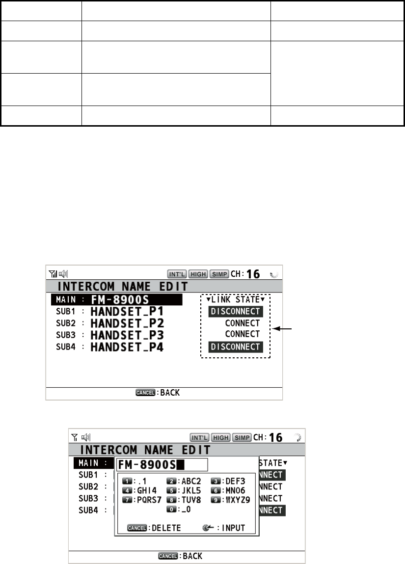
5. MENU OPERATION
5-6
4. Rotate the CHANNEL/ENTER knob to select a time interval then push the knob.
[NO TIMEOUT] leaves the menu screen and/or the inactive sessions open until
you close them manually.
5.9 How to Name the Terminal for Intercom
You can change the name of the terminal for intercom.
1. Rotate the CHANNEL/ENTER knob to select [SYSTEM] on the [MENU] screen
then push the knob.
2. Rotate the CHANNEL/ENTER knob to select [INTERCOM NAME] then push the
knob.
3. Rotate the CHANNEL/ENTER knob to select the terminal then push the knob.
Item Description Option
[MENU END] Close the menu screen automatically. [10MIN], [NO TIMEOUT]
[DSC
GENERAL]
Close the inactive sessions except the
distress alert.
[15MIN], [NO TIMEOUT]
[RX
DISTRESS]
Close the inactive sessions for the re-
ceiving distress alert.
[TELEPHONE] Close the inactive sessions for RT. [10SEC], [30SEC], [10MIN]
Connection status
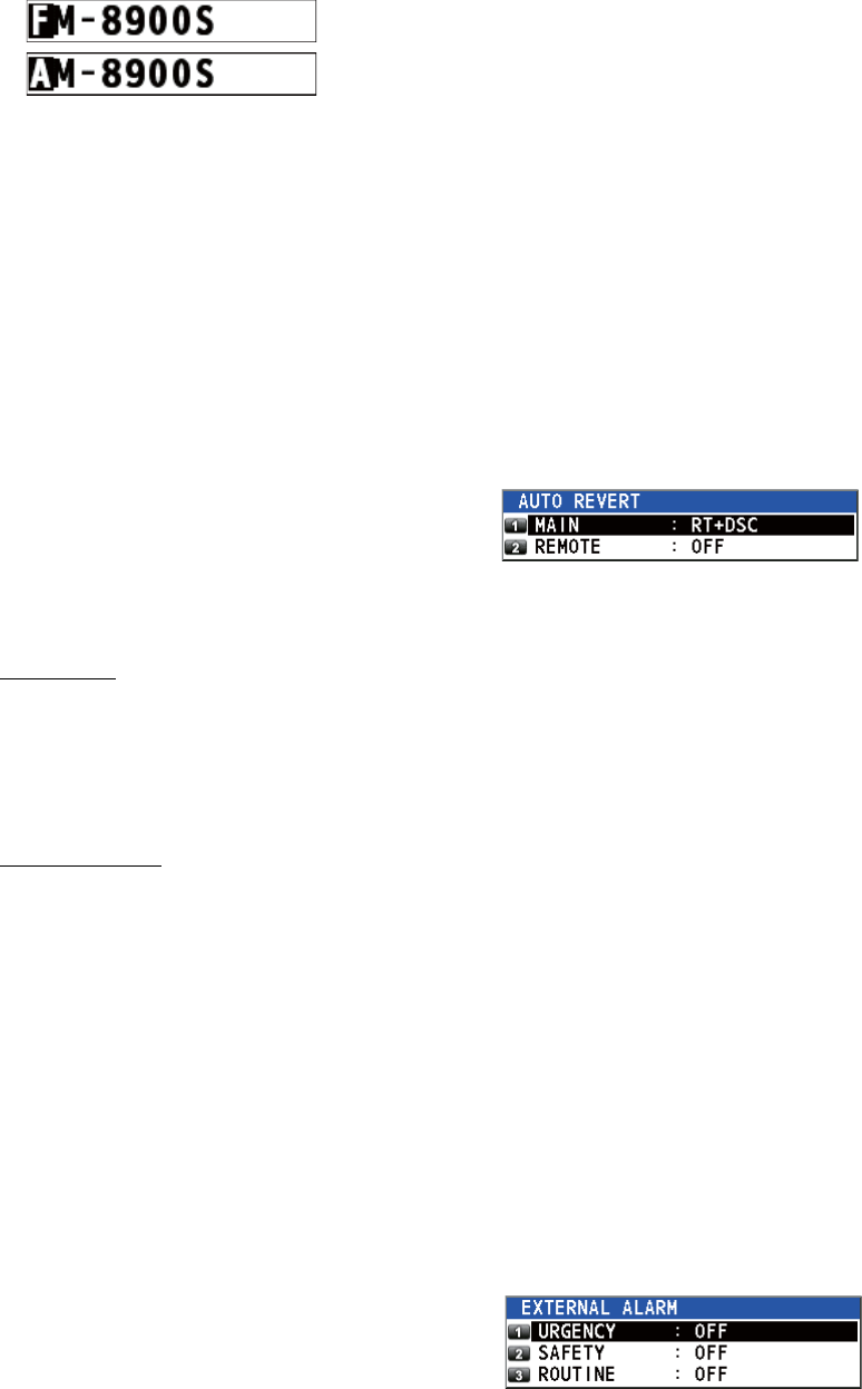
5. MENU OPERATION
5-7
4. Rotate the CHANNEL/ENTER knob to select the character to edit then press the
appropriate numeric key. To delete a character, rotate the CHANNEL/ENTER
knob to select the character to delete then press the CANCEL key.
5. Push the CHANNEL/ENTER knob.
6. Repeat steps 3 to 5 to name another terminal.
5.10 Automatic Switch to CH16
The channel can be automatically set to CH16 when the handset is on hooked.
1. Rotate the CHANNEL/ENTER knob to select [SYSTEM] on the [MENU] screen
then push the knob.
2. Rotate the CHANNEL/ENTER knob to se-
lect [AUTO REVERT] then push the knob.
3. Rotate the CHANNEL/ENTER knob to select [MAIN] (for the main unit) or [RE-
MOTE] (for the remote handset) then push the knob.
4. For [MAIN], rotate the CHANNEL/ENTER knob to select [RT+DSC], [RT] or [OFF]
then push the knob.
[RT+DSC]: Automatic switching to CH16 for all sessions
[RT]: Automatic switching to CH16 for the stand-by mode, the RT screen and the
active RT session
[OFF]: No automatic switching
For [REMOTE], rotate the CHANNEL/ENTER knob to select [ON] or [OFF] then
push the knob.
[ON]: Automatic switching to CH16 for the RT session
[OFF]: No automatic switching
Note: This function is not available during DW, scanning or PSTN.
5.11 External Alarm Setting
The [EXTERNAL ALARM] menu enables/disables output of the contact signal for ur-
gency, safety and routine messages to an external alarm system.
1. Rotate the CHANNEL/ENTER knob to select [SYSTEM] on the [MENU] screen
then push the knob.
2. Rotate the CHANNEL/ENTER knob to se-
lect [EXTERNAL ALARM] then push the
knob.
3. Rotate the CHANNEL/ENTER knob to select [URGENCY], [SAFETY] or [ROU-
TINE] then push the knob.
4. Rotate the CHANNEL/ENTER knob to select [ON] or [OFF] then push the knob.
1. Rotate the CHANNEL/ENTER knob to select “F”.
2. Press the appropriate numeric key (in this case,
the 2 key) to change “F” to “A”.
Note: Each time you press the 2 key, the character changes in the sequence of
“A” “B” “C” “2” “A” ...
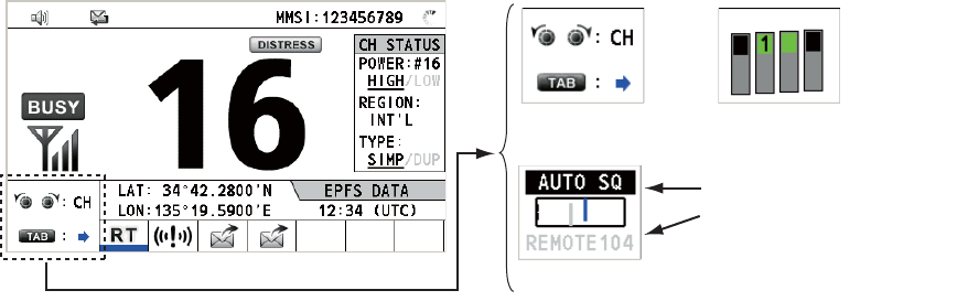
5. MENU OPERATION
5-8
• When receiving urgency, safety or routine messages, the contact signal for the cat-
egory selected to ON is output to an external alarm system.
• When receiving distress alert or distress messages, the contact signal is output to
an external alarm system regardless of the external alarm setting.
• When an alarm acknowledgement from an external alarm system is received by the
transceiver unit or an alarm pop-up message closes (with pressing the CANCEL
key, etc.), output of the contact signal to an external alarm system is stopped.
Note: An alarm pop-up message or audio alarm for the transceiver unit are not af-
fected by this condition.
5.12 RT Application Setting
You can display the guide for operations, the handset state or the squelch values at
the bottom left corner of the RT screen.
1. Rotate the CHANNEL/ENTER knob to select [SYSTEM] on the [MENU] screen
then push the knob.
2. Rotate the CHANNEL/ENTER knob to select [RT APPLICATION] then push the
knob.
3. Rotate the CHANNEL/ENTER knob to select [GUIDE], [HS STATE] or [SQ
METER] then push the knob.
[GUIDE]: The guide for operations.
[HS STATE]: The remote handset state.
[SQ METER]: The squelch values for the transceiver unit and the remote handset.
5.13 Address Book
You can register a maximum of 50 MMSIs and address names (max. 20 letters) in the
memory.
5.13.1 List for address data
1. Rotate the CHANNEL/ENTER knob to select [DSC] on the [MENU] screen then
push the knob.
[GUIDE] [HS STATE]
[SQ METER]
Upper: Transceiver unit
Lower: Remote handset
(The one which is
available is highlighted.)
2
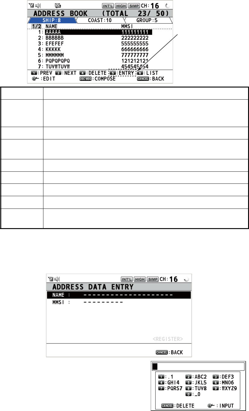
5. MENU OPERATION
5-9
2. Rotate the CHANNEL/ENTER knob to select [ADDRESS BOOK] then push the
knob.
5.13.2 How to register addresses
1. Open the [ADDRESS BOOK] screen.
2. Press the 5 key to open the [ADDRESS DATA ENTRY] screen.
3. With [NAME] selected, push the CHANNEL/
ENTER knob.
4. Enter the address name (max. 20 letters)
with the numeric keys then push the CHAN-
NEL/ENTER knob.
Key/knob Function
CHANNEL/
ENTER
• Move the cursor by rotating the CHANNEL/ENTER knob.
• Open the [ADDRESS DATA EDIT] screen by pushing the CHANNEL/
ENTER knob (see paragraph 5.13.3).
CANCEL Return to the [MENU] screen.
OTHER
DSC MSG
Open the [COMPOSE MESSAGE] screen to create a DSC message
with registered address (see paragraph 5.13.5).
1Go to the previous page.
3Go to the next page.
4Delete address (see paragraph 5.13.4).
5Open the [ADDRESS DATA ENTRY] screen (see paragraph 5.13.2).
6Switch the address type. Each press changes the type continuously
([SHIP] → [COAST] → [GROUP] → [SHIP] → ...).
When 50 addresses
have been registered,
this is grayed out.
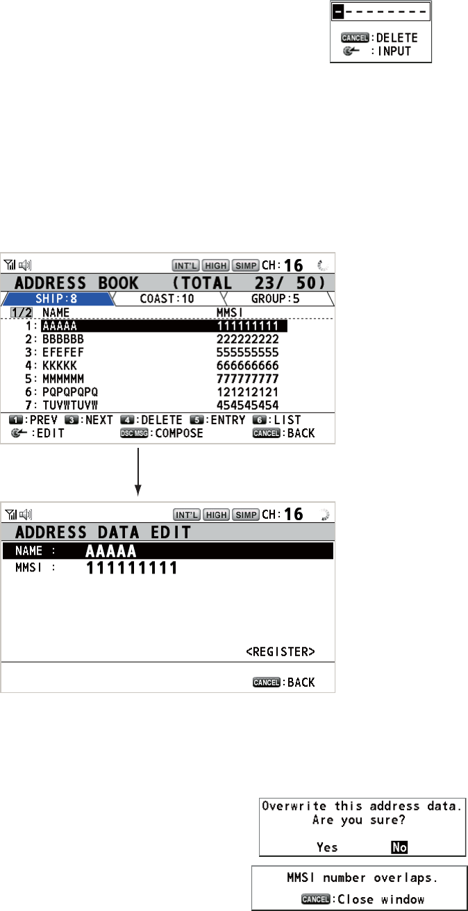
5. MENU OPERATION
5-10
5. With [MMSI] selected, push the CHANNEL/ENTER knob.
6. Enter the MMSI with the numeric keys then push the CHANNEL/ENTER knob.
7. With [REGISTER] selected, push the CHANNEL/ENTER knob.
5.13.3 How to edit addresses
1. Open the [ADDRESS BOOK] screen.
2. Rotate the CHANNEL/ENTER knob to select the address to edit then push the
knob.
3. Rotate the CHANNEL/ENTER knob to select [NAME] or [MMSI] as appropriate
then push the knob.
4. Enter the address name or MMSI with the numeric keys then push the CHANNEL/
ENTER knob.
5. Rotate the CHANNEL/ENTER knob to select
[REGISTER] then push the knob.
Note: If the MMSI is already registered to an-
other address, the error alarm sounds and a
warning pop-up message appears when se-
lecting [REGISTER].
6. Rotate the CHANNEL/ENTER knob to select [Yes] then push the knob.
Push the CHANNEL/ENTER knob.
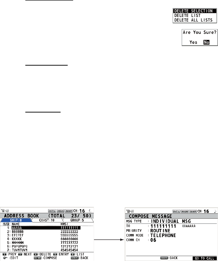
5. MENU OPERATION
5-11
5.13.4 How to delete addresses
Open the [ADDRESS BOOK] screen then follow the applicable procedure below.
Individual address
1. Rotate the CHANNEL/ENTER knob to select the address
to delete then press the 4 key.
2. Rotate the CHANNEL/ENTER knob to select [DELETE SE-
LECTION] then push the knob.
3. Rotate the CHANNEL/ENTER knob to select [Yes] then push the knob.
Address by type
1. Press the 6 key several times to select desired type.
2. Press the 4 key.
3. Rotate the CHANNEL/ENTER knob to select [DELETE LIST] then push the knob.
4. Rotate the CHANNEL/ENTER knob to select [Yes] then push the knob.
All addresses
1. Press the 4 key.
2. Rotate the CHANNEL/ENTER knob to select [DELETE ALL LISTS] then push the
knob.
3. Rotate the CHANNEL/ENTER knob to select [Yes] then push the knob.
5.13.5 How to create a DSC message with registered address
1. Open the [ADDRESS BOOK] screen.
2. Rotate the CHANNEL/ENTER knob to select the address to use.
3. Press the OTHER DSC MSG key to open the [COMPOSE MESSAGE] screen.
For the address type [SHIP] or [COAST], [MSG TYPE] is [INDIVIDUAL MSG]. For
[GROUP], [MSG TYPE] is [GROUP MSG].
Press the
OTHER DSC
MSG key.
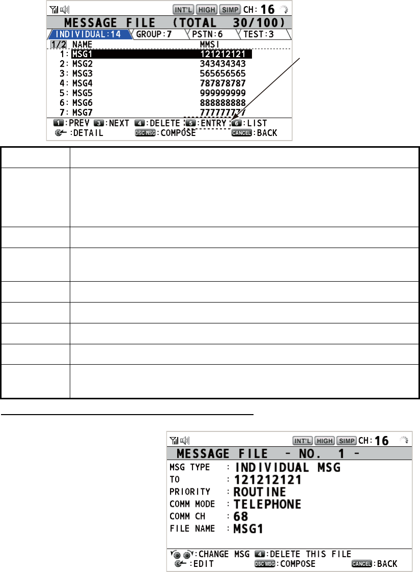
5. MENU OPERATION
5-12
5.14 TX Message Preparation
For the individual, PSTN, group and test messages, you can create messages and
store them in the memory for future use. You can edit, send or delete these messages.
A maximum of 100 messages can be stored in the memory.
5.14.1 List for message files
1. Rotate the CHANNEL/ENTER knob to select [DSC] on the [MENU] screen then
push the knob.
2. Rotate the CHANNEL/ENTER knob to select [MSG FILE] then push the knob.
Detailed information screen for message files
Rotate the CHANNEL/ENTER
knob to select the message file
desired on the [MESSAGE
FILE] list then push the knob.
The detailed information screen
for the selected message file
appears. The right figure shows
the screen for an individual
message.
Key/knob Function
CHANNEL/
ENTER
• Move the cursor by rotating the CHANNEL/ENTER knob.
• Open the detailed information screen for the selected message file by
pushing the CHANNEL/ENTER knob (see the following "Detailed in-
formation screen for message files").
CANCEL Return to the [MENU] screen.
OTHER
DSC MSG
Open the [COMPOSE MESSAGE] screen to create a DSC message with
registered message (see paragraph 5.13.5).
1Go to the previous page.
3Go to the next page.
4Delete messages (see paragraph 5.14.8).
5Open the [MESSAGE FILE ENTRY] screen.
6Switch the message type. Each press changes the type continuously
([INDIVIDUAL] → [GROUP] → [PSTN] → [TEST] → [INDIVIDUAL] → ...).
When 100 messages
have been registered,
this is grayed out.
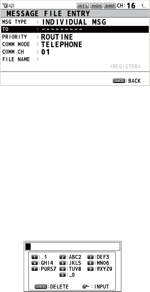
5. MENU OPERATION
5-13
Several functions can be done from this screen.
• Rotating the CHANNEL/ENTER knob: Go to the detailed information screen for the
previous or next message file.
• Pushing the CHANNEL/ENTER knob: Open the [MESSAGE FILE EDIT] screen
(see paragraph 5.14.6).
• OTHER DSC MSG key: Open the [COMPOSE MESSAGE] screen (see
paragraph 5.14.7).
• 4 key: Delete the selected message file. The confirmation message appears on the
screen. Rotate the CHANNEL/ENTER knob to select [Yes] then push the knob.
5.14.2 Individual calls
1. Open the [MESSAGE FILE] list.
2. Press the 6 key several times to select the [INDIVIDUAL] type.
3. Press the 5 key to open the [MESSAGE FILE ENTRY] screen.
4. With [TO] selected, push the CHANNEL/ENTER knob.
5. Rotate the CHANNEL/ENTER knob to select [DIRECT INPUT], [ADDRESS
BOOK DATA] or [AIS TARGET DATA] then push the knob.
[DIRECT INPUT]: Enter the MMSI of the station where to send the call then push
the CHANNEL/ENTER knob.
[ADDRESS BOOK DATA]: Select an MMSI from the [ADDRESS BOOK] (see
section 5.13) then push the CHANNEL/ENTER knob.
[AIS TARGET DATA]: Select an MMSI from the [AIS TARGET LIST] then push
the CHANNEL/ENTER knob.
6. With [COMM CH] selected, push the CHANNEL/ENTER knob.
7. Rotate the CHANNEL/ENTER knob to select [SELECT] or [MANUAL] then push
the knob.
[SELECT]: The options window appears. Rotate the CHANNEL/ENTER knob to
select the channel then push the knob.
[MANUAL]: Enter the channel then push the CHANNEL/ENTER knob.
8. With [FILE NAME] selected, push the CHANNEL/ENTER knob.
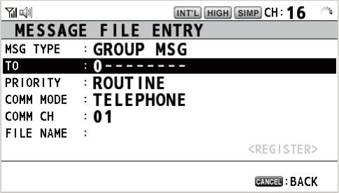
5. MENU OPERATION
5-14
9. Enter the file name (max. 20 letters) with the numeric keys then push the CHAN-
NEL/ENTER knob.
10. With [REGISTER] selected, push the CHANNEL/ENTER knob.
5.14.3 Group calls
To receive group calls, register the group MMSI in [ADDRESS BOOK].
1. Open the [MESSAGE FILE] list.
2. Press the 6 key several times to select the [GROUP] type.
3. Press the 5 key to open the [MESSAGE FILE ENTRY] screen.
4. With [TO] selected, push the CHANNEL/ENTER knob.
5. Rotate the CHANNEL/ENTER knob to select [DIRECT INPUT] or [ADDRESS
BOOK DATA] then push the knob.
[DIRECT INPUT]: Enter the group MMSI (eight digits) with the numeric keys then
push the CHANNEL/ENTER knob.
[ADDRESS BOOK DATA]: Select an MMSI from the [ADDRESS BOOK] (see
section 5.13) then push the CHANNEL/ENTER knob.
6. With [COMM CH] selected, push the CHANNEL/ENTER knob.
7. Rotate the CHANNEL/ENTER knob to select [SELECT] or [MANUAL] then push
the knob.
[SELECT]: The options window appears. Rotate the CHANNEL/ENTER knob to
select the channel then push the knob.
[MANUAL]: Enter the channel then push the CHANNEL/ENTER knob.
8. With [FILE NAME] selected, push the CHANNEL/ENTER knob.
9. Enter the file name (max. 20 letters) with the numeric keys then push the CHAN-
NEL/ENTER knob.
10. With [REGISTER] selected, push the CHANNEL/ENTER knob.
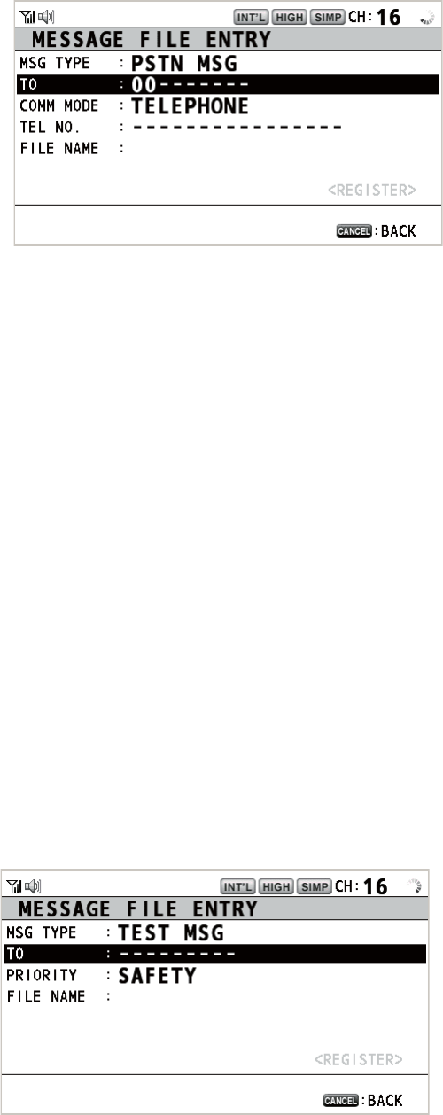
5. MENU OPERATION
5-15
5.14.4 PSTN calls
1. Open the [MESSAGE FILE] list.
2. Press the 6 key several times to select the [PSTN] type.
3. Press the 5 key to open the [MESSAGE FILE ENTRY] screen.
4. With [TO] selected, push the CHANNEL/ENTER knob.
5. Rotate the CHANNEL/ENTER knob to select [DIRECT INPUT], [ADDRESS
BOOK DATA] or [AIS TARGET DATA] then push the knob.
[DIRECT INPUT]: Enter the MMSI of coast station (seven digits) with the numeric
keys then push the CHANNEL/ENTER knob.
[ADDRESS BOOK DATA]: Select an MMSI from the [ADDRESS BOOK] (see
section 5.13) then push the CHANNEL/ENTER knob.
[AIS TARGET DATA]: Select an MMSI from the [AIS TARGET LIST] then push
the CHANNEL/ENTER knob.
6. With [TEL NO.] selected, push the CHANNEL/ENTER knob.
7. Enter the telephone no. (up to 16 digits) with the numeric keys then push the
CHANNEL/ENTER knob.
8. With [FILE NAME] selected, push the CHANNEL/ENTER knob.
9. Enter the file name (max. 20 letters) with the numeric keys then push the CHAN-
NEL/ENTER knob.
10. With [REGISTER] selected, push the CHANNEL/ENTER knob.
5.14.5 Test calls
1. Open the [MESSAGE FILE] list.
2. Press the 6 key several times to select the [TEST] type.
3. Press the 5 key to open the [MESSAGE FILE ENTRY] screen.
4. With [TO] selected, push the CHANNEL/ENTER knob.
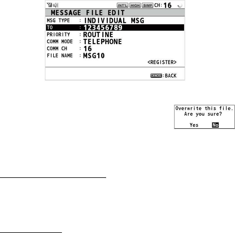
5. MENU OPERATION
5-16
5. Rotate the CHANNEL/ENTER knob to select [DIRECT INPUT], [ADDRESS
BOOK DATA] or [AIS TARGET DATA] then push the knob.
[DIRECT INPUT]: Enter the MMSI where to send the test message with the nu-
meric keys then push the CHANNEL/ENTER knob.
[ADDRESS BOOK DATA]: Select an MMSI from the [ADDRESS BOOK] (see
section 5.13) then push the CHANNEL/ENTER knob.
[AIS TARGET DATA]: Select an MMSI from the [AIS TARGET LIST] then push
the CHANNEL/ENTER knob.
6. With [FILE NAME] selected, push the CHANNEL/ENTER knob.
7. Enter the file name (max. 20 letters) with the numeric keys then push the CHAN-
NEL/ENTER knob.
8. With [REGISTER] selected, push the CHANNEL/ENTER knob.
5.14.6 How to edit prepared messages
1. Open the [MESSAGE FILE] list.
2. Rotate the CHANNEL/ENTER knob to select the message file to edit then push
the knob.
3. Push the CHANNEL/ENTER knob to open the [MESSAGE FILE EDIT] screen.
4. Rotate the CHANNEL/ENTER knob to select the item to edit then push the knob.
5. Change the setting accordingly.
6. Rotate the CHANNEL/ENTER knob to select [REGIS-
TER] then push the knob.
7. Rotate the CHANNEL/ENTER knob to select [Yes] then
push the knob.
5.14.7 How to send prepared messages
How to send without modification
1. Open the [MESSAGE FILE] list.
2. Rotate the CHANNEL/ENTER knob to select the message file desired then press
the OTHER DSC MSG key.
3. Rotate the CHANNEL/ENTER knob to select [GO TO CALL] then push the knob.
Edit before sending
Follow the procedure in paragraph 5.14.6 and do the above procedure "How to send
without modification".
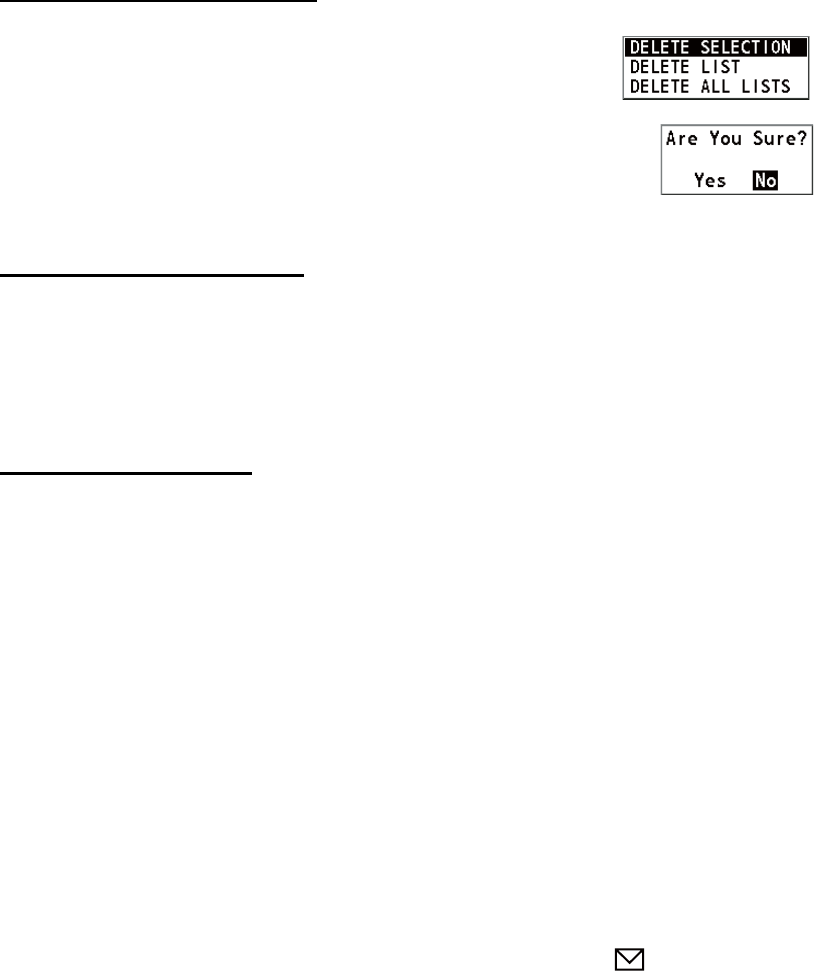
5. MENU OPERATION
5-17
5.14.8 How to delete prepared messages
Open the [MESSAGE FILE] list then follow the applicable procedure below.
Individual prepared message
1. Rotate the CHANNEL/ENTER knob to select the file to de-
lete then press the 4 key.
2. Rotate the CHANNEL/ENTER knob to select [DELETE SE-
LECTION] then push the knob.
3. Rotate the CHANNEL/ENTER knob to select [Yes] then push the knob.
Prepared messages by type
1. Press the 6 key several times to select the desired type.
2. Press the 4 key.
3. Rotate the CHANNEL/ENTER knob to select [DELETE LIST] then push the knob.
4. Rotate the CHANNEL/ENTER knob to select [Yes] then push the knob.
All prepared messages
1. Press the 4 key.
2. Rotate the CHANNEL/ENTER knob to select [DELETE ALL LISTS] then push the
knob.
3. Rotate the CHANNEL/ENTER knob to select [Yes] then push the knob.
5.15 Log File
Three logs are provided for storage of calls:
• [RX DISTRESS] (received distress log)
• [RX GENERAL] (received ordinary log)
• [TX] (transmitted log)
Each mode stores 50 calls. The latest call is saved as log no.1 and the log no. of all
previous calls in that log increments by one. When the storage capacity is exceeded,
the oldest call is deleted to make a room for the latest. The icon ( ) indicates unread
calls. Received distress calls are automatically deleted after 48 hours.
5.15.1 How to open a log file
The procedure to open a log is common to all logs.
1. Rotate the CHANNEL/ENTER knob to select [DSC] on the [MENU] screen then
push the knob.
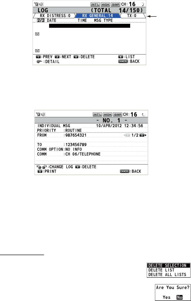
5. MENU OPERATION
5-18
2. Rotate the CHANNEL/ENTER knob to select [LOG] then push the knob.
3. Press the 6 key to switch the log file mode in the sequence of [RX DISTRESS] →
[RX GENERAL] → [TX] → [RX DISTRESS] → ...
4. When there are multiple pages, press the 1 key for the previous page and the 3
key for the next page. Rotate the CHANNEL/ENTER knob to select a desired log
then push the knob. The contents of the selected log file are displayed. To return
to the [MENU] screen, press the CANCEL key.
5. Press the 1 key for the previous page and the 3 key for the next page. Rotate the
CHANNEL/ENTER knob to change the log file (clockwise rotation: to the next log
file, counterclockwise rotation: to the previous log file).
6. To print the selected log, press the 5 key.
7. To return to the log list, press the CANCEL key.
5.15.2 How to delete log files
You can delete the log files except RX DISTRESS. Open the log file list then follow the
applicable procedure below.
Individual log file
1. Rotate the CHANNEL/ENTER knob to select the log file to
delete then press the 4 key.
2. Rotate the CHANNEL/ENTER knob to select [DELETE SE-
LECTION] then push the knob.
3. Rotate the CHANNEL/ENTER knob to select [Yes] then push
the knob.
You can delete a log file by pressing the 4 key on the screen shown at step 4 in
paragraph 5.15.1.
Mode
8 : 15/APR/2012 23:09 INDIVIDUAL MSG
9 : 14/APR/2012 23:05 GROUP MSG
10 : 10/APR/2012 21:15 ALL SHIP MSG
11
: 09/APR/2012 10:32 INDIVIDUAL MSG
12 : 05/APR/2012 09:40 GROUP MSG
13 : 04/APR/2012 14:58 INDIVIDUAL MSG
14 : 01/APR/2012 17:21 INDIVIDUAL MSG
RX GENERAL LOG
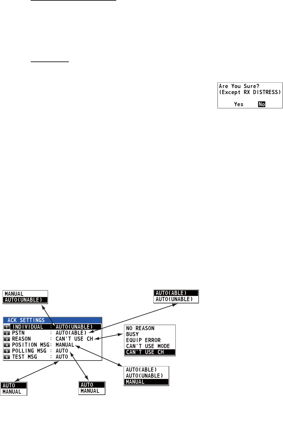
5. MENU OPERATION
5-19
Specify log files by mode
1. Press the 6 key several times to select [RX GENERAL] or [TX].
2. Press the 4 key.
3. Rotate the CHANNEL/ENTER knob to select [DELETE LIST] then push the knob.
4. Rotate the CHANNEL/ENTER knob to select [Yes] then push the knob.
All log files
1. Press the 4 key.
2. Rotate the CHANNEL/ENTER knob to select [DELETE
ALL LISTS] then push the knob.
3. Rotate the CHANNEL/ENTER knob to select [Yes]
then push the knob.
The log files are renumbered to reflect the deletion.
5.16 How to Set the AUTO ACK Details
The acknowledgement message can be sent automatically when you receive an indi-
vidual message or a PSTN message. You can also enable or disable it for position,
polling and test messages. For PSTN, position and polling messages, automatic ac-
knowledge is disabled when there is an active DSC session.
Note 1: For individual message, the automatic acknowledgement is automatically dis-
abled, as required by law, when an RX call contains errors.
1. Rotate the CHANNEL/ENTER knob to select [DSC] on the [MENU] screen then
push the knob.
2. Rotate the CHANNEL/ENTER knob to select [ACK SETTINGS] then push the
knob.
Default:
[AUTO (UNABLE)]
[AUTO (ABLE)]: Send
ABLE acknowledgement
automatically.
[AUTO (UNABLE)]: Send
UNABLE
acknowledgement
automatically.
Sets reason for UNABLE. This menu
item is only for use with PSTN.
Default: [MANUAL]
[AUTO (ABLE)]: When the position
information is set, send automatic
acknowledgement of position request.
When the position information is not set,
send automatic acknowledgement of no
position information (ALL 9).
[AUTO (UNABLE)]: Send automatic
acknowledgement of no position
information (symbol No.126).
[MANUAL]: Send manual
acknowledgement.
Default: [AUTO]
[AUTO]: Send automatic
acknowledgement of polling
request.
[MANUAL]: Send manual
acknowledgement of polling
request.
Default:
[AUTO]
[AUTO]: Send automatic
acknowledgement of test
call.
[MANUAL]: Send manual
acknowledgement of test
call.
Default: [CAN’T USE CH]
Default:
[AUTO (ABLE)]
If you cannot use the
channel or mode
specified by a sending
station, [CAN'T USE CH]
is automatically sent.
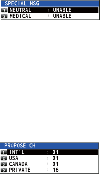
5. MENU OPERATION
5-20
5.17 Special Messages
Permission to transmit NEUTRAL CRAFT and MEDICAL TRANSPORT is enabled or
disabled as follows:
1. Rotate the CHANNEL/ENTER knob to select [DSC] on the [MENU] screen then
push the knob.
2. Rotate the CHANNEL/ENTER knob to se-
lect [SPECIAL MSG] then push the knob.
3. Rotate the CHANNEL/ENTER knob to select [NEUTRAL] or [MEDICAL] then
push the knob.
4. Rotate the CHANNEL/ENTER knob to select [ABLE] or [UNABLE] then push the
knob.
5.18 Propose Channel Setting
When sending the automatic ACK to the PSTN call with no channel specified, your
ship is required to propose a working channel. This proposal can be set as follows:
1. Rotate the CHANNEL/ENTER knob to select [DSC] on the [MENU] screen then
push the knob.
2. Rotate the CHANNEL/ENTER knob to select
[PROPOSE CH] then push the knob.
3. Rotate the CHANNEL/ENTER knob to select the channel region then push the
knob.
4. Rotate the CHANNEL/ENTER knob to select the channel then push the knob.
5.19 Sound Setting
The [AUDIO] menu lets you set the volume for the following items:
• Key click on (setting: [1] - [3]) or off (setting: [0]) (Two beeps sound when a key in-
operative in the ON mode (setting: [1] - [3]) is operated.)
• Speaker on or off with off hook for handset
• Speaker on or off for terminals except in-use one
• Volume of the receiving alarm for the safety and routine messages
• Adjust tone quality for speaker
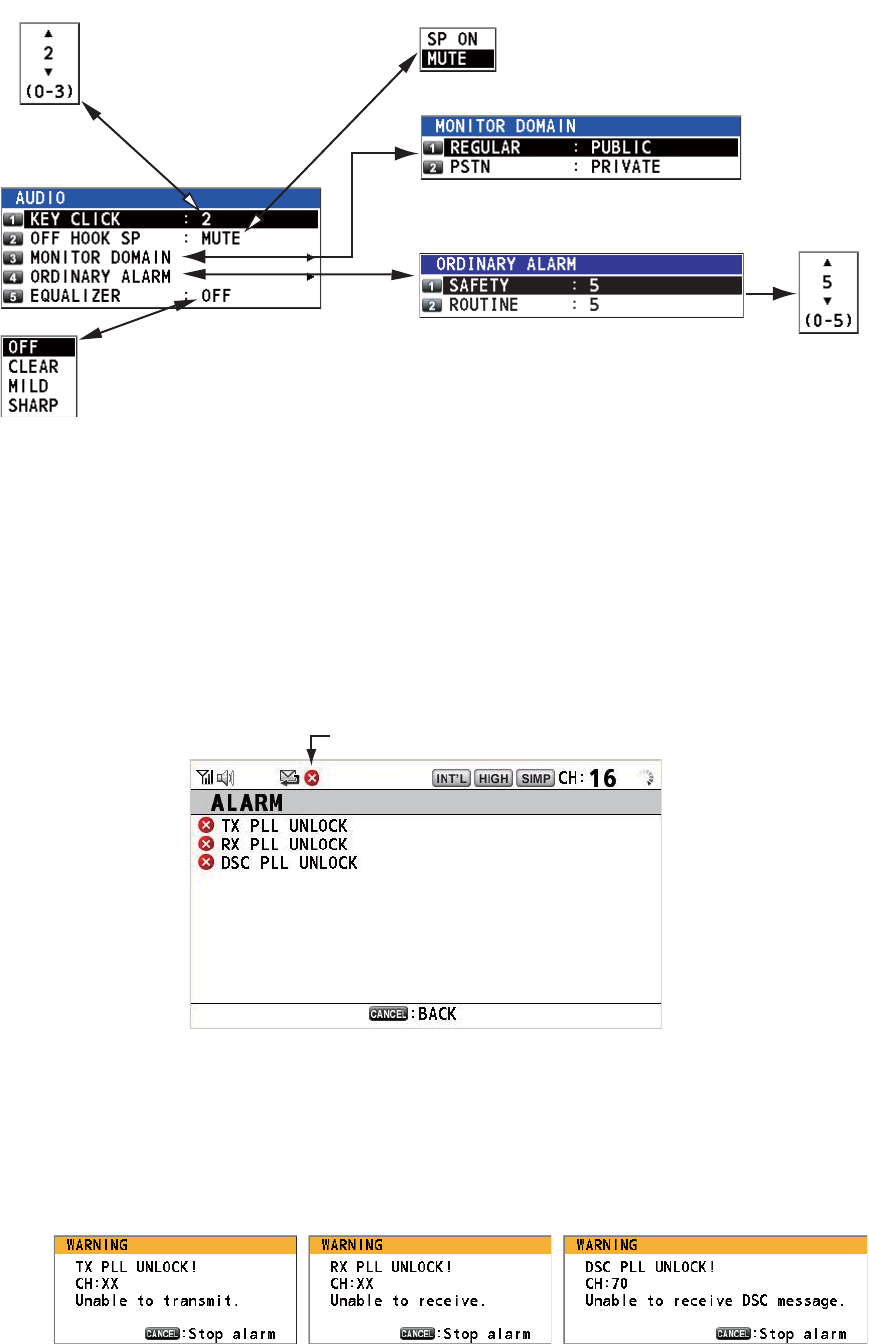
5. MENU OPERATION
5-21
Rotate the CHANNEL/ENTER knob to select [AUDIO] on the [MENU] screen then
push the knob.
5.20 Alarm Lists
The [ALARM] menu shows all currently violated alarms. When an error occurs, a pop-
up message and a flashing error icon appear on the screen. Press the CANCEL key
to close the pop-up message and stop the flashing of the error icon. When the error is
removed, the error icon disappears.
Rotate the CHANNEL/ENTER knob to select [ALARM] on the [MENU] screen then
push the knob. The following screen appears.
There are three kinds of errors: [TX PLL UNLOCK], [RX PLL UNLOCK], [DSC PLL
UNLOCK].
Errors are displayed in the order shown above, not in the order of occurrence. An error
is deleted from the list when the cause for the error is removed.
These alarms are listed when the following messages appear.
Default: [2]
Turn beep on (setting: [1] - [3])
or off (setting: [0]) when a key
is pressed.
Default: [MUTE]
Turn the speaker on or off
when the handset is off hook.
Rotate the CHANNEL/ENTER knob to set volume
then push the knob.
Default: [OFF]
Adjust tone quality for speaker.
Turn the speakers except in-use one on or off.
[PUBLIC]: On, [PRIVATE]: Off
Error icon
5. MENU OPERATION
5-22
This page is intentionally left blank.
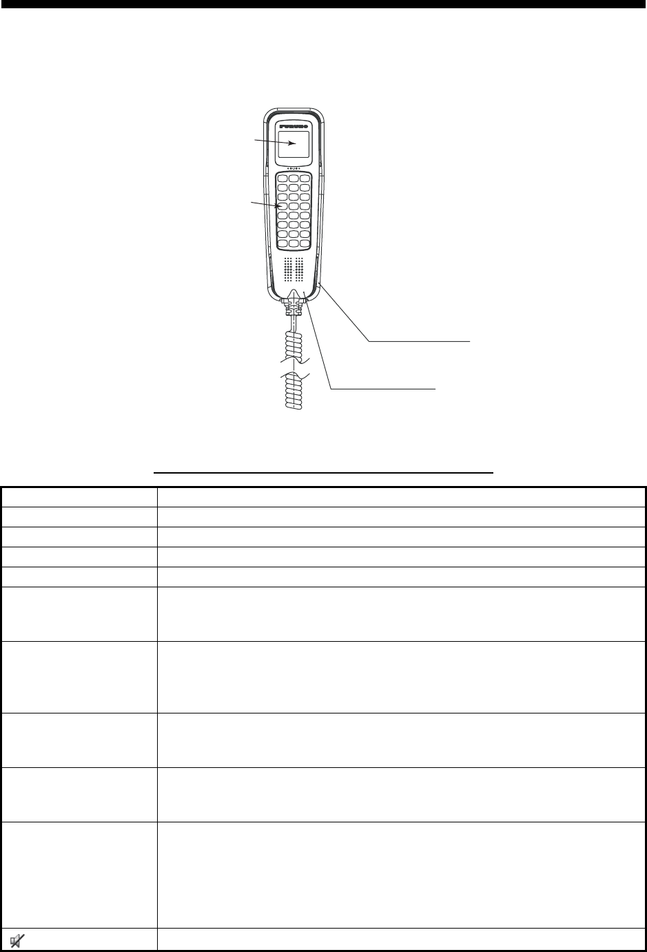
6-1
6. REMOTE HANDSET
6.1 Controls
Remote station RB-8900(-W) (option)
Description of controls for remote station (handset)
Control Function
DW key Turns the DW function on or off (see section 1.9).
HI/LO key Changes the output power to high (25 W) or low (1 W).
CH16 key Switches to the RT (radiotelephone) screen and sets CH16.
SCAN key Turns the scan function on or off (see section 1.10).
S, T keys • Selects the menu items.
• Selects the channel on the RT screen.
• Adjusts the setting values.
SQ key Adjusts the squelch. Press the SQ key on the RT/OCCUPIED screen then
press the S or T key within three seconds to adjust the squelch (setting
range: AUTO, 0 to 10). To get auto squelch adjustment, press the T key
with the setting 0 (indication: SQA).
VOL key Adjusts the volume. Press the VOL key on the RT/OCCUPIED screen then
press the S or T key within three seconds to adjust the volume (setting
range: 0 to 10).
ENTER key • Moves down one layer when you save the menu option in a layer other
than the lowest one. In the undermost layer, opens the setting window.
• Confirms a selection.
CANCEL key • Silences the audio alarm.
• Returns one layer in a multi-layer menu. In the top layer, closes the menu
then displays the RT screen.
• Cancels the setting in the setting window then goes back one layer in the
menu.
• Cancels the intercom call.
key Turns the loudspeaker on or off.
HS-8900(-W)
Remote handset
LCD
Keyboard
HG-8900(-W)
Handset hanger
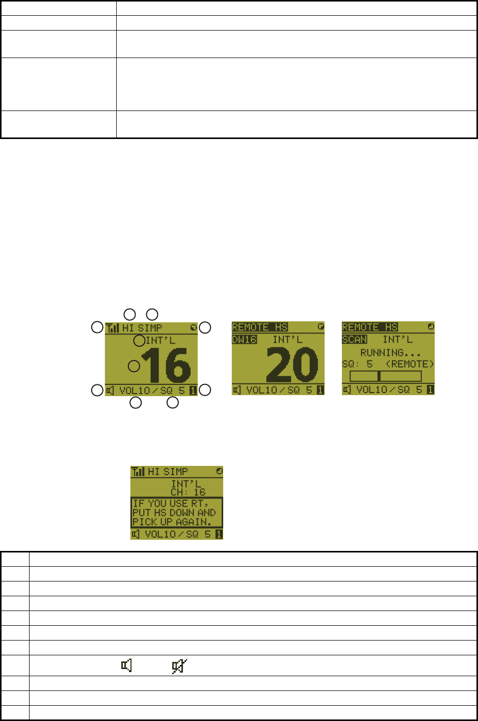
6. REMOTE HANDSET
6-2
6.2 How to Turn On/Off the Power
A handset does not have a power key. Turn on or off the power from the transceiver
unit.
6.3 Radiotelephone (RT) Screen
Below are the radiotelephone (RT) screens on the remote handset.
MENU key Opens/closes the menu.
0 to 9 keys • Enters the channel on the RT screen.
• Selects the menu items.
CONTRAST key Short press: Opens the contrast setup screen. Press the S or T key to
adjust the contrast.
Long press (more than three seconds): Restores the contrast to the de-
fault setting.
BRILL key Opens the brill setup screen. Press the S or T key to adjust the brill. You
can also use the BRILL key.
No. Meaning
1 RX signal strength (This icon does not appear while transmitting.)
2 Output power ([HI]: High, [LO]: Low)
3 Channel type ([SIMP]: Simplex, [DUP]: Duplex)
4 Spinner rotates when the equipment is functioning normally.
5 Channel region ([INT’L], [USA], [CANADA], [INLAND-W], [PRIVATE])
6 Channel
7Loudspeaker on ( ) or off ( )
8 Volume for loudspeaker (0 to 10)
9 Squelch level (0 to 10, AUTO (Indication is [SQA].))
10 Terminal ID ([L]: Left wing handset, [R]: Right wing handset, [1] to [4]: Remote handset 1 to 4)
Control Function
2
1
3
4
5
9
10
6
7
8DW screen
Common RT screen
Scan screen
When no terminal has operation right and a remote handset is off hook,
the following screen appears.
A remote handset can get the
operation right if you hook on
then hook off.
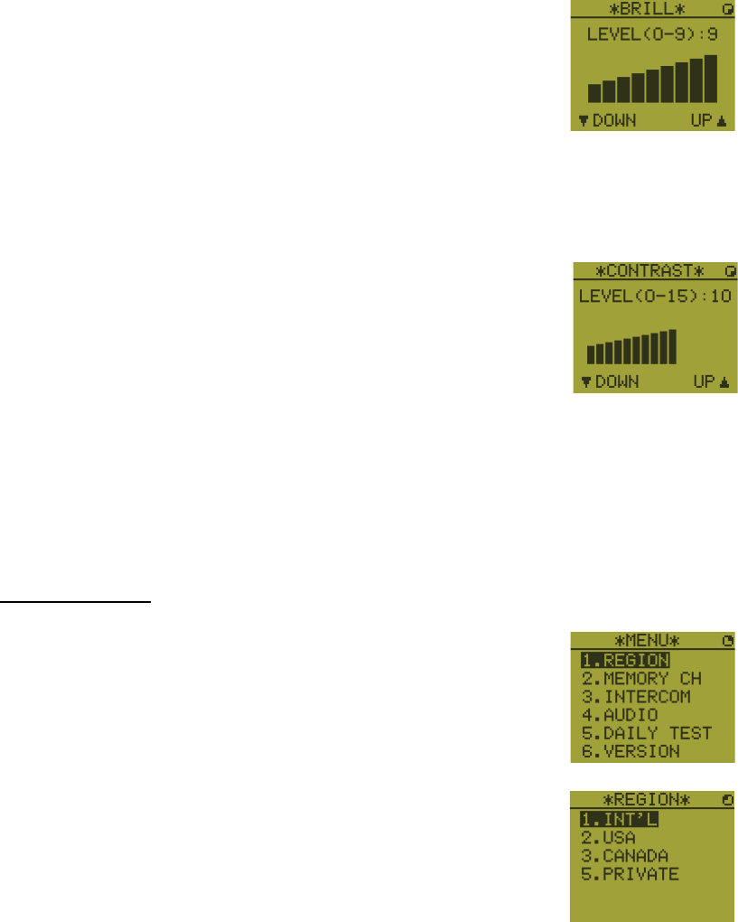
6. REMOTE HANDSET
6-3
6.4 How to Adjust the Brilliance and Contrast
You can adjust the brilliance of the display and the panel for each remote handset sep-
arately. Also, you can adjust the contrast for each remote handset.
Brilliance
1. Press the BRILL key to show the [BRILL] setting window.
2. Press the S or T key to adjust the brilliance.
3. Press the ENTER key to save the settings and close the
window. To cancel the settings, press the CANCEL key in-
stead of the ENTER key to close the window.
Note: The [BRILL] setting window automatically closes when there is no menu oper-
ation for three seconds.
Contrast
1. Press the CONTRAST key to show the [CONTRAST] set-
ting window.
2. Press the S or T key to adjust the contrast.
3. Press the ENTER key to save the settings and close the
window. To cancel the settings, press the CANCEL key in-
stead of the ENTER key to close the window.
Note: The [CONTRAST] setting window automatically closes when there is no menu
operation for three seconds.
6.5 How to Select the Channel Region, Channel
Channel region
1. Press the MENU key to open the [MENU] screen.
2. Press the S or T key to select [REGION] then press the
ENTER key.
3. Press the S or T key to select the channel mode desired then press the ENTER
key. The following modes are available.
• [INT’L]: International mode
• [USA]: USA mode
• [CANADA]: CANADA mode
• [INLAND-W]: Inland waterway mode
• [PRIVATE]: Private channel
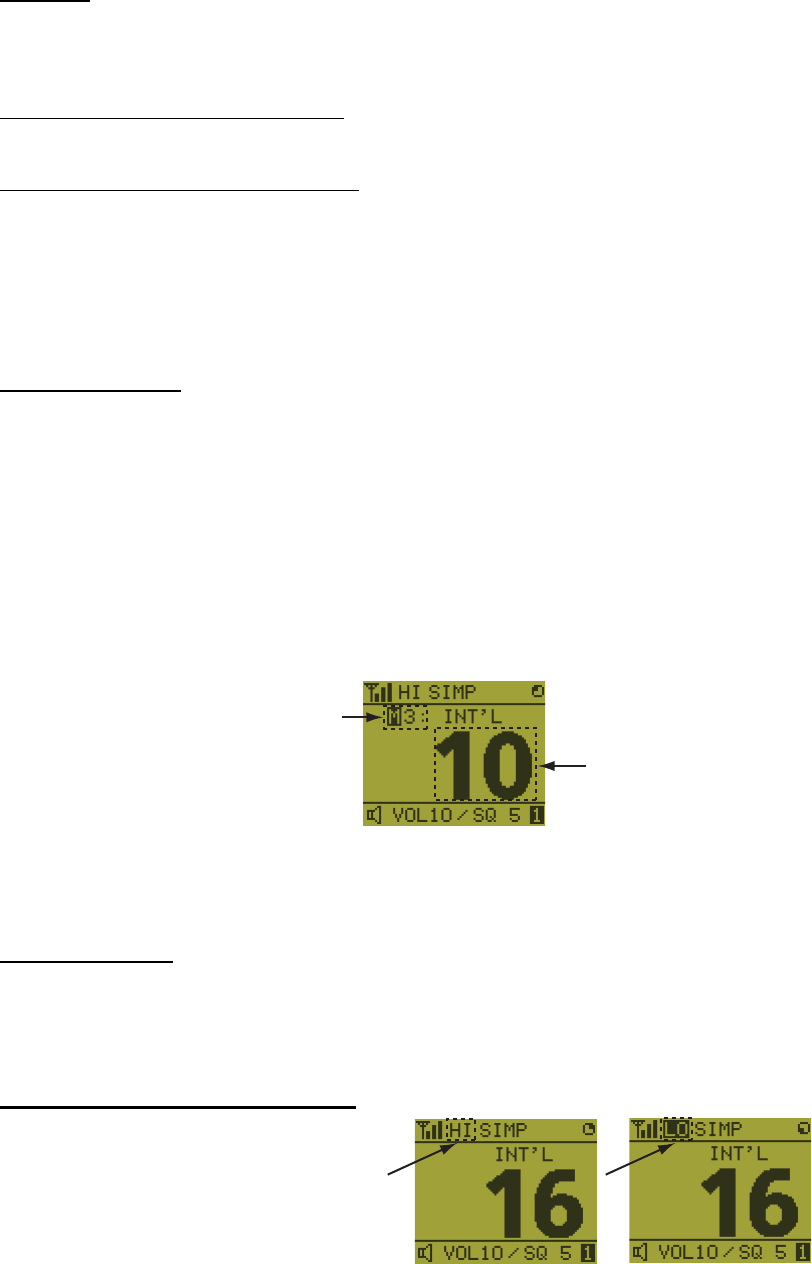
6. REMOTE HANDSET
6-4
Note 1: Only permitted channel regions are displayed, which are set by the install-
er of the equipment.
Note 2: Private channels are available only where permitted by the authorities.
The [USA], [CANADA], [INLAND-W], [PRIVATE] can also be set by a qualified
service technician.
Channel
The channel can be set manually on the RT screen. Enter the channel by one of the
methods below.
Enter channel with the S or T key:
Press the S or T key on the RT screen.
Enter channel with the numeric keys:
Use the numeric keys to enter channel on the RT screen. (It is not necessary to press
the ENTER key after entering the channel; the setting is confirmed one second after
it is entered.)
Note: When the transceiver unit is in on hook condition, you can change the channel
with the remote handset.
Memory channel
You can easily call up a channel which you registered in the transceiver unit as a mem-
ory channel (see section 5.4).
1. Press the MENU key to open the [MENU] screen.
2. Press the S or T key to select [MEMORY CH] then press the ENTER key.
3. Press the S or T key to select [ON] or [OFF] then press the ENTER key.
When you select [ON], "M" appears on the screen. On the RT screen, you can se-
lect a memory channel by pressing the S or T key. The following figure shows
the example for CH 10.
6.6 Transmission
How to transmit
Press the PTT (Push-to-talk) switch on the handset to talk, and release it to listen for
a response. "TX" appears at the top left-hand corner of the screen during transmis-
sion.
How to change the output power
Press the HI/LO key to change the
output power to high and low alter-
nately. "HI" or "LO" appears on the
screen depending on your selection.
Channel number
“3” means that you turned 3
channels of the selected
channel region to [ON] in
the [MEMORY CONFIG]
menu in the transceiver unit.
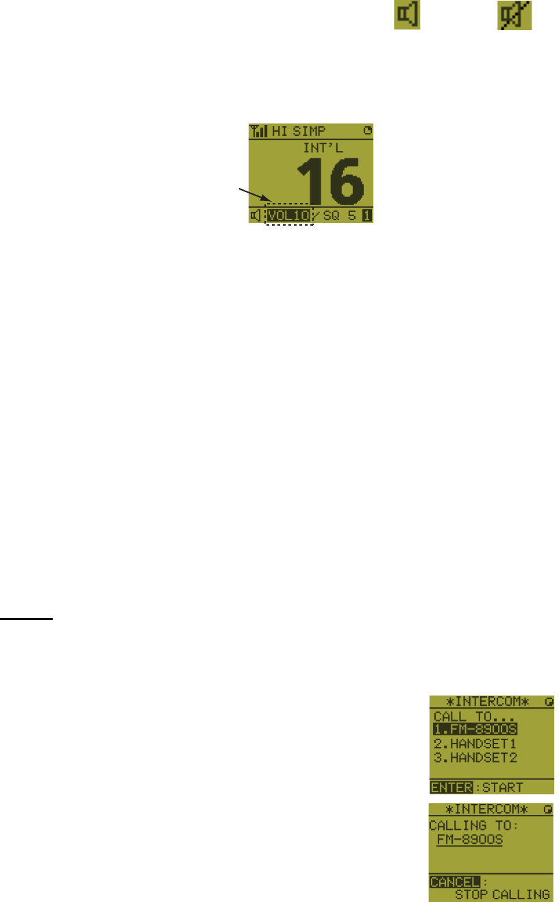
6. REMOTE HANDSET
6-5
6.7 How to Turn On/Off the Loudspeaker
You can turn the loudspeaker (other than DSC communication, error, and key beep)
on or off.
1. Press the SPK key to alternately disable or en-
able the loudspeaker.
2. To adjust the volume of the loudspeaker, press the VOL key. The screen changes
as below.
3. Press the S or T key to adjust the volume within three seconds. The time for re-
verse highlighting is three seconds.
6.8 Quick Selection of CH16
Press the CH16 key to select CH16. The CH16 (156.8 MHz) is the international fre-
quency for distress traffic and for calling by radiotelephone. The CH16 can also be
used by ship stations for call and reply. To facilitate the reception of distress calls and
distress traffic, all transmissions on CH16 should be kept to a minimum and should not
exceed one minute. Before transmitting on the CH16, a station should listen on this
frequency for a reasonable period to make sure that no distress traffic is being sent.
6.9 Intercom
The built-in intercom permits voice communications between two control units. The
combination of two controls is transceiver unit & remote handset, or remote handset
& remote handset.
Calling
You can call over the intercom only in off hook condition.
1. Press the MENU key to open the [MENU] screen.
2. Press the S or T key to select [INTERCOM] then press
the ENTER key.
3. Press the S or T key to select the called party’s control
unit then press the ENTER key.
The called party’s control unit and yours ring.
To cancel calling, press the CANCEL key.
Speaker ON Speaker OFF
Reverse highlighting
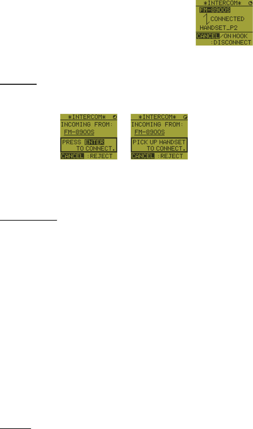
6. REMOTE HANDSET
6-6
4. When the called party picks up their handset, the screen
as shown in the right figure appears. Start communica-
tions.
Note: You do not have to press the PTT switch to commu-
nicate.
5. Hang up the handset or press the CANCEL or the CH16 key to turn the intercom
off. The RT screen appears.
Answering
1. The control unit rings and the following screen appears. To cancel reply, press the
CANCEL key.
2. Press the ENTER key with off hook condition or pick up the handset with on hook
condition to start communications.
3. Hang up the handset or press the CANCEL key to turn the intercom off. The RT
screen appears.
Earpiece volume
You can adjust the volume of the earpiece during intercom communication by pressing
the S or T key. After intercom communication, the earpiece volume is reverted to the
setting value you set on [EARPIECE LEVEL] (see section 6.11).
Note: Neither key click nor key error sounds during intercom communication.
6.10 How to Change the Terminal ID
1. Turn off the remote handset by the transceiver unit.
2. While you hold the MENU key, turn on the remote handset by the transceiver unit.
The setting window for terminal ID appears.
3. Enter the terminal ID, using the 1 to 6 keys, then press the ENTER key. Do not
assign the same number to multiple remote stations.
Note: Restart the remote handset by the transceiver unit after changing terminal ID.
6.11 Audio setting
The [AUDIO] menu enables or disables key beep and adjusts the volume of the ear-
piece and off hook loudspeaker.
Key click
1. Press the MENU key to open the [MENU] screen.
Off hook condition On hook condition
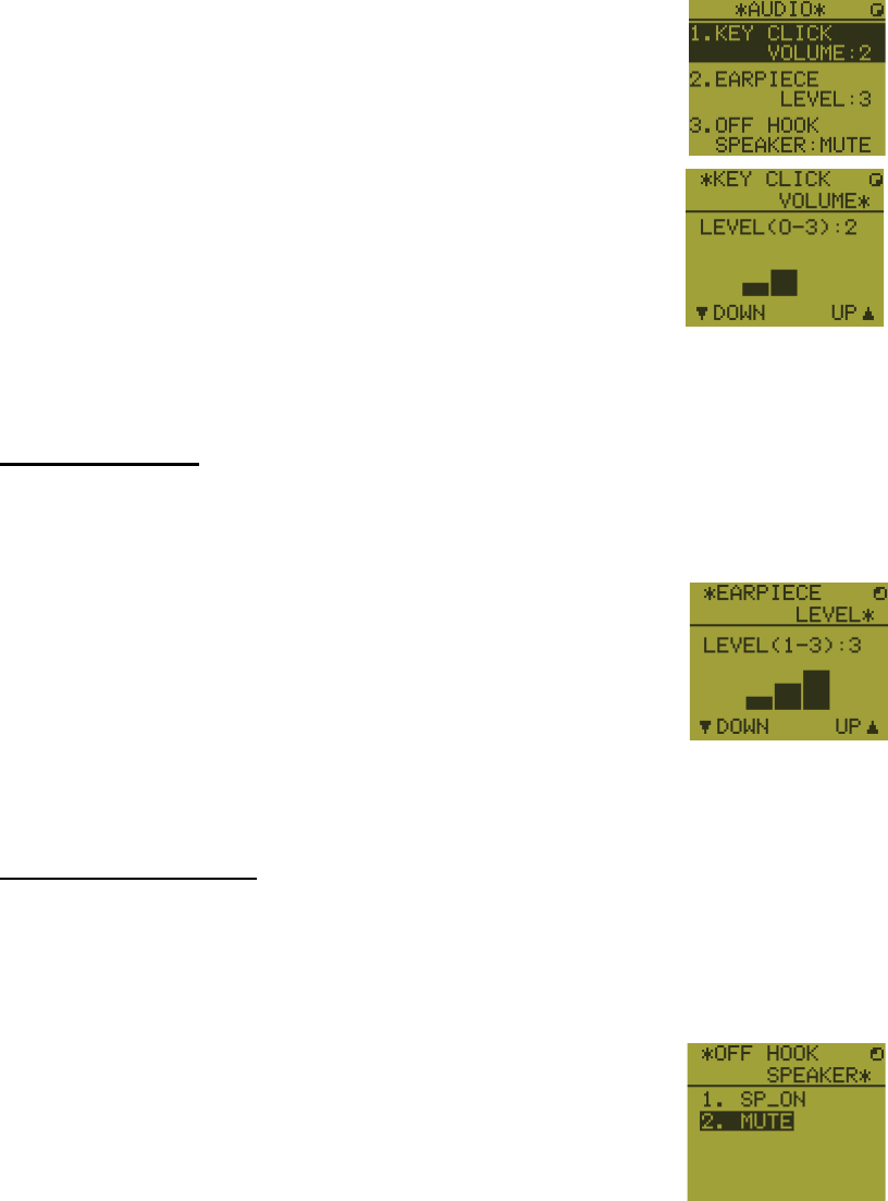
6. REMOTE HANDSET
6-7
2. Press the S or T key to select [AUDIO] then press the EN-
TER key.
3. Press the S or T key to select [KEY CLICK VOLUME] then
press the ENTER key.
4. Press the S or T key to set the key click level (setting range: 0 (OFF), 1, 2 or 3).
5. Press the ENTER key. To cancel the setting, press the CANCEL key.
Earpiece volume
1. Press the MENU key to open the [MENU] screen.
2. Press the S or T key to select [AUDIO] then press the ENTER key.
3. Press the S or T key to select [EARPIECE LEVEL] then
press the ENTER key.
Note: Neither key click nor key error sounds during the
[EARPIECE LEVEL] display.
4. Press the S or T key to set the earpiece volume level (setting range: 1 to 3).
5. Press the ENTER key. To cancel the setting, press the CANCEL key.
Off hook loudspeaker
You can set the loudspeaker on or off according to off hook condition.
1. Press the MENU key to open the [MENU] screen.
2. Press the S or T key to select [AUDIO] then press the ENTER key.
3. Press the S or T key to select [OFF HOOK SPEAKER]
then press the ENTER key.
4. Press the S or T key to select [SP_ON] or [MUTE].
[SP_ON]: Loudspeaker is activated when off hook.
[MUTE]: Loudspeaker is deactivated when off hook.
5. Press the ENTER key. To cancel the setting, press the CANCEL key.
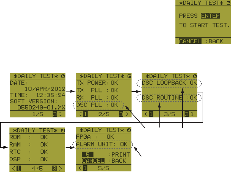
6. REMOTE HANDSET
6-8
6.12 How to Test FM-8900S from a Remote Handset
1. Press the MENU key to open the [MENU] screen.
2. Press the S or T key to select [DAILY TEST] then press
the ENTER key.
3. Press the ENTER key to start the test. You can confirm the test results for FM-
8900S with the 1 or 3 key.
6.13 How to Display the Program Versions
1. Press the MENU key to open the [MENU] screen.
2. Press the S or T key to select [VERSION] then press the ENTER key. The pro-
gram versions for FM-8900S and HS-8900 appear.
6.14 Squelch
• The squelch value is common to all remote handsets. If you change a squelch value
for a remote handset, squelch values for all other remote handsets are changed ac-
cordingly.
• You can not change a squelch value for a remote handset while the squelch is being
adjusted by another remote handset.
• When the DW or scan is active, the squelch value from the terminal (transceiver unit
or remote handset) that initiated the DW or scan is used.
This item is not displayed when
there is no alarm unit.
Press the 3 key for the next page and the 1 key for the previous page.
These items are displayed
only when entering own
ship’s MMSI.
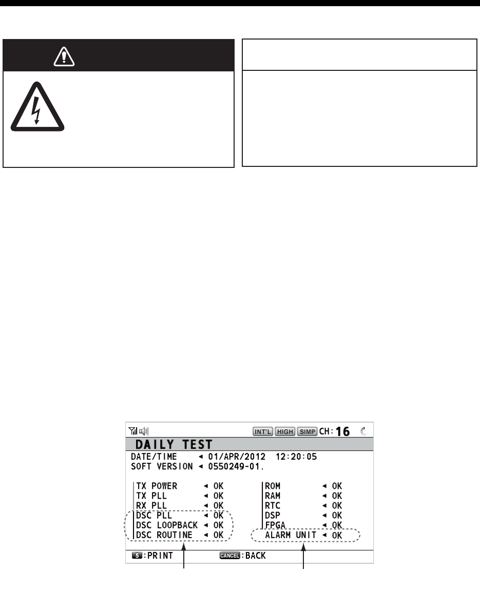
7-1
7. MAINTENANCE &
TROUBLESHOOTING
7.1 Daily Test
Do the daily test to check the radiotelephone for proper operation.
Rotate the CHANNEL/ENTER knob to select [TEST] on the [MENU] screen then push
the knob. The daily test starts. After the test is completed, the audio alarm sounds and
the screen shown below appears. This screen shows:
• Test date
• Program version number
• Test results for TX power, TX PLL, RX PLL, DSC PLL, DSC loopback, DSC routine,
ROM, RAM, RTC, DSP, FPGA and alarm unit (only when connecting the alarm
unit), shown as [OK] or [NG] (No Good). For NG, contact your dealer for advice. The
DSC test checks, using a DSC signal, the encode and decode functions of the sig-
nal processor.
To print out the test result manually, press the 5 key. Automatic printing of the daily
test is available. See section 5.5.
Do not apply paint, anti-corrosive sealant
or contact spray to plastic parts or
equipment coating.
Those items contain products that can
damage plastic parts and equipment coating.
ELECTRICAL SHOCK HAZARD
Do not open the equipment.
Only qualified personnel
should work inside the
equipment.
WARNING
WARNING
NOTICE
x
x
This item is not available
when not connecting the
alarm unit.
These items are not
available when not enter-
ing own ship’s MMSI.

7. MAINTENANCE & TROUBLESHOOTING
7-2
7.2 Maintenance
Regular maintenance helps to keep your equipment in good condition and prevents
future problems. Check the items shown in the table below.
7.3 Simple Troubleshooting
The table below provides possible problems and the means with which to restore nor-
mal operation. If normal operation cannot be restored, do not attempt to check inside
the equipment. Any servicing should be referred to a qualified technician.
Item Check point Remedy/Remarks
Antenna Check for physical damage and corrosion. Replace damaged parts.
Wire
antenna
Check that the antenna is properly spanned
and separated sufficiently from metallic
structures.
If necessary, re-span antenna.
Insulators
for antenna
Check for salt water deposits on insulators.
Check that connection at the lead-in insula-
tor is tight and rust-free.
Replace damaged insulator(s). Remove
salt water deposits. Clean with fresh
water, then dry. Remove rust, then
tighten bolts and lock nuts. Cover me-
tallic surface with sealing compound.
Transceiver
unit
• Check ground connection.
• Check connection at signal cable, coaxial
cable, control cable, power cable and ex-
ternal equipment (including navigator).
• Confirm that there are no objects on the
top of the transceiver unit.
• Remove dust from transceiver unit with
soft cloth.
Note: Do not use chemical cleaners to
clean the transceiver unit; they can remove
paint or markings and deform the equip-
ment.
• Tighten the loosened connections;
remove foreign materials from con-
nectors.
• Remove any objects.
• Wipe the LCD carefully to prevent
scratching, using tissue paper and an
LCD cleaner. To remove dirt or salt
deposits, use an LCD cleaner, wiping
slowly with tissue paper so as to dis-
solve the dirt or salt. Change paper
frequently so the salt or dirt does not
scratch the LCD.
Power
supply
Check that the supply voltage at transmis-
sion is within the rated range (21.6 to 31.2
VDC at the power connector).
If not within the range, check power
source. Low voltage may cause erratic
operation.
Power fuse Check if a power fuse (7A) has blown. If the fuse has blown, find out the cause
before replacing it (Type: FGBO 125V
7A PBF). If it blows after replacement,
contact your dealer.
Problem Probable cause Remedy
Power cannot be
turned on.
• Mains switchboard is off.
• (DC) voltage is too high or too low.
• Battery has discharged, or poor
contact at terminals.
• Turn on the mains switchboard.
• Check supply voltage.
• Recharge the battery and tighten
the battery terminals.
Display indications
do not appear.
Display brilliance is too low. Press the BRILL key to adjust the
display brilliance.
Power is on but no
sound from the main
speaker.
Main speaker is off. Press the key to turn on the main
speaker.
Output power re-
duced to LOW
Power is automatically reduced to pro-
tect against overheating due to contin-
uous transmission.
Wait until the unit cools.
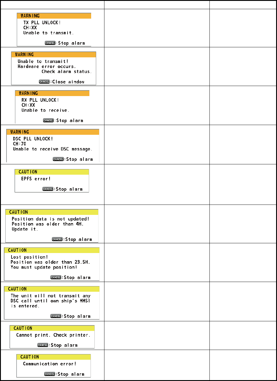
7. MAINTENANCE & TROUBLESHOOTING
7-3
7.4 Warning and Caution Messages
The table below shows error messages, their meanings, and remedies. To delete the
messages, press the CANCEL key.
Message Meaning Remedy
TX PLL unlock. Transmission is dis-
abled.
Contact your dealer.
TX PLL unlock error. Transmission is
disabled.
Contact your dealer.
RX PLL unlock. Reception is dis-
abled.
Contact your dealer.
DSC (CH70) PLL unlock. Contact your dealer.
Position data is not input for ten min-
utes.
Note: This message does not ap-
pear when [INPUT TYPE] in the [PO-
SITION] menu is set to [MANUAL].
Enter the position.
Position data has not been updated
for 4H.
Enter the position.
Position data has not been updated
for 23.5H.
Enter the position.
You tried to send a DSC message
but your MMSI has not been regis-
tered in the equipment.
Enter MMSI no. of
your ship.
Printer trouble. Cannot print. Check the printer
(connection, power,
paper).
Communication between the trans-
ceiver unit and a remote handset is
lost for three seconds.
Check the connection
with the remote hand-
set. If unsolved, con-
tact your dealer.
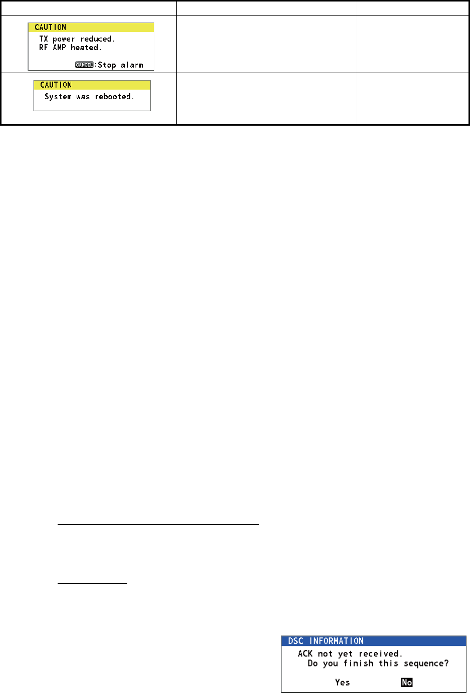
7. MAINTENANCE & TROUBLESHOOTING
7-4
7.5 Test Call
This function sends a test signal to a coast or ship station. For that reason, it should
not be executed unnecessarily. You can prepare a test call beforehand (see
paragraph 5.14.5).
1. Press the OTHER DSC MSG key to open the [COMPOSE MESSAGE].
2. Rotate the CHANNEL/ENTER knob to select [MSG TYPE] then push the knob.
3. Rotate the CHANNEL/ENTER knob to select [TEST MSG] then push the knob.
[PRIORITY] is automatically set to [SAFETY].
4. With [TO] selected, push the CHANNEL/ENTER knob.
5. Rotate the CHANNEL/ENTER knob to select [DIRECT INPUT], [ADDRESS
BOOK DATA] or [AIS TARGET DATA] then push the knob.
[DIRECT INPUT]: Enter the MMSI of the station where to send the call then push
the CHANNEL/ENTER knob.
[ADDRESS BOOK DATA]: Select an MMSI from the [ADDRESS BOOK] (see
section 5.13) then push the CHANNEL/ENTER knob.
[AIS TARGET DATA]: Select an MMSI from the [AIS TARGET LIST] then push
the CHANNEL/ENTER knob.
6. With [GO TO CALL] selected, push the CHANNEL/ENTER knob to send the test
message. The screen is changed to the one for transmission. After the call is sent,
the equipment waits for acknowledgement of the call. The timer starts counting up
the time to wait for acknowledgement.
7. Do one of the following.
Test acknowledge message received
The audio alarm sounds and the message "TEST ACK received! [CANCEL]: Stop
alarm" appears. Press the CANCEL key to silence the alarm.
No response
Re-send call: Rotate the CHANNEL/ENTER knob to select [RESEND] in the user op-
tions area then push the knob.
Cancel call: Rotate the CHANNEL/ENTER
knob to select [QUIT] in the user options
area then push the knob. The message
shown in the right figure appears.
Rotate the CHANNEL/ENTER knob to se-
lect [Yes] then push the knob.
RF amplifier is too hot. Transmission
power is reduced.
Allow the transceiver
unit to cool. If the mes-
sage appears again,
contact your dealer.
Internal error. System is rebooted. System automatically
restarts. If the problem
occurs again, contact
your dealer.
Message Meaning Remedy
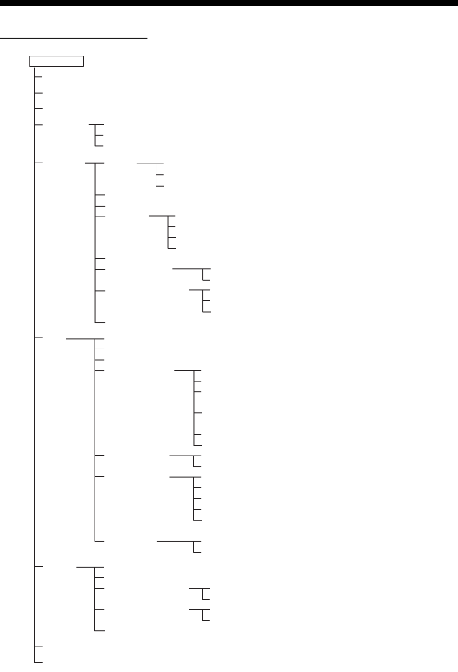
AP-1
APPENDIX 1 MENU TREE
Transceiver unit FM-8900S
MENU key Bold: Default setting
HS VOL (1 - 20, 15)
TEST
INTERCOM
CH MODE
SYSTEM
DSC
AUDIO
ALARM (Open alarm list)
SERVICE (For service technician)
PRINT
POSITION (Open setting window)
DATE/TIME (Open setting window)
TIMEOUT
INTERCOM NAME (Open intercom name editting screen)
AUTO REVERT
EXTERNAL ALARM
RT APPLICATION (GUIDE, HS STATE, SQ METER)
INDIVIDUAL (MANUAL, AUTO (UNABLE))
PSTN (AUTO (ABLE), AUTO (UNABLE))
REASON (NO REASON, BUSY, EQUIP ERROR,
CAN'T USE MODE, CAN'T USE CH)
POSITION MSG (AUTO (ABLE),
AUTO (UNABLE), MANUAL)
POLLING MSG (AUTO, MANUAL)
TEST MSG (AUTO, MANUAL)
ADDRESS BOOK (Open address data list)
MSG FILE (Open message file list)
LOG (Open log data list)
ACK SETTINGS
SPECIAL MSG
PROPOSE CH
MMSI X10*
TX MSG (AUTO, MANUAL)
RX MSG (AUTO, MANUAL)
DAILY TEST (AUTO, MANUAL)
MENU END (10MIN, NO TIMEOUT)
DSC GENERAL (15MIN, NO TIMEOUT)
RX DISTRESS (15MIN, NO TIMEOUT)
TELEPHONE (10SEC, 30SEC, 10MIN)
URGENCY (ON, OFF)
SAFETY (ON, OFF)
ROUTINE (ON, OFF)
NEUTRAL (ABLE, UNABLE)
MEDICAL (ABLE, UNABLE)
INT’L (01 - 88)
USA (01 - 88)
CANADA (01 - 88)
INLAND-W* (01 - 88)
PRIVATE (CH16 and a max. of 19 other channels
selected in the [SERVICE] menu.)
X10 (0 - 9; 0)
MODE (ZERO, NON-ZERO, REJECT)
KEY CLICK (0 - 3; 2)
OFF HOOK SP (SP ON, MUTE)
MONITOR DOMAIN
ORDINARY ALARM
EQUALIZER (OFF, CLEAR, MILD, SHARP)
REGULAR (PUBLIC, PRIVATE)
PSTN (PUBLIC, PRIVATE)
SAFETY (0 - 5; 5)
ROUTINE (0 - 5; 5)
REGION (INT’L, USA, CANADA, INLAND-W*, PRIVATE)
MEMORY (ON, OFF)
MEMORY CONFIG (Open memory config window)
MAIN (RT+DSC, RT, OFF)
REMOTE (ON, OFF)
*: These menu items appear
according to the settings
of the [SERVICE] menu.

APPENDIX 1 MENU TREE
AP-2
Remote handset HS-8900(-W)
MENU key Bold: Default setting
REGION (INT’L, USA, CANADA, INLAND-W*, PRIVATE)
MEMORY CH (ON, OFF)
INTERCOM
AUDIO
DAILY TEST (Display the test results for FM-8900S)
VERSION (Display the program versions for FM-8900S and HS-8900)
KEY CLICK VOLUME (0 (OFF) - 3, 2)
EARPIECE LEVEL (1 - 3, 3)
OFF HOOK SPEAKER (SP_ON, MUTE)
*: This menu item appears according to the setting
of the [SERVICE] menu in the FM-8900S.

AP-3
APPENDIX 2 MARINE VHF CHANNEL
LISTS
International channels
CH TX (MHz) RX (MHz) Remark CH TX (MHz) RX (MHz) Remark
01 156.050 160.650 60 156.025 160.625
02 156.100 160.700 61 156.075 160.675
03 156.150 160.750 62 156.125 160.725
04 156.200 160.800 63 156.175 160.775
05 156.250 160.850 64 156.225 160.825
06 156.300 156.300 65 156.275 160.875
07 156.350 160.950 66 156.325 160.925
08 156.400 156.400 67 156.375 156.375
09 156.450 156.450 68 156.425 156.425
10 156.500 156.500 69 156.475 156.475
11 156.550 156.550 70 156.525 156.525 DSC
12 156.600 156.600 71 156.575 156.575
13 156.650 156.650 72 156.625 156.625
14 156.700 156.700 73 156.675 156.675
15 156.750 156.750 74 156.725 156.725
16 156.800 156.800 75 156.775 156.775 Low PWR
17 156.850 156.850 76 156.825 156.825 Low PWR
18 156.900 161.500 77 156.875 156.875
19 156.950 161.550 78 156.925 161.525
20 157.000 161.600 79 156.975 161.575
21 157.050 161.650 80 157.025 161.625
22 157.100 161.700 81 157.075 161.675
23 157.150 161.750 82 157.125 161.725
24 157.200 161.800 83 157.175 161.775
25 157.250 161.850 84 157.225 161.825
26 157.300 161.900 85 157.275 161.875
27 157.350 161.950 86 157.325 161.925
28 157.400 162.000 87 157.375 157.375
88 157.425 157.425

APPENDIX 2 MARINE VHF CHANNEL LISTS
AP-4
USA channels
*: USCG (United States Coast Guard) only (General use prohibited)
USA weather channels
CH TX (MHz) RX (MHz) Remark CH TX (MHz) RX (MHz) Remark
01 156.050 156.050 60 - -
02 - - 61 - -
03 - - 62 - -
04 - - 63 156.175 156.175
05 156.250 156.250 64 - -
06 156.300 156.300 65 156.275 156.275
07 156.350 156.350 66 156.325 156.325
08 156.400 156.400 67 156.375 156.375 Low PWR
09 156.450 156.450 68 156.425 156.425
10 156.500 156.500 69 156.475 156.475
11 156.550 156.550 70 156.525 156.525 DSC
12 156.600 156.600 71 156.575 156.575 Low PWR
13 156.650 156.650 Low PWR 72 156.625 156.625
14 156.700 156.700 73 156.675 156.675
15 - 156.750 74 156.725 156.725
16 156.800 156.800 75 156.775 156.775 Low PWR
17 156.850 156.850 76 156.825 156.825 Low PWR
18 156.900 156.900 77 156.875 156.875 Low PWR
19 156.950 156.950 78 156.925 156.925
20 157.000 157.000 79 156.975 156.975
21 157.050 157.050 * 80 157.025 157.025
22 157.100 157.100 81 157.075 157.075 *
23 157.150 157.150 * 82 157.125 157.125 *
24 157.200 161.800 83 157.175 157.175 *
25 157.250 161.850 84 157.225 161.825
26 157.300 161.900 85 157.275 161.875
27 157.350 161.950 86 157.325 161.925
28 157.400 162.000 87 157.375 157.375
88 157.425 157.425
WX RX (MHz) WX RX (MHz)
01 162.550 06 162.500
02 162.400 07 162.525
03 162.475 08 161.650
04 162.425 09 161.775
05 162.450 10 163.275

APPENDIX 2 MARINE VHF CHANNEL LISTS
AP-5
Canadian channels
*: DFO/Canadian Coast Guard only
**: For communications between the Coast Guard and non-Coast Guard stations only
Canadian weather channels
CH TX (MHz) RX (MHz) Remark CH TX (MHz) RX (MHz) Remark
01 156.050 160.650 60 156.025 160.625
02 156.100 160.700 61 156.075 156.075
03 156.150 160.750 62 156.125 156.125
04 156.200 156.200 63 156.175 156.175
05 156.250 156.250 64 156.225 160.825
06 156.300 156.300 65 156.275 156.275
07 156.350 156.350 66 156.325 156.325
08 156.400 156.400 67 156.375 156.375
09 156.450 156.450 68 156.425 156.425
10 156.500 156.500 69 156.475 156.475
11 156.550 156.550 70 156.525 156.525 DSC
12 156.600 156.600 71 156.575 156.575
13 156.650 156.650 72 156.625 156.625
14 156.700 156.700 73 156.675 156.675
15 156.750 156.750 Low PWR 74 156.725 156.725
16 156.800 156.800 75 156.775 156.775 Low PWR
17 156.850 156.850 Low PWR 76 156.825 156.825 Low PWR
18 156.900 156.900 77 156.875 156.875
19 156.950 156.950 78 156.925 156.925
20 157.000 161.600 Low PWR 79 156.975 156.975
21 157.050 157.050 * 80 157.025 157.025
22 157.100 157.100 ** 81 157.075 157.075 *
23 157.150 161.750 82 157.125 157.125 *
24 157.200 161.800 83 157.175 157.175 *
25 157.250 161.850 84 157.225 161.825
26 157.300 161.900 85 157.275 161.875
27 157.350 161.950 86 157.325 161.925
28 157.400 162.000 87 157.375 157.375
88 157.425 157.425
WX RX (MHz) WX RX (MHz)
01 162.550 06 162.500
02 162.400 07 162.525
03 162.475 08 161.650
04 162.425 09 161.775
05 162.450 10 163.275

APPENDIX 2 MARINE VHF CHANNEL LISTS
AP-6
Inland waterways (INLAND-W) channels
CH TX (MHz) RX (MHz) Remark CH TX (MHz) RX (MHz) Remark
01 156.050 160.650 60 156.025 160.625
02 156.100 160.700 61 156.075 160.675
03 156.150 160.750 62 156.125 160.725
04 156.200 160.800 63 156.175 160.775
05 156.250 160.850 64 156.225 160.825
06 156.300 156.300 Low PWR 65 156.275 160.875
07 156.350 160.950 66 156.325 160.925
08 156.400 156.400 Low PWR 67 156.375 156.375
09 156.450 156.450 68 156.425 156.425
10 156.500 156.500 Low PWR 69 156.475 156.475
11 156.550 156.550 Low PWR 70 156.525 156.525 DSC
12 156.600 156.600 Low PWR 71 156.575 156.575 Low PWR
13 156.650 156.650 Low PWR 72 156.625 156.625 Low PWR
14 156.700 156.700 Low PWR 73 156.675 156.675
15 156.750 156.750 Low PWR 74 156.725 156.725 Low PWR
16 156.800 156.800 75 156.775 156.775 Low PWR
17 156.850 156.850 Low PWR 76 156.825 156.825 Low PWR
18 156.900 161.500 77 156.875 156.875 Low PWR
19 156.950 161.550 78 156.925 161.525
20 157.000 161.600 79 156.975 161.575
21 157.050 161.650 80 157.025 161.625
22 157.100 161.700 81 157.075 161.675
23 157.150 161.750 82 157.125 161.725
24 157.200 161.800 83 157.175 161.775
25 157.250 161.850 84 157.225 161.825
26 157.300 161.900 85 157.275 161.875
27 157.350 161.950 86 157.325 161.925
28 157.400 162.000 87 157.375 157.375
88 157.425 157.425

APPENDIX 2 MARINE VHF CHANNEL LISTS
AP-7
Private channels
- Continued -
TX (MHz) RX (MHz) CH no. (current) Remark
Simplex/Semi-duplex Simplex Semi-duplex
155.000 155.000 159.600 180
155.025 155.025 159.625 181
155.050 155.050 159.650 182
155.075 155.075 159.675 183
155.100 155.100 159.700 184
155.125 155.125 159.725 185
155.150 155.150 159.750 186
155.175 155.175 159.775 187
155.200 155.200 159.800 188
155.225 155.225 159.825 189
155.250 155.250 159.850 190
155.275 155.275 159.875 191
155.300 155.300 159.900 192
155.325 155.325 159.925 193
155.350 155.350 159.950 194
155.375 155.375 159.975 195
155.400 155.400 160.000 196
155.425 155.425 160.025 197
155.450 155.450 160.050 198
155.475 155.475 160.075 199
155.500 155.500 160.100 120(L1)
155.525 155.525 160.125 121(L2)
155.550 155.550 160.150 122
155.575 155.575 160.175 123
155.600 155.600 160.200 124
155.625 155.625 160.225 125(F1)(P1)
155.650 155.650 160.250 126(L3)
155.675 155.675 160.275 127
155.700 155.700 160.300 128
155.725 155.725 160.325 129
155.750 155.750 160.350 130
155.775 155.775 160.375 131(F2)(P2)
155.800 155.800 160.400 132
155.825 155.825 160.425 133(F3)(P3)
155.850 155.850 160.450 134
155.875 155.875 160.475 135
155.900 155.900 160.500 136
155.925 155.925 160.525 137
155.950 155.950 160.550 138
155.975 155.975 160.575 139

APPENDIX 2 MARINE VHF CHANNEL LISTS
AP-8
- Continued -
TX (MHz) RX (MHz) CH no. (current) Remark
Simplex/Semi-duplex Simplex Semi-duplex
156.000 156.000 160.600 00
156.025 156.025 160.625 60
156.050 156.050 160.650 01
156.075 156.075 160.675 61
156.100 156.100 160.700 02
156.125 156.125 160.725 62
156.150 156.150 160.750 03
156.175 156.175 160.775 63
156.200 156.200 160.800 04
156.225 156.225 160.825 64
156.250 156.250 160.850 05
156.275 156.275 160.875 65
156.300 156.300 160.900 06
156.325 156.325 160.925 66
156.350 156.350 160.950 07
156.375 156.375 160.975 67
156.400 156.400 161.000 08
156.425 156.425 161.025 68
156.450 156.450 161.050 09
156.475 156.475 161.075 69
156.500 156.500 161.100 10
156.525 156.525 161.125 70
156.550 156.550 161.150 11
156.575 156.575 161.175 71
156.600 156.600 161.200 12
156.625 156.625 161.225 72
156.650 156.650 161.250 13
156.675 156.675 161.275 73
156.700 156.700 161.300 14
156.725 156.725 161.325 74
156.750 156.750 161.350 15
156.775 156.775 161.375 75
156.800 156.800 161.400 16
156.825 156.825 161.425 76
156.850 156.850 161.450 17
156.875 156.875 161.475 77
156.900 156.900 161.500 18
156.925 156.925 161.525 78
156.950 156.950 161.550 19
156.975 156.975 161.575 79
157.000 157.000 161.600 20
157.025 157.025 161.625 80
157.050 157.050 161.650 21
157.075 157.075 161.675 81
157.100 157.100 161.700 22

APPENDIX 2 MARINE VHF CHANNEL LISTS
AP-9
- Continued -
TX (MHz) RX (MHz) CH no. (current) Remark
Simplex/Semi-duplex Simplex Semi-duplex
157.125 157.125 161.725 82
157.150 157.150 161.750 23
157.175 157.175 161.775 83
157.200 157.200 161.800 24
157.225 157.225 161.825 84
157.250 157.250 161.850 25
157.275 157.275 161.875 85
157.300 157.300 161.900 26
157.325 157.325 161.925 86
157.350 157.350 161.950 27
157.375 157.375 161.975 87
157.400 157.400 162.000 28
157.425 157.425 162.025 88
157.450 157.450 162.050 29
157.475 157.475 162.075 89
157.500 157.500 162.100 30
157.525 157.525 162.125 90
157.550 157.550 162.150 31
157.575 157.575 162.175 91
157.600 157.600 162.200 32
157.625 157.625 162.225 92
157.650 157.650 162.250 33
157.675 157.675 162.275 93
157.700 157.700 162.300 34
157.725 157.725 162.325 94
157.750 157.750 162.350 35
157.775 157.775 162.375 95
157.800 157.800 162.400 36
157.825 157.825 162.425 96
157.850 157.850 162.450 37(M1)
157.875 157.875 162.475 97
157.900 157.900 162.500 38
157.925 157.925 162.525 98
157.950 157.950 162.550 39
157.975 157.975 162.575 99
158.000 158.000 162.600 40
158.025 158.025 162.625 100
158.050 158.050 162.650 41
158.075 158.075 162.675 101
158.100 158.100 162.700 42
158.125 158.125 162.725 102
158.150 158.150 162.750 43
158.175 158.175 162.775 103
158.200 158.200 162.800 44
158.225 158.225 162.825 104
158.250 158.250 162.850 45

APPENDIX 2 MARINE VHF CHANNEL LISTS
AP-10
- Continued -
TX (MHz) RX (MHz) CH no. (current) Remark
Simplex/Semi-duplex Simplex Semi-duplex
158.275 158.275 162.875 105
158.300 158.300 162.900 46
158.325 158.325 162.925 106
158.350 158.350 162.950 47
158.375 158.375 162.975 107
158.400 158.400 163.000 48
158.425 158.425 163.025 108
158.450 158.450 163.050 49
158.475 158.475 163.075 109
158.500 158.500 163.100 50
158.525 158.525 163.125 110
158.550 158.550 163.150 51
158.575 158.575 163.175 111
158.600 158.600 163.200 52
158.625 158.625 163.225 112
158.650 158.650 163.250 53
158.675 158.675 163.275 113
158.700 158.700 163.300 54
158.725 158.725 163.325 114
158.750 158.750 163.350 55
158.775 158.775 163.375 115
158.800 158.800 163.400 56
158.825 158.825 163.425 116
158.850 158.850 163.450 57
158.875 158.875 163.475 117
158.900 158.900 163.500 58
158.925 158.925 163.525 118
158.950 158.950 163.550 59
158.975 158.975 163.575 119
159.000 159.000 163.600 200
159.025 159.025 163.625 201
159.050 159.050 163.650 202
159.075 159.075 163.675 203
159.100 159.100 163.700 204
159.125 159.125 163.725 205
159.150 159.150 163.750 206
159.175 159.175 163.775 207
159.200 159.200 163.800 208
159.225 159.225 163.825 209
159.250 159.250 163.850 210
159.275 159.275 163.875 211
159.300 159.300 163.900 212
159.325 159.325 163.925 213
159.350 159.350 163.950 214
159.375 159.375 163.975 215
159.400 159.400 164.000 216

APPENDIX 2 MARINE VHF CHANNEL LISTS
AP-11
- Continued -
TX (MHz) RX (MHz) CH no. (current) Remark
Simplex/Semi-duplex Simplex Semi-duplex
159.425 159.425 164.025 217
159.450 159.450 164.050 218
159.475 159.475 164.075 219
159.500 159.500 164.100 220
159.525 159.525 164.125 221
159.550 159.550 164.150 222
159.575 159.575 164.175 223
159.600 159.600 164.200 224
159.625 159.625 225
159.650 159.650 226
159.675 159.675 227
159.700 159.700 228
159.725 159.725 229
159.750 159.750 230
159.775 159.775 231
159.800 159.800 232
159.825 159.825 233
159.850 159.850 234
159.875 159.875 235
159.900 159.900 236
159.925 159.925 237
159.950 159.950 238
159.975 159.975 239
160.000 160.000 240
160.025 160.025 241
160.050 160.050 242
160.075 160.075 243
160.100 160.100 244
160.125 160.125 245
160.150 160.150 246
160.175 160.175 247
160.200 160.200 248
160.225 160.225 249
160.250 160.250 250
160.275 160.275 251
160.300 160.300 252
160.325 160.325 253
160.350 160.350 254
160.375 160.375 255
160.400 160.400 256
160.425 160.425 257
160.450 160.450 258
160.475 160.475 259
160.500 160.500 140
160.525 160.525 141
160.550 160.550 142

APPENDIX 2 MARINE VHF CHANNEL LISTS
AP-12
TX (MHz) RX (MHz) CH no. (current) Remark
Simplex/Semi-duplex Simplex Semi-duplex
160.575 160.575 143
160.600 160.600 144
160.625 160.625 145
160.650 160.650 146
160.675 160.675 147
160.700 160.700 148
160.725 160.725 149
160.750 160.750 150
160.775 160.775 151
160.800 160.800 152
160.825 160.825 153
160.850 160.850 154
160.875 160.875 155
160.900 160.900 156
160.925 160.925 157
160.950 160.950 158
160.975 160.975 159
161.000 161.000 160
161.025 161.025 161
161.050 161.050 162
161.075 161.075 163
161.100 161.100 164
161.125 161.125 165
161.150 161.150 166
161.175 161.175 167
161.200 161.200 168
161.225 161.225 169
161.250 161.250 170
161.275 161.275 171
161.300 161.300 172
161.325 161.325 173
161.350 161.350 174
161.375 161.375 175
161.400 161.400 176
161.425 161.425 177(M2)
161.450 161.450 178
161.475 161.475 179

AP-13
APPENDIX 3 ABBREVIATIONS LIST
Abbreviations
Abbreviation Term Abbreviation Term
ACK Acknowledge LAT Latitude
AIS Automatic Identification System LO Low
ALARM Alarm LOG Log
ANT Antenna LON Longitude
APP Application LV Level
APR April MAR March
AUG August MEM Memory
AUTO Automatic MENU Menu
BRILL Brilliance MIN Minute(s)
CAN’T Cannot MMSI Maritime Mobile Services
Identity
CH Channel MSG Message
COMM Communication MUTE Mute
CPU Central Processing Unit N North
DATE Date NAV Navigation
DEC December NG No Good
DSC Digital Selective Calling NOV November
DSP Digital Signal Processor OCT October
DUP Duplex OFF Off
DW Dual Watch ON On
E East PLL Phase Locked Loop
ECC Error Correction Code PSTN Public Switched Telephone
Network
ENT Enter PWR Power
EPFS Electronic Position Fixing System RAM Random Access Memory
EQUIP Equipment REF Reference
FEB February RF Radio Frequency
FPGA Field Programmable Gate
Array
ROM Read Only Memory
FREQ Frequency RT Radiotelephone
GMDSS Global Maritime Distress and
Safety System
RTC Real Time Clock
GNSS Global Navigation Satellite Sys-
tem
RX Receive
HI High S-DUP Semi-Duplex
HS Handset SEC Second(s)
INFO Information SEP September
INLAND-W Inland Waterway SIMP Simplex
INS Integrated Navigation System SP Speaker
INTERCOM Intercommunication System SQ Squelch
INT’L International TIME Time
JAN January TRX Transmit and Receive
JUL July TX Transmit
JUN June USA United States of America
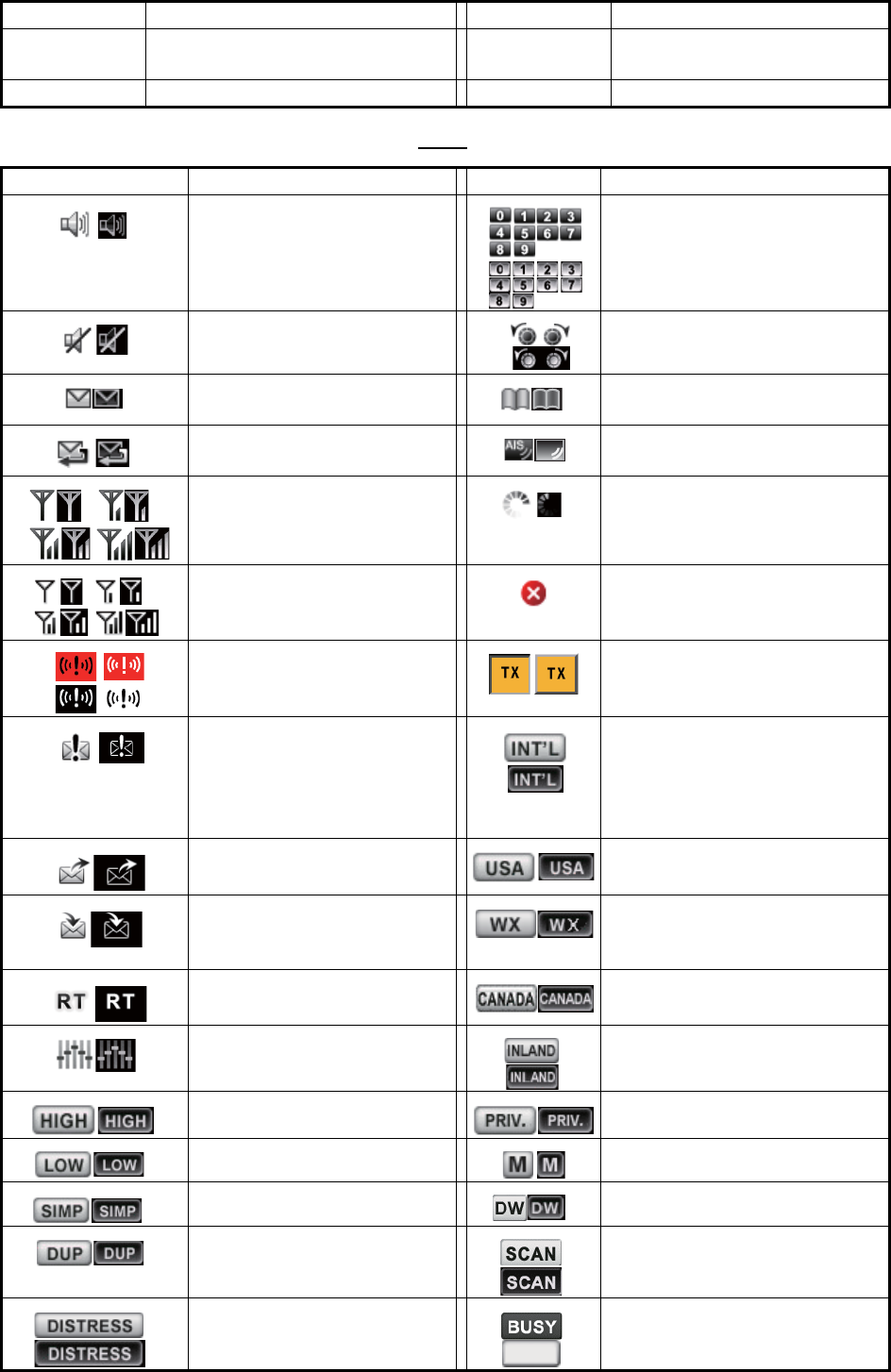
APPENDIX 3 ABBREVIATIONS LIST
AP-14
Icons
UTC Coordinated Universal Time/ Uni-
versal Time, Coordinated
VOL Volume
VDR Voyage Data Recorder WR Watchkeeping Receiver
Icon Meaning Icon Meaning
Speaker ON Number keys
Speaker OFF CHANNEL/ENTER knob
Unread message Name of the ship registered in
address book
Auto ACK for individual mes-
sage is ON.
Name of the ship registered in
AIS target list
Radio field intensity on the
RT screen
Data is being updated regular-
ly.
Radio field intensity on the
screens except the RT
screen
Unsolved error
Send a distress alert of your
ship.
Transmitting
• Receive a distress alert
from a ship in distress.
• Send a distress relay on
behalf of a ship in dis-
tress.
Channel region is INT’L.
Send a general (safety, ur-
gency or routine) message.
Channel region is USA.
Receive a general (safety,
urgency or routine) mes-
sage.
Channel region is WX.
Communicate via radiotele-
phone
Channel region is CANADA.
Equalizer mode is on. Channel region is INLAND-W.
Output power is high. Channel region is PRIVATE.
Output power is low. Channel region is MEMORY.
Simplex frequency Dual watching
Duplex frequency Scanning
Distress frequency Squelch is opened.
Abbreviation Term Abbreviation Term
AIS
BUSY

AP-15
APPENDIX 4 DIGITAL INTERFACE
(IEC 61162-1)
I/O Sentences
Input sentences (IEC 61162-1)
GGA, GLL, ZDA, GNS, RMC, VDM
Input sentence description
• GGA - Global positioning system (GPS) fix data
• GLL - Geographic position - latitude/longitude
• ZDA - Time and date
$**GGA,hhmmss.ss,llll.lll,a,yyyyy.yy,a,x,xx,x.x,x.x,M,x.x,M,x.x,xxxx*hh<CR><LF>
1 2 3 4 5 6 7 8 9 10 11 12 13 14
1. UTC of position (000000.00 - 235959.99)
2. Latitude (0000.0000 - 9000.0000)
3. N/S
4. Longitude (00000.0000 - 18000.0000)
5. E/W
6. GPS quality indicator (1 - 5)
7. Number of satllite in use (no use)
8. Horizontal dilution of precision (no use)
9. Antenna altitude above/below mean sealevel (no use)
10. Unit, m
11. Geoidal separation (no use)
12. Unit, m
13. Age of differential GPS data (no use)
14. Differential reference station ID (no use)
$**GLL,llll.ll,a,yyyyy.yy,a,hhmmss.ss,a,x*hh<CR><LF>
1 2 3 4 5
6 7
1. Latitude (0000.0000 - 9000.0000)
2. N/S
3. Longitude (00000.0000 - 18000.0000)
4. E/W
5. UTC of position (000000.00 - 235959.99)
6. Status (A=data valid V=data invalid)
7. Mode indicator (A=Autonomous D=Differential
N=No fix S=Simulator mode
$**ZDA,hhmmss.ss,xx,xx,xxxx,xx,xx*hh<CR><LF>
1 2 3 4 5 6
1. UTC (000000.00 - 235959.99)
2. Day (01 - 31)
3. Month (01 -12)
4. Year (2000 - 2049)
5. Local zone, hours (no use)
6. Loca zone, minutes (no use)

APPENDIX 4 DIGITAL INTERFACE (IEC 61162-1)
AP-16
• GNS - GNSS fix data
• RMC - Recommended minimum specific GNSS data
• VDM - UAIS VHF data-link message
$**GNS,hhmmss.ss,llll.ll,a,yyyyy.yy,a,c--c,xx,x.x,x.x,x.x,x.x,x.x,a*hh<CR><LF>
1 2
3 4 5 6 7 8 9 10 11 12 13
1. UTC of position (000000.00 - 235959.99)
2. Latitude (0000.0000 - 9000.0000)
3. N/S
4. Longitude (00000.0000 - 18000.0000)
5. E/W
6. Mode indicator
N=No fix A=Autonomous D=Differential P=Precise R=Real Time Kinematic
F=Float RTK S=Simulator Mode
7. Total number of satellites in use (00 - 99)
8. HDOP (no use)
9. Antenna altitude, meters (no use)
10. Geoidal separation (no use)
11. Age of differential data (no use)
12. Differential reference station ID (no use)
13. Navigational status indicator (S=Safe C=Caution U=Unsafe V=Navigational status not valid)
$**RMC,hhmmss.ss,A,llll.ll,a,yyyyy.yy,a,x.x,x.x,ddmmyy,x.x,a,a,a*hh<CR><LF>
1 2 3 4 5 6 7 8 9 10
11 12 13
1. UTC of position fix (000000.00 - 235959.99)
2. Status (A=data valid, V=navigation receiver warning)
3. Latitude (0000.0000 - 9000.0000)
4. N/S
5. Longitude (00000.0000 - 18000.0000)
6. E/W
7. Speed over ground, knots (no use)
8. Course over ground, degrees true (no use)
9. Date (010100 - 311249)
10. Magnetic variation, degrees (no use)
11. E/W
12. Mode indicator (A= Autonomous D= Differential
F=Float RTK N=No fix P=Precise R=Real time kinematic S= Simulator mode
13. Navigational status indicator (S=Safe C=Caution U=Unsafe V=Navigational status not valid)
$**VDM,x,x,x,a,s--s,x,*hh<CR><LF>
1 2 3 4 5 6
1. Total number of sentences needed to transfer the message (1 to 9)
2. Message sentence number (1 to 9)
3. Sequential message identifier (0 to 9, NULL)
4. AIS channel Number (A or B)
5. Encapsulated ITU-R M.1371 radio message (1 - 63 bytes)
6. Number of fill-bits (0 to 5)

APPENDIX 4 DIGITAL INTERFACE (IEC 61162-1)
AP-17
Output sentences (IEC 61162-1)
DSC, DSE, TLL
Output sentence description
• DSC - Digital selective calling information
• DSE - Expanded digital selective calling
• TLL - Target latitude and longitude
$CVDSC,xx,xxxxxxxxxx,xx,xx,xx,x.x,x.x,xxxxxxxxxx,xx,a,a*hh<CR><LF>
1 2 3 4 5 6 7 8 9
10 11
1. Format specifier (2 digits)
2. Address (10 digits)
3. Category (2 digits or NULL)
4. Nature of Distress or first telecommand (2 digits or NULL)
5. Type of Communication or second telecommand (2 digits)
6. Position or Channel /Frequency (Max. 12 digits)
7. Time or Tel. No. (Max. 16 digits)
8. MMSI of ship in distress (10 digits or NULL)
9. Nature of distress (2 digits or NULL)
10. Acknowledgement (R=Acknowledge request B=Acknowledgement S=Neither (end of sequence)
11. Expansion indicator (E or NULL)
$CVDSE,x,x,a,xxxxxxxxxx,xx,c--c,..........,xx,c--c*hh<CR><LF>
1 2 3 4 5 6 7 8 9
1. Total number of sentences (fixed value)
2. Sentence number (fixed value)
3. Query/reply flag (fixed value A=Automatic)
4. Vessel MMSI (10 digits)
5. Data set ‘1’ (code field, fixed value 00)
6. Data set ‘1’ (data field, Enhanced position resolution, Max. 8 characters), NULL
7. Additional data sets
*
, NULL
8. Data set ‘n’ (NULL)
*
9. Data set ‘n’ (NULL)
*
*
: This equipment outputs only “Data set 1”.
$CVTLL,xx,llll.ll,a,yyyyy.yy,a,c--c,hhmmss.ss,a,a*hh<CR><LF>
1 2 3 4 5 6 7 8 9
1. Target number, NULL
2. Latitude (0.0000 - 9000.0000)
3. N/S
4. Longitude (0.0000 - 18000.0000)
5. E/W
6. Target name, NULL
7. UTC of data (000000 - 235959)
8. Target status, NULL
9. Reference target, NULL
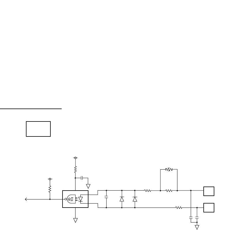
APPENDIX 4 DIGITAL INTERFACE (IEC 61162-1)
AP-18
P - sentences
pireq, pidat, CVdmr, CVdma
P - sentence description
• PFEC,pireq - Equipment information request
When this sentence is input, the equipment outputs the PFEC,pidat sentence.
• PFEC,pidat - Equipment information
• PFEC,CVdmr - Digital selective call Message call Request
• PFEC,CVdma - Digital selective call Message call Acknowledgement
Schematic diagram
$ PFEC, pireq, sentence
$ PFEC, pidat, sentence
$ PFEC, CVdmr, sentence
$ PFEC, CVdma, sentence
+3.3V
GNSS_IN 43
1
5PC400
6
0.1
µ
2.2k
10
100p
1SS272
1SS272
0
100 330
MAIN
05P0843
GNSS_RD-H
GNSS_RD-C
21
22
1000p
10
1000p
[GNSS_SIO] Input only
+3.3V
(Not mount) J1
JUNCTION
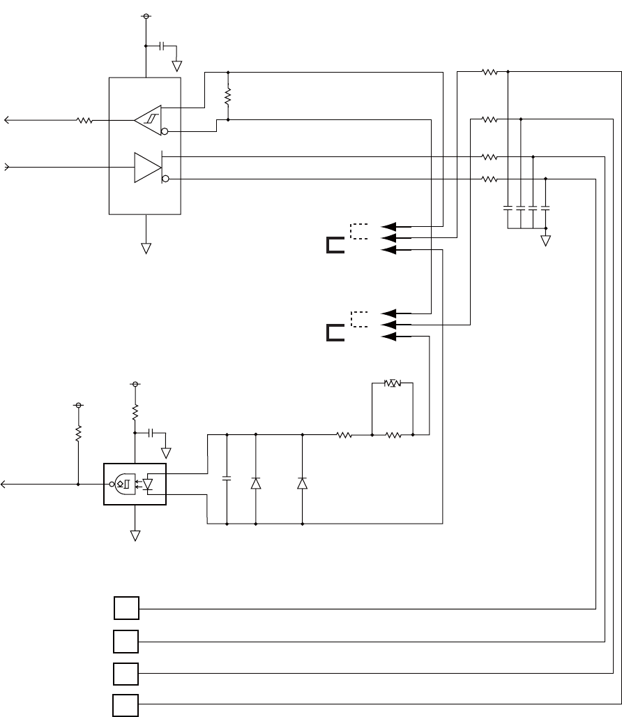
APPENDIX 4 DIGITAL INTERFACE (IEC 61162-1)
AP-19
Load requirements as a listener
Isolation: Optocoupler Input impedance: 430Ω Max. voltage: ±15 V Threshold: 4 mA
+3.3V
4
1
0.1
µ
RS422_RXD
RS422_TXD
22
2 R
3 D
VCCGND
SN65HVD30DR
A 8
B 7
Y 5
Z 6
120
0.5W
J17
Z_149_3P
1
2
3
RS-422
IEC61162-1
(default)
RS-422
J18
Z_149_3P
1
2
3
MULTI_RD-B
MULTI_RD-A
MULTI_TD-B
MULTI_TD-A
5PC400
6
0.1
µ
10
1
3
4
NMEA_RXD
2.2k
100p
1SS272
1SS272
100 330
0
10
10
13
14
10
15
10
16
[MULTI_SIO]
100px4
IEC61162-1
(default)
+3.3V
+3.3V
(Not mount)
(Not mount)
J1 JUNCTION
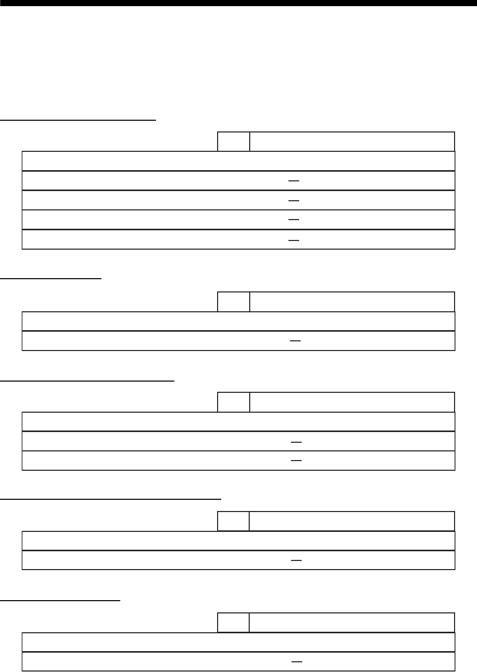
AP-20
APPENDIX 5 PARTS LIST
This equipment contains complex modules in which fault diagnosis and repair down to component
level are not practical (IMO A.694(17)/8.3.1). Only some discrete components are used. FURUNO
Electric Co., Ltd. Believes identifying these components is of no value for shipboard maintenance;
therefore, they are not listed in this manual. Major modules can be located on the parts location
photos on pages AP-21 thru AP-22.
Transceiver Unit FM-8900S
Handset HS-2003
Remote Handset HS-8900(-W)
Remote Handset Hanger HG-8900(-W)
Junction Box IF-8900
Unit
Code No.
ELECTRICAL PARTS LIST Transceiver Unit FM-8900S
05P0882, PANEL
05P0849, PWR
05P0843, MAIN
05P0841, TRX_WR
PRINTED CIRCUIT BOARD
Unit
Code No.
ELECTRICAL PARTS LIST Handset HS-2003
05P0780, HANDSET
PRINTED CIRCUIT BOARD
Unit
Code No.
ELECTRICAL PARTS LIST Remote Handset HS-8900(-W)
05P0781B, HS CONT
05P0715, KEY
PRINTED CIRCUIT BOARD
Unit
Code No.
ELECTRICAL PARTS LIST Remote Handset Hanger HG-8900(-W)
05P0798, TB
PRINTED CIRCUIT BOARD
Unit
Code No.
ELECTRICAL PARTS LIST Junction Box IF-8900
05P0850, JUNCTION
PRINTED CIRCUIT BOARD
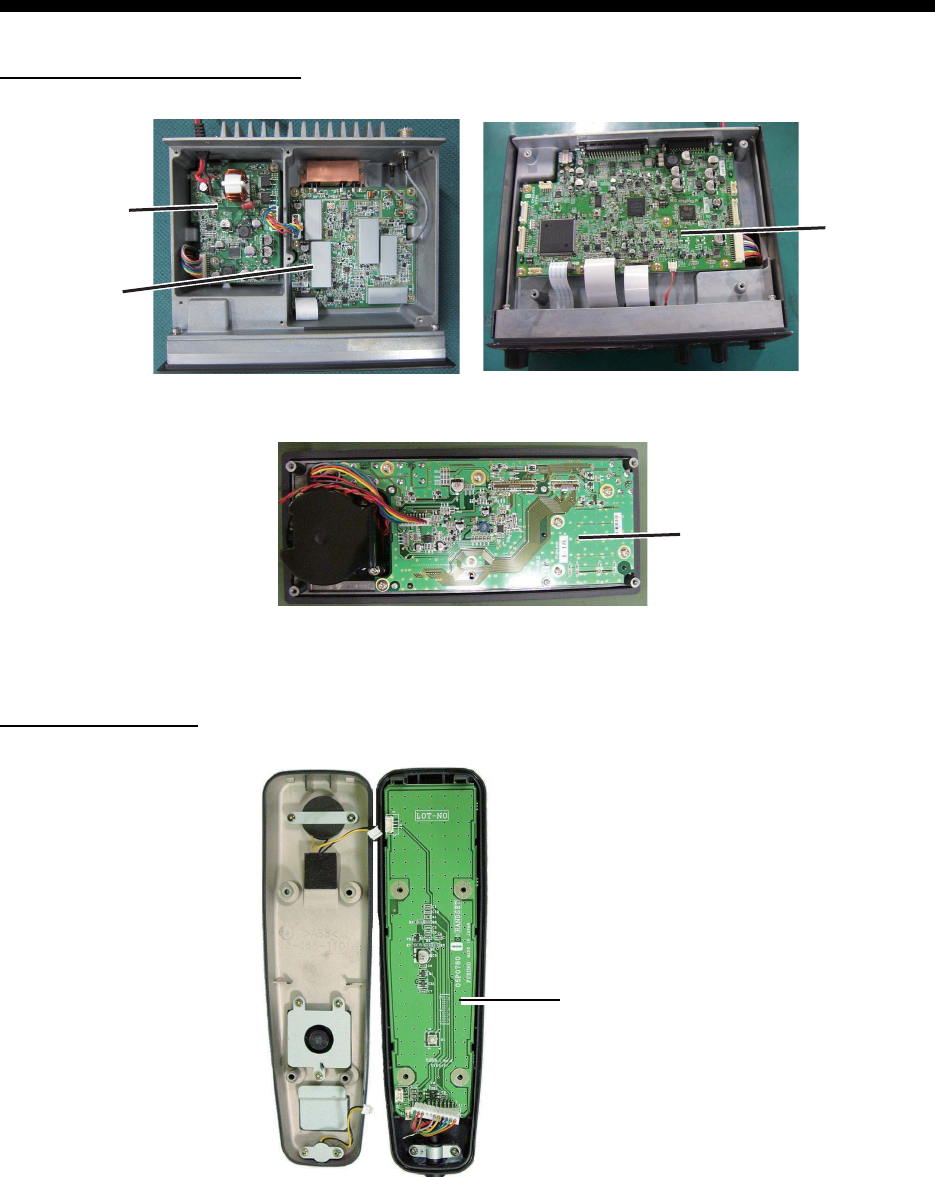
AP-21
APPENDIX 6 PARTS LOCATION
Transceiver unit FM-8900S
Handset HS-2003
05P0882
PANEL
Top cover removed
Back side of front panel
Bottom cover removed
05P0849
PWR
05P0841
TRX_WR
05P0843
MAIN
05P0780
HANDSET
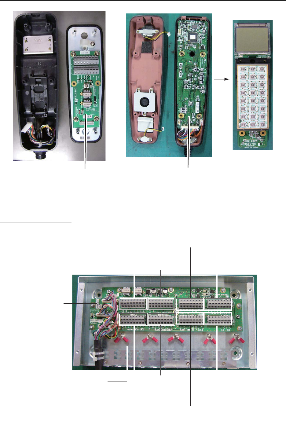
APPENDIX 6 PARTS LOCATION
AP-22
Remote station RB-8900 (HS-8900, HG-8900) / RB-8900-W (HS-8900-W, HG-8900-W)
Junction box IF-8900
05P0798
TB
05P0781B
HS CONT
HG-8900
HG-8900-W
HS-8900
HS-8900-W
(Hanger) (Handset)
(Rear side)
05P0715
KEY
05P0850
JUNCTION
TB1
(REMOTE1)
TB3
(REMOTE3)
TB7
(ALARM SYSTEM/
INS/AIS/PLOTTER)
TB5
(ANALOG WING(LEFT)/VDR)
TB8
(ALARM UNIT)
TB6
(ANALOG WING(RIGHT)/GNSS)
TB4
(REMOTE 4)
TB2
(REMOTE 2)
Lug for connection
of shield of
TTYCSLA cables
FURUNO
FM-8900S
SP - 1 E5680S01E
SPECIFICATIONS OF MARINE VHF RADIOTELEPHONE
FM-8900S
1 GENERAL
1.1 Number of channels INTL: 57
USA: 50
Weather: 10
Canada: 57
INLAND-WA: 57
Private: 20
Memory CH: 50
1.2 Frequency stability Within ±1.5kHz
1.3 Communication system Simplex/Semi-duplex
1.4 Class of emission 16K0G3E (F3E) Voice, 16K0G2B (F2B) DSC
1.5 Antenna impedance 50 ohms
1.6 Display 4.3-inch color dot matrix LCD, 480 x 272 dots
1.7 Visible distance 0.7 m nominal
2 TRANSMITTER
2.1 Frequency range 155.000 to 161.475 MHz
2.2 Output power 25W max., 1W at power reduction
2.3 Frequency deviation Within ±5 kHz
3 RECEIVER
3.1 Frequency range Simplex: 155.000 to 161.475 MHz
Semi-duplex: 159.600 to 164.200 MHz
3.2 Receiving system Double superheterodyne
3.3 Intermediate frequency 1st: 51.1375 MHz, 2nd: 62.5 kHz
3.4 Sensitivity +6 dBμV or less (20 dB SINAD)
3.5 Channel selectivity 70 dB or more
3.6 Spurious response 70 dB or more
3.7 AF output Built-In speaker: 3W (4 ohms, THD: within 10%),
Handset earpiece: 2mW (150 ohms)
4 DSC
4.1 Protocol Rec. ITU-R M.541-9, M.493-13 (class A), M.689-2
4.2 Baud rate 1200 baud ±30 ppm max.
4.3 Modulation AFSK
4.4 Frequency of modulation 1700 ±400 Hz, Mark: 1300 Hz, Space: 2100 Hz
5 CH70 WATCH KEEPING RECEIVER
5.1 Receiving frequency 156.525 MHz
5.2 Receiving system Double superheterodyne
FURUNO
FM-8900S
SP - 2 E5680S01E
5.3 Intermediate frequency 1st: 38.3625 MHz, 2nd: 37.5 kHz
5.4 Sensitivity 0 dBμV or less (SER<1%)
5.5 Channel selectivity 70 dB or more
5.6 Spurious response 70 dB or more
6 INTERFACE
6.1 Navigation data IEC61162-1 Ed.4(2010-11)
Input sentences GGA, GLL, GNS, RMC, VDM, ZDA
Output sentences DSC, DSE, TLL
7 POWER SUPPLY
7.1 Power voltage 24 VDC (-10%, +30%)
7.2 Power consumption (with all options)
Transmit 4.7A max. at 25W output
Receive 2.3A max. at 4W audio output
Waiting 1.3A max.
8 ENVIRONMENTAL CONDITION
8.1 Ambient temperature -15°C to +55°C
8.2 Relative humidity 93% or less at +40°C
8.3 Degree of protection
Transceiver unit (FM-8900S) IP20 (IP22: option)
Handset/Hanger (HS-2003/FP05-05510) IP24
Remote station RB-8900: IP22, RB-8900-W: IP56
Junction box IP20, IP22 (bulkhead mount, option)
8.4 Vibration IEC 60945 Ed.4
9 COATING COLOR
9.1 Transceiver unit N2.5 (fixed)
9.2 Remote station/ handset N2.5 (fixed)
9.3 VHF console 7.5BG7/2, 2.5G7/2 or specified

IN-1
INDEX
A
Abbreviation ..........................................AP-13
Address book
deleting...................................................5-11
editing.....................................................5-10
list.............................................................5-8
registration ...............................................5-9
Alarm lists ................................................5-21
All ships message
receiving.................................................4-12
sending...................................................4-11
Audio alarms ..............................................2-2
Auto ACK setting......................................5-19
B
Brilliance
remote handset ........................................6-3
transceiver unit.........................................1-3
C
Channel region...........................................5-2
remote handset ........................................6-3
transceiver unit.........................................1-3
Channel selection
remote handset ........................................6-4
transceiver unit.........................................1-4
Contrast (remote handset) .........................6-3
Control description
remote handset ........................................6-1
transceiver unit.........................................1-1
D
Daily test ....................................................7-1
Date and time setting .................................5-5
Digital interface .....................................AP-15
Distress alert
canceling ................................................3-13
receiving...................................................3-4
sending.....................................................3-1
Distress relay
receiving.................................................3-13
sending...................................................3-10
DSC messages ..........................................2-1
Dual channels (DW) ...................................1-5
E
Error message ...........................................7-3
External alarm setting ................................5-7
G
Group message
receiving...................................................4-7
sending.....................................................4-6
Group message preparation ....................5-14
I
Icon .......................................................AP-14
Individual message
receiving...................................................4-4
sending.....................................................4-1
Individual message preparation ...............5-13
Intercom ............................................. 1-8, 6-5
L
Log file
deleting...................................................5-18
opening ..................................................5-17
M
Maintenance ..............................................7-2
Medical message
receiving.................................................4-19
sending...................................................4-18
Memory channel calling up
remote handset ........................................6-4
transceiver unit.........................................5-2
Memory configuration.................................5-3
MENU screen open/close ..........................5-1
Menu tree ................................................AP-1
N
Neutral message
receiving.................................................4-17
sending...................................................4-16
P
Parst list ................................................AP-20
Parst location ........................................AP-21
Polling request message..........................4-15
Position message
receiving.................................................4-15
sending...................................................4-13
Position setting...........................................5-4
Power on/off
remote handset ........................................6-2
transceiver unit.........................................1-2
Printing message .......................................5-4
Priority ........................................................1-7
Propose channel ......................................5-20
PSTN message
receiving.................................................4-10
sending.....................................................4-8
PSTN message preparation.....................5-15
R
Replay function ........................................1-12
RT application setting.................................5-8
RT screen
remote handset ........................................6-2
transceiver unit.........................................1-2
S
Scanning channels.....................................1-6
Session ......................................................1-9
INDEX
IN-2
Sound setting
remote handset ....................................... 6-6
transceiver unit ...................................... 5-20
Speaker
remote handset ....................................... 6-5
transceiver unit ........................................ 1-5
Special message..................................... 5-20
T
Test call..................................................... 7-4
Test message preparation ...................... 5-15
Timeout setting.......................................... 5-5
Transmission
remote handset ....................................... 6-4
transceiver unit ........................................ 1-4
Troubleshooting ........................................ 7-2
V
VHF channel lists ....................................AP-3
