Furuno Inmarsat C Mobile Earth Station Felcom 12 Users Manual
FELCOM 12 to the manual 4202c3e6-da70-4f43-b9fa-fb976489d4ad
2015-02-02
: Furuno Furuno-Inmarsat-C-Mobile-Earth-Station-Felcom-12-Users-Manual-428685 furuno-inmarsat-c-mobile-earth-station-felcom-12-users-manual-428685 furuno pdf
Open the PDF directly: View PDF ![]() .
.
Page Count: 182 [warning: Documents this large are best viewed by clicking the View PDF Link!]

INMARSAT-C
MOBILE EARTH STATION
MODEL FELCOM 12
C
9-52, Ashihara-cho,
Nishinomiya, Japan
Telephone: 0798-65-2111
Telefax: 0798-65-4200
Your Local Agent/Dealer
All rights reserved.
PUB. No. OME-56130
FELCOM 12
(YOSH)
FIRST EDITION : NOV. 1997
M2 : JAN. 22, 2003
Printed in Japan
iiiiiiiiiiiii i
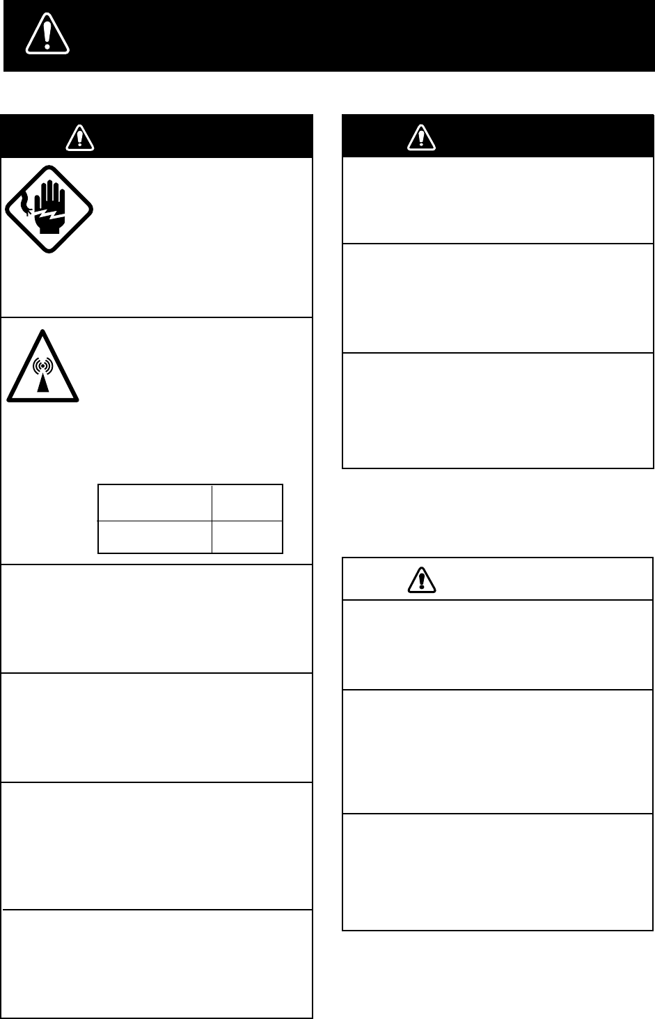
SAFETY INSTRUCTIONS
Use the proper fuse.
Use of a wrong fuse can result in fire or
permanent equipment damage.
Do not use the equipment for other than
its intended purpose.
Personal injury can result if the equipment
is used as a chair or stepping stool, for
example.
Do not place objects on the top of the
equipment.
The equipment can overheat or personal
injury can result if the object falls.
CAUTIONCAUTION
Do not operate the equipment with wet
hands.
Electrical shock can result.
Keep heater away from equipment.
Heat can alter equipment shape and melt
the power cord, which can cause fire or
electrical shock.
Any repair work must be done by a
licensed radio technician.
Improper repair work can cause electrical
shock or fire.
WARNING
WARNING
Leave the equipment powered while
underway.
Distress cannot be communicated unless
the equipment is powered.
Do not disassemble or modify the
equipment.
Fire, electrical shock or serious injury can
result.
Turn off the power immediately if water
leaks into the equipment or the equip-
ment is emitting smoke or fire.
Continued use of the equipment can cause
fire or electrical shock.
Do not place liquid-filled containers on
the top of the equipment.
Fire or electrical shock can result if a liquid
spills into the equipment.
Do not open the equipment.
Hazardous voltage which can
cause electrical shock, burn
or serious injury exists inside
the equipment. Only qualified
personnel should work inside
the equipment.
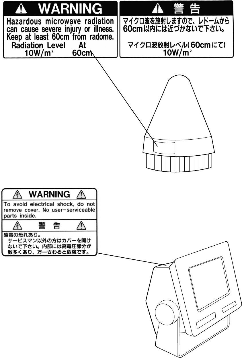
Hazardous microwave.
Do not approach within
60 cm of the antenna radome
when it is transmitting.
Microwave radiation can be
harmful to the human body,
particularey the eyes.
WARNING
WARNING
Radiation Level At
10W/m 60 cm
2
ii
WARNING Label attached
Name: Warning Label
Type: 16-013-2013-1
Code No.: 100-251-640
Antenna Unit
Terminal Unit
Name: Warning Label(1)
Type: 16-003-1011-0
Code No.: 100-236-230

iii
CONTENTS
MENU TREE .....................................................................................vii
OPERATIONAL OVERVIEW ........................................................... viii
PROGRAM NUMBER ........................................................................ ix
FOREWORD .......................................................................................1
Introduction .............................................................................................................................. 1
Features..................................................................................................................................... 2
About This Manual ................................................................................................................... 3
FELCOM 12 System Configuration......................................................................................... 4
INMARSAT-C SYSTEM ......................................................................5
Introduction .............................................................................................................................. 5
Inmarsat System Configuration ................................................................................................ 6
Communications Network ........................................................................................................ 9
Types of MES ...................................................................................................................... 10
Peripheral Equipment ............................................................................................................. 11
Distress/Urgent Receiving Call Unit (IC-303) .................................................................... 11
Distress Alert Unit (IC-302) ................................................................................................ 11
Distress Message Controller (DMC-5: Option)................................................................... 11
OPERATIONAL OVERVIEW ...........................................................1-1
The Communication Unit ......................................................................................................1-1
Self test ...............................................................................................................................1-1
When the audible alarm sounds..........................................................................................1-1
The Terminal Unit..................................................................................................................1-2
Floppy disk drive ................................................................................................................1-2
Floppy disk .........................................................................................................................1-2
Printer PP-510 (optional supply) ...........................................................................................1-3
Keyboard ...............................................................................................................................1-4
Key description...................................................................................................................1-4
Shortcut key operation........................................................................................................1-6
Function Menus .....................................................................................................................1-6
Selecting menu, menu options............................................................................................1-7
Function menu description .................................................................................................1-7
Sample menu operation ......................................................................................................1-8
Display Indications ................................................................................................................1-9
Error Messages and Alerts ...................................................................................................1-11
Silencing the Audible Alarm................................................................................................1-12
Silencing the alarm by the Setup menu ............................................................................1-12
Using a Personal Computer as a Terminal Unit...................................................................1-13
PC requirements ...............................................................................................................1-13
Installing the program.......................................................................................................1-13
Contents of program disk .................................................................................................1-14
iv
SYSTEM INITIALIZATION ...............................................................2-1
System Settings......................................................................................................................2-1
Two sets of DTEs installed.................................................................................................2-1
System setup.......................................................................................................................2-2
Terminal Setup.......................................................................................................................2-6
Login and Logout ..................................................................................................................2-7
Login ..................................................................................................................................2-8
Logout ................................................................................................................................2-9
EGC Settings .......................................................................................................................2-11
What is the EGC (Enhanced Group Call) service?...........................................................2-11
EGC setup.........................................................................................................................2-12
Programming EGC channels ............................................................................................2-15
Programming NCS Channels...............................................................................................2-16
LES List Operations ............................................................................................................2-18
Programming the LES list ................................................................................................2-18
Deleting and changing the LES list ..................................................................................2-20
Printing the LES list .........................................................................................................2-20
Station List Operations ........................................................................................................2-22
Programming the station list.............................................................................................2-22
Editing the station list.......................................................................................................2-25
Printing the station list......................................................................................................2-25
Entering Own Ship’s Position..............................................................................................2-26
Setting Directories ...............................................................................................................2-27
E-mail Service List ..............................................................................................................2-28
E-mail Setup ........................................................................................................................2-30
FILE OPERATIONS .........................................................................3-1
Preparing a Message ..............................................................................................................3-1
Preparing a routine message ...............................................................................................3-1
Preparing a confidential message .......................................................................................3-2
Editor menu setup...............................................................................................................3-3
Cutting and pasting text......................................................................................................3-4
Copying and pasting text ....................................................................................................3-5
Insert (with Citation) ..........................................................................................................3-6
Select All ............................................................................................................................3-6
Search and Replace.............................................................................................................3-6
Go to line ............................................................................................................................3-6
Time or Pos. ins ..................................................................................................................3-6
Saving a Message ..................................................................................................................3-7
Formatting a floppy disk ....................................................................................................3-7
Saving a message................................................................................................................3-8
Opening a File .....................................................................................................................3-10
Opening a file ...................................................................................................................3-10
Switching between files....................................................................................................3-11
Opening a file where a working area is occupied.............................................................3-11
Saving a File Under a New Name .......................................................................................3-12
Printing a File ......................................................................................................................3-13
Combining Files ..................................................................................................................3-14
Deleting a File .....................................................................................................................3-14
MIME (Multipurpose Internet Mail Extensions).................................................................3-15
Rename ................................................................................................................................3-16
v
INMARSAT-C COMMUNICATIONS .................................................4-1
Transmitting...........................................................................................................................4-1
Code description.................................................................................................................4-1
Transmitting prepared message ..........................................................................................4-2
Transmitting message stored on floppy disk (multiple address) ........................................4-9
Canceling transmission.....................................................................................................4-13
Confirming delivery status (message status list) ..............................................................4-14
Manually requesting delivery status .................................................................................4-16
The 2-digit code services..................................................................................................4-17
Inserting the destinations of a fax terminal ......................................................................4-19
Receiving .............................................................................................................................4-20
When a message is received .............................................................................................4-20
Setting the receive alarm ..................................................................................................4-21
Displaying receive messages ............................................................................................4-22
Printing receive messages.................................................................................................4-23
Saving receive messages to a floppy disk ........................................................................4-24
Automatically saving receive messages ...........................................................................4-24
Deleting receive messages................................................................................................4-25
Distress/Urgent Receiving Call Unit IC-303....................................................................4-26
Display Log .........................................................................................................................4-26
Displaying and printing the display log............................................................................4-26
Automatic printing of display log.....................................................................................4-27
Display send message log or receive message log ...........................................................4-28
EGC Messages.....................................................................................................................4-28
Displaying and reprinting EGC messages ........................................................................4-28
Displaying EGC closed network ID (ENID)....................................................................4-29
Receiving EGC distress or urgent message ......................................................................4-30
Tx Message Example Printout.............................................................................................4-30
DATA REPORTING AND POLLING ................................................5-1
Data Reporting.......................................................................................................................5-1
Setting a data report............................................................................................................5-1
Setting a message report.....................................................................................................5-4
Polling....................................................................................................................................5-6
Polling command................................................................................................................5-6
Other polling command......................................................................................................5-7
Polling reception.................................................................................................................5-8
DNID (Data Network Identification).....................................................................................5-9
Displaying DNID................................................................................................................5-9
Enabling/Disabling DNID ................................................................................................5-10
DISTRESS ALERT...........................................................................6-1
Preparing a Distress Alert ......................................................................................................6-1
Transmitting a Distress Alert .................................................................................................6-3
Testing Distress Button..........................................................................................................6-4
Distress Communications ......................................................................................................6-5
vi
OTHER FUNCTIONS .......................................................................7-1
Aborting an Operation ...........................................................................................................7-1
Scanning NCS........................................................................................................................7-2
Selecting EGC Receiving Channel ........................................................................................7-3
Selecting NCS Channel .........................................................................................................7-4
MAINTENANCE ...............................................................................8-1
Safety Information .................................................................................................................8-1
General Checking and Maintenance ......................................................................................8-2
Cleaning the terminal unit and communication unit ..........................................................8-2
Checking connectors and earth terminal ............................................................................8-2
Floppy disk drive head .......................................................................................................8-2
When the power can’t be turned on (power lamp does not light) ......................................8-2
Self Tests................................................................................................................................8-3
Self test at power application (communication unit)..........................................................8-3
Testing the communication unit through the keyboard ......................................................8-3
Performance Verification (PV) Test.......................................................................................8-4
PV test sequence.................................................................................................................8-4
PV test procedure ...............................................................................................................8-5
Results of PV test ...............................................................................................................8-6
System Status Monitor...........................................................................................................8-7
Interpreting the system status monitor ...............................................................................8-8
Replacing Internal Battery.....................................................................................................8-9
Error Messages ....................................................................................................................8-10
SPECIFICATIONS.........................................................................SP-1
APPENDIX ....................................................................................AP-1
International Telex/Telephone Country Code List............................................................. AP-1
International Telex Abbreviations...................................................................................... AP-9
Glossary of Acronyms ..................................................................................................... AP-10
International Telegraphy Alphabet....................................................................................AP-11
Error Messages and Alerts ............................................................................................... AP-12
LES IDs List .................................................................................................................... AP-15
Digital Interface (IEC 61162-2)....................................................................................... AP-16
INDEX ............................................................................................ IN-1
Declaration of conformity to type

vii
MENU TREE
Numerals in parenthesis are page numbers.
F1: File
F7: Options
1: Login
2: Logout
3: Abort
4: Select NCS
5: Ocean Region
6: Test
F6: Logs
1: Send Message Log
2: Receive Message Log
3: EGC Log
4: Log
F2: Edit
1: Cut DEL
2: Copy ALT-C
3: Paste INS
4: Insert (with Citation)
5: Select All ALT-A
6: Search or Replace
7: Go to line
8: Time or Pos. Ins
9: Change Window ALT-V
F8: Setup
1: Distress Alert Setup
2: System Setup
3: Editor Setup
4: Terminal Setup
5: EGC Setup
6: Auto Mode Setup
7: E-Mail Setup
8: Directories
9: Configuration
F3: Transmit
1: Transmit Message
2: Cancel
3: Request Delivery Status
F5: Reports
1: Data Report
2: Message Report
3: Date Network ID
F4: EGC
1: Display EGC Message
2: EGC Network ID
F9: Position
F10: Stop Alarm
(3-1)
(3-10)
(3-9)
(3-12)
(3-14)
(3-16)
(3-13)
(3-7)(IB-581only)
(3-15)
(2-7)
(2-9)
(7-1)
(7-4)
(7-2)
(6-4, 8-3)
(6-1)
(2-2)
(3-3)
(2-1)
(2-11)
(4-21, 4-24, 4-27)
(2-30)
(2-27)
(3-4)
(3-5)
(3-5)
(3-6)
(3-6)
(3-6)
(3-6)
(3-6)
(3-6)
(3-6)
(3-11)
(4-2, 4-9)
(4-13)
(4-14)
(5-1)
(5-4)
(5-8)
(4-28)
(4-22)
(4-28)
(4-26)
(2-26)
(4-28)
(4-29)
1: Station List
2: LES List
3: EGC Channel List
4: NCS Channel List
5: E-Mail Service List
(2-22, 2-25)
(2-20, 2-18)
(2-15, 7-3)
(2-16)
(2-28)
(1-1)
1: Top of Text Fn-←
2: End of Text Fn-→
3: Go to Line
1: New ALT-N
2: Open ALT-O
3: Close ALT-Q
4: Save ALT-S
5: Delete ALT-D
6: Rename
7: Print ALT-P
8: Format Disk
9: MIME (Decode)
9: QUIT (PC only)
viii
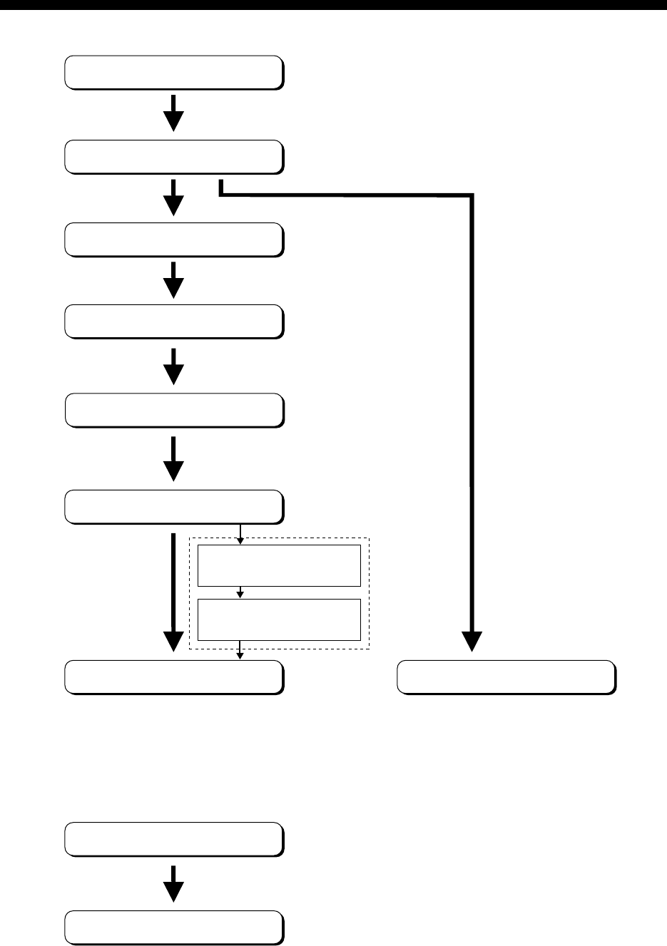
OPERATIONAL OVERVIEW
Power On
Login
System Initialization
Program LES
Program Station
Prepare Message
Transmitting
Logout
Power Off
Receiving
Saving a message
(page 3-8)
Retrieving a message
(page 3-10)
The FELCOM 12 should be turned on for the duration of a voyage.
Be sure to logout with Inmarsat-C system before turning off the equipment.

ix
PROGRAM NUMBER
rofnosaeR.oNbuP etaD,noitacifidoM .oNmargorPerawtfoS
K-03165-EMO
CEIhtiwmrofnocotdeifidoM 2noitidE1-26116
4/2002
)3/8991(300-2110-5611UPC )3/8991(300-4110-561DOMED )4/2002(410-8110-5612UPC )4/0002(600-6110-561LANIMRET
This page is intentionally left blank.

1
FOREWORD
Introduction
FURUNO Electric Company thanks you for considering and purchas-
ing the FELCOM 12 Inmarsat-C Mobile Earth Station. We are confi-
dent you will discover why the FURUNO name has become synony-
mous with quality and reliability.
Mainly consisting of an antenna unit, a communication unit and ter-
minal unit, the FELCOM 12 provides the full range of distress and
general communication services for mobile and fixed terrestrial sub-
scribers in the Inmarsat-C communication network. Its compact size
permits installation where space is limited.
FURUNO designs and manufactures this equipment with much at-
tention to operation and maintenance simplicity. However, please read
and follow the recommended procedures for operation and mainte-
nance to get the most out of the equipment.
This manual provides a brief introduction to the Inmarsat-C system
(pages 5 thru 10). For more detailed information, however, please
refer to “Inmarsat-C Maritime User’s Manual” published by Inmarsat.
(It is free of charge.) Below are contact points for Inmarsat.
Inmarsat-C Maritime Customer Relations Officer
Maritime Services Operations Department
International Maritime Satellite Organization (Inmarsat)
Address: 99 City Road, London EC1Y 1AX, UK
Telephone: +44 71 728 1000 (Switchboard)
Fax: +44 71 728 1192
Telex: 297201 Inmarsat G
2
Features
¡Conforms to the following standards: IMO A.807(19),
MSC. 68(68), Annex 4, IMO A.694(17), IEC 61097-4 (1994),
IEC 60945 (1996), IEC 61162-1 (2000)
¡E-mail facility
To transmit E-mail, register with the LES provider. E-mail
charges are calculated separately.
¡Built in Enhanced Group Call (EGC) receiver permits operation as
EGC-only receiver.
¡Communication unit accepts a wide variety of peripheral equip-
ment, Distress Message Controller (DMC), personal computer and
remote panel.
¡Connection of 2nd Data Terminating Equipment (DTE) for opera-
tion from remote location such as the bridge
¡Store-and-forward telex communication (public telex network)
¡Data reporting and Polling
¡Internal GPS receiver (option) in the communication unit provides
GPS-generated position.
¡Self test programs for maintenance
¡Terminal unit provides floppy disk drive for unlimited storage of
received and transmitted messages on floppy disks.
¡Menu driven operation
3
About This Manual
A word about the organization of this manual: It is laid out in a user-
friendly manner as possible. We realize a machine like this with its
many, many functions can be a little intimidating to even the experi-
enced MES operator. This is why we have arranged this manual in a
series of sections that start at a basic level and proceed forward in
complexity in a logical manner.
The best way to acquaint yourself with the many facilities this equip-
ment has to offer is to turn it on and try keying in the examples pro-
vided in each of the sections. In hardly no time at all you’ll be enjoying
the benefits of the Inmarsat-C system.
Inmarsat-C System This chapter explains the Inmarsat-C sys-
tem.
Operational Overview This chapter introduces basic operations.
System Initialization Read this chapter to learn how to initialize
the FELCOM 12.
File Operations You will learn how to use the text editor in
this chapter, to prepare, edit and save mes-
sages.
Inmarsat-C Read this chapter to learn how to transmit
Communications and receive in the Inmarsat-C system.
Data Reporting and Polling
This chapter explains data reporting set-
ting and polling reception.
Distress Alert This chapter tells you how to prepare and
transmit the distress alert, and conduct dis-
tress communications.
Other Functions This chapter describes how to abort op-
eration, scan NCS, and select various chan-
nels.
Maintenance The maintenance chapter presents infor-
mation for keeping the FELCOM 12 in top
operating condition.
Appendix The Appendix presents international telex
country codes, international telex abbre-
viations, glossary of acronyms, error mes-
sages and alerts, and international telegra-
phy alphabet.

4
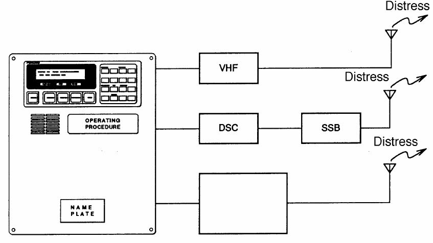
DISTRESS / URGENT
RECEIVING UNIT
ALARM RESET
POWER
FURUNO INMARSAT- C MOBILE EARTH STATION
Antenna Unit
Communication Unit
Terminal Unit
DISTRESS
TYPE IC-302
SEL NO.
COMPASS SAFE DISTANCE
STD M
FURUNO ELECTRIC CO., LTD
DISTRESS
TYPE IC-302
SEL NO.
COMPASS SAFE DISTANCE
STD M
FURUNO ELECTRIC CO., LTD
Distress Alert Unit
IC-302
Distress Alert Unit
IC-302
Distress/Urgent
Receiving Unit
IC-303
FELCOM 12 System Configuration
Figure 1 FELCOM 12 system configuration

5
INMARSAT-C SYSTEM
This chapter provides an overview of the Inmarsat-C satellite com-
munication system.
Introduction
The Inmarsat-C system provides worldwide telex and data transmis-
sion and reception of written information to owners of an Inmarsat-C
transceiver or a terrestrial telex network via satellite.
Communication mode is store-and-forward telex, which means all
information sent are first stored at a LES and then delivered to desig-
nated party.
An EGC (Enhanced Group Call) receiver is built in the FELCOM 12
to receive the following types of messages, broadcast from a LES:
¡SafetyNETTM-governments and maritime authorities can use this
service to distribute maritime safety information to ships within
selected areas.
¡FleetNETTM-commercial subscription organizations or shipping
companies can use this service to transmit trade information (for
example, company news or market prices) simultaneously to a se-
lected group of ships, to provide up-to-the-minute information.
FELCOM 12 allows you to make distress calls which are given im-
mediate priority over all other calls, and are automatically routed to a
land-based Rescue Co-ordination Centre (RCC).
Besides its primary application of ship-shore, shore-ship or ship-ship
communications, the Inmarsat-C service has also proved beneficial
to trucking firms who have found it indispensable for communicat-
ing with their vehicles. In this manual, however, we will concentrate
on ship applications, the main application.
6
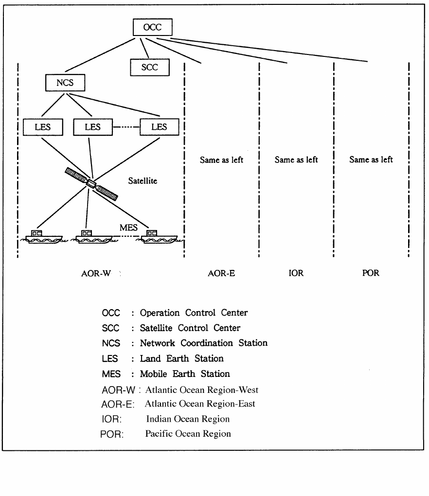
Inmarsat System Configuration
Figure 2 Inmarsat-C satellite communication system

7
The Inmarsat-C system consists of the Operation Control Center
(OCC), Satellite Control Centers (SCC), Network Coordination Sta-
tions (NCS), Land Earth Stations (LES) and Mobile Earth Stations
(MES). The OCC, located at Inmarsat’s London headquarters, coor-
dinates a wide range of activities in the Inmarsat system, including
commissioning of mobile earth stations.
The Inmarsat-C system divides the world into four regions and each
region is covered by its own satellite.
Table 1 Inmarsat system satellites
Region Satellite Satellite Position
AOR-West Inmarsat-2, F4 54.0°W
AOR-East Inmarsat-2, F2 15.5°W
IOR Inmarsat-2, F1 64.5°E
POR Inmarsat-2, F3 178.0°E
In each region there is one NCS and several LESs. The NCS keeps
track of all Inmarsat-C transceivers in its region and broadcasts in-
formation such as navigational warnings, weather reports and news.
The LES provides the link between the MES and the terrestrial tele-
communications networks via satellite.
8
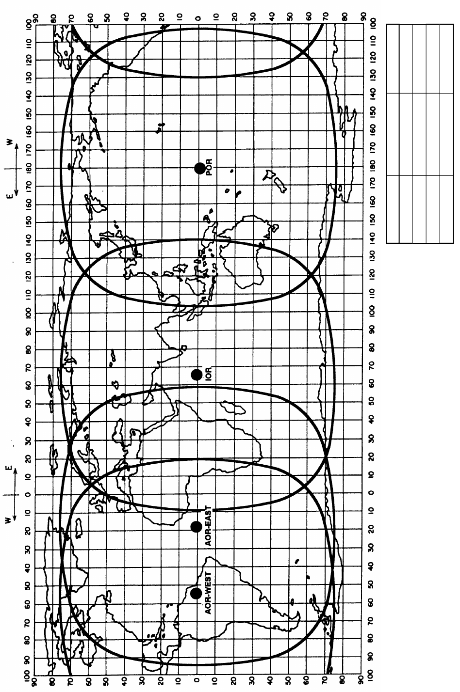
Figure 3 Coverage area of satellites
AREA
SATELLITE NAME
POSITION
POR
INMARSAT-2, F3
178° E
IOR
INMARSAT-2, F1
64.5° E
AOR-EAST
INMARSAT-2, F2
15.5° W
AOR-WEST
INMARSAT-2, F4
54.0° W
9
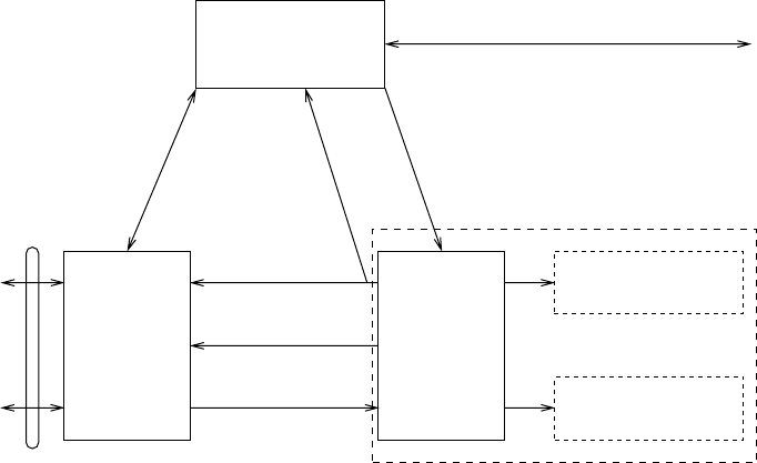
Communications Network
Figure 4 shows the Inmarsat-C communications network.
Network
Coordination
Station (NCS)
NCS/NCS Signaling Link
NCS Common Channel
Mobile Earth
Station (MES)
Data Terminal
Equipment (DTE)
Enhanced Group
Calling (EGC) Receiver
Data Circuit
Terminating
Equipment
(DCE)
MES Signaling
Channel
MES Message
Channel
LES TDM
Channel
Land Earth
Station
(LES)
NCS/LES
Signaling Link
Terrestrial
Communications
Network
Data
Communications
Network
Telex Network
Figure 4 Inmarsat-C communications network
NCS common channel The NCS has two major functions:
1) Transmitting information on a com-
mon channel.
2) Transmitting EGC messages to MESs.
NCS/LES signalling link This is the link between NCS and all
LESs in its region. All EGC messages
pass through this link.
LES TDM channel This channel carries the circuit control
signal for MES and transmits messages
from LES to MES.
MES message channel This channel carries messages from
MES to LES.
MES signaling channel This channel transmits requests, distress
alerts, data reports, etc. In addition, it
carries login and logout from MES to
NCS.
NCS/NCS signaling link This is the link between NCSs. It ex-
changes data between MESs operating
in different ocean regions.
10
MES interface The MES consists of the Data Circuit
Terminating Equipment (DCE) and the
Data Terminal Equipment (DTE). The
DCE consists of the antenna unit and
the communication unit. And the DTE
consists of the terminal unit (or a PC),
keyboard and printer.
Terrestrial network The major functions of the LESs are:
interface
1) Telex store-and-forward conversion
2) Handling EGC messages
3) Handling distress alerts
4) Data Reporting and Polling
Types of MES
There are three types of MES: class 1, class 2 and class 3. The
FELCOM 12 is a class 2 MES.
Class 1 1) Transmits messages to LES
2) Receives messages from LES
Class 2 1) The functions of class 1 plus opera-
tion as an EGC receiver when not
transmitting or receiving.
2) EGC-only receiver
Class 3 The function of class 1 plus simulta-
neous operation as a EGC-only receiver.
11
Peripheral Equipment
The following equipment can be additionally connected to the
FELCOM 12.
Distress/Urgent Receiving Unit (IC-303)
The IC-303 releases an audible alarm and blinks the lamp when dis-
tress message is received. (Refer to page 4-26 for further details.)
When an EGC distress or urgent message is received, with an aural
alarm and blinking lamp.
Distress Alert Unit (IC-302)
The IC-302 enables transmission of the distress alert from a remote
location; for example, ship’s bridge. (Refer to page 6-3 for more de-
tails.)
Distress Message Controller (DMC-5:Option)
The DMC provides for transmission and monitoring of the distress
alert. For further details, refer to the operator’s manual of the DMC-
5.
Inmarsat C
Distress Message Controller DMC-5
Figure 5 Distress Message Controller system
This page is intentionally left blank.

1-1
OPERATIONAL OVERVIEW
This chapter provides an overview of the FELCOM 12 system.
The Communication Unit
The communication unit is the heart of the FELCOM 12 system, trans-
mitting and receiving messages and alerting you to equipment fault.
On its front panel you should see the POWER switch and POWER
lamp. Normally, the power is left on while underway.
POWER
FURUNO INMARSAT- C MOBILE EARTH STATION
NAME PLATE
POWER
Switch
POWER
lamp
Figure 1-1 Communication unit IC-212
Self test
When the communication unit is turned on it conducts a series of
self-tests to check itself for proper operation.
When the audible alarm sounds
The audible alarm sounds in the following circumstances:
1) EGC distress or urgent message is received. (To silence the alarm,
press [ESC] followed by [F10].)
2) During the interval between the transmission of the distress alert
(by own vessel) and the receiving of the distress acknowledge sig-
nal from LES. (The alarm automatically stops when your ship
recives the distress acknowledge signal.)
3) The system status monitor detects equipment fault. (To silence the
alarm, press any key.)
The audible alarm sounds and the terminal unit displays which alarm
is sounding.
1-2
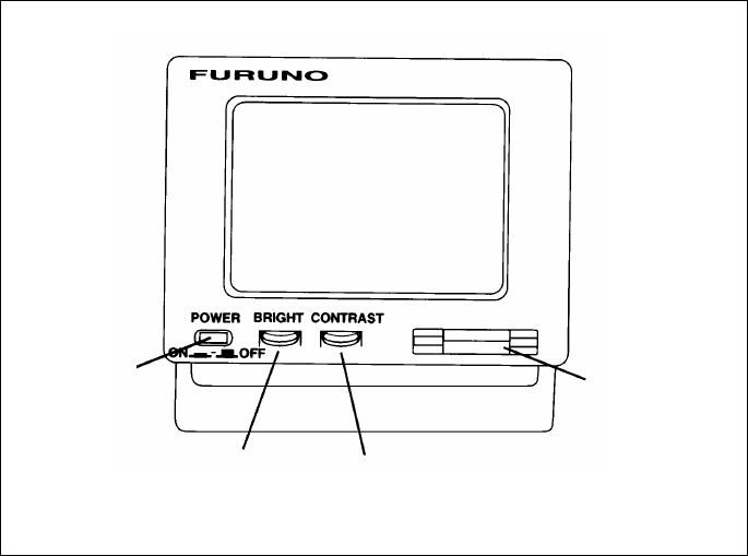
The Terminal Unit
The DTE may consist of IB-581 or IBM compatible pc. All opera-
tions are carried out from the terminal unit, through an easy-to-un-
derstand menu system. For personal computer connection a system
disk (supplied) is required to boot up the computer. Opetarion by a
computer is the same as with the terminal unit except when turning
on the power.
Power switch Floppy disk drive
BRIGHT
control CONTRAST
control
Figure 1-2 Terminal unit IB-581
To turn on/off the unit, press the POWER switch.
Controls for adjustment of screen brilliance and contrast are to the
right of the POWER switch.
Floppy disk drive
The terminal unit provides a floppy disk drive for storing transmitted
and received messages on floppy disks.
Floppy disk
The floppy disk used with the system is a standard 3.5” floppy disk.
Always leave a floppy disk inserted to save incoming messages.
Terminal unit cannot print file from a floppy disk when there is not
enough space remaining on the disk. In this case, replace disk with
formatted disk.
1-3
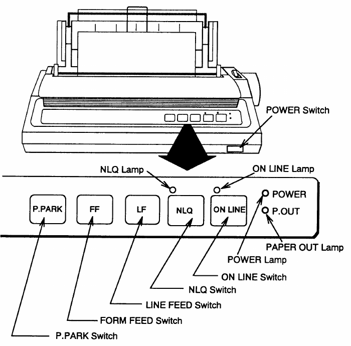
Printer PP-510 (optional supply)
The printer prints transmitted and received messages. The POWER
switch is on the right side of the unit. A lamp on the switch lights
when the power is on. If the paper is set correctly the ON LINE lamp
also lights. When both these lamps are lit the printer is ready to print
information received from the terminal unit. For further details, refer
to the operator's manual of the PP-510.
Figure 1-3 Printer PP-510

1-4
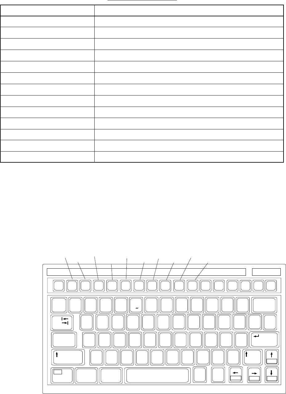
Keyboard
The FELCOM 12 is almost 100% keyboard controlled. Operation is
simplified by the use of menus which you access by pressing func-
tion keys, numbered F1-F10 at the top of the keyboard. Figure 1-4
shows keyboard layout.
~
`2
134 5 67890 - =
_+)*(9*87^&%$#@!
QWERTYUIOP
[]
{}
\
|
ASDF GHJ KL:+
;
"
'
Tab
Caps Lock
ZXCVBNM<> ?/
/
.
,
123
456
0Shift
Fn Ctrl Alt Alt Ctrl
Home End PgDn
PgUp
Shift
Enter
Backspace
Esc F1 F2 F3 F4 F5 F6 F7 F8 F9 F10 Num
Lock
Prt Sc
SysRq
Scroll
Lock Pause
Break
Insert Delete
C
Figure 1-4 Keyboard
Key description
Esc Cancels key input and returns to previous
display screen.
F1-F10 These are the function keys. They select
menus.
Backspace Deletes the character to the left of the cur-
sor.
Insert Works the same as PASTE function. See
page 3-5.
Delete Deletes the character on the cursor.
Home Moves the cursor to the top of a message
being edited.
End Moves the cursor to the bottom of a mes-
sage being edited.
PgUp Goes to the previous page of the edit screen.
PgDn Goes to the next page of the edit screen.
[
/
], [
/
], [
,
], [
/
]Control the cursor.
Enter Registers key input.
1-5
Shift Selects upper or lower case letters. Press and
hold down the key to get upper case letters.
Note that only upper case letters are used in
telex.
Alt Executes the shortcut key operation when
combined with an alphabet key.
Space Bar Inserts a space. In addition, it displays file
list, partial view of a file, etc. depending on
menu.
Caps Lock Turns upper case letter input on or off. CAPS
appears on the display when the keyboard
is set for upper case letter input.
Tab Inserts horizontal tab characters. The num-
ber of tab characters the key can insert per
line of text can be programmed for two, four
or eight tabs.
Ctrl Works in combination with alphabet keys as
follows:
Ctrl key shortcut keys
]M[+lrtC.retnEsaemaS
]H[+lrtC.ecapSkcaBsaemaS
]I[+lrtC.baTsaemaS
]V[+lrtCtresnI+etirwrevOsaemaS
FN Combined with an arrow Key, it scrolls
screen(
/
,
/
),or shifts cursor (
,
,
/
).
Num Lock Turns numeric input on or off. Note that you
cannot enter alphabet when the Num LED
is its.
Note1: In telex, lower case, #, &, *, $ or % are not used. A full list of
characters usable in telex appears on page A-11 in the Appen-
dix.
Note2: C (Euro mark) on 5
%
C key is not used.
1-6
Shortcut key operation
The FELCOM 12 provides the keyboard shortcuts shown below for
commonly used functions.
Table 1-2 Shortcut keys
Operation
Same as NEW in File menu
Same as OPEN in File menu
Same as CLOSE in File menu
Same as DELETE in File menu
Same as SAVE in File menu
Same as PRINT in File menu
Same as UNDO
Same as CUT in Edit menu
Same as COPY in Edit menu
Same as PASTE in Edit menu
Same as Top of Text in Edit/Go to line menu
Same as End of Text in Edit/Go to line menu
Same as CHANGE WINDOW in Edit menu
Short Cut key
ALT+N
ALT+O
ALT+Q
ALT+D
ALT+S
ALT+P
ALT+X
DELETE
ALT+C
INSERT
Fn+b (Home)
Fn+a (End)
ALT+V
Function Menus
The function menus, which you access by pressing the function keys
(F1-F10) at the top of the keyboard, control most operations of this
unit.
~
`2
134 67890 - =
_+)
*
(
9*87
^&$#@!
QWERTYUIOP
[]
{}
\
|
ASDF GHJ KL:+
;
"
'
Tab
Caps Lock
ZXCVBNM<> ?/
/
.
,
123
456
0Shift
Fn Ctrl Alt Alt Ctrl
Home End PgDn
PgUp
Shift
Enter
Backspace
Esc F1 F2 F3 F4 F5 F6 F7 F8 F9 F10
Num
Lock
Prt Sc
SysRq
Scroll
Lock Pause
Break
Insert Delete
File Edit Transmit
EGCReportsLogs OptionsSetup StopAlarm
Position
5
%
C

1-7
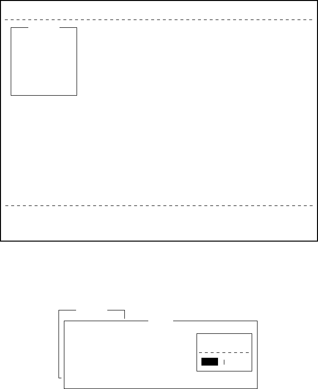
Selecting menu, menu options
Press appropriate function key to select a menu. For example, press
[F1] to select the File menu.
File
1. New
2. Open
3. Close
4. Save
5. Delete
6. Rename
7. Print
8. Format Disk
9. MIME (Decode)
ALT-N
ALT-O
ALT-Q
ALT-S
ALT-D
ALT-P
File Edit Transmit EGC Reports Logs Options Setup Position StopAlarm
Figure 1-6 File menu
You may select menu options with the arrow keys (pressing [Enter]
after making selection) or appropriate numeric key. As the cursor
moves down through a menu, when usings the arrow keys, each menu
option, initially shown as white on black, reverses to black on white.
This highlighting indicates the item is available for selection. In Fig-
ure 1-6, for example, “New” is available for selection.
Function menu description
Table 1-3 Function menu description
uneMnoitpircseD
eliF.selifsessecorP
tidE.seitilicafgnitidetxetsedivorP
timsnarT.segassemstimsnarT
CGE.seitilicafegassemCGEpusteS
stropeR.noitcnufgnitroperatadpusteS
sgoL.sgolegassemeviecerdnadnessyalpsiD
snoitpO.seitilicafgnitset,tuogol,nigoL
puteS.metsysehtpusteS
noitisoP.noitisops'pihsruoysretnE
mralApotS.rezzubsecneliS

1-8
Sample menu operation
For example, you want to display a transmitted message. All opera-
tions begin from the standby display.
File Edit Transmit EGC Reports Logs Options Setup Position StopAlarm
Date
Time
Position
Waypoint
Course
Speed
Current NCS
Current Channel
Current TDM
MES Status
GPS Status
DCE Memory
97-08-04
01:32 (UTC)
LAT
LON
LAT
LON
DEG
KTS
344 (IOR) LOGOUT
NCS CC
NCS CC
Idle
****
32818 Bytes free
BBER
C/N
Send level
RxIF AGC Level
REF Offset Freq
Synthe 1st-1 Local
1st-2 Local
RX2nd Local
Antenna Power Supply
Water Temperature
Water Current
Direction
Speed
Depth
000
OK ( 36dB)
OK ( 0)
OK (135)
OK ( 0Hz)
OK
OK
OK
OK
DEG
DEG
KTS
Current State: IDLE
DCE Ver **
SYNC ( NCS )
NCS: IOR LOGOUT
97-08-04 01:32 (UTC)
Figure 1-7 Standby display
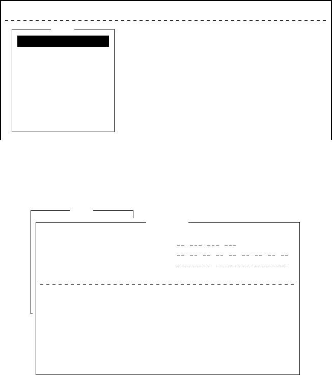
Press [F6] to display the Logs menu.
File Edit Transmit EGC Reports Logs Options Setup Position StopAlarm
1. Send Message Log
2. Receive Message Log
3. EGC Log
4. Log
Log
Figure 1-8 Logs menu
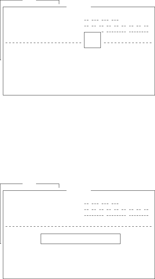
Press [1] to display the send message log.
File Edit Transmit EGC Reports Logs Options Setup Position StopAlarm
No. Message File Station LES Priority Send Status Delivery
Send Message Log
1. Send Message Log
2. Receive Message Log
Log
Figure 1-9 Send message log
Select the message you want to display by pressing [
/
] or [
/
] fol-
lowed by [Enter].
1-9
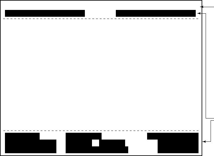
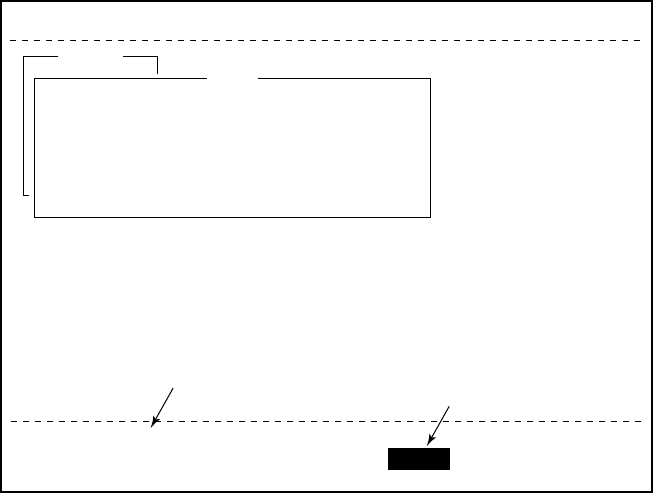
Display Indications
The display is divided in three sections:
1) The menu area
2) The working area
3) The operating status area
File Edit Transmit EGC Reports Logs Options Setup Position StopAlarm
(1) (2)
(3)
(4)
(4)
(5)
(6) (7)
(8)
(9)
(10)
(10)
2 WORKING AREA
1 Function
Menu
3 Operating
Status
Figure 1-10 Location of display indications
Below are indications and their meanings.
(1) Distress alert information
No display (no distress alert)
Distress Alert Activated
Distress Alert Test Activated
Distress Alert Acknowledge Received
Distress Message Call Activated
Distress Message Call Acknowledged
(2) Communication network mode
No display Normal operation
Restoration Mode Problem at NCS.
(blinking)
Restoration Mode Previously designated LES is trans-
(reverse indication) mitting the NCS common channel
signal.
1-10
(3) Communication unit status
Idle Idle (awaiting receiving, awaiting trans-
mitting)
Idle (pending) Awaiting reply from LES
Sending During message transmission
Receiving During receiving
Login Logging in with NCS
Logout Logging out with NCS
Distress Alert When own vessel is transmitting the
distress alert
Data Report During transmission of data report
Testing PV testing
Test Setup Requesting PV testing
Scanning NCS scanning
EGC RECEIVER EGC-only receiver operation
(reverse indication)
Delivery Status Req. When transmitting delivery status re-
quest
Forced Clearing When stopping receiving, transmitting,
or scanning
(4) Communication unit remarks and DCE
version number
This area provides remarks about communication unit status.
(5) Frame synchronization
Blank When changing channel, or during
transmission
SYNC (NCS) Synchronizing with NCS
SYNC (LES) Synchronizing with LES
UNSYNC Out of synchronization
Retuning Synchronizing with NCS or LES
(6) Ocean region receiving
No display Out of synch with satellite
AOR-W Atlantic Ocean Region-West
AOR-E Atlantic Ocean Region-East
IOR Indian Ocean Region
POR Pacific Ocean Region

1-11
(7) Logging status
LOGOUT Logged out with ocean region
LOGIN Logged in with ocean region
LOGIN (blinking) Logging in with ocean region
(8) Other information
No display No receive message in memory, or
printer is operating.
REC. MESSAGE EXISTS Displayed when a routine message has
(blinking) not been printed, or a confidential mes-
sage is received.
DATA REPORT When data reporting is activated.
(Reverse indication)
(9) Date and time display
The date (set at system setting) and time (set by satellite) appear.
Time is updated every minute (with navigator connection).
(10) Ship’s position
Ship’s position (automatic or manual input) appears here.
Error Messages and Alerts
The terminal unit displays error messages and alerts to call your at-
tention to misoperation, failed operation and system error. A list of
error messages and alerts appears on pages A-12 through A-14 in the
Appendix. To erase an error or an alert, press [Esc].
File Edit Transmit EGC Reports Logs Options Setup Position StopAlarm
No. Message File Station LES Priority Send Status Delivery
Send Message Log
1. Send Message Log
2. Receive Message Log
Log
CAUTION
No Message
<Press ESC key to coninue>
Figure 1-11 Location of error messages and alerts

1-12
Silencing the Audible Alarm
Some error messages and alerts are accompanied by the audible alarm.
This alarm can be silenced, in most instances, by pressing any key. If
the alarm cannot be silenced in that manner, go to the Setup menu to
silence it. Note that the distress alert alarm transmitted by own ship
cannot be silenced by either method; it automatically stops when you
receive the distress acknowledge signal from LES.
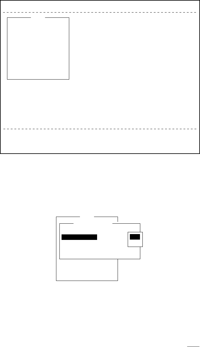
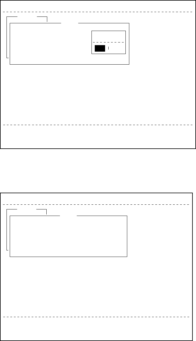
Silencing the alarm by the Setup menu
1. Press [F8] to display the Setup menu.
File Edit Transmit EGC Reports Logs Options Setup Position StopAlarm
Current State: IDLE
DCE Ver **
SYNC ( NCS )
NCS: IOR LOGOUT
97-08-04 01:42 (UTC)
Setup
1. Distress Alert Setup
2. System Setup
3. Editor Setup
4. Terminal Setup
5. EGC Setup
6. Auto Mode Setup
7. E-Mail Setup
8. Directories
9. Configuration
Figure 1-12 Setup menu
2. Press [6] to display the Auto Mode Setup menu.
3. Press [
/
] key to go to the Receive Alarm line.
4. Press [Enter] to open the selection window.
Setup
7. E-Mail Setup
8. Directories
9. Configuration
Auto Mode Setup
ON
OFF
Auto Log Print
Receive Alarm
Auto Telex Msg Save
Auto EGC Msg Save
Figure 1-13 Auto mode setup menu
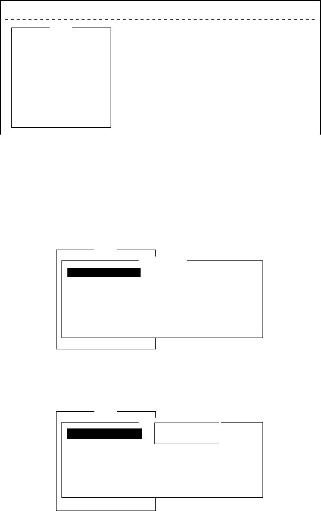
1-13
File Edit Transmit EGC Reports Logs Options Setup Position StopAlarm
Current State: IDLE
DCE Ver **
SYNC ( NCS )
NCS: IOR LOGOUT
97-08-04 01:42 (UTC)
Setup
1. Distress Alert Setup
2. System Setup
3. Editor Setup
4. Terminal Setup
5. EGC Setup
6. Auto Mode Setup
7. E-Mail Setup
8. Directories
9. Configuration
Figure 1-12 Setup menu
2. Press [6] to display the Auto Mode Setup menu.
3. Press [
/
] key to go to the Receive Alarm line.
4. Press [Enter] to open the selection window.
S
e
t
up
7. E-Mail Setup
8. Directories
9. Configuration
Auto Mode Setup
OFF
ON
ON
OFF
ON
Auto Log Print
Receive Alarm
Auto Telex Msg Save
Auto EGC Msg Save
Data Report & Polling Print
ON
OFF
Figure 1-13 Auto mode setup menu
5. Press [
/
] to select OFF.
Note: To silence the audible alarm given to an EGC distress or
urgent message from Distress Alert Unit (IC-302), follow
the above procedure. DO NOT press the DISTRESS button
on the IC-302 to silence the alarm; you will transmit own
ship’s distress alert.
6. Press [Enter] to close the selection window.
7. Press [Esc] twice.
1-14
Contents of program disk
READ.ME: Instructions for installation of software
IBINST.BAT: English software for IB-581
IBRINST.BAT: Russian software for IB-581
PCINST.BAT: English software for PC
PCRINST.BAT: Russian software for PC
INSTALL.BAT: Program start up
FELCOM12.EXE: Terminal software
ENGLISH.DAT: English text definition file
RUSSIAN.DAT: Russian text definition file
ENH_FONT.EXE: Russian driver
DTE.DAT: Terminal software definition file (for PC)
DTE.B: Terminal software definition file (for IB-581)
LES.DAT: LES list
FORMAT.COM: Format disk

2-1
SYSTEM INITIALIZATION
This chapter provides the information necessary for initializing the
FELCOM 12. Once the FELCOM 12 is initialized you need do no
more than press a few keys to get fully automatic transmission and
reception.
Inmarsat assigns each MES an Inmarsat Mobile Number (IMN). The
IMN has already been entered into the FELCOM 12.
System Settings
Two sets of DTEs installed
The communication unit provides two sets of connectors (DTE1, main;
DTE2, 2nd) for connection of two DTEs. It is preset at the factory for
connection with one DTE (main DTE). Main DTE is available to set
the menu.
1. Press [F8] to select the Setup menu.
File Edit Transmit EGC Reports Logs Options Setup Position StopAlarm
Current State: IDLE
DCE Ver **
SYNC ( NCS )
NCS: IOR LOGOUT
97-08-04 01:50 (UTC)
Setup
1. Distress Alert Setup
2. System Setup
3. Editor Setup
4. Terminal Setup
5. EGC Setup
6. Auto Mode Setup
7. E-Mail Setup
8. Directories
9. Configuration
Figure 2-1 Setup menu
Menu Items which cannot be set on 2nd DTE (Sub DTE )are shown
in gray.
2-2
System setup
The System Setup menu provides for input of date, time, operating
mode, and port function.
1. Press [F8] to select the Setup menu.
File Edit Transmit EGC Reports Logs Options Setup Position StopAlarm
Setup
1. Distress Alert Setup
2. System Setup
3. Editor Setup
4. Terminal Setup
5. EGC Setup
6. Auto Mode Setup
7. E-Mail Setup
8. Directories
9. Configuration
Figure 2-4 Setup menu
2. Press [2] to display the System Setup screen.
Note: If the communication unit is off or its interconnection cable
has loosened or is damaged, “No response from communi-
cation unit.” appears.
Setup
9. Configuration
System Setup
01:53 97-08-04 (YY-MM-DD)
IOR
INMARSAT-C
OFF
DTE1
DTE1
DTE1
System Date & Time
Preferred NCS
MES Operation Mode
Nav Port
Active Port
Message Output Port
EGC Output Port
Figure 2-5 System setup menu
3. Press [Enter] to open the date window.
Setup
9. Configuration
System Setup
01:53 97-08-04 (YY-DD)
INMARSAT-C
OFF
ALL
DTE1
DTE1
01:53 97-08-04
System Date & Time
Preferred NCS
MES Operation Mode
Nav Port
Active Port
Message Output Port
EGC Output Port
Figure 2-6 System setup menu, system date & time
4. Enter the date.
5. Press [Enter] to close the window.
6. Press [
/
] to advance the cursor to the Preferred NCS line.
Note: Date cannot be entered in the FFA version.

2-3
7. Press [Enter] to open the selection window.
Setup
9. Configuration
System Setup
01:53 97-08-04 (YY-MM-DD)
IOR
INMARSAT-C
OFF
DTE1
DTE1
Auto
AOR (WEST)
AOR (EAST)
POR
IOR
System Date & Time
Preferred NCS
MES Operation Mode
Nav Port
Active Port
Message Output Port
EGC Output Port
Figure 2-7 System setup menu, preferred NCS
8. Select appropriate NCS (Auto, AOR-West, AOR-East, POR or
IOR) by arrow keys. The FELCOM 12 will search for that NCS
signal each time it is turned on. The Auto setting searches all NCS
signals to find the most suitable NCS; thus, scanning can take
quite some time. (For reference, the coverage range of each satel-
lite is shown in the figure on page 8.)
If you want to change the NCS channel temporarily, refer to “Se-
lecting NCS channel” on page 7-4.
9. Press [Enter] to close the selection window.
10. Press [
/
] to advance the cursor to the MES Operation Mode line.
11. Press [Enter] to open the selection window.
Setup
9. Configuration
System Setup
01:53 97-08-04 (YY-MM-DD)
IOR
INMARSAT-C
OFF
DTE1
DTE1
INMARSAT-C
EGC
System Date & Time
Preferred NCS
MES Operation Mode
Nav Port
Active Port
Message Output Port
EGC Output Port
Figure 2-8 System setup menu, MES operation mode
12. Select operating mode, either Inmarsat C or EGC. The Inmarsat
C setting provides telex communications and operates as an EGC
receiver when not transmitting or receiving. The EGC setting en-
ables EGC-only receiver operation. In this case EGC RECEIVER
appears in reverse indication at the bottom of the screen.
13. Press [Enter] to close the selection window.
14. Press [
/
] to advance the cursor to the Nav Port line.
Note: The MES Operation Mode in the FFA version cannot
be set to other than“Inmarsat C.”
2-4
15. Press [Enter] to open the selection window.
Setup
9. Configuration
System Setup
01:53 97-08-04 (YY-MM-DD)
IOR
INMARSAT-C
DTE1OFF
DTE1
DTE1
OFF
EXT
INT
System Date & Time
Preferred NCS
MES Operation Mode
Nav Port
Active Port
Message Output Port
EGC Output Port
Figure 2-9 System setup menu, nav port
16.Select the navigation device which is interfaced to the
FELCOM 12.
OFF: No connection
EXT: Select this setting when external navigation device is
connected. The FELCOM 12 automatically selects ship’s
position information in the order of GPS, LC, and
DECCA.
INT: Internal GPS board provides position data.
Note: The Nav Port setting in the FFA version cannot be set to
other “INT.”
Note: If there is no navigation equipment connection (Nav Port
setting is “OFF”), you should input dead reckoning posi-
tion in the Position menu. Refer to page 2-26.
17. Press [Enter] to close the selection window.
18. Press [
/
] to advance the cursor to the Active Port line.
19. Press [Enter] to open the selection window.
Setup
9. Configuration
System Setup
01:53 97-08-04 (YY-MM-DD)
IOR
INMARSAT-C
OFF
DTE1
DTE1
DTE1
ALL
System Date & Time
Preferred NCS
MES Operation Mode
Nav Port
Active Port
Message Output Port
EGC Output Port
Figure 2-10 System setup menu, active port
20. Select active port (DTE); “DTE1” or “ALL”.
DTE1: Only DTE1 is active.
ALL: DTE1, DTE2 and PC/DATA are active.
21. Press [Enter] to close the selection window.
22. Press [
/
] to send the cursor to the Message Output Port line.

2-5
23. Press [Enter] to open the selection window.
Setup
9. Configuration
System Setup
01:53 97-08-04 (YY-MM-DD)
IOR
INMARSAT-C
DTE1
OFF
DTE1
System Date & Time
Preferred NCS
MES Operation Mode
Active Port
Nav Port
Message Output Port
EGC Output Port DTE1
DTE2
PC/DATA
AUTO
Figure 2-11 System setup menu, message output port
24. Select the DTE where you want to store receive messages.
DTE1: All receive messages are routed to the main DTE
(connected to DTE1 on the communication unit)
regardless of sub address.
DTE2: All receive messages are routed to the 2nd DTE
(connected to DTE2 on the communication unit)
regardless of sub address.
PC/DATA: All receive messages are routed to the PC/DATA
(connected to PC/DATA on the communication unit)
regardless of sub address (not used).
AUTO: Select to route messages with sub address 000 to
the main DTE, and messages with the sub address
of the 2nd DTE to the 2nd DTE. All other mes-
sages are routed to the main DTE.
Note: Do not select DTE2 or Auto when there is no DTE con-
nected to the DTE2 port; messages cannot be read from
the communications unit.
25. Press [Enter] to close the selection window.
26. Press [
/
] to advance the cursor to the EGC Output Port line.
27. Press [Enter] to open the selection window.
Setup
9. Configuration
System Setup
01:53 97-08-04 (YY-MM-DD)
IOR
INMARSAT-C
OFF
DTE1
DTE1
System Date & Time
Preferred NCS
MES Operation Mode
Nav Port
Active Port
Message Output Port
EGC Output Port DTE1
DTE1+DTE2
Figure 2-12 System setup menu, EGC output port
28. Select the DTE where you want to store receive EGC messages;
DTE1, DTE2 or PC/DATA.
29. Press [Enter] to close the selection window.

2-6
30. Press [Esc] to open the update window.
Setup
9. Configuration
System Setup
System Date & Time
Preferred NCS
MES Operation Mode
Nav Port
Active Port
Message Output Port
EGC Output Port
01:53 97-08-04 (YY-MM-DD)
IOR
INMARSAT-C
OFF
DTE1
DTE1
DTE1
Update
Yes No
Figure 2-13 System setup menu, update
31. Press [Enter] to select “Yes”.
32. Press [Esc] to register all system setup settings and return to the
standby display.
Terminal Setup
Terminal Setup menu provide for date display format,screen saver
and display mode.
1. Press [F8] to select the Setup menu.
2. Press [4] to display the Terminal Setup screen.
Terminal Setup
Date Disp. Form
Screen Saver
Display Mode
YY-MM-DD
ON
Normal Mode
Figure 2-14 Terminal Set up menu.
3. Press [Enter] to open the selection window.
4. Select date display format “YY-MM-DD(year-month-day)”,
“ MMM-DD-YY(month-day-year )” or “ DD-MMM-YY(day -
month -year)”.
5. Press [Enter] to close the selection window.
6. Press [
/
] to advance the cursor to the Screen Saver line.
7. Press [Enter] to open the selection window.
8. Select “ON” or “OFF”.
9. Press [Enter] to close the selection window.
10. Press [
/
] to advance the cursor to the Display Mode line.
11. Press [Enter] to open the selection window.

2-7
12. Select “Normal Mode” or “Reverse Mode”.
Normal Mode displays black characters on white
backgrund.
Reverse Mode displays white characters on black
backgrund.
13. Press [Enter] to close the selection window.
14 Press [Esc] to return to the standby display.
Login and Logout
Each time the DTE and communication unit are turned on register
your vessel with the Inmarsat C system, to enable communications
between your vessel and LES. This is called login. The first time you
login you must do it manually; thereafter the NCS does it for you
automatically, even when you move to another ocean region.
Note that the distress alert can be transmitted and EGC messages
received regardless of whether you are logged in or not.
If you will not be using the FELCOM 12 for a prolonged period
you should logout from the Inmarsat C system, before turning
off the power to the communication unit. The Inmarsat C system
will then register you as inactive, notifying anyone trying to call you
that you are currently unavailable. If you do not log out before turn-
ing off the power, the LES may attempt to send a message to you. It
may charge your correspondent, even if you never receive the
message.
Note: The communication unit should be idle (“Current State: IDLE”
appears at the bottom of the screen) to login and logout.
Note: When the FFA version is active, vessel is automatically logged
in when the power is turned on.
2-8
Login
1. Confirm that “SYNC (NCS)” appears at the bottom of the screen.
2. Press [F7] to display the Options menu.
File Edit Transmit EGC Reports Logs Options Setup Position StopAlarm
Current State: IDLE
DCE Ver **
SYNC ( NCS )
NCS: IOR LOGOUT
97-08-04 02:01 (UTC)
1. Login
2. Logout
3. Abort
4. Select NCS
5. Ocean Region
6. Test
Options
Figure 2-15 Options menu
3. Press [1] to display the Login screen.
Options
Login
Start
No
Yes
Yes
Figure 2-16 Login screen
Note: The communication unit must be idle to login. When it is
not idle, “Communication Unit is not IDLE now. Cannot
start login.” appears. Press any key to return to the standby
display. Wait until the communication unit becomes idle.
4. Press [Enter] to start login.
2-9
5. LOGIN begins and the screen should now look something like
Figure 2-17. The indication LOGIN appears in blinking reverse
video.
File Edit Transmit EGC Reports Logs Options Setup Position StopAlarm
Current State: LOGIN
CALLING
DCE Ver **
97-08-04 02:02 (UTC)
LAT:
LON:
LOGIN replaces IDLE. Blinking during login
SYNC ( NCS )
NCS: IOR LOGIN
Options
Login
Starting Login Process.
Press any key to escape.
Figure 2-17 Appearance of display screen during login
6. When login is completed, “Successful login” appears. The com-
munication unit goes into Idle state, LOGIN stops blinking and
the ocean region you logged in with appears on the screen.
7. Press any key to return to the standby display.
Logout
1. Press [F7] to display the Options menu.
2. Press [2] to display the logout screen.
Note: The communication unit must be idle to logout. When it is
not idle, “Communication Unit is not IDLE now. Cannot
start logout.” appears. Press any key to return to the standby
display. Wait until the communication unit becomes idle.
2-10
File Edit Transmit EGC Reports Logs Options Setup Position StopAlarm
Current State: IDLE
Successful Login.
DCE Ver **
SYNC ( NCS )
NCS: IOR LOGIN
97-08-04 02:04 (UTC)
LAT:
LON:
Options
Logout
Start
Yes No
Figure 2-18 Options menu, logout screen
3. Press [Enter] to start logout. Logout begins and the screen now
looks something like Figure 2-19.
File Edit Transmit EGC Reports Logs Options Setup Position StopAlarm
Current State: LOGOUT
CALLING
DCE Ver **
97-08-04 02:02 (UTC)
LAT:
LON:
SYNC ( NCS )
NCS: IOR LOGOUT
Options
Logout
Starting Logout Process.
Press any key to escape.
Figure 2-19 Appearance of display screen during logout
4. When logout is completed, “Successful logout” appears. The Cur-
rent State returns to IDLE.
5. Now you can turn off the power of the FELCOM 12.
Note: In the FFA version, the display shows the message“INF:
Logout request accepted. plase wait.”

2-11
EGC Settings
What is the EGC (Enhanced Group Call) service?
The EGC service enables EGC information providers to send
SafetyNETTM or FleetNETTM messages via a LES to select groups of
ships, or to all ships within a defined geographical area.
To send an EGC message, the information provider prepares the mes-
sage, and then accesses the Country of international telex network to
send the message to the LES. The LES processes and forwards it to
the NCS for the ocean region designated by the provider. Then, NCS
broadcasts the message throughout the ocean region.
Although all MESs can receive the EGC message, the message is
accepted only by those receivers that have been pre-programmed for
the area or group conditions contained in the message. All other EGC
receivers reject the message.
Two EGC services are available:
1) SafetyNETTM
This provides a means for information providers to distribute Mari-
time Safety Information (MSI) from shore-to-ship. Authorized in-
formation providers include:
a. Hydrographic Offices, for navigational warnings
b. National Weather Services, for meteorological warnings and
forecasts
c. Rescue Co-ordination Center, for shore-to-ship distress alerts
and other urgent information
d. International Ice Patrol, for North Atlantic ice hazards
2) FleetNETTM
This service allows authorized information providers such as com-
mercial subscription services, shipping companies and govern-
ments, which have registered with a LES that supports
FleetNETTM, to broadcast messages to selected group of MESs.
Typical applications of FleetNETTM are:
a. Fleet or company broadcasts
b. News broadcasts
c. Commercial weather services
d. Market quotations
e. Government broadcasts to all vessels on a country’s registra-
tion
2-12
EGC setup
The FELCOM 12 receives EGC messages directed to its present po-
sition and Navarea without further programming. The EGC Setup
screen lets you select additional areas for which you wish to receive
messages and also the Navtex station and type of message for Coastal
Warning (NAVTEX Re-broadcast).
1. Press [F8] to display the Setup menu.
File Edit Transmit EGC Reports Logs Options Setup Position StopAlarm
Setup
1. Distress Alert Setup
2. System Setup
3. Editor Setup
4. Terminal Setup
5. EGC Setup
6. Auto Mode Setup
7. E-Mail Setup
8. Directories
9. Configuration
Figure 2-20 Setup menu
2. Press [5] to display the EGC Setup screen.
Setup
EGC Setup
Receive EGC Area
Additional Position
Navarea
Fixed Area
Waypoint (from NAV Equipment)
NAVTEX
Station Code
Type of Message (Can’t reject other report)
Ice reports
Meteo. forecasts
Pilot service
DECCA messages
LORAN messages
OFF
OFF
OFF
OFF
OFF
OMEGA messages
SATNAV messages
Other navaid msg
QRU (no message)
OFF
OFF
OFF
OFF
: :
OFF
Figure 2-21 EGC setup screen
The cursor is on the Additional Position line, where you can enter
L/L position of an ocean region you want to receive broadcasts
for.
3. Press [Enter] to open the additional position window.
4. Enter positions as follows.
a) Enter latitude.
b) Enter [N] or [S].
c) Enter longitude.
d) Enter [E] or [W].

2-13
5. Press [Enter] to close the position window.
6. Press [
/
] to send the cursor to the Navarea line.
7. Press [Enter] to open the Navarea window.
Setup
EGC Setup
Receive EGC Area
Additional Position
Navarea
Fixed Area
Waypoint (from NAV Equipment)
NAVTEX
Station Code
Type of Message (Can’t reject other report)
Ice reports
Meteo. forecasts
Pilot service
DECCA messages
LORAN messages
OFF
OFF
OFF
OFF
OFF
OMEGA messages
SATNAV messages
Other navaid msg
QRU (no message)
OFF
OFF
OFF
OFF
: :
OFF
Figure 2-22 EGC setup screen, Navarea window
8. Enter additional Navarea(s) (up to nine) for which you want to
receive broadcasts. Figure 2-23 shows the Navareas of the world.
Referring to the figure below for numeral and alphabet, enter ad-
ditional Navareas (up to nine) for which you want to receive broad-
casts.
Figure 2-23 Navareas
9. Press [Enter] to close the Navarea window.
10. Press [
/
] to send the cursor to Fixed Area.
11. This line is where you enter fixed areas (max. 3) for chart correc-
tion service. However, this service is not yet available; enter no
data.
12. Press [
/
] to send the cursor to the Waypoint line.
2-14
13. Press [Enter] to open the Waypoint window.
Setup
EGC Setup
Receive EGC Area
Additional Position
Navarea
Fixed Area
Waypoint (from NAV Equipment)
NAVTEX
Station Code
Type of Message (Can’t reject other report)
Ice reports
Meteo. forecasts
Pilot service
DECCA messages
LORAN messages
OFF
OFF
OFF
OFF
OFF
OMEGA messages
SATNAV messages
Other navaid msg
QRU (no message)
OFF
OFF
OFF
OFF
: :
OFFON
OFF
Figure 2-24 EGC setup screen, waypoint
14.Select ON to receive broadcasts for the area of a destination
waypoint selected on the navigation device.
15. Press [Enter] to close the Waypoint window.
16. Press [
/
] to advance the cursor to the Station Code line.
17. Press [Enter] to open the Station Code window.
Setup
EGC Setup
Receive EGC Area
Additional Position
Navarea
Fixed Area
Waypoint (from NAV Equipment)
NAVTEX
Station Code
Type of Message (Can’t reject other report)
Ice reports
Meteo. forecasts
Pilot service
DECCA messages
LORAN messages
OFF
OFF
OFF
OFF
OFF
OMEGA messages
SATNAV messages
Other navaid msg
QRU (no message)
OFF
OFF
OFF
OFF
: :
OFF
Figure 2-25 EGC setup, station code
18. Enter the navtex station code (A-Z) of the navarea. For details
about navtex stations, consult the operator’s manual of the navtex
receiver.
19. Press [Enter] to close the Station Code window.
20.Using the up/down arrow keys enable/disable reception of
NAVTEX broadcasts and press [Enter].
Note that navtex message types “Coastal navigational informa-
tion”, “Meteorological warning” and “Search and rescue alert”
(they do not appear on the display) cannot be deleted since they
are considered essential to navigation.
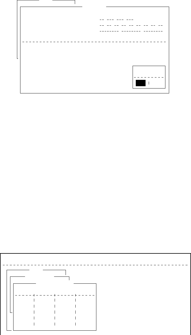
2-15
21. Press [Esc] to open the update window.
Setup
EGC Setup
Receive EGC Area
Additional Position
Navarea
Fixed Area
Waypoint (from NAV Equipment)
NAVTEX
Station Code
Type of Message (Can’t reject other report)
Ice reports
Meteo. forecasts
Pilot service
DECCA messages
LORAN messages
OFF
OFF
OFF
OFF
OFF
OMEGA messages
SATNAV messages
Other navaid msg
QRU (no message)
OFF
OFF
OFF
OFF
: :
OFF
Update
Yes No
Figure 2-26 EGC setup screen, update window
22. Press [Enter] to select “Yes” and register all EGC settings.
23. Press [Esc] to return to the standby display.
Programming EGC channels
The EGC Channel List in the Setup menu stores EGC channels.
There are currently four EGC channels, one for each satellite. These
four channels are pre-programmed into the unit and marked in the
EGC Channel List with asterisks. When more EGC channels become
available you can add them to the list.
1. Press [F8] to display the Setup menu.
2. Press [9] to display the Configuration menu.
3. Press [3] to display the EGC Channel List.
File Edit Transmit EGC Reports Logs Options Setup Position StopAlarm
Setup
Configuration
EGC Channel List
11080* 12580* 10840* 11088*
ENT: set ESC: quit
Figure 2-27 EGC channel list
4. Current EGC channels are marked with an asterisk. These chan-
nels cannot be changed.
5. With the arrow keys place the cursor where there is no data en-
tered.

2-16
6. Press [Enter] to open the text window.
Setup
Configuration
EGC Channel List
11080* 12580* 10840* 11088*
ENT: set ESC: quit
Figure 2-28 EGC channel list, cursor displayed
7. Enter EGC channel frequency code.
8. Press [Enter] to close the text window.
9. Press [Esc] to open the update window.
Setup
Configuration
EGC Channel List
11080* 12580* 10840* 11088*
ENT: set ESC: quit
Update
Yes No
Figure 2-29 EGC channel list, update window
10. Select “Yes” and press [Enter] to register input.
Note: The EGC channel frequency code range is 8000-14000.
Any frequency code entered which is out of this range will
display "Input Error: Channel No." Clear the error mes-
sage by pressing the [Esc] key. Place the cursor at the in-
valid frequency. Then, press the [Enter] key and enter
correct frequency.
Programming NCS Channels
This section shows you how to add NCS channels to the NCS Chan-
nel List. Up to 19 channels can be listed per each ocean region. Cur-
rently, there are four NCS channels, and they are marked with asterisks
in the list.
Below is the procedure for adding NCS channels, when they become
available.
1. Press [F8] to display the Setup menu.
2. Press [9] to display the Configuration menu.
3. Press [4] to display the NCS Channel List.
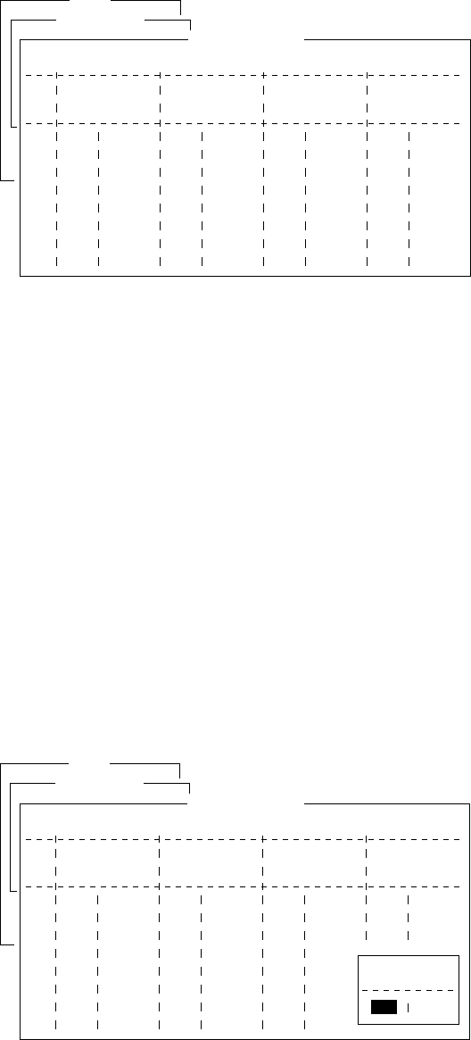
2-17
Setup
Configuration
NCS Channel List
No AOR (WEST)
FREQ
11080*
ID
044
0
0
0
0
0
0
0
1
2
3
4
5
6
7
8
ENT: set ESC: quit
AOR (EAST)
FREQ
12580*
ID
144
1
1
1
1
1
1
1
POR
FREQ
12580*
ID
244
2
2
2
2
2
2
2
IOR
FREQ
10840*
ID
344
3
3
3
3
3
3
3
Figure 2-30 NCS channel list
4. Current NCS common channels are marked with an asterisk. These
channels cannot be changed.
5. Place the cursor where there is no data entered.
6. Press [Enter] to open the text window.
7. Enter NCS channel ID number.
8. Press [Enter] to close the text window.
9. With [
/
] advance the cursor to the frequency column.
10. Press [Enter] to open the text window.
11. Enter NCS channel frequency code.
12. Press [Enter] to close the text window.
13. Press [Esc] to open the update window.
Setup
Configuration
NCS Channel List
No AOR (WEST)
FREQ
11080*
ID
044
0
0
0
0
0
0
0
1
2
3
4
5
6
7
8
ENT: set ESC: quit
AOR (EAST)
FREQ
12580*
ID
144
1
1
1
1
1
1
1
POR
FREQ
12580*
ID
244
2
2
2
2
2
2
2
IOR
FREQ
10840*
ID
344
3
3
3
3
3
3
3
Update
Yes
Yes
No
Yes
Yes
Figure 2-31 NCS channel list, update window
14. Press [Enter] to register input.
Note: The ID number range is 45-63 and the frequency code range
is 8000-14000. Any ID or frequency entered which is out of
those range will display "Input Error: NCS ID" (for in-
valid ID) or "Input Error: Channel No." (For invalid fre-
quency). Clear the error message by pressing the [Esc] key.
Place the cursor at the invalid ID or frequency code. Then,
press the [Enter] key and enter correct ID or frequency.
15. Press [Esc].

2-18
LES List Operations
The LES List provides for storage of 44 LES names per ocean re-
gion. When the LES table is opened on the Send menu, LES names
entered in this LES List appear along with their IDs. See page 2-21.
Programming the LES list
1. Press [F8] to display the Setup menu.
File Edit Transmit EGC Reports Logs Options Setup Position StopAlarm
Setup
1. Distress Alert Setup
2. System Setup
3. Editor Setup
4. Terminal Setup
5. EGC Setup
6. Auto Mode Setup
7. E-Mail Setup
8. Directories
9. Configuration
Figure 2-32 Setup menu
2. Press [9] to display the Configuration menu.
Setup
8. Directories
9. Configuration
Configuration
1. Station List
2. LES List
3. EGC Channel List
4. NCS Channel List
5. E-Mail Service List
Figure 2-33 Configuration menu
3. Press [2] to display the LES List.
Setup
Configuration
LES List
SOUTHBURY
GOONHILLY
Ctrl+P: print ENT: list entry ESC: quit
AOR (WEST)
Name
SOUTHBURY
GOONHILLY
FUCINO
AOR (EAST)
Name
SANTA PAULA
YAMAGUCHI
KUMSAN
POR
Name
YAMAGUCHI
EIK
THERMOPYLAE
ARVI
KUMSAN
IOR
Name
No
1
2
3
4
5
6
7
8
Figure 2-34 LES list
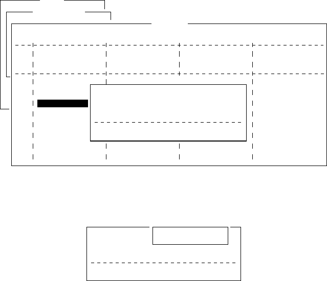
2-19
4. With the arrow keys place the cursor where no data is entered.
5. Press [Enter].
Setup
Configuration
LES List
SOUTHBURY
GOONHILLY
Ctrl+P: print ENT: list entry ESC: quit
AOR (WEST)
Name
SOUTHBURY
GOONHILLY
FUCINO
AOR (EAST)
Name
SANTA PAULA
YAMAGUCHI
KUMSAN
POR
Name
YAMAGUCHI
EIK
THERMOPYAE
ARVI
KUMSAN
IOR
Name
No
1
2
3
4
5
6
7
8
Name
ID
Remarks
Erase the Name to delete this LES.
:
:
:
Figure 2-35 LES list, LES entry window
6. Press [Enter] to open the text window.
Name
ID
Remarks
Erase the Name to delete this LES.
:
:
:
Figure 2-36 LES list, text window
7. Enter LES name (maximum 15 characters).
8. Press [Enter].
9. Press [
/
] to advance the cursor to the ID line.
10. Press [Enter].
11. Enter LES ID. The table on page 2-21 shows all current LES IDs.
12. Press [Enter].
13. Press [
/
] to send the cursor to the Remarks line.
14. If desired, enter remarks (up to 20 characters).
15. Press [Esc] to register LES.
16. To return to the standby display, press [Esc] three times.

2-20
Deleting and changing the LES list
1. Press [F8], [9] and [2] to display the LES list.
2. Select the LES you want to edit.
3. Press [Enter].
The cursor should be on the Name line.
: Yamaguchi
: 303
: KDD Japan......
Name
ID
Remarks
Erase the Name to delete this CES.
Figure 2-37 LES selected from LES list
4. Press [Enter] again to open the window for name entry.
5. To delete/change the LES name, press [Backspace] to erase name
and then press [Enter].
6. To edit an entry, place the cursor on the item you want to edit,
press [Enter], delete with the [Backspace] key, then enter new
data.
7. Press [Esc] to save changes.
8. To return to the standby display, press [Esc] twice.
Printing the LES list
1. Press [F8], [9] and [2] to display the LES list.
2. While pressing and holding down [Ctrl], press [P] to print the
LES list.
LES List ( Printed at 97-08-04 02:33 )
+++++ AOR (WEST) ++++
No.
01
02
12
+++++ AOR (EAST) +++++
No.
01
Name
SOUTHBURY
GOONHILLY
STATION12
Name
SOUTHBURY
LES ID
001
002
012
LES ID
101
Remarks
USA
UK (NCS, ID044)
NETHERLANDS
Remarks
USA
Figure 2-38 Sample LES list printout
3. To return to the standby display, press [Esc] three times.

2-21
Table 2-1 LES IDs
Land earth station operator Countr
y
AOR- E AOR- W IOR POR
Bei
j
in
g
Marine China 311 211
Beze
q
Israel 127 327
CAT Thailand 319
CP Radio Marconi Portu
g
al 118
Embratel Brazil 114
France Telecom France 121 021 321 221
France Telecom
(
Ex DeteSat
)
France 115 333
KDDI Ja
p
an 103 003 303 203
Korea Telecom South Korea 308 208
Morvias
p
utnik
(
Nudel Les
)
Russia 117 317
OTE Greece 120 305
Polish Telecom Poland 116 316
Saudi Telecom Co Saudi Arabia 125 325
Sin
g
a
p
ore Telecom Sin
g
a
p
ore 328 210
Stratos Mobile Networks Canada 102 002 302 202
Telecom Com
p
an
y
of Iran Iran 314
Telecom Italia Ital
y
105 335
Telenor Satellite Services Inc USA 101 001 201
Telenor Satellite Services AS Norwa
y
104 004 304 204
Turk Telecom Turke
y
110 310
Vishi
p
el Vietnam 330
VSNL India 306
Xantic Netherlands 112 012 312 212
Xantic Australia 122 022 322 222
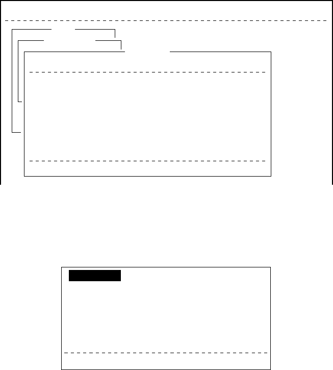
2-22
Station List Operations
Programming the station list
The FELCOM 12 provides an “address book” for programming 64
station IDs.
1. Press [F8] to display the Setup menu.
2. Press [9] to display the Configuration menu.
3. Press [1] to display the Station List.
Setup
Configuration
Station List
01
02
03
04
05
06
07
08
abc
xyz
Seagull
Ctrl+P: print
E-Mail
E-Mail
TELEX
abc@ furuno.co.jp
xyz@ furuno.co.jp
584 463609999
Station Name Type Code, ID / Address
File Edit Transmit EGC Reports Logs Options Setup Position StopAlarm
Figure 2-39 Sample station list
4. Operate [
/
] to place the cursor on a blank line.
5. Press [Enter].
TELEX
Station Name
Destination Type
Prefix Code
Country Code
Station ID
Modem Type
E-Mail Address
Remarks
Erase the Name to delete this station.
Figure 2-40 Entering a station
6. Press [Enter] to open the window for station name entry.
7. Enter name of station, using up to 15 characters.
8. Press [Enter] to close the window.
9. Press [
/
] to send the cursor to the Destination Type line.

2-23
10. Press [Enter] to open the destination type window.
TELEX
FAX
E-Mail
CSDN
PSDN
X400
DNID
SPEC
TELEX (Prefixed)
FAX (Prefixed)
PSDN (Prefixed)
X400 (Prefixed)
DNID (Prefixed)
SPEC (Prefixed)
Figure 3-41 Selection window for “destination type”
TELEX: Telex communication
FAX: Facsimile service
- to an office facsimile machine
E-Mail: E-mail (electronic mail) Service
CSDN: Circuit Switched Data Network-not used.
PSDN: Packet Switched Data Network
-to an office computer via a data network using X.25
standard.
X400: For future use
DNID: Data Network ID -not used.
SPEC: Ship-to shore requests for safety service, accessed by us-
ing special 2-digit codes (See Note 2 below.)
Note 1: When FAX is selected, select “T30 (FAX)” in the “Mo-
dem Type” selection display. For further details, refer to
page 4-2.
Note 2: When SPEC is selected on the Type line, the Country
Code line disappears. Enter two-digit codes on the Sta-
tion ID line. Refer to page 4-18 for further details.
11. Set up according to Destination Type selection. The steps which
follow show how to set up for TELEX (Prefixed).
12. Press [Enter] to close the destination type window.
13. [
/
] to advance the cursor to the Prefix Code line for prefixed.
14. Press [Enter] to open the prefix code window.
15. Key in prefix code in two digits.
Note that some services may not be available depending on LES.

2-24
edoCxiferPnoitcnuF
11ecnatsissAs'rotarepO
21ediuGlaiD
33ecnatsissAlacinhceT
19tseTxeleTcitamotuA
16. Press [Enter] to close the prefix code window.
17. Press [
/
] to advance the cursor to the Country Code line for
TELEX, FAX, PSDN.
18. For ship-to-shore telex, enter international telex country code; ship-
to-ship telex, enter ocean region. A list of international telex coun-
try codes begins on page A-1 in the Appendix.
Ocean Region
AOR-East: 581
POR: 582
IOR: 583
AOR-West: 584
19. Press [Enter] to close the window.
20. Press [
/
] to send the cursor to the Station ID line.
21. Press [Enter] to open the window for station ID entry.
22. Enter telex subscriber number (for land) or MES Inmarsat Mo-
bile Number (for ship).
Up to 15 characters, including space, can be entered.
23. Press [Enter] to close the window.
24. Press [
/
] to advance the cursor to the Remarks line.
25. Press [Enter] to open the window for remarks entry.
26. If desired, enter remarks (up to 20 characters).
27. Press [Enter] to close the window.
28. To return to the standby display, press [Esc] three times.

2-25
Editing the station list
1. Press [F8], [9] and [1] to display the Station List.
Setup
Configuration
Station List
01
02
03
04
05
06
07
08
abc
xyz
Seagull
Ctrl+P: print
E-Mail
E-Mail
TELEX
abc@ furuno.co.jp
xyz@ furuno.co.jp
584 463609999
Station Name Type Code, ID / Address
File Edit Transmit EGC Reports Logs Options Setup Position StopAlarm
Figure 2-42 Station list
2. Press [
/
] and [Enter] to select the station you want to edit.
3. Press [Enter] to open the station name window.
4. To delete a station, press [Backspace] to erase station name, and
then press [Enter].
5. To edit a station name, place the cursor on the character you want
to edit. Press [Backspace] to erase that character, then enter cor-
rect character.
6. Press [Enter] to save changes.
7. If necessary, select other item, edit it and press [Enter].
8. To return to the standby display, press [Esc] four times.
Printing the station list
1. Press [F8], [9] and [1] to display the Station List.
2. While pressing and holding down [Ctrl], press [P].
No.
01
02
03
Name
abc
xyz
Seagull
Type
E-Mail
E-Mail
TELEX
Dest, ID, Modem / Address
abc@ furuno.co.jp
xyz@ furuno.co.jp
584 463609999
Station List ( Printed at 97-08-04 02:38 ) Remarks
Station Name Subscriber s Number
Country Code
Figure 2-43 Sample station list printout
3. To return to the standby display, press [Esc] three times.
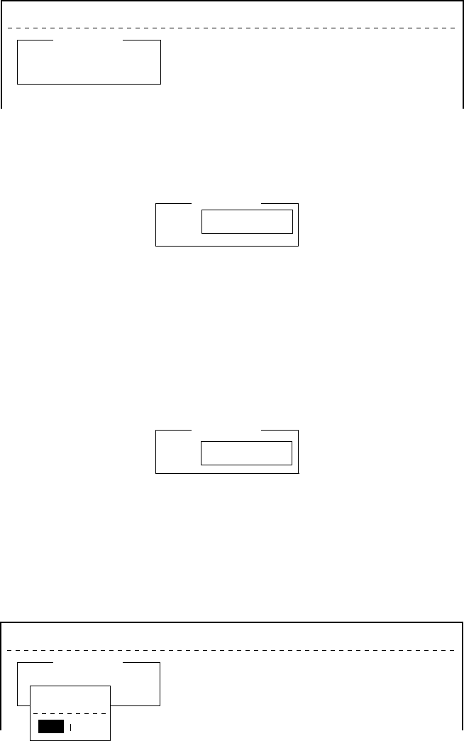
2-26
Entering Own Ship’s Position
When there is no navigation device connected, select OFF on the
Nav Port line in the System Setup menu, as explained on page 2-4,
and enter ship’s position manually as follows:
1. Press [F9] to display the Position menu.
File Edit Transmit EGC Reports Logs Options Setup Position StopAlarm
Ship Position
LAT
LON
00:00.00N
000:00.00E
Figure 2-44 Ship position
2. Press [Enter] to open the window for latitude entry.
00:00.00N
000:00.00E
Ship Position
LAT
LON 00:00.00N
Figure 2-45 Ship position, window for entering position
3. Enter latitude and [N] or [S].
4. Press [Enter] to close the window.
5. Press [
/
] to send the cursor to the LON line.
6. Press [Enter] to open the window for longitude entry.
00:00.00N
000:00.00E
Ship Position
LAT
LON 000:00.00E
Figure 2-46 Ship position
7. Enter longitude and [E] or [W].
8. Press [Enter] to close the window.
9. Press [Esc] to open the update window.
File Edit Transmit EGC Reports Logs Options Setup Position StopAlarm
Ship Position
LAT
LON
00:00.00N
000:00.00E
Update
No
Yes
Yes
Figure 2-47 Ship position, update
10. Press [Enter] to close Ship Position menu.
This position data is also entered on the “Update Distress Alert”
screen. (Refer to page 6-1.)
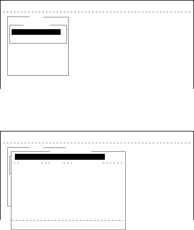
2-27
Setting Directories
You can designate the directory where to save incoming and outgo-
ing messages as follows:
1. Press [F8] to display the Setup menu.
2. Press [8] to display the Directories menu.
Setup
File Edit Transmit EGC Reports Logs Options Setup Position StopAlarm
5. EGC Setup
6. Auto Mode Setup
7. E-Mail Setup
8. Directories
9. Configuration
Directories
Message Directory
EGC Message Directory
Figure 2-48 Setup menu, directories
3. Press [Enter] to select “Message Directory”.
Message Directory appears in the command line.
Setup
File Edit Transmit EGC Reports Logs Options Setup Position StopAlarm
5. EGC Setup
6. Auto Mode Setup
7. E-Mail Setup
8. Directories
9. Configuration
Directories
Message Directory
EGC M<DIR><essag>456ABC <DIR>
e <DIDirectory
Message Directory
To View: SPACE Make Dir: INS Remove Dir: DEL
456
901
42
42
868
372
6794
97-07-28 20:53
97-07-28 20:54
97-07-15 02:13
97-07-14 05:42
97-07-15 02:33
97-07-15 02:52
97-07-15 02:59
97-07-15 03:13
Filename Size Date & Time
ABC <DIR>
ABC281 .
COIEKI .
COMTEST
.
E0970715.001
E0970715.002
E0970715.003
E0970715.004
75 Files exist 578560 bytes free
[B:\ ]
Figure 2-49 Setup menu, directories, message directory
4. Press [
/
] to select a directory name.
5. Press [Insert] to make a new directory name.
6. Type a new directory name (for example, MESSAGE).
7. Press [Enter].
8. Press [ ] .
9. Press [Enter] to select directory name.
10. Press [Esc] twice to return to standby.
/
2-28
E-mail Service List
The E-mail service list provides for E-mail set up. Currently there are
four service stations which handle E-mail. The procedure below de-
scribes how to add service stations to the list.
1. Press [F8] to display the Setup menu.
2. Press [9] to display the Configuration menu.
Setup
8. Directories
9. Configuration
Configuration
1. Station List
2. LES List
3. EGC Channel List
4. NCS Channel List
5. E-Mail Service List
Figure 2-50 Setup menu, configuration
3. Press [5] to display the E-mail Service List.
Setup
8. Directories
9. Configuration
Configuration
1. Station List
2. LES List
3. EGC Channel List
4. NCS Channel List
5. E-Mail Service List
E-Mail Service List
Station Name
01
02
03
04
05
06
07
08
AOR.W AOR.E POR IOR
Comsat
PTT Telecom
British Telecom
Stratos
Telstra
EIK
001 101 201 321
012 112 212 312
002 102 202 302
022 122 222 322
022 122 222 322
004 104 304
Figure 2-51 Setup menu, configuration, E-Mail Service List
4. Select blank space in Station Name column and press [Enter].
E-mail setup display appears.
Setup
8. Directories
9. Configuration
Configuration
1. Station List
2. LES List
3. EGC Channel List
4. NCS Channel List
5. E-Mail Service List
E-Mail Service List
Station Name
01
02
03
04
05
06
07
08
AOR.W AOR.E POR IOR
Comsat
PTT Telecom
British Telecom
Stratos
Telstra
EIK
001 101 201
012 112 212 312
002 102 210
022 122 222 322
Service Station Name
Service ID
LES ID(AORW)
(AORE)
(POR)
(IOR)
To:
Cc:
Subject:
Separator
Attach File(MIME) ON
Figure 2-52 E-mail setup

2-29
5. Press [Enter] to open the window for service station name entry.
Setup
8. Directories
9. Configuration
Configuration
1. Station List
2. LES List
3. EGC Channel List
4. NCS Channel List
5. E-Mail Service List
E-Mail Service List
Station Name
01
02
03
04
05
06
07
08
AOR.W AOR.E POR IOR
Comsat
PTT Telecom
British Telecom
Stratos
Telstra
EIK
001 101 201
012 112 212 312
002 102 210
022 122 222 322
Service Station Name
Service ID
LES ID(AORW)
(AORE)
(POR)
(IOR)
To:
Cc:
Subject:
Separator
Attach File(MIME) ON
Figure 2-53 Service station list
6. Type service station name.
7. Press [Enter] to close the window.
8. Press [
/
] to place the cursor on the Service ID line.
9. Press [Enter] to open the window for service ID entry.
10. Type Service ID.
Service ID is station address .
11. Press [Enter] to close the window.
12. Press [
/
] to place the cursor on the LES ID line.
13. Press [Enter] to open the window for LES ID entry.
14. Type LES ID of AOR-W.
15. Press [Enter] to close the window.
16. Follow steps 12 thru step 15 for AOR-E, POR and IOR.
17. Press [
/
] to place the cursor on the “To:” line.
18. Press [Enter] to open the window for “to” header entry.
19. Type proper “To” header (for example, TO:, to+, etc.).
20. Press [Enter] to close the window for “cc” header entry.
21. Press [
/
] to place the cursor on the “Cc:” line.
22. Press [Enter] to open the window for “cc” header entry.
23. Type proper “Cc” header (for example, CC:, cc+, etc.).
24. Press [Enter] to close the window for “subject” header entry.
25. Press [
/
] to place the cursor on the “Subject:” line.
26. Press [Enter] to open the window for “subject” header entry.
27. Type proper “Subject” header (for example, Subject:, subject+,
etc.).
28. Press [Enter] to close the window for separator entry.
2-30
29. Press [
/
] to place the cursor on the “Separator” line.
30. Press [Enter] to open the window for separator entry.
31. Type proper Separator (for example, blank space, STX:, etc.).
32. Press [Enter] to close the window.
33. Press [
/
] to place the cursor on the “Attach File (MIME)” line.
34. Press [Enter] to open the selection window.
35. Select “ON(BASE64)”, “ON(UUENCODE)” or “OFF”.
BASE64: General text converter
UUENCODE: Win/UNIX text converter
36. Press [Enter] to close the selection window.
37. Press [Esc] three times to return to the standby display.
E-mail Setup
Select the LES where to forward E-mail. Also,you will need
to register with the LES to get E-mail services.
1. Press [F8] to display the Setup menu.
2. Press [7] to dislay E-mail Setup screeen.
Setup
6. Auto Mode Setup
7. E-Mail Setup
8. Directories
9. Configuration
E-Mail Setup
Station Name
01
AOR.W AOR.E POR IOR
Comsat 001 101 201
Figure 2-54 E-mail Set up display
3. Press [Enter] to open the selection window.
Setup
6. Auto Mode Setup
7. E-Mail Setup
8. Directories
9. Configuration
E-Mail Setup
Station Name
01
AOR.W AOR.E POR IOR
Comsat 001 101 201
Station Name
01
02
03
04
05
06
07
08
AOR.W AOR.E POR IOR
Comsat
PTT Telecom
British Telecom
Stratos
Telstra 022 122 222 322
EIK 004 104 304
001 101 201 321
012 112 212 312
002 102 202 302
022 122 222 322
Figure 2-55 E-mail Operating LES
4. Selecter the LES where to forward E-mail.

2-31
5. Press [Enter] to the update window.
Setup
6. Auto Mode Setup
7. E-Mail Setup
8. Directories
9. Configuration
E-Mail Setup
Station Name
01
AOR.W AOR.E POR IOR
Comsat 001 101 201
Station Name
01
02
03
04
05
06
07
08
AOR.W AOR.E POR IOR
Comsat
PTT Telecom
British Telecom
Stratos
Telstra
EIK
001 101 201
012 112 212 312
002 102 210
022 122 222 322
Update
No
Yes
Figure 2-56 update window
6. Press Enter again.
7. Press ESC to return the stand by display.
This page is intentionally left blank.
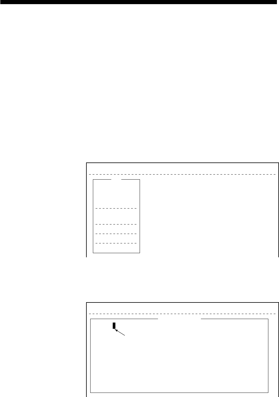
3-1
FILE OPERATIONS
This chapter describes how to prepare, edit, save and print files (mes-
sages).
Preparing a Message
There are two types of files: routine and confidential.
Messages can be assigned a file name and saved to a floppy disk for
later use. A message may contain maximum 124×254 characters (32
Kbytes).
Preparing a routine message
1. Press [F1] to display the File menu.
File Edit Transmit EGC Reports Logs Options Setup Position StopAlarm
File
1. New
2. Open
3. Close
4. Save
5. Delete
6. Rename
7. Print
8. Format Disk
9. MIME (Decode)
ALT-N
ALT-O
ALT-Q
ALT-S
ALT-D
ALT-P
Figure 3-1 File menu
2. Press [1] to select New. The display should now look something
like Figure 3-2.
File Edit Transmit EGC Reports Logs Options Setup Position StopAlarm
Cursor can be a square or an underline.
<[1] UNTITLED1>
0001|t
ASCII
----
*
---------
+
---------
+
---------
+
---------
+
---------
+
---------
+
---------
<
1 Char. [ Line 1/ 1 Col. 1 ] [Insert ]
Figure 3-2 Text editor screen
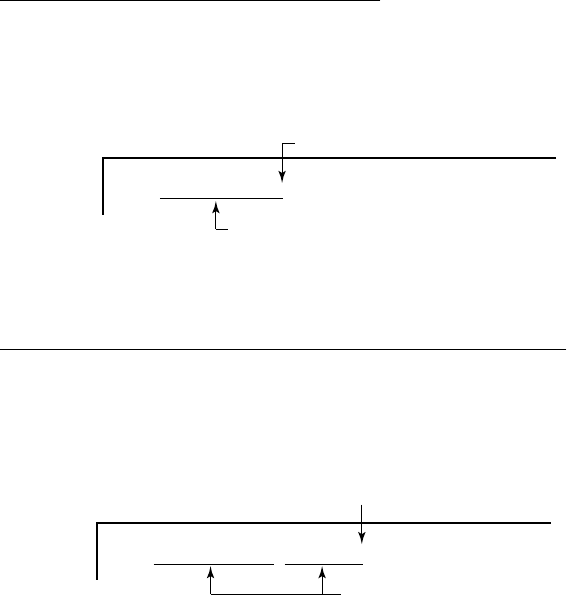
3-2
Note: If the text editor screen does not appear and “close” screen
appears, see “Opening a file where a working area is oc-
cupied” on page 3-11.
3. The cursor is on the first line. Type your message.
Preparing a confidential message
If communicating with another FELCOM 12, you can prepare a con-
fidential message by entering “S???-addressee code(-password):” in
first line of message text. You can also receive confidential messages
containing this header from a land subscriber or any MES which uses
the FELCOM 12.
There are two types of confidential messages: message with addressee
code and message with both addressee code and password.
When a FELCOM 12 receives a confidential message, the message
is not displayed and printed immediately. To display or print the con-
tents of a confidential message, the recipient executes the key se-
quences shown on page 4-23.
Explanation of addressee code and password
Caller and recipient agree beforehand on both the addressee code and
the password. The addressee code can be the title of the recipient; for
example, CAPTAIN. The password could be the classification of the
message; for example, SECRET.
Preparing message with addressee code
Type S, 3 question marks, hyphen, addressee code, colon followed
by text of message.
S???–addressee code: (text of message)
maximum 8 characters
Be sure to enter colon.
Figure 3-3 Addressee code
Preparing message with both addressee code and password
Type S, 3 question marks, hyphen, addressee code, hyphen, pass-
word, colon followed by text of message.
S???–addressee code–password: (text of message)
maximum 8 characters
Be sure to enter colon.
Figure 3-4 Addressee code and password

3-3
When the recipient receives a message with both addressee code and
password, he must enter the password to view contents of the mes-
sage.
Editor menu setup
The Editor menu sets the parameters of the text editor.
1. Press [F8] to display the Setup menu.
2. Press [3] to display the Editor Setup menu.
File Edit Transmit EGC Reports Logs Options Setup Position StopAlarm
Current State: IDLE
DCE Ver **
SYNC ( NCS )
NCS: POR LOGOUT
97-08-07 09:04 (UTC)
LAT: 35:00.00N
LON:135:00.00E
Setup
2. System Setup
3. Editor Setup
4. Terminal Setup
5. EGC Setup
6. Auto Mode Setup
7. E-Mail Setup
8. Directories
9. Configuration
Editor Setup
Text Mode
Edit Mode
Word Wrap
Line No.
Tab Width
Column Width
Cursor Type
Scroll
Ascii
Insert
ON
ON
4 Char
69
Block
Full Screen
Figure 3-5 Editor setup menu
3. Figure 3-5 shows the default editor setup settings. To change set-
tings, select item with arrow keys, press [Enter] to open selection
window, and select settings with arrow keys. After selecting set-
tings, press [Enter].
Text Mode: Select “Telex” or “ASCII”.
Edit Mode: Select “Insert” (insert character at cursor location)
or “Overwrite” (write over character at cursor lo-
cation).
Word Wrap: Turns on/off hyphenation at end of line.
Line No.: Turns line number display on or off.
Tab Width: Sets horizontal tab width; 2, 4 or 8 tabs per line.
Column Width: Select Telex (69 Fixed) or ASCII (40 to 80).
Cursor Type: Selects cursor appearance, either (Block) or un-
derline.

3-4
Scroll: Sets how much the screen moves up over the page
(Full Screen or Half Screen) when [PgUp] or
[PgDn] key is operated.
File Edit Transmit EGC Reports Logs Options Setup Posirion StopAlarm
Cursor can be a square or an underline.
<[1] UNTITLED1>
0001|t
ASCII
----
*
---------
+
---------
+
---------
+
---------
+
---------
+
---------
+
---------
<
1 Char. [ Line 1/ 1 Col. 1 ] [Insert ]
Line Number
Automatic input if turned on line No. in Editor Setup menu.
Figure 3-6 Text editor screen
Cutting and pasting text
1. Place the cursor on the first character of the text to be cut.
2. Highlight the text to be cut by pressing [
/
] while pressing and
holding [Shift]. You can use the right and left arrow keys to adjust
the highlight. The figure below shows the appearance of high-
lighted text.
<[1] UNTITLED1>
ASCII
----
*
---------
+
---------
+
---------
+
---------
+
---------
+
---------
+
---------
<
173 Char. [ Line 2/ 3 Col. 55 ] [Insert ]
0001 WE ARE CONFIDENT THAT YOU WILL ENJOY MANY YEARS OF OPERATION WITH
0002 THIS INMARSAT STANDARD C MOBILE EARTH STATION FELCOM 12
0003 CONGRATULATIONS ON YOUR CHOICE IF FURUNO FELCOM 12t
Figure 3-7 Appearance of highlighted text
3. Press [F2] to select the Edit menu.
Edit
1. Cut
2. Copy
3. Paste
4. Insert (With Citation)
5. Select All
6. Search or Replace
7. Goto Line
8. Time or Pos. Ins
9. Change Window
DEL
ALT-C
INS
ALT-A
ALT-V
Figure 3-8 Edit menu

3-5
4. Press [1] to select Cut. The highlighted text is cut and the remain-
ing text is reformatted. If a mistake is made, you can immediately
restore the text by pressing [Insert].
5. To move text to a new location after it has been cut, place the
cursor at the exact spot in the message where the cut text is to
start. When the text cursor is placed correctly, press [F2] and then
[3] (Paste).
Copying and pasting text
1. Select the text you want to copy.
<[1] UNTITLED1>
ASCII
----
*
---------
+
---------
+
---------
+
---------
+
---------
+
---------
+
---------
<
131 Char. [ Line 2/ 2 Col. 66 ] [Insert ]
0001 THE FURUNO FELCOM 12 INMARSAT STANDARD C MOBILE EARTH STATION, A
0002 SATELLITE COMMUNICATIONS UNIT PACKAGE FOR VIRTUALLY EVERY VESSEL.t
Figure 3-9 Appearance of highlighted text
2. Press [F2] to display the Edit menu.
3. Press [2] to select Copy. The text selected is copied to the internal
clipboard.
4. Place the cursor at the exact spot on the message where the cop-
ied text is to start.
<[1] UNTITLED1>
ASCII
----
*
---------
+
---------
+
---------
+
---------
+
---------
+
---------
+
---------
<
131 Char. [ Line 2/ 2 Col. 66 ] [Insert ]
0001 THE FURUNO FELCOM 12 INMARSAT STANDARD C MOBILE EARTH STATION, A
0002 SATELLITE COMMUNICATIONS UNIT PACKAGE FOR VIRTUALLY EVERY VESSEL.t
0003
Cursor
Figure 3-10 Cursor selects location where to paste text

3-6
5. Press [F2] followed by [3]. The text is placed at the cursor loca-
tion.
<[1] UNTITLED1>
ASCII
----
*
---------
+
---------
+
---------
+
---------
+
---------
+
---------
+
---------
<
137 Char. [ Line 3/ 3 Col. 5 ] [Insert ]
0001 THE FURUNO FELCOM 12 INMARSAT STANDARD C MOBILE EARTH STATION, A
0002 SATELLITE COMMUNICATIONS UNIT PACKAGE FOR VIRTUALLY EVERY VESSEL.
0003 UNITt
Figure 3-11 Text pasted at cursor location
Insert (with Citation)
When you reply to a received message, you can insert the received
message. “>” is placed at the head of the received message to distin-
guish it from your message.
Select All
Selects the entire current file for cut and copy.
Search and Replace
Searches a specified word. Replaces a word with a different word or
character.
Go to line
Moves the cursor to the desired line in the current file.
1. Top of text
2. End of text
3. Go to line: Specify line number
Time or Pos. ins
Inserts time or position in a sentence.
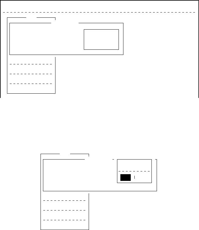
3-7
Saving a Message
Formatting a floppy disk
To save a message to a floppy disk the disk must be formatted. For-
matting prepares the disk no information can be written to its surface.
1. Insert a blank floppy disk into the disk drive.
2. Press [F1].
3. Press [8].
File Edit Transmit EGC Reports Logs Options Setup Position StopAlarm
File
1. New
2. Open
3. Close
4. Save
5. Delete
6. Rename
7. Print
8. Format Disk
9. MIME (Decode)
Format Disk
Insert new disk for drive B:
And select media type
2HD (1.44MB)
2DD (720KB)
Figure 3-12 Format disk screen
4. Select media type.
5. Press [Enter].
File
1. New
2. Open
3. Close
4. Save
5. Delete
6. Rename
7. Print
8. Format Disk
9. MIME (Decode)
Format Disk
Insert new disk for drive B:
And select media type
Start
Yes No
Figure 3-13 FD Format confirmation screen
6. Select “Yes” to format the disk. Press [Enter] to begin formatting.
Note: If there is no floppy disk in the drive, “FD not inserted in
drive. Press any key to escape.” appears on the display.
7. “Now Formatting” appears on the screen during formatting.
8. When formatting is completed (about one minute), “Formatting
Completed.” appears on the display. You can now return to the
standby display by pressing any key.
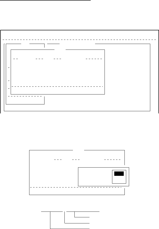
3-8
Saving a message
You can save a message two ways: Save it without losing your place
on the screen (called “save”), or save it before clearing the screen
(called “close”).
Save message, retain place on screen
1. Press [F1] to display the File menu.
2. Press [4]. The screen should look something like Figure 3-14.
File Edit Transmit EGC Reports Logs Options Setup Position StopAlarm
<[1] UNTITLED1>
0001|THE FURUNO FELCOM 12 INMARSAT STANDARD C MOBILE EARTH STATION, A
0002|SATELLITE COMMUNICATIONS UNIT PACKAGE FOR VIRTUALLY EVERY VESSEL.
----
*
---------
+
---------
+
---------
+
---------
+
---------
+
---------
+
---------
<
File
1. New
2. Open
3. Close
4. Save
5. Delete
6. Rename
7. Print
8. Format Disk
9. MIME (Decode)
ALT-N
ALT-O
ALT-Q
ALT-S
ALT-D
ALT-P
Save
[B: ]
To View: SPACE Make Dir: INS Remove Dir: DEL
868
372
6794
864
97-07-15 02:33
97-07-15 02:52
97-07-15 02:59
97-07-15 03:13
Filename Size Date & Time
E0970715.001
E0970715.002
E0970715.003
E0970715.004
4 Files exist 579584 bytes free
Figure 3-14 Save screen
3. Enter a file name, up to eight characters with extension name (three
characters), as shown below.
Save
[B:\SEIZOU ]
To View: SPACE Make Dir: INS Remove Dir: DEL
868
372
6794
864
97-07-15 02:33
97-07-15 02:52
97-07-15 02:59
97-07-15 03:13
Filename Size Date & Time
E0970715.001
E0970715.002
E0970715.003
E0970715.004
4 Files exist 579584 bytes free
OK to save?
No
Yes
Yes
(file name) . (extension name)
3 characters
period
8 characters
Figure 3-15 Configuration of file menu
4. Press [Enter]. “SAVING” appears on display.
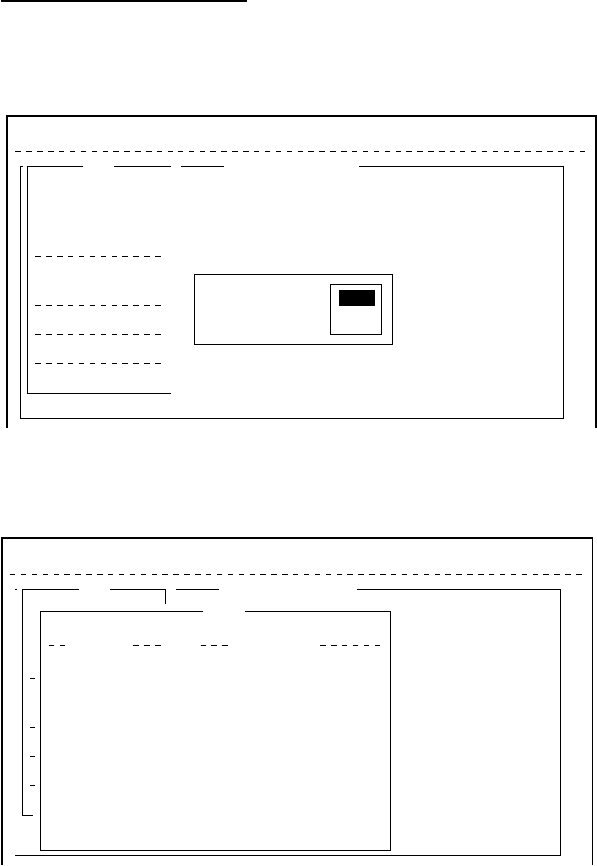
3-9
Save message, clear screen
1. Press [F1] to display the File menu.
2. Press [3]. The prompt “Save this message?” appears on the screen.
File Edit Transmit EGC Reports Logs Options Setup Position StopAlarm
<[1] B:\SEIZOUSE>
NT THAT YOU WILL ENJOY MANY YEARS OF OPERATION WITH
STANDARD C MOBILE EARTH STATION FELCOM 12
S ON YOUR CHOICE IF FURUNO FELCOM 12
t
.
----
*
---------
+
---------
+
---------
+
---------
+
---------
+
---------
+
---------
<
File
1. New
2. Open
3. Close
4. Save
5. Delete
6. Rename
7. Print
8. Format Disk
9. MIME (Decode)
ALT-N
ALT-O
ALT-Q
ALT-S
ALT-D
ALT-P
ASCII 178 Char. [ Line 3/ 3 Col. 52 ] [Insert ]
Save this message?
No
Yes
Figure 3-16 File menu, close file prompt
3. Press [Enter].
File Edit Transmit EGC Reports Logs Options Setup Position StopAlarm
<[1] B:\SEIZOUSE>
NT THAT YOU WILL ENJOY MANY YEARS OF OPERATION WITH
STANDARD C MOBILE EARTH STATION FELCOM 12
S ON YOUR CHOICE IF FURUNO FELCOM 12
t
.
----
*
---------
+
---------
+
---------
+
---------
+
---------
+
---------
+
---------
<
File
1. New
2. Open
3. Close
4. Save
5. Delete
6. Rename
7. Print
8. Format Disk
9. MIME (Decode)
ALT-N
ALT-O
ALT-Q
ALT-S
ALT-D
ALT-P
ASCII [Insert ]
Save
[B:\SEIZOUSE ]
To View: SPACE Make Dir: INS Remove Dir: DEL
901
42
42
868
372
6794
864
1910
97-07-28 20:54
97-07-15 02:13
97-07-14 05:42
97-07-15 02:33
97-07-15 02:52
97-07-15 02:59
97-07-15 03:13
97-07-15 03:48
Filename Size Date & Time
ABC
281 .
COIEKI
.
COMTEST
.
E0970715.001
E0970715.002
E0970715.003
E0970715.004
E0970715.005
74 Files exist 578560 bytes free
Figure 3-17 Save screen
4. Enter a file name.
5. Press [Enter].
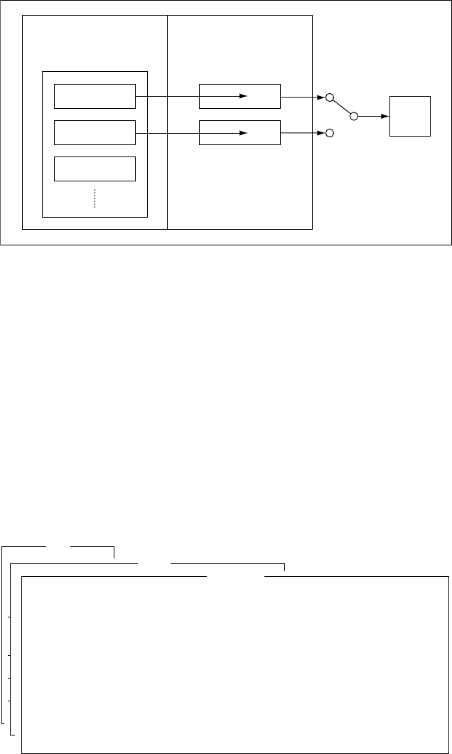
3-10
Opening a File
The internal memory provides two working areas where you can load
one file each. Only one file can be displayed at a time, however you
can easily switch between files.
INTERNAL MEMORY
FLOPPY DISK MEMORY
FILE 1
FILE 2
FILE 3
two WORKING AREAs
1
Display
2
LCD
Can select one
for displaying.
Figure 3-18 Internal memory
Opening a file
1. Set the floppy disk containing the file you wish to open in the
disk drive.
2. Press [F1] to display the File menu.
3. Press [2]. The screen shows a list of the files stored in the floppy
disk.
4. Select a file.
To view a portion of a file, press the space bar.
File
1. New
2. Open
3. Close
4. Save
5. Delete
6. Rename
7. Print
8. Format Disk
9. MIME (Decode)
ALT-N
ALT-O
ALT-Q
ALT-S
ALT-D
ALT-P
Open SEIZOU
THE FURUNO FELCOM 12 INMARSAT STANDARD C MOBILE EARTH STATION, A
SATELLITE COMMUNICATIONS UNIT PACKAGE FOR VIRTUALLY EVERY VESSEL.
UNITt
Figure 3-19 Partial view of a file
5. Press [Enter].
6. The message “Loading” appears on the screen during loading. A
few moments later the contents of the file appear on the screen
and the title bar shows the file name. You may repeat the above
procedure to load a second file into a working area.
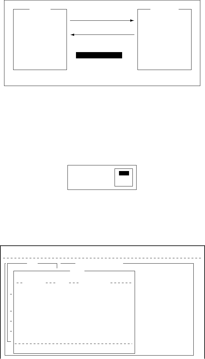
3-11
Switching between files
You can switch between files by selecting Change Window in the
Edit menu. Figure 3-20 illustrates how to switch between files with
Change Window.
1 [F2]
2 9: Change Window
[Enter], or
[ALT] + [V]
How to alternate display of files in working area 1 and 2.
FURUNOABC
Figure 3-20 How the change window feature works
Opening a file where a working area is occupied
When you try to load a file into an occupied working memory, the
display asks you if you want to save the file in that memory before
clearing the display.
Save this message?
No
Yes
Figure 3-21 Prompt for closing a file
To save the file, press [Enter]; select “No” and press [Enter] if you do
not need to save the file. The file screen is erased and then the un-
titled window appears.
File Edit Transmit EGC Reports Logs Options Setup Position StopAlarm
<[1] B:\SEIZOUSE>
NT THAT YOU WILL ENJOY MANY YEARS OF OPERATION WITH
STANDARD C MOBILE EARTH STATION FELCOM 12
S ON YOUR CHOICE IF FURUNO FELCOM 12
t
.
----
*
---------
+
---------
+
---------
+
---------
+
---------
+
---------
+
---------
<
File
1. New
2. Open
3. Close
4. Save
5. Delete
6. Rename
7. Print
8. Format Disk
9. MIME (Decode)
ALT-N
ALT-O
ALT-Q
ALT-S
ALT-D
ALT-P
ASCII [Insert ]
Save
[B:\SEIZOUSE ]
To View: SPACE Make Dir: INS Remove Dir: DEL
901
42
42
868
372
6794
864
1910
97-07-28 20:54
97-07-15 02:13
97-07-14 05:42
97-07-15 02:33
97-07-15 02:52
97-07-15 02:59
97-07-15 03:13
97-07-15 03:48
Filename Size Date & Time
ABC
281 .
COIEKI
.
COMTEST
.
E0970715.001
E0970715.002
E0970715.003
E0970715.004
E0970715.005
74 Files exist 578560 bytes free
Figure 3-22 Save screen
Enter file name followed by [Enter]. The editing screen appears.
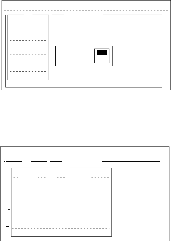
3-12
Saving a File Under a New Name
1. Call up a file.
2. Edit the file.
3. Press [F1].
4. Press [3] (or [4]). “Save this message?” prompt appears. [3] saves
file and closes screen; [4] saves file and keeps position on screen.
File Edit Transmit EGC Reports Logs Options Setup Position StopAlarm
<[1] B:\SEIZOUSE>
NT THAT YOU WILL ENJOY MANY YEARS OF OPERATION WITH
STANDARD C MOBILE EARTH STATION FELCOM 12
S ON YOUR CHOICE IF FURUNO FELCOM 12
t
.
----
*
---------
+
---------
+
---------
+
---------
+
---------
+
---------
+
---------
<
File
1. New
2. Open
3. Close
4. Save
5. Delete
6. Rename
7. Print
8. Format Disk
9. MIME (Decode)
ALT-N
ALT-O
ALT-Q
ALT-S
ALT-D
ALT-P
ASCII 178 Char. [ Line 3/ 3 Col. 52 ] [Insert ]
Save this message?
No
Yes
Yes
Figure 3-23 Save screen, prompt for saving a message before
closing
5. Press [Enter].
6. Press [Backspace] to delete original file name. Enter file name
for new file.
File Edit Transmit EGC Reports Logs Options Setup Position StopAlarm
<[1] B:\SEIZOUSE>
NT THAT YOU WILL ENJOY MANY YEARS OF OPERATION WITH
STANDARD C MOBILE EARTH STATION FELCOM 12
S ON YOUR CHOICE IF FURUNO FELCOM 12
t
.
----
*
---------
+
---------
+
---------
+
---------
+
---------
+
---------
+
---------
<
File
1. New
2. Open
3. Close
4. Save
5. Delete
6. Rename
7. Print
8. Format Disk
9. MIME (Decode)
ALT-N
ALT-O
ALT-Q
ALT-S
ALT-D
ALT-P
ASCII [Insert ]
Save
[B:\SEIZOUSE ]
To View: SPACE Make Dir: INS Remove Dir: DEL
901
42
42
868
372
6794
864
1910
97-07-28 20:54
97-07-15 02:13
97-07-14 05:42
97-07-15 02:33
97-07-15 02:52
97-07-15 02:59
97-07-15 03:13
97-07-15 03:48
Filename Size Date & Time
ABC
281 .
COIEKI
.
COMTEST
.
E0970715.001
E0970715.002
E0970715.003
E0970715.004
E0970715.005
74 Files exist 578560 bytes free
Figure 3-24 Save screen
7. Press [Enter].
Note: Should you decide to save the file under the original name,
skip step 6. The following screen appears.
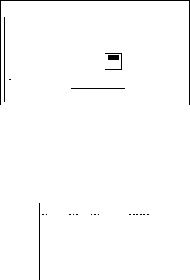
3-13
File Edit Transmit EGC Reports Logs Options Setup Position StopAlarm
<[1] UNTITLED1>
NT THAT YOU WILL ENJOY MANY YEARS OF OPERATION WITH
STANDARD C MOBILE EARTH STATION FELCOM 12
S ON YOUR CHOICE IF FURUNO FELCOM 12
t
.
----
*
---------
+
---------
+
---------
+
---------
+
---------
+
---------
+
---------
<
File
1. New
2. Open
3. Close
4. Save
5. Delete
6. Rename
7. Print
8. Format Disk
9. MIME (Decode)
ALT-N
ALT-O
ALT-Q
ALT-S
ALT-D
ALT-P
ASCII [Insert ]
Save
[B:\SEIZOUSE ]
To View: SPACE Make Dir: INS Remove Dir:DEL
901
42
42
868
372
6794
864
1910
97-07-28 20:54
97-07-15 02:13
97-07-14 05:42
97-07-15 02:33
97-07-15 02:52
97-07-15 02:59
97-07-15 03:13
97-07-15 03:48
Filename Size Date & Time
ABC
281 .
COIEKI
.
COMTEST
.
E0970715.001
E0970715.002
E0970715.003
E0970715.004
E0970715.005
74 Files exist 57850 bytes free
Overwrite?
No
Yes
Yes
Figure 3-25 Save screen, overwrite file name
Printing a File
You can print out a hard copy of a file stored in a floppy disk.
1. Press [F1] to display the File menu.
2. Press [7]. A list of files stored on the disk appears.
P
r
i
nt
[B:\SEIZOU ]
To View: SPACE Make Dir: INS Remove Dir: DEL
412
139
117
836
20
29
128
146
97-07-29 07:21
97-08-07 06:22
97-08-07 06:29
97-07-15 04:53
97-07-17 08:55
97-07-29 10:03
97-07-10 15:02
97-07-11 17:37
Filename Size Date & Time
R0970729.001
SEIZOU .
SEIZOUSE.
T0715 .
T7170 .
TEST .TXT
TESTCAL
.
YANOT
75 Files exist 578560 bytes free
Figure 3-26 Sample print screen
3. Select a file. To get a partial display of the file, tap the space bar.
4. Press [Enter].
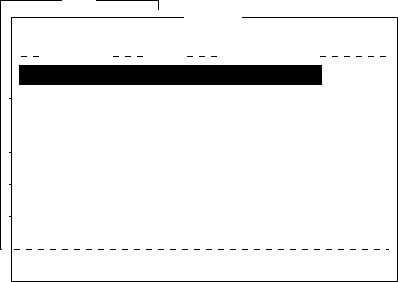
3-14
Combining Files
In the procedure below we’ll combine file A and B.
1. Open file A.
2. Open file B. File B appears on the display.
3. Place the cursor at the beginning of the file. While pressing and
holding down [Shift] press [
/
] to highlight the entire file. (You
can also select a portion of the file.)
4. Press [C] while holding down [Alt]. This places file B on the clip-
board.
5. Press [V] while holding down [Alt]. File B is erased and File A
appears on the display.
6. Press [→] while holding down [Fn] followed by [Enter] to place
the cursor at the end of the file.
7. Press [Insert].
The file B is inserted at the end of the file A.
Deleting a File
1. Press [F1] to display the File menu.
2. Press [5]. A list of files stored on the disk appears.
Fil
e
1. New
2. Open
3. Close
4. Save
5. Delete
6. Rename
7. Print
8. Format Disk
9. MIME (Decode)
ALT-N
ALT-O
ALT-Q
ALT-S
ALT-D
ALT-P
Delete
[B:\ABC28 ]
To View: SPACE Make Dir: INS Remove Dir: DEL
901
901
42
42
868
372
6794
864
97-07-28 20:53
97-07-28 20:54
97-07-15 02:13
97-07-14 05:42
97-07-15 02:33
97-07-15 02:52
97-07-15 02:59
97-07-15 03:13
Filename Size Date & Time
ABC28 .
ABC281 .
COIEKI .
COMTEST
.
E0970715.001
E0970715.002
E0970715.003
E0970715.004
75 Files exist 578560 bytes free
Figure 3-27 Sample delete screen
3. Select the file you want to delete. To verify the contents of that
file, tap the space bar.

3-15
4. Press [Enter]. The prompt “OK to delete file?” appears.
File
1. New
2. Open
3. Close
4. Save
5. Delete
6. Rename
7. Print
8. Format Disk
9. MIME (Decode)
ALT-N
ALT-O
ALT-Q
ALT-S
ALT-D
ALT-P
Delete
[B:\ABC28 ]
To View: SPACE Make Dir: INS Remove Dir: DEL
901
901
42
42
868
372
6794
864
97-07-28 20:53
97-07-28 20:54
97-07-15 02:13
97-07-14 05:42
97-07-15 02:33
97-07-15 02:52
97-07-15 02:59
97-07-15 03:13
Filename Size Date & Time
ABC28 .
ABC281 .
COIEKI .
COMTEST
.
E0970715.001
E0970715.002
E0970715.003
E0970715.004
75 Files exist 578560 bytes free
OK to delete file? Yes
No
Figure 3-28 Prompt for verification of file delete
5. Press [Enter] to delete the file, or press [
/
] and [Enter] to escape.
MIME (Multipurpose Internet Mail Extensions)
When you can't read an attached file in the Log menu, you may de-
code it with MIME as follows:
1. Press [F1].
2. Press [9].
File Edit Transmit EGC Reports Logs Options Setup Position StopAlarm
File
1. New
2. Open
3. Close
4. Save
5. Delete
6. Rename
7. Print
8. Format Disk
9. MIME (Decode)
ALT-N
ALT-O
ALT-Q
ALT-S
ALT-D
ALT-P
Decode
[B:\ ]
To View: SPACE Make Dir: INS Remove Dir: DEL
868
372
6794
864
97-07-15 02:33
97-07-15 02:52
97-07-15 02:59
97-07-15 03:13
Filename Size Date & Time
E0970715.001
E0970715.002
E0970715.003
E0970715.004
4 Files exist 579584 bytes free
Figure 3-29 File, decode
3. Select the file you want to decode.
4. Press [Enter].
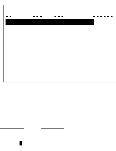
3-16
Rename
Do the following to change file name.
1. Press [F1].
2. Press [6].
File
1. New
2. Open
3. Close
4. Save
5. Delete
6. Rename
7. Print
8. Format Disk
9. MIME (Decode)
ALT-N
ALT-O
ALT-Q
ALT-S
ALT-D
ALT-P
Rename
[B:\ABC28 ]
To View: SPACE Make Dir: INS Remove Dir: DEL
901
901
42
42
868
372
6794
864
97-07-28 20:53
97-07-28 20:54
97-07-15 02:13
97-07-14 05:42
97-07-15 02:33
97-07-15 02:52
97-07-15 02:59
97-07-15 03:13
Filename Size Date & Time
Test .txt
ABC281 .
COIEKI .
COMTEST
.
E0970715.001
E0970715.002
E0970715.003
E0970715.004
75 Files exist 578560 bytes free
Figure 3-30 File, rename
3. Select a file you want to rename.
4. Press [Enter].
Enter new filename
Rename
Test.txt
Figure 3-31 Rename window
5. Delete old file name and then type new file name.
6. Press [Enter].

4-1
INMARSAT-C COMMUNICATIONS
This chapter explains how to transmit and receive in the Inmarsat-C
system.
Before conducting any communications, be sure to login with the
NCS in your area.
To transmit E-mail, register with the LES provider. E-mail charges
are calculated separately.
Transmitting
To transmit a message, you first create the message, attach the ad-
dress of the recipient and send it to the LES. The address of the re-
cipient in the Inmarsat-C system is his telex number for land-line or
MES Inmarsat Mobile Number (IMN) for ship.
The message can be one you’ve just prepared or one stored on a floppy
disk. (Messages cannot be transmitted by means of direct keyboard
input.)
Code description
Code can be specified at the IB-581 or PC.
IA5: International alphabet No. 5, ASCII code (7 bit).
Specify this code to transmit English containing lower case
alphabet.
ITA2: No. 2 international communications alphabet (5 bit).
Specify this code for message which contains only No. 2 in-
ternational communications alphabet (see A-11). ITA2 code
is transmitted faster than IA5 code.
Land-based telex equipment uses ITA2. The LES converts all
codes into ITA2. Code which cannot be converted is shown
with a question mark (?).
DATA: Data (8 bit). Use this code to transmit data.

4-2
Table 4-1 Message, subscriber destination and code
egasseMrebircsbuSepyTnoitanitseDedoCskrameR
hsilgnE.atSCtasramnIXELET5AI
xeleTXELET2ATI
xaFNTSP5AI.XAF03TsiepytmedoM
liam-EliaM-E5AI
naissuR.atSCtasramnINDSPATAD
xeleTXELET2ATI dna)503(EALYPOMREHT
)222(HTAEP
xaFelbaliavatoN
liam-EliaM-EATAD
esenapaJ.atSCtasramnINDSPATAD
xeleTelbaliavatoN
xaFelbaliavatoN
liam-EliaM-EATAD
ataD.atSCtasramnINDSPATAD
krowteNdnaLNDSPATAD
Transmitting prepared message
This section explains routine telex transmission. For distress com-
munication, see page 6-1.
For 2-digit code services and PSTN (FAX) communication, see page
4-17, respectively.
common procedure for transmitting a message
1. Prepare message on the screen.
2. Press [F3] to display the Transmit menu.
25 Char. [ Line 2/ 2 Col. 1 ]
File Edit Transmit EGC Reports Logs Options Setup Position StopAlarm
<[1] UNTITLED1>
0001|t
ASCII
----
*
---------
+
---------
+
---------
+
---------
+
---------
+
---------
+
---------
<
[Insert ]
Transmit
1. Transmit Message
2. Cancel
3. Request Delivery Status
Figure 4-1 Transmit menu

4-3
3. Press [Enter] or [1] to display the Transmit Message menu. The
cursor is on the Priority line and “Normal” is selected.
25 Char. [ Line 2/ 2 Col. 1 ]
File Edit Transmit EGC Reports Logs Options Setup Position StopAlarm
<[1] UNTITLED1>
0001|t
----
*
---------
+
---------
+
---------
+
---------
+
---------
+
---------
+
---------
<
[Insert ]
Transmit
1. Transmit Message
2. Cancel
3. Request Delivery Status
Transmit Message
Priority
Message File
Station Name
Destination Type
Prefix Code
Country/Ocean Code
Station ID
Modem Type
Address
Subject
Attach File
LES ID
Option
[ TRANSMIT ]
Normal
Message now being edited Size 24
TELEX
Figure 4-2 Transmit message menu
Note: An error message may appear under the conditions below:
Unit is not logged-in. -Error message: Cannot start to send.
(not logged-in)
Unit operates as an EGC-only receiver-Error Message:
Cannot start to send. (EGC receiver)
The message file line displays “Message now being edited” when
a file is currently displayed.
4. Press [
/
] three times to place the cursor on the Destination Type
line.
5. Press [Enter] to open the selection window.
6. Select Destination Type among “TELEX”, “FAX” or “SPEC
(Prefixed)”.
25 Char. [ Line 2/ 2 Col. 1 ]
<[1] UNTITLED1>
0001|t
----
*
---------
+
---------
+
---------
+
---------
+
---------
+
---------
+
---------
<
[Insert ]
Transmit
1. Transmit Message
2. Cancel
3. Request Delivery Status
Transmit Message
Priority
Message File
Station Name
Destination Type
Prefix Code
Country/Ocean Code
Station ID
Modem Type
Address
Subject
Attach File
LES ID
Option
[ TRANSMIT ]
Normal
Message now being edited Size 24
TELEX
TELEX
FAX
E-Mail
CSDN
PSDN
X400
DNID
SPEC
TELEX (Prefixed)
FAX (Prefixed)
PSDN (Prefixed)
X400 (Prefixed)
DNID (Prefixed)
SPEC (Prefixed)
Figure 4-3 Transmit message menu, destination type window
7. Press [Enter] to close selection window.

4-4
8. Follow instructions below for TELEX (Prefixed), or go to page4-
5 for FAX or E-Mail.
Destination type: TELEX (Prefixed)
(1) Press [
/
] to place the cursor on the Prefix Code line.
(2) Press [Enter] to open the window for prefix code entry.
(3) Key in prefix code in the digits.
Note that some services may not be available depending on
LES.
edoCxiferPnoitcnuF
11ecnatsissAs'rotarepO
21ediuGlaiD
33ecnatsissAlacinhceT
19tseTxeleTcitamotuA
(4) Press [Enter] to close the window.
(5) Press [
/
] to place the cursor on the Country/Ocean Code
line.
(6) Press [Enter] to open the window for country/ocean code entry.
(7) Type either international telex country code of recipient (ship-
to-shore) or ocean region (ship-to-ship). A list of international
telex country codes begins on page A-1 in the Appendix.
Ocean Region
AOR-East: 581
POR: 582
IOR: 583
AOR-West:584
25 Char. [ Line 2/ 2 Col. 1 ]
<[1] UNTITLED1>
0001|t
----
*
---------
+
---------
+
---------
+
---------
+
---------
+
---------
+
---------
<
[Insert ]
Transmit
1. Transmit Message
2. Cancel
3. Request Delivery Status
Transmit Message
Priority
Message File
Station Name
Destination Type
Prefix Code
Country/Ocean Code
Station ID
Modem Type
Address
Subject
Attach File
LES ID
Option
[ TRANSMIT ]
Normal
Message now being edited Size 24
TELEX
582
Figure 4-4 Transmit message menu, country/ocean code window
(8) Press [Enter] to close the window.

4-5
(9) Press [
/
] to send the cursor to the Station ID line.
(10)Press [Enter] to open the window for station ID entry.
25 Char. [ Line 2/ 2 Col. 1 ]
<[1] UNTITLED1>
0001|t
----
*
---------
+
---------
+
---------
+
---------
+
---------
+
---------
+
---------
<
[Insert ]
Transmit
1. Transmit Message
2. Cancel
3. Request Delivery Status
Transmit Message
Priority
Message File
Station Name
Destination Type
Prefix Code
Country/Ocean Code
Station ID
Modem Type
Address
Subject
Attach File
LES ID
Option
[ TRANSMIT ]
Normal
Message now being edited Size 24
TELEX
Figure 4-5 Transmit message menu, station ID window opened
(11) Type either recipient’s telex subscriber number (ship-to-shore)
or receiving MES INM (ship-to-ship).
(12)Press [Enter] to close the window.
(13)Go to step 9 at the top of page 4-7.
Destination type: FAX
(1) Press [
/
] to advance the cursor to the Modem Type line.
(2) Press [Enter] to open the selection window.
25 Char. [ Line 2/ 2 Col. 1 ]
<[1] UNTITLED1>
0001|t
----
*
---------
+
---------
+
---------
+
---------
+
---------
+
---------
+
---------
<
[Insert ]
Transmit
1. Transmit Message
2. Cancel
3. Request Delivery Status
Transmit Message
Priority
Message File
Station Name
Destination Type
Prefix Code
Country/Ocean Code
Station ID
Modem Type
Address
Subject
Attach File
LES ID
Option
[ TRANSMIT ]
Normal
Message now being edited Size 24
FAX
201 (SANTA PAULA)
Modem Type
T30
V21
V22
V22B
V23
V26B
V26T
V27T
V32
Other
FAX
V.21
V.22
V.22bis
V.23
V.26bis
V.26ter
V.27ter
V.32
300bps Duplex
1200bps Duplex
2400bps Duplex
600/1200bps
2400/1200bps
2400bps Duplex
4800/2400bps
9600bps Duplex
Figure 4-6 Transmit message menu, modem type window opened
(3) Select “T30”.
(4) Press [Enter] to close the selection window.
(5) Go to step 9 at the top of page 4-7.
Destination type: E-mail
(1) Press [
/
] to advance the cursor to the Address line.

4-6
(2) Press [Enter] to open the window for address entry.
25 Char. [ Line 2/ 2 Col. 1 ]
<[1] UNTITLED1>
0001|t
----
*
---------
+
---------
+
---------
+
---------
+
---------
+
---------
+
---------
<
[Insert ]
Transmit
1. Transmit Message
2. Cancel
3. Request Delivery Status
Transmit Message
Priority
Message File
Station Name
Destination Type
Prefix Code
Country/Ocean Code
Station ID
Modem Type
Address
Subject
Attach File
LES ID
Option
[ TRANSMIT ]
Normal
Message now being edited Size 24
E-Mail
INET
201 (SANTA PAULA)
Figure 4-7 Transmit message menu, address window
(3) Type recipient’s E-mail address.
(4) Press [Enter] to close the window.
(5) Press [
/
] to advance the cursor to the Subject line.
(6) Press [Enter] to open the window for subject entry.
25 Char. [ Line 2/ 2 Col. 1 ]
<[1] UNTITLED1>
0001|t
----
*
---------
+
---------
+
---------
+
---------
+
---------
+
---------
+
---------
<
[Insert ]
Transmit
1. Transmit Message
2. Cancel
3. Request Delivery Status
Transmit Message
Priority
Message File
Station Name
Destination Type
Prefix Code
Country/Ocean Code
Station ID
Modem Type
Address
Subject
Attach File
LES ID
Option
[ TRANSMIT ]
Normal
Message now being edited Size 24
E-Mail
INET
201 (SANTA PAULA)
Figure 4-8 Transmit message menu, subject window opened
(7) Type subject.
(8) Press [Enter] to close the window.
(9) Press [
/
] to advance the cursor to the Attach File line.
(10)Press [Enter] to open the select File window.

4-7
25 Char. [ Line 2/ 2 Col. 1 ]
<[1] UNTITLED1>
0001|t
----
*
---------
+
---------
+
---------
+
---------
+
---------
+
---------
+
---------
<
[Insert ]
Transmit
1. Transmit Message
2. Cancel
3. Request Delivery Status
Transmit Message
Priority
Message File
Station Name
Destination Type
Prefix Code
Country/Ocean Code
Station ID
Modem Type
Address
Subject
Attach File
LES ID
Option
[ TRANSMIT ]
Normal
Message now being edited Size 24
E-Mail
201 (SANTA PAULA)
Select File
ENTER: List DEL:
Figure 4-9 Transmit message menu, select file window opened
(11) Press [Enter] to open the file list window.
To change drive on a PC, move the cursor to the command
line, type drive name (for example, “A”), and move the cur-
sor to anywhere in the File Name column.
(12)Press [Enter] to select file and close the file list window.
(13)Press [Esc] to close the select file.
Go to step 9 at the top of the next page.
procedure for transmitting a message (con’t from page 4-5 )
9. Press [
/
] to advance the cursor to the LES ID line.
10. Press [Enter] to open the selection window.
25 Char.
[ Line 2/ 2 Col. 1 ]
<[1] UNTITLED1>
0001|t
[Insert ]
Transmit
1. Transmit Message
2. Cancel
3. Request Delivery Status
Transmit Message
Priority
Message File
Station Name
Destination Type
Prefix Code
Country/Ocean Code
Station ID
Modem Type
Address
Subject
Attach File
LES ID
Option
[ TRANSMIT ]
Normal
Message now being edited Size 24
E-mail
201 (SANTA PAULA)
Name
SANTA PAULA
YAMAGUCHI
KUMSAN
SENTOSA
LES ID
201
202
203
208
210
Remarks
USA
JAPAN
KOREA
SINGAPORE (NCS, ID244)
Figure 4-10 Transmit message menu, LES ID window opened
Note: If the LES ID entered is invalid, “Cannot use this LES.
Please check network configuration.” appears.
11. Select LES ID.
12. Press [Enter] to close the selection window.

4-8
13. Press [
/
] to send the cursor to the Option line.
14. Press [Enter] to open the option window.
<[1] UNTITLED1>
0001|t
Transmit
1. Transmit Message
2. Cancel
3. Request Delivery Status
Transmit Message
Priority
Message File
Station Name
Destination Type
Prefix Code
Country/Ocean Code
Station ID
Modem Type
Address
Subject
Attach File
LES ID
Option
[ TRANSMIT ]
Normal
Message now being edited Size 24
E-mail
201 (SANTA PAULA)
Confirmation
Send Delay
Delivery Delay
Code
ON
00:00
Immediate
IA5
Figure 4-11 Transmit message menu, option window opened
15. Press [Enter] to open the selection window.
16. To receive confirmation from the LES when message has been
delivered to recipient, select ON. If not required, select OFF.
17. Press [Enter] to close the selection window.
18. Press [
/
] to send the cursor to the Send Delay line.
19. Press [Enter] to open the window for send delay entry.
20. To send a message after a certain delay enter a time up to 99 hours
59 minutes.
(The Send Delay is used to time message arrival to suit recipient’s
office hours.)
21. Press [Enter] to close the window.
22. Press [
/
] to go to the Delivery Delay line.
23. Press [Enter] to open the selection window.
24. The Delivery Delay line requests the LES for “Immediate” or
“Deferred” transmission to the recipient designated. Select either
immediate or deferred. For information on this service, consult
with LES to which message is to be sent.
25. Press [Enter] to close the selection window.
26. Press [
/
] to send the cursor to the Code line.
27. Select “IA5”, “ITA2” or “DATA”.
Normally, IA5.
28. Press [Enter] to close the selection window.
29. Press [Esc] to close the option window.
30. Press [
/
] to place the cursor on TRANSMIT.

4-9
31. Press [Enter] to open the start window.
32. Press [Enter] to transmit the message to the message buffer. (To
escape, select No and press [Enter].) The message “Message is
entered in sending Buffer.” appears and the message prepared is
printed.
Note: The message buffer can only hold one message. However a
second message may be sent to the buffer by assigning a
Send Delay to it.
When the message buffer is full, “Cannot enter this mes-
sage to sending Buffer.” appears to alert you.
33. Press any key to return to the standby display.
The message(s) will be transmitted according to Send Delay setting.
“Current State: SENDING” appears at the bottom of the screen dur-
ing transmission.
If the message was transmitted successfully “Successful Sending mes-
sage” appears and its particulars are sent to the Display Log.
TRANSMIT MESSAGE STATUS
The terminal unit displays transmit message status as follows:
“Message Send failed.” This appears if the message could not
be transmitted because of technical reasons such as satellite
malfunction, signal degradation, or no reply from LES. Try to
transmit the message again.
“Message Send rejected.” This appears when the LES rejects
the message because of non-technical reasons such as unpaid
subscriber’s fee.
“Message Send pending.” This appears when the circuits at
the LES are busy. Your message will be transmitted when a
circuit becomes clear.
Transmitting message stored on floppy disk
(multiple address)
1. Close any open files.
2. Insert floppy disk containing file to be sent. (Be sure to insert the
floppy disk completely in the drive. Otherwise, “FD not inserted
in drive.” appears.)
3. Press [F3] to display the Transmit menu.
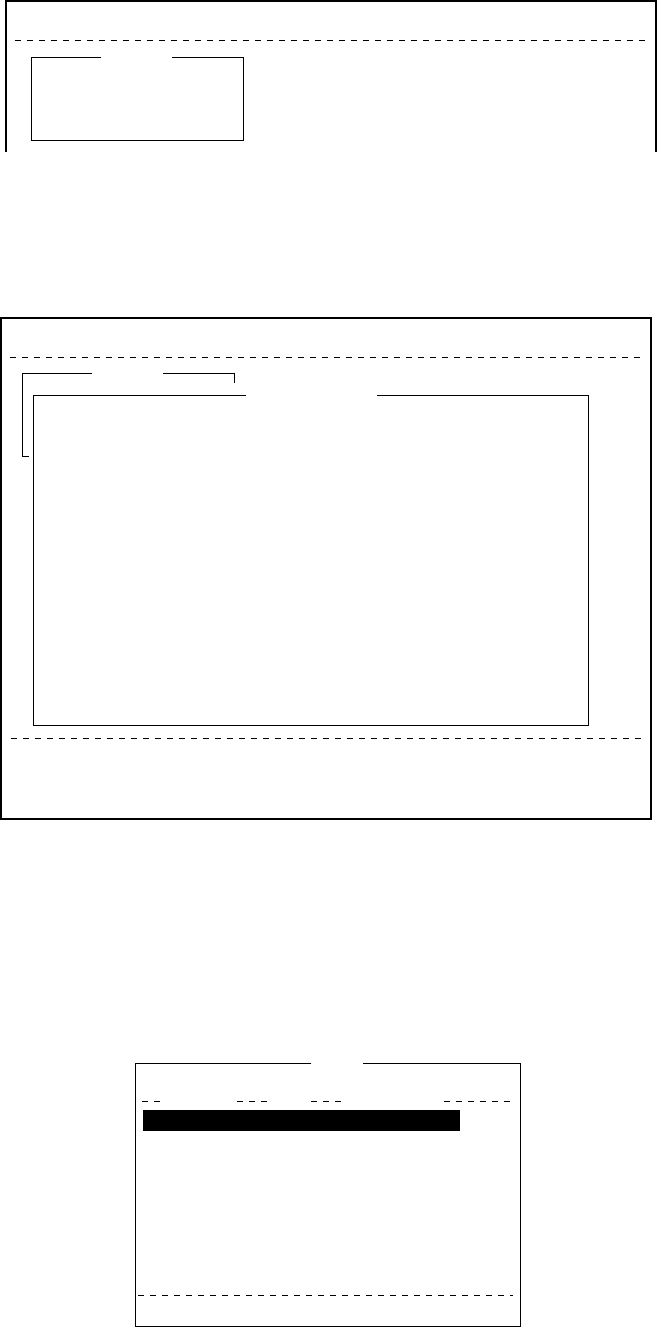
4-10
File Edit Transmit EGC Reports Logs Options Setup Position StopAlarm
Transmit
1. Transmit Message
2. Cancel
3. Request Delivery Status
Figure 4-12 Transmit menu
4. Press [1] to select Transmit Message.
The cursor is on the Priority line and “Normal” is selected.
File Edit Transmit EGC Reports Logs Options Setup Position StopAlarm
Date
Time
Position
Waypoint
Course
Speed
Current NCS
Current Channel
Current TDM
MES Status
GPS Status
DCE Memory
97-08-04
01:32 (UTC)
LAT
LON
LAT
LON
DEG
KTS
344 (IOR) LOGOUT
NCS CC
NCS CC
Idle
****
32818 Bytes free
BBER
C/N
Send level
RxIF AGC Level
REF Offset Freq
Synthe 1st local
3rd local
Synthesizer
TX2nd Local
Antenna Power Supply
Water Temperature
Water Current
Direction
Speed
Depth
003
OK ( 36dB)
OK ( 0)
OK (135)
OK ( 0Hz)
OK
OK
OK
OK
OK
DEG
DEG
KTS
Current State: IDLE
DCE Ver **
SYNC ( NCS )
NCS: IOR LOGOUT
97-08-19 00:26 (UTC)
LAT:
LON:
Transmit
1. Transmit Message
2. Cancel
3. Request Delivery Status
Transmit Message
Priority
Message File
Station Name
Destination Type
Prefix Code
Country/Ocean Code
Station ID
Modem Type
Address
Subject
Attach File
LES ID
Option
[ TRANSMIT ]
Normal
Size 0
TELEX
82
65-2111
303 (YAMAGUCHI)
Figure 4-13 Transmit message menu
5. Press [
/
] to advance the cursor to the Message File line.
6. Enter the file name manually, or select it from the message file list
of the floppy disk as follows.
a) Press [Enter] to display Message File list.
Send
[B:\SEIZOUSE ]
To View: SPACE Make Dir: INS Remove Dir: DEL
Filename Size Date & Time
IIT .
JJJ .
R0970714.001
R0970718.001
R0970729.001
SEIZOU .
SEIZOU .TXT
SEIZOUSE.
70 Files exist 590848 bytes free
9078
13
4973
313
412
139
39
178
97-07-08 19:30
97-07-28 20:57
97-07-14 05:56
97-07-18 00:25
97-07-29 07:21
97-08-07 06:22
97-08-19 21:22
97-08-08 01:44
Figure 4-14 File list

4-11
b) Select a file.
c) Tap the space bar to display a portion of the file in the view
window. Press the [Esc] key.
d) Press [Enter]. The Message File screen appears with the file
selected.
7. Press [
/
] to advance the cursor to the Station Name line.
8. Press [Enter] to open the Station List.
File Edit Transmit EGC Reports logs Options Setup StopAlarm
Date
Time
Position
Waypoint
Course
Speed
Current NCS
Current Channel
Current TDM
MES Status
GPS Status
DCE Memory
97-08-04
01:32 (UTC)
LAT
LON
LAT
LON
DEG
KTS
344 (IOR) LOGOUT
NCS CC
NCS CC
Idle
****
32818 Bytes free
BBER
C/N
Send level
RxIF AGC Level
REF Offset Freq
Synthe 1st local
3rd local
Synthesizer
TX2nd Local
Antenna Power Supply
Water Temperature
Water Current
Direction
Speed
Depth
003
OK ( 36dB)
OK ( 0)
OK (135)
OK ( 0Hz)
OK
OK
OK
OK
OK
DEG
DEG
KTS
Current State: IDLE
DCE Ver **
SYNC ( NCS )
NCS: IOR LOGOUT
97-08-19 00:42 (UTC)
LAT:
LON:
Transmit
1. Transmit Message
2. Cancel
3. Request Delivery Status
Transmit Message
Priority
Message File
Station Name
Destination Type
Country/Ocean Code
Station ID
Modem Type
Address
Subject
Attach File
LES ID
Option
[ TRANSMIT ]
Normal
Size 0
TELEX
82
65-2111
303 (YAMAGUCHI)
ENTER: Station List DEL:
25 Char. [ Line 2/ 2 Col. 1 ] [Insert ]
Station List
Station Name
ENTER: Select SPACE: Mark BS: All Clear
Type Code, ID / Address
321
343199999
TELEX
TELEX
81
583
FURUNO
FRNINMBTSTS
01
02
03
04
05
06
07
08
Figure 4-15 Select station screen
9. Select station and press [Enter].
To select more than one station, press [Space] bar after selecting
station. An asterisk appears next to station(s) selected.
For E-mail, you can select T (TO:Address) or C (CC:Carbon
copy) by pressing [Space] bar.
Note :Different types or prefix code of messages cannot be tranmitted
simultneously.
25 Char. [ Line 2/ 2 Col. 1 ] [Insert ]
Station List
Station Name
01
02
03
04
05
06
07
08
TELEX
TELEX
E-mail
E-Mail
81
583
Seagull@furuno.co.jp
whale@furuno.co.jp
321
343199999
FURUNO
FRNINMBTSTS
Seagull
whale
ENTER: Select SPACE: Mark BS: All Clear
Type Code, ID / Address
*
*
Figure 4-16 With asterisk mark
10. Press [
/
] key to advance the cursor to the LES ID line.
11. Press [Enter] to open the LES Table.

4-12
[Insert ]
Name
YAMAGUCHI
EIK
THERMOPYLAE
ARVI
KUMSAN
LES ID
303
304
305
306
308
Remarks
JAPAN
NORWAY
GREECE (NCS, ID344)
INDIA
KOREA
Figure 4-17 LES list
File Edit Transmit EGC Reports Logs Options Setup Position StopAlarm
Date
Time
Position
Waypoint
Course
Speed
Current NCS
Current Channel
Current TDM
MES Status
GPS Status
DCE Memory
97-08-04
01:32 (UTC)
LAT
LON
LAT
LON
DEG
KTS
344 (IOR) LOGOUT
NCS CC
NCS CC
Idle
****
32818 Bytes free
BBER
C/N
Send level
RxIF AGC Level
REF Offset Freq
Synthe 1st local
3rd local
Synthesizer
TX2nd Local
Antenna Power Supply
Water Temperature
Water Current
Direction
Speed
Depth
003
OK ( 36dB)
OK ( 0)
OK (135)
OK ( 0Hz)
OK
OK
OK
OK
OK
DEG
DEG
KTS
Current State: IDLE
DCE Ver **
SYNC ( NCS )
NCS: IOR LOGOUT
97-08-19 00:26 (UTC)
LAT:
LON:
Transmit
1. Transmit Message
2. Cancel
3. Request Delivery Status
Transmit Message
Priority
Message File
Station Name
Destination Type
Prefix Code
Country/Ocean Code
Station ID
Modem Type
Address
Subject
Attach File
LES ID
Option
[ TRANSMIT ]
Normal
Size 0
TELEX
82
65-2111
303 (YAMAGUCHI)
LES
Name
Perth
Perth
Singapore
LES ID
302
202
210
203
201
Remark
IOR
POR
POR
Figure 4-18 Sample LES table
a) Select LES.
b) Press [Enter].
c) The Transmit Message screen appears with selected LES dis-
played on the LES ID line.
12. Follow steps 13 thru 28 in the previous section.
13. Press [
/
] to place the cursor on TRANSMIT.
14. Press [Enter] twice to transmit the message.
Date
Time
Position
Waypoint
Course
Speed
Current NCS
Current Channel
Current TDM
MES Status
GPS Status
DCE Memory
97-08-04
01:32 (UTC)
LAT
LON
LAT
LON
DEG
KTS
344 (IOR) LOGOUT
NCS CC
NCS CC
Idle
****
32818 Bytes free
BBER
C/N
Send level
RxIF AGC Level
REF Offset Freq
Synthe 1st local
3rd local
Synthesizer
TX2nd Local
Antenna Power Supply
Water Temperature
Water Current
Direction
Speed
Depth
Transmit Message
Priority
Message File
Station Name
Destination Type
Prefix Code
Country/Ocean Code
Station ID
Modem Type
Address
Subject
Attach File
LES ID
Option
[ TRANSMIT ]
Normal
SEISETU.TXT Size 46
FURUNO
TELEX
81
321
303 (YAMAGUCHI) Start
No
Yes
Yes
Figure 4-19 Transmit message menu

4-13
Note: If a file name which was entered manually does not exist
when you attempt to transumit the file at step 13. “Input
Error: Message File” appears. Press any key to erase the
error message then enter correct name.
Canceling transmission
As noted earlier a transmit message is held in the buffer, usually until
it is transmitted satisfactorily. To cancel transmission on a message
held in the buffer, do the following:
1. Press [F3] to display the Transmit menu.
2. Press [2] to display the Cancel screen.
File Edit Transmit EGC Reports Logs Options Setup Position StopAlarm
Current State: IDLE
DCE Ver **
SYNC ( NCS )
NCS: POR LOGIN
97-08-08 07:37 (UTC)
<[1] UNTITLED1>
0001|t
ASCII
----
*
---------
+
---------
+
---------
+
---------
+
---------
+
---------
+
---------
<
25 Char. [ Line 2/ 2 Col. 1 ] [Insert ]
Transmit
1. Transmit Message
2. Cancel
3. Request Delivery Status Cancel
No.
01
Message File
edit_msg.001
Station LES
SANTA PAUL
Priority
Normal
Send Status
Waiting
Delivery
Figure 4-20 Sample cancel screen
Send status
Waiting: Waiting to transmit message.
Sending: Now sending message.
Fail: Failed transmission
Rejected: Message rejected by LES.
Pending: LES circuits occupied.
3. Select message you want to cancel.
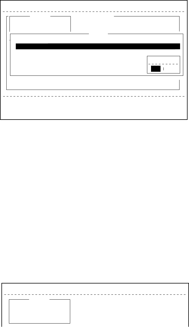
4-14
4. Press [Enter] to open the Cancel window.
File Edit Transmit EGC Reports Logs Options Setup Position StopAlarm
Current State: IDLE
DCE Ver 01
SYNC ( NCS )
NCS: POR LOGOUT
97-08-08 07:38 (UTC)
<[1] UNTITLED1>
0001|t
ASCII
----
*
---------
+
---------
+
---------
+
---------
+
---------
+
---------
+
---------
<
25 Char. [ Line 2/ 2 Col. 1 ] [Insert ]
Transmit
1. Transmit Message
2. Cancel
3. Request Delivery Status
!!!!! Location error !!!!!
Cancel
No.
01
02
Message File
ABC
FELCOM
Station
FURUNO
FUSA
LES
Perth
SANTAPAULA
Priority
Normal
Normal
Send Status
Waiting
Sending
Delivery
Cancel
NoYes
Figure 4-21 Cancel window
5. Press [Enter] to cancel a message from transmission, or select
“No” and press [ Enter] to escape from the Cancel menu.
6. Press [Esc] to return to the default display.
Confirming delivery status (message status list)
You can automatically receive delivery status of messages you send
to a LES, by selecting “Confirming ON” in the Send Message menu.
(Delivery Status can also be confirmed manually. See page 4-16.)
Messages transmitted which request delivery status appears in the
Message Status List.
The Message Status List holds delivery status information for 30 mes-
sages. When the list is full, the oldest entry is deleted to make room
for the latest.
1. Press [F3].
File Edit Transmit EGC Reports Logs Options Setup Position StopAlarm
Transmit
1. Transmit Message
2. Cancel
3. Request Delivery Status
Figure 4-22 Transmit menu

4-15
2. Press [3] to display the Request Delivery Status menu.
Request Delivery Status
No.
01
02
03
04
05
06
07
Message File
ABC
DEF
GHI
JKL
MNO
edit msg.002
edit msg.001
Station
FURUNO
FURUNO
ASDFASDF
ABCDEFGHIJ
LES
Yamaguchi
Yamaguchi
202
303
123
202
Yamaguchi
Priority
Normal
Normal
Normal
Normal
Normal
Normal
Normal
Send Status
Waiting
Sending
97-03-20 9:40
97-03-18 20:16
97-03-18 16:09
97-03-18 9:48
97-03-16 12:34
Delivery
OCC(002)
Complete
EEE(001)
?????
Figure 4-23 Sample request delivery states
Message status list description
No.: Message number
Message File: File name. For no file name, “edit msg. 00X” appears
(X = number from 001-999).
Station: Name of remote party (recipient)
LES: The LES which received the message.
Priority: Normal or distress
Send Status: The transmission status from the MES (own ship) to
the LES; waiting or sending, and data and time of
transmission for messages transmitted.
Delivery: The delivery status from the LES to the recipient.
Complete: Message transmitted successfully
White space: Delivery status not yet received
Reason for no delivery:
OCC(002): Delivery tried (twice), but recipient busy.
ABS: Absent subscriber
BK: Message aborted
BMC: No end of message or end of transmission received
DER: Out of Order
DTE: Remote DTE clearing
EOS: Element of Service not subscribed (E-mail)
FMT: Format error
IAB: Invalid answerback
INC: Inconsistent Request (E-mail)
INF: Call the Network Information service
INV: Invalid Call
ITD: Awaiting delivery
LDE: Maximum message length exceeded
LPE: Local Procedure Error
NA: Access Barred
NC: Network Congestion
NCH: Subscriber’s number has been changed
NP: Not Obtainable
NRC: Reverse charging acceptance not subscribed
RIS: Recipient Improperly Specified (E-mail)
RDI: Redirected call
RPE: Remote Procedure Error

4-16
RSB: Retransmission still being attempted
TMD: Maximum number of addresses exceeded
UNK: Unknown status (for example when the Logical
channel number is zero)
Note: Some LES do not use certain codes.
Manually requesting delivery status
You can request a LES for delivery status of a message you have
transmitted there within the past 24 hours.
1. Press [F3].
2. Press [3] to display the Request Delivery Status display.
Request Delivery Status
No.
01
02
Message File
ABC
edit msg.002
Station
FURUNO
FURUNO
LES
Perth
Perth
Priority
Normal
Normal
Send Status
97-11-06 16:10
Delivery
Figure 4-24 Request delivery status display
3. Select a file.
4. Press [Enter]. A prompt asks you if you want to request delivery
status on that message.
Request Delivery Status
No.
01
02
Message File
ABC
edit msg.002
Station
FURUNO
FURUNO
LES
Perth
Perth
Priority
Normal
Normal
Send Status
97-11-06 16:10
Delivery
Start
No
Yes
Figure 4-25 Sample message file list
5. Press [Enter] to request status. “Request started” appears on the
display. (To cancel request, select “No” and press [Enter].)
6. “Press any key.” appears on the display; press any key to return to
the standby display.
Several minutes later the reply from the LES appears in the Delivery
column of the Request Delivery Status screen.

4-17
The 2-digit code services
A range of special safety and general maritime services, known as
the 2-digit code services, may be received. The list on the next page
shows the 2-digit code services available.
To access a 2-digit code service;
1. Using the text editor, prepare message requesting a 2-digit code
service. (Refer to next page.)
2. Press [F3] to display the Transmit menu.
3. Press [Enter] to display the Transmit Message.
25 Char. [ Line 2/ 2 Col. 1 ]
File Edit Transmit EGC Reports Logs Options Setup Position StopAlarm
<[1] UNTITLED1>
0001|t
----
*
---------
+
---------
+
---------
+
---------
+
---------
+
---------
+
---------
<
[Insert ]
Transmit
1. Transmit Message
2. Cancel
3. Request Delivery Status
Transmit Message
Priority
Message File
Station Name
Destination Type
Prefix Code
Country/Ocean Code
Station ID
Modem Type
Address
Subject
Attach File
LES ID
Option
[ TRANSMIT ]
Normal
Message now being edited Size 24
TELEX
Figure 4-26 Transmit message menu
4. Press [
/
] three times to place the cursor on the Destination Type
line.
5. Press [Enter] to open the selection window.
6. Select “SPEC” (Special).
7. Press [Enter] to close the selection window.
8. Press [
/
] to place the cursor on the Station ID line.
9. Press [Enter] to open the window for station ID entry.
10. Key in 2-digit code referring to the tables on the next page.
11. Press [Enter] to close the window.

4-18
For maritime safety service;
32 Medical advice Used for requesting medical advice.
38 Medical assistance Used for requesting medical assistance.
39 Maritime assistance Used for requesting maritime search and rescue
assistance.
41 Meteorological reports Necessary for ease of addressing weather reports from
ships to meteorological centers.
42 Navigational Hazards and
warnings
Used for making urgent navigational meteorological
danger reports.
43 Ship position reports Used for routing of messages to ship safety reporting
systems.
For general utility;
31 Maritime enquiries Desirable for requesting information including service
offerings.
33 Technical assistance Desirable for addressing technical enquiries to
appropriate personnel.
37 Time and charges requested at
end of call
Desirable for mobile operator when sending traffic for a
third party.
12. Press [
/
] to advance the cursor to the LES ID line.
13. Press [Enter] to open the LES table.
14. Press [Enter] to select LES ID.
15. Press [
/
] to place the cursor on TRANSMIT.
16. Press [Enter]. A prompt asks if it is alright to start transmission.
(The Confirmation, Send Delay and Delivery Delay remain “ON”,
“00:00” and “Immediate”, respectively. If necessary, change these
settings before pressing [Enter].)
17. Press [Enter] to transmit the message prepared.
18. Press any key to return to the standby display.
The message will be transmitted according to Send Delay setting.
“Current State: SENDING” appears at the bottom of the screen
during transmission.
If the message was transmitted successfully “Successful Sending
message” appears and its particulars are sent to the Display Log.
Note 1: At present, not all LESs are offering the 2-digit code ser-
vices. To find out which LESs are offering the services, con-
tact the LES Operations Coordinator directly.
Note 2: Some 2-digit code services may be provided free of charge by
LESs, while other services are chargeable, in some cases at
reduced rates. For information, contact the LES directly.

4-19
Inserting the destinations of a fax terminal
You can send a text message to a Group 3 type fax terminal which is
connected to the international PSTN (telephone) land line, provided
the LES selected supports fax delivery.
1. Prepare message. (To send stored file, close any open files.)
2. Press [F3] to display the Transmit menu.
3. Press [1] to select Transmit Message.
The cursor is on the Priority line and “Normal” is selected.
4. Press [
/
] to advance the cursor to the Message file line.
5. The message file line displays “Message now begin edited.” when
a file is the currently displayed. To send a file stored on a floppy
disk, select the file from the file list.
6. Press [
/
] to advance the cursor to the Destination Type line.
7. Press [Enter] to open the selection window.
8. Select “FAX”.
9. Press [Enter] to close the selection window.
25 Char. [ Line 2/ 2 Col. 1 ]
0001|t
[Insert ]
Transmit Message
Priority
Message File
Station Name
Destination Type
Prefix Code
Country/Ocean Code
Station ID
Modem Type
Address
Subject
Attach File
LES ID
Option
[ TRANSMIT ]
Normal
Message now being edited Size 77
FAX
Figure 4-27 Transmit message menu, FAX selected
10. Press [
/
] to advance the cursor. The cursor is now on the Coun-
try/Ocean Code line.
11. Press [Enter] to open the window for country/ocean code entry.
12. Key in international telephone code of recipient. A list of interna-
tional telex/telephone country codes begins on page A-1 in the
Appendix.
13. Press [Enter] to close the window.
14. Press [
/
] to send the cursor to the Station ID line.
15. Press [Enter] to open the window for station ID entry.
16. Enter facsimile number.

4-20
17. Press [Enter] to close the window.
18. Press [
/
] to send the cursor to the Modem Type line.
19. Press [Enter] to display the list of modem types.
20. Press [Enter] to select “T30”. (Other modem types are not sup-
ported.)
21. Press [
/
] to advance the cursor to the LES ID line.
22. Press [Enter] to open the LES Table.
23. Select LES ID.
Note: If the LES ID entered is invalid, “Cannot use this LES.
Please check network configuration.” appears.
24. Press [Enter] to close the LES Table.
25. Press [
/
] twice to place the cursor on TRANSMIT.
26. Press [Enter] twice to send the message to the message buffer.
(To escape, select No and press [Enter].) The message “Message
is entered in sending Buffer.” appears.
At the same time, the message prepared is printed.
27. Press any key to return to the standby display.
The message(s) will be transmitted according to the Send Delay set-
ting. “Current State: SENDING” appears at the bottom of the screen
during transmission.
When the message is transmitted successfully “Successful Sending
message” appears and its particulars are sent to the Display Log.
Receiving
When a message is received
Each time the FELCOM 12 receives a message it automatically reg-
isters, saves, prints (except messages with passwords) and files it.
1) received alarm
When a message is received, the audible alarm sounds.
Silence the audible alarm by pressing the [F10] key on the keyboard.
2) registration
Each message received is assigned a receive message number. This
number is also used when the file is saved to a floppy disk.
R
Receive
0
0: main DTE
1: 2nd DTE
9 7
year
0 1
month
1 5.
day
0 0 1
receive
message no.

4-21
3) display log
The Display Log shows message number, priority, date and time of
transmission, LES ID and file size (in bytes) of the latest 50 received
and transmitted messages.
4) printing
Printing of a message begins (except messages with passwords) as
soon as it is received.
5) saving and filing
The DTE saves and files a receive message to the Display Message
List. (For installations with both a main and a 2nd DTE, you may
select where to store receive messages, on the system setup menu.)
The Display Message List shows the following:
Receive message no.
LES ID
Priority
File size (in bytes)
Message classification
Password for confidential messages
Date and time of transmission
Status
Setting the receive alarm
An audible alarm may be set to ring when a routine message is re-
ceived. The factory setting is OFF.
1. Press [F8] to display the Setup menu.
2. Press [6] to display the Auto Mode Setup.
Setup
7. E-Mail Setup
8. Directories
9. Configuration
Auto Mode Setup
OFF
ON
ON
OFF
ON
Auto Log Print
Receive Alarm
Auto Telex Msg Save
Auto EGC Msg Save
Data Report & Polling Print
Figure 4-28 Auto mode setup menu
3. Press [
/
] to send the cursor to the Receive Alarm line.
4. Press [Enter] to open the selection window.
5. To enable the alarm, select ON. The alarm will be released for
one second when a message is received.
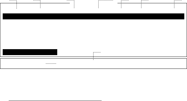
4-22
6. Press [Enter] to close the selection window.
7. Press [Esc] twice.
Displaying receive messages
When you can't read an attached file in Log menu refer to page
3-15.
1. Press [F6].
2. Press [2] to display list of receive messages.
Received Message Log
Message No.
R0971106.001
R0971105.002
R0971105.001
R0971024.001
Space: display part view
LES
Perth
ABCDEFGHIJ
Perth
Perth
Priority
Normal
Normal
Distress
Normal
Addressee
CAPTAIN
Rec date & Time
97-11-06 16:10
97-11-05 17:30
97-11-05 14:15
97-10-24 13:20
Status
Saved
Printed
Saved
Memory Available: 12345 Bytes
Size
32767
200
1234
8251
(Part View Window)
12
9
3 4 5
8
6 7
Figure 4-29 Sample display message screen
Display message list description
Message No.: Receive message no.
LES: LES name
Priority: Normal or distress
Size: Size of file in bytes
Addressee: Addressee code appears for confidential mes-
sages. Nothing appears for routine messages.
Rec date & time: Date and time message was received.
Status: Printed: message printed
Saved: message saved to floppy disk
No display: not yet printed confidential mes-
sage, or printer malfunction
Memory available: Memory available in DTE
3. Select a file. To get a partial display of a file selected, tap the
space bar. A part of the file appears in the View Window.

4-23
4. Press [Enter] for routine messages and messages with addressee
code (no password).
Your selection appears on the display.
Display Receive Message <R0971123.002->
FROM FURUNO
TO FRONTIER
THE QUICK BROWN FOX JUMPS OVER LAZY DOG.
ABCDEFGHIJKLMNOPQRSTUVWXYZ. 1234567890
Ctrl+P: print
Figure 4-30 Sample receive message
5. For messages with both addressee code and password, a Pass-
word window appears. Enter the password corresponding to the
addressee code and then press [Enter]. If the password is entered
incorrectly an alarm sounds. Reenter the password.
Display Message
Message No.
R0971106.001
R0971105.002
R0971105.001
R0971024.001
LES
Perth
ABCDEFGHIJ
Perth
Perth
Priority
Normal
Normal
Distress
Normal
Addressee
CAPTAIN
Rec date & Time
97-11-06 16:10
97-11-05 17:30
97-11-05 14:15
97-10-24 13:20
Status
Saved
Printed
Saved
Memory Available: 12345 Bytes
Confidential Message
Size
32767
200
1234
8251
PASS WORD: _ _ _ _ _ _
Figure 4-31 Location of password
The screen can be scrolled with the up and down arrow keys.
Printing receive messages
1. Follow steps 1 thru 6 in “Displaying receive messages”.
2. While pressing and holding down [Ctrl], press [P]. The printer
starts printing the message on the screen.
Receive Message (SECRET)
Message No.
Message Ref. No.
LES
Priority
Message Size
Receive Date & Time
abcdefghijklmnopqrstuvwxyz........
: R0970323.001
: 00000000
: LES or LES ID
: Normal (or Distress)
: 205 characters
: 97-03-23
Appears only for confidential messages
Text
Figure 4-32 Sample receive message printout

4-24
Saving receive messages to a floppy disk
1. Press [F6].
2. Press [2] to display the Receive Message Log.
Receive Message Log
Message No.
R0971106.001
R0971105.002
R0971105.001
R0971101.001
R0971024.001
LES
Perth
ABCDEFGHIJ
Perth
Perth
Perth
Priority
Normal
Normal
Distress
Normal
Normal
Addressee
CAPTAIN
OFFICER
Rec date & Time
97-11-06 16:10
97-11-05 17:30
97-11-05 14:15
97-11-01 3:45
97-10-24 13:20
Status
Saved
Printed
Printed
Printed
Saved
Memory Available: 3317 Bytes
Size
32767
200
1234
3256
8251
Enter: Display S: Save D: Delete
Figure 4-33 Sample delete message screen
3. Select a file. Press the [Enter] key to confirm contents of file.
After confirming contents, press the [Esc] key.
4. For confidential messages enter password. This password will also
be saved to the floppy disk.
5. Press the [S] key to save the file to the floppy disk.
Note: If a file by that name already exists on the floppy disk,
“A file by that name already exists on FD.” appears.
Automatically saving receive messages
1. Press [F8].
2. Press [6] to display Auto Mode Setup menu.
Setup
7. E-Mail Setup
8. Directories
9. Configuration
Auto Mode Setup
OFF
ON
ON
OFF
ON
Auto Log Print
Receive Alarm
Auto Telex Msg Save
Auto EGC Msg Save
Data Report & Polling Print
Figure 4-34 Auto mode setup menu
3. Press [
/
] to select “Auto Telex MSG Save”.
4. Press [Enter] to open the selection window.
5. Select “ON”.
6. Press [Enter] to close the selection window.
7. Press [Esc] twice.

4-25
The drive and directory where to save receive messages and created
files can be specified with “MSG Directory”. The default setting is as
follows;
For IB-581 B:\
For PC “MAIL” directory in directory which stores program
files
Note: For IB-581 do not specify the ROM disk (drive A) as the “MSG
directory.” The ROM disk can only be written to 1000 times.
Receive messages are automatically assigned a file name as described
on page 4-20.
EGC messages can also be automatically saved. EGC messages are
automatically assigned a file name and they begin with E.
Deleting receive messages
1. Press [F6].
2. Press [2] to display list of receive messages.
Delete Message
Message No.
R0971106.001
R0971105.002
R0971105.001
R0971101.001
R0971024.001
LES
Perth
ABCDEFGHIJ
Perth
Perth
Perth
Priority
Normal
Normal
Distress
Normal
Normal
Addressee
CAPTAIN
OFFICER
Rec date & Time
97-11-06 16:10
97-11-05 17:30
97-11-05 14:15
97-11-01 3:45
97-10-24 13:20
Status
Saved
Printed
Printed
Printed
Saved
Memory Available: 3317 Bytes
Size
32767
200
1234
3256
8251
(Part View Window)
Figure 4-35 Sample delete message screen
3. Select the message you want to delete. To display a part of a mes-
sage (except confidential messages), tap the space bar.
4. To view a portion of a confidential file, enter the password and
then tap the space bar.
5. Press [D]. You are asked to confirm.
6. Press [Enter] to delete the message, or select No and press [Enter]
to escape.
7. To return to the standby display, press [Esc] three times.
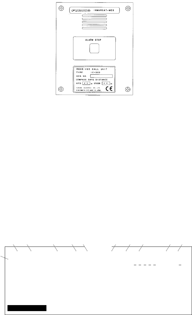
4-26
Distress/Urgent Receiving Call Unit IC-303
The IC-303 releases an audio alarm when a distress or urgency prior-
ity EGC message is received. Press the ALARM RESET button to
acknowledge the alarm, and the tone of alarm changes. To silence the
alarm, press the [F10] key on the keyboard of terminal unit.
Figure 4-36 Distress/Urgent Receiving Call Unit IC-303
Display Log
The Display Log stores the particulars of the latest 50 received and
transmitted messages. When the log is full, the oldest message is de-
leted.
Displaying and printing the display log
1. Press [F6].
2. Press [4] to display the Display Log.
Display Log
S/R
S
R
Message No.
T0971110.001
R0971110.001
Type
TELEX
TELEX
PSTN
PSDN
E-mail
(etc.)
Pri
Nrm
Dis
Date
97-11-10
97-11-10
Time
19:10
19:25
LES
302
302
Station
FURUNO
Cond
Success
Fail
Size
12345
365
01
02
50 (max)
Ctrl+P: print
.
.
.
1
23 4 5 6 7 8 9 !0 !1
Figure 4-37 Sample display log
3. To scroll the Display Log screen, press the down key several times.
4. To print the log, press and hold down [Ctrl] and press [P].
“Now printing” appears on the screen.

4-27
display log description
S/R: Send or Receive message
Message No.: Message no. or file name
Type: Currently, TELEX, PSTN, PSDN or SPEC
(2-digit code service).
Pri: Normal or distress
Date: Date message was received (or transmitted).
Time: Time message was received (or transmitted).
LES: ID of LES which handled the message
Station: Transmitting station name. Blank for unreg
istered station or receive message.
Size: Size of message in bytes
Cond: Transmission results. Blank if receive
message.
Success: Successful transmission
Fail: Failed transmission
Rejected: Message rejected by LES
Automatic printing of display log
The Display Log can be automatically printed every 24 hours.
1. Press [F8] to display the Setup menu.
2. Press [6] to display the Auto Mode Setup menu.
Setup
7. E-Mail Setup
8. Directories
9. Configuration
Auto Mode Setup
OFF
ON
ON
OFF
ON
Auto Log Print
Receive Alarm
Auto Telex Msg Save
Auto EGC Msg Save
Data Report & Polling Print
Figure 4-38 Auto mode setup menu
3. Press [Enter] to open the selection window of Auto Log Print.
4. Set Auto Log Print to ON.
5. Press [Enter] to close the selection window.
6. Press [Esc] twice.

4-28
Display send message log or receive message log
You can display send message log or receive message log as follow.
1. Press [F6].
2. Press [1] (Send message log) or [2] (Receive message log).
3. Press [Esc] to escape.
EGC Messages
EGC messages are automatically received, printed and saved to the
DTE. The memory capacity for EGC message is 32k bytes. When the
memory is full, the oldest information is deleted.
Displaying and reprinting EGC messages
1. Press [F6].
2. Press [3]. The Display EGC Message screen appears.
File Edit Transmit EGC Reports logs Options Setup StopAlarm
Current State: IDLE
DCE Ver **
SYNC ( NCS )
NCS: IOR LOGIN
97-08-19 07:15 (UTC)
LAT: 35:00.00N
LON: 135:00.00E
Display EGC Message
EGC Message --- MET Navarea Warning or MET Forecast ---
Message Sequence No.
LES
Priority
Size
Receive Date & Time
ZCZC
NAVAREA XI WARNING
NAVAREA XI 0480.
NORTH PACIFIC, WESTERN PART.
DISTRESS SIGNALS ON 243MHZ AND
121.5 MHZ RECEIVED IN
29-40.4N 174-15.0E.
Ctrl+P: Print P: Previous N: Next
: 00472
: YAMAGUCHI
: Urgent
: 285 characters
: 97-08-19 06:08 (UTC)
Figure 4-39 Sample Display EGC Message screen
3. To scroll the message, use the up and down arrow keys.
4. To view next and previous messages, use the [N] and [P] keys.
5. To print the message appearing on the display, press and hold
down [Ctrl] and press [P]. To stop printing, press [Esc].
EGC messages can be automatically saved on a floppy disk. See page
4-24 for details.

4-29
Displaying EGC closed network ID (ENID)
To join a FleetNETTM service, an MES must be registered with an
information provider. The information provider adds the MES to the
group which is to receive the service by downloading a Group Call
ID, via a LES which supports FleetNETTM broadcasts, uniquely ad-
dressed to the MES. The MES stores the ID and can accept broad-
casts from the information provider. The MES operator can not change
this stored EGC closed network IDs (ENIDs). Up to 64 ENIDs are
stored on a non-volatile memory.
The ENID stored can be accessed for downloading and deleting via
the satellite path. It is possible for an MES operator to inhibit (or
activate as required), via the DTE, selected ENIDs previously down-
loaded.
Along with the ENID, the name of the information provider is stored.
In the event that a download command is received and the ENID
storage area is full, then an ENID which has been inhibited (de-acti-
vated) by the MES operator will be written over. If none has been
inhibited, then the new download is not accepted.
Follow the procedure below to inhibit (or activate) an ENID.
1. Press [F4] to display EGC menu.
2. Press [2] to display the EGC Network ID List.
File Edit Transmit EGC Reports Logs Options Setup Position StopAlarm
SYNC ( NCS )
NCS: IOR LOGIN
97-02-28 12:00 (UTC)
LAT: 34:43.00N
LON: 135:21.00E
1. Display EGC Message
2. EGC Network ID
EGC
ENT: Activate SPACE: Inhibit Ctrl+P: Print ESC: Quit
Mark ‘*’ means activation
01
02
03
04
05
06
07
08
*
*
*
*
*
*
*
*
00001
00002
04001
04002
04003
04005
04006
04007
202
202
202
202
202
202
202
202
FURUNO
FURUNO
FURUNO
FURUNO
FURUNO
FURUNO
FURUNO
FURUNO
EGC Network ID List
Current State: IDLE
DCE Ver **
Figure 4-40 EGC network ID list

4-30
3. Select an ENID you want inhibit (or activate).
4. Press the Space bar to inhibit (or [Enter] key to reactivate).
5. Press [Esc] to return to the standby display.
Receiving EGC distress or urgent message
When the FELCOM 12 receives a EGC distress or an urgent mes-
sage, an alarm buzzer sounds on the terminal unit and the Distress/
Urgent Receiving Unit IC-303 or the Distress Message Controller
DMC-5 when connected.
To silence the alarm buzzer, press [F10] on the terminal unit.
Note: To silence the alarm from the IC-302, also press [F10]. DO
NOT press the DISTRESS button on the IC-302 to silence the
alarm; you will transmit own ship’s distress alert.
Tx Message Example Printout
The Tx message printout changes according to whether "Confirma-
tion" (keying sequence: [F3], [1], "Option") on thetransmit message
is ON or OFF.
Confirmation "OFF"
A TX message is printed when the message result is "Success".
Sent Message
DELIVERY CONFIRMATION OFF
Message File : 00FOX.TXT Message Size : 277 characters
LES : GOONHILLY Date : 99-03-10
Priority : Normal Time : 06:06 (UTC)
Destination : TELEX (Prefixed) 00111222222222222222 (IA5)
00111333333333333333
00111444444444444444
Figure 4-41 TX message printout when Confirmation is OFF

4-31
Confirmation "ON"
The message "Delivery Status received for (file name)" is displayed
when you received message delivery data and the message is printed.
Note: After the message "Delivery Status received for" appears, wait
more than two minutes before sending another message. If you at-
tempt to transmit before two minutes has elapsed the the message
and delivery information will be printed again.
Sent Message
DELIVERY CONFIRMED
Message File : 00FOX.TXT Message Size : 277 characters
LES : GOONHILLY Date : 99-03-10
Priority : Normal Time : 06:06 (UTC)
Destination : TELEX (Prefixed) 00111222222222222222 (IA5)
Figure 4-42 Tx message printout when Confirmation is ON
(delivery confirmed)
Sent Message but not delivered
DELIVERY FAILURE : xxx (xxx = reason for no delivery)
DELIVERY STATUS NOT RECEIVED (in case of timeout)
Message File : 00FOX.TXT Message Size : 277 characters
LES : GOONHILLY Date : 99-03-10
Priority : Normal Time : 06:06 (UTC)
Destination : TELEX (Prefixed) 00111222222222222222 (IA5)
Figure 4-43 Tx message printout when Confirmation is ON (message
not delivered)
4-32
(This page intentionally left blank.)

5-1
DATA REPORTING AND POLLING
This chapter explains data reporting settings and polling reception.
Data reporting provides automatic data transmission at regular
intervals from your ship to your home office, when your ship
receives a polling command from your home office, it automati-
cally transmits data to your home office.
No operator intervention is required during polling reception.
Data Reporting
Data reporting provides automatic data transmission at regular (pre-
set) intervals from your ship to your home office. The data are posi-
tion, speed, bearing and other data sent from a navigational equipment
or an interface unit.
The data transmitted from the FELCOM 12 is temporarily stored in a
data reporting file at the LES. When an operator at your home office
accesses the LES, the LES delivers the data to your home office.
Some LESs may deliver it without being accessed.
Data reporting can be initiated by setting a data report on the FELCOM
12 or receiving a polling command from your home office.
FELCOM 12 offers two types of data reporting as follows:
¡Data report ---------on MES signalling channel
Refer to “Setting a data report” below.
¡Message report --- on MES message channel
Refer to “Setting a message report” on page 5-4.
Setting a data report
1. Press [F5] to display the Position Reports menu.
Position Reports
1. Data Report
2. Message Report
3. Data Network ID
Figure 5-1 Position reports menu
Data report
Message report Polling
Satellite
Mobile Earth Station Land Earth Station Subscriber

5-2
2. Press [Enter] or [1] to display Data Report screen.
3. Press [1], [2], [3] or [4] to set addressee desired.
You can set four addressees.
The cursor is on the Status line and “OFF” is selected.
Position Reports
1. Data Report
2. Message Reports
3. Data Network ID
Data Report
OFF
2
Regular Interval
00:10
1 (---: No Limit)
--:--
--:--
--:--
--:--
--:--
--:--
--:--
--:--
Daily is selected
Regular Interval/Daily
Start Time1
Start Time2
Start Time3
Start Time4
Data Report Programming
Status
Report Length
Destination
DNID
LES ID
Member No.
Activation
Interval Time
Report Times
Start Time1
Start Time2
Start Time3
Start Time4
Figure 5-2 Data report menu
4. Press [Enter] to open the selection window.
5. Select “ON” or “OFF”.
ON: Data report on
OFF: Data report off
6. Press [Enter] to close the selection window.
7. Press [↓] to advance the cursor to the Report Length line.
8. Press [Enter] to open the selection window.
9. Select “1” or “2”.
1: Position
2: Position, speed, bearing, depth
3: Spare (not used)
10. Press [Enter] to close the selection window.
11. Press [↓] to advance the cursor to the Destination line.
12. Press [Enter] to display the DNID list.
13. Select DNID.
(LES ID and Member ID are automatically selected with DNID.)
14. Press [Enter] to close the DNID list.
Note: If the item "Activation" below is set to "Daily", do the
following steps:
1)Press [↓] several times to select Report Times.
2)Press the [Enter] key to show the screen for entry of trans
mission quantity.
3)Press the [0] key or [Backspace] key to set No Limit.
4)Press the [Enter] key to close the screen.
15. Press [↓] to advance the cursor to the Activation line.
5-3
16. Press [Enter] to open the selection window.
17. Select “Regular Interval” or “Daily”.
18. Press [Enter] to close the selection window.
19. Press [↓].
`When “Regular Interval” is selected on step 17,
(1) Press [Enter] to open the window for interval time entry.
(2) Key in the interval time at Interval Time.
(3) Press [Enter] to close the window.
(4) Press [↓].
(5) Press [Enter] to open the window for report times entry.
(6) Key in the Report times or select “No limit”.
(7) Press [Enter] to close the window.
`When “Daily” is selected on step 17,
(1) Press [Enter] to open the window for start time entry.
(2) Key in the start time at Start Time 1.
(3) Press [Enter] to close the window.
(4) Press [↓].
(5) If necessary, key in the start time of Start Times 2-4.
20. Press [Esc] to register the above settings.
Position Reports
1. Data Report
2. Message Reports
3. Data Network ID
Data Report
OFF
2
Regular Interval
01:00
24 (---: No Limit)
--:--
--:--
--:--
--:--
Data Report Programming
Status
Report Length
Destination
DNID
LES ID
Member No.
Activation
Interval Time
Report Times
Start Time1
Start Time2
Start Time3
Start Time4
Entry
No
Yes
Yes
Figure 5-3 Data report menu
21. Select “Yes”.
22. Press [Enter] to close the Data Report window.

5-4
Setting a message report
1. Press [F5] to display the Position Reports menu.
Position Reports
1. Data Report
2. Message Report
3. Data Network ID
Figure 5-4 Position reports menu
2. Press [2] to display the Message Report.
3. Press [1], [2], [3] or [4] to set addressee desired.
You can set four addressees.
M
essage
R
eport
OFF
TELEX
Regular Interval
00:10
1 (---: No Limit)
--:--
--:--
--:--
--:--
NAV+SEA INF
PIN Code
INT *********
Message Report Programming
Status
Station Name
Destination Type
Country/Ocean Code
Station ID
Modem Type
Subject
LES ID
Activation
Interval Time
Report Times
Start Time1
Start Time2
Start Time3
Start Time4
Report Contents
Figure 5-5 Message report menu
4. Press [Enter] to open the window for PIN code entry.
5. Key in the PIN code.
PIN code (max. 8 digits) should be agreed upon with your recipi-
ent beforehand.
6. Press [Enter] to close the window.
7. Press [
/
].
8. Press [Enter] to open the selection window.
9. Select “ON” or “OFF”.
ON: Message report on
OFF: Message report off
10. Press [Enter] to close the selection window.
11. Press [
/
].
12. Press [Enter] to display the station list.
13. Select a station.
5-5
14. Press [Enter] to close the station list.
15. Press [↓] to place the cursor on the LES ID line.
16. Press [Enter] to display the LES list.
17. Select LES.
18. Press [Enter] to close the LES list.
Note: If the item "Activation" below is set to "Daily", do the
following steps:
1)Press [↓] several times to select Report Times.
2)Press the [Enter] key to show the screen for entry of trans
mission quantity.
3) Press the [0] key or [Backspace] key to set No Limit.
4) Press the [Enter] key to close the screen.
19. Press [↓].
20. Press [Enter] to open the selection window.
21. Select “Regular Interval” or “Daily”.
22. Press [Enter] to close the selection window.
23. Press [↓].
`When “Regular Interval” is selected on step 21,
(1) Press [Enter] to open the window for interval time entry.
(2) Key in the interval time.
(3) Press [Enter] to close the window.
(4) Press [↓].
(5) Press [Enter] to open the window for report times entry.
(6) Key in the report times or select “No Limit”.
(7) Press [Enter] to close the window.
`When “Daily” is selected on step 21,
(1) Press [Enter] to open the window for start time entry.
(2) Key in the start time.
(3) Press [Enter] to close the window.
(4) Press [↓].
(5) If necessary, key in the start time of Start Times 2-4.
24. Press [↓].
25. Press [Enter] to open the selection window.
26. Press [↑] or [↓] select the contents of message report.
NAV: Position, speed, bearing
NAV+SEAINF: Position, speed, bearing, water temperature,
current, depth

5-6
27. Press [Esc] to register the above settings.
Message Report
12345678
ON
FRNINMBTSTSES
TELEX
583
343199710
303 (YAMAGUCHI)
Daily
01:00
24 (---: No Limit)
08:00
--:--
--:--
--:--
NAV+SEA INF
PIN Code
INT *********
Message Report Programming
Status
Station Name
Destination Type
Country/Ocean Code
Station ID
Modem Type
Subject
LES ID
Activation
Interval Time
Report Times
Start Time1
Start Time2
Start Time3
Start Time4
Report Contents
Entry
NoYes
Figure 5-6 Message Report Screen
28. Select “Yes”.
29. Press [Enter] to finish.
Polling
When the FELCOM 12 receives a polling command from your home
office, it automatically transmits data to your home office. The data
are position, speed, bearing and other data sent from a navigational
equipment or an interface unit.
A polling command from your home office can also activate data
report or message report if the corresponding setting is completed on
the FELCOM 12. If a polling command with a file name is received,
the FELCOM 12 transmits the file to your home office.
Polling command
This paragraph shows you how to make the polling command at your
home office.
There are two kinds of polling commands: one is sent on the MES
signalling channel and the other is sent on the MES message channel.
Polling command on MES signalling channel
Request a land station to make the polling command because the for-
mat vavies with land station.

5-7
Polling command on MES message channel
To make the polling command, enter D???, hyphen, PIN code (max.
8 digits), hyphen, file name (stored in the floppy disk of the FELCOM
12), colon and text of message.
To send file data, type a hyphen and file name. If no hyphen and file
name is entered, MES automatically transmits nav data (own ship
position, course, speed, etc). For PIN Code setting refer to page 5-4.
D???–PIN code-file name: (text of message)
Figure 5-7 Polling command
Other polling command
Telex
P???/PIN Code/TELEX/LES number/Country number/Subscriber’s
number/File name:
E-mail
P???/PIN Code/EMAIL/LES number/ E-mail address/File name:
Public Switched Telephone Network
P???/PIN Code/PSTN/Modem type/LES number/Country number/
Subscriber’s number/File name:
Modem type is selected from T30, V21, V22B, V22, V23, V26B,
V26T, V27T or V32.
Packet Switched Data Network
P???/PIN Code/PSDN/LES number/Country number/Subscriber’s
number/File name:
Data Network Identification
P???/PIN Code/DNID/LES number/Country number/Subscriber’s
number/File name:
Facsimile
P???/PIN Code/FAX/LES number/Country number/Subscriber’s
number/File name:
Special
P???/PIN Code/SPEC/LES number/Country number/Subscriber’s
number/File name:

5-8
For ship-to-ship communication, country number is ocean region
number. Subscriber’s number includes Station ID, Telex ID, etc.
If file name is not specified (/:), position, speed, bearing, water tem-
perature, current and depth are transmitted. Furthermore, / is deleted
(:), position, speed and bearing are transmitted.
For example, you transmit polling command to MES of PIN code
12345678 via Yamaguchi station (Pacific Ocean: 203). Then, that
MES transmits position, speed, bearing, water temperature, current
and depth to telex number 720-5644325.
P???/12345678/TELEX/203/720/5644325/:
Mobile earth station transmit position, speed and bearing to e-mail
address abc@furuno.co.jp.
P???/12345678/EMAIL/203/abc@furuno.co.jp:
Polling reception
No operator intervention is required during polling reception.
The printer PP-510 prints the status of polling reception and data
transmission in response to polling request as shown below.
Receive Message
Message No. : R0990907.002
Message Ref. No. : 00616923
LES : YAMAGUCHI
Priority : Normal
Message Size : 121 characters
Receive Data & Time : 99-09-09 04:07 (UTC)
KDD INMARSAT-C SERVICE 9-SEP-1999 04:02:28 UTC REF:616923
XXXXXXXXX ABCD X via YAMAGUCHI LES
D???-12345678:test test
99-09-09 04:09 (UTC)
Successful Sending message.
Sent Message
DELIVERY CONFIRMATION OFF
Message File : Report Message Size : 284 characters
LES : YAMAGUCHI Date : 99-09-09
Priority : Normal Time : 04:09 (UTC)
Destination : TELEX 582 (IA5)
582+
Date & Time 99-09-09 04:07 (UTC)
Position LAT 12:34.56N Water Temp 32.1
LON 123:45.67E Water Current 22.3 KTS
Course 321.1 111.0
Speed 1.1 KTS Depth 123.4FT
Figure 5-8 Sample MES message channel printout

5-9
Note: You can turn off printing of the data report and polling com-
mands as follows:
1. Press [F8], [6] to display the Auto Print Mode Setup screen.
Setup
7. E-Mail Setup
8. Directories
9. Configuration
Auto Mode Setup
OFF
ON
ON
OFF
ON
Auto Log Print
Receive Alarm
Auto Telex Msg Save
Auto EGC Msg Save
Data Report & Polling Print
ON
OFF
Figure 5-9 Auto print mode setup screen
2. Press the [↓] key to choose "Data Report & Polling Print."
3. Press the [Enter] key.
4. Choose OFF.
5. Press the [Enter] key.
6. Press the [Esc] key twice.
DNID (Data Network Identification)
When you make a contract with an information provider, DNIDs are
downloaded from the information provider to your FELCOM12 via
an LES.
Up to 64 DNIDs can be downloaded to the FELCOM 12.
Displaying DNID
1. Press [F5] to display the Position Reports menu.
2. Press [3] to display the Data Network ID screen.
Data Network ID
RET: Activate SPACE: Inhibit Ctrl+P: Print ESC: Quit
Mark ‘*’ means activation.
No.
01
02
03
04
05
06
07
08
09
10
Act
*
*
*
*
*
*
*
DNID
00004
00004
23456
03333
03333
07777
09999
LES
101
101
101
101
101
101
101
Subaddr
000
002
002
002
000
000
000
Member
001
003
223
044
044
099
088
Text
Figure 5-10 Data network ID menu

5-10
Note: DNID with “*” mark are available for use(Refer to Figure
5-11).
POLLING Message - - - Program Unreserved Data Reporting - - -
DNID : 0004 LES ID : 101 (Southbury)
Sub Address : 000 Member Number : 001 Response: No Response
Receive Data & Time: 97-04-15 00:01 (UTC)
Start Frame: 00030 Interval: 00030
97-04-15 00:01 (UTC)
Data Report Program has been initiated by Polling.
POLLING Message - - - Initiate Unreserved Data Reporting - - -
DNID :0004 LES ID :101 (Southbury)
Sub Address : 000 Member Number :001 Response: Data Report
Receive Data & Time: 97-04-15 00:01 (UTC)
Start Frame: 00030 Interval: 00030
Data Reported (Poll Response)
LES :Southbury Date : 97-04-15
DNID :00004 Time : 00:03 (UTC)
Member No. :001
Position LAT 10:14.03N
LON 124:36.81E
97-04-15 00:06 (UTC)
Successful Data Report Sending.
Figure 5-11 Sample MES signalling channel printout
Enabling/Disabling DNID
DNID can be enabled or disabled as follows:
1. Press up/down arrow key to place the cursor on the desired DNID.
2. Press [Enter] to enable the DNID. (* mark appears.)
Press [Enter] to disable the DNID. (* mark disappears.)
Note: When a DNID is disabled “running data program (poll)”
is displayed and polling is cancelled.
3. Press [Esc] to close the window.
4. To return to the standby display, press [Esc] twice.
Note: “Disable”not permitted in FFA version.

6-1
DISTRESS ALERT
Preparing a Distress Alert
1. Press [F8] to display the Setup menu. Note that this key has pre-
cedence over any operation.
2. Press [1] to display the Distress Message Setup screen.
Distress Alert Setup
LES ID
Update Time
Position
Protocol
Nature
Course
Speed
144
06:23 97-08-20 (YY-MM-DD)
LAT 35:00N
LON 135:00E
Maritime
Undersignated
187
10 KTS
Figure 6-1 Distress Alert setup screen
3. The default LES ID is 144, AOR-E, NCS. To change, press [En-
ter] to display the LES ID list. Select a suitable LES and press
[Enter].
4. Press [
/
] to select Update Time. Enter the time (hours and min-
utes and date) if necessary. The time indication stays still show-
ing the last update. Current time and position are shown at the
bottom right on the screen.
5. Press [
/
] to select Position.
6. Press [Enter] to open the window for position entry.
7. Enter position in latitude and longitude. Use [
/
] to shift the cur-
sor from degree to minutes and co-ordinate. Enter co-ordinate with
appropriate alphabet key.
8. Press [Enter] to close the window.
9. Press [
/
] to advance the cursor to the Protocol line.
10. For marine vessels Protocol should be set to Maritime.

6-2
11. Press [
/
] to select Nature. Press [Enter] to display the list. Select
appropriate nature of distress.
Undesignated Listing
Fire/Explosion Sinking
Flooding Disabled & Adrift
Collision Abandoning ship
Grounding Further assistance required
Piracy or Armed Attack
If nature of distress is not specified, “Undesignated” is auto-
matically selected.
12. Press [Enter] to close the list.
13. Press [
/
] to go to the Course and/or Speed entry. Enter course
and/or speed if they are different from what appears on the screen.
14. Press [Esc]. You are now asked to update data entered.
Setup
Distress Alert Setup
LES ID
Update Time
Position
Protocol
Nature
Course
Speed
Distress Alert updated.
Press any key to escape.
303 (YAMAGUCHI)
06:23 97-08-20 (YY-MM-DD)
LAT 30:00N
LON 140:00E
Maritime
Grounding
187
0 KTS Update
No
Yes
*Current update is shown at the position display of the bottom right corner.
Figure 6-2 Distress Alert setup, requesting confirmation of
settings
15. Press [Enter] to register data you’ve just entered.
Setup
Distress Alert Setup
LES ID
Update Time
Position
Protocol
Nature
Course
Speed
Distress Alert updated.
Press any key to escape.
303 (YAMAGUCHI)
06:23 97-08-20 (YY-MM-DD)
LAT 30:00N
LON 140:00E
Maritime
Grounding
187
0 KTS
Figure 6-3 Distress Alert setup, distress alert updated
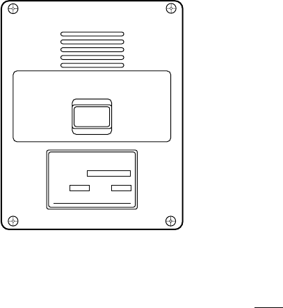
6-3
Transmitting a Distress Alert
1. Open cover on DISTRESS button.
2. Press the DISTRESS button 4 seconds on Distress Alert Unit IC-
302.
Note: Within 3 seconds, the distress alert will not be tramsmitted.
The lamp inside the button flashes quickly and an audible alarm
sounds intermittently. Four seconds later, the distress alert is trans-
mitted and light the lamp and an audible alarm sounds continu-
ously. When you receive acknowledgment of the distress alert
from an LES, the lamp flashes slowly and the audible alarm sounds
intermittently.
To silence the audible alarm, press [F10].
DISTRESS
TYPE IC-302
SEL NO.
COMPASS SAFE DISTANCE
STD M
FURUNO ELECTRIC CO., LTD
Figure 6-4 Distress Alert Unit IC-302
Do not press the button to silence an alarm for incoming distress
or urgent message. This will transmit a distress alert for own ship.

6-4
Testing Distress Button
The DISTRESS button on the IC-302 may be tested without trans-
mitting the distress signal as follows:
1. Press [F7] to display the Options menu.
2. Press [6] to display the Test menu.
1. PV Test
2. PV Test Result
3. Self Test
4. Distress Alarm Button Test
Test
Figure 6-5 Test Menu
3. Press [4].
4. Press [Enter]. The Distress Alert Button Test mode screen appears.
1. Login
2. Logout
3. Abort
4. Select NCS
5. Ocean Region
6. Test
Options
1. PV Test
2. PV Test Result
3. Self Test
4. Distress Alarm Button Test
Test
Distress alert button test mode.
Press any key to escape.
Distress Alert Button Test
Figure 6-6 Distress alert button mode screen
5. Open cover on DISTRESS button.
6. Press the DISTRESS button 4 seconds.
7. Confirm that the IC-302 sounds the audible alarm.
8. Close the cover on DISTRESS button.
9. Press any key to escape.

6-5
Distress Communications
The distress alert provides the minimum distress reporting require-
ments: own vessel’s ID, speed, course, L/L position and nature of
distress. After receiving the distress alert acknowledgment and you
are not pressed for time you may send detailed information as fol-
lows:
1. Press [F1] followed by [Enter] to display the editor screen.
2. Prepare distress communication message. Figure 6-7 shows a
sample distress message.
MAYDAY MAYDAY MAYDAY
THE NAME IS
I NEED HELP
Ship’s name
: Type of assistance required
Figure 6-7 Sample distress message
3. Press [F3].
4. Press [Enter]. The screen should look something like Figure 6-8.
The cursor is on the Priority line.
25 Char. [ Line 2/ 2 Col. 1 ]
<[1] UNTITLED1>
0001|t
----
*
---------
+
---------
+
---------
+
---------
+
---------
+
---------
+
---------
<
[Insert ]
Transmit
1. Transmit Message
2. Cancel
3. Request Delivery Status
Transmit Message
Priority
Message File
Station Name
Destination Type
Prefix Code
Country/Ocean Code
Station ID
Modem Type
Address
Subject
Attach File
LES ID
Option
[ TRANSMIT ]
Normal
Message now being edited Size 63
TELEX
Figure 6-8 Transmit message screen
5. Press [Enter] to open the selection window.
6. Press [
/
] to select “Distress”.
7. Press [Enter] to close the selection window.
8. Press [
/
] to go the LES ID line.
9. Press [Enter] to open the LES list.
10. Select the LES where the distress alert was transmitted.

6-6
11. Press [Enter] to close the LES list.
12. Press [
/
] to place the cursor on TRANSMIT.
13. Press [Enter]. The display should look similar to Figure 6-9.
25 Char. [ Line 2/ 2 Col. 1 ]
<[1] UNTITLED1>
0001|t
----
*
---------
+
---------
+
---------
+
---------
+
---------
+
---------
+
---------
<
[Insert ]
Transmit
1. Transmit Message
2. Cancel
3. Request Delivery Status
Transmit Message
Priority
Message File
Station Name
Destination Type
Prefix Code
Country/Ocean Code
Station ID
Modem Type
Address
Subject
Attach File
LES ID
Option
[ TRANSMIT ]
Distress
Message now being edited Size 63
TELEX
000
SEARCH AND RESCUE
303 (YAMAGUCHI) Start
NoYes
Figure 6-9 Transmit message screen with send start confirmation
prompt
14. Press [Enter] to transmit the distress message to the LES.
Note: Country/Ocean Code and Station ID are not required in a
distress message.

7-1
OTHER FUNCTIONS
This chapter describes how to abort operation, scan NCS and select
EGC and NCS channels.
Aborting an Operation
You can abort transmission, receiving or scanning during operation.
1. Press [F7] to display the Options menu.
1. Login
2. Logout
3. Abort
4. Select NCS
5. Ocean Region
6. Test
Options
Figure 7-1 Options menu
Note: If the FELCOM 12 is set to operate as an EGC-only re-
ceiver, the menu looks like this:
1. Login
2. Logout
3. Abort
4. Select EGC Ch.
5. Test
Options
Figure 7-2 Options menu, EGC-only receiver status
2. Press [3] to select Abort.
1. Login
2. Logout
3. Abort
4. Select NCS
5. Ocean Region
6. Test
Options
Abort
Start
NoYes
Figure 7-3 Abort screen
3. Press [Enter] to abort. (The message “Forced Clearing” replaces
either Sending, Receiving or Scanning at the bottom of the screen.)
Note: Aborting is possible in sending, receiving or scanning. If
attempted in other operating modes “Cannot abort cur-
rent process.” appears.
7-2
Scanning NCS
The communication unit automatically tunes itself to the NCS se-
lected on the System Setup menu. You can, however, tune to another
NCS which has a stronger signal. Scanning is possible only when the
communication unit is IDLE and FELCOM 12 is set to operate as an
Inmarsat-C transceiver.
If the communication unit is not idle, “Communication unit is not
Idle now. Cannot start scan.” appears. Press any key to escape then
wait until the unit is in the idle state.
1. Press [F7] to display the Options menu.
2. Press [5] to display the Ocean Region screen.
1. Login
2. Logout
3. Abort
4. Select NCS
5. Ocean Region
6. Test
Options
Ocean Region
Auto
West-Atlantic
East-Atlantic
Pacific
Indian
NCS you are currently tuned to appears in reverse indication.
Figure 7-4 Ocean region screen
3. The NCS you are currently tuned to appears in reverse indication.
If necessary, select another NCS.
4. Press [Enter].
If Auto is selected, FELCOM 12 scans all NCSs in turn. If a par-
ticular ocean region is selected, FELCOM 12 scans all channels
of that NCS. (NCSs will begin using multiple channels when the
third generation satellites come into use.)
1. Login
2. Logout
3. Abort
4. Select NCS
5. Ocean Region
6. Test
Options
Ocean Region
Auto
West-Atlantic
East-Atlantic
Pacific
Indian
Start
NoYes
Figure 7-5 NCS scan confirmation screen
5. Press [Enter] to start the scanning.
The message “Starting Scan Process. Press any key to escape.”
appears during the scanning.
7-3
Selecting EGC Receiving Channel
EGC channel can be selected when the DTE is set to operate as an
EGC-only receiver. This procedure is shown for reference; currently
there is only one EGC channel per NCS.
1. Press [F8] to display the Setup menu.
2. Press [9] to display the Configuration menu.
3. Press [3]. The EGC channel which the EGC receiver is currently
tuned to appears on the display in reverse indication.
File Edit Transmit EGC Reports logs Options Setup Position StopAlarm
Date
Time
Position
Waypoint
Course
Speed
Current NCS
Current Channel
Current TDM
MES Status
GPS Status
DCE Memory
97-08-21
06:12 (UTC)
LAT
LON
LAT
LON
DEG
KTS
344 (IOR) LOGIN
NCS CC
NCS CC
Idle
****
32818 Bytes free
BBER
C/N
Send Level
RxIF AGC Level
REF Offset Freq
Synthe 1st -1 Local
1st -2 Local
RX2nd Local
Antenna Power Supply
Water Temperature
Water Current
Direction
Speed
Depth
004
OK ( 39dB)
OK ( 0)
OK (134)
OK ( 0Hz)
OK
OK
OK
OK
DEG
DEG
KTS
SYNC ( NCS )
NCS: IOR LOGOUT
97-08-21 02:00 (UTC)
LAT: 00:00.00N
LON: 000:00.00E
35:00.00N
135:00.00E
Setup
EGC Channel List
11080* 12580* 10840* 11088*
ENT: set ESC: quit
Current State: EGC RECEIVER
DCE Ver **
Configration
Figure 7-6 EGC channel list screen
4. Select desired channel.
5. Press [Enter] to start the tuning.
6. Press [Esc] to close the Update screen.
7. Press [Enter] to select “Yes”.

7-4
Selecting NCS Channel
NCS channel can be selected as shown in the procedure below. Cur-
rently, each satellite transmits one global beam. In the future, the sat-
ellites will transmit multiple spot beams, namely, the NCS will have
multiple channels.
1. Press [F7] to display the Options menu.
2. Press [4] to display the Select NCS menu. The NCS Channel
List appears.
NCS channels programmed at page 2-16 appear on the list.
1. Login
2. Logout
3. Abort
4. Select NCS
5. Ocean Region
6. Test
O
p
ti
ons
NCS Channel List
No AOR (WEST)
FREQ
11080*
ID
044
0
0
0
0
0
0
0
1
2
3
4
5
6
7
8
ENT: set ESC: quit
AOR (EAST)
FREQ
12580*
ID
144
1
1
1
1
1
1
1
POR
FREQ
12580*
ID
244
2
2
2
2
2
2
2
IOR
FREQ
10840*
ID
344
3
3
3
3
3
3
3
Figure 7-7 NCS channel list
3. Select NCS channel.
4. Press [Enter].
5. Press [Esc] to close the Update screen.
6. Press [Enter] to select “Yes”.
The unit tunes to the channel selected.
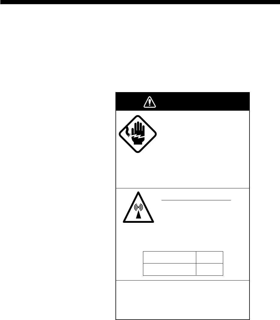
8-1
MAINTENANCE
This chapter provides the information necessary for the maintenance
and checking of the FELCOM 12.
Safety Information
WARNING
WARNING
Do not open the cover of
the equipment.
This equipment uses high
voltage electricity which can
shock, burn, or cause
serious injury. Only qualified
personnel should work inside
the equipment.
Hazardous microwave
Do not approach within 60
cm of the antenna radome
when it is transmitting.
Microwave radiation can be harmful to the
human body, particularly the eyes.
Do not disassemble the equipment.
Fire, electrical shock or serious injury may
result.
Radiation Level
10W/m2
At
60 cm
8-2
General Checking and Maintenance
Turn off the power before conducting any maintenance procedures
other than the cleaning of the terminal unit and communication unit.
Cleaning the terminal unit and communication
unit
These units can be cleaned with a soft, dry cloth. DO NOT use chemi-
cal cleaners. They may remove paint and markings.
Checking connectors and earth terminal
The connectors and earth terminal on the rear panel of the communi-
cation unit and on the bottom panel of the terminal unit should be
checked periodically for tightness. If the earth terminal has rusted,
clean it.
Floppy disk drive head
The floppy disk is coated with a magnetic material which stores in-
formation entered into the disk. If this material is damaged by for-
eign material adhering to the disk drive head it may not be possible to
read from or write to the disk. Clean the head regularly with a clean-
ing floppy disk to prevent loss of data.
When the power can’t be turned on (power lamp
does not light)
3) and 4) are for service technicians.
1) Check the power cable connector on both the rear panel of the
terminal unit and communication unit for tightness. Check if the
ship’s mains switchboard is turned on.
2) On the terminal unit, check the breaker on the rear panel. If it has
tripped it will be protruding several millimeters. Reset it if neces-
sary.
3) On the rear panel of the terminal unit, disconnect the power cable.
Connect a multimeter to the power cable connector and confirm
21.6 and 31.2 V. (pin #1: positive, pin #2: negative)
4) On the rear panel of the communication unit, disconnect the power
cable. Connect a multimeter to the power cable connector and
confirm 21.6 and 31.2 V. (pin #1 and #2: positive, pin #3 and #4:
negative)

8-3
Self Tests
The communication unit and the terminal unit are equipped with self
tests which check them for proper operation.
Self test at power application (communication
unit)
The communication unit performs the following tests when it is turned
on:
a) ROM sum test
b) RAM read and write test
c) DP RAM read and write test
d) EEPROM sum test
e) VITERBI decoder test
If the unit finds no fault it goes into normal operation.
Testing the communication unit through the
keyboard
This test can only be initiated from the main DTE. The communica-
tion unit must be idle.
1. Press [F7] to display the Options menu.
2. Press [6] to display the Test menu.
3. Press [3]. The Communication Unit (self test) screen appears.
1. Login
2. Logout
3. Abort
4. Select NCS
5. Ocean Region
6. Test
Options
1. PV Test
2. PV Test Result
3. Self Test
4. Distress Alarm Button Test
Test
Communication Unit
Start
No
Yes
Yes
Figure 8-1 Communication unit screen
4. Press [Enter] to start the test.
The message “Now Communication Unit-testing” appears in
blinking reverse video during testing.

8-4
5. When the test is completed the screen shows the results of the
test.
1. Login
2. Logout
3. Abort
4. Select NCS
5. Ocean Region
6. Test
Options
1. PV Test
2. PV Test Result
3. Self Test
4. Distress Alarm Button Test
Test
CPU1
ROM
RAM
DP-RAM
Viterbi
Press any key to escape.
165-0086-100
OK
OK
OK
OK
CPU2
ROM
RAM1
RAM2
EEPROM
GPS
DP-RAM
165-0087-103
OK
OK
OK
OK
OK
OK
Communication Unit
Figure 8-2 Sample communication unit self test results
Either “OK” or “NG” (No Good) appears next to each ROM and
RAM tested. NG display releases the audible alarm. For defec-
tive ROM, RAM, DP-RAM, EEPROM or VITERBI replace the
CPU Board. For GPS, NG appears when there is no GPS board or
it is faulty.
6. Press any key to finish the communication unit test.
Performance Verification (PV) Test
After the FELCOM 12 is installed, the installing technician usually
confirms that the unit is functioning properly and is logged in with
the Inamarsat C system by conducting the PV test.
The PV test consists of the message reception test, message transmis-
sion test and distress alert test.
The results of the test appear on the PV test result display.
Note that the test cannot be conducted from a 2nd DTE. Note also
that the test can be initiated by a LES.
PV test sequence
1. Select PV Test on the Test menu.
2. The NCS acknowledges request for testing.
3. The MES, upon receiving acknowledgment from NCS, goes into
pending state.
4. NCS will select a (not busy) LES to perform the test.
5. The LES transmits a test message to the MES.
6. MES transmits a test message to the designated LES.
7. LES receives test message.

8-5
8. The MES automatically transmits the distress alert test within two
minutes after completion of step 8.
9. When the distress alert test is finished the results of the test are
sent to MES.
The entire PV test can be conducted automatically (taking about
15 minutes in total).
PV test procedure
1. Confirm that the communication unit is in idle condition and
logged in.
2. Press [F7] to display the Options menu.
3. Press [6] to display the Test menu.
4. Press [1] to select PV Test.
1. Login
2. Logout
3. Abort
4. Select NCS
5. Ocean Region
6. Test
Options
1. PV Test
2. PV Test Result
3. Self Test
4. Distress Alarm Button Test
Test
PV Test
Start
No
Yes
Yes
Figure 8-3 PV test screen
Note: If the communication unit is not idle when the test is initi-
ated the screen displays “MES is not idle now. Cannot start
PV Test.” And if not logged in, “Cannot start PV Test. (not
Logged-in)” appears.
5. Press [Enter] to transmit the PV test request to NCS.
1. Login
2. Logout
3. Abort
4. Select NCS
5. Ocean Region
6. Test
Options
1. PV Test
2. PV Test Result
3. Self Test
4. Distress Alarm Button Test
Test
Starting PV Test Process.
Automatic test mode: Normal communication disabled.
Do not press any distress button unless you are in distress.
PV Test
Figure 8-4 PV test screen
6. Press [Esc] to return to the standby display.
7. The screen displays “Current State: Idle (pending!)” when the
acknowledge signal is received from the NCS.
8. When testing begins the screen displays “Current State: TEST-
ING”.
9. Transmit a message to the LES. The LES, after acknowledging
receipt of your message, transmits a message to you.

8-6
10. Though a prompt asks you to test distress alert, do not press any
key. The alert test is automatically conducted two minutes later.
11. When testing is completed the indication TESTING is replaced
by IDLE.
12. The test results appear on the PV Test Result screen. (The next
section shows how to interpret the results.)
Results of PV test
1. At the standby display, press [F7] to display the Options menu.
2. Press [6] to display the Test menu.
1. Login
2. Logout
3. Abort
4. Select NCS
5. Ocean Region
6. Test
Options
1. PV Test
2. PV Test Result
3. Self Test
4. Distress Alarm Button Test
Test
Figure 8-5 Test menu
3. Press [2] to display the results of the PV test.
1. Login
2. Logout
3. Abort
4. Select NCS
5. Ocean Region
6. Test
Options
1. PV Test
2. PV Test Result
3. Self Test
4. Distress Alarm Button Test
Test
Test Date & Time
Attempts
BBER
Shore-to-Ship Attempts
Ship-to Shore Attempts
Distress Alert
Signal strength
Overall Result
97-08-26 01:58 (UTC)
First attempt
Pass
First attempt
First attempt
Pass (Test OK)
Pass (Greater than Std level + 6dB)
Pass (Applicable tests pass)
Ctrl+P: print ESC: quit
PV Test Result
Figure 8-6 Sample PV test results
Note: If the communication unit is off or malfunctioning, “DCE
error: No response from DCE!!” appears. Check the con-
nection between the communication unit and the terminal
unit.
4. To escape, press any key. The standby display appears.
Interpreting the PV tests results display
Test Date & Time: Date and time of test
Attempts: Number of times the PV test was con-
ducted.

8-7
BBER: Bulletin Board Error Rate (%). Pass ap-
pears for no error.
Shore-to-Ship Attempts: Number of tests initiated by LES.
Ship-to-Shore Attempts: Number of tests initiated by MES.
Distress Alert: “Pass (Test OK)” appears for successful
testing.
Signal Strength: “Pass” appears if signal strength is greater
than standard level.
Overall Result: “Pass” appears for satisfactory comple-
tion of test.
System Status Monitor
The system status monitor, which is always displayed, provides date,
time, equipment status and navigation data on one screen.
File Edit Transmit EGC Reports logs Options Setup Position StopAlarm
Date
Time
Position
Waypoint
Course
Speed
Current NCS
Current Channel
Current TDM
MES Status
GPS Status
DCE Memory
97-08-21
06:12 (UTC)
LAT
LON
LAT
LON
DEG
KTS
344 (IOR) LOGIN
LES TDM
LES TDM
Busy
****
32818 Bytes free
BBER
C/N
Send Level
RxIF AGC Level
REF Offset Freq
Synthe 1st-1 Local
1st-2 Local
RX2nd Local
Antenna Power Supply
Water Temperature
Water Current
Direction
Speed
Depth
004
OK ( 38dB)
OK ( 0)
OK (133)
OK ( 0Hz)
OK
OK
OK
OK
DEG
DEG
KTS
Current State: TESTING
TEST--RECEIVING MESSAGE
DCE Ver 03 Oct-1996
SYNC ( LES )
NCS: IOR LOGIN
97-08-21 06:12 (UTC)
LAT: 35:00.00N
LON: 135:00.00E
35:00.00N
135:00.00E
Figure 8-7 System status monitor display
8-8
Interpreting the system status monitor
Date: Current date
Time: Current time
Position: Vessel’s position (either manual entry or au-
tomatic input by navigation aid)
Waypoint: Destination
Course: Heading
Speed: Ship’s speed
Current NCS: NCS your vessel is logged in with
Current Channel: Channel in use
Current TDM: Channel TDM
MES Status: Operational status of MES
GPS Status: Receiving signal status from GPS receiver.
CST: Cold Start
ACK: Acquired; Almanac data acquired
IMP: Impossible; cannot receive GPS signal
INT: Interrupted; object interfering reception
of GPS signal
ALM: Receiving the almanac
2D, 3D: Position-fixing method by 2 or 3 di-
mension
Note: The above status indication depends on the GPS
receiver connected.
DCE memory: Memory remaining in communication unit
BBER: Bulletin Board Error Rate (%)
C/N: Check of circuit status with LES, receiving
circuit in antenna unit, RF CON Board and
CPU Board (DEMOD section). OK appears
for figure greater than 31.
Send Level: TX level check. At transmission, OK appear
for more than 123. At reception OK appears
for figure less than 32.
RX IF AGC Level: Check the receiving circuit of the antenna unit
and the RF CON Board in the communica-
tion unit. OK appears for figure greater than
80.
8-9
REF Offset Freq: Operating normally. If it does not light check
RX Synthesizer or REF OSC in the RF CON
Board. OK appears for figure less than 150.
Synthe 1st Local: Check of RF CON Board.
RX 2nd Local: Check of RF CON Board 2nd local oscilla-
tor.
Antenna Power Supply:
NG appears for discontinuity or short in cable.
Temperature*: Water temperature
Water Current*
Direction: Tidal current direction
Speed: Tidal current speed
Depth*: Depth of water
Note: * requires data from the navigation device.
Replacing Internal Battery
A lithium battery in the communication unit is used to backup system
settings. The life of this battery is about five years, however actual
life depends on usage when the battery is dead the communication
unit automatically reverts to default system settings. Contact you
dealer to request replacement of the battery.
Name: BTT(L1)
Code No.: 000-103-769
Type: CR1/2 8.L-F

8-10
Error Messages
This section shows the error messages which may appear on the screen
and the means to remedy the associated problem. If normal operation
cannot be restored, contact your dearer to request repair.
egassemrorrEgninaeMnoitcA
gnillangiS lennahC .noitsegnoc
lennahc(tekcaPgnillangiS ,tseuqertnemngissa ,gnitroperatad,llacssertsid ,dettimsnartsi).cte gnillangisSESrevewoh ysubsilennahc
gnitacinummocyrT retalataniaga .emit
.MDTtsoLnoisiviDemiT(MDT tonsilennahc)xelpitluM wodahsybdezinorhcnys .rotces
lliwegassemrorrE retfaraeppasid tsapgnissap .rotceswodahs
ynamooT .seirter tinunoitacinummoC dnammocemasstaeper
.deliafnigoL.nigoltondluoCgnitacinummocyrT retalataniaga tcepsuS.emit elbuorttnempiuqe sliafnigolfi yltneuqerf
nigoL!tuoemiT -megdelwonkcA tontne .deviecer
sitnemegdelwonkcAnigoL .emitnodeviecerton gnitacinummocyrT retalataniaga tcepsuS.emit elbuorttnempiuqe sliafnigolfi yltneuqerf
decroF .deliafgniraelC deliafraelcdecroF
gnidneS .deliafegassem .tnesebtondluocegasseMgnitacinummocyrT retalataniaga emit
gnidneS egassem .detroba
sawegassemgnidneS .detroba gnitacinummocyrT retalataniaga emit
gnidneS egassem SELybdetroba ...foesuaceb
sawegassemgnidneS dnaL(SELybdetroba .)noitatShtraE
gnitacinummocyrT retalataniaga emit
SELdetceleS nitsixeton .noigertnerruc
ottimsnarttonnacuoY .aeratnerrucniSEL tnereffidtceleS SEL
gnillangiSSEM gnirud,eruliaF gnidnes .egassem
lennahcgnillangisSES gnidnesgniruddeliaf .egassem
niagatimsnarteR emitretalata
egasseM ,eruliafgnidnes dezirohtuanu DI_SELDIND .erap
.egassemdnestondluoC DINDtpeccatondluocSEL krowteNgnitroperataD( .)DI
hcihwSELtceleS .DINDseldnah

8-11
egassemrorrEgninaeMnoitcA
sutatSyrevileD sitseuqeR .deliaf
ebtondluocsutatsyrevileD demrifnoc tseuqer-eR .sutatsyreviled
sutatSyrevileD sitseuqeR .detroba
sawtseuqersutatsyrevileD .detroba
gnivieceR .deliafegassem ebtondluocegasseM .deviecer -ersiegasseM deviecer .yllacitamotua
gnivieceR egassem .detroba
elihwdetrobaegasseM .deviecergnieb -ersiegasseM deviecer .yllacitamotua
gnillangiSSEM gnirud,eruliaF gniviecer .egassem
lennahcgnillangisSES sawegassemelihwdeliaf .deviecergnieb
-ersiegasseM deviecer .yllacitamotua
gnivieceR egassem SELybdetroba ...foesuaceb
-ersiegasseM deviecer .yllacitamotua
trelAssertsiD .detrobatseT sawtsettrelassertsiD tsetVPgniruddetroba noitacifireVecnamrofreP( .)tset
trelAssertsiD .deliaftseT deliaftsettrelassertsiD tsetVPgnirud noitacifireVecnamrofreP( .)tset
tatsetVPtcudnoC .emitretala
siTSETVP .deliaf tatsetVPtcudnoC .emitretala
siTSETVP .detroba tatsetVPtcudnoC .emitretala
gnillangiSSEM gnirud,eruliaF .TSETVP
tsollennahcgnillangisSES .tsetVPgnirud tatsetVPtcudnoC .emitretala
tseTgnivieceR ,eruliaF elihwtuoemiT SCNnognitiaw .CC
krowteN(CCSCN noitatsnoitanidrooc gniviecer)lennahcnommoc .deliaftset
tatsetVPtcudnoC .emitretala
tseTgnidneS ooT,eruliaF .seirterynam
tatsetVPtcudnoC .emitretala
siTSETVP SELybdetroba ...foesuaceb
tatsetVPtcudnoC .emitretala
siTSETVP SELybgnidnep ...foesuaceb
-ersitsetVP detrats .yllacitamotua
siTSETVP SELybdetcejer ...foesuaceb
tatsetVPtcudnoC .emitretala

8-12
egassemrorrEgninaeMnoitcA
tropeRataD ,deliaf dezirohtuanu .DIND
gnitroperataD(DIND .teston)DIkrowteN gnivahSELtceleS .DIND
:GNINRAW revoREBB gninnacS.%08 tratsSCN .yllaunam
draoBnitelluB(REBB .%08dedeecxeetar)rorrE SCNtceleS royllaunam .yllacitamotua
:GNINRAW dniftonnaC niCCSCN derreferp .noiger llagninnacS sinoiger .detrats
ebtondluocfI ,CCSCNdnuof ruoytcatnoc tseuqerotreraed .riaper
:ELBUORT rewopreirraC .level
ta,tondluoctnerrucxT detcetedeb,noissimsnart .GERWSyb
metsyskcehC rofrotinomsutats .dnes
:ELBUORT rezisehtnyS .KCOLNU
.eruliaftiucricrezisehtnyS.riapertseuqeR
:GNINRAW roflluFyromeM eviecer .egassem
xRevastondluoC .egassem ehtnonruT fotinUlanimreT .1ETDgnitcennoc
:GNINRAW egasseM rofdeviecer .TROP1ETD nonrutesaelP trop1ETD .tnempiuqe
neewtebnoitacinummoC dna)tinUlanimreT(1ETD .deliaftinUnoitacinummoC
ehtkcehC gnitcennoc 1ETDneewteb dna noitacinummoC nonrutrotinU .tinUlanimreT
:GNINRAW VANlanretxE tnempiuqe .eruliaf
tupniatadnoitagivanoN .ecivednoitagivanmorf noitagivankcehC .ecived
esaelP:FNI tnerrucetadpu .noitisoppihs
tonsinoitisoppihstnerruC .detadpu tnerrucetadpU .noitisoppihs
:GNINRAW SPGlanretnI .eruliafTINU
ebtondluoclangisSPG .detceted tinuSPGlanretnI degamadebthgim siegassemsihtfi deyalpsid tcatnoC.yltneuqerf otrelaedruoy .riapertseuqer
VP:derongI neebsahTSET ,detratsydaerla wondna .gnidnep
tcudnocotdetpmettauoY sitsetVPnehwtsetVP .gnidnepydaerla
erawdrahSEL .detcetedrorre eviecertonnacSEL sawegassemroegassem .semitevifdetpeccaton
simetsysxT roelbatsnu .elbuorttnempiuqe

8-13
egassemrorrEgninaeMnoitcA
locotorpSEL .detcetedrorre fielbuorttcepsuS sihtnehw siegassem deyalpsid .yltneuqerf
.ecivresdilavnitcerroctupnI .edocecivres
.sserddadilavnitcerroctupnI .sserdda
This page is intentionally left blank.

SP-1
SPECIFICATIONS
Transmitting Frequency 1626.5 to 1646.5 MHz
Receiving Frequency 1530.0 to 1545.0 MHz
Antenna Omnidirectional
G/T Better than -23 dB/K (elevation angle 5˚)
EIRP 12 to 16 dBW (elevation angle 5˚)
Modulation BPSK
Modulation Rate 1200 sps
Coding Convolutional coding with coding rate
1/2 and constraint length 7
Decoding Viterbi decoder
Transmission Speed 600 bps
External Equipment Interface Input: GGA, GLL, RMA, RMC, ZDA, VTG, RMB,
WPL, MTW, DBT, VDR, BWC, BWR
Output: GGA, ZDA, GLL, VTG, RMC, GSV
Internal GPS Receiver (option) Eight discrete channels, all-in-view
Approx. 50 m, 95% of the time, Horizontal dilution of
position (HDOP)<4
All GPS receivers are subject to degradation of position
and velocity accuracies under the U.S. Department of
Defense.
Navigation Equipment Interface Internal GPS Board (option): NMEA0183
Operating Environment Above deck equipment
Temperature: -35˚C to +55˚C
Relative humidity: 95% (at 40˚C)
Below deck equipment
Temperature: -20˚C to +55˚C
Relative humidity: 95% (at 40˚C)
Ship’s Mains Communication unit, Terminal unit and Printer: 24VDC
100/110/120/200/220/240 VAC by optional AC-DC
Power Supply Unit PR-300]
SP-2
Power Consumption IC-112 & IC-212: Receiving 25W, Transmitting 120W
IB-581: 18W
PP-510: 36 W MAX
Color Antenna unit: N9.5
Antenna unit base: 2.5PB3.5/10
Communication unit: N3.0
Terminal unit: Cover: 2.5GY5/1.5
Panel: N3.0
Distress alert unit: 2.5GY5/1.5
Received call unit: 2.5GY5/1.5
Waterproofing: Antenna unit: IEC529 IPX6
Communication unit: IEC529 IPX2
Terminal unit: IEC529 IPX0

AP-1
APPENDIX
International Telex/Telephone Country Code List
Area and Country Remarks for Telex Code
Telephone
Country Code Telex Country
Code
Afghanistan
Alaska
Albania
Algeria
American Samoa
American Virgin Is.
Andorra
Angola
Anguilla
Antigua & Barbuda
Argentina
Armenia
Aruba
Ascension
Australia
Australian External
Territories
Austria
Azerbaijani
Azores Is.
Bahamas
Bahrain
Bangladesh
Barbados
Belarus
Belgium
Belize
Benin
Bermuda
Bhutan
Bolivia (Rep. of)
Bolivia (ENTAL)
Bosnia-Hercegovina
Botswana
Brazil
British Virgin Is.
Brunei Darussalam
Bulgaria
Burkina Faso
Burundi
Telex calls to former WUI subscribers, insert the figure
“9” after the destination code “208”.
Disregard the figure “0” at head of subscriber number.
Subscriber numbers are 2XXX or 5XXX
Manual calls 3XXX
Destination code is the same as for Portugal.
Disregard the figure “0” at head of subscriber number.
93
1
355
21
684
1
33
244
1
2
54
7
297
247
61
672
43
994
351
1
973
880
1
7
32
501
229
1
975
591
387
267
55
1
673
359
226
257
79
200
604
408
770
208
590
991
391
393
33
684
303
939
71
766
47
784
404
297
490
780
392
681
46
371
972
290
890
371
309
600
962
38
292
809
67
978
903

AP-2
Area and Country Remarks for Telex Code
Telephone
Country Code Telex Country
Code
Cambodia
Cameroon
Canada
Canary Is.
Cape Verde
Cayman Is.
Central Africa Rep.
Chad
Chile
China
Christmas Is. (Aus)
CIS (formerly USSR)
Cocos-Keeling Is.
Colombia
Comoros
Congo
Cook Is.
Costa Rica
Cote d’ lvoire
Croatia
Cuba
Cyprus
Czechoslovakia
Denmark
Diego Garcia
Djibouti
Dominica
Dominican Rep.
Ecuador
Egypt
El Salvador
Estonia
(formerly USSR)
Ethiopia
Kampuchea Rep.
Disregard the figure “0” at head of subscriber number.
Destination code is the same as for Spain.
TCH subscribers 2XXXXX
ENTEL subscribers 5XXXXX
TRA subscribers 3XXXXX
TECOM subscribers 6XXXXX
VTR CM subscribers 4XXXXX
Disregard the figure “0” at head of subscriber number.
Manual calls
Ivory Coast
RCA subscribers 4XXXXX
For subscriber number beginning with 346, disregard
“346” at head of subscriber number.
AGEM IR subscribers 61XX
855
237
1
34
238
1
236
235
56
86
672
7
672
57
269
242
682
506
225
385
53
357
42
45
246
253
1
1
593
20
503
372
251
807
970
21
26
52
993
293
971
976
34
85
766
64
766
35
994
981
772
376
983
599
28
605
66
55
938
979
394
201
202
241
308
91
373
537
980

AP-3
Area and Country Remarks for Telex Code
Telephone
Country Code Telex Country
Code
Falkland Is. (Malvinas)
Faroe Is.
Fiji
Finland
France
French Guiana
French Polynesia
Gabon
Gambia
Georgia
Germany (Fed, Rep. of)
Ghana
Gibraltar
Greece
Greenland
Grenada
Guadeloupe
Guam (RCA)
Guatemala
Guiana
Guinea Conakry
Guinea Bissau
Guyana
Haiti
Hawaii
Honduras
Hong Kong
Hungary
Iceland
India
Indonesia
Iran
Iraq
Ireland
Israel
Italy
formerly East Germany
formerly West Germany
Manual calls
RCA subscribers 9XXX
RCA subscribers 8XXX or 2968XX
ITT subscribers 743XXX
WUI subscribers 63XXX or 63XXXX
WUH subscribers 39XXXX
Telex calls to HTC subscribers can be made using
Semi-automatic calls.
Disregard the figure “0” at head of subscriber number.
Disregard the figure “0” at head of subscriber number.
500
298
679
358
33
594
689
241
220
7
49
49
233
350
30
299
1
590
671
502
594
224
245
592
509
1
504
852
36
354
91
62
98
964
353
972
39
306
502
701
57
42
300
702
973
996
683
69
41
94
405
601
503
395
299
700
372
300
995
969
295
203
704
705
708
709
(773)
374
802
61
501
81
73
88
491
500
606
43

AP-4
Area and Country Remarks for Telex Code
Telephone
Country Code Telex Country
Code
Jamaica
Japan
Jordan
Kazakhstan
Kenya
Kiribati
Korea (Demo, People’s
Rep. of)
Korea (Rep. of)
Kuwait
Kyrgyzstan
Lao
Latvia (formerly USSR)
Lebanon
Lesotho
Liberia
Libya
Liechtenstein
Lithunia
(formerly USSR)
Luxembourg
Macao
Macedonia
Madagascar
Madeira Is.
Malawi
Malaysia
Maldives Is.
Mali
Malta
Mariana Is.
Marshall Is.
Maritinique
Mauritania
Mauritius
Mexico
Micronesia
Moldova
Monaco
Mongolia
KDD (for 5 digits)
NTT
Subscriber numbers are 770XX
Subscriber number beginning with 4, 5, 7, 8 and 9 can
be reached by Manual Calls.
Destination code is the same as for Portugal.
Subscriber number beginning with 11XX can be
reached by Semi-automatic calls.
Disregard the figure “0” at head of subscriber number.
Destination code is the same as for France.
1
81
962
7
254
686
850
82
965
7
856
371
961
266
231
21
41
370
352
853
389
261
351
265
60
960
223
356
671
692
596
222
230
52
691
373
33
976
291
72
720
493
785
987
761
(899)
801
496
788
804
538
494
963
997
901
45
539
402
808
597
986
404
904
84
896
985
406
403
760
765
298
974
966
22
764
682
42
800

AP-5
Area and Country Remarks for Telex Code
Telephone
Country Code Telex Country
Code
Montserrat
Morocco
Mozambique
Myanmar
(formerly Burma)
Namibia
Nauru
Nepal
Netherlands
Netherlands Antilles
New Caledonia
New Zealand
Nicaragua
Niger
Nigeria
Niue Is.
Northern Mariana Is.
Norfolk Is.
Norway
Oman
Pakistan
Palau
Panama
Papua New Guinea
Paraguay
Peru
Philippines
Poland
Portugal
Puerto Rico
Qatar
2XXXX other numbers are for Semi-automatic calls.
TRT subscribers
AACR subscribers
INTEL subscribers
PHILCOM subscribers 2XXXX
RCPI subscribers 7XXXX
GMCR subscribers 4XXXX
ETPI subscribers 6XXXX
CAPWIRE subscribers 1XXXX
For PTT subscribers, insert the figure “8” after the
destination code “75”.
Disregard the figure “0” at head of subscriber number.
RCA subscribers 2XXX
ITT subscribers 345XXX
C&W, WUI subscribers
ACPR (PRCA) subscribers
1
21
258
95
264
674
977
31
599
687
64
505
227
234
683
670
672
47
968
92
680
507
675
595
51
63
48
351
1
974
396
407
992
83
908
775
891
44
390
706
74
375
975
905
776
766
56
498
82
763
377
378
379
703
305
36
75
63
404
205
206
207
209
497

AP-6
Area and Country Remarks for Telex Code
Telephone
Country Code Telex Country
Code
Reunion
Romania
Russian Federation
Rwanda
Saipan
San Marino
Sao Tome & Principe
Saudi Arabia
Senegal
Seychelles
Sierra Leone
Singapore
Slovak
Slovenia
Solomon Is.
Somalia
South Africa
Spain
Spanish North Africa
Sri Lanka
St. Helena
St. Kitts & Nevis
St. Lucia
St. Pierre & Miquelon
St. Vincent &
the Grenadines
Sudan
Suriname
Swaziland
Sweden
Switzerland
Syria
Tajikistan
Taiwan
Tanzania
Thailand
Togo
Tokelau
Tonga
Trinidad & Tobago
Tunisia
Turkey
Turkmenistan
Subscriber numbers are 916XXX
Disregard the figure “0” at head of subscriber number.
Manual calls
Cape Town subscribers XXXXXX
Bophuthatswana subscribers 08XXXX
Transkei subscribers 09XXX
Manual calls 4XXX
262
40
7
250
670
378
239
966
221
248
232
65
42
386
677
252
27
34
34
94
290
1
1
508
1
249
597
268
46
41
963
7
886
255
66
228
690
676
296
21
90
7
961
65
64
909
760
505
967
495
906
965
998
87
66
598
778
900
95
52
52
803
(960)
397
398
204
399
984
304
964
54
45
492
787
769
989
86
977
762
777
294
409
607
789

AP-7
Area and Country Remarks for Telex Code
Telephone
Country Code Telex Country
Code
Turks & Caicos Is.
Tuvalu
U. A. E.
Abu Dhabi
Ajman
Dubai
Fujairah
Ras Al Khaimah
Sharjah
Umm Al Qaiwain
Uganda
Ukraine
United Kingdom
United Arab Emirates
Upper Volta
Uruguay
Uzbekistan
U. S. A.
U. S. A. (Mainland)
U. S. S. R. (Former)
Vanuatu
Vatican
Venezuela
Viet Nam
Wallis & Futuna Is.
Western Samoa
Yemen (Rep. of)
Yugoslavia (Former)
2XXXX, 3XXXX, 5XXXX
695XX
4XXXX
8XXXX
9XXXX
68XXX
697XX
Same as “Burkina Faso”.
CCI subscribers 7XXXXXX
ITT subscribers 4XXXXX, 4XXXXXX, 4XXXXXXXXX
RCA subscribers 2XXXXX
WUI subscribers 6XXXX, 6XXXXX, 6XXXXXX
TRT subscribers 1XXXXX, 1XXXXXXXXX
FTCC subscribers 8XXXX, 8XXXXX
GRPHNET subscribers 36XXXXX, 37XXXXX
For WUT subscribers, insert the figure “0” after the
destination code “23”.
Telex calls to TWX subscribers whose numbers do not
contain “0” as the third figure of the 10 figure code can
be made as Semi-automatic calls.
Russian Federation
Subscriber number beginning with 561XXX can be
made using manual calls
Formerly Yemen (P. D. Rep. of)
Formerly Yemen (Arab Rep.)
1
688
971
256
7
44
971
226
598
7
1
7
678
379
58
84
681
685
969
967
296
774
893
988
680
51
893
978
32
786
23
23
25
640
771
504
31
805
707
779
806
895

AP-8
Area and Country Remarks for Telex Code
Telephone
Country Code Telex Country
Code
Ocean Area Remarks
Telephone
Ocean Region
Access Code
Telex Ocean
Region Access
Zaire
Zambia
Zanzibar
Zimbabwe
Telex calls to places other than Kinshasa Subscriber
beginning with 2XXXX can be made as Semi-automatic
calls.
243
260
259
263
982
902
990
907
AOR-W
AOR-E
POR
IOR
Atlantic Ocean-W
Atlantic Ocean-E
Pacific Ocean
Indian Ocean
874
871
872
873
584
581
582
583

AP-9
International Telex Abbreviations
Abbreviation Meaning
ADV Advise
ACK Acknowledge
AGN Again
BI (GS) Good bye
BK I cut off.
CFN Confirm
COL Collation
CRV How do you receive?
DER Out of order
DWN Down
EEE Error
FM From
GA Go ahead.
MNS Minutes
MOM Wait (Waiting)
MUTI Mutilated
NA Correspondence to this subscriber is not admitted.
NC No circuits
NCH Snbscriber’s number has been changed.
NP The called party is not or no longer is a subscriber.
NR Indicate your call number.
OCC Subscriber is engaged.
OK Agreed.
P (or 0) Stop your transmission.
PLS (PSE) Please
PPR Paper
P (RCD) Received
RAP I will call you again.
RD Reed
RE Referring to
RPT Repeat
SRY Sorry
SVP Please
TAX What is the charge?
TEST MSG Please send a test message?
THRU You are in communication with telex position
TKS (TNX) Thanks
TLX Telex

AP-10
Glossary of Acronyms
Acronym Meaning
AOR-E Atlantic Ocean Region-East
AOR-W Atlantic Ocean Region-West
BB Bulletin Board
BBER Bulletin Board Error Rate
BPSK Binary Phase Shift Keying
BS Back Space
C/N0 Carrier to Noise Power Spectral Density
CNID Close Network ID
CPU Central Processing Unit
CSDN Circuit Switched Data Network
DCE Data Circuit Terminating Equipment
DP-RAM Dual-Port Random Access Memory
DTE Data Terminal Equipment
EGC Enhanced Group Call
EIRP Equivalent Isotopically Radiated Power
FD Floppy Disk
GPS Global Positioning System
G/T Gain to Noise Temperature Ratio
HPA High Power Amplifier
IA5 International Alphabet No.5
ID Identity
IMO International Maritime Organization
INMARSAT International Mobile Satellite Organization
IOR Indian Ocean Region
ISDN Integrated Services Digital Network
ITA2 No.2 International Telegraphy Alphabet
ITU International Telecommunications Union
LES Land Earth Station
LNA Low Noise Amplifier
MES Mobile Earth Station
MSI Maritime Safety Information
NAVAREA Navigational Area
NAVTEX MF Navigational Broadcast Service
NCS Network Coordination Station
NMEA National Maritime Electronics Association
OCC Operation Control Center
PEP Packet Error Probability
POR Pacific Ocean Region
PSDN Packet Switched Data Network
PSTN Public Switched Telephone Network
PVT Performance Verification Test
RAM Random Access Memory
RCC Rescue Coordination Center
ROM Read Only Memory
SCC Satellite Control Center
SFU Store and Forward Unit
SOLAS Safety of Life at Sea
TDM Time Division Multiplex
TDMA Time Division Multiple Access
UTC Coordinated Universal Time
WMO World Meteorological Organization

AP-11
International Telegraphy Alphabet
No.
1
2
3
4
5
6
7
8
9
10
11
12
13
14
15
16
FIGURES
?
:
3
8
BELL
(
)
.
,
9
0
LETTERS
A
B
C
D
E
F
G
H
I
J
K
L
M
N
O
P
No.
17
18
19
20
21
22
23
24
25
26
27
28
29
30
31
32
FIGURES
1
4
’
5
7
=
2
/
6
+
LETTERS
Q
R
S
T
U
V
W
X
Y
Z
CARRIAGE RETURN
LINE FEED
LETTERS
FIGURES
SPACE
BLANK
AP-12
Error Messages and Alerts
A file by that name already exists on FD.
This message appears when you attempt
to copy a file from the internal memory to
a floppy disk and a file by that name al-
ready exists on the disk.
Cannot use this LES. Please check network configuration.
You input an invalid LES ID.
Cannot abort current process.
The terminal unit displays this message if
you try to stop the DCE in operating con-
dition other than sending, receiving or
scanning.
Cannot activate distress alert test.
Distress alert testing cannot be done with-
out permission from LES.
Cannot enter this message to sending Queue.
This message appears when a message is
sent to the message queue and it is full (two
messages maximum).
Cannot start PV Test. (not Logged-in)
You cannot start PV testing without first
logging in.
Cannot start to send. (EGC Receiver)
Transmission is not possible when the
FELCOM 12 operates as a EGC-only re-
ceiver.
Cannot start to send. (not Logged-in)
A message cannot be transmitted without
first logging in.
Close a file in use to make a new file.
The working areas are full (capacity: two
files). Close a file to load a file to a work-
ing area.
Communication Unit is not Idle now. Cannot start login.
Cannot login when the communication
unit is not idle.
Communication unit is not Idle now. Cannot start scan.
This message appears when the FELCOM
12 operates as a EGC-only receiver and
scanning is initiated when the communi-
cation unit is not idle. Wait until the unit is
idle before starting scanning.
Communication Unit is not Idle now. Cannot start logout.
Cannot logout when communication unit
is not idle.
AP-13
Current State : Idle (pending!)
This message appears when a LES affir-
matively acknowledges your request for
PV testing.
Current State : Testing You will see this display during PV test-
ing.
DCE Error : No response from DCE!!
This message appears when you try to dis-
play the PV test results and there was no
response from the communication unit
because it is off or its interconnection cable
is disconnected or damaged.
Distress Message updated. Press any key.
This message appears after you have cor-
rectly updated the distress message.
Distress Alert Acknowledgment Received
This alert will appear when the LES trans-
mits the distress acknowledge signal to
your vessel.
FD not inserted in drive.You need to insert a floppy disk into the
drive.
FD not inserted in drive. Press any key to escape.
This message appears if you attempt to
format a disk and there is no disk in the
drive.
File by that name already exists. OK to overwrite?
This alert asks you if it is alright to write
over an existing file name.
Formatting Completed. This alert appears upon completion of
floppy disk formatting.
Input Error : Message File
You have manually input an invalid file
name.
Internal GPS unit failure.
This message appears when the internal
installed GPS unit is not working or is
faulty. When the navigation port is not set
to “INT”, this message does not appears.
Invalid Frequency Code.This message appears when a wrong fre-
quency code is entered in the EGC Chan-
nel List or NCS Channel List.
Invalid NCS ID Code. This alert appears when a wrong NCS ID
code is entered.
Loading Appears during loading of a file to a work-
ing area.
AP-14
Message file is too big (partial transmission possible).
The size of the file you want to send is
larger than 31,500 bytes. (The file can be
sent, but only the first 32,000 bytes of in-
formation will be received.)
Message is entered in sending buffer.
Before a message is transmitted it is sent
to the message queue. This alert informs
you the message has been accepted by the
message queue.
Message Send failed. Could no send message because of satel-
lite malfunction, etc.
Message Send pending.All circuits occupied at LES.
Message Send rejected. This alert appears when the LES rejects a
message because of unpaid subscriber’s
fee or other reasons.
No response from communication unit!
This message will appear if the communi-
cation unit is turned off or its interconnec-
tion cable is disconnected or damaged.
Now Self-testing Terminal. (cannot abort)
Appears during testing of terminal unit.
Now printing Appears during printing.
Now Formatting Appears during formatting of floppy disk.
OK to delete file? This alert verifies if it is alright to delete a
file.
OK to format FD? This alert verifies if it is alright to format
a floppy disk.
Printer error!! The printer is off or malfunctioning.
Request started This message appears when requesting
delivery status of a message.
SAVING You will see this message when saving a
file.
SES is not idle now. Cannot start PV Test.
This message means you will have to wait
until the communication unit is idle to start
the PV test.
Starting Scan Process Press any key to escape.
This prompt appears before scanning NCS.
Update error! Retry again. Press RET to update end.
This message appears if the distress alert
message was updated incorrectly.

AP-15
LES IDs List
Land earth station operator Countr
y
AOR- E AOR- W IOR POR
Bei
j
in
g
Marine China 311 211
Beze
q
Israel 127 327
CAT Thailand 319
CP Radio Marconi Portu
g
al 118
Embratel Brazil 114
France Telecom France 121 021 321 221
France Telecom
(
Ex DeteSat
)
France 115 333
KDDI Ja
p
an 103 003 303 203
Korea Telecom South Korea 308 208
Morvias
p
utnik
(
Nudel Les
)
Russia 117 317
OTE Greece 120 305
Polish Telecom Poland 116 316
Saudi Telecom Co Saudi Arabia 125 325
Sin
g
a
p
ore Telecom Sin
g
a
p
ore 328 210
Stratos Mobile Networks Canada 102 002 302 202
Telecom Com
p
an
y
of Iran Iran 314
Telecom Italia Ital
y
105 335
Telenor Satellite Services Inc US
A
101 001 201
Telenor Satellite Services AS Norwa
y
104 004 304 204
Turk Telecom Turke
y
110 310
Vishi
p
el Vietnam 330
VSNL India 306
Xantic Netherlands 112 012 312 212
Xantic Australia 122 022 322 222

AP-16
Digital Interface (IEC 61162-2)
Input sentences
GGA, GLL, RMA, RMC, ZDA, VTG, RMB, WPL, MTW, DBT, VDR, BWC, BWR
Output sentences
GGA, ZDA, GLL, VTG, RMC, GSV
Transmission interval
GLL, GGA, VTG, RMC: 2 s
ZDA: 1 s
GSV: 10 s
Data transmission
Data is transmitted in serial asynchronous form in accordance with the standard referenced in 2.1
of IEC 61162-2. The first bit is a start bit and is followed by data bits, least-significant-bit as
illustrated below.
The following parameters are used:
Baud rate: 4800
Data bits: 8 (D7 = 0), parity none
Stop bits: 1
D0 D1 D2 D3 D4 D5 D6 D7
Start
bit
Stop
bit
Data bits
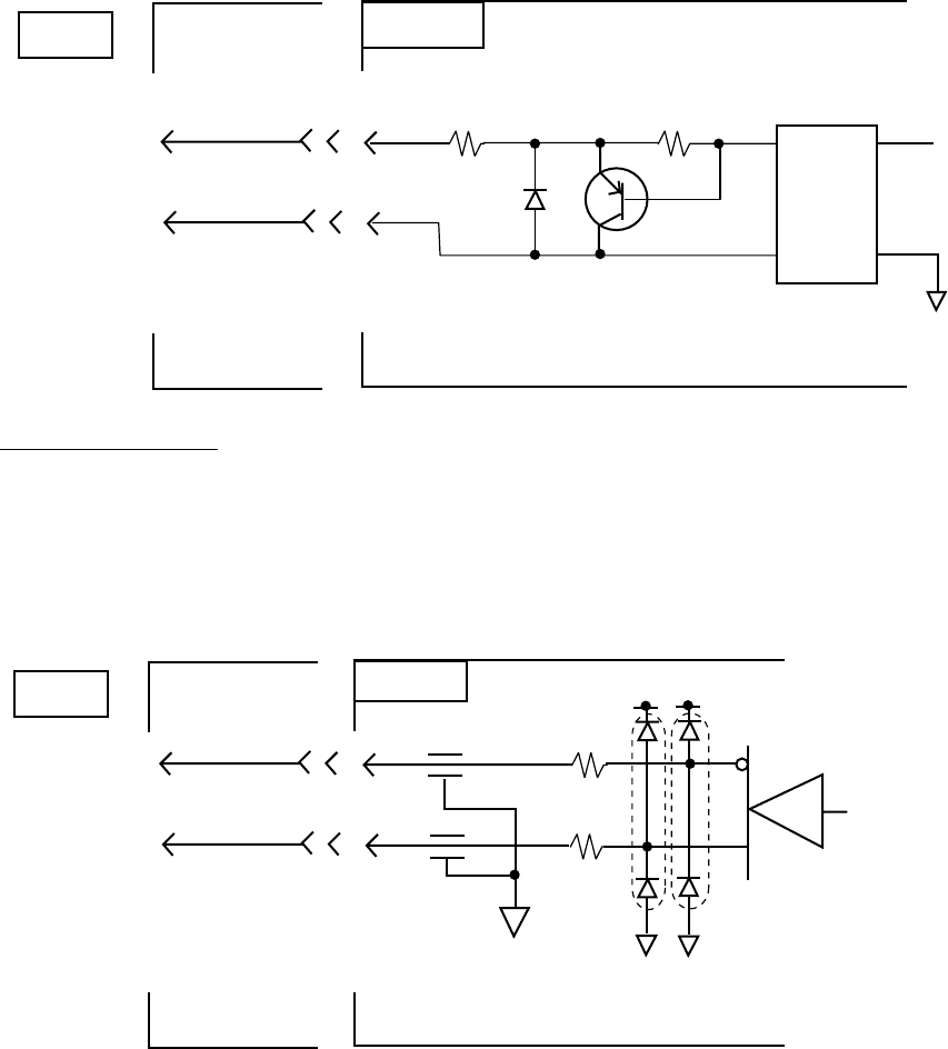
A-17
Schematic diagrams
NAV IN port (listener)
.
.
.
.
IC-212
SRCN2A16-10S 16P0148
.
.
.
.
J1
NMEA
.
..
.
RX NMEA-A 3
RX NMEA-B 4
3
4
.
.
.
.
16P1048
J1
1
3
PC-400
4
5
R58
56
R59
430
CR16
1SS355
Q1
25A1362
Load requirements
Isolation: Optocoupler
Input Impedance: 486ohm
Max. Voltage: ±15V
NAV OUT port
TX NMEA-A 1
TX NMEA-B 2
.
.
.
.
IC-212
SRCN2A16-10S 16P0148
1
2
.
.
.
.
FL2
FL1
J1
1
R63
33
R62
33
CR1 CR17
NMEA
3
2
AM26LS31CNS

AP-18
Data sentences
Input sentences
BWC - Bearing and distance to waypoint
$--BWC, hhmmss.ss, llll.ll, a yyyyy.yy, a, x.x, T, x.x, M, x.x, N, c--c, a*hh<CR><LF>
Checksum
Mode indicator
(see note 1)
Waypoint ID*
Distance, nautical miles
Bearing, degrees true
Waypoint longitude, E/W*
Bearing, degrees magnetic*
Waypoint latitude, N/S*
UTC of observation*
NOTE 1: Positioning system Mode indicator:
A = Autonomous
D = Differential
E = Estimated (dead reckoning)
M = Manual input
S = Simulator
N = Data not valid
The Mode indicator field shall not be a null field.
*: Not used
AP-19
BWR - Bearing and distance to waypoint -rhumb line
$--BWR,hhmmss.ss,llll.lll,a,yyyyy.yyy,a,x.x,T,x.x,M,x.x,N,c--c,a*hh<CR><LF>
| | | | | | | | | | | | | |
| | | | | | | | | | | | | +---- 9
| | | | | | | | | | | | +------ 8
| | | | | | | | | | | +--------- 7
| | | | | | | | | +--+------------- 6
| | | | | | | +--+------------------- 5
| | | | | +--+------------------------- 4
| | | +-----+------------------------------- 3
| +-----+------------------------------------------- 2
+---------------------------------------------------------- 1
1. UTC of observation
2. Waypoint latitude, N/S
3. Waypoint longitude, E/W
4. Bearing, degrees true
5. Bearing, degrees magnetic
6. Distance, nautical miles
7. Waypoint ID
8. Mode indicator(see note)
9. Checksum
NOTE Positioning system Mode indicator:
A = Autonomous
D = Differential
E = Estimated (dead reckoning)
M = Manual input
S = Simulator
N = Data not valid
The Mode indicator field shall not be a null field.
DBT - Depth below transducer
$--DBT,x.x,f,x.x,M,x.x,F*hh<CR><LF>
| | | | | | |
| | | | | | +--------- 4
| | | | +--+----------- 3
| | +--+----------------- 2
+--+----------------------- 1
1. Water depth, feet
2. Water depth, m
3. Water depth, fathoms
4. Checksum
AP-20
GGA - Global positioning system (GPS) fix data
$--GGA,hhmmss.ss,llll.lll,a,yyyyy.yyy,a,x,xx,x.x,x.x,M,x.x,M,x.x,xxxx*hh<CR><LF>
| | | | | | | | | | | | | | |
| | | | | | | | | | | | | | +-- 11
| | | | | | | | | | | | | +---- 10
| | | | | | | | | | | | +--------- 9
| | | | | | | | | | +---+------------ 8
| | | | | | | | +---+------------------ 7
| | | | | | | +------------------------- 6
| | | | | | +---------------------------- 5
| | | | | +------------------------------- 4
| | | +----+--------------------------------- 3
| +---+--------------------------------------------- 2
+------------------------------------------------------------- 1
1. UTC of position
2. Latitude, N/S
3. Longitude, E/W
4. GPS quality indicator (see note)
5. Number of satllite in use,00-12, may be different from the number in view
6. Horizontal dilution of precision
7. Antenna altitude above/below mean sealevel, m
8. Geoidal separation, m
9. Age of differential GPS data
10. Differential reference station ID, 0000-1023
11. Checksum
NOTE
0 = fix not available or invalid
1 = GPS SPS mode, fix valid
2 = differential GPS, SPS mode, fix valid
3 = GPS PPS mode, fix valid
4 = Real Time Kinetic. Satellite system used in RTK mode with fixed integers
5 = Float RTK. Satellite system used in RTK mode with floating fingers
6 = Estimated (dead reckoning) mode
7 = Manual input mode
8 = Simulator mode
The GPS quality indicator shall not be a null field.
AP-21
GLL - Geographic position - latitude and longitude
$--GLL,llll.lll,a,yyyyy.yyy,a,hhmmss.ss,A,a*hh<CR><LF>
| | | | | | | |
| | | | | | | +------- 6
| | | | | | +--------- 5
| | | | | +----------- 4
| | | | +---------------- 3
| | +------+----------------------- 2
+---+----------------------------------- 1
1. Latitude, N/S
2. Longitude, E/W
3. UTC of position
4. Status: A=data valid, V=data invalid
5. Mode indicator(see note)
6. Checksum
NOTE Positioning system Mode indicator:
A = Autonomous
D = Differential
E = Estimated (dead reckoning)
M = Manual input
S = Simulator
N = Data not valid
The Mode indicator field supplements the Status field. The Status field shall be
set to V=invalid for all values of Operating Mode except for A=Autonomous and
D=Differential. The positioning system Mode indicator and Status field shall not
be null fields.
MTW - Water temperature
$--MTW,x.x,C*hh<CR><LF>
| | |
| | +--------- 2
+--+----------- 1
1. Temperature, degrees C
2. Checksum
AP-22
RMA - Recommended minimum navigation information - Loran C data
$--RMA,A,llll.lll,a,yyyyy.yy,a,x.x,x.x,x.x,x.x,x.x,a,a*hh<CR><LF>
| | | | | | | | | | | | |
| | | | | | | | | | | | +------- 10
| | | | | | | | | | | +--------- 9
| | | | | | | | | +---+----------- 8
| | | | | | | | +------------------ 7
| | | | | | | +---------------------- 6
| | | | | | +-------------------------- 5
| | | | | +------------------------------ 4
| | | +----+--------------------------------- 3
| +---+-------------------------------------------- 2
+------------------------------------------------------- 1
1. Status: A=data valid, V=blink, cycle or SNR warning
2. Latitude, degrees N/S
3. Longitude, degrees E/W
4. Time difference A, microseconds
5. Time difference B, microseconds
6. Speed over ground, knots
7. Course over ground, degrees true
8. Magnetic variation(see note 1),degree E/W
9. Mode indicator(see note 2)
10. Checksum
NOTE 1 - Easterly variation(E) subtracts from true course
Westerly variation(W) adds to true course
NOTE 2 Positioning system Mode indicator:
A = Autonomous
D = Differential
E = Estimated (dead reckoning)
M = Manual input
S = Simulator
N = Data not valid
The Mode indicator field supplements the Status field. The Status field
shall be set to V=invalid for all values of Operating Mode except for
A=Autonomous and D=Differential. The positioning system Mode indicator
and Status field shall not be null fields.
AP-23
RMB - Recommended minimum navigation information
$--RMB,A,x.x,a,c--c,c--c,llll.lll,a,yyyyy.yyy,a,x.x,x.x,x.x,A,a*hh<CR><LF>
| | | | | | | | | | | | | | |
| | | | | | | | | | | | | | +--- 13
| | | | | | | | | | | | | +----- 12
| | | | | | | | | | | | +------- 11
| | | | | | | | | | | +---------- 10
| | | | | | | | | | +-------------- 9
| | | | | | | | | +------------------ 8
| | | | | | | +-----+--------------------- 7
| | | | | +----+--------------------------------- 6
| | | | +--------------------------------------------- 5
| | | +-------------------------------------------------- 4
| | +------------------------------------------------------ 3
| +--------------------------------------------------------- 2
+------------------------------------------------------------ 1
1. Data status: A=data valid, V=navigation receiver warning
2. Cross track error(see note 2) n.miles
3. Direction to steer L/R
4. Origin waypoint ID
5. Destination waypoint ID
6. Destination waypoint latitude,N/S
7. Destination waypoint longitude,E/W
8. Range to destination, n.miles(see note 1)
9. Bearing to destination, degrees true
10. Destination closing velocity, knots
11. Arrival status: A=arrival circle entered or perpendicular passed
12. Mode indicator(see note 3)
13. Checksum
NOTES
1 If range to destination exceeds 999.9 nautical miles, display 999.9.
2 If cross track error exceeds 9.99 nautical miles, display 9.99.
3 Positioning system Mode indicator:
A = Autonomous
D = Differential
S = Simulator
N = Data not valid
The Mode indicator field supplements the Status field. The Status field
shall be set to V=invalid for all values of Operating Mode except for
A=Autonomous and D=Differential. The positioning system Mode indicator
and Status field shall not be null fields.
AP-24
RMC - Recommended minimum navigation information - GPS/TRANSIT data
$--RMC,hhmmss.ss,A,llll.lll,a,yyyyy.yyy,a,x.x,x.x,xxxxxx,x.x,a,a*hh<CR><LF>
| | | | | | | | | | | | |
| | | | | | | | | | | | +--- 10
| | | | | | | | | | | +----- 9
| | | | | | | | | +--+------- 8
| | | | | | | | +--------------- 7
| | | | | | | +--------------------- 6
| | | | | | +------------------------- 5
| | | | +---+---------------------------- 4
| | +---+---------------------------------------- 3
| +--------------------------------------------------- 2
+---------------------------------------------------------- 1
1. UTC of position fix
2. Status: A=data valid, V=navigation receiver warning
3. Latitude, N/S
4. Longitude, E/W
5. Speed over ground, knots
6. Course over ground, degrees true
7. Date: dd/mm/yy
8. magnetic variation, degrees E/W
9. Mode indicator(see note)
10. Checksum
NOTE Positioning system Mode indicator:
A = Autonomous
D = Differential
E = Estimated (dead reckoning)
M = Manual input
S = Simulator
N = Data not valid
The Mode indicator field supplements the Status field. The Status field
shall be set to V=invalid for all values of Operating Mode except for
A=Autonomous and D=Differential. The positioning system Mode indicator
and Status field shall not be null fields.
VDR - Set and drift
$--VDR,x.x,T,x.x,M,x.x,N*hh<CR><LF>
| | | | | | |
| | | | | | +--------- 4
| | | | +--+----------- 3
| | +--+----------------- 2
+--+----------------------- 1
1. Direction, degrees true
2. Direction, degrees magnetic
3. Current speed, knots
4. Checksum
AP-25
VTG - Course over ground and ground speed
$--VTG,x.x,T,x.x,M,x.x,N,x.x,K,a*hh<CR><LF>
| | | | | | | | | |
| | | | | | | | | +------- 6
| | | | | | | | +--------- 5
| | | | | | +--+----------- 4
| | | | +--+----------------- 3
| | +--+----------------------- 2
+--+----------------------------- 1
1. Course over ground, degrees true
2. Course over ground, degrees magnetic
3. Speed over ground, knots
4. Speed over ground, km/h
5. Mode indicator(see note)
6. Checksum
NOTE Positioning system Mode indicator:
A = Autonomous
D = Differential
E = Estimated (dead reckoning)
M = Manual input
S = Simulator
N = Data not valid
The positioning system Mode indicator field shall not be a null field.
WPL - Waypoint location
$--WPL,llll.lll,a,yyyyy.yyy,a,c--c*hh<CR><LF>
| | | | | |
| | | | | +--------- 4
| | | | +------------ 3
| | +-----+---------------- 2
+-----+---------------------------- 1
1. Waypoint latitude, N/S
2. Waypoint longitude, E/W
3. Waypoint identifier
4. Checksum
AP-26
ZDA - Date and time
$--ZDA,hhmmss.ss,xx,xx,xxxx,xx,xx*hh<CR><LF>
| | | | | | |
| | | | | | +--------- 7
| | | | | +----------- 6
| | | | +-------------- 5
| | | +------------------ 4
| | +---------------------- 3
| +------------------------- 2
+--------------------------------- 1
1. UTC
2. Day, 01 to 31(UTC)
3. Month, 01 to 12(UTC)
4. Year(UTC)
5. Local zone hours, 00h to +-13h
6. Local zone minutes, 00 to +59
as local hours
7. Checksum
Output sentences
GGA, GLL, RMC, VTG, ZDA - See input sentences.
GSV - GNSS satellites in view
$--GSV,x,x,xx,xx,xx,xxx,xx.........,xx,xx,xxx,xx*hh<CR><LF
| | | | | | | | | | | | | |
| | | | | | | | | | | | | +--------- 10
| | | | | | | | | +--+--+---+----------- 9
| | | | | | | +-----+------------------------ 8
| | | | | | +--------------------------------- 7
| | | | | +------------------------------------- 6
| | | | +---------------------------------------- 5
| | | +------------------------------------------- 4
| | +---------------------------------------------- 3
| +------------------------------------------------- 2
+--------------------------------------------------- 1
1. Total number of messages, 1 to 9
2. Message number, 1 to 9
3. Total number of satellites in view
4. Satellite ID number
5. Elevation, ddegrees, 90deg maximum
6. Azimuth, degrees true, 000 to 359
7. SNR(C/No) 00-99 dB-Hz, null when not tracking
8. Second and third SVs
9. Fourth SV
10. Checksum
IN-1
Index
A
Address book ...................................... 2-22
Addressee code .................................... 3-2
C
Cancel transmition .............................. 4-13
Change Window ................................... 3-11
Class 1/2/3 .............................................. 10
Close ..................................................... 3-9
Combining Files ................................... 3-14
Communication network mode.............. 1-9
Communication unit remarks .............. 1-10
Communication unit status .................. 1-10
Confidential message............................ 3-2
Copy ....................................................... 3-5
Cut......................................................... 3-4
D
Date and time display........................... 1-11
Data report ............................................ 5-1
DCE version number ........................... 1-10
Delete File ........................................... 3-14
Delete message .................................... 4-25
Deliverry status .......................... 4-14, 4-16
Directories ........................................... 2-27
Display log........................................... 4-26
Display log description ........................ 4-27
Distress alert information ...................... 1-9
Distress communication ........................ 6-5
DNID ....................................................... 5-9
E
E-mail Service List .............................. 2-28
Editor menu ........................................... 3-3
EGC channels ..................................... 2-15
EGC message....................................... 4-28
EGC setup............................................ 2-11
ENID...................................................... 4-29
Entering Own Ship’s Position.............. 2-26
F
FleetNETTM ....................................... 5, 2-11
Format................................................... 3-7
Frame synchronization........................ 1-10
G
General utiltty ...................................... 4-18
I
Insert ..................................................... 3-6
IA5......................................................... 4-1
ITA2 ....................................................... 4-1
L
Land Earth Stations(LES) ......................... 7
LES List ............................................... 2-18
Log ........................................................ 4-26
Logging status...................................... 1-11
M
Maritime saftey service ....................... 4-18
Message report ....................................... 5-4
Message status list description ........... 4-15
MIME ................................................... 3-15
Mobile Earth Stations(MES) ...................... 7
N
NCS Channel ............................... 2-16, 7-4
Network Coordination Stations(NCS)........ 7
O
Ocean Region ..................................... 2-24
Ocean region receiving ....................... 1-10
Open File............................................. 3-10
Other information ................................. 1-11
P
Password .............................................. 3-2
Paste ..................................................... 3-4
Polling ................................................... 5-6
Print...................................................... 3-13
R
Receive alarm ..................................... 4-21
Distress/Urgent Receiving unit............ 4-26
Receiving ............................................ 4-20
ROM disk ............................................ 4-25
S
SafetyNETTM ............................................................ 5, 2-11
Save message ...................................... 3-8
Send status ......................................... 4-14
Ship’s position ...................................... 1-11
SPEC .................................................. 2-23
Station List ........................................... 2-22
T
Transmit message status ...................... 4-9
Two-digit code ....................................... 4-17