Futaba FDQ02T Wireless Modem with Serial Interface User Manual
Futaba Corporation Wireless Modem with Serial Interface
UserManual.wiki
>
Futaba
>
FDQ02T User Manual
Users Manual
Navigation menu
Upload a User Manual
Namespaces
Wiki Guide
HTML
PDF
Info
Views
User Manual
Discussion / Help
Navigation
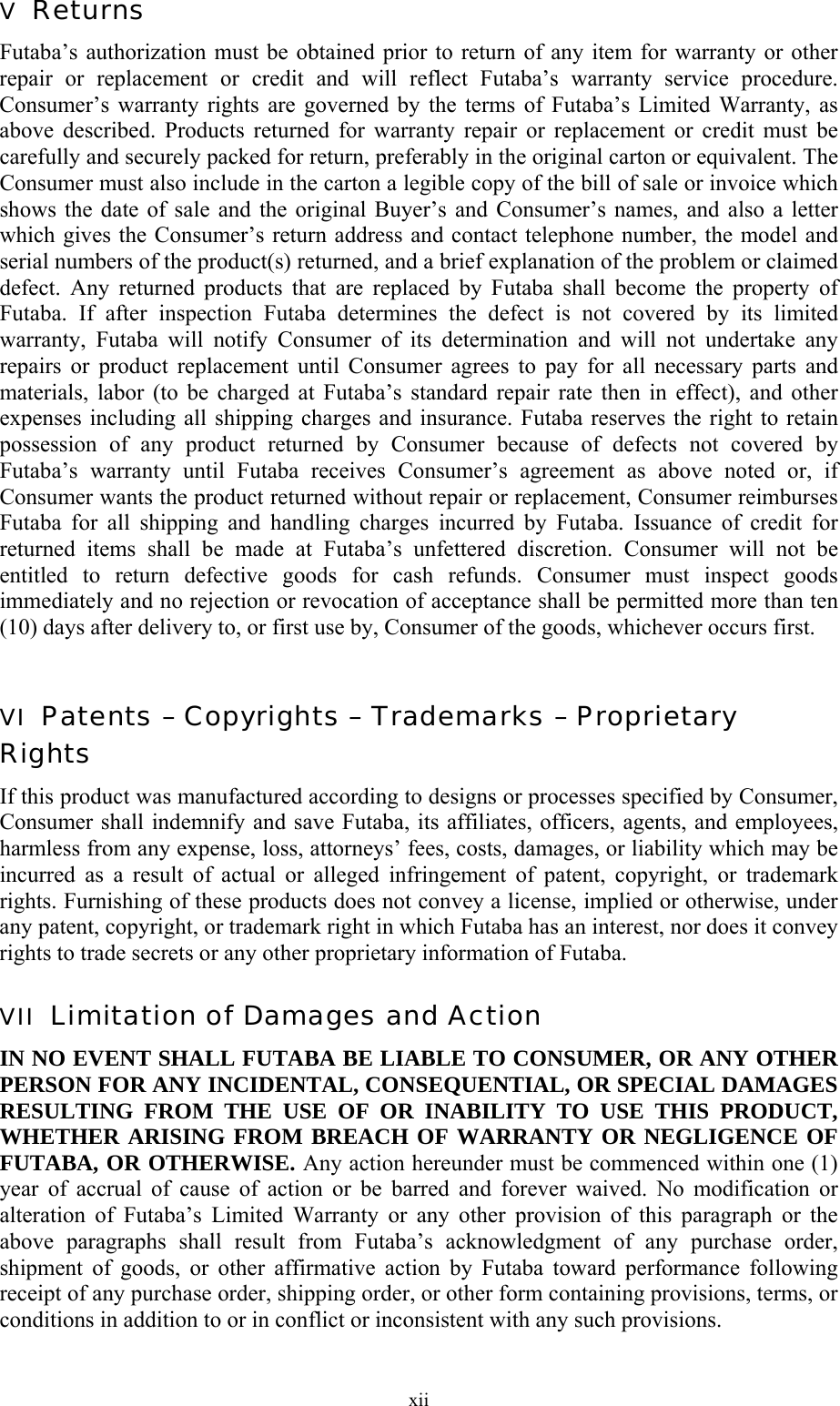

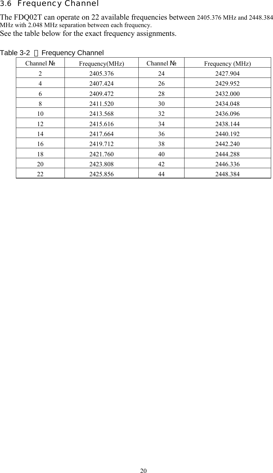
![123.1 Packet transmission mode 3.1.1 Abstract In the Packet Transmission mode, the communication is carried out by the follows procedure: (1) Once the power of the modem is turned on, the modem becomes the State for Reception. (2) The transmission command “TXT” or “TBN” makes the MODEM to the State for Transmission. (3) One transmission command can send one packet. The maximum length of the user’s message is 255 bytes for a packet. (4) Receiving a packet, the destination modem returns an “ACK” to the sender modem. Receiving the “ACK,” the sender modem ends the communication. The sender modem returns its response, which depends on the cause of success or failure in the communication. Meanwhile, the packet of a message that has failed to be transmitted will be destroyed. (5) Prior to sending messages consecutively, the modem checks the responses whether the previous transmission has been successful or not. (6) The modem returns to the State for Reception after finishing the transmission. 3.1.2 T Transmission command and reception header The transmission commands used for the Packet Transmission mode are “TXT”, “TXR”, “TBN” or “TBR.” Depending on the transmission commands, there are four different formats that are used to output received data to external equipment. The external equipment can find the data format by its reception deader. Table 3-1:Transmission command and reception header Transmission command Reception header Function TXT RXT Transmit text data TXR RXR Transmit text data via repeater TBN RBN Transmit binary data TBR RBR Transmit binary data via repeater The followings are the input format of transmission data from the external equipment to the modem and the reception format from the modem to the external equipment. (1) Text data transmission Transmission : @TXT[destination address] [message] [CRLF] Example : @TXT012HELLO [CRLF] Reception : RXT[sender address] [message] [CRLF] The “TXR” and “TBR” commands via repeater are not utilized for the modem, but are explained here for the future upgrade.](https://usermanual.wiki/Futaba/FDQ02T/User-Guide-662360-Page-26.png)
![13Example : RXT0015HELLO [CRLF] (2) Text data transmission via repeater Transmission : @TXT[repeater address] [destination address][message][CRLF] Example : @TXT003012HELLO [CRLF] Reception : RXT[repeater address] [sender address][message][CRLF] Example : RXT003015HELLO [CRLF] (3) Binary data transmission Transmission : @TBN[destination address] [the number of bytes of the message] [message] [CRLF] Example : @TBN012005HELLO [CRLF] Reception : RBN[sender address] [the number of bytes of the message] [message] [CRLF] Example : RBN015005HELLO [CRLF] (4) Binary data transmission via repeater Transmission : @TBN[repeater address] [destination address] [the number of bytes of the message] [message] [CRLF] Example : @TBN003012005HELLO [CRLF] Reception : RBN[repeater address] [destination address] [the number of bytes of the message] [message] [CRLF] Example : RBN003015005HELLO [CRLF] 3.1.3 Broadcast communication If the destination address is set to 255, the sender modem broadcasts to all the other modems, which is called broadcast communication. In the broadcast communication, the sender modem can transmit its data to multiple modems simultaneously. However, the modem cannot determine whether all the other modems have received the data without a failure because ACK is not returned from any of them in the broadcast communication. In the broadcast communication, the sender modem repeats retransmission inevitably up to the predetermined count and then returns an “end” response to its external equipment. Meanwhile, if the receiver modems have received data properly, the modems output the data to their external equipment. However, the modems do not output the retransmitted data to their external equipment if the data has been once accepted properly.](https://usermanual.wiki/Futaba/FDQ02T/User-Guide-662360-Page-27.png)
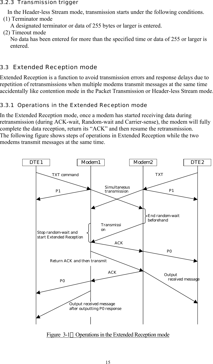
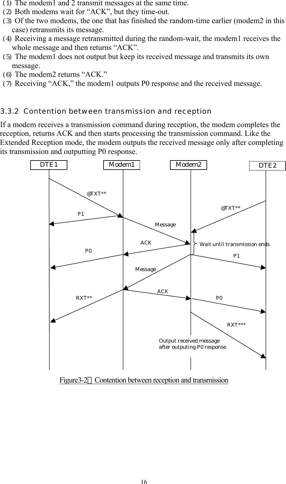
![143.2 Header-less Stream mode 3.2.1 Abstract The Header-less Stream mode, a special Packet Transmission mode, does not require the procedures for transmission commands that are necessary in the Packet Transmission mode, but requires only inputting transmission data directly. (1) The destination address can be set in memory register or by command. (2) The transmission triggers such as terminator, timeout and a specified number of bytes can be set in the memory register. (3) The maximum length of the message in a packet is 255 bytes , and the number is including terminator. (4) Receiving a packet, the destination modem returns an ”ACK” to sender modem. Receiving the “ACK,” the sender modem ends the communication. (5) The sender modem does not return any response regardless of success or failure in the communication. It is necessary for application software to checking the establishment of the communication. (6) Since the modem has a transmission buffer inside, you can enter transmission data consecutively without waiting the end of transmission like in the Packet Transmission mode. (7) This mode is compatible and can communicate with the Packet Transmission mode. 3.2.2 Format The Header-less Stream mode does not out put the responses such as P1, P0 and N1 in response to transmission commands. In addition, it doesn’t output the reception header or CRLF code, which is used in the Packet Transmission mode, but outputs instead special characters (terminators), which are used as packet separators, as part of data. The followings are the transmission and reception formats in the Header-less Stream mode. 1.Packet Transmission mode(Reference) Transmission : @TXT002HELLO [CRLF] Reception : RXT001HELLO [CRLF] 2.Header-less Stream mode (When terminator is CRLF.) Transmission : HELLO [CRLF] Reception : HELLO [CRLF] 3.Transmission in the Header-less Stream mode, Reception in the Packet Transmission mode(text mode) Transmission : HELLO [CRLF] Reception : RXT001HELLO [CRLF] [CRLF] 4.Transmission in the Header-less Stream mode, Reception in the Packet Transmission mode(binary mode) Transmission : HELLO [CRLF] Reception : RBN001007HELLO [CRLF] [CRLF] 5.Transmission in the Packet Transmission mode, Reception in the Header-less Stream mode Transmission : @TXT002HELLO [CRLF] Reception : HELLO](https://usermanual.wiki/Futaba/FDQ02T/User-Guide-662360-Page-28.png)
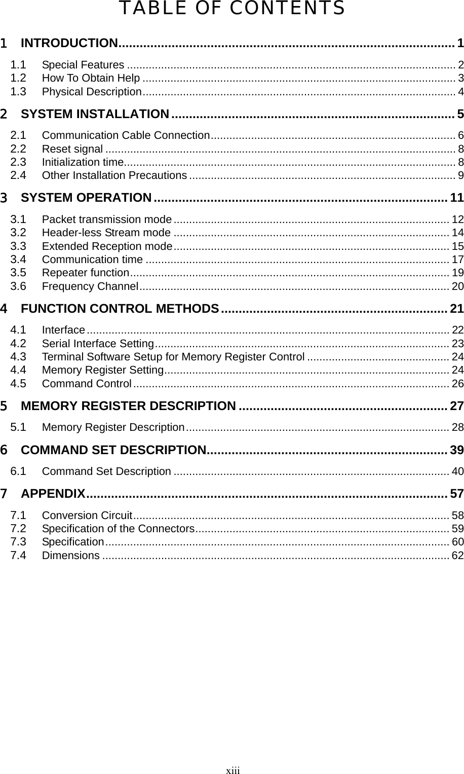
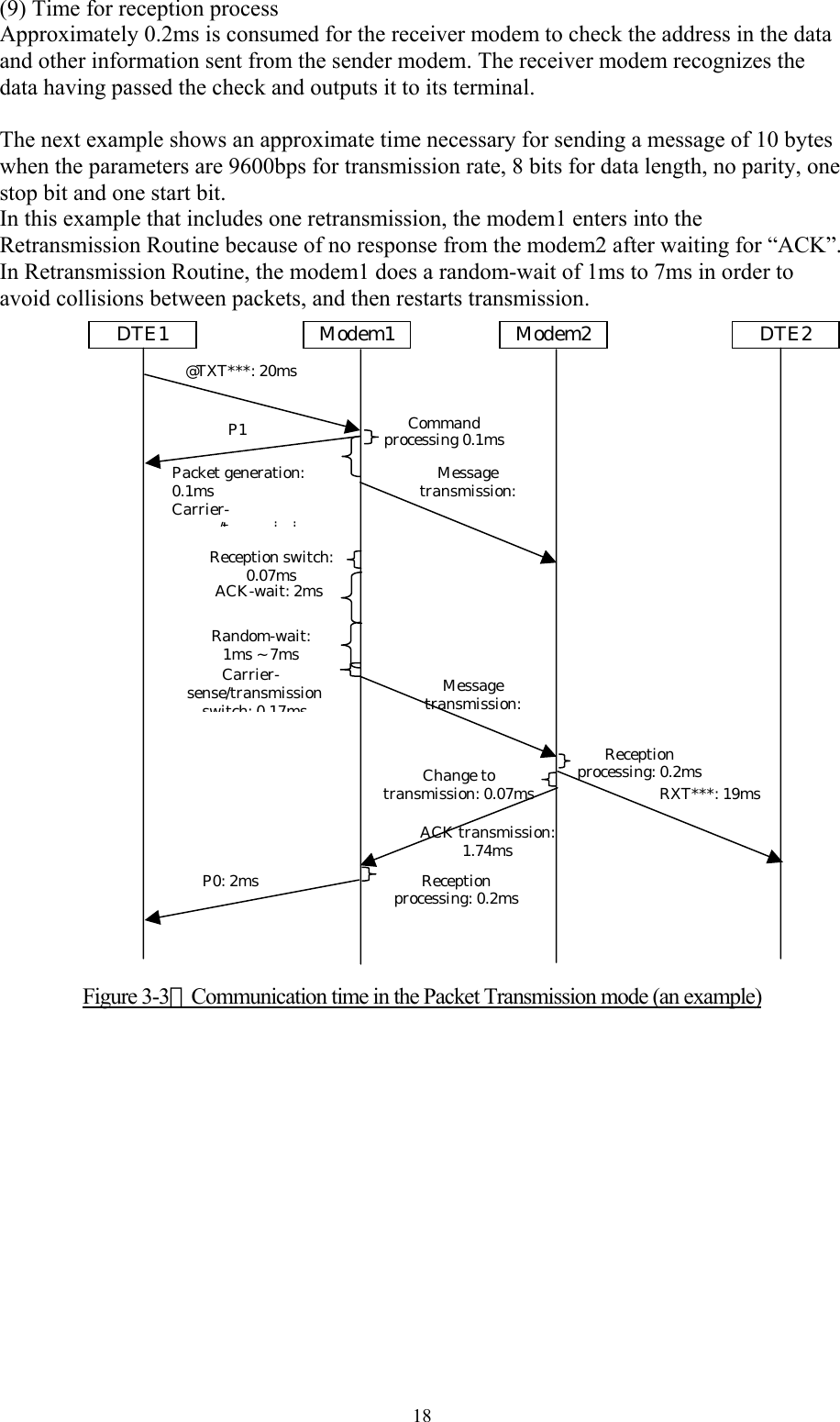
![173.4 Communication time The time consumed for each communication sequence in the Packet Transmission mode is as follows. (1) Time for entering a transmission command The time consumed for entering a transmission command to the modem from its terminal depends on the communication parameters between them. Parameters are: 1.Transmission rate (300ps to 115.2kbps) 2. Data length (7 or 8 bits) 3. Parity bit (yes or none) 4. Stop-bit length (one or two bits) 5. Start-bit length (one bit) For example, in the case of 9600bps for transmission rate, 8 bits for data length, no parity, one stop bit and one start bit, the time consumed for sending one bit will be 104µs. And the time for sending the data of a byte that consists of 10 bits will be 1.04ms. In the case of sending a message data of ten bytes by “TXT” command, the time consumed for sending the message will be 19.8ms because the transmission format becomes “@TXT001ABCDEFGHIJ [CRLF]”, which is 19 bytes. (2) Time to generate a transmission packet The internal processing time to generate a transmission packet after accepting a command is 1ms or less even though the length of the message data varies from 1 to 255 bytes. In the Header-less Stream mode, it takes 2ms or less. (3) Time for carrier sense Prior to transmission, the modem checks SS correlation. If any SS correlation is detected within 0.1ms, the modem does not transmit any data. (4) Time to switch between transmission and reception The internal processing time consumed for switching transmission to reception or vice versa is approximately 0.07ms. (5) Transmission time via radio Depending on the number of bytes of a message data (1 to 255), the time consumed to transmit the message is obtained from the following calculation. 1.74ms + (the number of bytes in the message) × 0.06ms (6) Waiting time for “ACK” This is the time consumed for waiting for “ACK” after completing transmission via radio. The waiting time is 2ms. The modem determines that the transmission has failed if it could not receive “ACK” packet in that period of time. Then the modem waits for the random-wait time and then repeats the above steps starting from the carrier sense if the number of retransmissions has not reached the predetermined number. If there is no remaining number of retransmissions, the modem ends its transmission, outputting the response of “transmission failure”. (7) Time to transmit “ACK” or “NAK” The time consumed for transmitting “ACK” or “NAK” is 1.74ms. (8) Time for random-wait When SS correlation has been detected by carrier sense, or when retransmission is required due to the transmission failure, carrier sense will start only after waiting for the random time in order to avoid collisions between packets. The time for random-wait is from 1ms to 7ms.](https://usermanual.wiki/Futaba/FDQ02T/User-Guide-662360-Page-31.png)
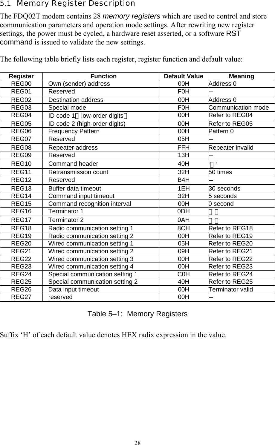
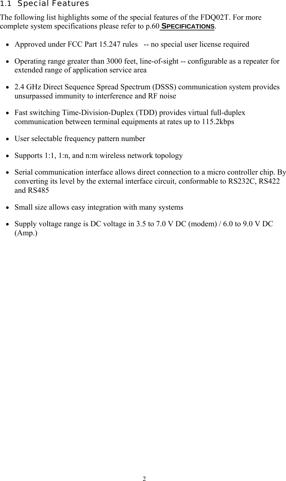
![29REG00: Own (sender) address [default value: 000] • This register is used to set the address of a modem. Valid values are from 000 to 254. • The value in this register is used as a sender address in every data packet being sent. • When the address-check function is used, it is possible to receive a packet if the packet contains such value as a destination address. REG01: Reserved [default value: 240] • The FDQ02T does not use this register. Keep the default value as it is. REG02: Destination Address [default value: 000] • In the Header-less Stream mode, this register is used to set the address of a destination modem. Valid values are from 000 to 255. • This destination address is attached to every data packet to be sent. • When using the address-check function, set the destination address in this register. When using the “DAS” command, however, the address defined by the “DAS” command is always prioritized. • The destination address 255 represents the broadcast communication. REG03: Special mode [default value: F0H] • This register is used to set a special operating mode. The default is the Communication mode. REG04: ID Code 1 [default value: 00H] • Used with ID code 2 (REG05), set the ID code. Valid values are 000 to 255. Together with ID code 2, up to 65535 ID codes can be set. • The ID code identifies the group of the modems works in the same group. The ID code is used to prevent erroneous connection with other systems and for communication security. • Before transmission, radio data packets are scrambled using a pseudo-random data sequence generated with this ID code as the seed. During reception, the original data is restored by de-scrambling it with the pseudo-random data sequence. The modems with different ID codes cannot communicate with each other. REG05: ID Code 2 [default value: 00H] • Used with ID code 1 (REG04), set the ID code. Valid values are 000 to 255. Together with ID code 1, up to 65535 ID codes can be set. • In case plural modems are used as a single system, always set the same ID code for all modems and repeaters.](https://usermanual.wiki/Futaba/FDQ02T/User-Guide-662360-Page-43.png)
![30REG06: Frequency pattern [default value:00H] • This register is used to set a frequency pattern. The valid values are from 00H to 15H. • To establish communication in a system, the same frequency pattern should be used. In contrast, to let multiple systems operate in the same area, each system should have different frequency patterns. • When using multiple systems in the same area, frequencies may periodically match and interfere with each other even if the systems are using different frequency patterns. REG07: Reserved [default value: 05H] • The FDQ02T does not use this register. Keep the default value as it is. REG08: Repeater Address [default value: FFH] • This register is used to set repeater address when using repeater in the Header-less Stream mode. • When not using repeater, set “FFH” at this register, making the communication direct. REG09: Reserved [default value: 13H] • The FDQ02T does not use this register. Keep the default value as it is. REG10: Command Header [default value: 40H] • Sets the character that identifies the start of a command. • The default is character “@” (40H). • When this character is input from the terminal equipment after no character is received for the command recognition interval (REG15) or longer, subsequent input character is recognized as a command for the modem. REG11: Retransmission Count [default value: 32H] • Sets the maximum number of packet retransmission attempts. Valid values are 000 to 255. • When retransmission exceeds the retransmission count (retransmission count plus one), the modem outputs an error response to the terminal equipment. REG12: Reserved [default value: B4H] • The FDQ02T does not use this register. Keep the default value as it is.](https://usermanual.wiki/Futaba/FDQ02T/User-Guide-662360-Page-44.png)
![31REG13: Buffer Data Timeout [default value: 1EH] • This register is used to set the waiting time to clear the content of the buffer after the last change in the buffer. • Valid values are from 000 to 255 seconds with an increment of 1 second. The default value is 30 seconds. • If the Buffer Data Timeout is not necessary, set it at “0.” • This value should be longer than the Data Input timeout (REG26). REG14: Command Input Timeout [default value: 32H] • Sets the character input timeout interval for command input. It is used as the timeout between the command header and the character following it and between each character of the command. • At the timeout, the modem operation transits from command-input-state to data-wait-state. • Valid values are 000 to 255, representing tenths of seconds in 0.1 second increments. (Set an integer value equal to ten times the number of seconds desired.) • A setting of 000 disables this timeout function REG15: Command Recognition Interval [default value: 00H] • When a message data contains a command header character (in case of binary data or data in two-byte Chinese characters), data following the command header character will be interpreted as a command, the message does not transmit properly. • Sets the necessary vacant duration time interval to discriminate between ordinary data character and a command header character. Input a command after a longer interval than time interval setting. • Valid values are 0.1 to 25.4 sec., representing tenths of seconds in 0.1 second increments. (Set an integer value equal to ten times the number of seconds desired.) • When set to 000, the command header is recognized at any time, and when set to 255, all command header character are ignored. REG16: Terminator 1 [default value: 0DH] • Set an arbitrary 1 byte terminator. In case of a 2-byte terminator, set the first byte character of the terminator. REG17: Terminator 2 [default value: 0AH] • Set another arbitrary 1 byte terminator. In case of a 2-byte terminator, set the last character of the terminator .](https://usermanual.wiki/Futaba/FDQ02T/User-Guide-662360-Page-45.png)
![32REG18: Communication Setting 1 [default value: 8CH] Bits 7 – 6: Protocol bit 7 bit 6 Setting 0 0 Data transpalent mode 0 1 Reserved 1 0 Packet transmission mode 1 1 Headerless stream mode Table 5–7: Protocol Bits 5: Reserved • The FDQ02T does not use this register. Keep the default value as it is. Bit 4 Transmission format 0 transmit in the text form (default value) 1 transmit in the binary form Table 7–4 Transmission format • Selects the transmission format. When data are transmitted to the destination station which is set to the normal packet transmission mode, output text format (RXT, RBN) from the receiver modem (destination station) differs depend on this setting. • This setting does not effect in the receiver modem set as headerless stream mode. Bits 3 – 2 Terminator Setting bit 3 bit 2 setting 0 0 two kinds of arbitrary 1 byte code (REG16, REG17) 0 1 arbitrary 1 byte code (REG16) + a wild card (any character) 1 0 arbitrary 2 byte code (REG16 + REG17) 1 1 carriage return (CR) + line feed (LF) (default value) Table 7–5 Terminator setting • Sets the terminator to identify the breakpoint of a packet. The modem transmits data considering this character as the breakpoint of a packet. • In case of using an arbitrary terminator, set it to REG16 and 17. Bit 1: Source address check 0 Inhibit source address checking (default value) 1 Activate source address checking Table 5–4: Source Address Check Settings](https://usermanual.wiki/Futaba/FDQ02T/User-Guide-662360-Page-46.png)
![33• When the source address checking is active and the source address in the received packet header does not match the destination address setting (REG02), the data is discarded (data cannot be received). Bit 0: Destination address check 0 Inhibit destination address checking on receipt (default) 1 Activate destination address checking on receipt Table 5–5: Destination address check • When the destination address checking is active and the destination address in the received packet header does not match the received modem’s local station address (REG00), the data is discarded (data cannot be received). REG19: Communication Setting 2 [default value: 00H] Bit 7 - 6: Reserved • The FDQ02T does not use this register. Keep the default value as it is. Bit 5: Broadcast Reception 0 Enable broadcast transmission reception (default value) 1 Disable broadcast transmission reception Table 5–7: Broadcast Reception Settings • Enable/disable reception of broadcast transmission in packet transmission mode (Mode 3 and 5). Bit 4 - 2: Reserved • The FDQ02T does not use this register. Keep the default value as it is. Bit 1: Master/Slave 0 Slave station (default) 1 Master station Table 5–11: Master/Slave • There should be no more or no less than one master station among a group of modems that communicate each other. The number of slave stations can be up to the number defined by the REG00. (253 Max) • The master station transmits beacon as a reference. Bit 0: Reserved • The FDQ02T does not use this register. Keep the default value as it is.](https://usermanual.wiki/Futaba/FDQ02T/User-Guide-662360-Page-47.png)
![34REG20: Wired communication Setting 1 [default value: 05H] Bit 7: Data Length 0 8 bit data bytes (default value) 1 7 bit data bytes Table 5–13: Data Length Settings Bit 6: Parity Bit 0 No parity bit (default value) 1 Parity bit Table 5–14: Parity Settings Bit 5: Even/Odd Parity 0 Even parity (default value) 1 Odd parity Table 5–15: Odd/Even Parity Settings • Invalid when bit 6 is set to 0, without parity. Bit 4: Stop Bit 0 1 stop bit (default value) 1 2 stop bits Table 5–16: Stop Bit Settings Bits 3 – 0: Baud rate setting Bit 3 Bit 2 Bit 1 Bit 0 Setting 0 0 0 0 300 bps 0 0 0 1 600 bps 0 0 1 0 1200 bps 0 0 1 1 2400 bps 0 1 0 0 4800 bps 0 1 0 1 9600 bps (default) 0 1 1 0 19200 bps 0 1 1 1 38400 bps 1 0 0 0 Reserved 1 0 0 1 Reserved 1 0 1 0 Reserved 1 0 1 1 Reserved 1 1 0 0 57600 bps 1 1 0 1 115200 bps 1 1 1 0 Reserved 1 1 1 1 Reserved Table 5–17: Baud Rate](https://usermanual.wiki/Futaba/FDQ02T/User-Guide-662360-Page-48.png)
![35REG21: Wired communication Setting 2 [default value: 09H] Bits 7 – 5: Reserved • The FDQ02T does not use this register. Keep the default value as it is. Bit 4: Command Header 0 Use REG 10 character 1 Use Break signal Table 5–16: Command Header Bit 3 - 2: Reserved • The FDQ02T does not use this register. Keep the default value as it is. Bit 1: Flow Control 0 Software flow control (default value) 1 Hardware flow control Table 5–18 Software/Hardware Flow Control Settings • Selects the flow control method. This setting must match the connected terminal equipment’s setting. • Hardware flow control uses the two control lines RTS and CTS. When using with the RS485 interface, be sure to set to 0. • Software flow control uses XON and XOFF codes. Bit 0: Reserved • The FDQ02T does not use this register. Keep the default value as it is. REG22: Wired communication Setting 3 [default value: 00H] Bit 7: Enable and Disable Reception 0 Enable reception at the initial state (default value) 1 Disable reception at the initial state Table 5–19: Enable/Disable Reception • The initial state is in reception enable. Depending on an usage of the modem, the initial state of the modem may be better in the reception disable state. In such a case, use this setting. • Issue the REN command to enable reception. Bit 6 - 0: Reserved • The FDQ02T does not use this register. Keep the default value as it is.](https://usermanual.wiki/Futaba/FDQ02T/User-Guide-662360-Page-49.png)
![36REG23: Wired communication Setting 4 [default value: 00H] Bit 7 - 5: Reserved • The FDQ02T does not use this register. Keep the default value as it is. Bit 4 : CR/LF addition/deletion (1) Setting at the headerless stream mode 0 does not add CR/LF code to the received data (default value) 1 adds CR/LF code to the received data Table 7–6: Addition of CR/LF code • In the headerless stream mode, setting is made whether the CR/LF character is added to the received data or not. • In the communication between the modems set to the headerless packet mode, this setting is invalid because the terminator is originally added to the transmit data. However, when a packet is received from the modem in the packet transmission mode, there is no addition of the CR/LF terminator. In this case, set this bit to 1. Then the received packet is output with the CR/LF character is added. (2) Setting at the packet transmission mode 0 adds the CR/LF to the received data (default value) 1 does not add the CR/LF to the received data Table 7–7: Deletion of CR/LF character • In the packet transmission mode, setting is made whether the CR/LF character is added to the received data or not. • At the receiver modem (set to the packet transmission mode), the sender (set to the headerless stream mode) side terminator (CR/LF character as default) plus packet transmission mode terminator (CR/LF) are output. To avoid such redundant outputs, set this bit of the modem in the normal packet transmission mode to 1. Bit 3 - 0: Reserved • The FDQ02T does not use this register. Keep the default value as it is.](https://usermanual.wiki/Futaba/FDQ02T/User-Guide-662360-Page-50.png)
![37REG24: Reserved [default value: C0H] • The FDQ02T does not use this register. Keep the default value as it is. REG25: Reserved [default value: 40H] • The FDQ02T does not use this register. Keep the default value as it is. REG26: Data input timeout [default value: 00H] • Sets the vacant duration time interval to recognize as the end of the message data input in the headerless stream mode. REG27: Reserved [default value: 00H] • The FDQ02T does not use this register. Keep the default value as it is.](https://usermanual.wiki/Futaba/FDQ02T/User-Guide-662360-Page-51.png)
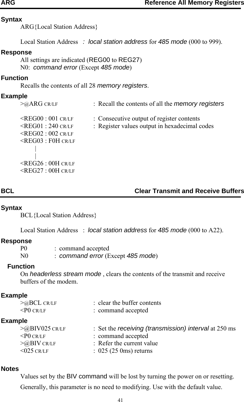
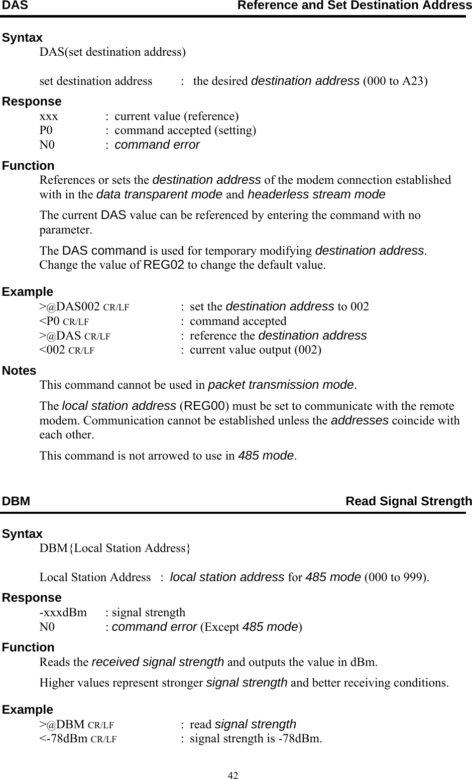
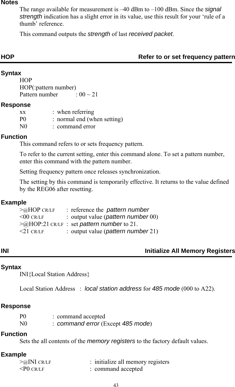
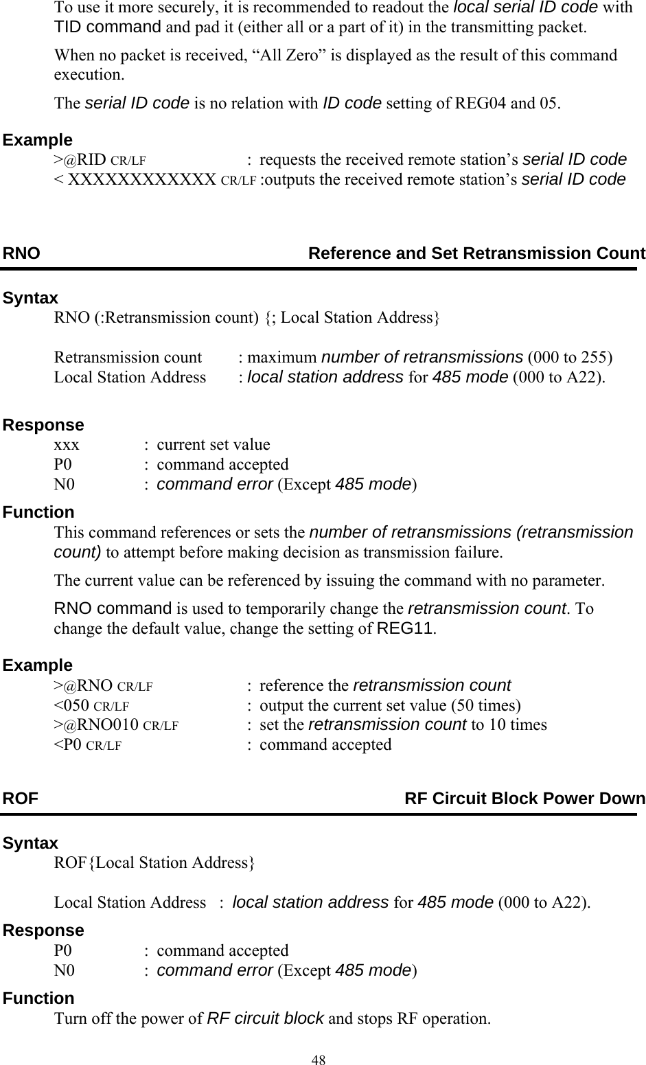
![406.1 Command Set Description This section provides a description of each command available in the FDL command set. The table below lists each command and it applicability in each operation mode. Command Function 1 ARG Reference All Memory Resisters 2 BCL Clear Transmit and Receive Buffers 3 DAS Reference and Set the Destination Address 4 DBM Read Signal Strength 5 HOP Refer to or set frequency pattern 6 INI Initialize All Memory Resisters 7 ODA Disable Received Data Output 8 OEN Enable Received Data Output 9 PAS Reference and Set Repeater Address 10 RDA Disable Wireless Reception 11 REG Reference and Set Memory Resisters 12 REN Enable Wireless Reception 13 RID Display Received Serial ID 14 RNO Reference and Set Retransmission Count 15 ROF RF Circuit Block Power Down 16 RON RF Circuit Block Power Up 17 RST Reset 18 SAS Reference and Set Local Station Address 19 STS Read Status 20 TBN Transmit Binary Data 21 TBR Transmit Binary Data Through Repeater 22 TID Display Local Station Serial ID 23 TS2 Test radio link 24 TXR Transmit Text Data Through Repeater 25 TXT Transmit Text Data 26 VER Reference Version Information Table 6–1: Command to Mode Availability The symbols used in this section have the following meaning: > : Input character from the terminal equipment to the modem < : Output from the modem to the terminal equipment @ : Command header CR/LF : Terminator (carriage return + line feed) [ ] : Required input parameter/s Be sure to input. ( ) : Optional input parameter/s May be omitted {} : 485 mode local station address (REG00). Be sure to input at 485 mode In the Syntax and Response segments of the following command descriptions the terminator symbol (CR/LF) has been omitted for clarity.](https://usermanual.wiki/Futaba/FDQ02T/User-Guide-662360-Page-54.png)
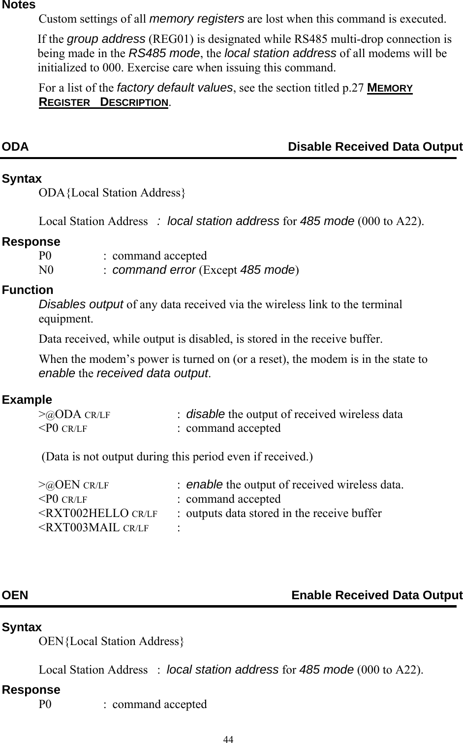
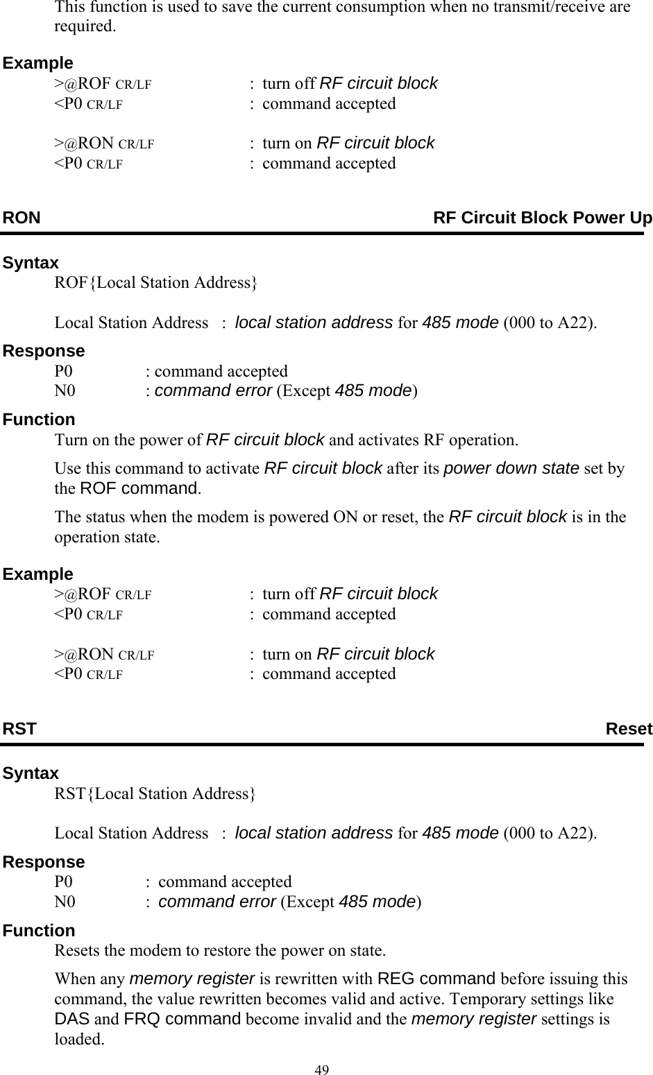
 {;Local Station Address} register number : register number to be set (00 to 27) value : value to be set. Input 2 hexadecimal digits (0 through 9 and A through F) followed by the number radix designator H. Local Station Address : local station address for 485 mode (000 to A22 ). Response xxx : current value (reference) P0 : command accepted (setting) N0 : command error (Except 485 mode) N6 : memory register write error Function References or sets memory registers. The current register value is referenced by omitting the “value” parameter. Example >@REG00 CR/LF : reference the contents of register 00 <01H CR/LF : displays current value >@REG00 : 023 CR/LF : set value of memory register 00 to 023 (decimal) <P0 CR/LF : command accepted Notes The register can be rewritten sequentially. However, to make its parameter valid after rewriting it, re-supply the power, reset the modem or use RST command.](https://usermanual.wiki/Futaba/FDQ02T/User-Guide-662360-Page-60.png)
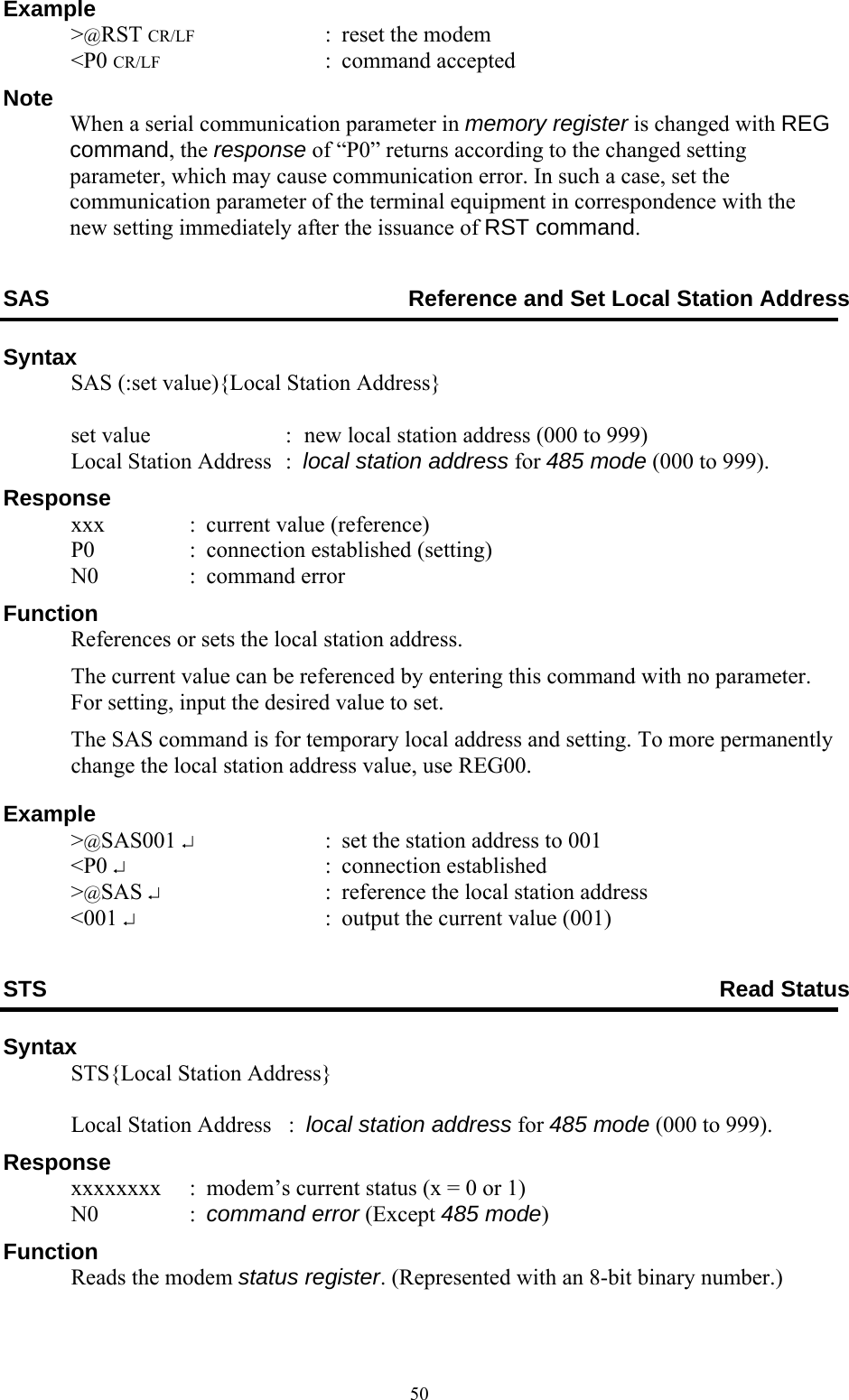
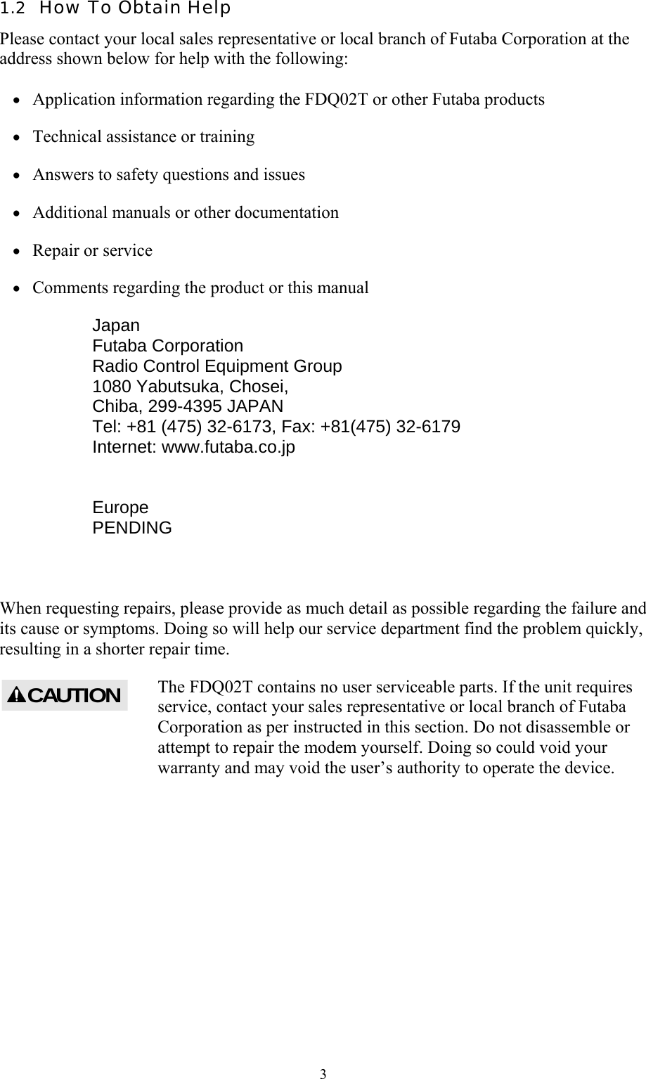
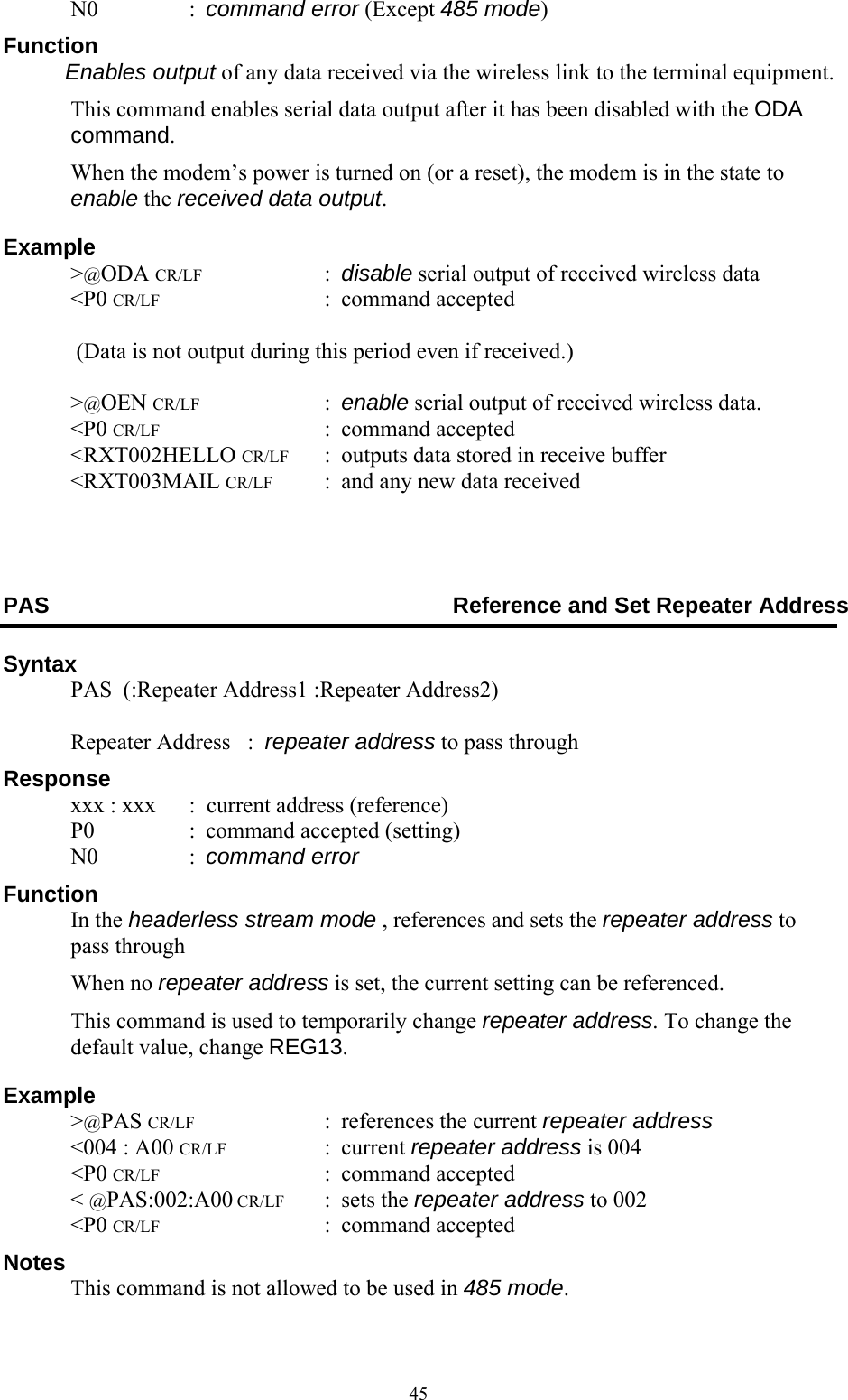
![51X X X X X X X X Status Bit Name 1 0 0 Connection Connected Disconnected1 Reception Disabled Enabled 2 Output message Disabled Enabled 3 Receive buffer Data exist Data empty 4 Transmit buffer Data exist Data empty 5 Reserved - - 6 Reserved - - 7 Reserved - - Figure 6–2: Modem Status Bit Description Example >@STS CR/LF : read the current status <00001010 CR/LF : Received data exist, Output message enabled, Reseption disabled ,Disconnected. TBN Transmit Binary Data Syntax TBN[destination address][message byte length]{Local Station Address}[message] Destination address : address of the transmission (000 to A23) Message byte length : message length (001 to 255) Local Station Address : local station address for 485 mode (000 to A22). Message byte : arbitrary binary data (255 or less) Response P0 : data transmission succeeded P1 : command accepted, data being transmitted N0 : command error (Except 485 mode) N1 : data transmission failed -- no response from destination station N2 : data transmission failed -- destination station is in the reception disabled state N3 : data transmission failed -- destination station cannot receive because its receive buffer is full Function Transmits binary data in the packet transmission mode. Any message length between 1 to 255 bytes is accepted. The modem counts the number of message characters and transmits the message. For broadcasting messages to multiple modems, set the destination address to 255. In this case, the modem retransmits the message the number of times of the Retransmission count plus 1, and then it will return “P0”. In case the global addressing command is issued to plural modems connected by RS485 multi-dropping interface, the transmission stops when any modem outputs “P0”, “N2” or “N3” response to the RS485 line. Example >TBN002005HELLO CR/LF : transmit “HELLO” from station 001 to station 002 <P1 CR/LF : data being transmitted <P0 CR/LF : data transmission succeeded. >@TBN003004MAIL CR/LF : retransmit “MAIL” from station 001 to station 003](https://usermanual.wiki/Futaba/FDQ02T/User-Guide-662360-Page-65.png)
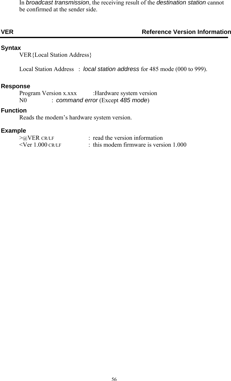
![52 <P1 CR/LF : data being transmitted <N1 CR/LF : transmission failed, no response from destination station Notes Set the message length to 255 byte or less. The message length exceeding 255 byte will be command error. Message must be terminated with 2 byte (CR/LF) character, others will be command error. In broadcast transmission, the receiving result of the destination station cannot be confirmed at the sender side. TBR Transmit Binary Data through Repeater Syntax TBR [repeater address] [destination address] [message byte length]{Local Station Address}[message] Repeater address : repeater address to pass through (000 to 999) Destination address : address of destination station (000 to A23) Message byte length : message byte length (001 to 255) Local Station Address : local station address for 485 mode (000 to A22). Message byte : arbitrary binary data (255 or less) Response P0 : data transmission succeeded P1 : command accepted, data being transmitted P2 : data packet reached to repeater N0 : command error (Except 485 mode) N1 : data transmission failed -- no response from destination station N2 : data transmission failed -- destination station is in the reception disabled state N3 : data transmission failed -- destination station cannot receive because its receive buffer is full Function In the packet transmission mode, transmits binary data through repeater. Any message length between 1 to 255 bytes is accepted. The modem counts the number of message characters and transmits the message. For broadcasting messages to multiple modems, set the destination address to 255. In this case, the modem retransmits the message the number of times of the Retransmission count plus 1, and then it will return “P0”. In case the global addressing command is issued to plural modems connected by RS485 multi-dropping interface, the transmission stops when any modem outputs “P0”, “N2” or “N3” response to the RS485 line. Example >TBR100002005HELLO CR/LF : transmit “HELLO” from station 001 to station 002 <P1 CR/LF : data being transmitted <P2 CR/LF : data packet reached to repeater <P0 CR/LF : data transmission succeeded Notes Set the message length to 255 byte or less. The message length exceeding 255 byte will be command error. Message must be terminated with 2 byte (CR/LF) character, others will be command error. In broadcast transmission, the receiving result of the destination station cannot be confirmed at the sender side.](https://usermanual.wiki/Futaba/FDQ02T/User-Guide-662360-Page-66.png)
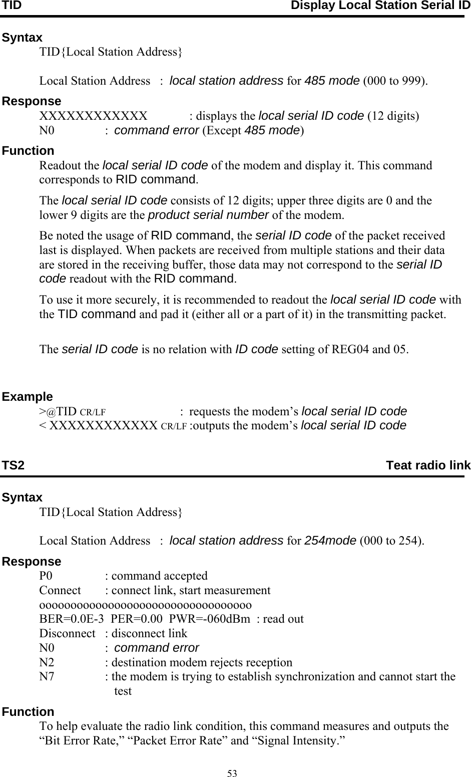
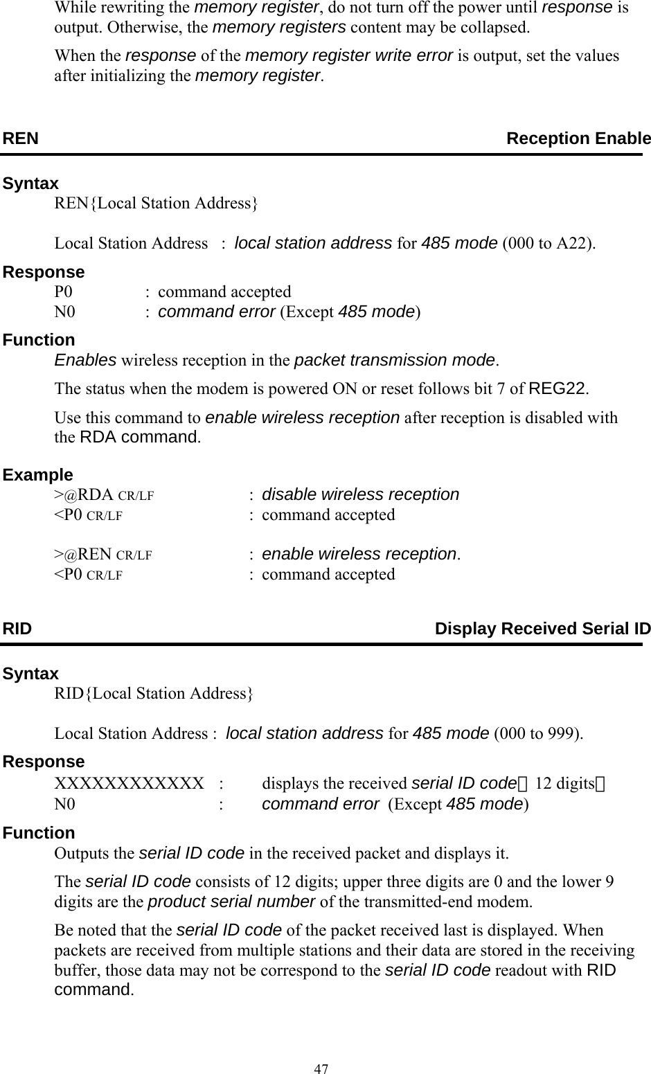
![54The command accompanying a destination address requests a connection to the destination address. The command without a destination address requests a connection to the address defined by the DAS command. The modem that has received a connection request starts actions of the TS2 immediately. The modem to which the command is entered is called “TS2 master.” The destination modem is called “TS2 slave.” The TS2 slave does not output any measurement results. Ten-consecutive failures in reception disconnect the radio link. Meanwhile, the TS2 master keeps outputting connection request. The TS2 master modem renews the measurement result approximately every 0.27second and continues outputting the measurement results until the TS2 command is terminated. To stop measurement, enter the command “RST” or turn off the modem. The radio modem, being turned into a special mode by this TS2 command, may output command error or irrelevant responses against all commands except RST command. The TS2 command always conducts “address check.” TXR Transmit Text Data through Repeater Syntax TXR [repeater address] [destination address]{Local Station Address}[message] repeater address : address of repeater to pass through (000 to 999) destination address : address of destination station (000 to A23) Local Station Address : local station address for 485 mode (000 to A22). message : any text data (255 or less) Response P0 : data transmission succeeded P1 : command accepted, data being transmitted P2 : data packet reached to repeater N0 : command error (Except 485 mode) N1 : data transmission failed -- no response from the destination station N2 : data transmission failed -- destination station is in the reception disabled state N3 : data transmission failed -- destination station cannot receive because its receive buffer is full. Function Transmits text data in the packet transmission mode through repeater. Any message length between 1 to 255 bytes is accepted. The completion of data input is recognized by the terminator. For broadcasting messages to multiple modems, set the destination address to 255. In this case, the modem retransmits the message the number of times of the Retransmission count plus 1, and then it will return “P0”. In case the global addressing command is issued to plural modems connected by RS485 multi-dropping interface, the transmission stops when any modem outputs “P0”, “N2” or “N3” response to the RS485 line. Example >@TXR100002HELLO CR/LF : transmits HELLO from station 001 to station 002 through repeater 100 <P1 CR/LF : data being transmitted](https://usermanual.wiki/Futaba/FDQ02T/User-Guide-662360-Page-68.png)
![55 <P2 CR/LF : data packet reached to repeater <P0 CR/LF : data transmission succeeded Notes Set the message length to 255 byte or less. The message length exceeding 255 byte will be command error. When the same character as the terminator (CR/LF) is contained in a message, the modem distinguishes it as the end of a command and ignore the subsequent data. In such a case, use TBR command. In broadcast transmission, the receiving result of the destination station cannot be confirmed at the sender side. TXT Transmit Text Data Syntax TXT [destination address]{Local Station Address}[message] destination address : address of destination station (000 to A23) Local Station Address : local station address for 485 mode (000 to A22). message : any text data (255 or less) Response P0 : data transmission succeeded P1 : command accepted, data being transmitted N0 : command error (Except 485 mode) N1 : data transmission failed - no response from the destination station N2 : data transmission failed - destination station is in the reception disabled state N3 : data transmission failed – destination station cannot receive because its receive buffer is full. Function Transmits text data in the packet transmission mode. Any message length between 1 to 255 bytes is accepted. The completion of data input is recognized by the terminator (CR/LF). For broadcasting messages to multiple modems, set the destination address to 255. In this case, the modem will retransmit the message the number of times of the Retransmission count plus 1, and then it will return “P0”. In case the global addressing command is issued to plural modems connected by RS485 multi-dropping interface, the transmission stops when any modem outputs “P0”, “N2” or “N3” response to the RS485 line. Example >@TXT002HELLO CR/LF : transmits HELLO from station 001 to station 002 <P1 CR/LF : data being transmitted <P0 CR/LF : data transmission succeeded >@TXT003MAIL CR/LF : transmits MAIL from station 001 to station 003 <P1 CR/LF : data being transmitted <N1 CR/LF : transmission failed. no response from destination station Notes Set the message length to 255 byte or less. The message length exceeding 255 byte will be command error. When the same character as the terminator (CR/LF) is contained in a message, the modem distinguishes it as the end of a command and ignores the subsequent data. In such a case, use TBN command.](https://usermanual.wiki/Futaba/FDQ02T/User-Guide-662360-Page-69.png)