Futaba FEX01T Radio Control Module User Manual Rev 02 160825
Futaba Corporation Radio Control Module Rev 02 160825
UserManual.wiki
>
Futaba
>
FEX01T User Manual
>
User Manual-Rev.02(160825)
Contents
1.
User Manual-Rev.02(160825)
2.
User Manual
User Manual-Rev.02(160825)
Navigation menu
Upload a User Manual
Namespaces
Wiki Guide
HTML
PDF
Info
Views
User Manual
Discussion / Help
Navigation

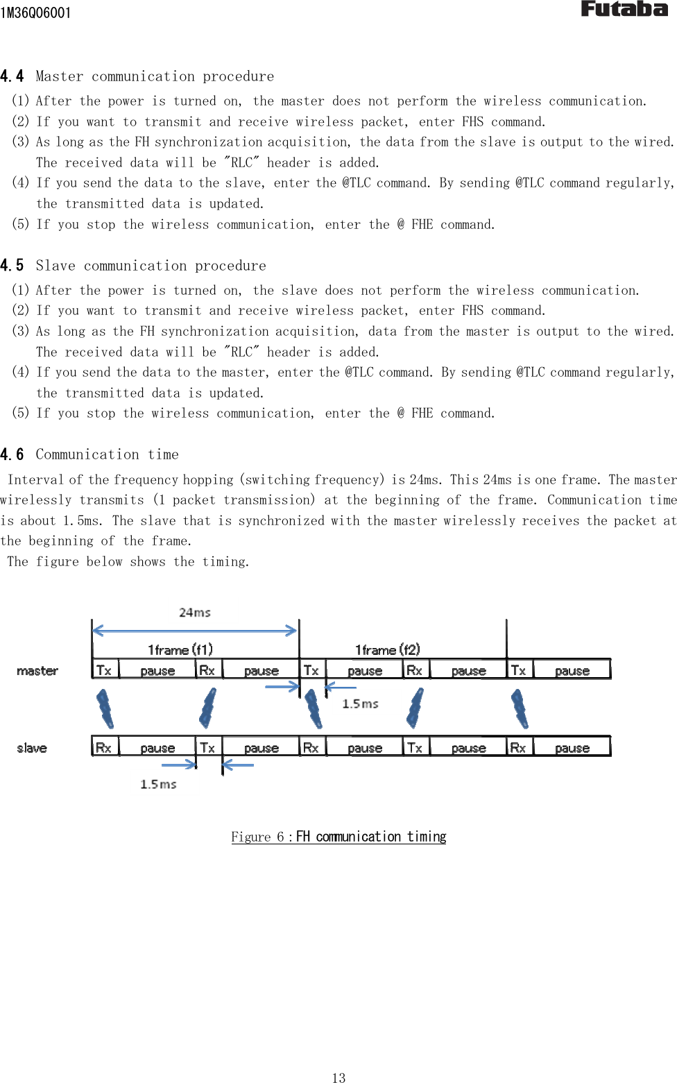
![1M36Q06001 12 4 Communication procedure 4.1 Overview Communication is done in the following manner: (1) Right after the power is turned on, the master and slave does not have wireless communication and is in an invalid state. (2) For sending/receiving a wireless packet, start the FH operation by inputting the @FHS command (the master and the slave). The master initiates RF transmission and reception. The slave starts RF reception, wait for communication from the master. (3) If FH synchronization acquisition, slave start also sent. After that, the slave will continue in automatic synchronization. (4) By TLC command to set the data you want to send. (5) In FH synchronization acquisition, it will receive the data periodically from the communication partner. If the synchronization is out, it does not receive the data. (6) To stop sending/receiving a wireless packet, type the @FHE command and quit the FH operation. 4.2 Send command The command header is "@TLC", the terminator is CR+LF (0x0D 0x0A). There is no response to the command. Please send data as a binary data of 14-byte fixed. Radio transmission will be run every 24ms. By @TLC command, it will update the transmitted data. If @TLC command is not inputted, the previous data is wirelessly transmitted. If you also send command has not been entered once, the data of all 0 is wireless transmitted. 【Send (update) format】 @TLC[Binary data 14 bytes][CRLF] 4.3 Received data The received data is appended "RLC" of 3 bytes as a header. The Received data is binary data of 14-byte fixed. Radio reception will be run every 24ms. In a state that can't be wireless communication, it will not be output to the wired. 【Reception format】Repeat RXT[Binary data 14 bytes]](https://usermanual.wiki/Futaba/FEX01T.User-Manual-Rev-02-160825/User-Guide-3112861-Page-12.png)
![1M36Q06001 15 5.1.1 6 Commands 6.1 List of commands Table 2:List of commands No. Command name Function 1 ARG Display all register values 2 DBM Reference a reception intensity of received packet 3 ERR Reference error status 4 FHE End FH operation 5 FHS Start FH operation 6 ID1 Reference and set pairing ID1 7 ID2 Reference and set pairing ID2 8 IDS Start ID registration 9 INI Initialize register values 10 ODA Disable output 11 OEN Enable output 12 REG Reference and set register values 13 RST Reset 14 TLC Set wireless data 15 VER Display version 6.2 How to use commands (1) When inputting a command to the wireless module, add 1 byte header for command recognition (command header) at the beginning of the command, in order to differentiate from regular data. The command header is “@” (40H). (2) Command is case-sensitive. (3) A 2-byte terminator is used to terminate a command. The terminator is [CRLF] (0DH: carriage return + 0AH: line feed). (4) The wireless module executes a command process after recognizing a command. For a command with a response, it returns the response to external devices after the process is completed. (5) Do not input subsequent commands or data before getting a response. (6) Command example @ARG[CRLF] 6.3 Command responses 6.3.1 Types of command responses Command responses and their meanings are: P0: normal termination P1: running command N0: command error N6: memory register writing error](https://usermanual.wiki/Futaba/FEX01T.User-Manual-Rev-02-160825/User-Guide-3112861-Page-15.png)
![1M36Q06001 16 6.4 Details of the command functions The symbols used in this section have the following meaning: [ ] : Required input parameter/s ( ) : Optional input parameter/s ARG :Display all register values 【Format】 ARG 【Response】 Setting list display N0 : command error 【Function】 ・ Refers to all contents of memory register. Displays a two-digit hexadecimal number plus H at the end. DBM : Reference the reception intensity of received packet 【Format】 DBM 【Response】 -XXXdBm : reception intensity N0 : command error 【Function】 ・Reads the reception intensity of the most recent, correctly received packet, and displays it in decibels. ・When none has been received after resetting, “-134dBm” is displayed. ・The signal strength indication is not absolute. It can be used for accurate relative measurements but should not be considered an absolute value. ERR :Reference error status 【Format】 ERR 【Response】 xxH :error status N0 :command error 【Function】 ・This command display the error information of the internal this module. If 00H is no error. ・bit2=1: memory (settings area) error ・bit1=1: memory (user area) error ・bit0=1: RF error](https://usermanual.wiki/Futaba/FEX01T.User-Manual-Rev-02-160825/User-Guide-3112861-Page-16.png)
![1M36Q06001 18 ID2 :Reference and set pairing ID2 【Format】 ID2(:pairing ID code 2) pairing ID code 2 : xxxxxxxxx(9-digit) 【Response】 xxxxxxxxx : pairing ID code 2 (when when referencing) P0 : normal termination (when setting) N0 : command error 【Function】 ・References and sets the pairing ID code 2. ・By inputting only the command, currently set values can be referenced. ・Specify the ID code (9-digit Serial Number) of the module that is the communication partner. ・Slave only is valid. ・The setting becomes effective after a reset. IDS :Start ID registration 【Format】 IDS:[pairing area] pairing area : x (1= pairing ID code 1, 2= pairing ID code 2) 【Response】 P0 : normal termination Pair : pairing is completed N0 : command error, or pairing is not completed N6 : memory register writing error 【Function】 ・Starts pairing operation. ・In the case of master, please specify '1' to the pairing area. ・In the case of slave, please specify '1' or '2' to the pairing area. INI : Initialize register value 【Format】 INI 【Response】 P0 : normal termination N0 : command error 【Function】 ・Resumes all contents of the memory register in the wireless module to the status at factory shipment.](https://usermanual.wiki/Futaba/FEX01T.User-Manual-Rev-02-160825/User-Guide-3112861-Page-18.png)
 Register number : 00~XX Set value : input a two-digit hexadecimal number with H at the end, or a three-digit decimal number without any suffix. 【Response】 XXX : currently set value (when referencing) P0 : normal termination (when setting) N0 : command error N6 : memory register writing error 【Function】 ・References and sets the memory register. ・By inputting only a register number, currently set values can be referenced. ・The setting will be valid after reset.](https://usermanual.wiki/Futaba/FEX01T.User-Manual-Rev-02-160825/User-Guide-3112861-Page-19.png)
![1M36Q06001 20 RST :Reset 【Format】 RST 【Response】 P0 : normal termination N0 : command error 【Function】 ・This module will be reset. TLC :Set wireless data 【Format】 TLC[binary data] Binary data : 14-bytes fixed 【Response】 None 【Function】 ・It specifies the data you want to send to the communication partner. It is 14-bytes fixed in binary data. ・In order to avoid the mixing of the received data, there is no response to this command. ・Input of this command, please as a 50ms interval at the shortest. VER : Display version 【Format】 VER 【Response】 Program Version 1.000 : display version N0 : command error 【Function】 ・Reads a program version of the wireless module. ・X.XXX Improvements and bug fixes within a range of specifications Minor specification change Major specification change](https://usermanual.wiki/Futaba/FEX01T.User-Manual-Rev-02-160825/User-Guide-3112861-Page-20.png)
![1M36Q06001 22 7.2 Memory register function detail REG00:Operation mode [default:00H] * Sets an operation mode (for the master or the slave). Table 4:Operation mode 00H Master (default) 01H Slave REG01:Reserved [default:00H] * Not used in this wireless module. Leave default setting. REG02:Frequency hopping pattern [default:00H] * Sets the frequency hopping pattern. It can be set to 00~1E (0~30). * Master only settings are valid. Slave sets the frequency hopping pattern automatically based on the information of the master. * In the initial state, a specific frequency hopping pattern is set. Because it is set to 00H if you initialize, please set again. * When using multiple systems within the same area, the frequency may periodically match and interfere with each other even when the frequency hopping patterns are different. REG03:Reserved [default:00H] * Not used in this wireless module. Leave default setting. REG04:Wireless communication setting 1 [default:08H] Bit7~4:Reserved * Not used in this machine. Make sure to set to 0. Bit3:Antenna diversity Table 5:Antenna diversity 0 Disable antenna diversity 1 Enable antenna diversity (default) * Enables/disables antenna diversity. * When used with two antennas, set to 1 in this bit. Bit2:Antenna selection Table 6:Antenna selection 0 Antenna is fixed to A (default) 1 Antenna is fixed to B * At the non-diversity reception, decide the antenna terminal.](https://usermanual.wiki/Futaba/FEX01T.User-Manual-Rev-02-160825/User-Guide-3112861-Page-22.png)
![1M36Q06001 23 Bit1~0:Reserved * Not used in this machine. Make sure to set to 0. REG05:Wireless communication setting 2 [default:00H] * Not used in this wireless module. Leave default setting. REG06:Reserved [default:00H] * Not used in this wireless module. Leave default setting. REG07:Reserved [default:00H] * Not used in this wireless module. Leave default setting. REG08:Wired communication setting 1 [default:01H] Bit 7: data length Table 7: Data length 0 8 bit data (default) 1 7 bit data Bit 6: parity bit Table 8: Parity bit 0 Without parity (default) 1 With parity Bit 5: Even/odd parity Table 9: Parity 0 Even parity (default) 1 Odd parity * Invalid when “without parity” is set in bit 6. Bit4: Stop bit Table 10: Stop bit 0 1 stop bit (default) 1 2 stop bit Bit3:Reserved * Not used in this machine. Make sure to set to 0.](https://usermanual.wiki/Futaba/FEX01T.User-Manual-Rev-02-160825/User-Guide-3112861-Page-23.png)
![1M36Q06001 24 Bit2~0:Baud rate setting Table 11:Baud rate Bit2 Bit1 Bit0 Baud rate 0 0 0 9600bps 0 0 1 19200bps(default) 0 1 0 Reserved 0 1 1 Reserved 1 0 0 Reserved 1 0 1 Reserved 1 1 0 Reserved 1 1 1 Reserved REG09:Wired communication setting 2 [default:00H] Bit7~5:Reserved * Not used in this machine. Make sure to set to 0. Bit4:Addition and deletion of CRLF Table 12:Addition and deletion of CRLF 0 Do not add the CR+LF code to the receive data. (default) 1 Add the CR+LF code to the receive data. * Sets whether adding the CRLF code or not to the received data. Bit3~0:Reserved * Not used in this machine. Make sure to set to 0. REG10~13:Reserved [default:00H] * Not used in this wireless module. Leave default setting. REG14~18:Pairing ID code 1 [default:00H] * Sets an ID code for a pairing machine. * Both the master and slave use this. REG19:Reserved [default:00H] * Not used in this wireless module. Leave default setting. REG20~24:Pairing ID code 2 [default:00H] * Sets an ID code for a pairing machine. * Only the slave use this.](https://usermanual.wiki/Futaba/FEX01T.User-Manual-Rev-02-160825/User-Guide-3112861-Page-24.png)
![1M36Q06001 25 REG25:Reserved [default:00H] * Not used in this wireless module. Leave default setting.](https://usermanual.wiki/Futaba/FEX01T.User-Manual-Rev-02-160825/User-Guide-3112861-Page-25.png)