Futaba FHSSBI-24G Radio Control User Manual
Futaba Corporation Radio Control
UserManual.wiki
>
Futaba
>
FHSSBI-24G User Manual
>
User Manual 1
Contents
1.
User Manual 1
2.
User Manual 2
User Manual 1
Navigation menu
Upload a User Manual
Namespaces
Wiki Guide
HTML
PDF
Info
Views
User Manual
Discussion / Help
Navigation
![31RSDUWRIWKLVPDQXDOPD\EHUHSURGXFHGLQDQ\IRUPZLWKRXWSULRUSHUPLVVLRQ7KHFRQWHQWVRIWKLVPDQXDODUHVXEMHFWWRFKDQJHZLWKRXWSULRUQRWLFH7KLVPDQXDOKDVEHHQFDUHIXOO\ZULWWHQ3OHDVHZULWHWR)XWDEDLI\RXIHHOWKDWDQ\FRUUHFWLRQVRUFODUL¿FD-tions should be made.)XWDEDLVQRWUHVSRQVLEOHIRUWKHXVHRIWKLVSURGXFWBattery Recycling (for U.S.A.)The RBRC™ SEAL on the (easily removable) nickel-cadmium battery and nickel-metal-hydride battery contained in Futaba products indicates that Futaba Corporation of America is voluntarily participating in an industry program to collect and recycle these batteries at the end of their useful lives, when taken out of service within the United States. The RBRC™ program provides a convenient alternative to placing used nickel-cadmium batteries and nickel-metal-hydride batteries into the trash or municipal waste system, which is illegal in some areas.You may contact your local recycling center for information on where to return the spent battery. Please call 1-800-8-BATTERY for information on NiCd/NiMH battery recycling in your area. Futaba Corporation of America's involvement in this program is part of its commitment to protecting our environment and conserving natural resources.NOTE: Our instruction manuals encourage our customers to return spent batteries to a local recycling center in order to keep a healthy environment.RBRC™ is a trademark of the Rechargeable Battery Recycling Corporation.2. Exportation precautions:(a) When this product is exported from the country of manufacture, its use is to be ap-proved by the laws governing the country of destination for devices that emit radio fre-TXHQFLHV,IWKLVSURGXFWLVWKHQUHH[SRUWHGWRRWKHUFRXQWULHVLWPD\EHVXEMHFWWRUH-strictions on such export. Prior approval of the appropriate government authorities may be required. If you have purchased this product from an exporter outside your country, and not the authorized Futaba distributor in your country, please contact the seller im-mediately to determine if such export regulations have been met.(b) Use of this product with other than models may be restricted by Export and Trade Control Regulations, and an application for export approval must be submitted.0RGL¿FDWLRQDGMXVWPHQWDQGUHSODFHPHQWRISDUWV)XWDEDLVQRWUHVSRQVLEOHIRUXQ-DXWKRUL]HGPRGL¿FDWLRQDGMXVWPHQWDQGUHSODFHPHQWRISDUWVRQWKLVSURGXFW$Q\VXFKchanges may void the warranty.4PLS-Eng-01-P2-3.indd 3 2013/04/06 11:28:08](https://usermanual.wiki/Futaba/FHSSBI-24G.User-Manual-1/User-Guide-1951863-Page-3.png)
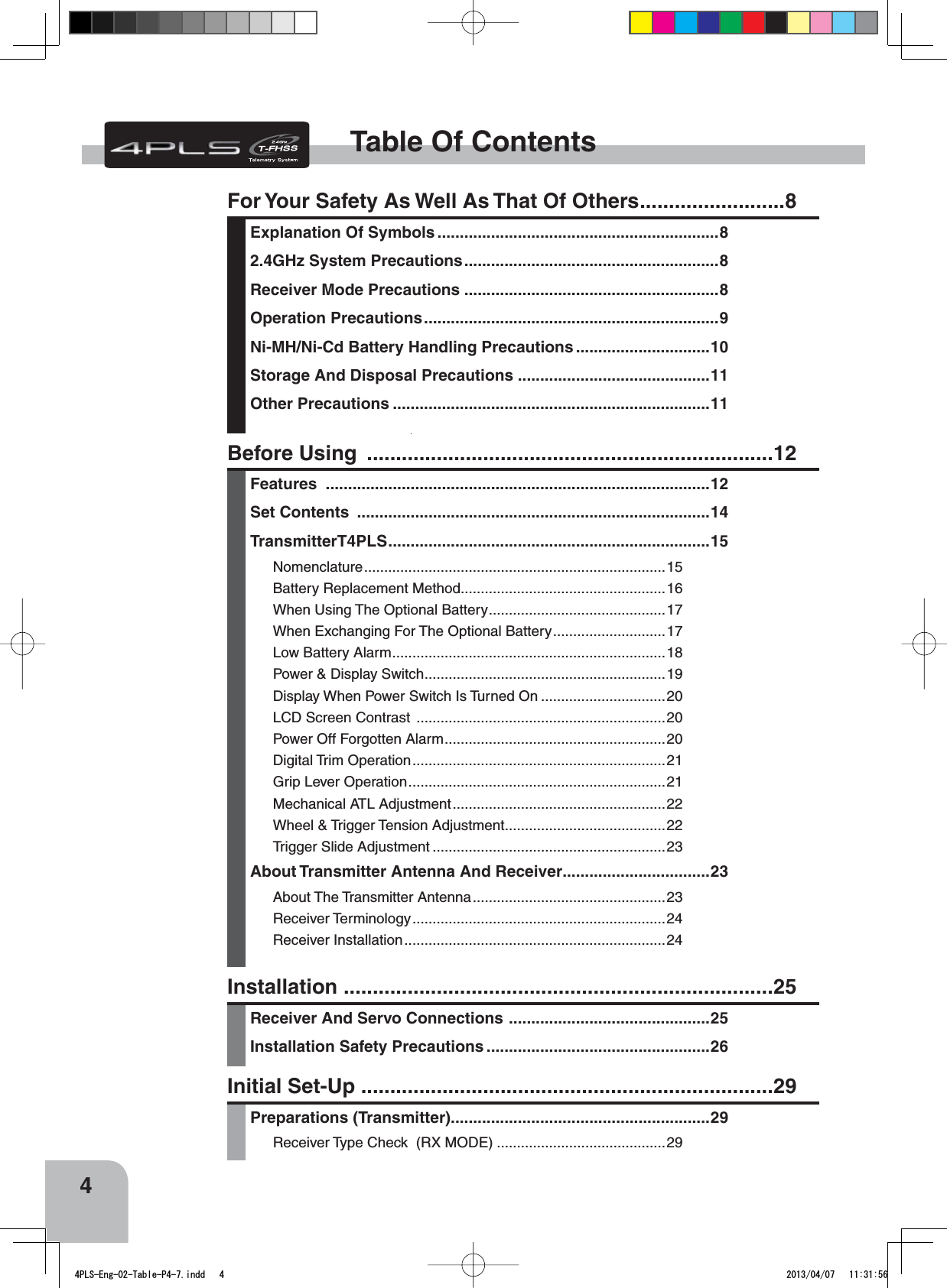


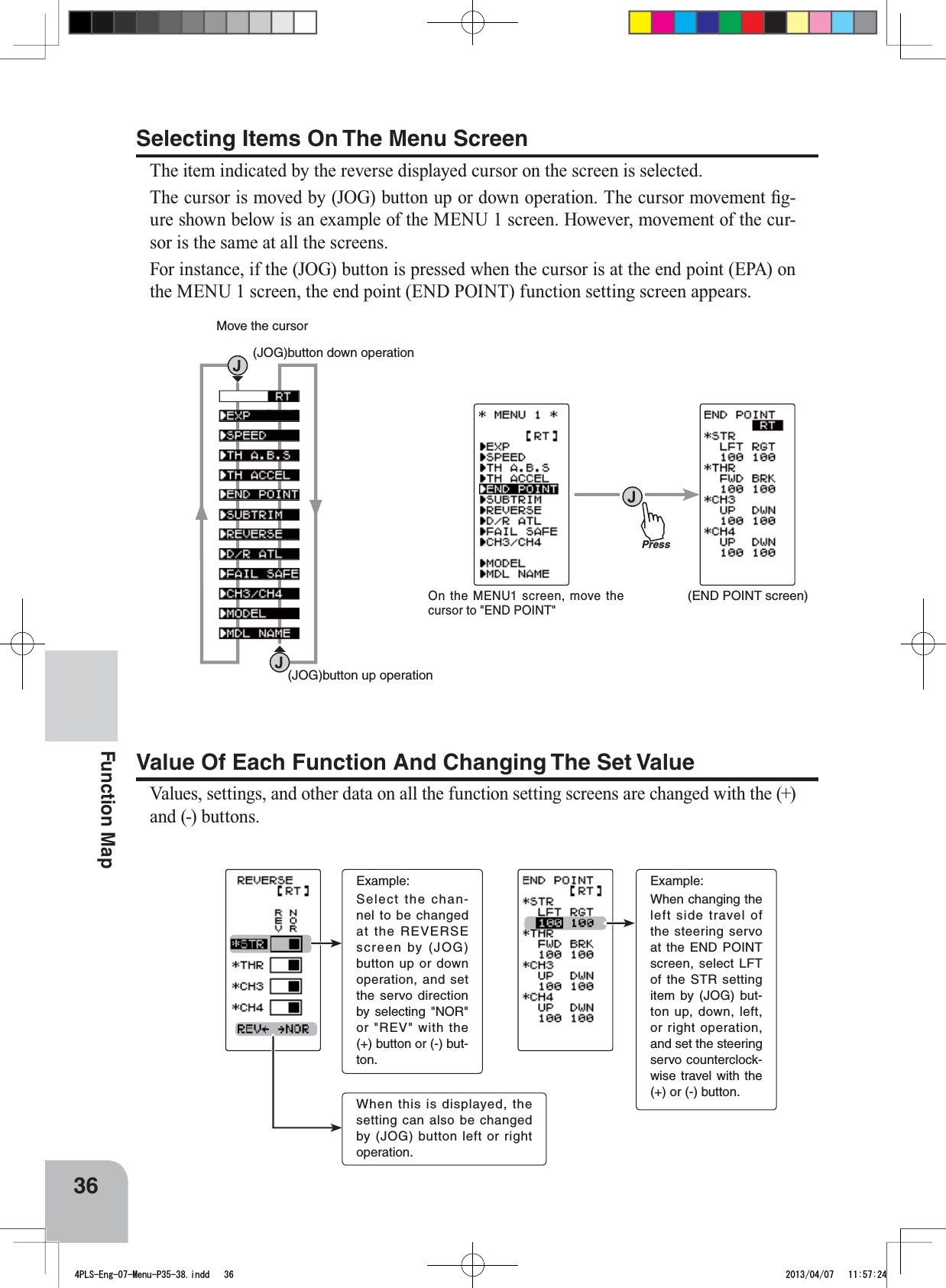
![(+) button is pressPress(-) button is pressPress(JOG) button is press(+) button(-) button(JOG) buttonPress(JOG)button up(JOG)button down(JOG)button left(JOG)button right(JOG)button up, down, left or right PressPressPressPressPress(DISP MENU screen)(MENU 2 screen)(MENU 1 screen)(HOME screen)On the MENU1 or 2 screen, move the cursor to [RT] by (JOG)button up or down operation and press the button.On the DISP MENU screen, move the cur-sor to "FUNC MENU" by (JOG) button up or down operation and press the button.35Function MapFunction MapOperation Of ScreenIn this instruction manual, Edit Buttons are represented by the symbols shown below.The (JOG) button can be operated in the 4 directions up, down, left, and right.Calling The Menu ScreenRefer to the below map for the method of displaying the function setting menu screen from the PWR ON initial screen or DISP (display) screen and the method of returning from the menu screen to the PWR ON initial screen or DISP (display) screen.4PLS-Eng-07-Menu-P35-38.indd 35 2013/04/07 11:57:24](https://usermanual.wiki/Futaba/FHSSBI-24G.User-Manual-1/User-Guide-1951863-Page-35.png)
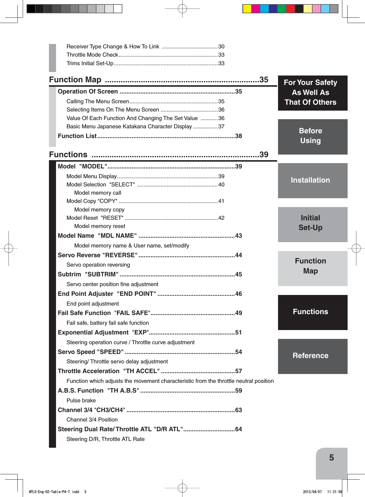
!["KATAKANA" charactersAlphabetic charactersEXPSPEEDTH A.B.STH A.B.STH ACCELEND POINTTRIMREVERSE D/R ATLD/R ATLFAIL SFECH3 /CH4CH3 /CH4MODELMDL NAME MIXBRAKE MIXPROG MIXPROG MIX4WS4WSESCDUAL ESCMIXGYRO MIXCPSMIXCPSMIXTHTH MODESW/SW/DIALTIMERLAP LISTSYSTEMADJUSTER (MENU 2 screen)(MENU 1 screen)(SYSTEM screen)(HOME screen)Call the MENU2 screen from the HOME screen by the (JOG) but-ton up, down, left or right opera-tion and press the (+) button.On the MENU2 screen, move the cursor to "SYSTEM" by the (JOG) button up or down op-eration and press the button.(MENU 2 screen)37Function MapBasic Menu Japanese Katakana Character DisplayOn the system menu, the basic menu screen shown below can be displayed in Japanese katakana characters.On the SYSTEM screen, select MENU by pressing the (JOG) button and select "ENG" or "" by pressing the (+) or (-) button.Changing the character After changing the setting, return to the MENU2 screen by pressing the (JOG) button or return to the HOME screen by se-lecting [RT] and pressing the (JOG) button.4PLS-Eng-07-Menu-P35-38.indd 37 2013/04/07 11:57:25](https://usermanual.wiki/Futaba/FHSSBI-24G.User-Manual-1/User-Guide-1951863-Page-37.png)
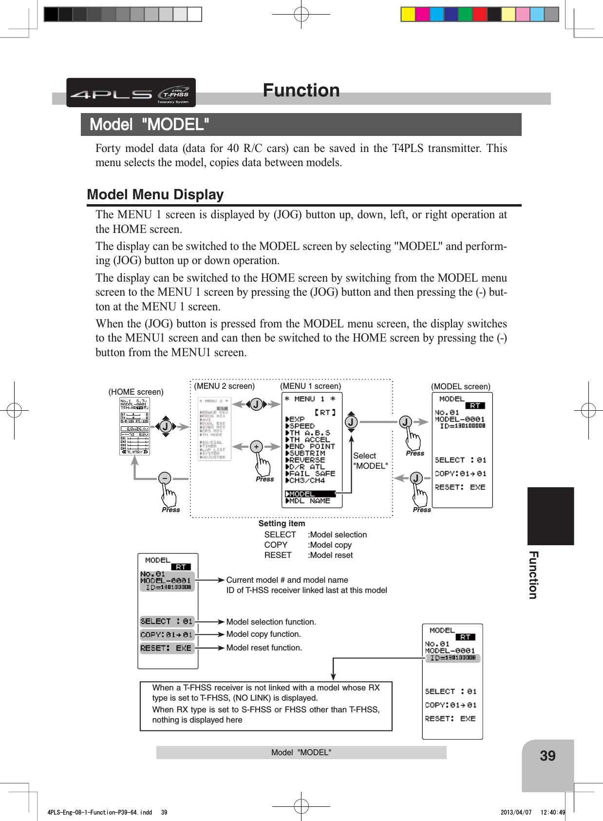
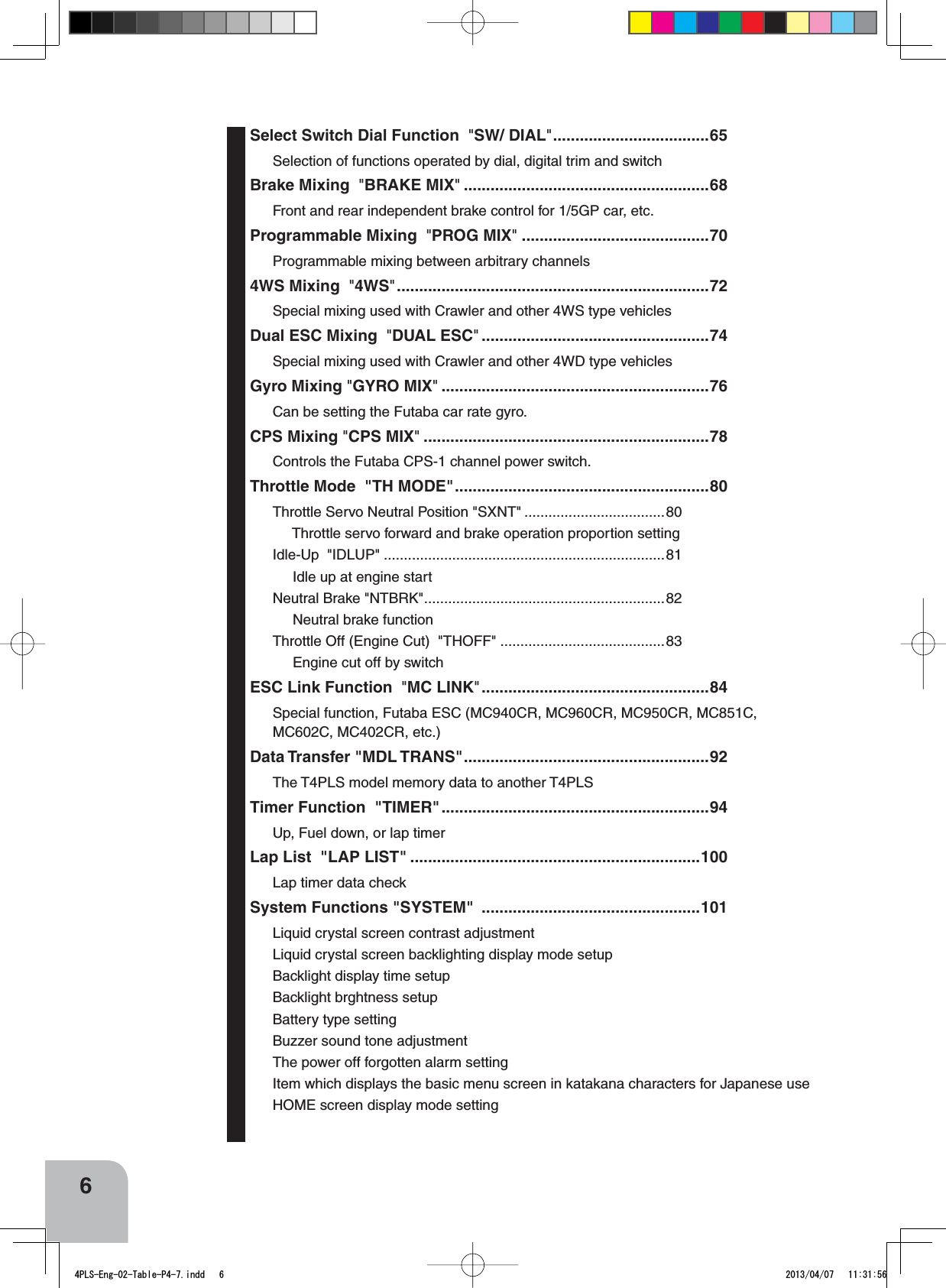
![Move the cursor to select mod-el # with the (JOG) button. Model #. 01~40Select model # with the (+) or (-) button.Modified model # and model name"COMPLELE!" is displayed.40FunctionModel Selection "SELECT"Forty model data (model data for 40 R/C cars) can be saved in the 4PLS transmitter and used when the relevant model data is called.Model "MODEL"When the model changed, use after turning the transmitter power off and on.- Display the MODEL screen by referring to P39.1(Selection of model select)Move the cursor to "SELECT" by the (JOG) button up or down operation.Using the model select function2(Model #. selection)Select the model number with the (+) or (-) button. "01" ~ "40" are displayed.3(Model select execution)Press the (JOG) buttons simultaneously for 1 second. A beeping sound is generated and the model is selected.- Model change is complete when the model No. and model name on the screen change and "COMPLETE!" is displayed .4When ending, move the cursor to [RT] by the (JOG) button, and return to the MENU1 screen by pressing the (JOG) button.4PLS-Eng-08-1-Function-P39-64.indd 40 2013/04/07 12:40:49](https://usermanual.wiki/Futaba/FHSSBI-24G.User-Manual-1/User-Guide-1951863-Page-40.png)
![Model name is also copied."COMPLELE!" is displayed.Move the cursor to "COPY" with the (JOG) button.The copy destination model # with the (+) or (-) button.Model #. 01~4041FunctionModel "MODEL"Model Copy "COPY"The contents of the currently selected model data can be copied to another model.- Display the MODEL screen by referring to P39.1(Selection of model copy)Move the cursor to "COPY" by the (JOG) button up or down operation.Using the model copy function2(Model #. selection)Select the copy destination model number with the (+) or (-) button. "01" ~ "40" are dis-played.3(Model copy execution)Press the (JOG) buttons for about 1 second. A beeping sound is generated and the model is selected.-Copying is complete when "COMPLETE!" is displayed on the screen.4When ending, move the cursor to [RT] by the (JOG) button, and return to the MENU1 screen by pressing the (JOG) button.4PLS-Eng-08-1-Function-P39-64.indd 41 2013/04/07 12:40:49](https://usermanual.wiki/Futaba/FHSSBI-24G.User-Manual-1/User-Guide-1951863-Page-41.png)
![Move the cursor to "RESET" with the (JOG) button."COMPLELE!" is displayed.The set RX type and T-FHSS receiver ID remain even if the model is reset. The same receiver can be used as is without re-linking42FunctionModel "MODEL"Using the model reset functionModel Reset "RESET"This function resets and initializes the contents of the currently selected model data.However, the adjuster function (ADJUSTER), system setting (SYSTEM), and type of receiver mode (TYPE) are not initialized.- Display the MODEL screen by referring to P39.1(Selection of model reset)Move the cursor to "RESET" by the (JOG) button up or down operation. 2(Model reset execution)Press the (JOG) buttons for about 1 second. A beeping sound is generated and the model is selected.-Resetting is complete when "COMPLETE!" is displayed on the screen.3When ending, move the cursor to [RT] by the (JOG) button, and return to the MENU1 screen by pressing the (JOG) button.4PLS-Eng-08-1-Function-P39-64.indd 42 2013/04/07 12:40:49](https://usermanual.wiki/Futaba/FHSSBI-24G.User-Manual-1/User-Guide-1951863-Page-42.png)
![Move the cursor to the char-acter you want to change by (+) or (-) button.Select the character by (JOG) button.Move the cursor to "RE-SET" by the (JOG) button up or down operation. Model nameUser nameCharacterPresscursor position [RT]PressPress(MDL NAME screen)PressSelect"MDL NAME"(HOME screen) (MENU 2 screen) (MENU 1 screen)When (JOG) button left or right operation is performed from both the left and right ends of the character list, the page (all 3 pages) is changed and the character set is selected.(KATAKANA of the 3rd page is displayed when "KANA" is set by the "SYSTEM" function "MENU".)43FunctionModel Name "MOE NAME"Setting the model name and user name1(Move the cursor to the character you want to change.)Select the model name character you want to set or change by moving the cursor by the (+) or (-) button. The selected character blinks.2(Selecting the character to be used)Select the character to be used from the character list at un-der side of the screen by the (JOG) button up, down, left, or right operation. The selected character blinks. After selecting the character to be used, press the (JOG) button. The char-acter is entered and the model name or user name character row moves to the right.Also move the cursor to "RESET" by the (JOG) button up, down, left, or right operation, and press the buttons for about 1 second. A beeping sound is generated and the model name is initialized to the factory setting.3When ending, move the cursor to [RT] by the (JOG) button, and return to the MENU1 screen by pressing the (JOG) but-ton.Model Name "MDL NAME"This function allows you to assign a ten character name to each model memory anduser name. Display to "MDL NAME" screen by the following method:4PLS-Eng-08-1-Function-P39-64.indd 43 2013/04/07 12:40:51](https://usermanual.wiki/Futaba/FHSSBI-24G.User-Manual-1/User-Guide-1951863-Page-43.png)
![Setting itemSTR :Steering (1st channel)THR :Throttle (2nd channel)CH3 :3rd channelCH4 :4th channelMove the cursor to "STR, THR, CH3 and CH4" with the (JOG) button.PressPress(HOME screen) (MENU 2 screen) (REVERSE screen)Press(MENU 1 screen)PressSelect"REVERSE"44FunctionServo Reverse "REV"However, when the position set by trim or subtrim shifts from the center, the center becomes the opposite side. Servo Reverse "REVERSE" (All channel)This function reverses the direction of operation of the servos related to transmitter steering, throttle, and channel 3 /4 operation.(Preparation)- Select the channel to be set by the (JOG) button up or down operation.1(Servo reverse setting)Use the (+) or (-) button to reverse the servo operation direction.NOR/REV can also be set by (JOG) button left or right operation(Each channel can be set similarly.)Servo Reverse Function SettingSelect button- Select with the (+) or (-) but-tons.Display to "REVERSE" screen by the following method:2When ending, move the cursor to [RT] by the (JOG) button, and return to the MENU1 screen by pressing the (JOG) but-ton.4PLS-Eng-08-1-Function-P39-64.indd 44 2013/04/07 12:40:52](https://usermanual.wiki/Futaba/FHSSBI-24G.User-Manual-1/User-Guide-1951863-Page-44.png)
![90°Use to adjust the neutral position Move the cursor to "STR, THR, CH3 and CH4" with the (JOG) button.Setting itemSTR :Steering (1st channel)THR :Throttle (2nd channel)CH3 :3rd channelCH4 :4th channelSubtrimPressPress(HOME screen) (MENU 2 screen) (SUBTRIM screen)Press(MENU 1 screen)PressSelect"SUBTRIM "Steering and throttle center trimWhen assigning DT1, DT2, or other digital trim-ming to another function, make adjustments at this screen.45FunctionSubtrim "SUBTR"Use this function to adjust the neutral position of the steering, throttle, channel 3 and channel 4 servos.(Preparation)- Set the steering and throttle digital trims to the neutral "0" posi-tion. Set CH3 and CH4 to the center "0" position. 1(Subtrim adjustment)Use the (+) or (-) button to adjust the center.(Each channel can be set similarly.)Subtrim adjustment*Subtrim adjusts the entire range of the servo in the set direction.Subtrim "SUBTRIM" (All channel)Adjust button- Adjust with the (+) and (-) but-tons.- Return to the initial value "0" by pressing the (+) and (-) buttons simultaneously for about 1 second.SubtrimST :L100~R100TH :B100~F100CH3 :-100~+100CH4 :-100~+100Initial value : 0Display to "REVERSE" screen by the following method:2When ending, move the cursor to [RT] by the (JOG) button, and return to the MENU1 screen by pressing the (JOG) but-ton.4PLS-Eng-08-1-Function-P39-64.indd 45 2013/04/07 12:40:53](https://usermanual.wiki/Futaba/FHSSBI-24G.User-Manual-1/User-Guide-1951863-Page-45.png)
![PressPressPressSelect"FAIL SAFE"Press(HOME screen) (MENU 2 screen) (FAIL SAFE screen)(MENU 1 screen)cursor position [RT]Setting itemMODE :F/S mode selectionPOSI :F/S positon setB-FS :B-FS set (throttle only)VOLT :B-FS voltage set (throttle only)49FunctionFail Safe Function "FAIL SAFE"Fail Safe Function "FAIL SAFE" (All channel)Fail Safe Mode (F/S)This function moves each servo to a preset position when the receiver cannot receive the signals from the transmitter for some reason.-When the condition set at "FHSS" is Rx type (P29), fail safe (F/S) can be set only for throttle (TH). Other channels are set to the normal mode.-The fail safe data is transferred from the transmitter to the receiver 10 seconds after the transmitter power was turned on. 7KHGDWDLVWUDQVIHUUHGHYHU\VHFRQGVDIWHUWKDW%HFDUHIXOEHFDXVHQRUPDOO\WKHWUDQVPLWWHUSRZHULVWXUQHGRQ¿UVWDQGWKHreceiver power is turned on next and the data is transferred for approximately 10 seconds after the receiver power is turned on.-For gasoline engine cars, for safety we recommend that this fail safe function be used to set the throttle channel in the direc-tion in which the brakes are applied.Hold mode (HOLD)This function holds the receiver in its position immediately before reception was lost. It is the T-FHSS typ (R304SB...etc) and the S-FHSS type (R2104GF...etc) receiver only function. When the receiver used is the R603GF/R2004GF and other FHSS type, this function cannot be used because the receiver type is set to "FHSS" by Rx type setting Off mode (OFF)This function stops output of signals to the servos and places the servos into the free state when the receiver cannot receive.The F/S, HOLD, and OFF modes are automatically reset when signals from the trans-mitter can be received again.Battery fail safe function (BFS)If the receiver battery voltage drops below a certain value when this function is enabled, the throttle servo moves to the position set by fail safe function. When the battery volt-age recovers, the battery fail safe function is automatically reset.-This function cannot be used when the throttle (TH) is not set to fail safe (F/S).-This function is for the T-FHSS typ (R304SB...etc) and the S-FHSS type (R2104GF...etc) receiver only. It cannot be used with the R603GF and R2004FG and other FHSS type.Display to "FAIL SAFE" screen by the following method:4PLS-Eng-08-1-Function-P39-64.indd 49 2013/04/07 12:40:56](https://usermanual.wiki/Futaba/FHSSBI-24G.User-Manual-1/User-Guide-1951863-Page-49.png)
![FAIL SAFE screenBattery fail safe functionOFF, ACTInitial value: OFFB-F/S Voltage3.8, 4.0, 4.2, 4.4, 4.6, 4.8, 5.0, 5.3, 5.6, 5.9, 6.2, 6.5, 6.8, 7.1, 7.4(V)Initial value 3.8vExample:Ni-MH /Ni-Cd 4cell---3.8VNi-MH /Ni-Cd 6cell---4.4VLiFe 2cell---4.8VLi-Po 2cell---5.6V50FunctionFail Safe Function "FAIL SAFE"(Preparation)- Select the channels "MODE" to be set by the (JOG) button up, down, left, or right operation. 1(Mode selection)Select the mode by (+) or (-) button.(Each channel can be individually set.)2When ending, move the cursor to [RT] by the (JOG) button, and return to the MENU1 screen by press-ing the (JOG) button. When setting fail safe, set the servo position by the following method.Fail safe mode selection(Preparation)- Select the setting item by the (JOG) button. For Battery F/S function ON/OF, select "OFF" or "ACT" of "B-FS". For voltage setting, select RX**v. (The T-FHSS system only. )The S-FHSS system is fixed at 3.8v.1(Battery fail safe function ACT/OFF)BATT-F/S function ACT/OFF and voltage set-ting which activates the B-F/S function can be switched by (+) or (-) button.Battery fail safe function ON/OFF (T-FHSS/ S-FHSS)1(Servo position setup)When the fail safe function operates, select the setting item "POSI" by the (JOG) button. The steering wheel, the throttle trigger or 3rd, 4th channel dial remains in the desired opera-tion position. When the (JOG) button is pressed for about 1 second, the servo position is displayed and you can confirm that the function was set.(Each channel can be set similarly.)2When ending, move the cursor to [RT] by the (JOG) button, and return to the MENU1 screen by pressing the (JOG) but-ton.Fail safe function setupF/S position setup button- The (JOG) buttons is pressed for about 1 second.F/S mode selection- Select with the (+) or (-) but-tons.F/S modeOFF, HOLD, F/S2When ending, move the cursor to [RT] by the (JOG) button, and return to the MENU1 screen by pressing the (JOG) but-ton.4PLS-Eng-08-1-Function-P39-64.indd 50 2013/04/07 12:40:57](https://usermanual.wiki/Futaba/FHSSBI-24G.User-Manual-1/User-Guide-1951863-Page-50.png)