User Manual
Applicable systems: Futaba T-FHSS Air-2.4GHz system transmitter
R3006SB T-FHSS Air-2.4GHz Bidirectional Communication System
S.BUS2 / S.BUS Port and 6 Channels for Conventional System Receiver
Compliance Information Statement
(for U.S.A.)
This device, trade name Futaba Corporation, model number R3006SB, complies with
part15 of the FCC Rules. Operation is subject to the following two conditions:
(1) This device may not cause harmful interference, and
(2) This device must accept any interference received, including interference that may
cause undesired operation.
CAUTION:
To assure continued FCC compliance:
1. Any changes or modications not expressly approved by the grantee of this device could
void the user's authority to operate the equipment.
2. This equipment complies with FCC radiation exposure limits set forth for an
uncontrolled environment.
To meet the RF exposure requirements of the FCC this device shall not be co-located with
another transmitting device.
The responsible party of this device compliance is:
Futaba Service Center
3002 N Apollo Drive Suite 1, Champaign, IL 61622 U.S.A.
TEL (217)396-6970 or E-mail: futabaservice@hobbico.com (Support)
R3006SB Specications
T-FHSS Air-2.4GHz system/S.BUS2 and S.BUS port and 6 channels for
conventional system receiver
• Dual antenna diversity
• Size: 1.7 x 0.98 x 0.35 in. (43.1 x 25.0 x 8.8 mm)
• Weight: 0.3 oz. (8.5g)
• Power requirement: 4.6V to 7.4V
• Battery F/S Voltage: It sets up with a transmitter
* Be sure that the battery is the correct size for the amount and type of servos
being used. When using a BEC, be sure that it is capable of delivering constant
voltage and can accept enough current that will be used by the RX and servos.
Do not use a dry cell battery with this system.
Thank you for purchasing a Futaba R3006SB T-FHSS Air-2.4GHz compatible receiver. The R3006SB receiver features bi-directional communication
with a T-FHSS Air-2.4GHz Futaba transmitter using the S.BUS2 port. Using the S.BUS2 port an impressive array of telemetry sensors may be utilized.
It also includes both standard PWM output ports and S.BUS output ports.
LED Indication
Green Red Status
Off Solid No signal reception
Solid Off Receiving signals
Alternate blink Unrecoverable error (EEPROM, etc.)
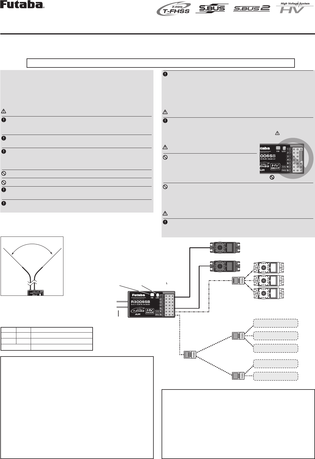
(Antenna installation)
90˚
Please refer the table below
for LED status vs receiver's
condition.
1M23N174xx
S.BUS2
port
S.BUS port
(SB/6)
(SB2/B)
S.BUS Servo
S.BUS Gyro
Mode switch
Antenna
LED
Servo for conventional
system
Channel1 output
Channel6 output
Battery to SB2/B
R3006SB Telemetry Sensor
S.BUS HUB
S.BUS HUB
S.BUS HUB
S.BUS HUB
Telemetry Sensor
Telemetry Sensor
Telemetry Sensor
Telemetry Sensor
*It's necessary to change it to
Mode B (S.BUS)
Usage precaution
• Futaba T-FHSS Air system does not work with current Futaba T-
FHSS / S-FHSS / FHSS / FASST / FASSTest system.
• The R3006SB receiver can only be used with T-FHSS Air capable
transmitters.
WARNING
Changes or modification not expressly approved by the party
responsible for compliance could void the user’s authority to operate the
equipment.
The R3006SB receiver should be protected from vibration by foam
rubber, Velcro or similar mounting methods. Protect from moisture.
Keep away from conductive materials to avoid short circuits.
Antenna installation precaution
Don't cut or bundle the receiver antenna wire.
Don't bend the coaxial cable. It causes damage.
The antennas must be mounted in such a way to assure they are
strain relieved.
Keep the antenna as far away from the motor, ESC and other noise
sources as you possibly can.
Be sure that the two antennas are placed at 90 degrees to each other.
• The R3006SB has two antennas. In order to maximize signal reception
and promote safe modeling Futaba has adopted a diversity antenna
system. This allows the receiver to obtain RF signals on both antennas
and fly problem-free.
Antenna installation for carbon fuselage
WARNING
You must leave 30mm at the tip of the antenna fully exposed. The ex-
posed antenna should be secured so that it cannot move around or back
inside of your aircraft.
S.BUS2 precaution
DANGER
Don't connect a connector, as shown right.
• It will be a short-circuit, if it connected in
this way. A short circuit across the battery
terminals may cause abnormal heat, fire
and burning.
Don't connect servo for conventional system to S.BUS/S.BUS2 port.
• Digital servo for conventional system→ It does not operate.
• Analog servo → It may cause abnormal heat, fire and burning.
WARNING
Only S.BUS2 capable devices may be connected the S.BUS2 port.
Standard S.BUS servos and gyros should not be connected the S.BUS2
port.
(Typical installation)
Receiver
DANGER
Do not insert either a switch
or battery in this manner.
本產品符合低功率電波輻射性電機管理辦法 第十二條、第十四條等條文
規定
1. 經型式認證合格之低功率射頻電機,非經許可,公司、商號或使用者均
不得擅自變更頻率、加大功率或變更原設計之特性及功能。
2. 低功率射頻電機之使用不得影響飛航安全及干擾合法通信 ;經發現有干
擾現象時,應立即停用,並改善至無干擾時方得繼續使用。前項合法通
信,指依電信法規定作業之無線電通信。低功率射頻電機須忍受合法通
信或工業 ,科學及醫療用電波輻射性電機設備之干擾。
WARNING
Do not perform the linking procedure while the motor's main wire con-
nected or the engine is operating as it may result in serious injury.
When the linking is complete, please cycle the receiver power and en-
sure the receiver is properly linked to the transmitter.
Please power up your system in this order. Transmitter first, followed
by the receiver.
FUTABA CORPORATION
1060 Yabutsuka, Chosei-mura, Chosei-gun, Chiba-ken, 299-4395, Japan
Phone: +61 475 32 6962, Facsimile: +61 475 32 6963
Link to the transmitter
Easy Link ID allows T-FHSS Air receivers to link to compatible
transmitter without pressing the link button on the receiver.
1 Bring the transmitter and the receiver close to each other,
within 20 inches (half meter).
2 Turn on the transmitter. Place the transmitter into the receiver
linking mode.
3 Turn on the receiver.
4 The receiver will wait for the linking process to begin for 3
seconds. Following that it will return to the normal operation
mode.
5 When the LED of the receiver changes from blinking red to
solid green, linking is completed.
(A link waiting state is ended in 3 second.)
• Refer to the transmitters operation manual for complete details on how to place the
transmitter into the linking mode.
• If there are many T-FHSS Air systems turned on in close proximity, your receiver
might have difficulty establishing a link to your transmitter. This is a rare occurrence.
However, should another T-FHSS Air transmitter/receiver be linking at the same
time, your receiver could link to the wrong transmitter. This is very dangerous if you
do not notice this situation. In order to avoid the problem,we strongly recommend
you to double check whether your receiver is really under control by your
transmitter.
• If the System Type of the transmitter is changed, the receiver will need to be re-
linked to the transmitter.
Channel Modes (S.BUS ⇔6CH )
The R3006SB is capable of changing its channel allocations as described
in the table below.
1 Turn on the receiver. (At this moment, the transmitter should
be off.) Then, LED blinks RED in about 3 seconds. Next, wait
until it becomes solid RED.
2 Press and hold the Mode switch more than 5 seconds.
3 Release the button when the LED blinks RED and GREEN
simultaneously.
4 The receiver is now in the "Operation CH Set" mode. At this
moment, the LED indicates current set status through flashing
a pattern that corresponds to the CH mode.
*Cannot exit this CH setting mode before the operation mode is xed.
**See the below table that shows correspondence between "CH mode" and way
of ashing LED.
***Default CH mode is "Mode 6CH".
5 By pressing the Mode switch, the operation CH is switched
sequentially as " Mode A" "Mode B" "Mode A"....
6 The operation mode will be set by pressing the Mode switch
more than 2 seconds at the desired CH mode.
7 Release the button when the LED blinks RED and GREEN
simultaneously. Then, the operation CH is fixed.
6 After confirming the operation CH mode is changed, turn off
and back on the receiver power.
*The “Operation CH Set” mode cannot be changed during the receiver
communicates to the transmitter.
T-FHSS Air
T-FHSS Air is a bidirectional communication system between the
R3006SB receiver and T-FHSS Air capable transmitters. Multiple
optional telemetry sensors may be connected to the S.BUS2 on the
receiver and that data is in turn displayed on the transmitter.
*Please see your transmitters operation manual to configure transmitter to
operate with telemetry sensors.
S.BUS2
S.BUS2 extends S.BUS and supports bidirectional communication.
Sensors are connected the S.BUS2 port.
*Only S.BUS2 capable devices may be connected the S.BUS2 port.
Standard S.BUS servos and gyros should not be connected the S.BUS2
port.
If the R3006SB receiver was previously linked to another transmitter,
make sure that transmitter is not operating while linking the receiver to
the new transmitter.
Mode A Mode B
6/SB 6CH S.BUS
Red LED blink 1 time 2 time
R3006SB CH Mode table
WARNING
Turn on the power in transmitter →receiver order. In addition, always check the operation of all the servos before flight.
Do not insert or remove the servo connector while the receiver power is ON.
Since the S.BUS servo switches the operation mode automatically according to the type of signal (S.BUS signal/PWM signal) from the receiver, if the connector is inserted
or removed while the power is ON, an S.BUS connected servo will be erroneously recognized and may stop.
©FUTABA CORPORATION 2015, 04 (1)
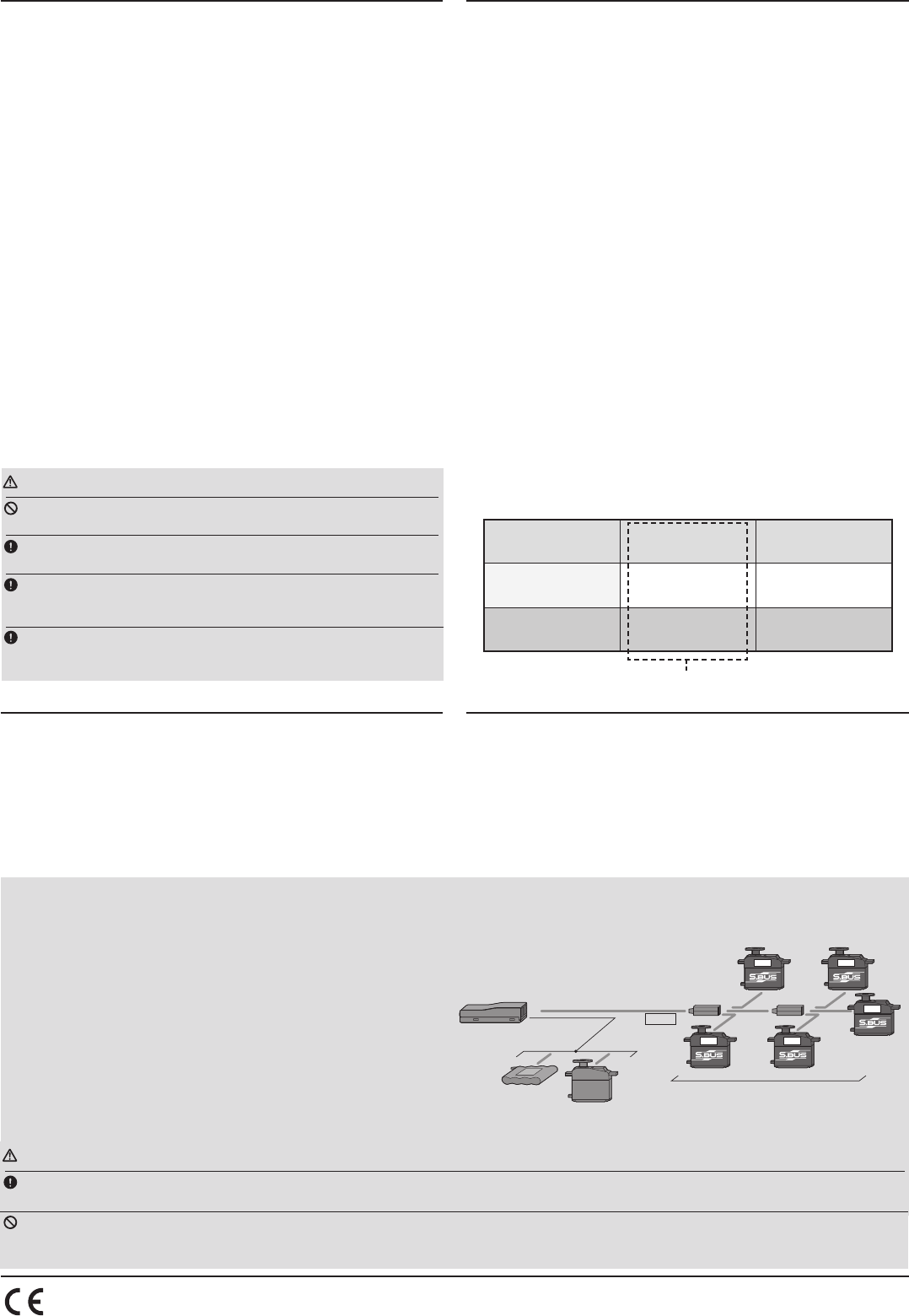
What is S.BUS?
Unlike conventional radio control systems, the S.BUS system uses data
communication to transmit control signals from a receiver to a servo,
gyro, or other S.BUS compatible device. This data includes commands
such as “move the channel 3 servo to 15 degrees, move the channel 5
servo to 30 degrees” to multiple devices. The S.BUS devices execute
only those commands for their own set channel. For this reason, it can
be used by connecting multiple servos to the same signal line. S.BUS hub S.BUS hub
S.BUS output
S.BUS
Ch output/
Battery terminal
R3008SB
Battery S.BUS servo
Conventional
servo
2ch 4ch
3ch 5ch
6ch
[Connection by S.BUS system]
* Set the channel of S.BUS servos by using an SBC-1 channel changer, CIU-2 USB
serial interface or the programming software resident in the T6K transmitter.
* Can also be used together with conventional servos. However, conventional ser-
vos cannot be used by the S.BUS output.
* When using servos with a remote battery pack, use S.BUS Hub with Cable (2-
way/remote battery pack use).
Please refer to the instruction manual of S.BUS Hub with Cable (2-way/remote
battery pack use) for the connection method.
Default CH mode