Futaba R7008SB-24G Radio Control User Manual manual revised
Futaba Corporation Radio Control manual revised
Futaba >
manual-revised
Applicable systems: Futaba FASSTest-2.4GHz system transmitter
R7008SB FASSTest-2.4GHz Bidirectional Communication System
S.BUS2 / S.BUS Port and 8 Channels for Conventional System Receiver
Compliance Information Statement
(for U.S.A.)
This device, trade name Futaba Corporation of America, model number
R7008SB, complies with part15 of the FCC Rules. Operation is subject to the
following two conditions:
(1) This device may not cause harmful interference, and
(2) This device must accept any interference received, including interference
that may cause undesired operation.
(3) This module meets the requirements for a mobile device that may be used
at separation distances of more than 20cm from human body.
To meet the RF exposure requirements of the FCC this device shall not be co-
located with another transmitting device.
The responsible party of this device compliance is:
Futaba Service Center
3002 N Apollo Drive Suite 1, Champaign, IL 61822 U.S.A.
TEL (217)398-8970 or E-mail: support@futaba-rc.com (Support)
R7008SB Specications
FASSTest-2.4GHz system(18CH/12CH mode)/S.BUS2 and S.BUS port
and 8 channels for conventional system receiver
• Dual antenna diversity
• Size: 0.98 x 1.86 x 0.56 in. (24.9 x 47.3 x 14.3 mm)
• Weight: 0.38 oz. (10.9g)
• Power requirement: 3.7V to 7.4V(Voltage range: 3.5 to 8.4V)
• Battery F/S Voltage: It sets up with a transmitter
• Extra Voltage port: 0 ~70V DC
* Be sure that when using ESCs regulated output the capacity of the ESC must
meet your usage condition.
Thank you for purchasing a Futaba R7008SB FASSTest-2.4GHz compatible receiver. The R7008SB receiver features bi-directional communication
with a FASSTest Futaba transmitter using the S.Bus2 port. Using the S.Bus2 port an impressive array of telemetry sensors may be utilized. It also
includes both standard PWM output ports and S.Bus output ports.
LED Indication
Green Red Status
Off Solid No signal reception
Solid Off Receiving signals
Alternate blink Unrecoverable error (EEPROM, etc.)
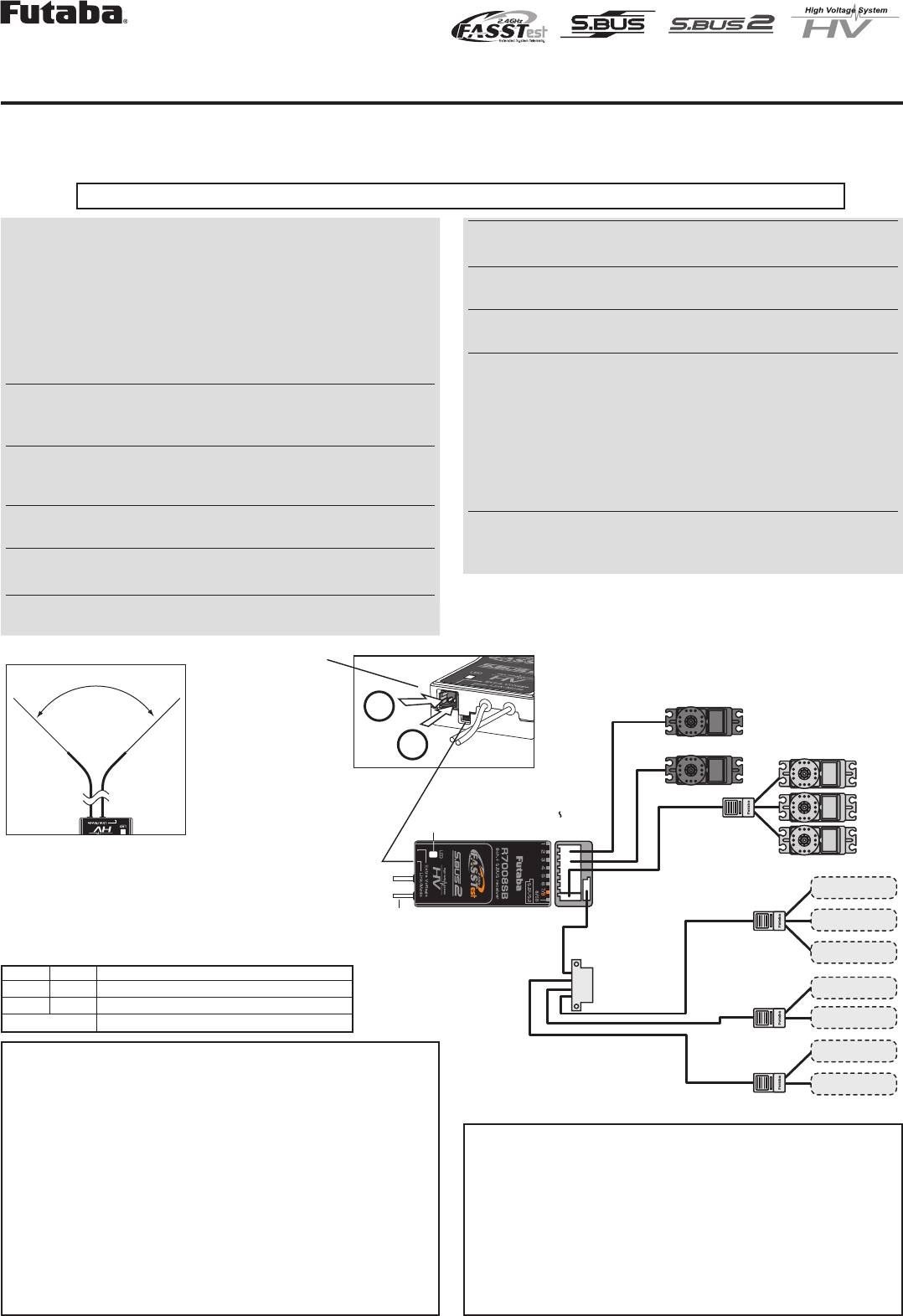
(Antenna installation)
90˚
Please refer the table below for LED status vs
receiver's condition.
1M23N17454
S.BUS2
port
S.BUS port (8/SB)
(S.BUS2)
R7008SB
Terminal box
S.BUS Servo
S.BUS Gyro
HUB
HUB
HUB
HUB
Extra Voltage
Port
Link/Mode switch
Antenna
LED
Servo for conventional
system
Channel1 output
Channel8 output
Temperature
Sensor
RPM
Sensor
Voltage
Sensor
Voltage
Sensor
Altitude
Sensor
Altitude
Sensor
S.BUS2 Tool
Battery to 7/B
(It is not used for a link.)
+
−
It connects with the
battery for power, etc.
External voltage input
cable of an option is
used. The voltage of
the battery can be
displayed with a
transmitter.
Usage precaution
•AnalogservoscannotbeusedwiththeR7008SBintheFASSTest
12CH mode.
•The R7008SB receiver can only be used with FASSTest capable
transmitters.
•Don'tconnectiontoExtraVoltagebeforeturningonareceiverpow-
ersupply.
WARNING
Changesormodicationnotexpresslyapprovedbythe
partyresponsibleforcompliancecouldvoidtheuser’s
authoritytooperatetheequipment.
TheR7008SBreceivershouldbeprotectedfromvibration
byfoamrubber,Velcroorsimilarmountingmethods.
Protectfrommoisture.
Keepawayfromconductivematerialstoavoidshort cir-
cuits.
Antenna installation precaution
Donotcutorbundlethereceiverantennawire.
Donotbendthecoaxialcable.Itcausesdamage.
Theantennasmustbemountedinsuchawaytoassure
theyarestrainrelieved.
Keeptheantennaasfarawayfromthemotor,ESCand
othernoisesourcesasyoupossiblycan.
Besurethatthetwoantennasareplacedat90degreesto
eachother.
•TheR7008SBhastwoantennas.Inordertomaximizesignalreception
and promote safe modeling Futaba has adopted a diversity antenna
system.ThisallowsthereceivertoobtainRFsignalsonbothantennas
andyproblem-free.
Antenna installation for carbon fuse
WARNING
Youmustleave30mmatthetipoftheantennafullyex-
posed.Theexposedantennashouldbesecuredsothatit
cannotmovearoundorbackinsideofyouraircraft.
(Typical installation)
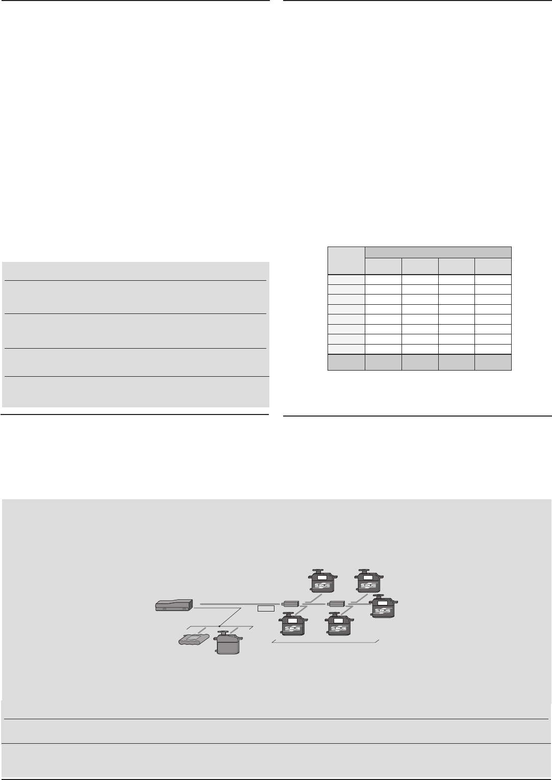
What is S.BUS?
Unlike conventional radio control systems, the S.BUS system
uses data communication to transmit control signals from a
receiver to a servo, gyro, or other S.BUS compatible device.
This data includes commands such as “move the channel 3
servo to 15 degrees, move the channel 5 servo to 30 degrees”
to multiple devices. The S.BUS devices execute only those
commands for their own set channel. For this reason, it can
be used by connecting multiple servos to the same signal
line.
[Connection by S.BUS system]
S.BUS hub S.BUS hub
S.BUS output
S.BUS
Ch output/
Battery terminal
R7008SB
Battery S.BUS servo
Conventional
servo
1ch 3ch
2ch 5ch
4ch
*SetthechannelofS.BUSservosbyusinganSBC-1channelchanger,CIU-2USBserialinterfaceortheprogrammingsoftwareresidentinthe18MZ transmitter.
* Can also be used together with conventional servos. However, conventional servos cannot be used by the S.BUS output.
* When using servos with a remote battery pack, use S.BUS Hub with Cable (2-way/remote battery pack use).
Please refer to the instruction manual of S.BUS Hub with Cable (2-way/remote battery pack use) for the connection method.
WARNING
Donotperformthelinking procedurewhilethemotor's
mainwireconnectedortheengineisoperatingasitmay
resultinseriousinjury.
Whenthelinkingiscomplete,pleasecyclethereceiver
powerandensurethereceiverisproperlylinkedtothe
transmitter.
Pleasepowerupyoursysteminthisorder.Transmitter
rst,followedbythereceiver.
FUTABA CORPORATION
1080 Yabutsuka, Chosei-mura, Chosei-gun, Chiba-ken, 299-4395, Japan
Phone: +81 475 32 6982, Facsimile: +81 475 32 6983
Link to the transmitter
Easy Link ID allows FASSTest receivers to link to compatible
transmitter without pressing the link button on the receiver.
1Bringthetransmitterandthereceiver closetoeachother,
within20inches(halfmeter).
2 Turnonthetransmitter.Placethetransmitterintothereceiver
linking mode.
3Turnonthereceiver.
4 The receiver will wait for the linking process to begin for 2
seconds. Following that it will return to the normal operation
mode.
5 When the LED of the receiver changes from blinking red to
solid green, linking is complete.
(Alinkwaitingstateisendedin1second.)
•Refertothetransmittersoperationmanualforcompletedetailsonhowtoplacethe
transmitterintothelinkingmode.
•If there are many FASSTest systems turned on in close proximity, your receiver
mighthavedifcultyestablishingalinktoyourtransmitter.Thisisarareoccurrence.
However,shouldanotherFASSTesttransmitter/receiverbelinkingatthesametime,
yourreceivercouldlinktothewrongtransmitter.Thisisverydangerousifyoudo
notnoticethissituation.Inordertoavoidtheproblem,westronglyrecommendyou
todoublecheckwhetheryourreceiverisreallyundercontrolbyyourtransmitter.
• If the SystemType of the transmitter is changed, the receiver will need to be re-
linkedtothetransmitter.
Channel Modes
The R7008SB is capable of changing its channel allocations as described
in the table below. This is especially important when using the receiver
in a dual receiver mode. See your transmitter operation manual for
complete details on operating in the dual receiver mode.
1PressandholddowntheLink/Modebuttonon the R7008SB
receiver.
2 TurnthereceiveronwhileholdingdowntheLink/Modebutton.
Afterpowerup,thebuttoncanbereleased.
3 The LED should now be blinking red in one of the patterns
describedbythechartbelow.
4 EachpressoftheMode/Linkbuttonadvancesthereceiverto
thenextmode.
5 Whenyoureachthemodethatyouwishtooperatein,press
andholdtheMode/Linkbuttonformorethan2seconds.
6 Once locked into the correct mode the LED will change to a
solid color.
7 Pleasecyclethereceiver(s)poweroffandbackonagainafter
changingtheChannelMode.
FASSTest
FASSTest is a bidirectional communication system between the R7008SB
receiver and FASSTest capable transmitters. Multiple optional telemetry
sensors may be connected to the S.BUS2 on the receiver and that data is
in turn displayed on the transmitter.
*Pleaseseeyourtransmittersoperationmanualtoconguretransmitterto
operatewithtelemetrysensors.
S.BUS2
S.BUS2 extends S.BUS and supports bidirectional communication.
Sensors are connected to the S.BUS2 port.
*OnlyS.Bus2capabledevicesmay beconnectedtotheS.Bus2port.
StandardS.BusservosandgyrosshouldnotbeconnectedtotheS.Bus2
port.
IftheR7008SBreceiverwaspreviouslylinkedtoanother
transmitter,makesurethattransmitterisnotoperating
whilelinkingthereceivertothenewtransmitter.
Output
connector
Channel
Mode A
1 ~ 8CH
Mode B
1 ~ 7CH
Mode C
9 ~ 16CH
Mode D
9 ~ 15CH
11199
2 2 2 10 10
3 3 3 11 11
4 4 4 12 12
5 5 5 13 13
6 6 6 14 14
7/B 7 7 15 15
8/SB 8 S.BUS 16 S.BUS
Red LED
blink 1 time 2 time 3 time 4 time
R7008SB CH Mode table
WARNING
Turnonthepowerintransmitter →receiverorder.Inaddition,alwayschecktheoperationofalltheservosbeforeight.
DonotinsertorremovetheservoconnectorwhilethereceiverpowerisON.
Since the S.BUS servo switches the operation mode automatically according to the type of signal (S.BUS signal/PWM signal) from the receiver, if the connector is
inserted or removed while the power is ON, an S.BUS connected servo will be erroneously recognized and may stop.
©FUTABA CORPORATION 2011, 11 (1)