User Manual
R7014SB
●Applicable systems: Futaba FASSTest-2.4GHz / FASST-Multi-ch system transmitter
◆FASSTest-2.4GHz Bidirectional Communication System / FASST-Multi-ch 2.4GHz
◆S.BUS2 / S.BUS Port and 12 Channels (+DG1,2) for Conventional System Receiver
1M23Nxxxxxx
Usage precaution
• Analog servos cannot be used with the R7014SB in the FASSTest
12CH mode.
• When the FASST Multi-ch High-speed Mode is used, analog servos
cannot be used at the CH1 〜6 outputs for convention systems. How-
ever, in other than the FASSTest 12CH mode, analog servos can be
used at CH7 〜12, DG1 and DG2 at any time.
• Don't connect to Extra Voltage Telemetry Port before turning on a re-
ceiver.
WARNING
Changes or modification not especially approved by the party
responsible for compliance could void the user’ s authority to operate the
equipment.
The R7014SB receiver should be protected from vibration by foam
rubber, Velcro, or similar mounting methods. Protect from moisture.
Antenna installation precaution
Do not cut or bundle the receiver antenna wire.
Do not bend the coaxial cable. It causes damage.
The antennas must be mounted in such a way to assure they are strain
relieved.
Keep the antenna as far away from the motor, ESC and other noise
sources as you possibly can.
Be sure that the two antennas are placed at 90 degrees to each other.
■The R7014SB has two antennas. In order to maximize signal reception and
promote safe modeling Futaba has adopted a diversity antenna system. This allows
the receiver to obtain RF signals on both antennas and fly problem-free.
Antenna installation for carbon fuselage
You must leave 30mm at the tip of the antenna fully exposed. The
exposed antenna should be secured so that it cannot move around or
back inside of your aircraft.
Be careful of connector insertion
Don't connect an S.BUS servo / gyro to S.BUS2 connector.
Do not connect the power supply battery to other than the power
supply connector.
■There is the danger of ignition, explosion, or burning.
Link precaution
Do not perform the linking procedure while the motor's main power
connected or the engine is operating as it may result in serious injury.
When the linking is complete, please cycle the receiver power and
ensure the receiver is properly linked to the transmitter.
Please power up your system in this order. Transmitter rst, followed
by the receiver.
If the R7014SB receiver was previously linked to another transmitter,
make sure that transmitter is not operating while linking the receiver to
the new transmitter.
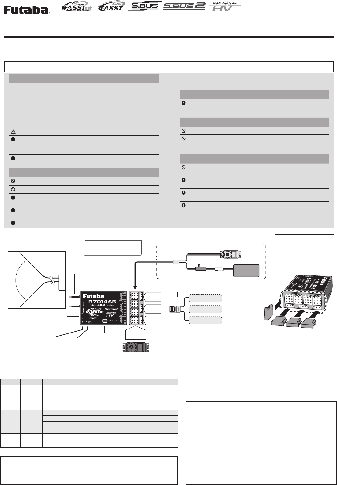
R7014SB
Link/Mode
switch
Antenna
Mode LED Link LED
Extra Voltage
Telemetry Port
Thank you for purchasing a Futaba R7014SB FASSTest-2.4GHz compatible receiver. The R7014SB receiver features bi-directional communication with a FASSTest
Futaba transmitter using the S.BUS2 port. Using the S.BUS2 port an impressive array of telemetry sensors may be utilized. It also includes both standard PWM output
ports and S.BUS output ports. The R7014SB can also be switched the FASST-Multi-ch System.
Compliance Information Statement (for U.S.A.)
This device, complies with part 15 of the FCC Rules. Operation is subject to the following three con-
ditions:
(1) This device may not cause harmful interference, and (2) This device must accept any interference
received, including interference that may cause undesired operation.
To assure continued FCC compliance:
1. Any changes or modifications not expressly approved by the grantee of this device could void the
user's authority to operate the equipment.
2. This equipment complies with FCC radiation exposure limits set forth for an uncontrolled
environment. This equipment should be installed and operated with minimum distance 20cm between
the radiator & your body.
The responsible party for the compliance of this device is:
Futaba Service Center
3002 N Apollo Drive Suite 1, Champaign, IL 61822 U.S.A
TEL (217)398-8970 or E-mail: support@futaba-rc.com (Support)
TEL (217)398-0007 or E-mail: futabaservice@hobbico.com (Service)
R7014SB Specications
FASSTest-2.4GHz system(14CH/12CH mode)
FASST-2.4GHz system (Multi-ch mode)
S.BUS2 and S.BUS port and Linear 12 ch +Digital 2 ch for conventional sys-
tem receiver
• Dual antenna diversity
• Size: 1.5 x 2 x 0.6 in. (37.0x50.2x15.9mm)
• Weight: 0.7 oz. (20.8g)
• Power requirement: 3.7V to 7.4V(Voltage range: 3.5 to 8.4V)
• Battery F/S Voltage: FASSTest:It sets up with a transmitter
FASST: 3.8V *The Battery F/S voltage is set for 4-cell NiCd/NiMH battery.
Battery F/S function doesn't work properly when other type battery is used.
• Extra Voltage port: 0 ~70V DC
本產品符合低功率電波輻射性電機管理辦法 第十二條、第十四條等條文規定
1. 經型式認證合格之低功率射頻電機,非經許可,公司、商號或使用者均不得擅自變更頻率、加大功率或
變更原設計之特性及功能。
2. 低功率射頻電機之使用不得影響飛航安全及干擾合法通信 ;經發現有干擾現象時,應立即停用,並改善
至無干擾時方得繼續使用。前項合法通信,指依電信法規定作業之無線電通信。低功率射頻電機須忍受
合法通信或工業、科學及醫療用電波輻射性電機設備之干擾。
CH1-12 Servos
Default : S.BUS port
It's possible to change to DG2.
S.BUS2
S.BUS
DG2
DG1
1~12
channel
Hub
S.BUS2equipment
Telemetry sensor
Telemetry sensor
The receiver power supply can
be connected to any port.
Battery
3.7 ~ 7.4V
Switch
Servo
Y-harness
When all ports are used.
90˚
Connection
(Antenna installation) Connector
The direction of the
connectors of the
bottom 3 ports is
different by 90˚.
LED Indication
System Mode LED Status Link LED
FASSTest Green
Solid
No signal reception Red Solid
Receiving signals Green Solid
Waiting for link Start → 2second later → Red
Blink(1second)
FASST O
No signal reception Red Solid
Receiving signals Green Solid
Receiving signals but ID is unmatched Green Blink
Waiting for link Red Blink
FASSTest
FASST -Unrecoverable error (EEPROM, etc.) Alternate blink
FUTABA CORPORATION
1080 Yabutsuka, Chosei-mura, Chosei-gun, Chiba-ken, 299-4395, Japan
Phone: +81 475 32 6982, Facsimile: +81 475 32 6983 ©FUTABA CORPORATION 2016, 11 (1)
All product and company names mentioned
herein are the trademarks or registered
trademarks of their respective owners.
*Fixed at neutral if a servo is connected to a port other than a usable transmitter channel.
*The telemetry and Extra Voltage ports cannot be used with the FASST system.
. Turn on the receiver.(Transmitter OFF)
. Press and hold the Link/Mode button for at least 5 seconds.
. When the mode LED begins to blink green/red the button may be released.
. The mode LED should now be blinking red in one of the patterns described by
the chart below. ( Default : FASSTest )
. Each press of the Mode/Link button advances the receiver to the next mode.
. When you reach the mode that you wish to operate in, press and hold the Mode/
Link button for more than 2 seconds.
. Once locked into the correct mode the mode LED will change to a solid color.
. Please cycle the receiver(s) power off and back on again after changing the
Channel Mode.
Mode LED Red blink System
FASSTest
FASST Multi-ch Normal mode
3 FASST Multi-ch High-speed mode
. Turn on the receiver.(Transmitter OFF)
. Press and hold the Link/Mode button for at least 15 seconds.
. When the mode LED begins to blink red the button may be released.
. The mode LED should now be blinking red in one of the patterns described by
the chart below. ( Default : S.BUS )
. Each press of the Mode/Link button advances the receiver to the next mode.
. When you reach the mode that you wish to operate in, press and hold the Mode/
Link button for more than 2 seconds.
. Once locked into the correct mode the mode LED will change to a solid color.
. Please cycle the receiver(s) power off and back on again after changing the
Channel Mode.
Mode LED Red blink System
S.BUS
DG2
FASSTest
FASSTest is a bidirectional communication system between the R7014SB receiver and FASSTest capable transmitters. Multiple optional telemetry sensors
may be connected to the S.BUS2 on the receiver and that data is in turn displayed on the transmitter.
*Please see your transmitters operation manual to configure transmitter to operate with telemetry sensors.
Bring the transmitter and the receiver close to each other, within 20 inches (half
meter).
Turn on the transmitter. Place the transmitter into the receiver linking mode.
Turn on the receiver.
The receiver will wait for the linking process to begin for 2 seconds. Following
that it will return to the normal operation mode.
When the link LED of the receiver changes from blinking red to solid green,
linking is complete. (A link waiting state is ended in 1 second.)
• Refer to the transmitters operation manual for complete details on how to place the
transmitter into the linking mode.
• If there are many FASSTest systems turned on in close proximity, your receiver might have
difficulty establishing a link to your transmitter. This is a rare occurrence. However, should
another FASSTest transmitter/receiver be linking at the same time, your receiver could link
to the wrong transmitter. This is very dangerous if you do not notice this situation. In order
to avoid the problem,we strongly recommend you to double check whether your receiver is
really under control by your transmitter.
• If the System Type of the transmitter is changed, the receiver will need to be re-linked to the
transmitter.
S.BUS2 extends S.BUS and supports bidirectional communication. Sensors
are connected to the S.BUS2 port.
*Only S.BUS2 capable devices may be connected to the S.BUS2 port. Standard S.BUS servos
and gyros should not be connected to the S.BUS2 port.
It connects with the battery for power, etc.
External voltage input cable (CA-RVIN-700) of an option is used. The
voltage of the battery can be displayed with a transmitter.
When using a TMA-1 (sold separately), change the settings by the following
method.
The TMA-1 is a device for viewing the telemetry data on a smartphone or
tablet.
. Switch the receiver to FASSTest system.
. Link the transmitter and receiver, and after confirming operation, turn off the
power.
. Turn on the receiver power. (Transmitter power off)
. Press the Link/Mode switch for at least 10 seconds.
. When the mode LED begins to blink green the button may be released.
. The receiver enters the linked with TMA-1 mode, and the LED begins red/
green simultaneous rapid blinking.
. Press the TMA-1 link switch until the LED starts to blink and wait for the
TMA-1 to link.
. When TMA-1 linking is complete, the TMA-1 LED changes from red to green
for a moment.
. When linking is complete, turn on the receiver power and check the
operation of all the devices.
Bring the transmitter and the receiver close to each other, within 20 inches (half
meter).
Turn on the transmitter and receiver.
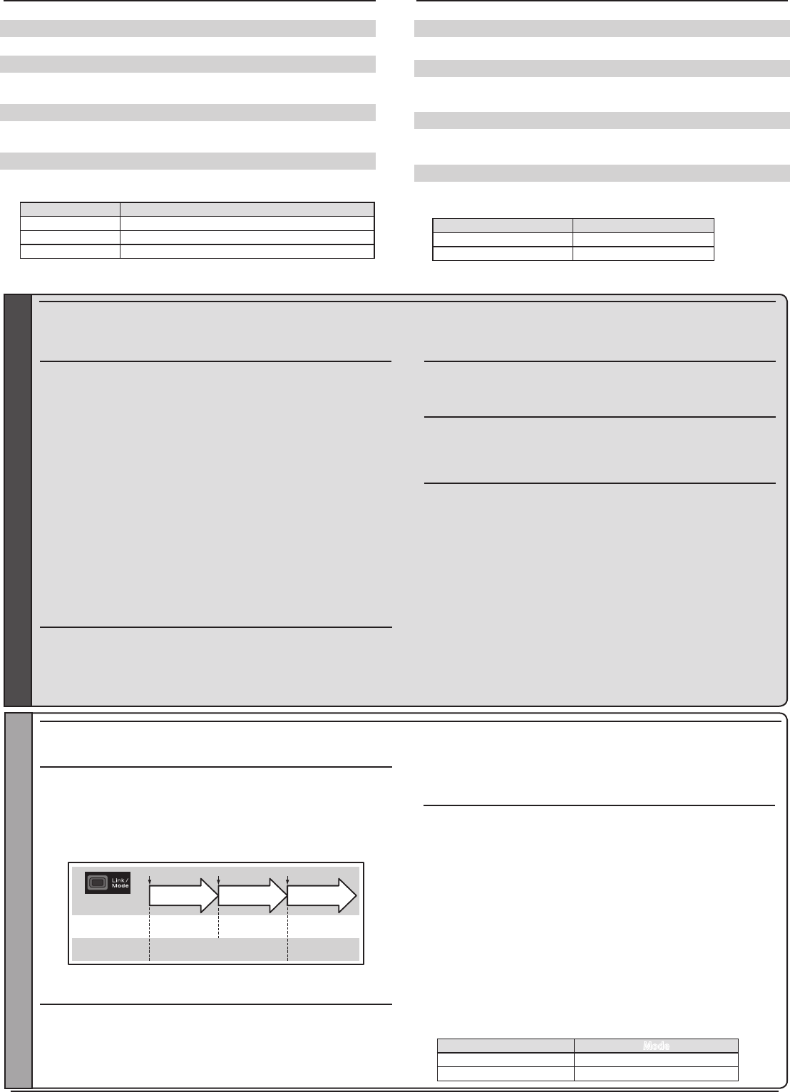
Link operation is performed by the Link/Mode switch.
• When using TM-8 module, it's possible to set F/S position (only 3CH).
0 to 1 sec. 1 to 2 sec. More than 2 sec.
0 sec. 1 sec. 2 sec.
Press and Hold time
No function
With TM-8
(not included in this set)
To set the F/S
position(No re-link)
Re-link(ID set) and to
set the F/S position
No function
Besides TM-8 Re-link(ID set)
*Refer to the instruction manual of the transmitter or module used for a description of the
linking operation, F/S position setting methods and other details.
The MPDX-1 can be used with FASSTest by merely setting the corresponding
transmitter. (Refer to the instruction manual of the corresponding transmitter.) When
using the MPDX-1 Multi Prop Decoder (sold separately) with the FASST system,
change the setting by the following method. Enable the MPDX-1 at channels 11 and
12. (Initial value: OFF) Channels 11 and 12 cannot be used individually for MPDX-
. Switch the receiver to the FASST system (Normal or High-speed).
. Turn on the receiver power. (Transmitter power off)
. Press the Link/Mode switch for at least 10 seconds.
. When the mode LED begins to blink green the button may be released.
. The receiver enters the multi prop mode and the LED of the current mode
blinks. (Initial value: OFF)
. Each time the switch is pressed, the mode changes.
. When the receiver was switched to the desired mode, press the Link/Mode
switch for at least 2 seconds.
. When the mode LED switches to red/green simultaneous rapid blinking,
mode switching is complete. Release the switch.
. When switching is complete, turn on the power. When the power is turned
on, the receiver switches to the new mode.
When switched, the R7014SB can use the FASST-Multi-ch mode. When the FASST system is used, the telemetry and Extra Voltage ports cannot be used. The
FASST system has a Normal mode and a High-speed mode. However, in the High-speed mode, analog servos cannot be used at CH1 〜6.
Mode LED Green blink Mode
1 time Multi prop mode OFF
2 time Multi prop mode ON
FASST
1 output.The MPDX-1 extends 1 channel to 8 channels. However, since the response
speed becomes slower and there are functional restrictions, use it at simple switch
operation and other applications that require numerous channels.
IC Warning:
This device complies with Industry Canada license-exempt RSS
standard(s). Operation is subject to the following two conditions:
(1) this device may not cause interference, and (2) this device
must accept any interference, including interference that may
cause undesired operation of the device.
This equipment complies with IC radiation exposure limits set
forth for an uncontrolled environment. This equipment should be
installed and operated with minimum distance 20cm between the
radiator and your body.
French: Cet appareil radio est conforme au CNR d’Industrie
Canada. L’utilisation de ce dispositif est autorisée seulement aux
deux conditions suivantes : (1) il ne doit pas produire de
brouillage, et (2) l’utilisateur du dispositif doit être prêt à accepter
tout brouillage radioélectrique reçu, même si ce brouillage est
susceptible de compromettre le fonctionnement du dispositif. Cet
équipement est conforme aux limites d’exposition aux
rayonnements IC établies pour un environnement non contrôlé.
Cet équipement doit être installé et utilisé avec un minimum de
20 cm de distance entre la source de rayonnement et votre corps.