Futaba RRC-R13 RRC-R13 2.4G User Manual AZPRRC R13 Use Manual
Futaba Corporation RRC-R13 2.4G AZPRRC R13 Use Manual
Futaba >
Use Manual REV1

V1.0 1/9 2009-4-7
AZPRRC-T13 & AZPRRC-R13
Spec V1.0
1. Summarize
AZPRRC-T13&AZPRRC-R13 is a 2.4G wireless robot controller. AZPRRC-T13 are
transmitters and AZPRRC-R13 are the receivers. However,AZPRRC-R13 also the
transmitters. The button and rocker action from AZPRRC-T13 will be send to the
AZPRRC-R13 by wireless means. When AZPRRC-R13 get the communication, it will
send the commands to RRC host controller to control the robot moves.
2. Electrical feature
Device end:
MCU working voltage:3.3V~6V
Current consume in natural status:10 ~ 20mA(battery working voltage 6V)
Current consume when sleeping:<30uA(battery working voltage 6V)
Dongle end:
MCU working voltage: 5V
Current consume in natural status:15 ~ 25mA
3. RF feature:
Working frequency:2403~2479MHz (bandwidth:1MHz)
Transmission power:0dBm(1mW)
Transmission velocity:1Mbps
Transmission distance:0~15m
RF statoscope:-85dBm(1Mbps)
Can skip frequency automatically, be of resisting interference power

V1.0 2/9 2009-4-7
4. Functional Description
A. Checking code manner:
Press the transmitter button to the code (CONNECT), the transmitter will enter to the
code mode, the LED on the transmitter will flicker on the rate of 16Hz, if fail to check
code or press the button again within 15s, the transmitter will exit to the code model.
Otherwise, the transmitter will enter into the working mode, and the LED on the
transmitter will stop flashing. Code mode of receiver is the same as transmitter.
B. Sleep mode
Transmitters at the following two circumstances will enter into Sleep mode.
a. In the case of disconnected circumstances, it will enter the sleep mode after 2
minutes.
b. In the case of connected circumstances without any operation, it will enter the sleep
mode after 5 minutes.
Wake-up transmitter operation are pressing any of a button from UP、RIGHT、DOWN、
LEFT、SELECT、START、1、2、3、4r on the transmitter.
C. Low-voltage mode
If transmitter voltage is lower than 3.8V, it will enter low-voltage mode 1. In this case,
LED on the transmitter will be flashing by the rate of 2Hz, if in connection mode, the
transmitter can be operated normally. If transmitter voltage is lower than 3.3V, it will
enter low-voltage mode2. LED on the transmitter will be extinguished, the transmitter
will stop working, it need to replace batteries before working.
D. LED instructions
LED on the tansmitter instructs the following functions:
a. line disconnection directions:blinking by 0.5Hz frequency.
b. code checking instructions: blinking by 16Hz frequency.
c. low-voltage mode 1 instructions: blinking by 0.5Hz frequency.
d. mode switching instructions in connection status: light express MODE button
information is 0; Crush out express MODE button information is 1.
LED on the receiver instructions:
LED2 instruct the power function.
LED1 instruct the following function:

V1.0 3/9 2009-4-7
a. line disconnection directions:blinking by 0.5Hz frequency.
b. code checking instructions: blinking by 16Hz frequency.
c. connection status, LED is light.
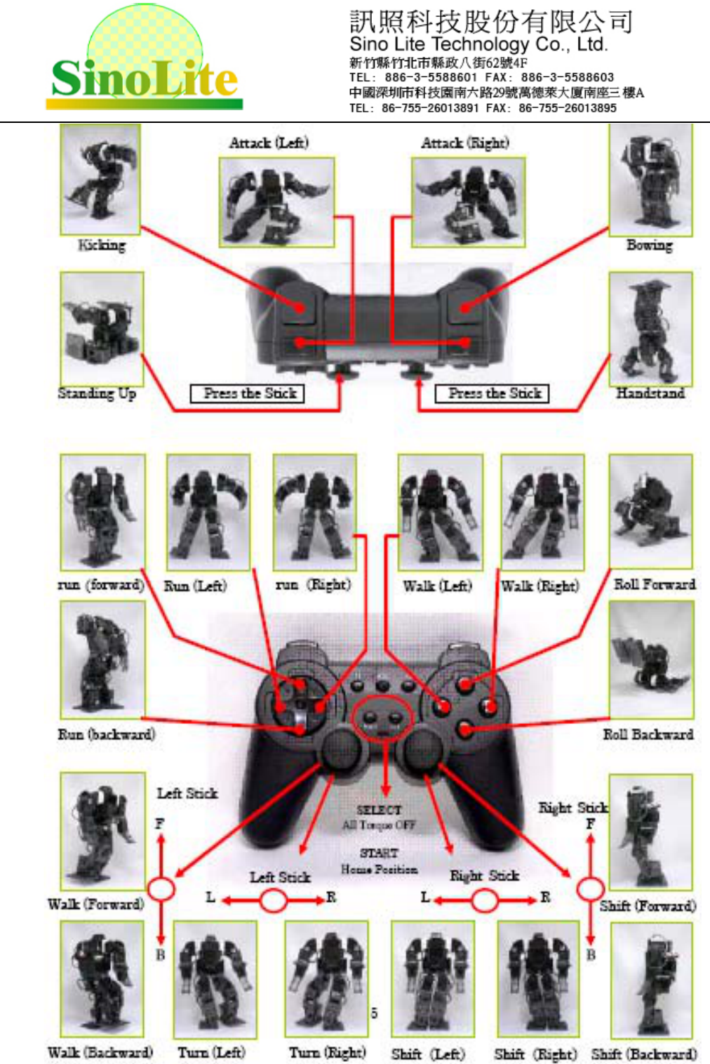
5. Working mode
Transmitter contain 16p digital function buttons, they are UP, RIGHT, DOWN, LEFT,
L1,L2, L3, R1, R2, R3, SELECT, START, 1,2,3,4 as well as two 3D Rockers, detail
operation is as follows.
There are another two special function buttons MODE and CONNECT. In connection
status, LED will always light instructions by pressing the MODE button on the
transmitter, communication information will contain the information MODE button will
be set to 0. Communication information will contain the information that MODE button
will be set to 1 when press the MODE button again, and the same time, the LED on
transmitter will be turned off. CONNECT function buttons has already stated at the
front.
V1.0 4/9 2009-4-7
V1.0 5/9 2009-4-7
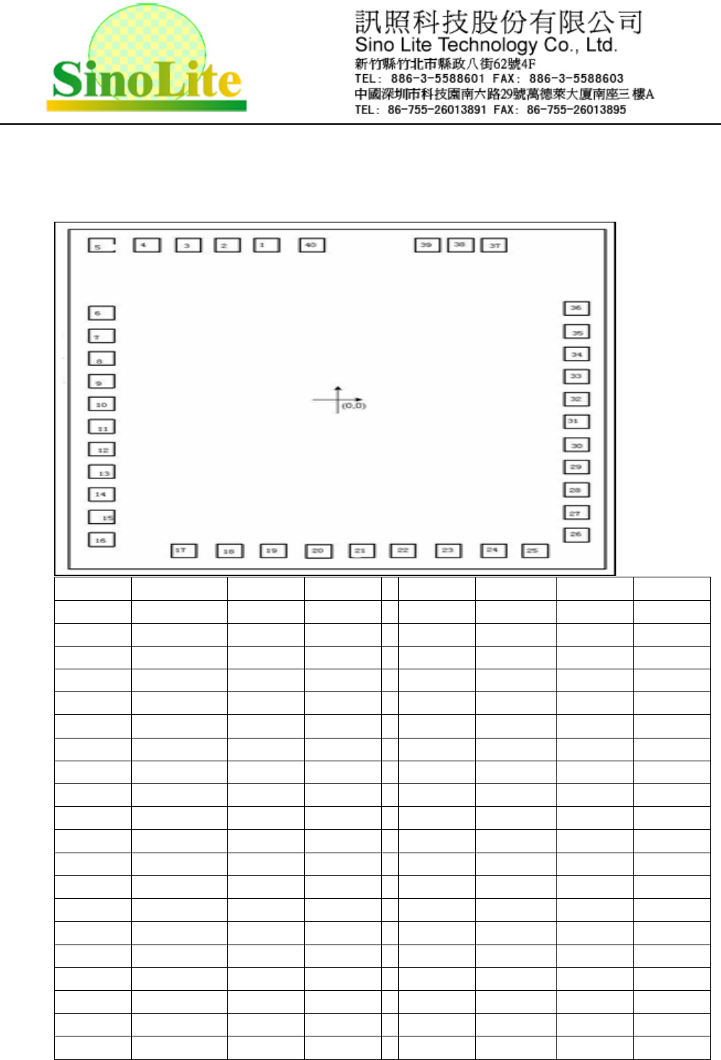
6. PAD diagram
A. AZPRRC-T13 DISE PAD diagram
Pad NO. Sym X Y Pad NO. Sym X Y
1 GND -257.8 1015 21 SPIEN -1.9 -1015
2 INT -362.8 1015 22 RSDAT 103.2 -1015
3 DATA -471.1 1015 23 TRSCLK 208.2 -1015
4 CLK -582.7 1015 24 TRRDY 313.2 -1015
5 AU -691 1015 25 TRINT 418.1 -1015
6 AL -715 89.5 26 PCB 715 -960.5
7 L1 -715 -15.5 27 BU 715 -855.5
8 L2 -715 -120.5 28 BR 715 -750.5
9 CONNECT -715 -225.5 29 BD 715 -645.5
10 MODE -715 -330.5 30 BL 715 -540.5
11 LY -715 -435.5 31 START 715 -435.5
12 LX -715 -540.5 32 SELECT 715 -330.5
13 RY -715 -645.5 33 AR 715 -225.5
14 RX -715 -750.5 34 AD 715 -120.5
15 R3 -715 -855.5 35 SCL 715 -15.5
16 ADN -715 -960.5 36 LVD2 715 89.5
17 R2 -421.8 -1015 37 Q1 407.6 1015
18 R1 -316.8 -1015 38 VDD 302.5 1015
19 LVD1 -211.8 -1015 39 OSCO 197.6 1015
20 L1 -106.8 -1015 40 OSC1 -152.8 1015
V1.0 6/9 2009-4-7
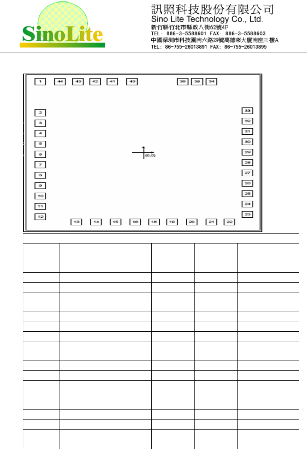
B. AZPRRC-R13 diagram
Red marks burning feet. pleas separated it from the external circuit when burning
Pad NO. Sym X Y Pad NO. Sym X Y
1 NC -691 1015 22 NC 418.1 -1015
2 NC -715 89.5 23 CS 715 -960.5
3 DO -715 -15.5 24 SDA 715 -855.5
4 DI -715 -120.5 25 SCL 715 -750.5
5 CLK -715 -225.5 26 NC 715 -645.5
6 P95 -715 -330.5 27 NC 715 -540.5
7 P50 -715 -435.5 28 NC 715 -435.5
8 LED1 -715 -540.5 29 NC 715 -330.5
9 NC -715 -645.5 30 NC 715 -225.5
10 NC -715 -750.5 31 CONNECT 715 -120.5
11 NC -715 -855.5 32 NC 715 -15.5
12 NC -715 -960.5 33 NC 715 89.5
13 NC -421.8 -1015 34 REST 407.6 1015
14 NC -316.8 -1015 38 VDD 302.5 1015
15 NC -211.8 -1015 39 OSCI 197.6 1015
16 R5 -106.8 -1015 40 OSCO -152.8 1015
18 R6 -1.9 -1015 41 GND -257.8 1015
19 R7 103.2 -1015 42 INT -362.8 1015
20 R8 208.2 -1015 43 DATA -471.1 1015
21 R9 313.2 -1015 44 CLK -582.7 1015
The above pin-pin in line with PACKAGE

V1.0 9/9 2009-4-7
Caution
1. Changes or modifications not expressly approved by the party responsible for
compliance could void the user's authority to operate the equipment.
2. This device complies with part 15 of the FCC Rules. Operation is subject to the
following two conditions: (1) This device may not cause harmful interference, and (2)
this device must accept any interference received, including interference that may
cause undesired operation.
3. NOTE: This equipment has been tested and found to comply with the limits for a
Class B digital device, pursuant to Part 15 of the FCC Rules. These limits are designed
to provide reasonable protection against harmful interference in a residential
installation. This equipment generates, uses and can radiate radio frequency energy
and, if not installed and used in accordance with the instructions, may cause harmful
interference to radio communications. However, there is no guarantee that interference
will not occur in a particular installation. If this equipment does cause harmful
interference to radio or television reception, which can be determined by turning the
equipment off and on, the user is encouraged to try to correct the interference by one or
more of the following measures:
-- Reorient or relocate the receiving antenna.
-- Increase the separation between the equipment and receiver.
-- Connect the equipment into an outlet on a circuit different
from that to which the receiver is connected.
-- Consult the dealer or an experienced radio/TV technician for help.
Note
For updates or more information, we will not make another notification, so , please
confirm the information is the latest version in your hands before using.
For the consequences because of wrong or inappropriate operation, we will not
assume responsibility.