Futaba T2PHKA-75 Radio Control (R/C) Ststion User Manual Manual
Futaba Corporation Radio Control (R/C) Ststion Manual
Futaba >
Manual

Thank you for purchasing a Futaba 2PH/2PHKA.
Before using your 2PH/2PHKA, read this manual carefully and
use your R/C set safely.
After reading this manual, store it in a safe place.
-No part of this manual may be reproduced in any form without prior permission.
-The contents of this manual are subject to change without prior notice.
-This manual has been carefully written. Please write to Futaba if you feel that any corrections or clarifications
should be made.
-Futaba is not responsible for the use of this product.
APPLICATION, EXPORT, AND RECONSTRUCTION
1. This product may be used for models only.
The product described in this manual is subject to regulations of the Ministry of Radio/Telecommu-
nications and is restricted under Japanese law to such purposes.
2. Exportation precautions
(a) When this product is exported from Japan, its use is to be approved by the Radio Law of the
country of destination.
(b) Use of this product with other than models may be restricted by Export and Trade Control Regu-
lations. An application for export approval must be submitted.
3. Modification, adjustment, and replacement of parts
Futaba is not responsible for unauthorized modification, adjustment, and replacement of parts of this
product.
THE FOLLOWING STATEMENT APPLIES TO THE RECEIVER (FOR U.S.A.)
This device complies with part 15 of the FCC Rules. Operation is subject to the following two
conditions:
(1) This device may not cause harmful interference, and
(2) This device must accept any interference received, including interference that may cause
undesired operation.
THE RBRCTM SEAL (FOR U.S.A.)
The RBRCTM SEAL on the (easily removable) nickel-cadmium battery contained in Futaba products
indicates that Futaba Corporation of America is voluntarily participating in an industry program to
collect and recycle these batteries at the end of their useful lives, when taken out of service within the
United States. The RBRCTM program provides a convenient alternative to placing used nickel-cad-
mium batteries into the trash or municipal waste which is illegal in some areas.
Futaba Corporation of America's payments to RBRCTM makes it easy for you to return the spent bat-
tery to Futaba for recycling purposes. You may also contact your local recycling center for informa-
tion on where to return the spent battery. Please call 1-800-8-BATTERY for information on Ni-Cd
battery recycling in your area. Futaba Corporation of America's involvement in this program is part of
its commitment to protecting our environment and conserving natural resources.
NOTE: Our instruction manuals need to encourage our customers to return spent
batteries to Futaba or a local recycling center in order to keep a healthy environment.
RBRCTM is a trademark of the Rechargeable Battery Recycling Corporation.
Warning: This product contains a chemical known to cause cancer and birth defects (or other
reproductive harm).

1
Before Operation........................................................................ 6
System Contents.............................................................................................................................6
Nomenclature / Handling.............................................................................................................7
Assembly / Adjustment .............................................................. 9
Receiver And Servo Connection.................................................................................................9
Assembly Precautions.................................................................................................................10
Digital Proportional Adjustment..............................................................................................12
Safety Precautions ...................................................................... 2
Definition Of Symbols....................................................................................................................2
Running Preparations Safety Precautions................................................................................2
Running Safety Precautions.........................................................................................................3
Storage And Disposal Safety Precautions................................................................................4
Other Safety Precautions.............................................................................................................5
Description Of Functions ......................................................... 13
Steering Trim................................................................................................................................13
Throttle Trim................................................................................................................................13
Servo Reverse................................................................................................................................13
Steering EPA..................................................................................................................................14
Throttle EPA.................................................................................................................................14
Steering D/R...................................................................................................................................14
MC230CR/MC330CR....................................................................................................................15
Reference ................................................................................... 16
Ratings.............................................................................................................................................16
Troubleshooting............................................................................................................................17
Table Of Contens

2
Safety Precautions
For your safety as well as that of others. Please read this manual thoroughly prior to instal-
lation and operation of your digital proportional R/C system.
Definition Of Symbols
The following defines the symbols used in this manual.
Explanation Of Symbols
Warning
Indicates a procedure that could result in serious injury or death to the user
or other persons if ignored and not performed properly.
Caution
Indicates a procedure that may result in serious injury to the user or other
persons, as well as physical damage. If ignored and not performed properly.
Safety Precautions
Explanation Of Graphic Symbols
Indicates an operation that prompts a warning (including Caution).
Indicates an operation that must not be performed.
Indicates an operation that always must be performed.
Caution
(When using a Ni-cad battery to power your system)
When the charger is not in use, disconnect from the outlet.
To prevent accidents, overheating and short circuits.
Running (Sailing) Preparations Safety Precautions
Warning
(When using a Ni-cad battery to power your system)
Charging
When using a Ni-cad battery to power your system, always charge and check the
battery voltage prior to operation.
Should the battery discharge below the minimum voltage level, control will be lost.

3
Safety Precautions
Running (Sailing) Safety Precautions
Warning
Conduct Tests
Prior to operation always preform a range test.
Even one abnormality in the R/C system may cause loss of control.
[Range Test Procedure]
Have a friend hold the model, or place on a stand where the wheels or prop can not
come in contact with any object. Collapse the transmitter antenna and operate from a
distance of about 10 yards. Be sure to check the movement of each servo to make
sure they follow the movement of the steering wheel and throttle trigger. If the servos
do not follow the commands from the transmitter or any type of interference is de-
tected, Do Not operate the model.
Fully extend the transmitter antenna.
If the transmitter antenna is not fully extended range will be reduced and control may
be lost.
Prohibited
Do not operate two or more models on the same frequency at the same time.
Operation of two or more models on the same frequency at the same time will cause
interference and loss of control of both models.
AM, FM and PCM are different methods of modulation. Nonetheless the same fre-
quency can not be used at the same point in time, regardless of the signal format.
Do not operate outdoors on rainy days
Never operate in the rain or run through puddles.
The transmitter, receiver, batteries and most servos, and speed controls are not wa-
terproof. Contact with any type of moisture or immersion in water or snow will cause
damage along with possible loss of control. Should any type of moisture enter any
component of the system immediately stop using the R/C system and return to our
service center for inspection.
Prohibited
Do not operate when visibility is limited.
Should you loss sight of the model a collision or other dangerous situation may occur.
Prohibited
Do not operate near people or roads.
Do not operate near high tension power lines or communication broadcasting anten-
nas.
Prior to the operation of any model be sure the area you plan to use is safe. Be aware
of all object that may be in the path of your model. Do not operate the model where
people or any type of moveable object could stray in the path of your model. Control
loss due to interference, component failure, loss of sight or low battery voltage could
result in serious injury to yourself and others as well as damage to your model.
Prohibited
Do not Operate your R/C system within 1 mile of another site where radio control
activity may occur.
Interference from other R/C systems will cause loss of control.
4
Safety Precautions
Prohibited
Do not operate when you are tired, not feeling well or under the influence of alcohol or
drugs.
Your judgement is impaired and could result in a dangerous situation that may cause
serious injury to yourself and others.
Before you turn on the power switch on the transmitter, always check to see that the
trigger is at the neutral position. Always turn the transmitter on first, then the receiver.
When you turn the system off, always turn the receiver off first then the transmitter.
This step is very important always follow this procedure.
If this procedure is not followed, injury to yourself and others as well as loss of control
could occur.
Adjustment Note
Make all adjustments to the radio control system with engine not running, or the elec-
tric motor disconnected.
If the engine is running or the motor is connected while adjustments are made the
model may run out of control.
Remove the main battery source from electric powered models when they are not
being used.
Should you accidently leave the receiver switch on the model could run out of control.
Caution
Do not touch
Do not touch the engine, motor, speed control or any part of the model that will gener-
ate heat while running.
Touching hot parts will result in serious burns.
Storage And Disposal Safety Precautions
Warning
(When using a Ni-cad battery to power your system)
At the end of a days operation store the system with Ni-cad battery discharged. Be
sure to recharge the system before it is used again.
You should fully discharge your systems batteries periodicity to prevent a condition
called "memory". For example if you only make two run in a day or you regularly use a
small amount of the batteries capacity, the memory effect can reduce the actual ca-
pacity even if the battery is charged for the recommended amount of time.
Prohibited
Do not throw a Ni-cad battery into a fire. Do not disassemble or attempt to repair a Ni-
cad battery pack.
Overheating, damage and acid leakage may lead to burns, loss of eye sight as well as
numerous other types of injuries. The electrolyte in Ni-cad batteries is a strong alkali.
Should you get even the smallest amount of the electrolyte in your eyes, Do Not rub,
wash immediately with water, seek medical attention at once. The electrolyte can
cause blindness. If electrolyte comes in contact with your skin or clothes, wash with
water immediately.
5
Safety Precautions
Other Safety Precautions
Caution
When operating two or more models at the same time, have a third person act as a
spotter. They will be in charge of safety and you should follow their instructions.
Beginners should receive instructions regarding safety and operation from an experi-
enced modeler.
Use genuine Futaba parts only.
Always use only genuine Futaba receiver, servos, electronic speed controls along with
other optional parts and components.
Futaba will not be held responsible for damages caused by other than genuine Futaba
parts and components. Use only genuine Futaba parts and components listed in the
instruction manual and catalog.
(When using a Ni-cad battery to power your system)
Prohibited
Do not short circuit the Ni-cad battery terminals.
Short circuiting the terminals will lead to sparks and overheating and could cause a fire
and burns as well.
Caution
Prohibited
Do not store your R/C system where it will be exposed to the following conditions.
• Extreme heat or coldness
• Exposed to direct sunlight
• Where humidity is high
• Where vibration is prevalent
• Where dust is prevalent
• Where there is steam and condensation
• Where the system would be exposed to engine exhaust
Storing your R/C system under adverse conditions could cause deformation and nu-
merous other problems with operation.
(When using a Ni-cad battery to power your system)
Caution
When disposing Ni-cad batteries, cover any exposed contacts with some type of insu-
lation to prevent short circuit.
Improper disposal could cause fire.
*Special Note!
Some states require special handling when Ni-cad batteries are disposed. Con-
tact the State Agency responsible for recycling hazardous waste for the proce-
dures in your state.
6
Before Operation
Before Operation
System Contents
After opening the container, check the contents for the following items. the contents will
vary with the system purchased.
System with
2 Servos System with
1 Servo
System with
E.S.C. and
Servo
Transmitter
Receiver
Servo
E.S.C.
Switch
Battery Holder
Miscellaneous
T2PH or T2PHKA (x1)
R122JE (x1)
S3003 (x2) S3003 (x1)
MC230CR (x1)
or MC330CR (x1)
CSW-BN (x1)
R2-BSS-N (x1)
Servo mounting hardware and servo horns
Mini Screwdriver
Should any item be missing or you are uncertain of the contents of the system, please
contact the dealer where the unit was purchased.
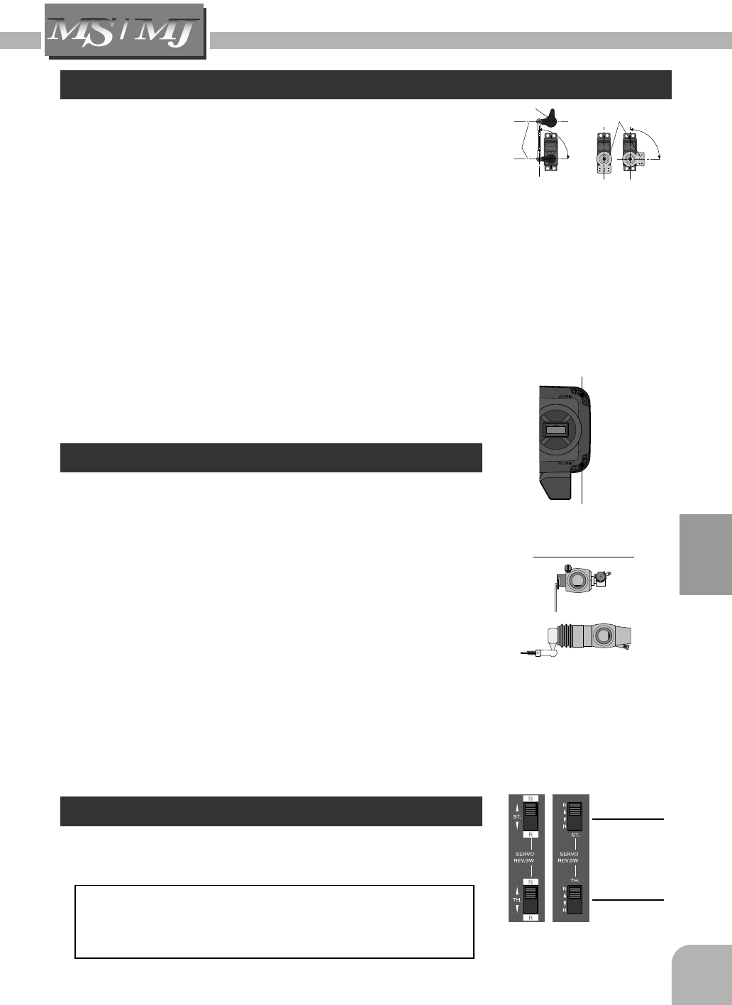
Receiver R122JE
Output Connector
"CH.1" : Steering Servo
"CH.2" : Throttle Servo
Power Supply Connector (BATT)
Servo S3003
Crystal
Servo Horn Mounting Flange
To Receiver
FP-R122JE
AM 2 CHANNEL RECEIVER
BEC
X'TAL CH.2
CH.1
BATT
7
Before Operation
Transmitter T2PH / T2PHKA
Nomenclature / Handling
(T2PH)
(T2PHKA)
Antenna
Trim Panel Cover
Battery Level
Indicator
*Two LED display to indicate
battery voltage level.
*If the Red led flashes, replace
batteries.
*Open the cover by sliding it
to the left.
Steering Trim (P13)
Steering Wheel
Throttle Trigger
Grip Handle
¥ Servo Reversing Switch (P13)
¥ Steering EPA (only 2PHKA) (P14)
¥ Throttle EPA (only 2PHKA) (P14)
¥ Steering D/R (only 2PHKA) (P14)
Power Switch
Throttle Trim (P13)
*When slid upward,
the power is turned on.
*Adjusts the steering in small increments
so the model will run straight.
*Turn model to left or right.
*Adjusts the throttle in small increments
so the model will not move at neutral.
*Control the speed of the model and movement
forward and backward.
E.S.C. MC230CR
/ MC330CR
Motor connector
Connects to the motor.
(Orange) is plus. (Blue) is minus.
If the motor rotates in the wrong
direction, interchange the connections of
this connector.
Nicd battery connector
Connects to the running Nicd battery.
(Red) is plus. (Black) is minus.
Receiver connector
Connects to the receiver throttle channel.
Miniature screwdriver
Accessory. Use to press the
pushbutton switch.
Checker LED
Power switch
Pushbutton
switch
MC230CR
(Orange)
(Blue)
(Black)
(Red)
Applicable motors
(Number of turns is criteria.)
•Use the MC230CR with a motor with 20T or more turns.
•Use the MC330CR with a motor with 13T or more turns.
*If a motor with a number of turns smaller than the above is used, the heat
protector and overcurrent protection circuit may operate. The number of turns
of the motor is a criteria only. Depending on the running conditions, the
protection circuit may operate even if the condition above is satisfied.
Nicd battery 6~7 cells (7.2~8.4V)
8
Before Operation
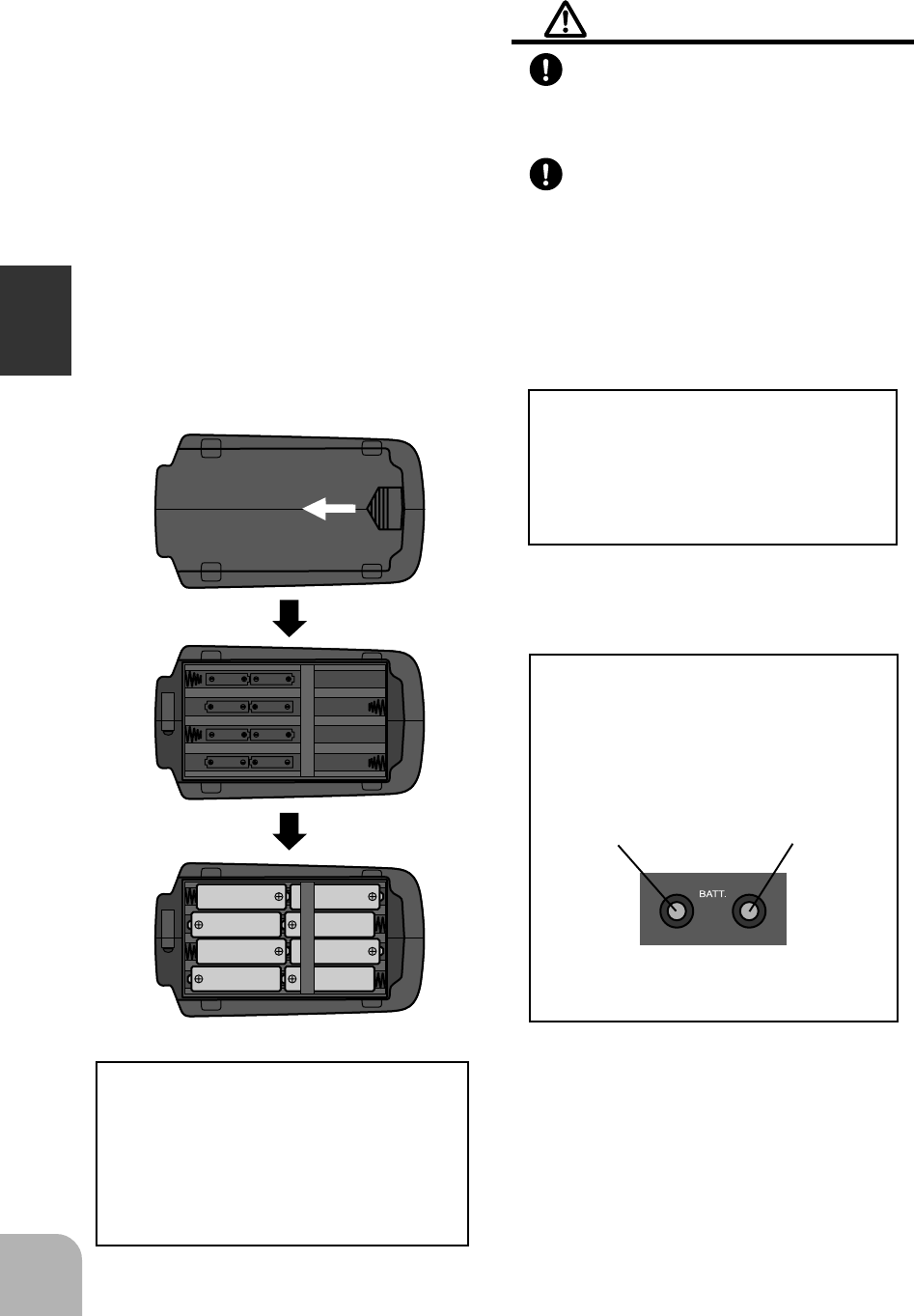
Handling Procedure For Bat-
teries (8 AA Size Batteries)
(Battery Replacement Method)
1Remove the battery cover from the
transmitter by sliding it in the direc-
tion of the arrow in the figure.
2Remove the used batteries.
3Load the new AA size batteries . Pay
very close attention to the polarity
markings and reinsert accordingly.
4Slide the battery cover back onto the
case.
(Check)
Turn the power switch on the trans-
mitter to the ON position. Check to
see if the two LEDs light.
If the LEDs fail to light, check the
batteries for insufficient contact in the
case or incorrect battery polarity.
Caution
Always be sure you reinsert the bat-
teries in the correct polarity order.
If the batteries are loaded incorrectly , the
transmitter may be damaged.
When the transmitter will not be
used for any short or long period of
time, always remove the batteries.
If the batteries do happen to leak , clean the
battery case and contacts thoroughly. Make
sure the contacts are free of corrosion.
(Battery Disposal)
Some states require special handling
when any type of battery is disposed.
Contact the State Agency responsible
for recycling hazardous waste for pro-
cedures in your area.
(Battery Alarm Display)
When the Green battery level indica-
tor (LED) goes off and the Red LED
flashes, change the batteries immedi-
ately.
OPEN
Red LED Green LED
(Battery Level Indicator)
9
Assembly / Adjustment
Assembly / Adjustment
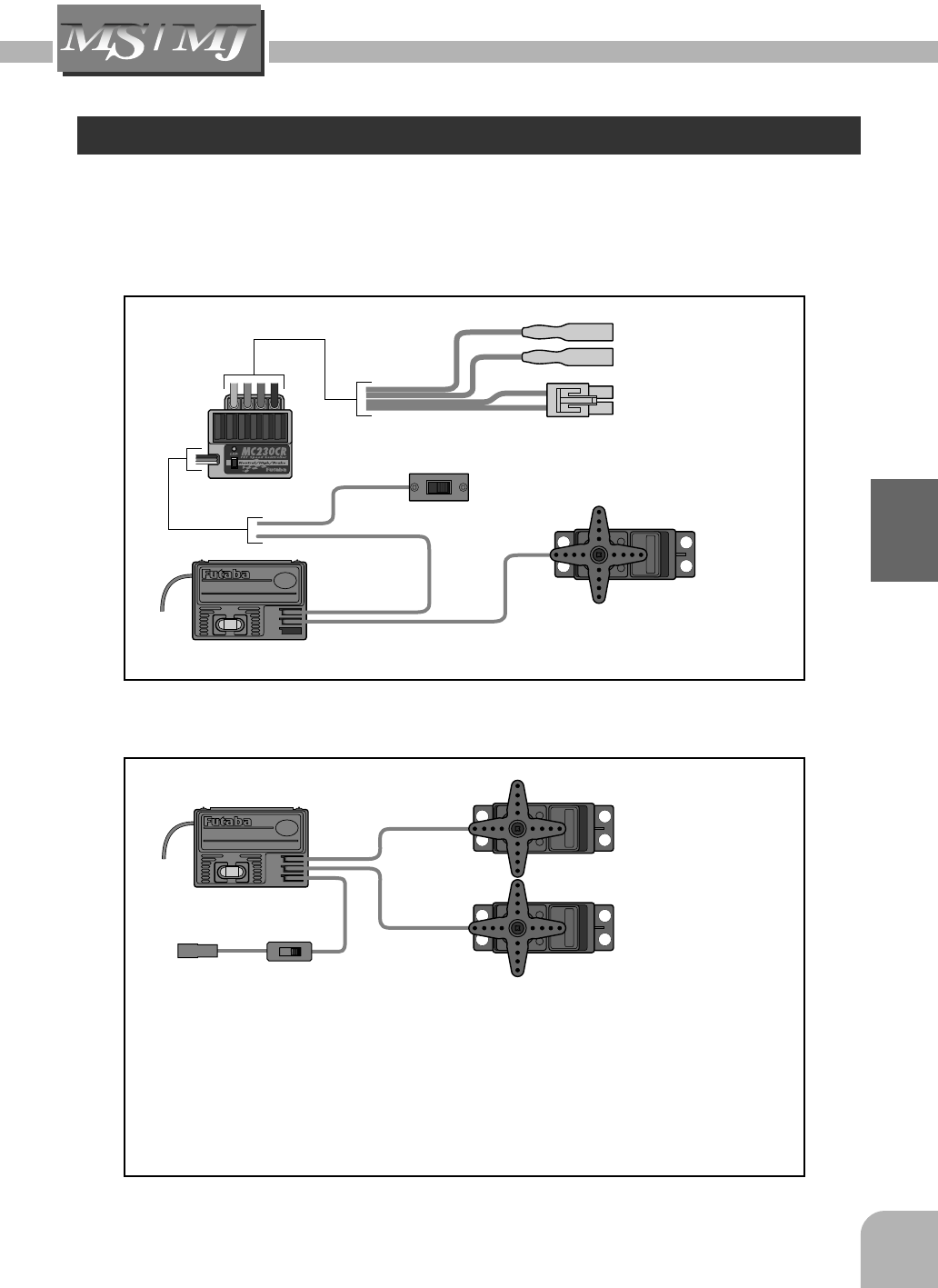
Receiver And Servo Connection
As you connect the receiver, servo's and other components, do so in accordance with the
"Assembly Precautions" listed on the next page.
FP-R122JE
AM 2 CHANNEL RECEIVER
BEC
X’TAL
CH.2
CH.1
BATT
FP-R122JE
AM 2 CHANNEL RECEIVER
BEC
X’TAL
CH.2
CH.1
BATT
Connections when a E.S.C. MC230CR or MC330CR are used.
Gas Powered Model
Steering Servo
Throttle Servo
Receiver
Receiver
Power Switch
To Receiver
Battery
(CH1)
(CH2)
(CH2)
(CH1)
(BATT)
Connect the battery in accordance with instructions provided with model you are
installing this system in.
Use the R2-BSS-N battery holder to match your application.
If your model has a mechanical type speed control (Servo Driven for electric powered
models) inspect this component for a power supply regulator or voltage dropping Diode.
These device’s will cause a voltage drop to the receiver. Be sure to remove them prior
to installation in your model.
Steering Servo
ON
OFF
E.S.C. Power Switch
Connects to Motor
Connects to Battery
10
Assembly / Adjustment
Assembly Precautions
Warning
Check Check the receiver, servos, and battery connectors, to be sure they are firmly con-
nected.
If a connector is not fully inserted, vibration may cause the connector to work loose
while the model is operating. This will result in loss of control.
Check Operate each servo horn over its full stroke and check to see that the linkage does not
bind or is not too loose.
Excessive force applied to the servo horn by binding or poor installation may lead to
servo problems and cause result in loss of control.
Prohibited
The receiver antenna may seem long. Do not cut or alter from the original length.
If the receiver antenna length is altered, the receiver will be adversely effected. The
receiver will become considerably more susceptible to interference and high fre-
quency noise which will result in loss of range and control.
Installation Note
(Electric Car's and Boat's)
Isolate the receiver from vibration by attaching to the chassis or mounting plate with
thick double sided tape.
(Gas Powered Car's and Boat's)
Isolate the receiver from vibration by wrapping it in foam rubber or similar type cush-
ioning material. Protect the unit from water damage by placing it in a plastic bag or
waterproof radio box.
The receiver contains precision electronic parts. These parts are vulnerable to vibra-
tion and shock. Any contact with moisture (water or condensation) may cause receiver
malfunction and loss of control.
Installation Note
Keep all devises that may omit high frequency noise, such as motor's, batteries, and
wiring that handle heavy current loads, at least 1/2 inch away from the receiver and
receiver antenna.
High frequency noise will cause a decrease in operating range and could cause loss of
control.
Use genuine Futaba parts only.
Use only genuine Futaba crystal set's as specified in this instruction manual.
The use of other than Futaba crystal set's will result in decrease of range as well as
loss of control. There are separate crystal's for the Transmitter and Receiver, there are
also crystal set's for AM, FM and Dual Conversion FM. Use only single conversion AM
crystal set's with this system.
Changing crystals in 72-75 MHz transmitter is illegal, however 27 MHz is allowable.
(For U.S.A.)
11
Assembly / Adjustment
Install electronic speed control heat sinks as well as other components that conduct
electricity so they can not come in contact with aluminum, carbon fiber or other mate-
rials that conduct electricity.
If for example the speed control came loose while the model was running and touched
an aluminum chassis a short circuit may occur that would cause irreparable damage to
the system as well as loss of control.
Installation Note
Noise suppression capacitors should be installed on almost all motors.
If the proper capacitors are not installed, high frequency noise will reduce range and
cause loss of control along with various other problems.
Installation Note
Inspect all linkage installations and any point where metal could come in contact with
other metal parts. Make sure these parts do not touch other metal parts under vibra-
tion.
Should a linkage or other metal parts come in contact with other metal parts under
vibration the high frequency noise generated by this contact will cause interference
and possible loss of control.
Caution
Disassembly Prohibited
Do Not disassemble any part of this system that is not specified in the instruction
manual.
Futaba will not be responsible for any damage due to improper disassembly of any
part of the radio control system.
12
Assembly / Adjustment
Digital Proportional Adjustment
*When making these settings adjustments , do so with the motor disconnected
or the engine not running.
Servo Horn Installation Instructions.
1Connect the receiver, servos, and other components and
then turn on the power switches to transmitter and receiver.
2Be sure the Steering trim and Throttle trim on the transmitter
are at their neutral position .
3At this time install the servo horn in the manner
described in the instruction manual provided
with the model this system will be used in.
Both servos will move to the neutral
position.
Reversing The Servo Operation Direction
Should the servo operate in the opposite direction required
for your application, reverse the rotation with the reversing
switch.
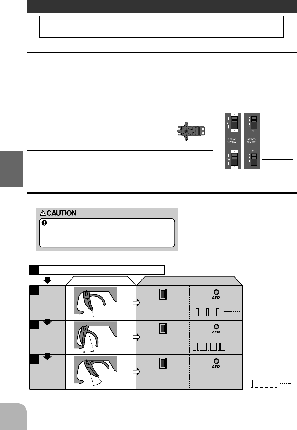
E.S.C. MC230CR / MC330CR
(Reversing Switches)
Throttle
N Side: Normal
R Side: Reverse
Steering
N Side: Normal
R Side: Reverse
(T2PH) (T2PHKA)
NEUTRAL, HIGH, AND BRAKE MAX POINTS SETTINGS
Before setting each point, set the transmitter throttle channel trim to neutral.
Turn on the power in transmitter -> amp order.
1
2
Transmitter throttle operation
・Neutral state ・Press the pushbutton switch.
(0.5 secs or longer)
(Confirmation beep sounds)
・Continuous single blink
MC230CR /MC330CR
(Pushbutton switch operation) (Checker LED)
N
N
Full High
Full brake
N
Neutral
point setting
3
・Full high state ・Press the pushbutton switch.
(Confirmation beep sounds)
・Continuous double blink
・Continuous rapid blink
High point
setting
4
・Full brake state ・Press the pushbutton switch.
(Confirmation beep sounds.)
・If the LED goes out,
setting is complete.
Brake MAX
point setting
* Since the data is read at the end of setting of all points, the points cannot be set independently.
* If the amp power was turned off during setting, the setting points cannot be memorized. (The previous settings are retained.)
* The confirmation beep sounds only when the motor was connected.
If the LED does not go off
but blinks rapidly, setting
was not performed
normally. Repeat setting
from "Neutral point
setting".
Set the steering angle adjustment function (ATV) to
100% and the ABS function and acceleration function
to OFF using the transmitter throttle channel function.
If the steering angle is too large or the ABS and acceleration
functions are on, erroneous operation may occur.
*When using the ABS function, after setting up
the MC230CR / MC330CR, stop the reverse
function, then turn on the ABS function. If the
ABS function is on, the MC230CR / MC330CR
cannot be set up correctly.
13
Description Of Functions
Description Of Functions
Steering Trim
Throttle neutral adjustments can be made moving the throttle
trim to the left or right.
Racers Tip
When using a electronic speed control set the throttle trim
to neutral and make adjustments to the speed control. On
a gas powered model set the trim to neutral and adjust the
linkage to the point where the carburetor is fully closed in
accordance with the engine instruction manual.
Trim Operation and Travel
Trim adjustments will effect the overall servo travel, check the brake side (back-
ward) movement when changes are made.
When trim movement is extreme
If you use most of the trim movement to get the servo to the neutral position , recenter the
servo horn closer to the neutral position and inspect your throttle linkage.
Throttle Trim
Steering neutral adjustments can be made by moving the
Steering trim knob to the left or right.
Racers Tip
When you install a servo always check to be sure the servo is at its neutral position.
Adjust the servo horn hole position and linkage so both are parallel. When a servo
saver is used place it as close to center position as possible. Be sure the steering
trim on the transmitter is at the neutral position.
Trim Operation And Maximum Travel
Changing the trim can effect the overall settings, when adjustments are made with
the trims recheck your installation for maximum servo travel. (Steering EPA right
side and left side).
When Trim usage is extreme
If it takes most of your trim movement to get a servo to
the neutral position, reposition the servo horn or servo
saver on the servo and inspect your linkage installation.
(Drum Type)
(Slide Type)
Carburetor Fully Closed
90°90°
Parallel
Servo Saver
Direct Servo Saver Horn
Throttle Trim
Steering Trim
Servo Reverse
This function reverses the rotation direction of the Steering
and Throttle servos.
When the trim position deviates from the center, the de-
viation will be on the opposite side when the servo is
reversed.
(Reversing Switches)
Throttle
N Side: Normal
R Side: Reverse
Steering
N Side: Normal
R Side: Reverse
(T2PH) (T2PHKA)
14
Description Of Functions
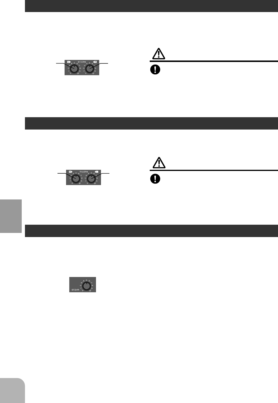
Throttle EPA (only 2PHKA)
Steering D/R (only 2PHKA)
This function is used to adjust the forward and brake side servo travel. Each direction can
be adjusted independent of each other. Use this feature to set the throttle servo travel.
Use this function to adjust the steering travel of your model. If the model understeers
(push) while cornering, add steering by turning the dial clockwise. When the model
oversteers (loose), take away steering by turning the dial counterclockwise.
Warning
Be sure that your throttle linkage does not
apply excessive force to the servo.
If your linkage installation causes an unreason-
able amount of force to be applied to the servo,
the servo may be damaged and result in loss of
control.
Steering EPA (only 2PHKA)
Use this function to limit the servo movement to the left or right. The servo travel to each
side can be independently adjusted. This feature will compensate for any difference in right
or left turning angles or radius due to the characteristics of your model.
Warning
Be sure that the steering linkage does not
bind or come in contact with any suspen-
sion parts or arms.
If unreasonable force is applied to the servo, the
servo may be damaged and result in loss of
control.
0 side: Travel Minimum
10 side: Travel Maximum
Steering EPA
Left side Right side
0 side: Travel Minimum
10 side: Travel Maximum
Throttle EPA
High side Low side
0 side: Travel Minimum
10 side: Travel Maximum
Steering D/R
15
Description Of Functions
MC230CR / MC330CR
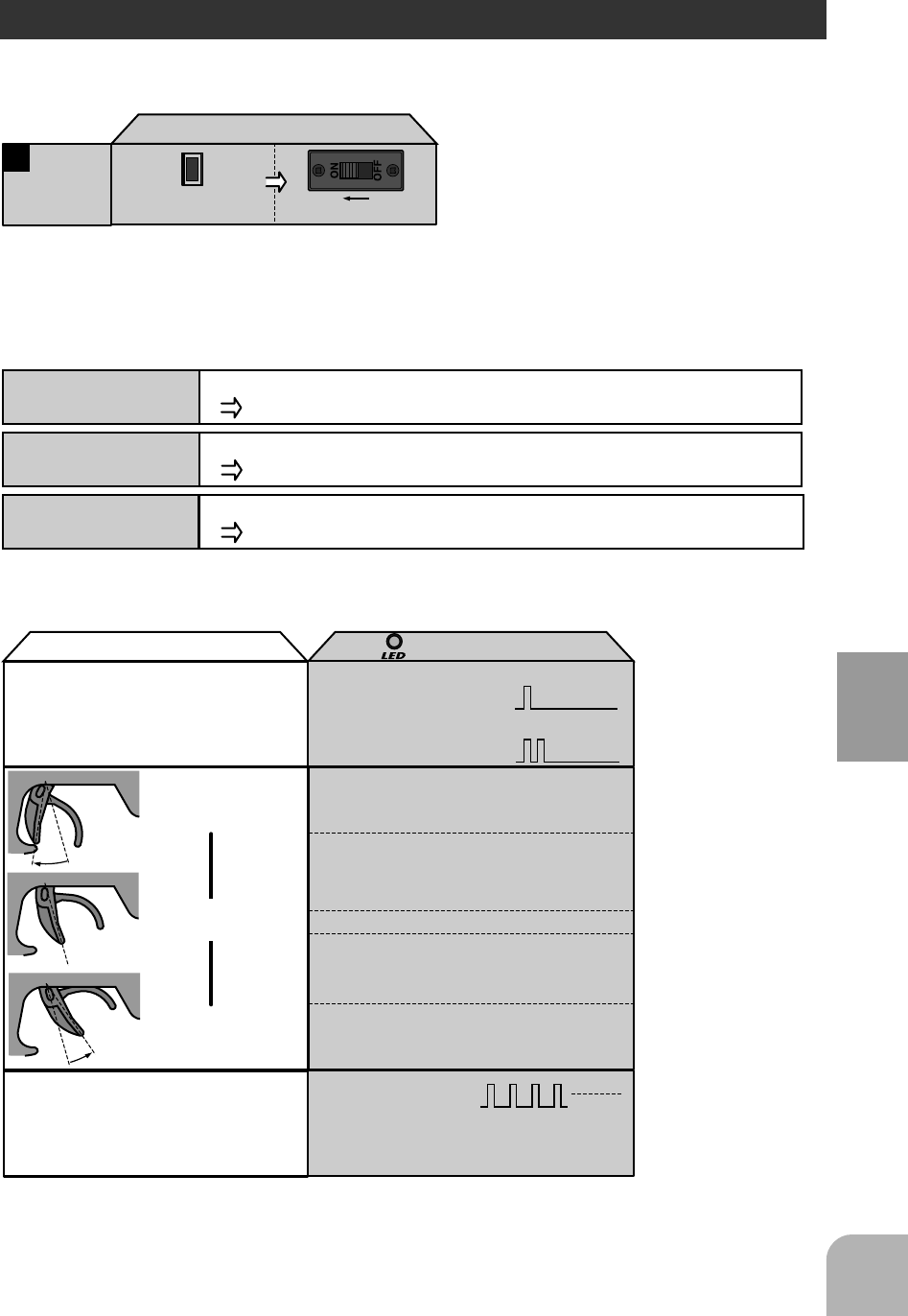
BRAKE/REVERSE OPERATING INSTRUCTIONS
Operation can be switched to reverse operation by returning the throttle trigger (or throttle stick) from the brake
position to the neutral position.
CANCELLING THE REVERSE FUNCTION
The amp reverse function can be cancelled by the following method so that the model can be used even in races
that prohibit reverse running. (Brake operation only)
While pressing
the pushbutton switch, set the power switch to ON.
ON
MC230CR / MC330CR
(Pushbutton switch operation) (Power switch)
1Reverse
function
cancellation
* When desired, you can enable the cancelled reverse
function by repeating the operation shown at the left.
(The reverse function is switched alternately.)
CHECKER LED DISPLAY
The amp operates linearly in proportion to the amount of forward, reverse, and brake operation. The amp operating
state can be checked with the checker LED as shown below.
PROTECTION CIRCUIT OPERATION
The following protection circuits are built into the MC230CR / MC330CR. When a protection circuit operates,
remove the cause before operating the model again.
Operation
Amp power ON
Checker LED display
(Reverse operation set)
Single blink
(Single confirmation beep)
(Only brake operation set)
Off
On
On
Off
Off
Double blink
(Two confirmation beeps)
Blinks. (Confirmation
beep also sounds.)
* Confirmation beep only sounds when the motor was connected.
High point
Neutral point
Brake MAX point
*Becomes brighter nearer the high
point.
*Becomes brighter nearer the
brake MAX point.
*Not used with PCM receivers.
*When the transmitter if OFF, this function is
not performed in environments such that the
servo operates erroneously.
When an overcurrent flows due to an output short circuit, etc., the overcurrent protection circuit automatically
limits the current to protects the FET.
Remove the cause of the short circuit, etc. before operating the model again.
(Amp power left on alarm)
When the transmitter power
was turned off first.
Forward
Reverse
/brake
Overcurrent
protection
When abnormal heating of the FET due to an overload, etc. is detected, the heat protector operates so that
the speed is gradually reduced.
When the FET temperature drops, the heat protector automatically resets. However, remove the cause
of the overheating before operating the model again.
Heat protector
When the Nicd battery voltage drops, this function limits the motor output current and ensures steering operation.
After the speed drops, immediately recover the vehicle.
Low voltage
operation

16
Reference
Reference
Ratings
Transmitter T2PH / T2PHKA
(2 channels, AM transmitter)
Transmitting frequency:
27, 29, 40, 41, 72 or 75 MHz
Modulation method: AM
Power requirement:
12V (penlight battery X 8)
Current drain: 250mA
Receiver R122JE
(2 channels, AM receiver)
Receiving frequency:
27, 29, 40, 41, 72 or 75 MHz
Intermediate frequency: 455kHz
Power requirement: 4.8 - 8.4V
Current drain: 30mA (at 4.8V / No signal)
Size: 47.2X33.3X17.3mm
Weight: 16.6g
Servo S3003
(standard servo)
Power requirement:
4.8V or 6V (common with receiver)
Current drain: 8mA (at 6V / Idle)
Output torque: 3.2kg-cm (at 4.8V)
Operating speed: 0.23sec/60 digree (at 4.8V)
Size: 40.4x19.8x36mm
Weight: 37.2g
E.S.C. MC230CR / MC330CR
(Electronic speed control)
Operating system: Forward, reverse, and brake
operations are all linear.
Power requirement: Nicd battery 6-7 cells
7.2 to 8.4V
PWM frequency: 1.5kHz (fixed)
Setting: One-touch input by pushbutton switch.
Set data is saved to built-in EEPROM.
Current capacity (FET rating):
Forward=90A/200A, reverse=45A/100A
Case size: 27.1x33.3x12.8mm
(excluding protruding parts)
Silicon cord gauge size:
AWG16/AWG14 equivalent
Weight: 44/45g
(including connectors and switches)
BEC voltage: 6.0V
*Specifications and ratings are subject to change without prior notice.

17
Reference
If your digital proportional R/C set does not operate, its range is short, it intermit-
tently stops operating, or it operates erroneously, take the action shown in the table
below. If this does not correct the trouble, please contact a Futaba dealer.
Check point Check item Action
Transmitter/receiver
battery Dead battery.
Incorrect loading.
Faulty contact con-
nection.
Dirty contacts.
Replace the battery. Charge the nicd
battery.
Reload the batteries in the correct
polarity.
If the contact spring is deformed,
correct it.
Wipe with a dry cloth.
Transmitter antenna Loose.
Not extended to full
length.
Screw in.
Extend fully.
Crystal Disconnected.
Wrong band.
Different from specifi-
cation.
Push in.
Match transmitter/receiver band.
Replace with specified crystal.
Connector connection Incorrect wiring.
Disconnection. Reinsert.
Push in.
Receiver antenna Close to other wiring.
Not cut?
Not bundled?
Separate from other wiring.
Request repair.
Install in accordance with instruction
manual.
Servo linkage Binding or looseness Adjust at the model side.
Motor Noise countermea-
sures. Install a noise absorbing capacitor.
Troubleshooting
FUTABA CORPORATION
Makuhari Techno Garden Bldg., B6F 1-3 Nakase, Mihama-ku, Chiba 261-8555, Japan
Phone: (043) 296-5119 Facsimile: (043) 296-5124
©FUTABA CORPORATION 2001, 07