Futaba T2PHKA-75A Radio Control Transmitter User Manual
Futaba Corporation Radio Control Transmitter Users Manual
UserManual.wiki
>
Futaba
>
T2PHKA 75A User Manual
Users Manual
Navigation menu
Upload a User Manual
Namespaces
Wiki Guide
HTML
PDF
Info
Views
User Manual
Discussion / Help
Navigation
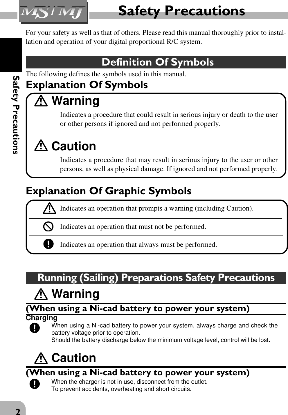
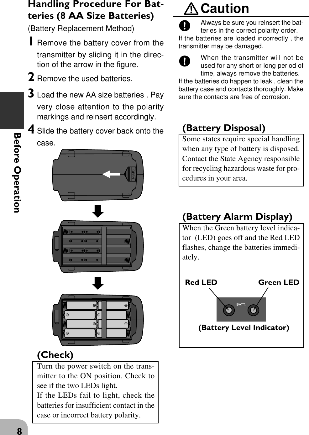
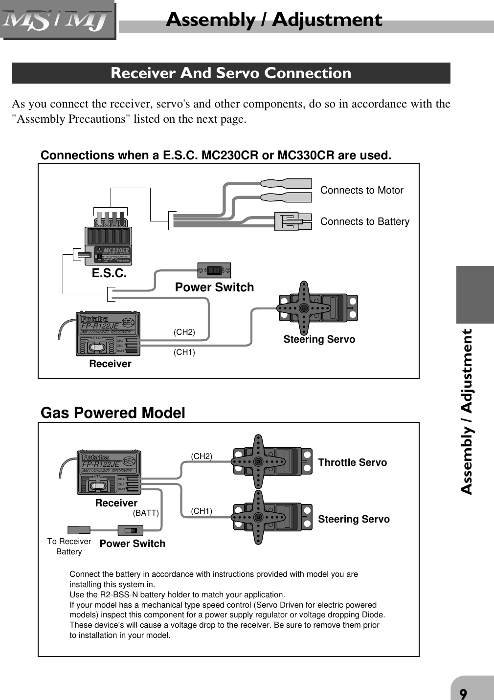
![3Safety PrecautionsRunning (Sailing) Safety PrecautionsWarningConduct TestsPrior to operation always preform a range test.Even one abnormality in the R/C system may cause loss of control.[Range Test Procedure]Have a friend hold the model, or place on a stand where the wheels or prop can notcome in contact with any object. Collapse the transmitter antenna and operate from adistance of about 10 yards. Be sure to check the movement of each servo to makesure they follow the movement of the steering wheel and throttle trigger. If the servosdo not follow the commands from the transmitter or any type of interference is de-tected, Do Not operate the model.Fully extend the transmitter antenna.If the transmitter antenna is not fully extended range will be reduced and control maybe lost.ProhibitedDo not operate two or more models on the same frequency at the same time.Operation of two or more models on the same frequency at the same time will causeinterference and loss of control of both models.AM, FM and PCM are different methods of modulation. Nonetheless the same fre-quency can not be used at the same point in time, regardless of the signal format.Do not operate outdoors on rainy daysNever operate in the rain or run through puddles.The transmitter, receiver, batteries and most servos, and speed controls are not wa-terproof. Contact with any type of moisture or immersion in water or snow will causedamage along with possible loss of control. Should any type of moisture enter anycomponent of the system immediately stop using the R/C system and return to ourservice center for inspection.ProhibitedDo not operate when visibility is limited.Should you loss sight of the model a collision or other dangerous situation may occur.ProhibitedDo not operate near people or roads.Do not operate near high tension power lines or communication broadcasting anten-nas.Prior to the operation of any model be sure the area you plan to use is safe. Be awareof all object that may be in the path of your model. Do not operate the model wherepeople or any type of moveable object could stray in the path of your model. Controlloss due to interference, component failure, loss of sight or low battery voltage couldresult in serious injury to yourself and others as well as damage to your model.ProhibitedDo not Operate your R/C system within 1 mile of another site where radio controlactivity may occur.Interference from other R/C systems will cause loss of control.](https://usermanual.wiki/Futaba/T2PHKA-75A/User-Guide-824633-Page-4.png)