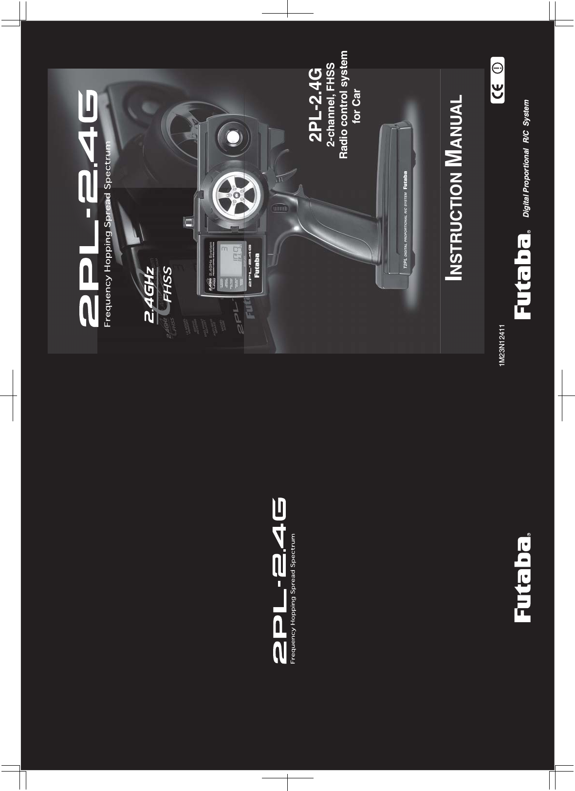
Futaba T2PL-24G Radio Control (Transmitter) User Manual
Futaba Corporation Radio Control (Transmitter)
UserManual.wiki
>
Futaba
>
T2PL 24G User Manual
User manual
Navigation menu
Upload a User Manual
Namespaces
Wiki Guide
HTML
PDF
Info
Views
User Manual
Discussion / Help
Navigation
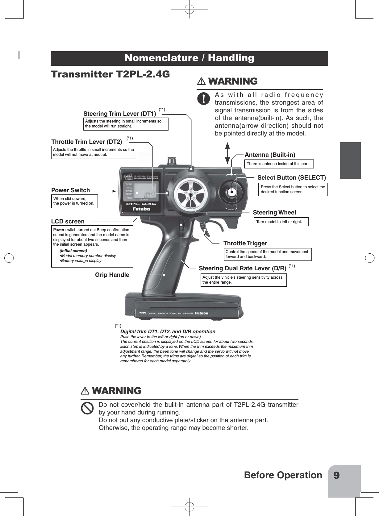
![5Safety PrecautionsOperation PrecautionsWARNING When using a Ni-cad battery to power your system, always charge and check the batteryvoltage prior to operation. Should the battery discharge below the minimum voltage level,control will be lost. Prior to operation always perform a range test. Even one abnormality in the R/C systemmay cause loss of control.[Range Test Procedure]Have a friend hold the model, or place on a stand where the wheels or prop can not comein contact with any object. Operate from a distance of about 100 feet. Be sure to check themovement of each servo to make sure it follows the movement of the steering wheel andthrottle trigger. If the servos do not follow the commands from the transmitter or any type ofinterference is detected, Do Not operate the model. Never operate in the rain or run through puddles.The transmitter, receiver, batteries and most servos, and speed controls are not waterproof.Contact with any type of moisture or immersion in water or snow will cause damage alongwith possible loss of control. Should any type of moisture enter any component of the sys-tem, immediately stop using the R/C system and return it to our service center for inspec-tion. Do not operate when visibility is limited.Should you lose sight of the model, a collision or other dangerous situation may occur. Do not operate near people or roads.Do not operate on any pond when boats are present.Do not operate near high tension power lines or communication broadcasting antennas.Prior to the operation of any model be sure the area you plan to use is safe. Be aware of allobjects that may be in the path of your model. Do not operate the model where people orany type of moveable object could stray in the path of your model. Control loss due to inter-ference, component failure, loss of sight or low battery voltage could result in serious injuryto yourself and others as well as damage to your model. Do not operate when you are tired, not feeling well or under the influence of alcohol ordrugs.Your judgment is impaired and could result in a dangerous situation that may cause seriousinjury to yourself and others. (Turning on the power switches)Always check the throttle trigger on the transmitter to be sure it is at the neutral position.1. Turn on the transmitter power switch.2. Turn on the receiver or speed control power switch.(Turning off the power switches)Always be sure the engine is not running or the motor is stopped.1. Turn off the receiver or speed control power switch.2. Then turn off the transmitter power switch.If the power switches are turned off in the opposite order the model may unexpectedly runout of control and cause a very dangerous situation.](https://usermanual.wiki/Futaba/T2PL-24G/User-Guide-1153443-Page-5.png)
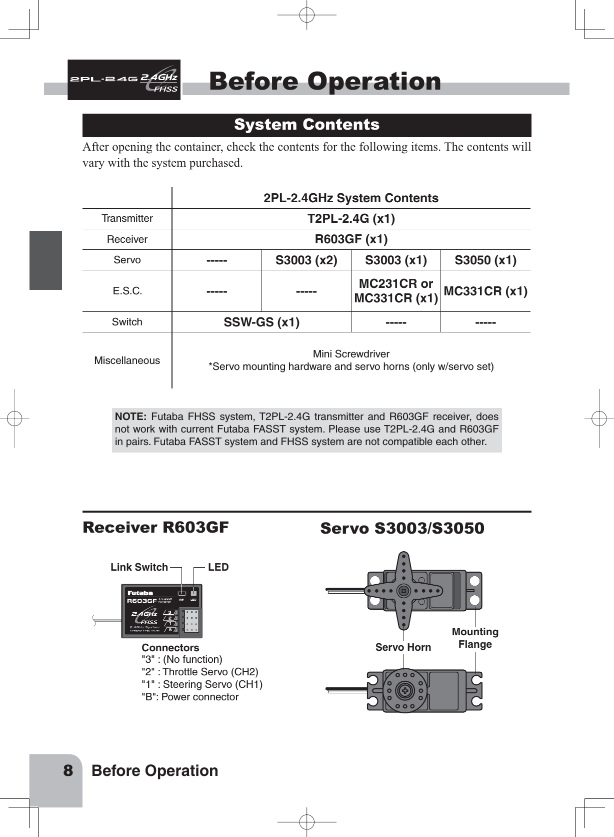
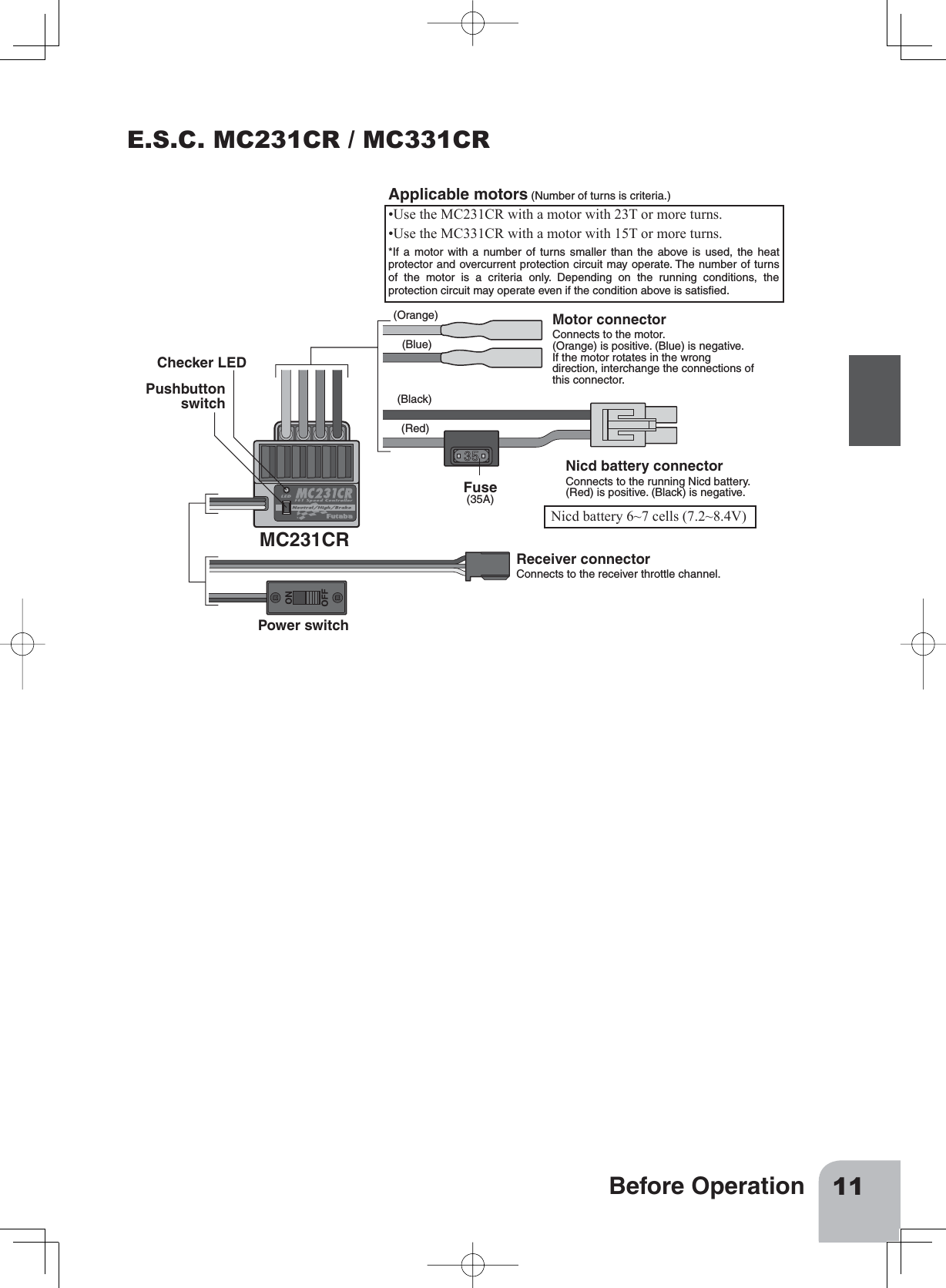
![22 ReferenceReferenceRatings Communication method:One-way operation systemMaximum operating range:80m (Optimum condition)For safety: F/S (Throttle), ID (About 4 billion ways of pair LGHQWL¿FDWLRQVTransmitter T2PL-2.4G(FHSS system, wheel type, 2 channels)Transmitting frequency: 2.4GHz bandPower requirement: (Dry cell battery) Penlight x 4(6V)Current drain: 100mA or lessTransmission antenna: ȜGLSROH%XLOWLQReceiver R603GF:(FHSS system, 3 channels)Power requirement: 4.8V or 6V NiCd batterySize:26x39x10mm (excluding a projection part)Weight: 8gServo S3003(Standard servo)Power requirement: 6V (common with receiver) Current drain: 8mA (at 6V / Idle) Output torque: 4.1kg-cm (57in.-oz.) at 6V Operating speed: 0.19sec/60 degree at 6VSize:40.4x19.8x36mm (1.59x0.78x1.42in.)Weight: 37.2g (1.31oz.)Servo S3050(Standard digital servo)Power requirement: 6V (common with receiver) Current drain: 8mA (at 6V / Idle) Output torque: 6.5kg-cm (90.3oz.-in.) at 6V Operating speed: 0.16sec/60 degree at 6VSize:40.0x20.0x38.1mm (1.57x0.79x1.50in.)Weight: 49g (1.72oz.)E.S.C. MC231CR / MC331CR(Electronic speed control) Operating system: Forward, reverse, and brake operations are all linear.Power requirement: Nicd battery 6-7 cells (7.2 to 8.4V)PWM frequency: N+]¿[HGSetting:One-touch input by pushbutton switch. Set data is saved to built-in EEPROM.Current capacity (FET rating):Forward=90A/200A, reverse=45A/100ASize:27.1x33.3x12.8mm (1.07x1.31x0.50in.) (excluding protruding parts)Silicon cord gauge size:AWG16/AWG14 equivalentWeight: 44/45g (1.55/1.59oz.)(including connectors and switches)BEC voltage: 6.0V*Specifications and ratings are subject to change without prior notice.NOTE: Futaba FHSS system, T2PL-2.4G transmitter and R603GF receiver, doesnot work with current Futaba FASST system. Please use T2PL-2.4G and R603GFin pairs. Futaba FASST system and FHSS system are not compatible each other.](https://usermanual.wiki/Futaba/T2PL-24G/User-Guide-1153443-Page-22.png)