Futaba T2PSK-24G Radio Control User Manual
Futaba Corporation Radio Control
UserManual.wiki
>
Futaba
>
T2PSK 24G User Manual
User Manual
Navigation menu
Upload a User Manual
Namespaces
Wiki Guide
HTML
PDF
Info
Views
User Manual
Discussion / Help
Navigation

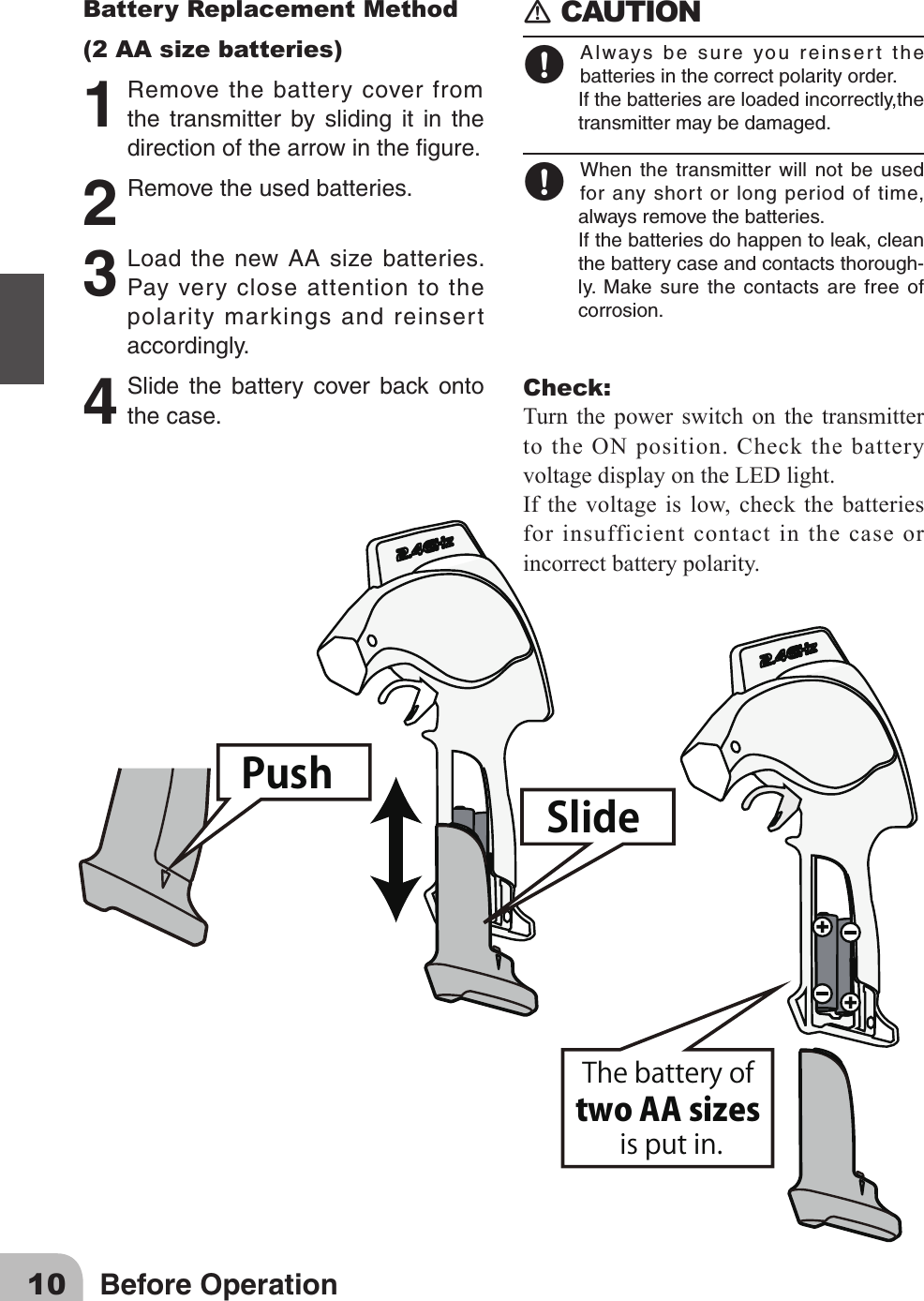
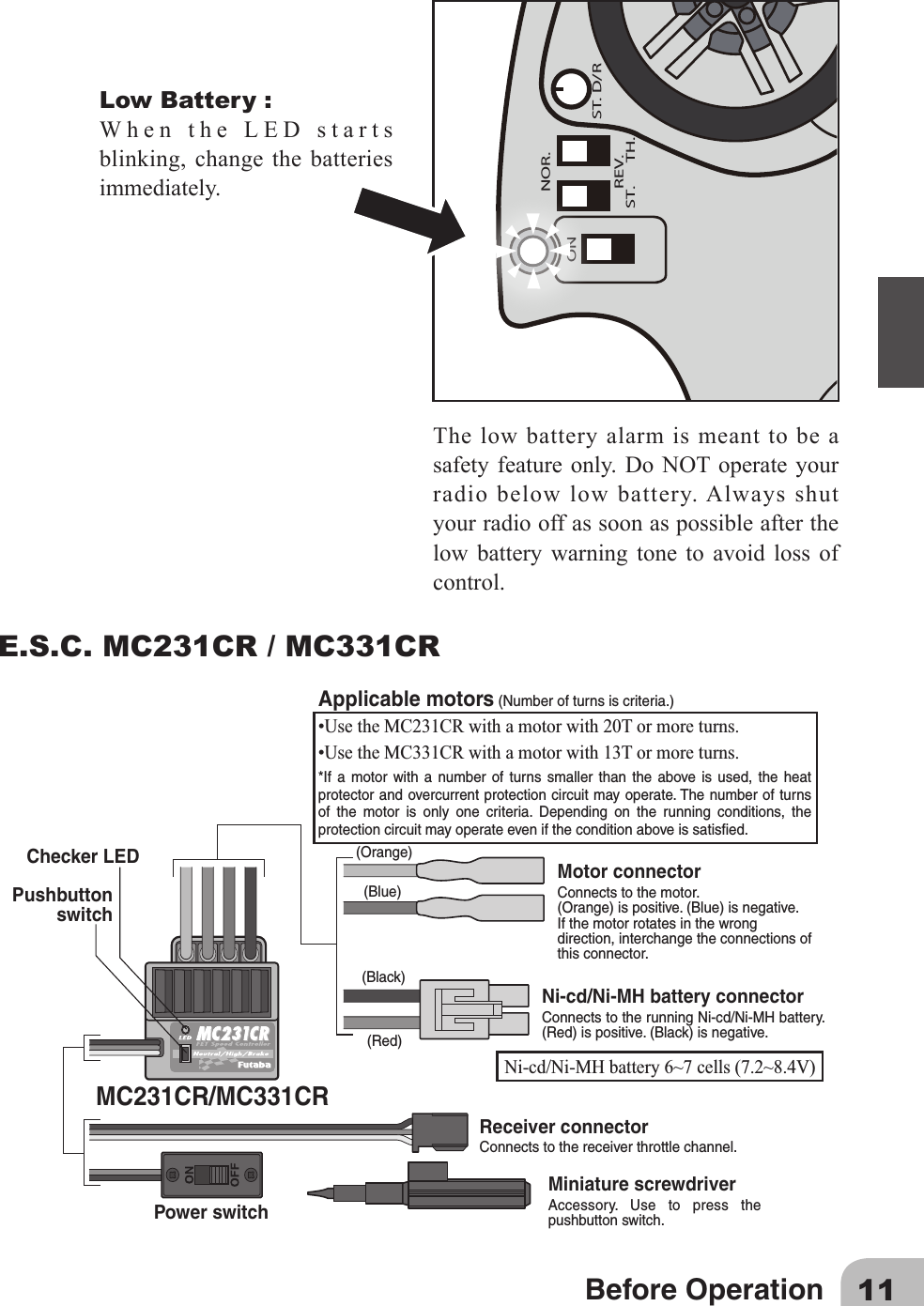
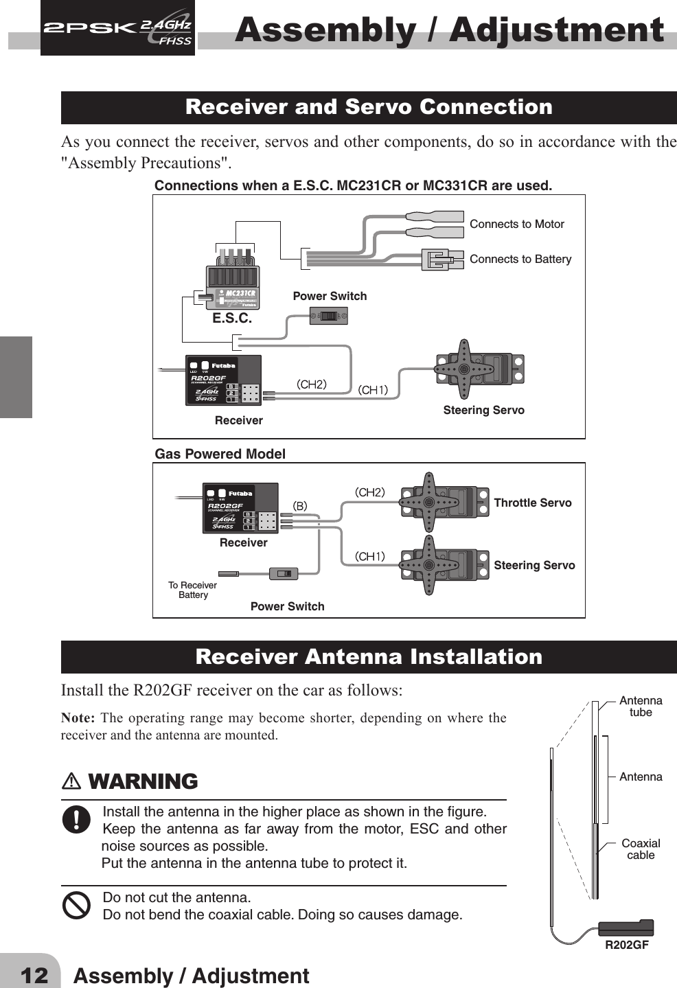
![5Safety PrecautionsOperation PrecautionsWARNINGWhen using a Ni-Cd/Ni-MH battery to power your system, always charge and check thebatteryvoltagepriortooperation.Shouldthebatterydischargebelowtheminimumvoltagelevel,controlwillbelost.Prior to operationalwaysperform arange test. Evenone abnormalityin the R/Csystemmaycauselossofcontrol.[Range Test Procedure]Haveafriendholdthemodel,orplaceonastandwherethewheelsorpropcannotcomeincontactwithanyobject.Operatefromadistanceofabout100feet.Besuretocheckthemovementofeachservotomakesureitfollowsthemovementofthesteeringwheelandthrottletrigger.Iftheservosdonotfollowthecommandsfromthetransmitteroranytypeofinterferenceisdetected,DoNotoperatethemodel.Neveroperateintherainorrunthroughpuddles.The transmitter, receiver, batteries and most servos, and speed controls are not water-proof.Contactwithanytypeofmoistureorimmersioninwaterorsnowwillcausedamagealong with possible loss of control. Should any type of moisture enter any component ofthesystem,immediatelystopusingtheR/Csystemandreturnittoourservicecenterforinspection.Donotoperatewhenvisibilityislimited.Shouldyoulosesightofthemodel,acollisionorotherdangeroussituationmayoccur.Donotoperatenearpeopleorroads.Donotoperateonanypondwhenboatsarepresent.Donotoperatenearhightensionpowerlinesorcommunicationbroadcastingantennas.Priortotheoperationofanymodelbesuretheareayouplantouseissafe.Beawareofallobjectsthatmaybeinthepathofyourmodel.Donotoperatethemodelwherepeopleoranytypeofmoveableobjectcouldstrayinthepathofyourmodel.Controllossduetointer-ference,componentfailure,lossofsightorlowbatteryvoltagecouldresultinseriousinjurytoyourselfandothersaswellasdamagetoyourmodel.Do not operate when you are tired, not feeling well or under the inuence of alcohol ordrugs.Yourjudgmentisimpairedandcouldresultinadangeroussituationthatmaycauseseriousinjurytoyourselfandothers.(Turning on the power switches)Alwayscheckthethrottletriggeronthetransmittertobesureitisattheneutralposition.1.Turnonthetransmitterpowerswitch.2.Turnonthereceiverorspeedcontrolpowerswitch.(Turning off the power switches)Alwaysbesuretheengineisnotrunningorthemotorisstopped.1.Turnoffthereceiverorspeedcontrolpowerswitch.2.Thenturnoffthetransmitterpowerswitch.Ifthepowerswitchesareturnedoffintheoppositeorderthemodelmayunexpectedlyrunoutofcontrolandcauseaverydangeroussituation.](https://usermanual.wiki/Futaba/T2PSK-24G/User-Guide-1731673-Page-5.png)