User Manual-1009

TH.
ON
REV.
ST.
NOR.
ST.
TH.
TRIM
TH. D/R
R
Digital Proportional R/C System
2PSK
2-channel, FHSS
Radio control system
for Car
INSTRUCTION MANUAL

Thank you for purchasing a Futaba FHSS 2PSK 2.4GHz system.
This system is based on the combination of the newly developed 2.4GHz transmitter and
its corresponding receiver. Before using your 2PSK 2.4GHz system, read this manual
carefully and use your R/C set safely.
After reading this manual, store it in a safe place.
FHSS 2PSK 2.4GHz system
•Frequencychannelsettingunnecessary:Shiftingthechannelswithinthe2.4GHzbandautomatically,this
system minimizes the interference from other 2.4GHz systems.
•FHSS(FrequencyHoppingSpreadSpectrum)minimizesinterferencefromother2.4GHzsystems.This
system is not compatible with FASST.
Application, Export, and Modication
1. This product may be used for models only. It is not intended for use in any application other than the
control of models for hobby and recreational purposes.
2.Exportationprecautions:
(a)Whenthisproductisexportedfromthecountryofmanufacture,itsuseistobeapprovedbythelaws
governingthe countryof destinationwhich governdevices thatemit radiofrequencies. Ifthis productis
then re-exported to other countries, it may be subject to restrictions on such export. Prior approval of the
appropriategovernmentauthoritiesmayberequired.Ifyouhavepurchasedthisproductfromanexporter
outside your country, and not the authorized Futaba distributor in your country, please contact the seller
immediately to determine if such export regulations have been met.
(b)UseofthisproductwithotherthanmodelsmayberestrictedbyExportandTradeControlRegulations,
and an application for export approval must be submitted.
3.Modification,adjustment,andreplacementofparts:Futabaisnotresponsibleforunauthorized
modication,adjustment,andreplacementofpartsonT2PSK.Anysuchchangesmayvoidthewarranty.
4.Changesormodicationsnotexpresslyapprovedbythepartyresponsibleforcompliancecouldvoidthe
user’sauthoritytooperatetheequipment.
Compliance Information Statement (for U.S.A.)
This device, trade name Futaba Corporation of America, model number T2PSK-2.4G, complies with part
15oftheFCCRules.Operationissubjecttothefollowingtwoconditions:
(1)Thisdevicemaynotcauseharmfulinterference,and
(2) This device must accept any interference received, including interference that may cause undesired
operation.
(3) This device complies with FCC radiation exposure limits set forth for an uncontrolled environment.
Thisequipmentshouldbeinstalledandoperatedwithminimumdistance20cmbetweentheradiatorand
your body.
Theresponsiblepartyofthisdevicecomplianceis:
3002NApolloDriveSuite1,Champaign,IL61822U.S.A.
TEL(217)398-8970orE-mail:support@futaba-rc.com(Support)
TEL(217)398-0007orE-mail:service@futaba-rc.com(Service)
Battery Recycling (for U.S.A.)
The RBRCTM SEAL on the (easily removable) nickel-cadmium battery contained in Futaba
products indicates that Futaba Corporation of America is voluntarily participating in an
industry program to collect and recycle these batteries at the end of their useful lives, when
taken out of service within the United States.The RBRCTM program provides a convenient
alternative to placing used nickel-cadmium batteries into the trash or municipal waste system,
which is illegal in some areas.
You may contact your local recycling center for information on where to return the spent battery. Please
call1-800-8-BATTERYforinformationonNi-Cdbatteryrecyclinginyourarea.FutabaCorporation
of America's involvement in this program is part of its commitment to protecting our environment and
conserving natural resources.
RBRCTM is a trademark of the Rechargeable Battery Recycling Corporation.

3
Safety Precautions ............................. 4
Definition of Symbols ............................................................ 4
2.4GHz System Precautions ................................................. 4
Operation Precautions .......................................................... 5
Storage and Disposal Safety Precautions ........................... 6
Other Safety Precautions ...................................................... 7
Before Operation ................................ 8
System Contents .................................................................... 8
Nomenclature / Handling ....................................................... 9
Assembly / Adjustment ..................... 12
Receiver and Servo Connection ......................................... 12
Receiver Antenna Installation ............................................. 12
Assembly Precautions ........................................................ 13
How to Link Transmitter and Receiver ............................... 14
Fail Safe Function (F/S) ....................................................... 14
Transmitter Set-Up Procedures .......................................... 15
2PSK-2.4G Functions ........................ 16
Steering Trim ....................................................................... 16
Throttle Trim ........................................................................ 16
Steering Dual Rates (D/R) .................................................. 17
Steering Servo Reversing .................................................. 17
Throttle Servo Reversing ................................................... 17
MC231CR/MC331CR ............................................................ 18
Reference .......................................... 19
Ratings .................................................................................. 19
Troubleshooting ................................................................... 20
Error Displays ...................................................................... 21
When Requesting Repair ..................................................... 21
Table of Contens
Warning: This product contains a chemical known to cause cancer and birth defects (or
other reproductive harm).
•Nopartofthismanualmaybereproducedinanyformwithoutpriorpermission.
•Thecontentsofthismanualaresubjecttochangewithoutpriornotice.
•This manual has been carefully written. Please write to Futaba if you feel that any corrections or
claricationsshouldbemade.
•Futabaisnotresponsiblefortheuseofthisproduct.
Safety
Precautions
Before
Operation
Assembly /
Adjustment
2PSK-2.4G
Functions
Reference
4Safety Precautions
Safety Precautions
2.4GHz System Precautions
WARNING
Donotcover/holdthebuilt-inantennapartofT2PSK-2.4Gtransmitterbyyourhandduring
running.Donotputanyconductiveplate/stickerontheantennapart.
Otherwise,theoperatingrangemaybecomeshorter.
Donotperformthelinkingprocedurewhilemotor'smainwireisconnectedortheengineis
operatingasitmayresultinseriousinjury.
Whilethelinkingisdone,pleasecyclereceiverpowerandcheckifthereceivertobelinked
isreallyunderthecontrolbythetransmittertobelinked.
AlwaysuseR202GF4.8V~7.4VrechargeablebatteryorregulatedoutputfromESC.
Usingdrycellbatteriesmaycausethesystemtomalfunction.
WhenusinganESC,besurethattheregulatedoutputcapacitymeetsyourusagecondi-
tion.
Inordertomaintaincompletecontrolofyourcar/boatitisimportantthatitremainsvisible
at all times. Running behind large objects is not suggested. Doing so may result in the
reductionofthequalityoftheradiofrequencylinktothemodel.
For your safety as well as that of others, please read this manual thoroughly prior to
installation and operation of your digital proportional R/C system.
Denition of Symbols
Thefollowingdenesthesymbolsusedinthismanual.
Explanation of Symbols
DANGER Procedureswhichmayleadtoadangerousconditionandcausedeathor
seriousinjurytotheuserifnotcarriedoutproperly.
WARNING
Procedureswhichmayleadtoadangerousconditionorcausedeathor
seriousinjurytotheuserifnotcarriedoutproperly,orprocedureswhere
theprobabilityofsupercialinjuryorphysicaldamageishigh.
CAUTION Procedureswherethepossibilityofseriousinjurytotheuserissmall,but
thereisadangerofinjury,orphysicaldamage,ifnotcarriedoutproperly.
Explanation of Graphic Symbols
Indicatesanoperationthatpromptsawarning(includingCaution).
Indicatesanoperationthatmustnotbeperformed.
Indicatesanoperationthatalwaysmustbeperformed.

5
Safety Precautions
Operation Precautions
WARNING
When using a Ni-Cd/Ni-MH battery to power your system, always charge and check the
batteryvoltagepriortooperation.Shouldthebatterydischargebelowtheminimumvoltage
level,controlwillbelost.
Prior to operationalwaysperformarangetest. Evenone abnormality in theR/Csystem
maycauselossofcontrol.
[Range Test Procedure]
Haveafriendholdthemodel,orplaceonastandwherethewheelsorpropcannotcome
incontactwithanyobject.Operatefromadistanceofabout100feet.Besuretocheckthe
movementofeachservotomakesureitfollowsthemovementofthesteeringwheeland
throttletrigger.Iftheservosdonotfollowthecommandsfromthetransmitteroranytypeof
interferenceisdetected,DoNotoperatethemodel.
Neveroperateintherainorrunthroughpuddles.
The transmitter, receiver, batteries and most servos, and speed controls are not water-
proof.Contactwithanytypeofmoistureorimmersioninwaterorsnowwillcausedamage
along with possible loss of control. Should any type of moisture enter any component of
thesystem,immediatelystopusingtheR/Csystemandreturnittoourservicecenterfor
inspection.
Donotoperatewhenvisibilityislimited.
Shouldyoulosesightofthemodel,acollisionorotherdangeroussituationmayoccur.
Donotoperatenearpeopleorroads.
Donotoperateonanypondwhenboatsarepresent.
Donotoperatenearhightensionpowerlinesorcommunicationbroadcastingantennas.
Priortotheoperationofanymodelbesuretheareayouplantouseissafe.Beawareofall
objectsthatmaybeinthepathofyourmodel.Donotoperatethemodelwherepeopleor
anytypeofmoveableobjectcouldstrayinthepathofyourmodel.Controllossduetointer-
ference,componentfailure,lossofsightorlowbatteryvoltagecouldresultinseriousinjury
toyourselfandothersaswellasdamagetoyourmodel.
Do not operate when you are tired, not feeling well or under the inuence of alcohol or
drugs.
Yourjudgmentisimpairedandcouldresultinadangeroussituationthatmaycauseserious
injurytoyourselfandothers.
(Turning on the power switches)
Alwayscheckthethrottletriggeronthetransmittertobesureitisattheneutralposition.
1.Turnonthetransmitterpowerswitch.
2.Turnonthereceiverorspeedcontrolpowerswitch.
(Turning off the power switches)
Alwaysbesuretheengineisnotrunningorthemotorisstopped.
1.Turnoffthereceiverorspeedcontrolpowerswitch.
2.Thenturnoffthetransmitterpowerswitch.
Ifthepowerswitchesareturnedoffintheoppositeorderthemodelmayunexpectedlyrun
outofcontrolandcauseaverydangeroussituation.

6Safety Precautions
Makeall adjustmentstothe radiocontrolsystem with engine notrunning, ortheelectric
motordisconnected.
Iftheengineisrunningorthemotorisconnectedwhileadjustmentsaremade,themodel
mayrunoutofcontrol.
Removethe main batterysourcefrom electricpoweredmodelswhen theyare not being
used.
Shouldyouaccidentallyleavethereceiverswitchon,themodelcouldrunoutofcontrol.
(Fail safe function)
Beforerunning(cruising),checkthefailsafefunction.
Check Method:
Beforestartingtheengine,checkthefailsafefunctionasfollows:
1.Turnonthetransmitterandreceiverpowerswitches.
2.Turnoffthetransmitterpowerswitch.
3.Checkifthefailsafefunctionmovestheservostothepresetpositionwhenreceptionfails.
Thefailsafefunctionisasafetyfeaturethatminimizessetdamagebymovingtheservos
toapresetpositionwhenreceptionfails.However,ifsettoadangerousposition,ithasthe
oppositeeffect.
Setting example:Throttleidleorbrakeposition
CAUTION
Donottouchtheengine,motor,speedcontroloranypartofthemodelthatwillgenerate
heatwhilerunning.
Touchinghotpartswillresultinseriousburns.
Whenthechargerisnot inuse,disconnectitfromthe outlet.Thiswillpreventaccidents,
overheatingandshortcircuits.
Storage and Disposal Safety Precautions
WARNING
Attheendofaday'soperation,storethesystemwithNi-Cd/Ni-MHbatterydischarged.Be
suretorechargethesystembeforeitisusedagain.
Youshouldfullydischargeyoursystem'sbatteriesperiodicallytopreventaconditioncalled
"memory". Forexample,if youonlymaketworunsina dayoryouregularlyusea small
amountofbattery'scapacity,thememoryeffectcanreducetheactualcapacityevenifthe
batteryischargedfortherecommendedamountoftime.
DonotthrowaNi-Cd/Ni-MHbatteryintoare.Donotdisassembleorattempttorepaira
Ni-Cd/Ni-MHbatterypack.
Overheating,damageandacidleakagemayleadtoburns,lossofeyesightaswellasnu-
merousother typesof injuries.TheelectrolyteinNi-Cd/Ni-MHbatteriesis astrong alkali.
Shouldyougeteventhesmallestamountoftheelectrolyteinyoureyes,DoNotrub.Wash
immediately with water, and seek medical attention at once.The electrolyte can cause
blindness.Ifelectrolytecomesincontactwithyourskinorclothes,washwithwaterimmedi-
ately.

7
Safety Precautions
Other Safety Precautions
CAUTION
Whenoperatingtwoormoremodelsatthesametime,haveathirdpersonactasaspotter.
Theywillbeinchargeofsafetyandyoushouldfollowtheirinstructions.
Beginnersshouldreceiveinstructionsregardingsafetyandoperationfromanexperienced
modeler.
AlwaysuseonlygenuineFutabatransmitter,receivers,servos,andelectronicspeed
controls,alongwithotheroptionalpartsandcomponents.
Futaba will not be held responsible for damages caused by other than genuine Futaba
parts and components. Use only genuine Futaba parts and components listed in the in-
structionmanualandcatalog.
DonotshortcircuittheNi-Cd/Ni-MHbatteryterminals.
Short circuiting the terminals will lead to sparks and overheating and could cause a re
andburnsaswell.
Donotexposeplasticpartstofuel,motorspray,wasteoilorexhaust.
Thefuel,motorspray,wasteoilandexhaustwillpenetrateanddamagetheplastic.
<Ni-Cd/Ni-MH Battery Electrolyte>
TheelectrolyteinNi-Cd/Ni-MHbatteriesisastrongalkali.Shouldyougeteventhesmallestamountofthe
electrolyteinyoureyes,DONOTRUB.Washimmediatelywithwaterandseekmedicalattentionatonce.
The electrolyte can cause blindness. If electrolyte comes in contact with your skin or clothes, wash with
water immediately.
Donotleavetheradiosystemormodelswithinthereachofsmallchildren.Asmallchildmay
accidentallyoperatethesystem.Thiscouldcauseadangeroussituationandinjuries.Ni-Cd/
Ni-MHbatteriescanbeverydangerouswhenmishandledandcausechemicaldamage.
CAUTION
DonotstoreyourR/Csystemwhereitwillbeexposedtothefollowingconditions.
•Extremeheatorcoldness
•Exposedtodirectsunlight
•Wherehumidityishigh
•Wherevibrationisprevalent
•Wheredustisprevalent
•Wherethereissteamandcondensation
StoringyourR/Csystemunderadverseconditionscouldcausedeformationandnumerous
otherproblemswithoperation.
Ifthesystemwillnotbeusedforalongperiodoftime,removethebatteriesfromthemodel
andstoreinacool,dryplace.
Ifthebatteriesareleftinthemodel,electrolytemayleakanddamagethemodel.
<Ni-Cd/Ni-MH Battery Recycling>
AusedNi-Cd/Ni-MHbatteryisvaluableresource.Insulatethebatteryterminalsanddisposeofthebattery
by taking it to a battery recycling center.
8Before Operation
Before Operation
System Contents
After opening the container, check the contents for the following items. The contents will
vary with the system purchased.
2PSK-2.4GHz System Contents
Transmitter T2PSK-2.4G (x1)
Receiver R202GF (x1)
Servo ----- S3003 (x2) S3003 (x1) S3050 (x1)
E.S.C. ----- ----- MC231CR or
MC331CR (x1) MC331CR (x1)
Switch SSW-GS (x1) ----- -----
Miscellaneous MiniScrewdriver
*Servomountinghardwareandservohorns(onlyw/servoset)
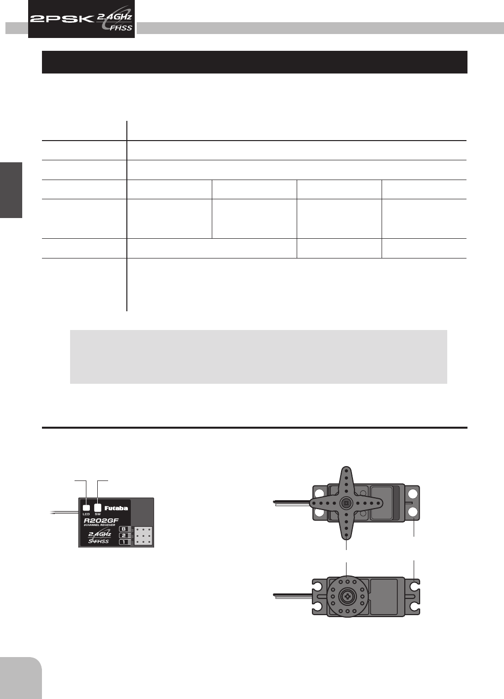
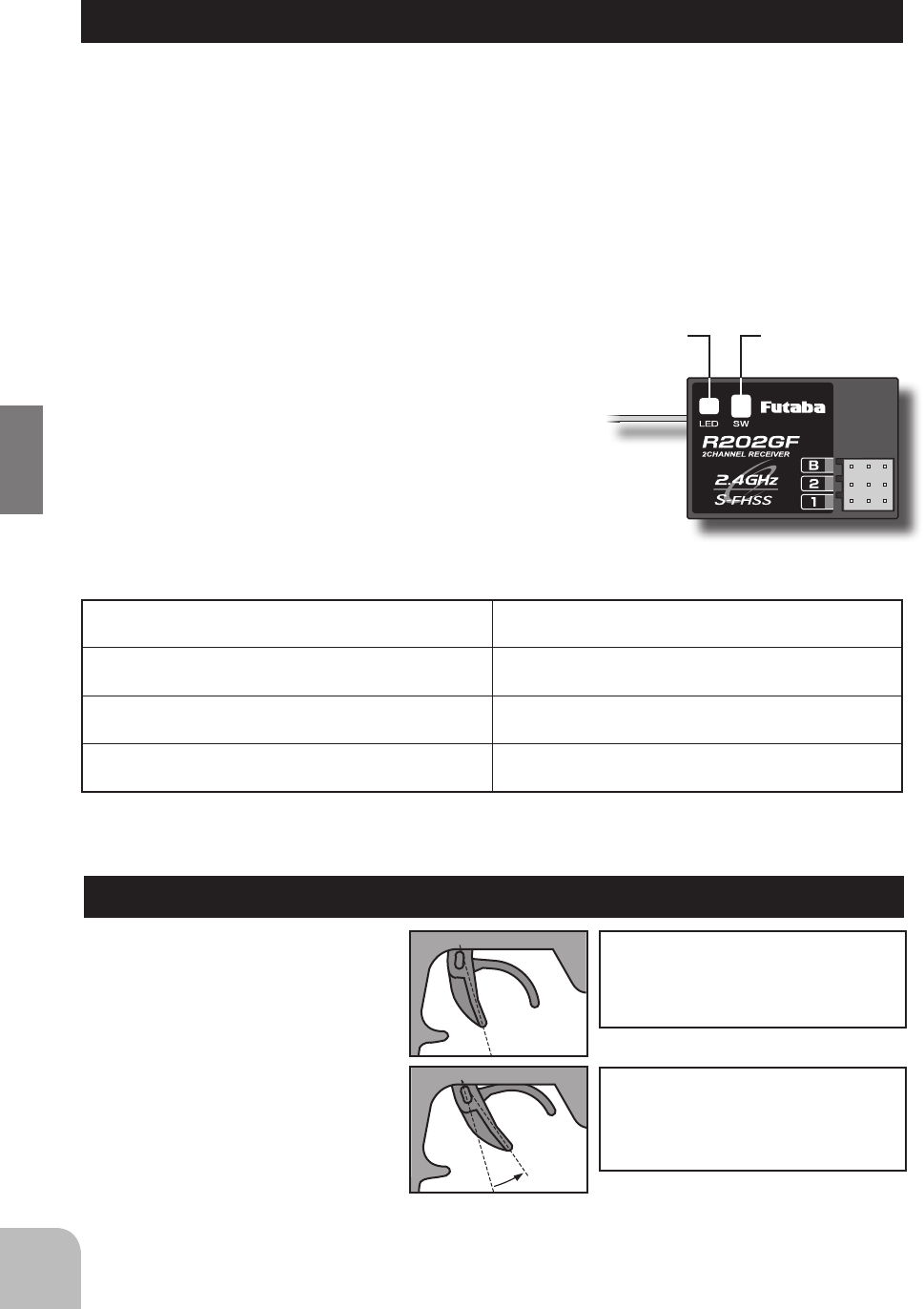
Receiver R202GF Servo S3003/S3050
Connectors
"2":ThrottleServo(CH2)
"1":SteeringServo(CH1)
"B":Powerconnector
Link SwitchLED
Servo Horn
Mounting
Flange
NOTE: Futaba FHSS system,T2PSK-2.4G transmitter and R202GF receiver, does
notworkwithcurrentFutabaFASSTsystems.PleaseuseT2PSK-2.4GandR202GF
inpairs.FutabaFASSTsystemandFHSSsystemarenotcompatibleeachother.
9
Before Operation
TH.
ON
REV.
ST.
NOR.
ST.
TH.
TRIM
ST. D/R
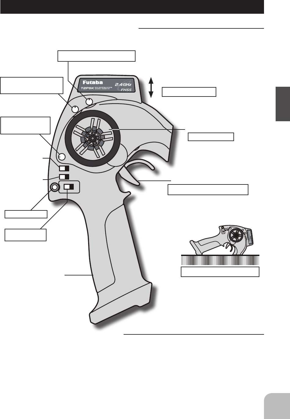
Transmitter T2PSK-2.4G
Nomenclature / Handling
WARNING
Donotcover/holdthebuilt-inantennapartof
T2PSK-2.4Gtransmitterbyyourhandduring
running.
Donotputanyconductiveplate/stickeronthe
antennapart.
Otherwise,theoperatingrangemaybecome
shorter.
WARNING
Aswithallradiofrequency
transmissions,thestrongestareaof
signaltransmissionisfromthesides
oftheantenna(built-in).Assuch,the
antenna(arrow direction) should not be
pointeddirectlyatthemodel.
Grip Handle
Throttle Trigger
Steering Dual Rate
Dial (D/R)
Antenna (Built-in)
Throttle Servo
Reversing Switch
Steering Servo
Reversing Switch
Steering Wheel
Power Switch
Whenslidupward,
thepoweristurnedon.
LED Light
ItblinksatLowBattery.
Controlthespeedofthemodelandmovement
forwardandbackward.
T2PSKisplacedasshowninagure.
Adjustthesteering
sensitivityacross
theentirerange.
Theantennaisinsidethispart.
Steering Trim
Adjuststhesteeringinsmall
incrementsso
themodelwillrunstraight.
Throttle Trim
Adjuststhethrottleinsmallincrementssothe
modelwillnotmoveatneutral.
Turnmodeltoleftorright.
TH.
ON
REV.
ST.
NOR.
ST.
TH.
TRIM
ST. D/R
10 Before Operation
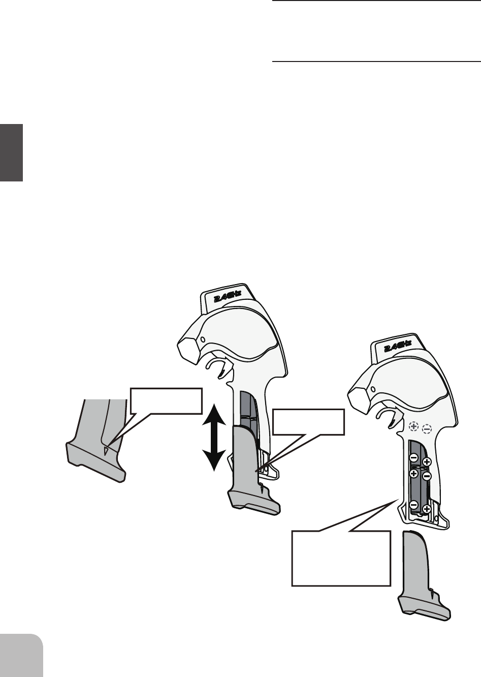
Battery Replacement Method
(4 AA size batteries)
1 Removethebatterycoverfrom
the transmitter by sliding it to the
directionofthearrowinthegure.
2 Removetheusedbatteries.
3 PreparethenewAAsizebatteries.
Payverycloseattentiontothe
polaritymarkingsandinsert
accordingly.
4 Slide the battery cover back onto
thecase.
CAUTION
Alwaysbesureyoureinsertthe
batteriesinthecorrectpolarityorder.
Ifthebatteriesareloadedincorrectly,the
transmittermaybedamaged.
When the transmitter will not be used
foranyshortorlongperiodoftime,
alwaysremovethebatteries.
Ifthebatteriesdohappentoleak,clean
thebatterycaseandcontactsthorough-
ly.Makesurethecontactsarefreeof
corrosion.
Check:
Turn the power switch of the transmitter to
theONposition.Checkthebatteryvoltage
displayontheLEDlight.
If the voltage is low, check the batteries
for insufficient contact in the case or
incorrect battery polarity.
Push
Slide
The battery of
4 AA sizes
are put in.
11
Before Operation
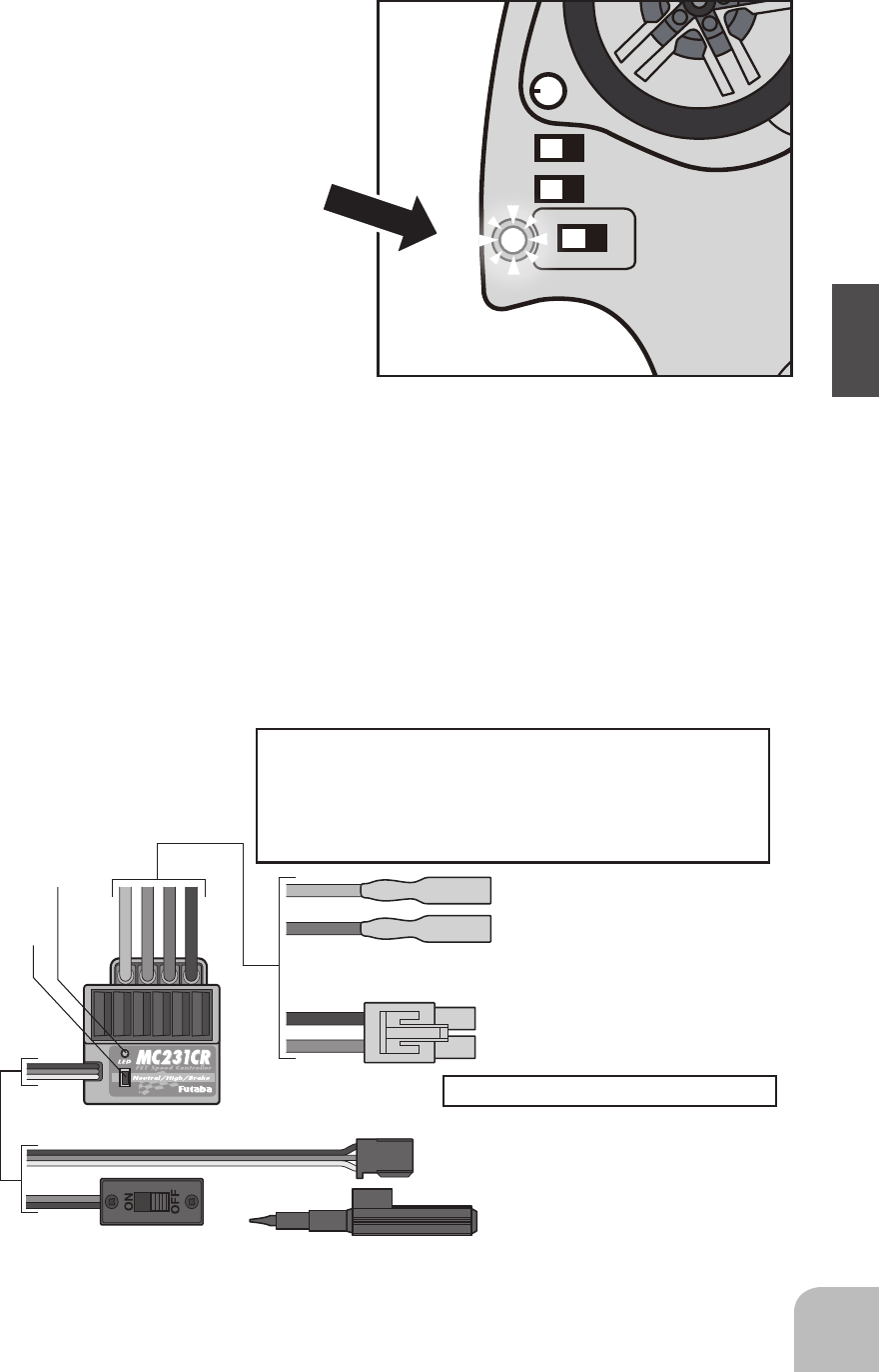
E.S.C. MC231CR / MC331CR
Motor connector
Connects to the motor.
(Orange) is positive. (Blue) is negative.
If the motor rotates in the wrong
direction, interchange the connections of
this connector.
Ni-cd/Ni-MH battery connector
Connects to the running Ni-cd/Ni-MH battery.
(Red) is positive. (Black) is negative.
Receiver connector
Connects to the receiver throttle channel.
Miniature screwdriver
Accessory. Use to press the
pushbutton switch.
Checker LED
Power switch
Pushbutton
switch
MC231CR/MC331CR
(Orange)
(Blue)
(Black)
(Red)
Applicable motors (Number of turns is criteria.)
•Use the MC231CR with a motor with 20T or more turns.
•Use the MC331CR with a motor with 13T or more turns.
*If a motor with a number of turns smaller than the above is used, the heat
protector and overcurrent protection circuit may operate. The number of turns
of the motor is only one criteria. Depending on the running conditions, the
protection circuit may operate even if the condition above is satisfied.
Ni-cd/Ni-MH battery 6~7 cells (7.2~8.4V)
TH.
ON
REV.
ST.
NOR.
ST. D/R
The low battery alarm is meant to be a
safetyfeatureonly.DoNOToperateyour
radio below low battery. Always shut
your radio off as soon as possible after the
low battery warning tone to avoid loss of
control.
Low Battery :
WhentheLEDstarts
blinking, change the batteries
immediately.
12 Assembly / Adjustment
Assembly / Adjustment
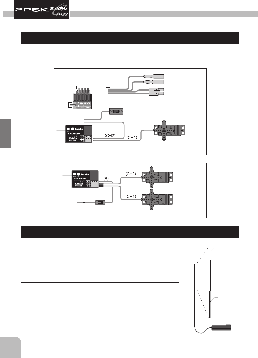
Receiver and Servo Connection
As you connect the receiver, servos and other components, do so in accordance with the
"Assembly Precautions".
Connections when a E.S.C. MC231CR or MC331CR are used.
Steering Servo
Throttle Servo
Receiver
Receiver
Power Switch
To Receiver
Battery
Steering Servo
E.S.C.
Power Switch
Connects to Motor
Connects to Battery
Gas Powered Model
Receiver Antenna Installation
InstalltheR202GFreceiveronthecarasfollows:
Note: The operating range may become shorter, depending on where the
receiver and the antenna are mounted.
WARNING
Installtheantennainthehigherplaceasshowninthegure.
Keepthe antenna as farawayfrom the motor,ESC and other
noisesourcesaspossible.
Puttheantennaintheantennatubetoprotectit.
Donotcuttheantenna.
Donotbendthecoaxialcable.Doingsocausesdamage.
Antenna
tube
Antenna
Coaxial
cable
R202GF

13
Assembly / Adjustment
Assembly Precautions
WARNING
Checkthereceiver,servos,andbatteryconnectors,tobesuretheyarermlyconnected.
Ifaconnectorisnotfullyinserted,vibrationmaycausetheconnectortoworkloosewhile
themodelisoperating.Thiswillresultinlossofcontrol.
Operateeachservohornoveritsfullstrokeandchecktoseethatthelinkagedoesnotbind
orisnottooloose.
Excessiveforceappliedtotheservohornbybindingorpoorinstallationmayleadtoservo
problemsandresultinlossofcontrol.
(Electric Cars and Boats)
Isolatethereceiverfromvibrationbyattachingtothechassisormountingplatewiththick
doublesidedtape.
(Gas Powered Cars and Boats)
Isolatethereceiverfromvibrationbywrappingitinfoamrubberorsimilartypecushioning
material.Protecttheunitfromwaterdamagebyplacingitinaplasticbagorwaterproofra-
diobox.
Thereceivercontainsprecisionelectronicparts.Thesepartsarevulnerabletovibrationand
shock.Anycontactwithmoisture(waterorcondensation)maycausereceivermalfunction
andlossofcontrol.
UUsetheservohornscrew.
Whentheservohorncomesoff,itbecomeslossofcontrol.
Keep all devices that emit high frequency noise, such as motors, batteries, and wiring
thathandlesheavycurrentloads,atleast1/2inchawayfromthereceiverandthereceiver
antenna.
High frequency noise will cause a decrease in operating range and could cause loss of
control.
Installelectronicspeedcontrolheatsinksaswellasothercomponentsthatconduct
electricitysotheycannotcomeincontactwithaluminum,carbonberorothermaterials
thatconductelectricity.
If,forexample,thespeedcontrolcameloosewhilethemodelwasrunningandtouchedan
aluminumchassis,ashortcircuitmayoccur that wouldcause irreparabledamage tothe
systemaswellaslossofcontrol.
Noisesuppressioncapacitorsshouldbeinstalledonalmostallmotors.
Ifthepropercapacitorsarenotinstalled,highfrequencynoisewillreducerangeandcause
lossofcontrolalongwithvariousotherproblems.
Inspectalllinkageinstallationsandanypointwheremetalcouldcomeincontactwithother
metalparts.Makesurethesepartsdonottouchothermetalpartsundervibration.
Shouldalinkageorothermetalpartscomeincontactwithothermetalpartsundervibra-
tion,thehigh frequency noisegeneratedbythis contact willcauseinterferenceand pos-
siblelossofcontrol.
CAUTION
DoNotdisassembleanypartofthissystemthatisnotspeciedintheinstructionmanual.
Futabawillnotberesponsibleforanydamageduetoimproperdisassemblyofanypartof
theradiocontrolsystem.
14 Assembly / Adjustment
How to link the transmitter and the receiver
Eachtransmitterhasanindividuallyassigned,uniqueIDcode.Inordertostartoperation,
the receiver must be linked with the ID code of the transmitter with which it is being
paired.Oncethelinkismade,theIDcodeisstoredinthereceiverandnofurtherlinking
isnecessaryunlessthereceiverneedstobeusedwithanothertransmitter.(ForT/Rset,
thelinkisalreadydoneatfactory.)
Link procedure
1Bring the transmitter and the receiver close
toeachother,withinonemeter.
2Turnonthetransmitterandthereceiver.
3PushandholdtheLinkSwitchofthe
receiver.
4When the link is complete, the LED in the
receiverchangestosolidgreen.
*PleasereferthetablebelowforLEDstatusvsreceiver'scondition.
LED status vs receiver's condition:
Nosignalreception OFF
Receivingsignals On
Receivingsignals,butIDisunmatched. Blink
Receivingsignals,whenF/Sisset. It is turns on and a fast blink for the first one
second.
Fail Safe Function (F/S)
Foranelectriccar(E.C.Suse),
link the transmitter and the
receiver at neutral position.
For the engine car,
link the transmitter and the
receiver at braking position.
This function moves the throttle
servo to a preset position when the
receiver cannot receive the signal
from the transmitter for some
reason.
Whenthesignalfromthe
transmitter can be received again,
this function automatically resets.
The throttle position at the link
operation is memorized.
Link SwitchLED
15
Assembly / Adjustment
Transmitter Set-Up Procedures
*Whenmakingthesesettingsadjustments,dosowiththemotordisconnectedor
the engine not running.
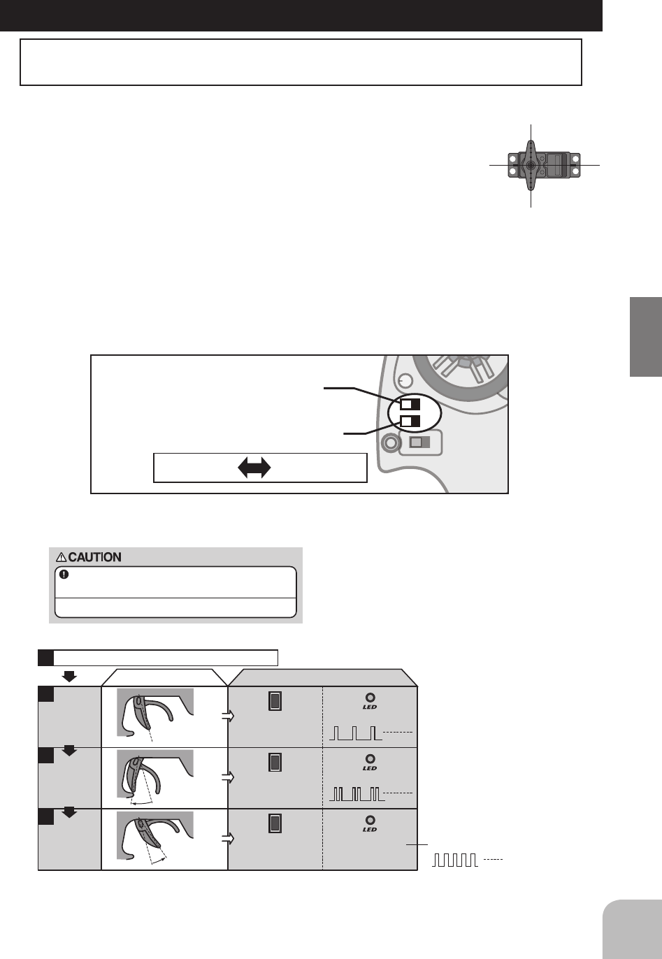
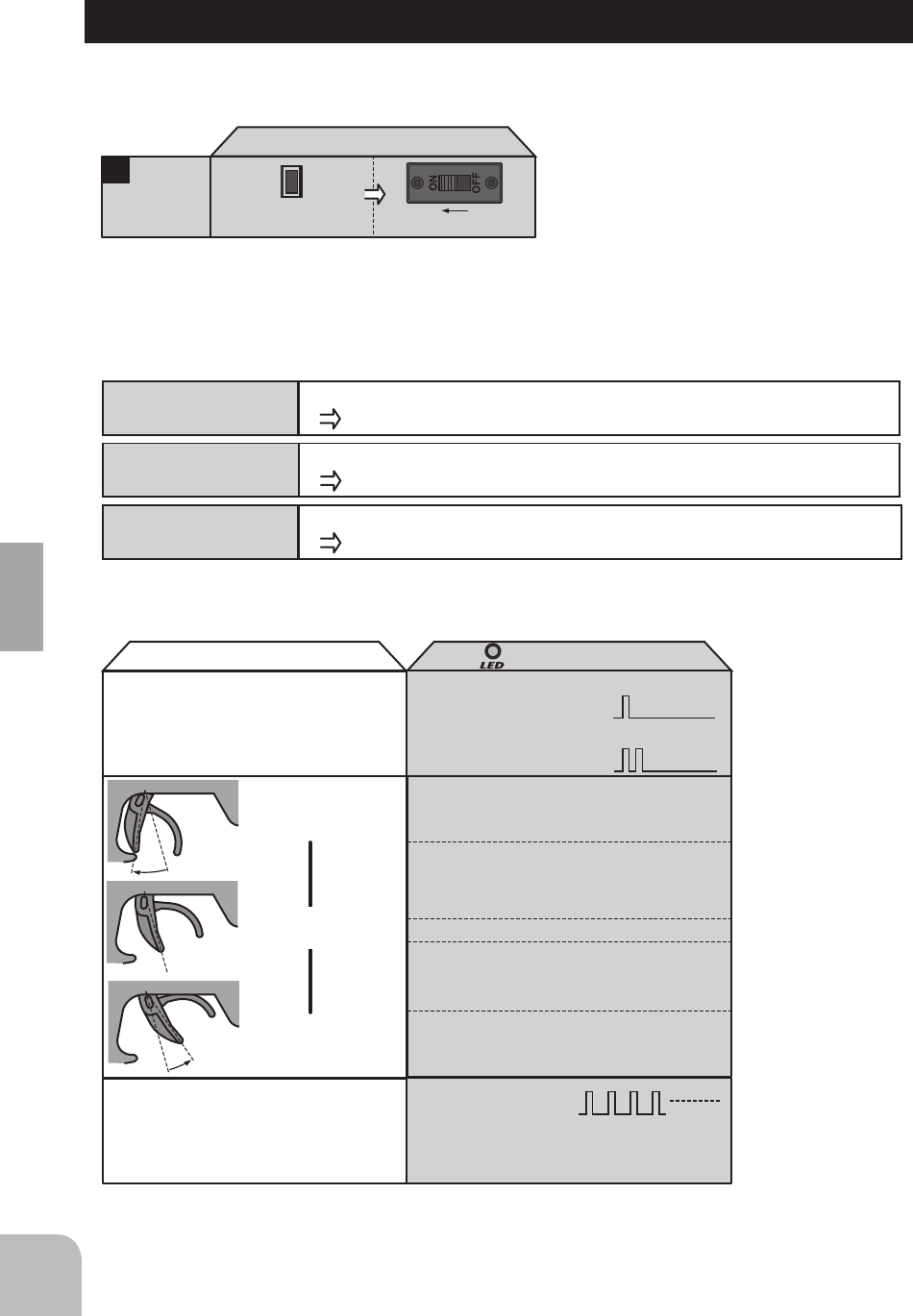
NEUTRAL, HIGH, AND BRAKE MAX POINT SETTINGS
Before setting each point, set the transmitter throttle channel trim to neutral.
Turn on the power in transmitter -> amp order.
1
2
Transmitter throttle operation
・Neutral state ・Press the pushbutton switch.
(0.5 secs or longer)
(Confirmation beep sounds)
・Continuous single blink
MC231CR /MC331CR
(Pushbutton switch operation) (Checker LED)
N
N
Full High
Full brake
N
Neutral point
setting
3
・Full high state ・Press the pushbutton switch.
(Confirmation beep sounds)
・Continuous double blink
・Continuous rapid blink
High point
setting
4
・Full brake state ・Press the pushbutton switch.
(Confirmation beep sounds.)
・If the LED goes out,
setting is complete.
Brake MAX
point setting
* Since the data is read at the end of setting of all points, the points cannot be set independently.
* If the amp power was turned off during setting, the setting points cannot be memorized. (The previous settings are retained.)
* The confirmation beep sounds only when the motor was connected.
If the LED does not go off
but blinks rapidly, setting
was not performed
normally. Repeat setting
from "Neutral point
setting".
Set the steering angle adjustment function (ATV) to
100% and the ABS function and acceleration function
to OFF using the transmitter throttle channel function.
If the steering angle is too large or the ABS and acceleration
functions are on, erroneous operation may occur.
*When using the ABS function, after setting up
the MC231CR / MC331CR, stop the reverse
function, then turn on the ABS function. If the
ABS function is on, the MC231CR / MC331CR
cannot be set up correctly.
Servo Horn Installation Instructions
1 Connect the receiver, servos, and other components and
thenturnonthepowerswitchestotransmitterandreceiver.
*Both servos will move to the neutral position.
2 Atthistimeinstalltheservohorninthemannerdescribedin
theinstructionmanualprovidedwiththemodelthissystem
willbeusedin.
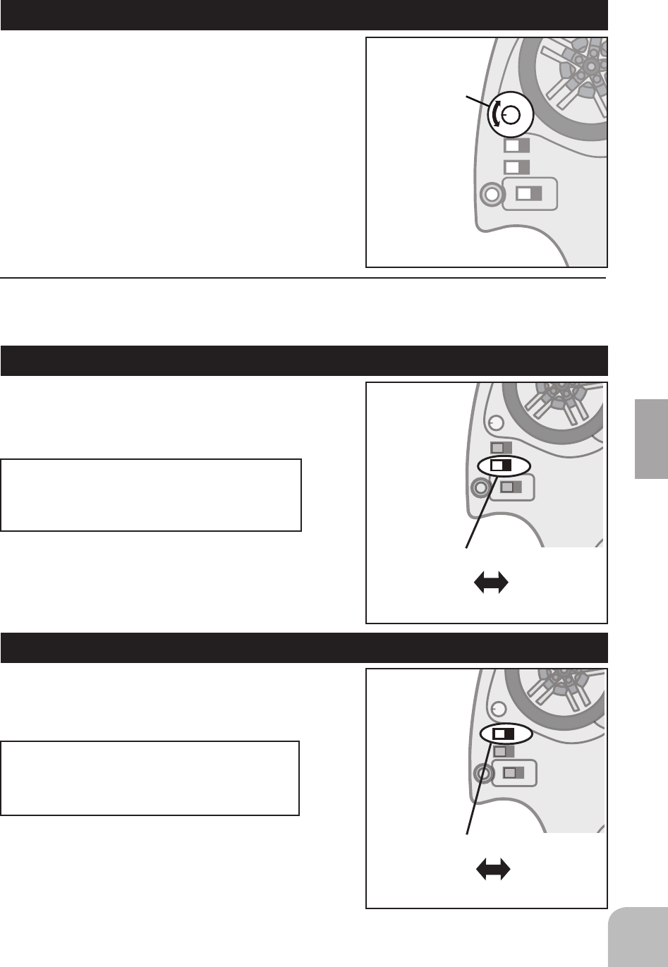
Reversing The Servo Operation Direction
Shouldtheservooperateintheopposite
directionrequiredfor yourapplication,reverse
thedirectionwiththeservoreversing.
E.S.C. MC231CR / MC331CR
TH.
ON
REV.
ST.
NOR.
ST. D/R
Throttle Servo Reversing
Steering Servo Reversing
TH.
REV.
ST.
NOR.
Nor: Normal Rev: Reverse
16 2PSK Functions
2PSK-2.4G Functions
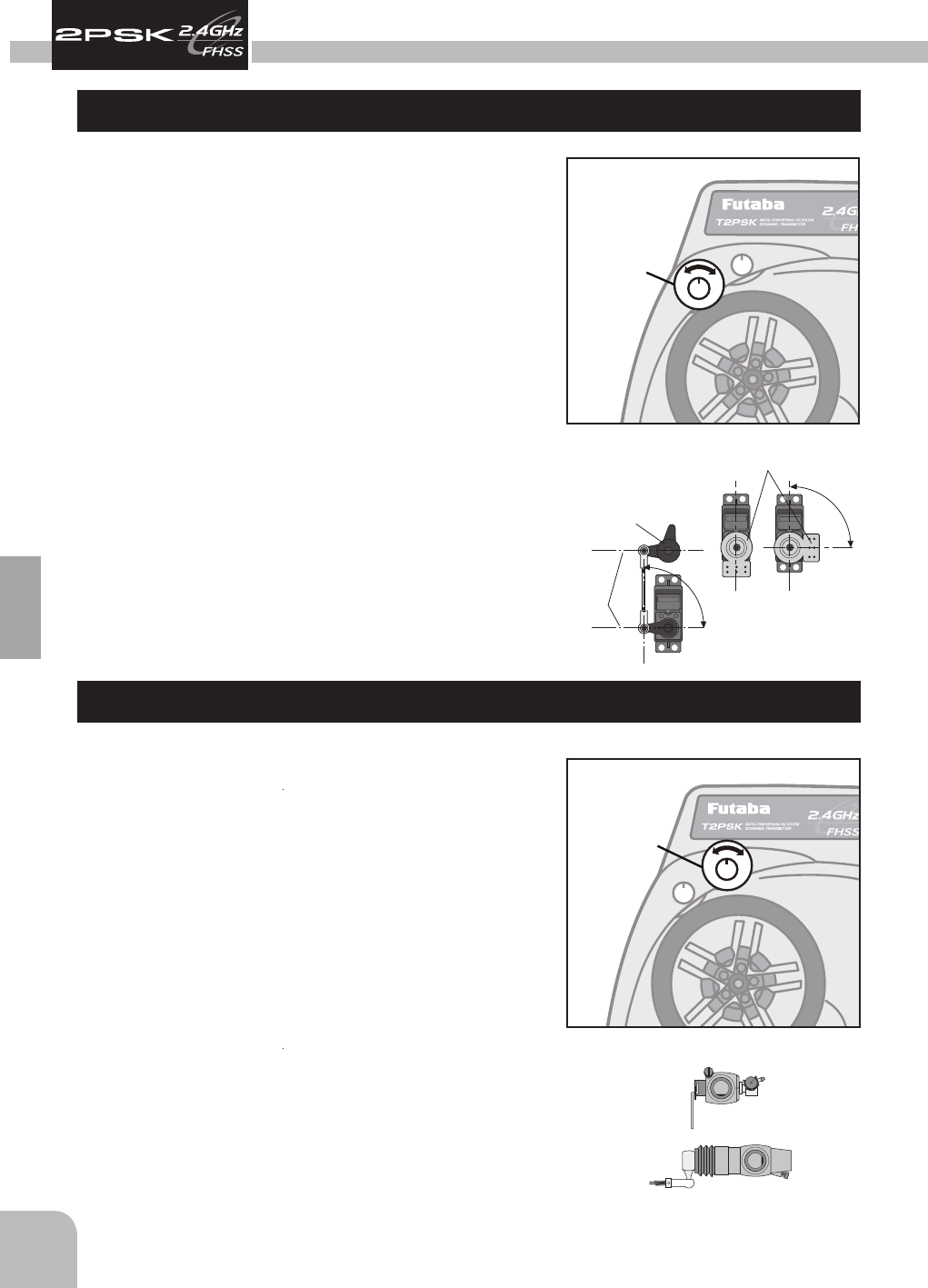
Steering Trim
Throttle neutral adjustments can be made
moving the throttle trim to the left or right.
Racers Tip
Whenusinganelectronicspeedcontrol,setthethrottle
trim to neutral and make adjustments to the speed
control. On a gas powered model, set the trim to
neutral and adjust the linkage to the point where the
carburetor is fully closed in accordance with the engine
instruction manual.
Trim Operation and Travel
Trim adjustments will affect the overall servo travel.
Checkthebrakeside(backward)movementwhen
changes are made.
When trim movement is extreme
If you use most of the trim movement to get the servo
to the neutral position , recenter the servo horn closer
to the neutral position and inspect your throttle linkage.
Throttle Trim
Steering neutral adjustments can be made by
moving the Steering trim knob to the left or right.
Racers Tip
When you install a servo, always check to be sure the
servo is at its neutral position. Adjust the servo horn
hole position and linkage so both are parallel.When a
servo saver is used, place it as close to center position as
possible. Be sure the steering trim on the transmitter is at
the neutral position.
Trim Operation And Maximum Travel
Changingthetrim can affecttheoverall settings.When
adjustments are made with the trims, recheck your
installationformaximumtravel.(SteeringD/R).
When Trim usage is extreme
If it takes most of your trim movement to get a servo
to the neutral position, reposition the servo horn or
servo saver on the servo and inspect your linkage
installation.
(Drum Type)
(Slide Type)
Carburetor Fully Closed
90°
90°
Parallel
Servo Saver
Direct Servo Saver Horn
Steering Trim
ST.
TH.
TRIM
ST. D/R
ST.
TH.
REV.
NOR.
ST.
TH.
TRIM
ST. D/R
TH.
Throttle Trim
17
2PSK Functions
Usethisfunctiontoadjustthesteeringtravelof
your model. If the model understeers (push) while
cornering,addsteeringbyturningC,WoftheD/
R button.When the model oversteers (loose), take
awaysteeringbyturningC,C,WoftheD/Rbutton.
This function reverses the
rotation direction of the
Steering servo.
Whenthetrimpositiondeviatesfrom
the center, the deviation will be on the
opposite side when the servo is reversed.
Throttle Servo Reversing (REV-CH2)
This function reverses the rotation direction
of the throttle servo.
Whenthetrimpositiondeviatesfrom
the center, the deviation will be on the
opposite side when the servo is reversed.
WARNING
Besurethat thesteering linkagedoesnot bind orcomein contact withany suspension
parts orarms. If unreasonableforceis applied tothe servo, the servomaybe damaged
andresultinlossofcontrol.
Steering Dual Rates
Steering Servo Reversing
Throttle Servo Reversing
TH.
ON
REV.
ST.
NOR.
ST. D/R
Steering Dual Rates
ST. D/R
TH.
ON
REV.
ST.
NOR.
ST. D/R
Steering Servo Reversing
Nor: Normal Rev: Reverse
ST.
TH.
ON
REV.
ST.
NOR.
ST. D/R
Nor: Normal Rev: Reverse
TH.
Throttle Servo Reversing
18 2PSK Functions
MC231CR/MC331CR
BRAKE/REVERSE OPERATING INSTRUCTIONS
Operation can be switched to reverse operation by returning the throttle trigger (or throttle stick) from the brake
position to the neutral position.
CANCELLING THE REVERSE FUNCTION
The amp reverse function can be cancelled by the following method so that the model can be used even in races
that prohibit reverse running. (Brake operation only)
While pressing
the pushbutton switch, set the power switch to ON.
ON
MC231CR / MC331CR
(Pushbutton switch operation) (Power switch)
1
Reverse
function
cancellation
* When desired, you can enable the cancelled reverse
function by repeating the operation shown at the left.
(The reverse function is switched alternately.)
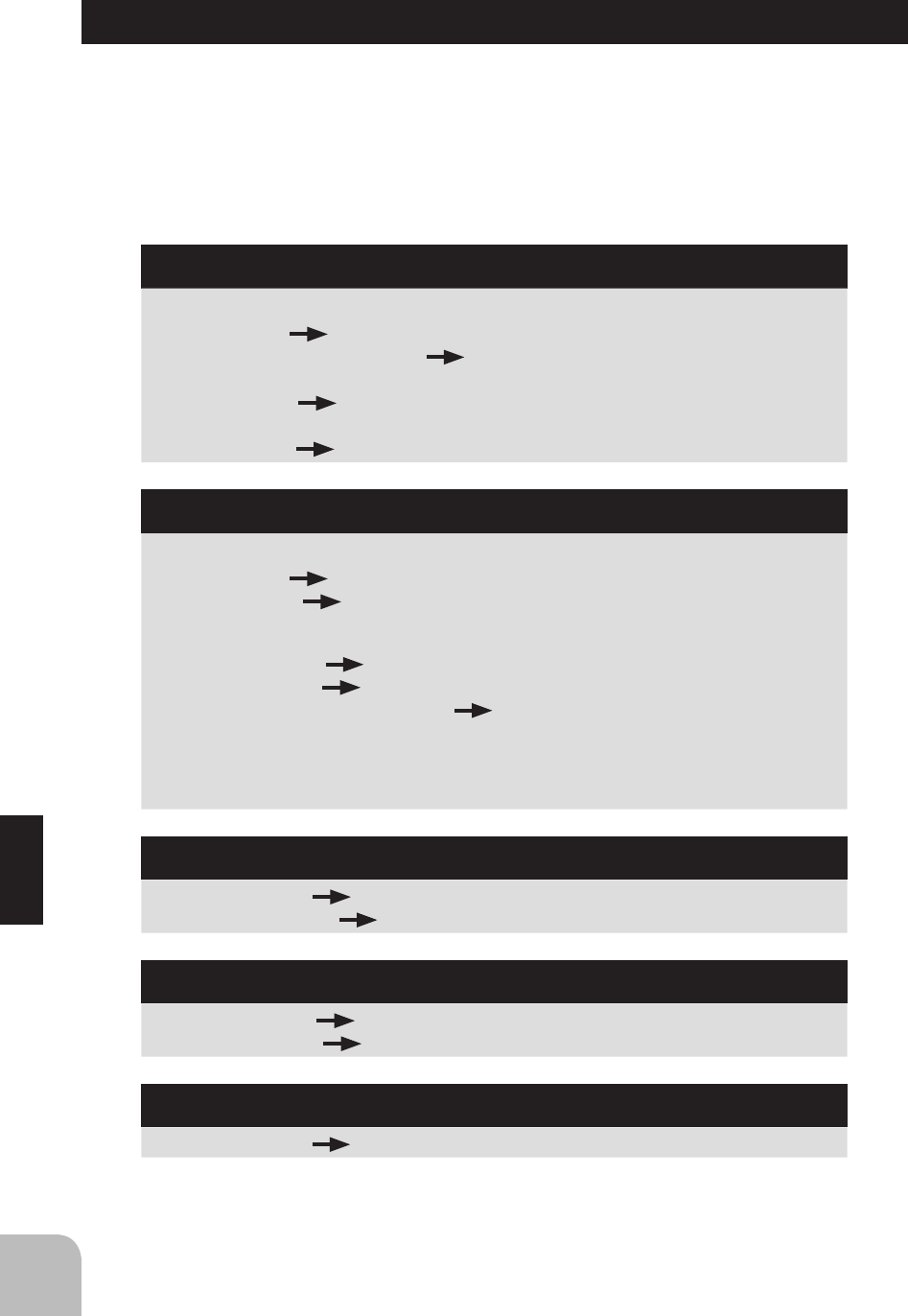
CHECKER LED DISPLAY
The amp operates linearly in proportion to the amount of forward, reverse, and brake operation. The amp operating
state can be checked with the checker LED as shown below.
PROTECTION CIRCUIT OPERATION
The following protection circuits are built into the MC231CR / MC331CR. When a protection circuit operates,
remove the cause before operating the model again.
Operation
Amp power ON
Checker LED display
(Reverse operation set)
Single blink
(Single confirmation beep)
(Only brake operation set)
Off
On
On
Off
Off
Double blink
(Two confirmation beeps)
Blinks. (Confirmation
beep also sounds.)
* Confirmation beep only sounds when the motor was connected.
High point
Neutral point
Brake MAX point
*Becomes brighter nearer the high
point.
*Becomes brighter nearer the
brake MAX point.
*Not used with PCM receivers.
*When the transmitter is OFF, this function is
not performed in environments such that the
servo operates erroneously.
When an overcurrent flows due to an output short circuit, etc., the overcurrent protection circuit automatically
limits the current to protect the FET.
Remove the cause of the short circuit, etc. before operating the model again.
(Amp power left on alarm)
When the transmitter power
was turned off first.
Forward
Reverse
/brake
Overcurrent
protection
When abnormal heating of the FET due to an overload, etc. is detected, the heat protector operates so that
the speed is gradually reduced.
When the FET temperature drops, the heat protector automatically resets. However, remove the cause
of the overheating before operating the model again.
Heat protector
When the Nicd battery voltage drops, this function limits the motor output current and ensures steering operation.
After the speed drops, immediately recover the vehicle.
Low voltage
operation

19
2PSK Functions
Reference
Ratings
Communication method:
One-way operation system
Maximum operating range:
200m(Optimumcondition)
For safety:
F/S (Throttle), ID (About 4 billion ways of pair
identications)
Transmitter T2PSK
(FHSSsystem,wheeltype,2channels)
Transmitting frequency:
2.4GHz band
Power requirement:
(Drycellbattery)Penlightx4(6V)
Current drain:
100mA
Transmission antenna:
1/2λdi-pole(Built-in)
Receiver R202GF:
(FHSS/S-FHSSsystem,2channels)
Power requirement:
4.8V~ 7.4VRechargeablebattery
Size:
23x35x9mm(excludingaprojectionpart)
Weight:
6g
Servo S3003
(Standardservo)
Power requirement:
6V(commonwithreceiver)
Current drain:
8mA(at6V/Idle)
Output torque:
4.1kg-cm(57in.-oz.)at6V
Operating speed:
0.19sec/60degreeat6V
Size:
40.4x19.8x36mm(1.59x0.78x1.42in.)
Weight:
37.2g(1.31oz.)
Servo S3050
(Standarddigitalservo)
Power requirement:
6V(commonwithreceiver)
Current drain:
8mA(at6V/Idle)
Output torque:
6.5kg-cm(90.3oz.-in.)at6V
Operating speed:
0.16sec/60degreeat6V
Size:
40.0x20.0x38.1mm(1.57x0.79x1.50in.)
Weight:
49g(1.72oz.)
E.S.C. MC231CR / MC331CR
(Electronicspeedcontrol)
Operating system:
Forward, reverse, and brake operations are all
linear.
Power requirement:
Ni-cd/Ni-MHbattery6-7cells(7.2to8.4V)
PWM frequency:
1.5kHz(xed)
Setting:
One-touch input by pushbutton switch. Set data is
saved to built-in EEPROM.
Current capacity (FET rating):
Forward=90A/200A,reverse=45A/100A
Size:
27.1x33.3x12.8mm(1.07x1.31x0.50in.)
(excludingprotrudingparts)
Silicon cord gauge size:
AWG16/AWG14equivalent
Weight:
44/45g(1.55/1.59oz.)
(includingconnectorsandswitches)
BEC voltage:
6.0V
*Specicationsandratingsaresubjecttochangewithoutpriornotice.
NOTE:FutabaFHSSsystem,T2PSKtransmitterandR202GFreceiver,doesnotworkwithcur-
rent Futaba FASST system. Please useT2PSK and R202GF in pairs. Futaba FASST system
andFHSSsystemarenotcompatibleeachother.
20 Reference
If your system fails to operate or you experience a short range problem or erratic control,
check the table below for possible causes. If after you have followed the suggestions
listed the problem is not corrected, return the system to our service department for
inspection and repair.
(Item Check)
Troubleshooting
Transmitter
Battery
Deadbattery Changethebatteries.
Batteriesinsertedincorrectly. Reloadthebatteriesinaccordancewiththe
polaritymarkings
Faultycontact Checktoseeifthecontactsarebentandnotmakinggood
contact
Dirtycontacts Cleanthecontactsandcheckforcorrosion.
Receiver
Battery
Deadbattery Replaceorrecharge
Wrongpolarity Checkconnections
Antenna
Nearotherwiring Moveawayfromwiring
Wasantennacut Requestrepair
Istheantennainstalledcorrectly Refertothereceiverinstallation.
Monitor LED
ChecktheLEDofthereceiver.
Refertothe"Howtolinkthetransmitterandthereceiver".
Connector connections
Wiringincorrect Insertallconnectorsrmly
Looseconnections Pushtheconnectorinrmly
Linkage
Bindingorloose Adjustthelinkageinmodel
Ismovementstiff Adjustlinkageinmodel
Motor (Electric powered)
Noiseproblems Installcapacitorsonmotor

21
Reference
Low Battery
WhentheLEDstartsblinking,replacethebatteriesimmediately.
LED light:
TH.
ON
REV.
ST.
NOR.
ST. D/R
Error Displays
WARNING
Whenalowbatteryalarmisgenerated,ceaseoperation
immediately and retrieve the model. If the battery goes dead
whileinoperation,youwilllosecontrol.
Beforerequestingrepair,readthisinstructionagainandrecheckyoursystem.Shouldthe
problemscontinue,requestasfollows.
(Information needed for repair)
Describe the problem in as much detail as possible and send the letter along with the
systeminquestion.
•Symptom(Includingtheconditionsandwhentheproblemoccurred)
•R/CSystem(Sendtransmitter,receiverandservos)
•Model(Typeofmodel,brandnameandmodelnumberorkitname)
•Detailedpackinglist(Makealistofallitemssentinforrepair)
•Yourname,addressandtelephonenumber.
(Warranty)
ReadtheWarrantycard.
•Whenrequestingwarrantyservice,sendthecardorsometypeofdatedproofof
purchase.
Hobby Services (U.S. only)
3002N.ApolloDrive,Suite1
Champaign,IL61822U.S.A.
Phone:(217)398-0007
www.hobbyservices.com
FUTABACORPORATIONPhone:+81475326982,Facsimile:+81475326983
1080Yabutsuka,Chosei-mura,Chosei-gun,Chiba-ken,299-4395,Japan
©FUTABACORPORATION2012,10(1)
When requesting repair
Error Displays