Futaba T3GR-24G Radio Control Transmitter User Manual 3GR 2 4G 01 ENG
Futaba Corporation Radio Control Transmitter 3GR 2 4G 01 ENG
Futaba >
Manual
3GR-2.4G
3-channel, FASST
Radio control system for Car
1M23N18005
Thank you for purchasing a Futaba 3GR-2.4GHz system.
Before using your 3GR-2.4GHz system, read this manual carefully in order to use your R/C set safely.
After reading this manual, store it in a safe place.
Application, Export, and Modification
1. This product may be used for models only. It is not intended for use in any application other than the
control of models for hobby and recreational purposes.
2. Exportation precautions:
(a) When this product is exported from the country of manufacture, its use is to be approved by the laws govern-
ing the country of destination for devices that emit radio frequencies. If this product is then re-exported to other
countries, it may be subject to restrictions on such export. Prior approval of the appropriate goverment authori-
ties may be required. If you have purchased this product from an exporter outside your country, and not the
authorized Futaba distributor in your country, please contact the seller immediately to determine if such export
regulations have been met.
(b) Use of this product with other than models may be restricted by Export and Trade Control Regulations, and
an application for export approval must be submitted.
3. Modification, adjustment, and replacement of parts: Futaba is not responsible for unauthorized
modification, adjustment, and replacement of parts on this product. Any such changes may void the
warranty.
Compliance Information Statement (for U.S.A.)
This device, trade name Futaba Corporation of America, model number R603FF, complies with part
15 of the FCC Rules. Operation is subject to the following two conditions:
(1) This device may not cause harmful interference, and
(2) This device must accept any interference received, including interference that may cause undesired
operation.
The responsible party of this device compliance is:
Futaba Service Center
3002 N Apollo Drive Suite 1, Champaign, IL 61822 U.S.A.
TEL (217)398-8970 or E-mail: support@futaba-rc.com (Support)
TEL (217)398-0007 or E-mail: service@futaba-rc.com (Service)
Battery Recycling (for U.S.A.)
The RBRCTM SEAL on the (easily removable) nickel-cadmium battery contained in
Futaba products indicates that Futaba Corporation of America is voluntarily participating
in an industry program to collect and recycle these batteries at the end of their useful
lives, when taken out of service within the United States. The RBRCTM program provides
a convenient alternative to placing used nickel-cadmium batteries into the trash or mu-
nicipal waste system, which is illegal in some areas.
You may contact your local recycling center for information on where to return the spent battery.
Please call 1-800-8-BATTERY for information on Ni-Cd battery recycling in your area. Futaba Cor-
poration of America's involvement in this program is part of its commitment to protecting our environ-
ment and conserving natural resources.
RBRCTM is a trademark of the Rechargeable Battery Recycling Corporation.
Warning: This product contains a chemical known to cause cancer and birth defects (or other
reproductive harm).

•No part of this manual may be reproduced in any form without prior permission.
•The contents of this manual are subject to change without prior notice.
•This manual has been carefully written. Please write to Futaba if you feel that any corrections or clarifications
should be made.
•Futaba is not responsible for the use of this product.
4
For Your Safety As Well As That Of Others...........6
Explanation of Symbols ................................................................................ 6
2.4GHz System Precautions ......................................................................... 6
Operation Precautions .................................................................................. 7
NiCd Battery Handling Precautions ............................................................. 9
Storage and Disposal Precautions ............................................................ 10
Other Precautions ....................................................................................... 11
Table Of Contents
Before Using ...........................................................12
Features........................................................................................................ 12
Set Contents ................................................................................................ 14
Nomenclature (Transmitter/Receiver/Servo) ............................................ 15
Installation ..............................................................21
Receiver and Servo Connections .............................................................. 21
Installation Safety Precautions .................................................................. 21
Initial Set-Up ...........................................................23
How to link the transmitter and the receiver............................................. 23
Preparations (Transmitter) ......................................................................... 24
Functions ................................................................30
End Point Adjuster ...................................................................................... 30
Steering Speed ............................................................................................ 33
Steering EXP / Throttle EXP ....................................................................... 34
A.B.S. Function ............................................................................................ 36
Throttle Acceleration................................................................................... 38
Brake Mixing ................................................................................................ 40
Programmable Mixing ................................................................................. 41
Fail Safe/Battery Fail Safe (HRS System Only) ......................................... 42
Trim ............................................................................................................... 43
Steering D/R ................................................................................................. 44
ATL Function ............................................................................................... 44
Channel 3 Position ...................................................................................... 45
Subtrim ......................................................................................................... 46
Servo Reverse.............................................................................................. 47
Function Map ..........................................................28
(Function Selection) .................................................................................... 28
5
Model Select ...................................................................................... 48
Timer................................................................................................... 49
(System Functions)
Model Copy ........................................................................................ 51
Model Reset ....................................................................................... 52
Model Name ....................................................................................... 52
HRS/PPM Select ................................................................................ 53
Function Select Switch ..................................................................... 54
Function Select Lever ....................................................................... 55
Condition 2 Selection........................................................................ 56
LED Mode Selection .......................................................................... 56
Throttle Neutral Adjuster .................................................................. 57
For Your Safety
As Well As
That Of Others
Before
Using
Installation
Initial
Set-Up
Function
Map
Functions
Reference
Reference .........................................................58
Ratings ............................................................................................... 58
Optional Parts .................................................................................... 59
Troubleshooting ................................................................................ 60
Error Displays .................................................................................... 61
When requesting repair .................................................................... 62
6
For Your Safety As Well As That Of Others
For Your Safety As Well As That Of Others
Use this product in a safe manner. Please observe the following safety precautions at
all times.
Explanation of Symbols
The parts of this manual indicated by the following symbols are extremely important
and must be observed.
Danger
Indicates a procedure which could lead to a dangerous situ-
ation and may cause death or serious injury if ignored and
not performed properly.
Warning Indicates procedures which may lead to dangerous situa-
tions and could cause death or serious injury as well as su-
perficial injury and physical damage.
Caution Indicates procedures that may not cause serious injury, but
could lead to physical damage.
Symbols: ; Prohibited ; Mandatory
Symbols Explanation
Special attention should be paid before turning on the system while other cars are run-
ning or other airplanes are flying because the 2.4GHz RC system could potentially af-
fect them.
Warning
2.4GHz System Precautions
Prohibited Procedures
Always use R603FF under the following conditions;
Power supply: 6V Nicd battery (PPM/HRS mode)
Servo: 6V type Futaba Digital Servo (HRS mode)
If these conditions are not followed, control may be impossible or the servo may be damaged.
Caution
Mandatory Procedures
7
For Your Safety As Well As That Of Others
Operation Precautions
Warning
Prohibited Procedures
Do not operate outdoors on rainy
days , run through puddles of water,
or use when visibility is limited.
Should any type of moisture (water or snow) enter any
component of the system, erratic operation and loss
of control may occur.
Do not operate in the following
places.
-Near people or roads.
-On any pond when boats are present.
-Near high tension power lines or communi-
cation broadcasting antennas.
Interference could cause loss of control. Improper in-
stallation of your Radio Control System in your model
could result in serious injury.
Do not operate this R/C system when
you are tired, not feeling well or under
the influence of alcohol or drugs.
Your judgment is impaired and could result in a dan-
gerous situation that may cause serious injury to your-
self as well as others.
Mandatory Procedures
Adjust the antenna vertically to the ground.
Otherwise, the operating range may become shorter.
Always perform an operating range check prior to use.
Problems with the radio control system as well as improper installation in a model could cause loss of control.
Simple range test method;
Have a friend hold the model, or clamp it down or place it where the wheels or prop cannot come in contact with any
object. Walk away and check to see if the servos follow the movement of the controls on the transmitter. Should you
notice any abnormal operation, do not operate the model. Also check to be sure the model memory matches the
model in use.
Caution
Prohibited Procedures
Do not touch the engine, motor, speed control or
any part of the model that will generate heat while
the model is operating or immediately after its use.
These parts may be very hot and can cause serious burns.
Never hold only the an-
tenna.
Hold the grip handle, otherwise the
antenna may be damaged.
Mandatory Procedures
When making adjustments to the model, do so with the engine not running or the motor
disconnected.
You may unexpectedly lose control and create a dangerous situation.
8
For Your Safety As Well As That Of Others
(Turning on the power switches)
Always check the throttle stick on the transmitter to be sure it is at the neutral position.
1. Turn on the transmitter power switch.
2. Turn on the receiver or speed control power switch.
(Turning off the power switches)
Always be sure the engine is not running or the motor is stopped.
1. Turn off the receiver or speed control power switch.
2. Then turn off the transmitter power switch.
If the power switches are turned off in the opposite order the model may unexpectedly run out of control and cause
a very dangerous situation.
(Fail safe function) ---when using HRS mode
Before running (cruising), check the fail safe function.
Check Method:
Before starting the engine, check the fail safe function as follows:
1. Turn on the transmitter and receiver power switches.
2. Wait at least one minute, then turn off the transmitter power switch. (The transmitter automatically transfers the fail
safe data to the receiver every minute.)
3. Check if the fail safe function moves the servos to the preset position when reception fails.
The fail safe function is a safety feature that minimizes set damage by moving the servos to a preset position when
reception fails. However, if set to a dangerous position, it has the opposite effect.
Setting example: Throttle idle or brake position
9
For Your Safety As Well As That Of Others
NiCd Battery Handling Precautions
(Only when NiCd batteries are used)
Warning
Mandatory Procedures
Always check to be sure your batter-
ies have been charged prior to oper-
ating the model.
Should the battery go dead while the model is operat-
ing, loss of control will occur and create a very dan-
gerous situation.
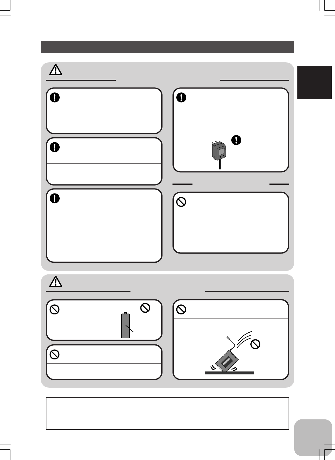
To recharge the transmitter and/or re-
ceiver NiCd batteries, use the special
charger made for this purpose.
Overcharging could cause the NiCd battery to over-
heat, leak or explode. This may lead to fire, burns,
loss of sight and many other types of injuries.
Caution Prohibited Items
Do not use commercial AA
size NiCd batteries.
Quick charging may cause the
battery contacts to overheat and
damage the battery holder.
Do not short circuit the NiCd battery
terminals.
Causing a short circuit across the battery terminals
may result in abnormal heating, fire and burns.
Do not drop the NiCd battery or ex-
pose it to strong shocks or vibrations.
The battery may short circuit and overheat. Electrolyte
may leak out and cause burns or chemical damage.
When the model is not being used,
always remove or disconnect the
NiCd battery.
Leaving the battery connected could create a dangerous
situation if someone accidentally turns on the receiver
power switch. Loss of control would occur.
Special
Charger
Shock
Prohibited
NiCd AA size
batteries.
Use
prohibited
Do not throw NiCd batteries into a
fire. Do not expose NiCd batteries to
extreme heat. Also do not disas-
semble or modify a NiCd battery
pack.
Overheating and breakage will cause the electrolyte
to leak from the cells and cause skin burns, loss of
sight as well as other injuries.
When the system will not be used for
any length of time store the system
with batteries in a discharged state.
Be sure to recharge the batteries prior
to the next time the system is used.
If the batteries are repeatedly recharged in a slightly
discharged state the memory effect of the NiCd bat-
tery may considerably reduce the capacity. A reduc-
tion in operating time will occur even when the batter-
ies are charged for the recommended time.
<NiCd Battery Electrolyte>
The electrolyte in NiCd batteries is a strong alkali. Should you get even the smallest amount of the
electrolyte in your eyes, DO NOT RUB. Wash immediately with water and seek medical attention at
once. The electrolyte can cause blindness. If electrolyte comes in contact with your skin or clothes,
wash with water immediately.
Prohibited Items
10
For Your Safety As Well As That Of Others
Storage and Disposal Precautions
Warning
Prohibited Procedures
Do not leave the radio system or models within the reach of small children.
A small child may accidentally operate the system. This could cause a dangerous situation and injuries. NiCd
batteries can be very dangerous when mishandled and cause chemical damage.
Caution
Prohibited Procedures
Do not store your R/C system in the
following places.
- Where it is extremely hot or cold.
- Where the system will be exposed to direct
sunlight.
- Where the humidity is high.
-Where vibration is prevalent.
-Where dust is prevalent.
-Where the system would be exposed to
steam and condensation.
Storing your R/C system under adverse conditions
could cause deformation and numerous problems
with operations.
Mandatory Procedure
If the system will not be used for a
long period of time, remove the bat-
teries from the transmitter and model
and store in a cool, dry place.
If the batteries are left in the transmitter, electrolyte
may leak and damage the transmitter. This applies to
the model also. Remove the batteries from it also to
prevent damage.
<NiCd Battery Recycling>
A used NiCd battery is valuable resource. Insulate the battery terminals and dispose of the battery by
taking it to a battery recycling center.
11
For Your Safety As Well As That Of Others
Other Precautions
Caution
Prohibited Procedures
Do not expose plastic parts to fuel,
motor spray, waste oil or exhaust.
The fuel, motor spray, waste oil and exhaust will pen-
etrate and damage the plastic.
Always use only genuine Futaba
transmitters, receivers, servos, FET
amps (electronic speed
controls),NiCd batteries and other op-
tional accessories.
Futaba will not be responsible for problems caused by
the use of other than genuine Futaba parts. Use the
parts specified in the instruction manual and catalog.
Mandatory Procedures

12
Before Using
This system is based on the combination of the newly developed 2.4GHz transmitter
and its corresponding receiver. The system utilizes the 2.4GHz-SS radio communica-
tion and an ultra small antenna. In addition, the system inherits Futaba's unique HRS
(High Response System).
- 2.4GHzSS (Spread Spectrum) radio communication system
- Frequency channel setting unnecessary
Sifting the channels within the 2.4GHz band automatically, this system minimizes
the interference from other 2.4GHz systems.
- Accepts no unwanted signals by using ID code
- The function "Auto-Detect" is utilized to automatically determine which mode
is active, HRS or PPM mode. (R603FF)
- Short and small antenna (T3GR-2.4G)
- Simple segment type LCD display and four edit keys for easy data setup
- 10 model memory
Model names can use up to 3 letters, numbers, and symbols so that easily understood
names can be set. Model copy function simplifies creation of a model memory with
different fine setups.
- Two function groups: Frequently used functions / System functions
Frequently used functions can be easily called from the initial screen with Select Key
(SEL).
- Brake mixing for large cars (BMX)
Brake mixing of the front and rear wheels of 1/5GP cars, etc. has balance adjustment
functions.
- Steering dual rate (D/R-ST)
Steering angle can be adjusted with digital trim lever.
- Anti-skid Braking System (ABS)
This function applies the brakes so that the tires of gasoline engine cars, etc. do not
lose their grip on the road even when braking at corners.
- Throttle acceleration (ACC)
Gasoline engine cars have a time lag before the clutch and brakes are connected. The
ACC function minimizes this time lag.
- Steering speed (SPD)
When you sense that the steering servo is too fast, etc., the servo operating speed
(direction that suppresses the maximum speed) can be adjusted.
- Racing timer (TIMER) : Up timer or Down timer can be selected.
A lap time can record 100 lap times and the total time. The timer can also be started
automatically by trigger operation. The race time can be set.
Before Using
Features

13
Before Using
- Digital trim: Steering trim, Throttle trim, Steering D/R
The current position is displayed on the LCD screen for about three seconds when
each digital trim is operated.
- Function select lever function (FNC-DT1/DT2/DT3/DT4)
This function assigns a function to levers (digital trims, grip levers). Trim positioning
at each model call is unnecessary because all the levers are digital.
- Function select switch function (FNC-SW1/SW2)
This function assigns a function to the two installed switches.
- Condition 2 Selection (COND2)
In specific functions, two rates can be set up, and switched with SW1 switch simulta-
neously during a run.
- NEW design considers operability and weight balance
- Stick Lever Head Adjustment
- High luminosity blue LED pilot lamp (LED-MD)
You can select your desired brightness of the pilot lamp. (Four steps)
- Throttle Neutral Adjuster (THR-NT)
You can select your desired throttle neutral position. (7:3 or 5:5)
14
Before Using
Set Contents
Your 3GR-2.4GHz system includes the following:
- If any of the set contents are missing, or you have any questions, please contact the
dealer where the unit was purchased.
Transmitter T3GR-2.4G
Receiver
Miscellaneous
3GR-2.4GHz System
R603FF
Receiver switch
Instruction manual
Always use only genuine Futaba transmitter, receiver, FET amp, NiCd battery and other
optional parts.
Futaba will not be responsible for damage caused by other than genuine Futaba parts and components. Use only
the genuine Futaba parts and components listed in the instruction manual and catalog.
Caution
Always use R603FF under the following conditions:
Power supply: 6V NiCd battery (PPM/HRS mode)
Servo: 6V type Futaba Digital Servo (HRS mode)
If the conditions are different, control is impossible or the servo may be damaged.
Caution
15
Before Using
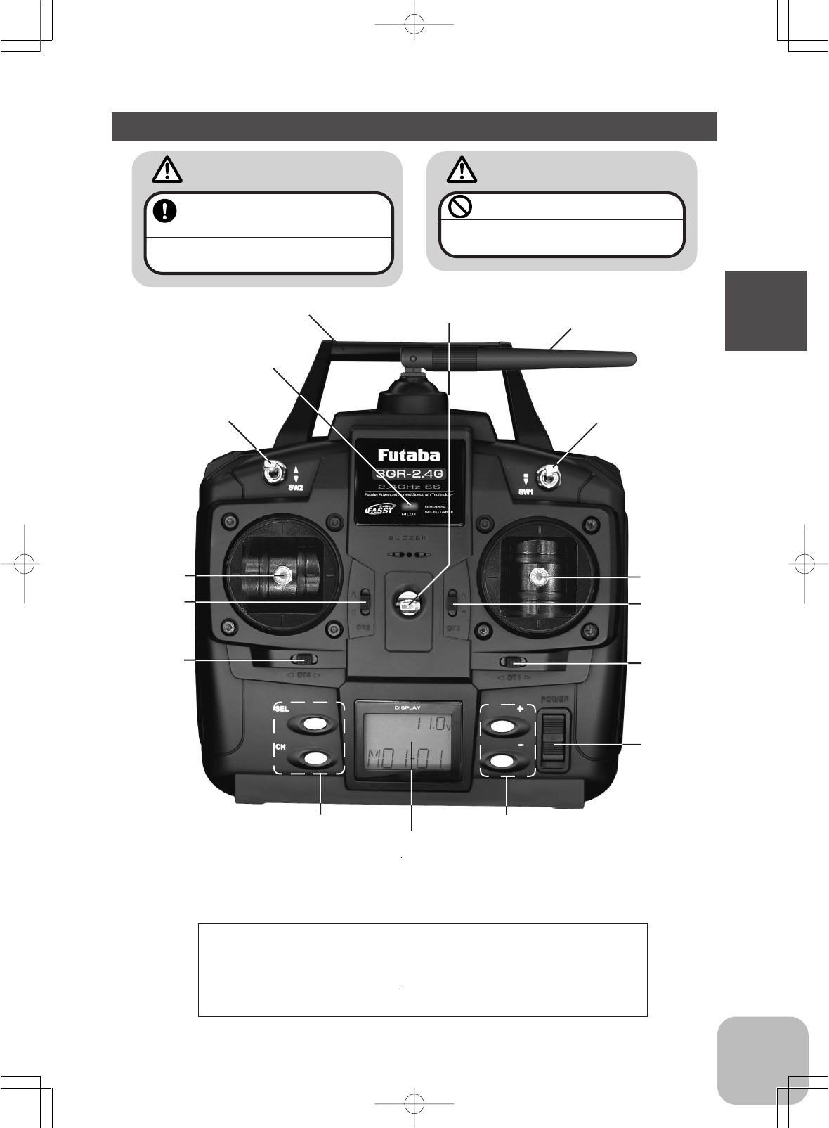
Transmitter T3GR-2.4G
Throttle
trim
(DT2)
Edit keys LCD screen
Pilot lamp
Switch ( SW2)
Steering
dual rate
lever(DT3)
ATL
lever
(DT4)
Antenna
Power
switch
Steering
trim
(DT1)
Steering
stick
Throttle
stick
Switch (SW1)
*The switches and levers in the figure are shown in the initial
setting position.
Precautions when turning the power switch on and off.
When the data is changed using the edit keys or trim levers, wait
at least two seconds before turning off the power. If the power is
turned off within two seconds after the data was changed, the
new data will not be written to memory.
Edit keys
Neck strap hook
Carrying handle
Adjust the antenna vertically to
the ground.
Otherwise, the operating range may become
shorter.
Warning
Never hold the antenna alone.
Hold the carrying handle. Otherwise the an-
tenna may be damaged.
Caution
16
Before Using
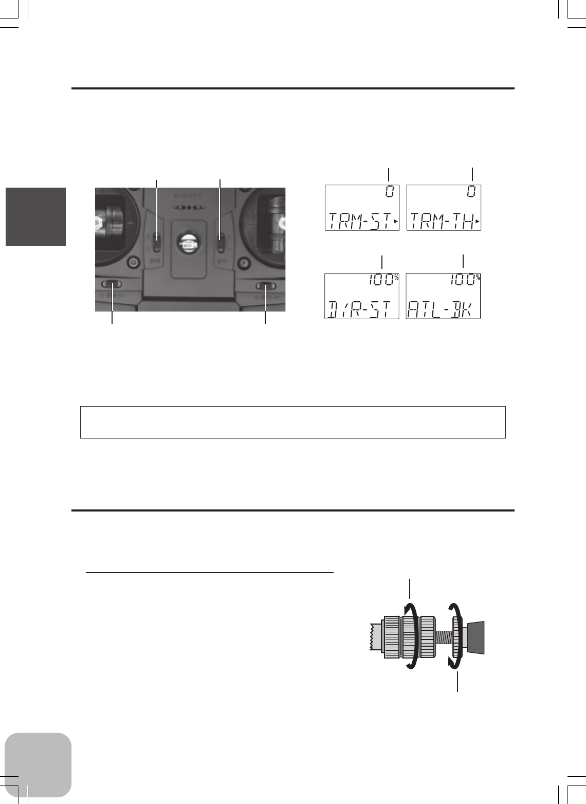
Digital Trim Operation
(Initial settings: DT1: Steering trim, DT2: Throttle trim, DT3=Steering D/R, DT4=Throttle ATL)
Push the lever to the left or right (up or down).
The current position is displayed on the LCD screen for about three seconds when
each digital trim is operated.
Steering trim
position
Throttle trim
position
- Each step is indicated by a tone.
- When the trim exceeds the maximum trim adjust-
ment range, the tone will change pitch and the lever
will not move any farther.
Trim Operation
With the digital trim feature, trim adjustments have no effect on the maximum servo
travel. This prevents the linkages from binding when adjustments are made.
ATL position
Steering D/R rate
Stick Lever Head Adjustment
The length of the lever head of the steering and throttle sticks can be adjusted.
Adjustment
1 Unlock lever head “A” by turning it counter-
clockwise.
2 Adjust the head to the length best for you,
then lock the heads by turning lever head
“A” clockwise and lever head “B” counter-
clockwise.
DT4 DT1
DT2 DT3
Lever head
“B”
Lever head
“A”
17
Before Using
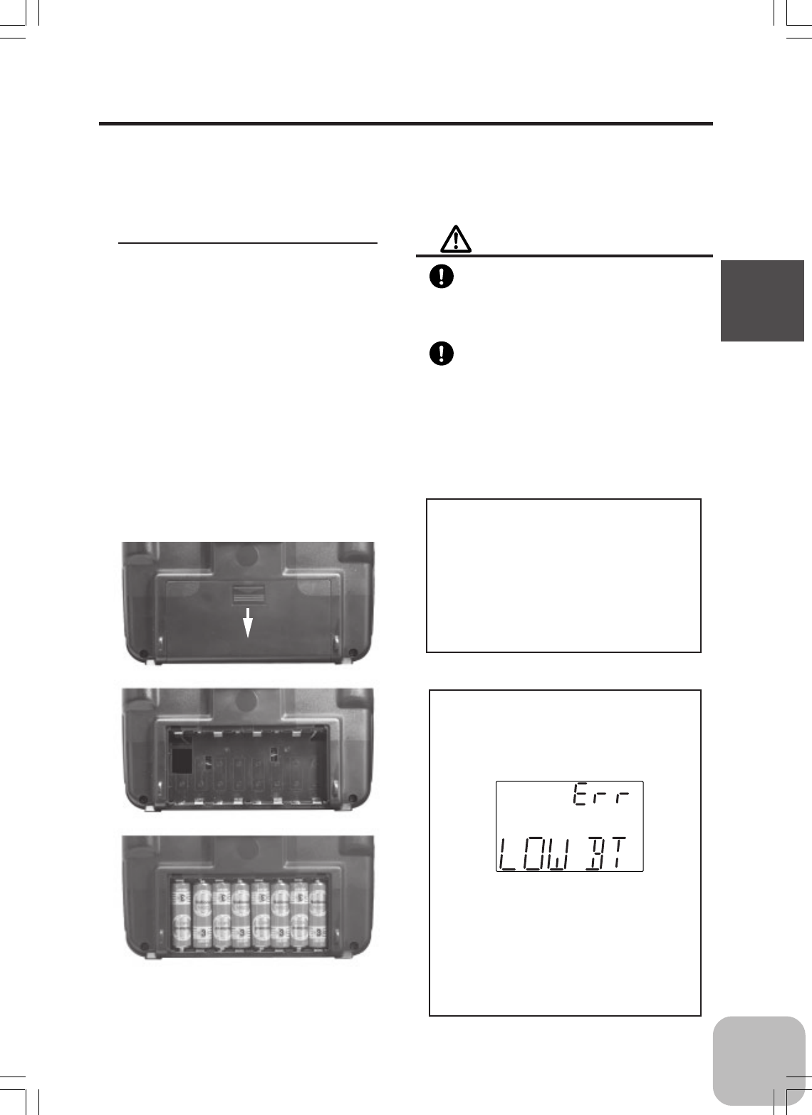
For dry cell battery system
Load the eight batteries in accordance with the polarity markings on the battery
holder. (8 AA Size Batteries)
Battery Replacement
Battery Replacement
1Remove the battery cover from
the transmitter by sliding it in
the direction of the arrow in the
figure.
2Remove the used batteries.
3Load the new AA size batteries.
Pay very close attention to the
polarity markings and reinsert
accordingly.
4Slide the battery cover back
onto the case. Check:
Turn the power switch on the trans-
mitter to the ON position. Check the
battery voltage display on the LCD
screen.
If the voltage is low, check the batter-
ies for insufficient contact in the case
or incorrect battery polarity.
Caution
Always be sure you reinsert the bat-
teries in the correct polarity order.
If the batteries are loaded incorrectly, the
transmitter may be damaged.
When the transmitter will not be
used for any period of time, always
remove the batteries.
If the batteries do happen to leak, clean the
battery case and contacts thoroughly. Make
sure the contacts are free of corrosion.
Low Battery Alarm:
If the transmitter battery voltage
drops below 8.5V, an alarm will
sound and "LOW BT" will be dis-
played on the LCD screen.
The low battery alarm is meant to be a
safety feature only. Do NOT operate
your radio below 9V. Always shut
your radio off as soon as possible af-
ter the low battery warning tone to
avoid loss of control.
18
Before Using
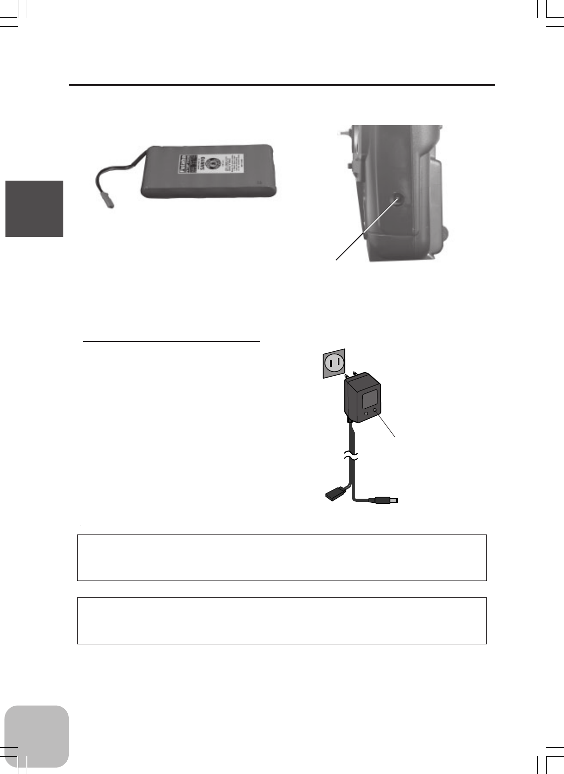
For NiCd battery system
- Always use an NT8F700B NiCd battery.
NiCd battery
NT8F700B
Charging the NiCd Battery
1 Plug the transmitter cord of the
special charger into the charg-
ing jack on the side of the trans-
mitter.
2 Plug the charger into an AC out-
let.
3 Check that the charging LED
lights.
Charger
Transmitter charging
LED
Cord to transmitter
charging jack
When charging the NT8F700B NiCd battery with the special charger, allow about 15
hours for charging. If the transmitter has not been used for some time, cycle the
battery by charging and discharging it two or three times.
Over current protection
The transmitter charging circuit is equipped with an over current protection circuit. If
the battery is charged with a quick charger for other than digital proportional R/C
sets, it may not be fully charged.
AC outlet
Charging jack
19
Before Using
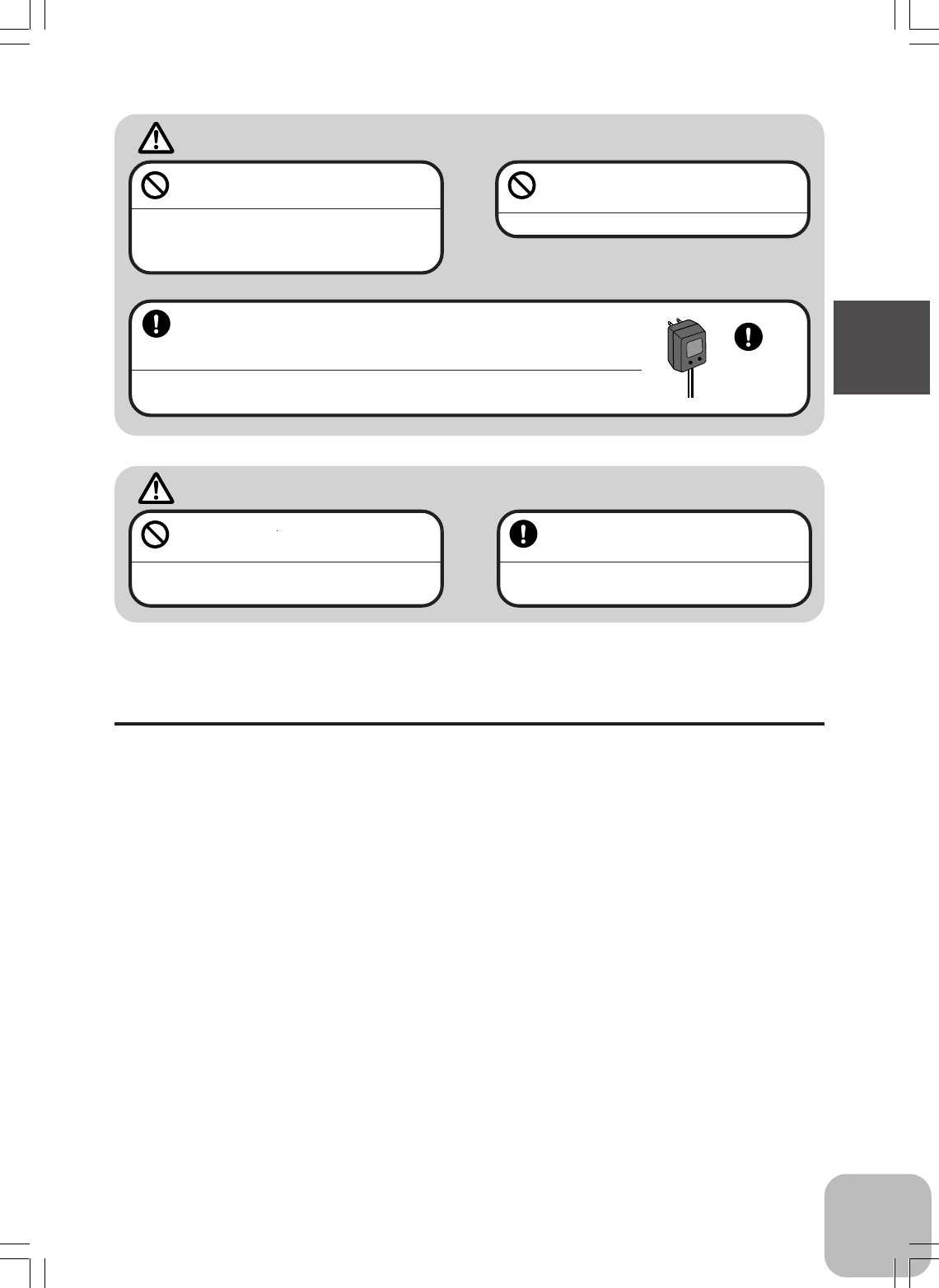
Always use the special charger or a quick charger for digital pro-
portional R/C sets to charge a digital proportional R/C set NiCd
battery.
Overcharging a NiCd battery can result in burns, fire, injuries, or loss of sight due to
overheating, breakage, or electrolyte leakage.
Never try to recharge a dry cell bat-
tery.
The transmitter may be damaged or the battery
electrolyte may leak or the battery may break.
When the charger is not in use, dis-
connect it from the AC outlet.
Do this to prevent accidents and to avoid overheat-
ing.
Caution
Never plug it into an outlet of other
than indicated voltage.
Plugging the charger into the wrong outlet may re-
sult in an explosion, sparking, or fire.
Do not insert and remove the
charger when your hands are wet.
It may cause an electric shock.
Warning
Use the
special
char
g
er.
Set data backup
The set data of each function of the T3GR-2.4G transmitter is stored in a memory
element that does not require a backup battery. Therefore, the transmitter can be used
without paying attention to the backup battery life.
20
Before Using
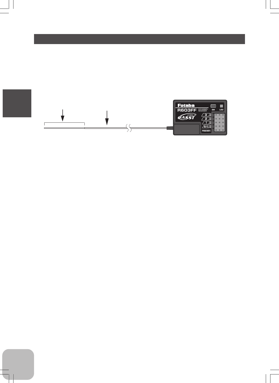
Receiver
For the receiver, servos, and other connections, see page 21.
Connectors
3: CH3 servo (CH3)
2: Throttle servo (CH2)
1: Steering servo (CH1)
B/C: Power connector/DSC connector
RS232C: (for factory use only)
R603FF
receiver
Antenna Coaxial cable
21
Installation
Installation
Warning
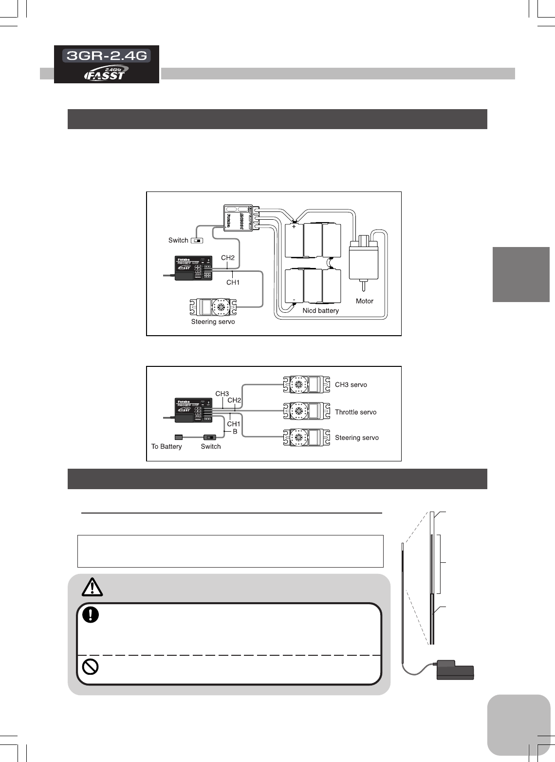
Receiver and Servo Connections
Installation For Electric Powered Models
When connecting and installing the receiver and servos, read the “Installation Safety
Precautions”.
Installation For Gas Powered Models
R603FF
ESC
R603FF
Installation Safety Precautions
Antenna
tube
Antenna
Coaxial
cable
R603FF
Receiver Antenna Installation
Install the R603FF receiver on the car as follows:
Note: The operating range may become shorter, depending on
where the receiver and the antenna are mounted.
•Install the antenna in the higher place as shown in the figure.
•Keep the antenna as for away from the motor, ESC and other
noise sources as possible.
•Put the antenna in the antenna tube to protect it.
•Do not cut the antenna.
•Do not bend the coaxial cable. Doing so causes damage.
22
Installation
Warning
Connector Connections
Be sure the receiver, servo and con-
nectors are fully and firmly con-
nected.
If vibration from the model causes a connector to work
loose while the model is in operation, you may lose
control .
Electronic speed control
Install the heat sinks where they will
not come in contact with aluminum,
carbon fiber or other parts that con-
duct electricity.
If the Electronic speed control heat sinks touch other
materials that conduct electricity a short circuit could
occur. This could result in loss of control and damage
to the system.
Receiver Vibration Damping and
Waterproofing
(Car)
Dampen the vibration to the receiver
by mounting it to the chassis or
mounting plate with thick, double-
sided tape in electric powered mod-
els. In gas powered models, wrap the
receiver in foam and mount it where
the vibration is the least prevalent.
(Boat)
Dampen the vibration to the receiver
by wrapping it in foam. Waterproof by
placing it in a plastic bag or make the
radio box in your model watertight.
If the receiver is subjected to strong vibration or shock
erratic or loss of control may occur. If any moisture
comes in contact the receiver and servos you may
experience the same result as well as damage to the
system.
Servo Throw
Operate each servo over its full stroke
and be sure the linkage does not bind
or is loose.
The continuous application of unreasonable force to a
servo may cause damage and excessive battery
drain.
Servo Installation
When you install the servos always
use the rubber grommets provided in
servo hardware bags. Mount the ser-
vos so they do not directly come in
contact with the mount.
If the servo case comes in direct contact with the
mount, vibration will be directly transmitted to the
servo.
If this condition continues for a long time the servo
may be damaged and control will be lost.
Motor Noise Suppression
Always install capacitors to suppress
noise when electric motors are used.
If capacitors are not properly installed you could expe-
rience erratic operation and reduced range as well as
loss of control.
Other Noise Suppression Methods
Be sure there are no metal parts in
your model which under vibration
could come in contact with other
metal parts.
Metal to metal contacts under vibration will emit a high
frequency noise that will affect the receiver's perfor-
mance. You could experience erratic operation and
reduced range as well as loss of control.
23
Initial Set-Up
Initial Set-Up
How to link the transmitter and the receiver
Each transmitter has an individually assigned, unique ID code. In order to start opera-
tion, the receiver must be linked with the ID code of the transmitter with which it is
being paired. Once the link is made, the ID code is stored in the receiver and no
further linking is necessary unless the receiver needs to be used with an other trans-
mitter. (For T/R set, the link is already done at factory.)
Link procedure
1. Bring the transmitter and the receiver close to each other, within one meter.
2. Turn on the transmitter.
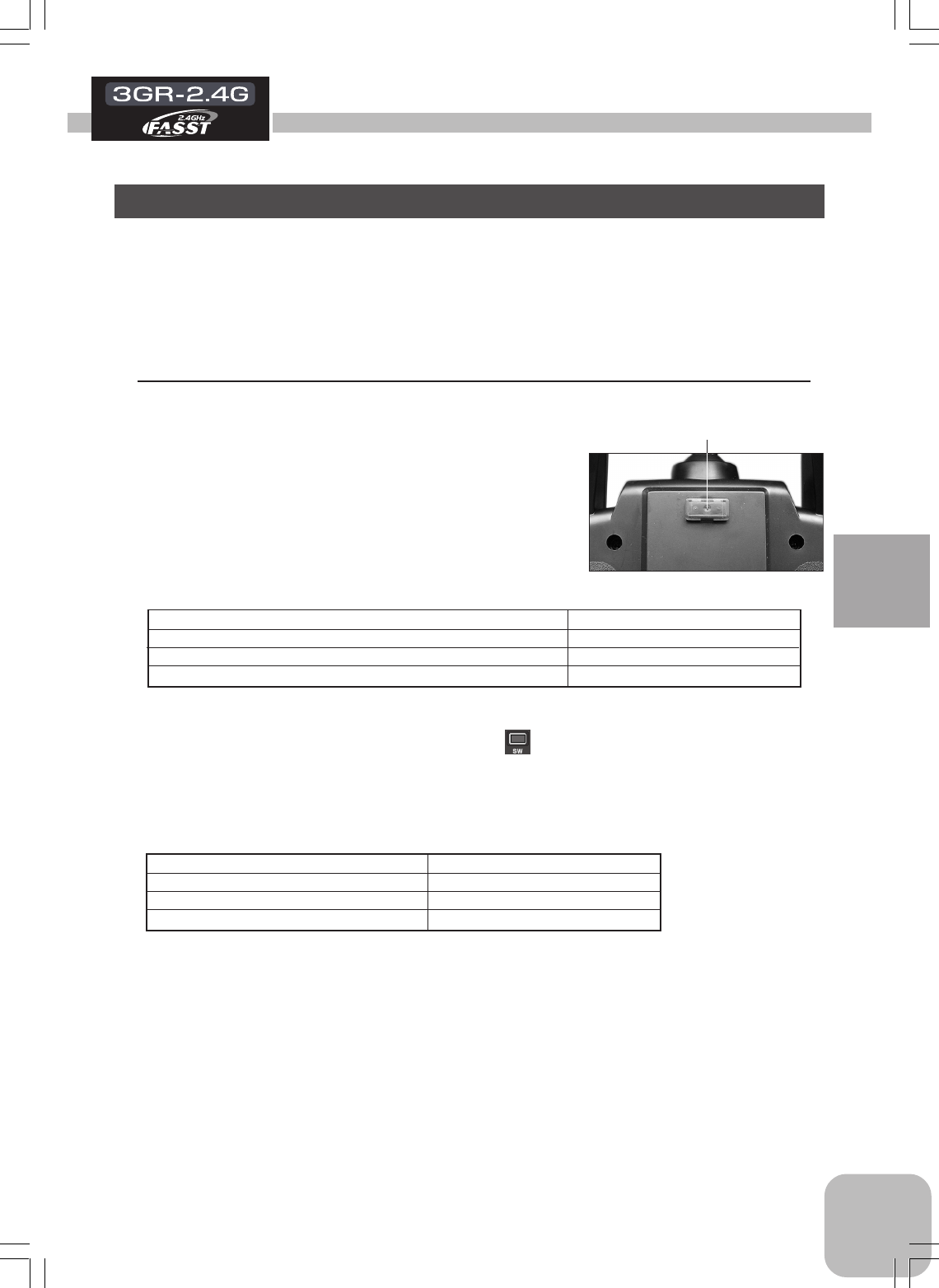
3.
Check the LED that is placed on the back side of the
transmitter to see if the RF signal is transmitted.
When the green LED is solid ON, the RF signal is
transmitted.
*Please refer the table below for LED status vs transmitter's condition.
LED status vs transmitter's condition:
Parameter check for 0.5 seconds after power-on Red: On
Transmitting signals Green: On
F/S is activated by the F/S switch of the transmitter. (PPM mode) Green: Blink
Unrecoverable failure (EEPROM, etc.) Red and Green turn on alternatively.
4. Turn on the receiver.
5. Push the tactile switch of the receiver.
6. When the link is complete, the LED in the receiver changes to solid green.
*Please refer the table below for LED status vs receiver's condition.
LED status vs receiver's condition:
No signal reception Red : On
Receiving signals Green: On
Receiving signals, but ID is unmatched. Green: Blink
Unrecoverable failure (EEPROM, etc.) Red and Green turn on alternatively.
LED
24
Initial Set-Up
Preparations (Transmitter)
Before setting the transmitter functions, check and set items below.
Model number
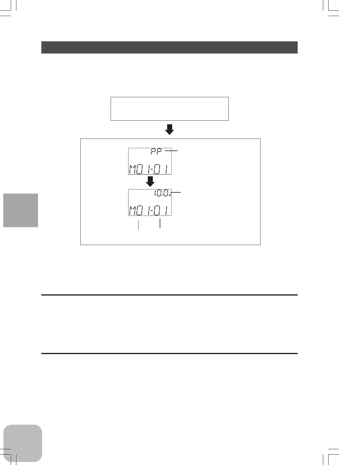
Turn on the transmitter power.
Model name
(displayed for about one second)
1. Model Number Check
When the power switch is turned on, the current selected model number is displayed.
Check if this number is the model number you want to set-up. To change the model
number, use the Model Select function (page 48).
Modulation mode
PP: PPM mode
HRS: HRS mode
Battery voltage
(Display when power switch is turned on)
2. Modulation Mode Check
The T3GR-2.4G transmitter output signal format can be changed. (HRS/PPM) Check
if the modulation mode is set to the desired mode.
If this setting is incorrect, change it with the HRS/PPM Select function (page 53).
25
Initial Set-Up
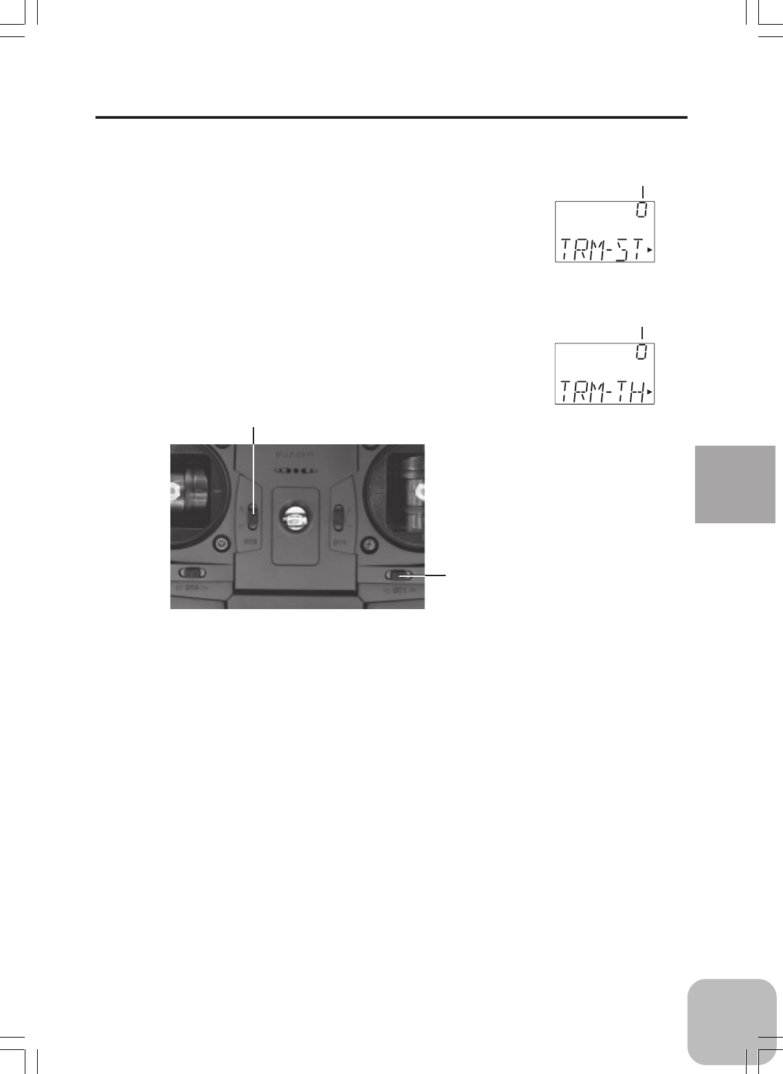
3. Trims Initial Set-Up
- Steering trim (DT1) check
At initial set-up, steering trim is assigned to digital trim
DT1. Operate the DT1 lever and check if the steering
trim value on the screen changes. After checking the
trim, set the trim value to the center (0) position.
- Throttle trim (DT2) check
At initial set-up, throttle trim is assigned to digital trim
DT2. Operate the DT2 lever and check if the throttle
trim value on the screen changes. After checking the
trim, set the trim value to the center (0) position.
Steering trim
position
Throttle trim
position
DT2
DT1
26
Initial Set-Up
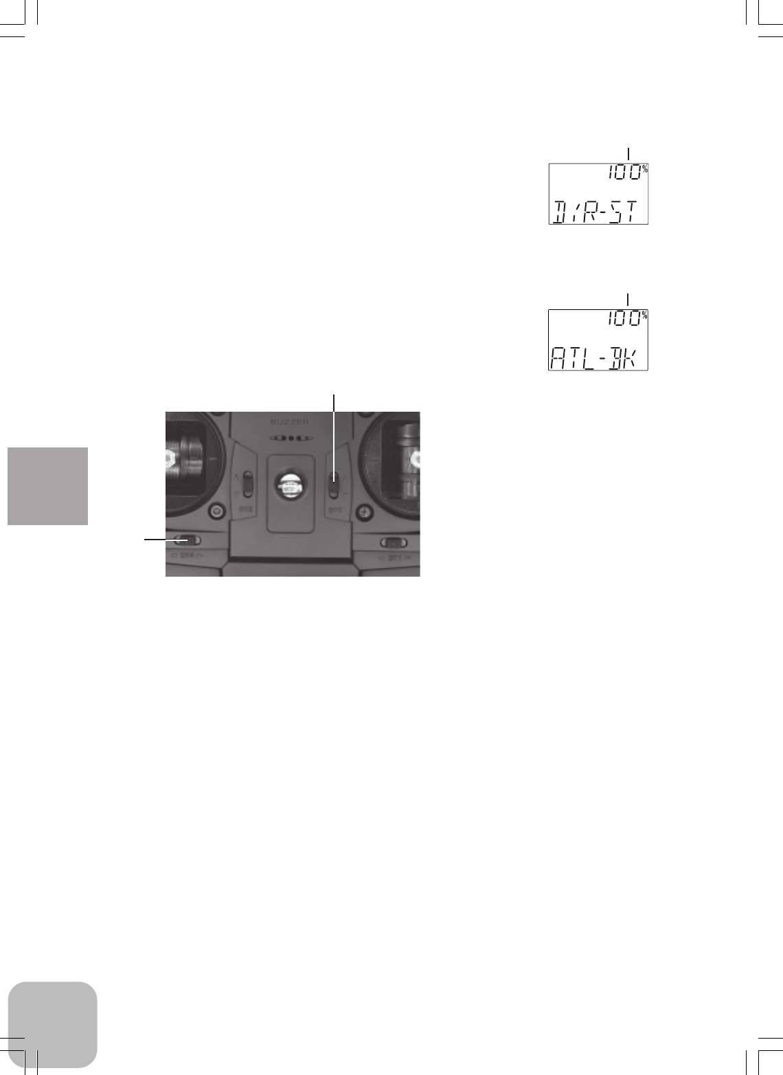
- Steering dual rate (DT3) check
At initial set-up, steering dual rate is assigned to digital
trim DT3. Operate the DT3 lever and check if the D/R
value displayed on the screen changes. After checking
D/R, set the steering dual rate to 100%.
- Throttle ATL (DT4) check
At initial setting, throttle ATL is assigned to digital
trim DT4. Operate the DT4 lever and check if the ATL
value displayed on the screen changes. After checking
ATL, set throttle ATL to 100%.
Steering D/R
value
Throttle ATL
position
DT3
DT4
27
Initial Set-Up
(Set-Up Procedure When Installed In a Car)
When installing the servos in a car, performing function set-up in the following order
is recommended.
1. Set up the servo trims (page 22).
2. Set the servo direction of operation using the Reverse
function. (Page 47)
The servo installation method and linkage direction depend
on the kit. Therefore, the servo operation direction may have
to be reversed relative to transmitter operation. Before in-
stalling the servo, check the operating direction and set it us-
ing the Reverse function.
3. Set the subtrim and adjust the servo neutral point. (Page
46)
4. Set EPA of each channel and adjust the servo throw
(travel). (Page 30)
28
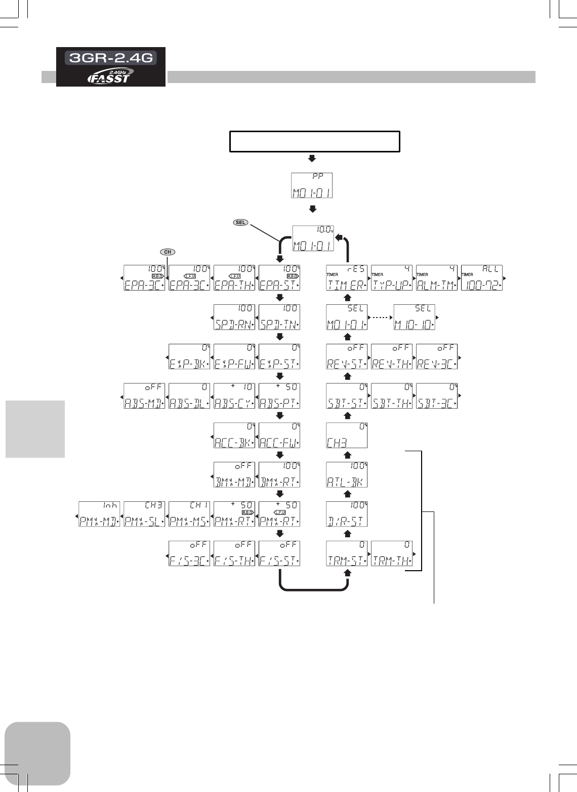
Function Map
Function Map
Power switch turned on
The current modulation mode is
displayed for about two seconds.
Press "SEL" key to select
the desired function screen.
Press it for one second or
more to scroll to the opposite
direction.
Press "CH" key to select
the next set-up screen.
(Initial Screen)
Digital trim DT1 - DT4 display
The current position is displayed on the LCD screen
for about two seconds when each digital trim is operated.
End Point Adjuster Timer
Model Select
Channel Reverse
Subtrim
Channel 3 Position
ATL Function
Steering D/R
Trim
Steering Speed
Steering EXP/Throttle EXP
ABS Function
Throttle Acceleration
Brake mixing
Programmable Mixing
Fail Safe Function (HRS system only)
29
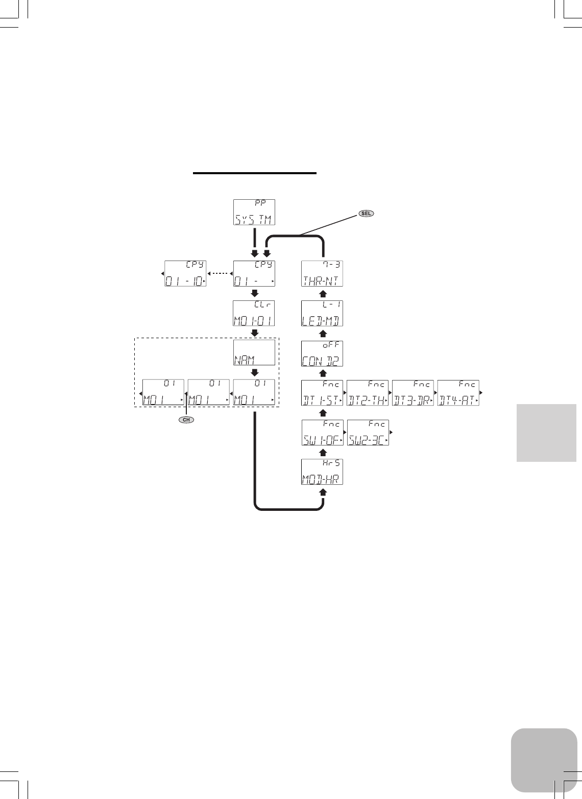
Function Map
System Functions
(displayed for about
one second)
Tu rn on the power switch while pressing "SEL" key.
LED Mode Selection
Throttle Neutral Adjuster
Condition 2 Selection
Model Copy
Function Select Lever
Model Reset
Function Select Switch
HRS/PPM Select
Model Name
Press "SEL" key to select
the desired function screen.
Press it for one second or
more to scroll to the opposite
direction.
Press "CH" key to select
the next set-up screen.
30
Functions
Functions
End point adjuster/EPA
Use this when performing left and right steering angle adjustments, throttle high side/
brake side operation amount adjustment, and channel 3 servo up side/down side op-
eration amount adjustment during linkage.
- Corrects the maximum steering angle and left and right steering angles when there
is a difference in the turning radius due to the characteristics, etc. of the vehicle.
Maximum steering angle
The EPA function basically determines the maximum steering angle of each channel.
The functions shown below may have been adjusted, or the operating range set by
EPA function may be exceeded. Check the linkage each time the following functions
are adjusted.
- Sub trim (all channels)
- Throttle Acceleration (Brake side)
- Brake mixing rate
- Program mixing slave side (all channels)
ATL trim
ATL trim allows adjustment of the brake side operation amount during operation.
Therefore, when the operating angle is adjusted with throttle EPA, ATL trim must
also be taken into account.
Warning
Make sure that the knuckle stopper is not contacted
during steering operation and that unreasonable
force is not applied to the servo during other channel
operation.
If unreasonable force is applied to the servo horn at the knuckle stopper
during steering operation, the servo may malfunction and the model may
run out of control.
Decide the EPA value
at the contact point.
Caution!
Be sure that the steering
servo does not bind.
31
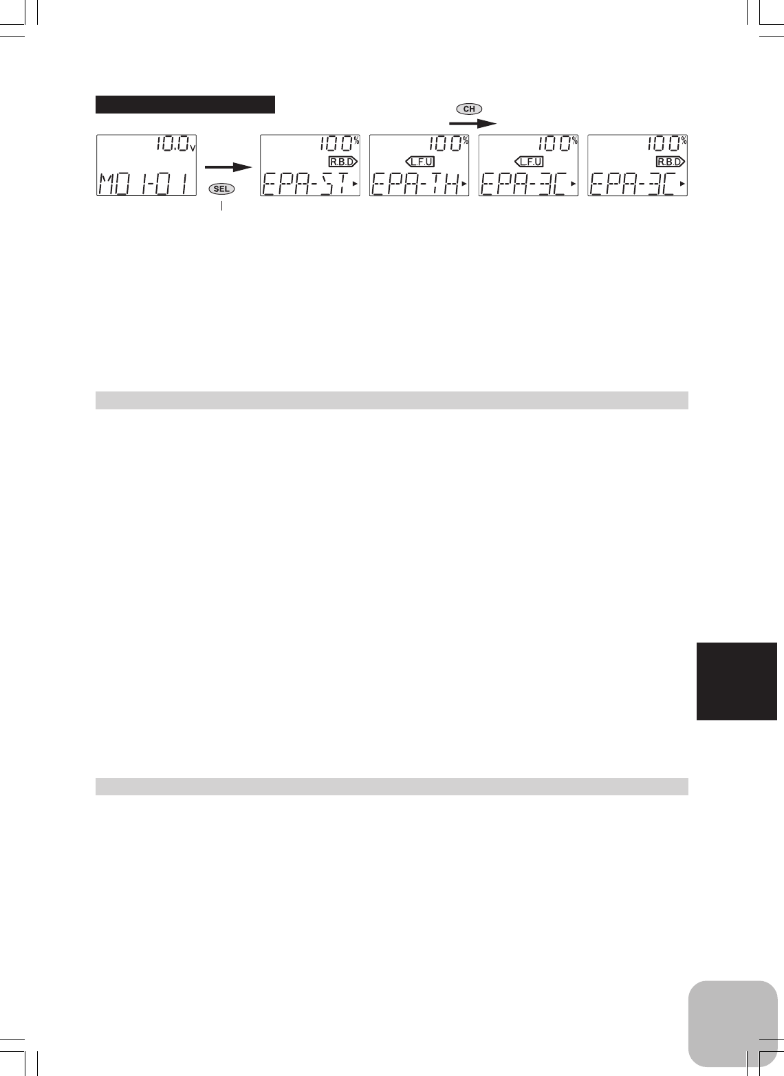
Functions
Steering (EPA) adjustment
(Preparation)
- Before setting up the steering EPA, set the steering D/R lever (initial setup: DT3) to
the maximum steering angle position 100%.
- Select setup item "ST" and make the following adjustments:
1 Steering (left side) adjustment
Turn the steering stick fully to the left and use the (+) and (-) buttons to
adjust the steering angle.
2 Steering (right side) adjustment
Turn the steering stick fully to the right and use the (+) and (-) buttons to
adjust the steering angle.
3 When adjusting the EPA of another channel immediately after this, see the
adjustment method for that channel. When ending adjustment, return to
the initial screen by pressing the (SEL) button.
(Initial screen)
Press "SEL" key to select the
desired function screen.
Calling the setup screen
Adjustment range
0~120% (each channel, each direc-
tion)
Adjustment buttons
- Use the (+) and (-) keys to make ad-
justments.
- Return to the initial value by pressing
the (+) and (-) buttons simultaneously
(approx. 1 sec).
Setup items
ST-L.F.U : Steering (left side)
ST-R.B.D : Steering (right side)
TH-L.F.U : Throttle (forward side)
TH-R.B.D : Throttle (brake side)
3C-L.F.U : 3rd channel (up side)
3C-R.B.D : 3rd channel (down side)
(Setup screen)
Press "CH" key to select the next set-
up screen.
Throttle (EPA) adjustment
(Preparation)
- Before setting the throttle EPA, set the throttle ATL lever (initial setup: DT4) to the
maximum steering angle position 100%.
- Select setup item "TH" and make the following adjustments:
1 Throttle (forward side) adjustment
Push the throttle stick fully to the high side and use the (+) and (-) buttons to adjust
the steering angle. However, when using an FET amp, set to 100%.

32
Functions
3rd channel servo (EPA) adjustment
(Preparation)
- Select setup item "3C-L.F.U" and make the following adjustments:
(3rd channnel initial setup: SW2)
1 3rd channel servo (up side) adjustment
Use the (+) and (-) buttons to adjust the steering angle.
2 3rd channel servo (down side) adjustment
Select setup item "3C-R.B.D" and use the (+) and (-) buttons to adjust the
steering angle.
3 When adjusting the EPA of another channel immediately after this, see the
adjustment method for that channel. When ending adjustment, return to
the initial screen by pressing the (SEL) button.
2 Throttle (brake side/reverse side) adjustment
Pull the throttle stick fully to the brake side and use the (+) and (-) buttons
to adjust the steering angle. However, when using an FET amp, set to
100%.
3 When adjusting the EPA of another channel immediately after this, see the
adjustment method for that channel. When ending adjustment, return to
the initial screen by pressing the (SEL) button.
33
Functions
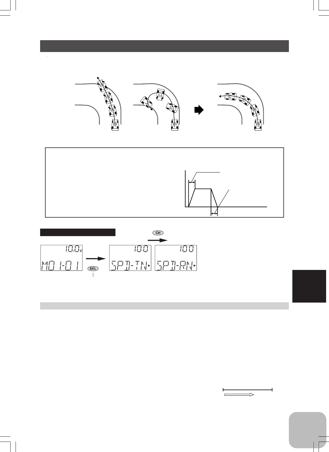
Setup item
SPD-TN: TURN direction
SPD-RN: RETURN direction
Adjustment range
0~100% (each direction)
Adjustment buttons
- Use the (+) and (-) buttons to make
adjustments.
- Return to the initial value by pressing
the (+) and (-) buttons simultaneously
(approx. 1 sec).
Steering Speed (SPD) adjustment
(Preparation)
- Select setup item "SPD-TN" and make the following
adjustments:
1 "TN" direction adjustment
Use the (+) and (-) buttons to adjust the delay
amount.
2 "RN" direction adjustment
Select setup item "SPD-RN" and use the (+)
and (-) buttons to adjust the delay amount.
3 When ending adjustment, return to the initial
screen by pressing the (SEL) button.
100% 1%
サーボの動作が遅くなる。
Setting range: 1~100%
At 100%, there is no delay.
At 1%, the delay is approximately 1.5
seconds.
Servo operation is delayed.
操作時のスピード可変範囲
時間
(約1.5∼0.1秒)
戻りのスピード可変範
囲
(約1.5∼0.1秒)
ス
テ
ィ
ッ
ク
操
作
"TURN"方向
"RETN"方向
Steering Speed/SPD
Quick steering operation will cause momentary understeering, loss of speed, or spin-
ning. This function is effective in such cases.
Understeering
Spin
Smooth cornering
Steering speed not set Steering speed set
Operation
- This function limits the maximum speed of
the steering servo. (Delay function)
- The steering speed when the steering stick
is operated (TN direction) and returned (RN
direction) can be independently set.
TN direction
Turning speed adjustment range
Stick operation
RN direction
Return speed adjust-
ment range
- If the steering wheel is turned
slower than the set speed, the steer-
ing servo is not affected. Time
(Initial screen)
Press "SEL" key to select the
desired function screen.
Calling the setup screen
(Setup screen)
Press "CH" key to select the next set-
up screen.
34
Functions
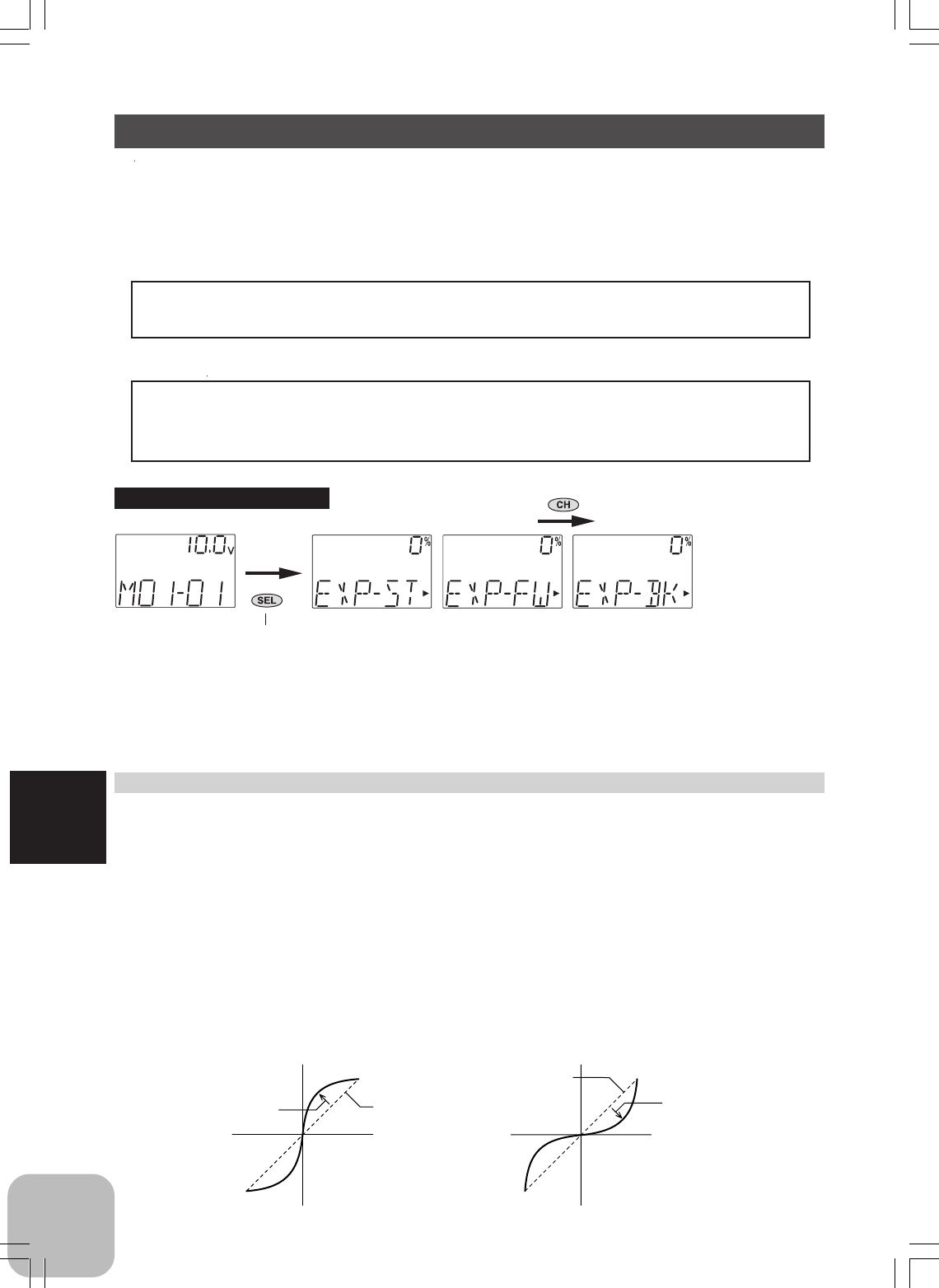
Steering EXP, Throttle EXP / EXP
This function is used to change the sensitivity of the steering servo around the neutral
position and makes throttle stick high side and brake side direction servo operation
quicker or milder. It has no effect on the maximum servo travel.
Racers Tip
When the setting is not determined, or the characteristics of the model are unknown,
start with 0%. (When EXP is set to 0%, servo movement is linear.)
Advice (Throttle EXP)
When the course conditions are good and there is no sense of torque at the power unit,
set each curve to the + side (quick side). When the road surface is slippery and the
drive wheels do not grip it, set each curve to the - minus (mild) side.
Steering EXP adjustment
(Preparation)
- Select setup item "EXP-ST" and make the following adjustments:
1 When you want to quicken steering operation, use the (+) button to adjust
the + side. When you want to make steering operation milder, use the (-)
button to adjust the - side.
2 When adjusting the EXP rates of another channel immediately after this,
see the adjustment method for that channel. When ending adjustment,
return to the initial screen by pressing the (SEL) button.
Setup item
EXP-ST: Steering EXP rate
EXP-FW : Forward side
EXP rate
EXP-BK : Brake side EXP rate
Adjustment range
-100~0~+100%
Adjustment buttons
- Use the (+) and (-) buttons to make
adjustments.
- Return to the initial value by pressing
the (+) and (-) buttons simultaneously
(approx. 1 sec).
サーボ動作量
ステアリング
スティック
動作量
0%(ノーマル)
+1%∼+100%
(クイック)
サーボ動作量
ステアリング
スティック
動作量
0%(ノーマル) -1%∼ -100%
(マイルド)
(Quick) (Mild)
Servo travel Servo travel
0% (normal)
(Initial screen)
Press "SEL" key to select the
desired function screen.
Calling the setup screen
(Setup screen)
Press "CH" key to select the next set-
up screen.
+1% ~ +100% (quick) 0% (normal) -1% ~ -100% (mild)
Steering wheel travel Steering wheel travel

35
Functions
Throttle EXP Adjustment
(Preparation)
- Select setup item "EXP-FW" and make the following adjustments:
1 Forward side adjustment
Use the (+) button to adjust the + side when you want to quicken the rise
and use the (-) button to adjust the - side when you want to make the rise
milder.
2 Brake side adjustment
Select setup item "EXP-BK" and use the (+) button to adjust the + side
when you want to quicken the rise and use the (-) button to adjust the - side
when you want to make the rise milder.
3 When adjusting the EXP rates of another channel immediately after this,
see the adjustment method for that channel. When ending adjustment,
return to the initial screen by pressing the (SEL) button.
36
Functions
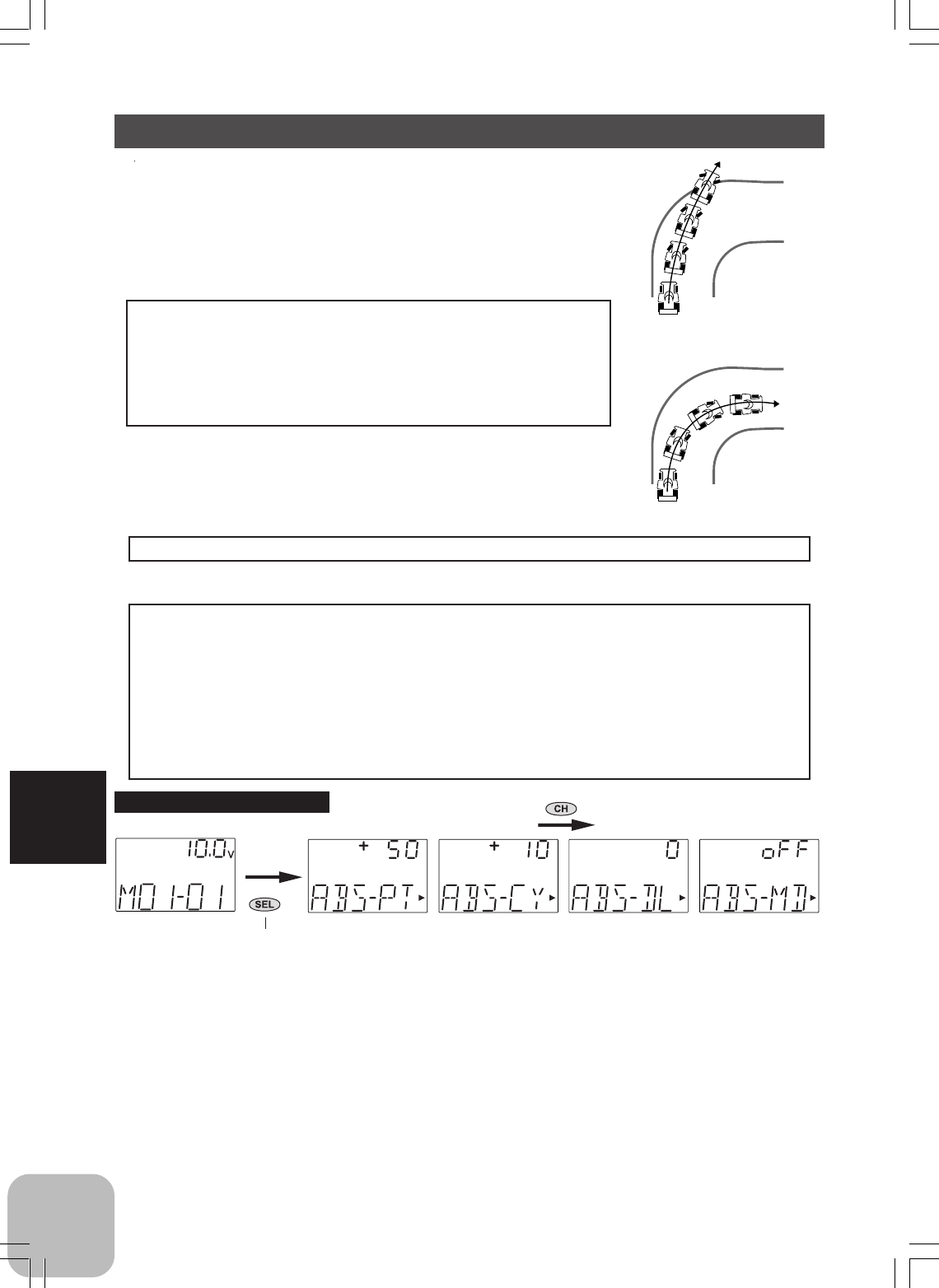
Setup items
ABS-PT : Brake return amount
ABS-CY : Cycle speed
ABS-DL : Delay amount
ABS-MD : Function ON/Off
Adjustment buttons
- Use the (+) and (-) buttons to make
adjustments.
- Return to the initial value by pressing
the (+) and (-) buttons simultaneously
(approx. 1 sec).
Brake return amount:
0 ~ 50 ~ 100
Initial value; 50
Cycle speed:
1~ 30
Initial value; 10
Delay amount:
0 ~ 100
Initial value; 0
A.B.S. Function / ABS
When the brakes are applied while cornering with a 4 Wheel
Drive or other type of vehicle, understeer may occur. The
generation of understeer can be eliminated and corners can
be smoothly cleared by using this function.
Operation
- When the brakes are applied, the throttle servo will pulse
intermittently. This will have the same effect as pumping
the brakes in a full size car.
- The brake return amount, pumping cycle, and delay
amount can be adjusted.
Without A.B.S.
With A.B.S.
Operation Display
When the A.B.S. function is activated, the LED flashes.
Fail Safe Unit
When the 3GR-2.4G system (PPM mode) is used with the Futaba fail safe unit
(FSU), it will operate as described below.
- When the FSU is connected to the throttle channel, and the A.B.S. function has been
activated, the FSU LED will flash each time the servo operates. The reason for this is
that the FSU responds to sudden data changes caused by A.B.S. function pumping
operation. It does not mean that the fail safe function is activated. The servo will not
be affected.
(Initial screen)
Press "SEL" key to select the
desired function screen.
Calling the setup screen
(Setup screen)
Press "CH" key to select the next set-
up screen.
37
Functions
0% 100%
A.B.S function adjustment
(Preparation)
- Select setup item "ABS-MD" and make the following adjustments:
1 (Function ON/OFF)
Set the function to the active state by pressing the (+) or (-) button.
OFF : Function OFF
ON : Function ON
2 (Brake return amount adjustment)
Select setup item "ABS-PT" and use the (+) and (-) buttons to adjust the
return amount.
"0" : No return
"50" : Return to the 50% position of the brake operation amount
"100" : Return to the neutral position.
3 (Cycle speed adjustment)
Select setup item "ABS-CY" and use the (+) and (-) buttons to adjust the
speed.
- The lower the set value, the faster the cycle speed.
4 (Delay amount setup)
Select setup item "ABS-DL" and use the (+) and (-) buttons to adjust the
delay amount.
"0" : A.B.S. function performed without any delay
"50" : A.B.S function performed after an approximate 0.7 sec delay.
"100" : A.B.S. function performed after an approximate 1.4 secs delay.
5 When ending adjustment, return to the initial screen by pressing the (SEL)
button.
38
Functions
Forward acceleration amount
0~100
Initial value: 0
Brake side acceleration amount
0~100
Initial value: 0
Adjustment buttons
- Use the (+) and (-) buttons to make
adjustments.
- Press the (+) and (-) buttons simulta-
neously (approx. 1 sec) to return to the
initial screen.
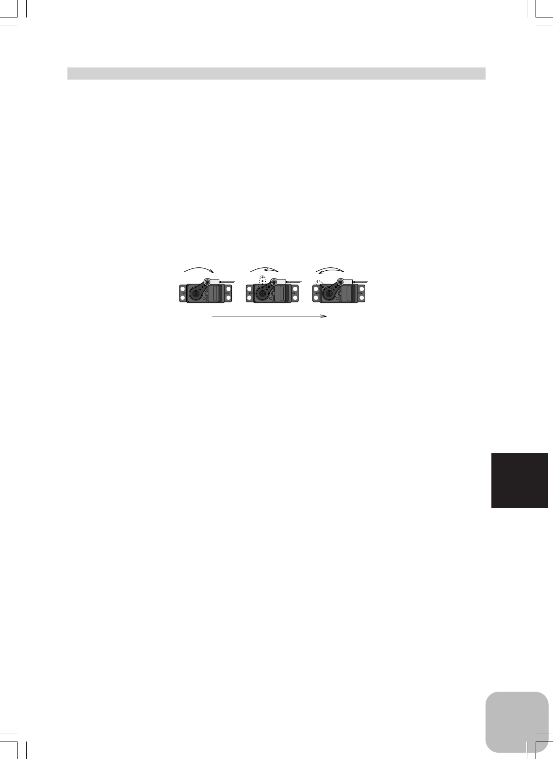
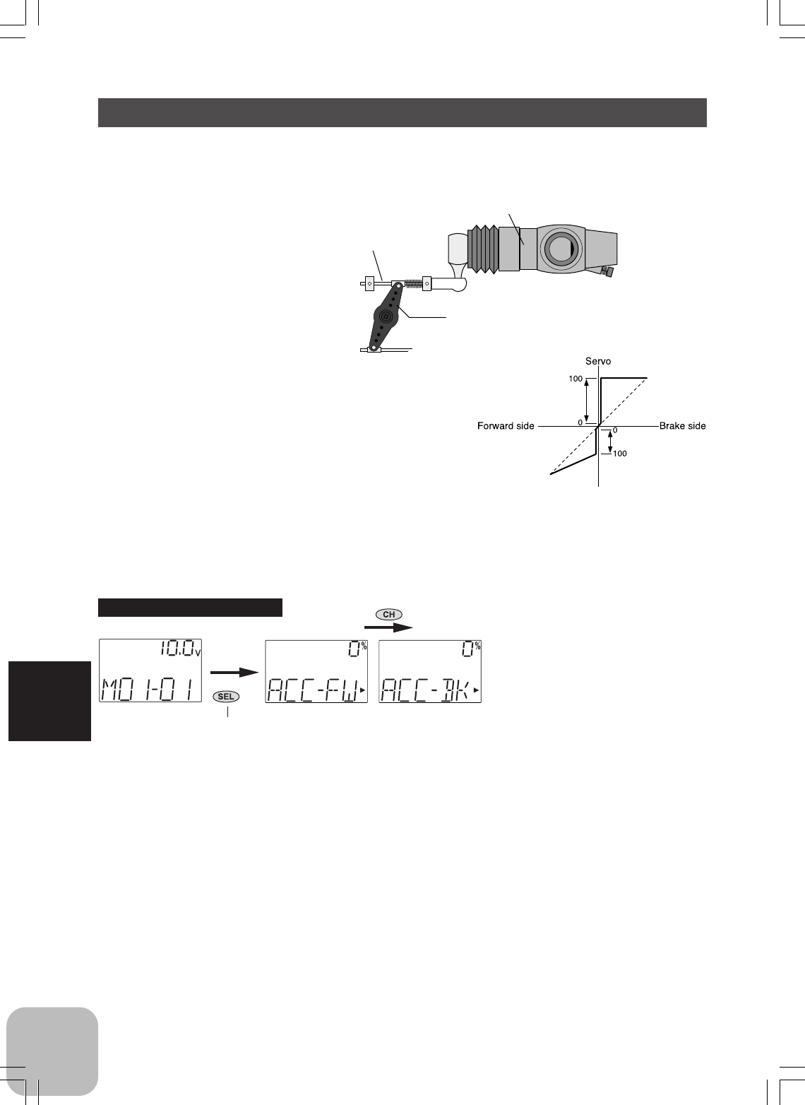
Carburetor
Servo horn
Brake side
A slight clearance is required at the linkage, but the
throttle acceleration function acts to reduce the time
lag caused by this clearance.
Throttle Acceleration / ACC
Gasoline engine cars have a small time lag at both the forward side and brake side
because a certain clearance is necessary at the linkage. Reducing this time lag at the
transmitter side provides the same sharp response as electric motor cars.
Operation
- Operation near the throttle stick neutral position
becomes a sharp rise.
- The forward and brake sides can be set separately.
Set value
The standard value (100% point) of this setup effects the operation amount set by
throttle EPA function.
Setup items
ACC-FW : Forward side acceleration
amount
ACC-BK : Brake side acceleration
amount
BRAKE
FORWARD
(Initial screen)
Press "SEL" key to select the
desired function screen.
Calling the setup screen
(Setup screen)
Press "CH" key to select the next set-
up screen.

39
Functions
Throttle acceleration adjustment
(Preparation)
- Select setup item "ACC-FW" and make the following adjustments.
1 (Forward acceleration amount adjustment)
Use the (+) and (-) buttons to adjust the acceleration amount.
"0": No acceleration
"100": Maximum acceleration (Approximately 1/2 of the forward side steering angle)
2 (Brake side acceleration amount adjustment)
Select setup item "ACC-BK" and use the (+) and (-) buttons to adjust the
acceleration amount.
"0": No acceleration
"100": Maximum acceleration (Brake side maximum steering angle)
3 When ending adjustment, return to the initial screen by pressing the (SEL)
button.
40
Functions
Brake mixing adjustment
(Preparation)
- Select setup item "BMXMD" and make the following adjustments.
1 (Function ON/OFF)
Set the function to the "ON" state by pressing the (+) or (-) button.
OFF: Function OFF
ON: Function ON
2 (Mixing amount adjustment)
Select setup item "BMX-RT" and use the (+) and (-) buttons to adjust the
mixing amount.
- Mixing amount can be adjusted within the 0~120% range.
3 When ending adjustment, return to the initial screen by pressing the (SEL)
button.
Adjustment buttons
- Use the (+) and (-) buttons to make
adjustments.
- Press the (+) and (-) buttons simulta-
neously (approx. 1 sec) to return to the
initial screen.
Mixing rate
0 ~ 100 ~ 120
Initial value: 100
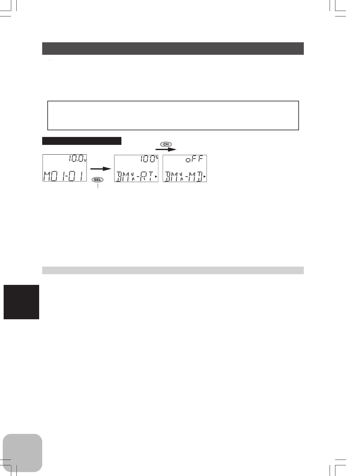
Brake Mixing / BMX
Use this mixing when the front and rear brakes must be adjusted independently, such
as in 1/5GP cars, etc. This mixing uses the 2nd channel to control the rear brakes and
the 3rd channel to control the front brakes.
Operation
- When braking, mixing is applied to 2nd channel and to 3rd channel.
- Mixing rate setting are possible.
- The set value of A.B.S. functions is reflected.
(Initial screen)
Press "SEL" key to select the
desired function screen.
Calling the setup screen
(Setup screen)
Press "CH" key to select the next set-
up screen.
Setup items
BMX-RT: Mixing rate
BMX-MD: Function ON/OFF
41
Functions
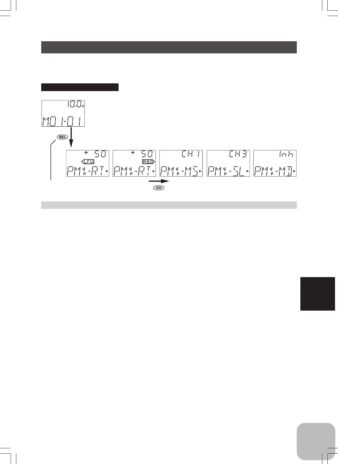
Programmable Mixing / PMX
This function allows you to apply mixing between the steering, throttle, and channel
3 channels.
Program mixing adjustment
(Preparation)
- Use the function select switch function (page 54) to select the switch (as desired.)
- Select setup item "PMX-MD" and make the following adjustments.
1 (Function ON/OFF)
Set the function to the "ON" state by pressing the (+) or (-) button.
"INH": Function OFF, "ON": Function ON, "OFF": Switch OFF
2 (Master channel)
Select setup item "PMX-MS" and select the master channel by pressing
the (+) or (-) button.
3 (Slave channel)
Select setup item "PMX-SL" and select the slave channel by pressing the
(+) or (-) button.
4 (Mixing amount adjustment)---upper item
Select setup item "PMX-RT(L.F.U)" and use the (+) and (-) buttons to ad-
just the mixing amount.
5 (Mixing amount adjustment)---lower item
Select setup item "PMX-RT(R.B.D)" and use the (+) and (-) buttons to ad-
just the mixing amount.
6 When ending adjustment, return to the initial screen by pressing the (SEL)
button.
Setup items
PMX-RT(L.F.U): Mixing rate (Left
side)
PMX-RT(R.B.D.): Mixing rate (Right
side)
PMX-MS: Master channel
PMX-SL: Slave channel
PMX-MD: Function ON/OFF
Mixing amount
-100~+50~+100
Initial value: +50
Adjustment buttons
- Use the (+) and (-) buttons to make
adjustments.
- Press the (+) and (-) buttons simulta-
neously (approx. 1 sec) to return to the
initial screen.
(Initial screen)
Press "SEL" key to select the
desired function screen.
Calling the setup screen
(Setup screen)
Press "CH" key to select the next set-
up screen.
42
Functions
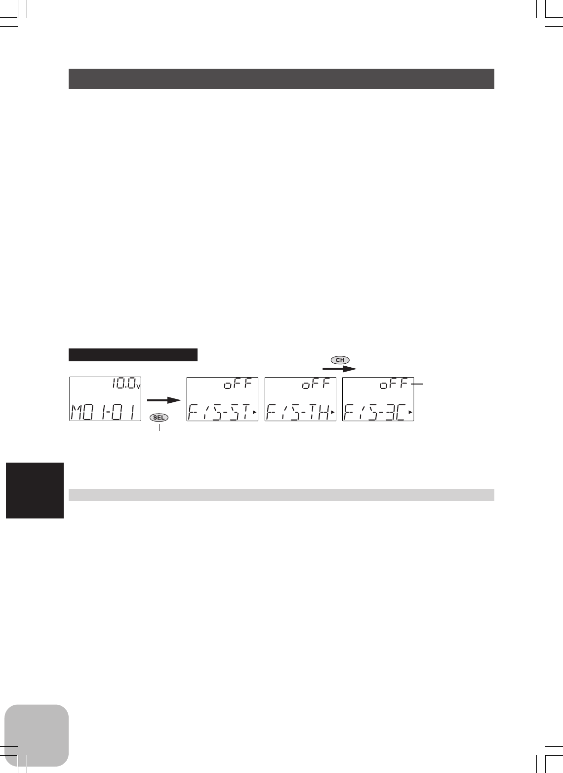
Fail Safe Function/FAIL SAFE
(This function can only be used with HRS system.)
Fail safe function
This function moves the steering, throttle and channel 3 servos to a preset position
when the receiver cannot receive the signal from the transmitter for some reason.
When the servo operation position is not set, this function operates so that the servos
remain in the position they were in immediately before reception was lost. When the
signal from the transmitter can be received again, this function automatically resets.
- For gasoline engine cars, it is recommended that the throttle channel be set to the
direction that applies the brakes.
Battery fail safe function
When the receiver battery voltage drops to a certain voltage or less, this function
moves the throttle servo to the position set by fail safe function. When the voltage
recovers, this function automatically resets.
Setup items
F/S-ST: Steering setting
F/S-TH: Throttle setting
F/S-3C: Channel 3 setting
Fail safe function setup
(Preparation)
- Select the desired channel setup item and make the following adjustments.
1 (Servo position setup)
When the fail safe function operates, the steering stick, the throttle stick or
channel 3 lever remains in the desired operation position. When the (+)
and (-) buttons are pressed simultaneously for about 1 second, the servo
position is displayed and you can confirm that the function was set.
When you want to release the setting, press the (+) or (-) button. "OFF" is
displayed.
(Each channel can be set similarly.)
2 When ending adjustment, return to the initial screen by pressing the (SEL).
The servo position is
displayed when the
fail safe function
was set up.
(Initial screen)
Press "SEL" key to select the
desired function screen.
Calling the setup screen
(Setup screen)
Press "CH" key to select the next set-
up screen.
43
Functions
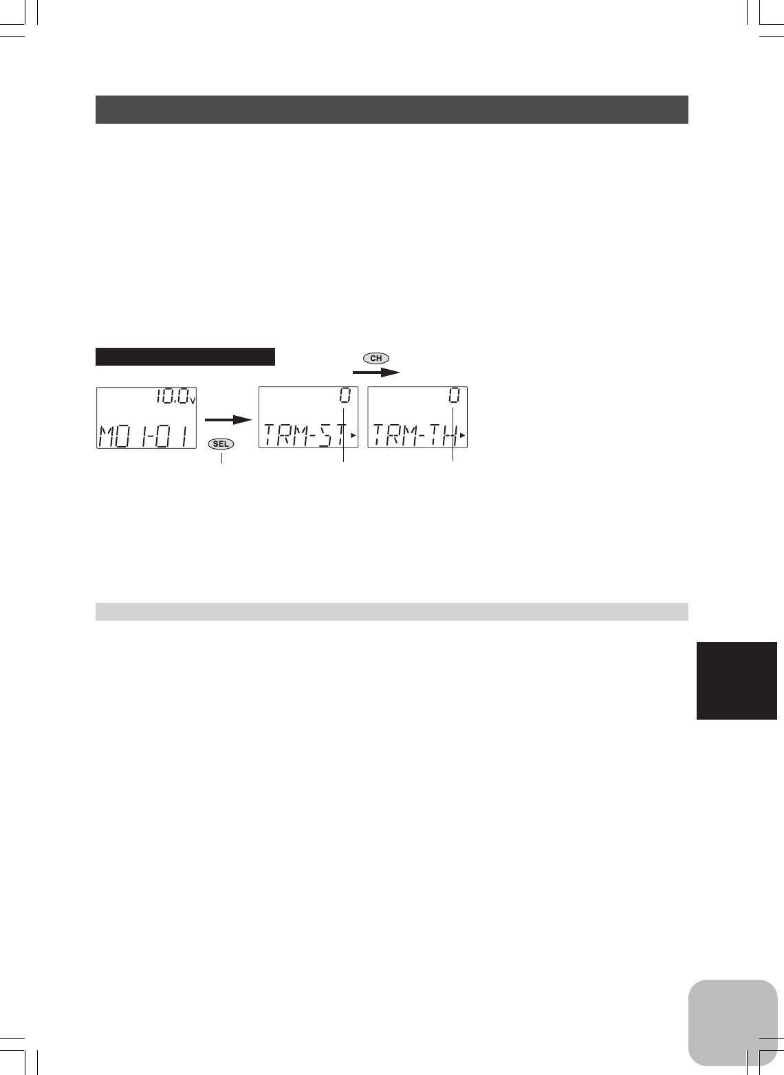
Steering Trim, Throttle Trim / TRM
Steering neutral adjustments and throttle neutral adjustments during a run can be made by
moving the trim lever to the left or right (the up or down). This setting is linked to
transmitter digital trim lever DT1 and DT2. When DT1 or DT2 is assigned to another
function, set the trim function with this screen.
When Trim usage is extreme
If it takes most of your trim movement to get a servo to the neutral position, reposition
the servo horn or servo saver on the servo and inspect your linkage installation.
(Initial screen)
Press "SEL" key to select the
desired function screen.
Calling the setup screen
(Setup screen)
Press "CH" key to select the next set-
up screen.
When each digital trim is operated, the
"TRM" screen is displayed
automaticaly for about three seconds.
Steering trim
position
Throttle trim
position
Adjustment buttons
- Use the (+) and (-) buttons to make
adjustments.
- Press the (+) and (-) buttons simulta-
neously (approx. 1 sec) to return to
the initial screen.
Trim position
L.F.U 100% ~ 0 ~ R.B.D 100%
Initial value: 0%
Setup Item
TRM-ST: Steering trim posiion
TRM-TH: Throttle trim posiion
Trim adjustment
(Preparation)
- Select the desired setup item and make the following adjustments.
1 (Position adjustment)
Use the (+) and (-) buttons to adjust the trim position.
- This position is linked with the digital trim (DT1 or DT2).
2 When ending adjustment, return to the initial screen by pressing the (SEL)
button.
44
Functions
(Initial screen)
Press "SEL" key to select the
desired function screen.
Calling the setup screen
(Setup screen)
When Dual Rate lever is operated, the
"D/R-ST" screen is displayed
automaticaly for about three seconds.
Dual Rate value
D/R value
0 ~ 100%
Initial value: 100%
Setup Item
D/R: Steering D/R value
Steering D/R adjustment
1 (D/R value adjustment)
Use the (+) and (-) buttons to adjust the D/R value.
- This position is linked with the digital trim (DT3).
2 When ending adjustment, return to the initial screen by pressing the (SEL)
button.
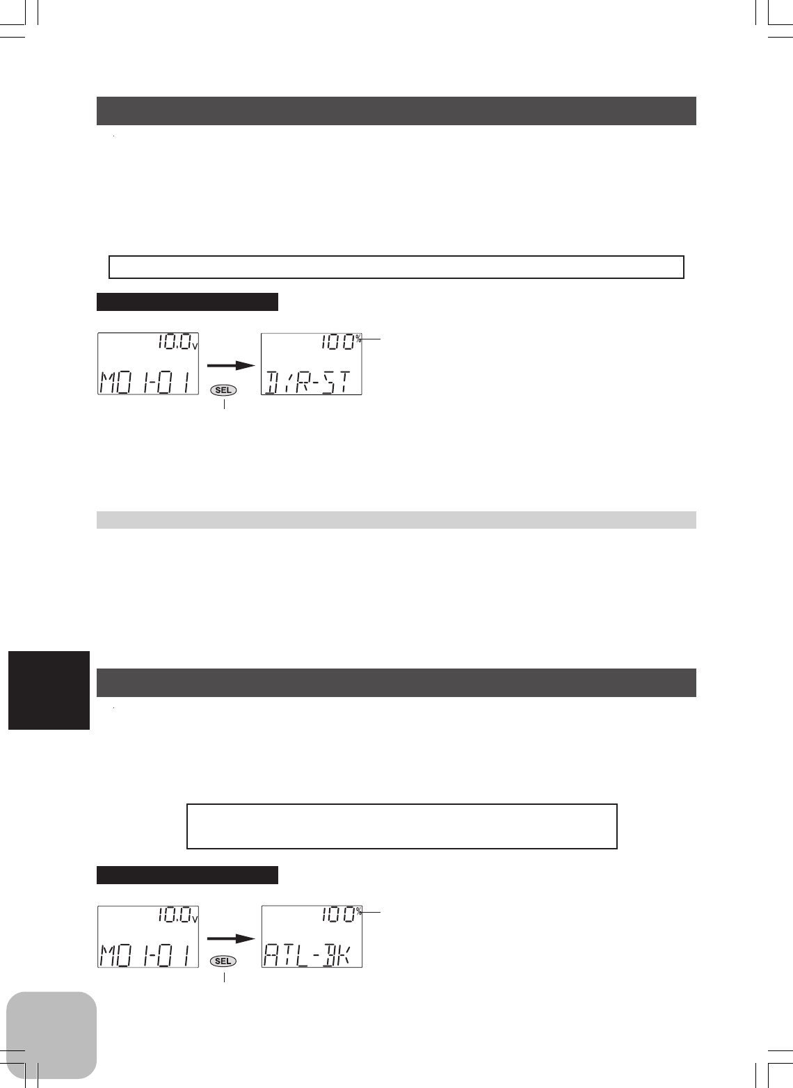
Steering Dual Rate / D/R-ST
When the steering angle is too small at under steering at corners while running, in-
crease the rate. When the steering angle is too large at over steering, decrease the rate.
The setup here is linked with transmitter digital trim DT3. Adjustments can be made
at this screen even if DT3 is assigned to another function.
Operation
- The steering servo left and right steering angles are adjusted simultaneously.
Adjustment buttons
- Use the (+) and (-) buttons to make
adjustments.
- Press the (+) and (-) buttons simulta-
neously (approx. 1 sec) to return to the
initial screen.
Throttle ATL Function / ATL-BK
This function adjusts the - side when the braking effect is strong and the + side when
the braking effect is weak. This setting is linked to transmitter digital trim DT4.
When DT4 is assigned to another function, set the ATL function with this screen.
Operation
The throttle brake side (when the throttle stick is pulled)
brake amount can be adjusted.
(Initial screen)
Press "SEL" key to select the
desired function screen.
Calling the setup screen
(Setup screen)
When ATL lever is operated, the "ATL-
BK" screen is displayed automaticaly
for about three seconds.
ATL position
45
Functions
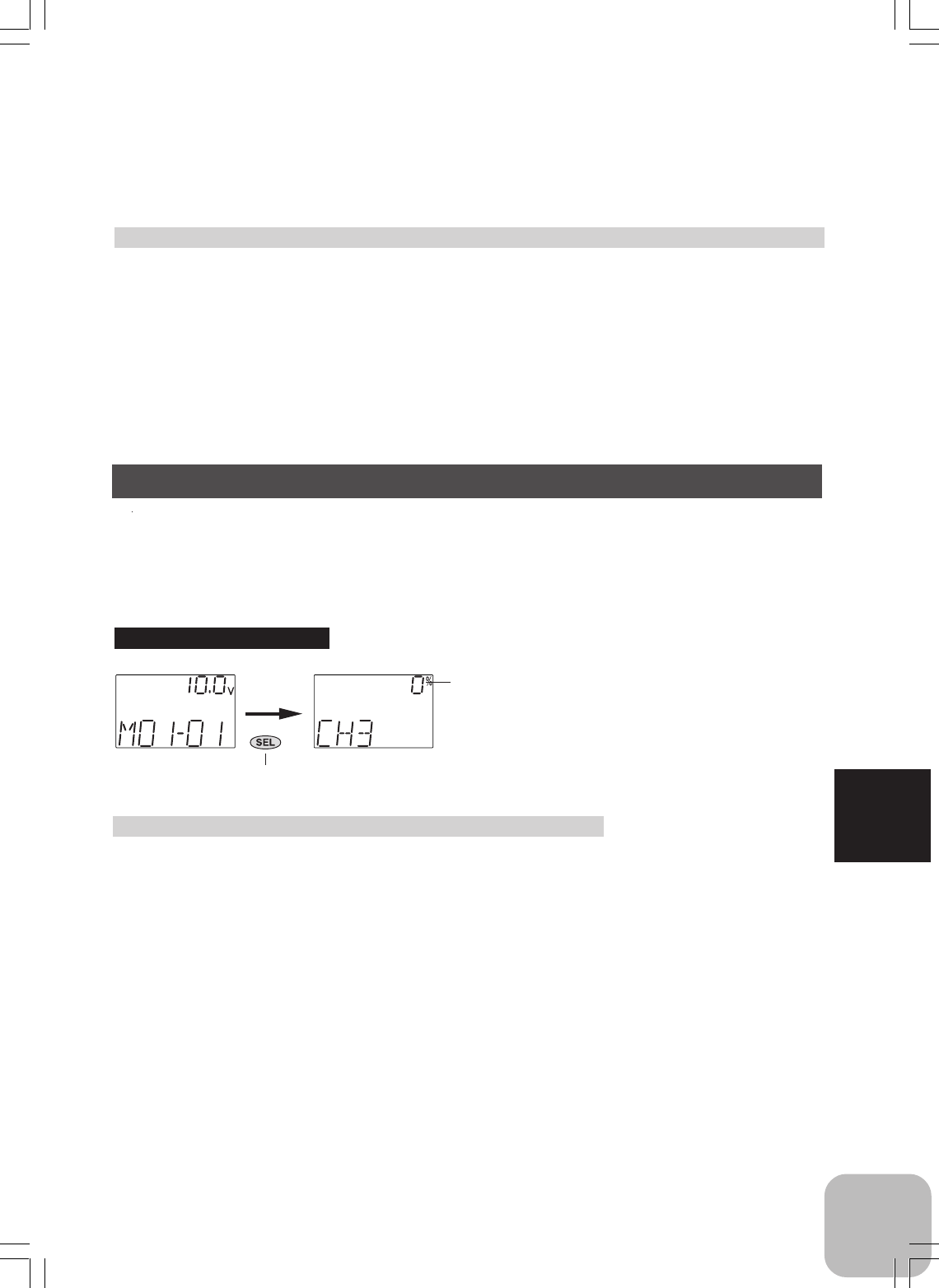
Channel 3 Position / CH3
Use this function to set the servo position of the channel 3.
This setting is linked to transmitter switch (SW2). When the switch is assigned to
another function, set the channel 3 position with this screen.
Adjustment buttons
- Use the (+) and (-) buttons to make
adjustments.
- Press the (+) and (-) buttons simulta-
neously (approx. 1 sec) to return to
the initial screen.
(Initial screen)
Press "SEL" key to select the
desired function screen.
Calling the setup screen
(Setup screen)
When channel 3 switch is operated,
the "CH3" screen is displayed
automaticaly for about three seconds.
Channel 3
position
Channel 3 position
L.F.U 100% ~ 0 ~ R.B.D 100%
Initial value: 0%
Setup Item
RATE: Channel 3 posiion
Channel 3 adjustment
(Preparation)
- Select setup item "CH3" and make the following ad-
justments.
1 (Position adjustment)
Use the (+) and (-) buttons to adjust the channel
3 position.
- This position is linked with the switch (SW2).
2 When ending adjustment, return to the initial
screen by pressing the (SEL) button.
ATL position
0 ~ 100%
Initial value: 100%
Setup Item
ATL-BK: Throttle ATL position
Throttle ATL adjustment
1 (ATL position adjustment)
Use the (+) and (-) buttons to adjust the ATL position.
- This position is linked with the grip lever (DT4).
2 When ending adjustment, return to the initial screen by pressing the (SEL)
button.
Adjustment buttons
- Use the (+) and (-) buttons to make
adjustments.
- Press the (+) and (-) buttons simulta-
neously (approx. 1 sec) to return to the
initial screen.
46
Functions
センターを出すため
に使用する
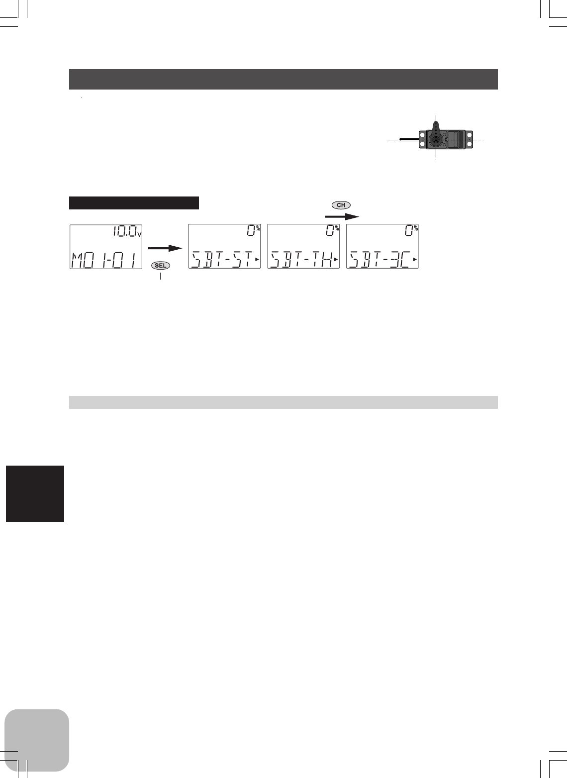
Subtrim / SBT
Use this function to adjust the neutral position of the steer-
ing, throttle and channel 3 servos.
Subtrim shifts the entire servo travel range in the set direc-
tion.
Use to adjust the neutral position
Subtrim adjustment
(Preparation)
-Set the steering and throttle digital trims to the neutral "0" position. Set CH3 to the
center "0" position.
- Preselect setup channel "ST", "TH", or "3C".
1 (Subtrim adjustment)
Use the (+) or (-) button to adjust the center.
(Each channel can be set similarly.)
2 When ending adjustment, return to the initial screen by pressing the (SEL)
button.
(Initial screen)
Press "SEL" key to select the
desired function screen.
Calling the setup screen
(Setup screen)
Press "CH" key to select the next set-
up screen.
Setup Item
SBT-ST : Steering
SBT-TH : Throttle
SBT-3C : Channel 3
Subtrim position
L.F.U 100% ~ 0 ~ R.B.D 100%
Initial value: 0%
Adjustment buttons
- Use the (+) and (-) buttons to make
adjustments.
- Press the (+) and (-) buttons simulta-
neously (approx. 1 sec) to return to
the initial screen.
47
Functions
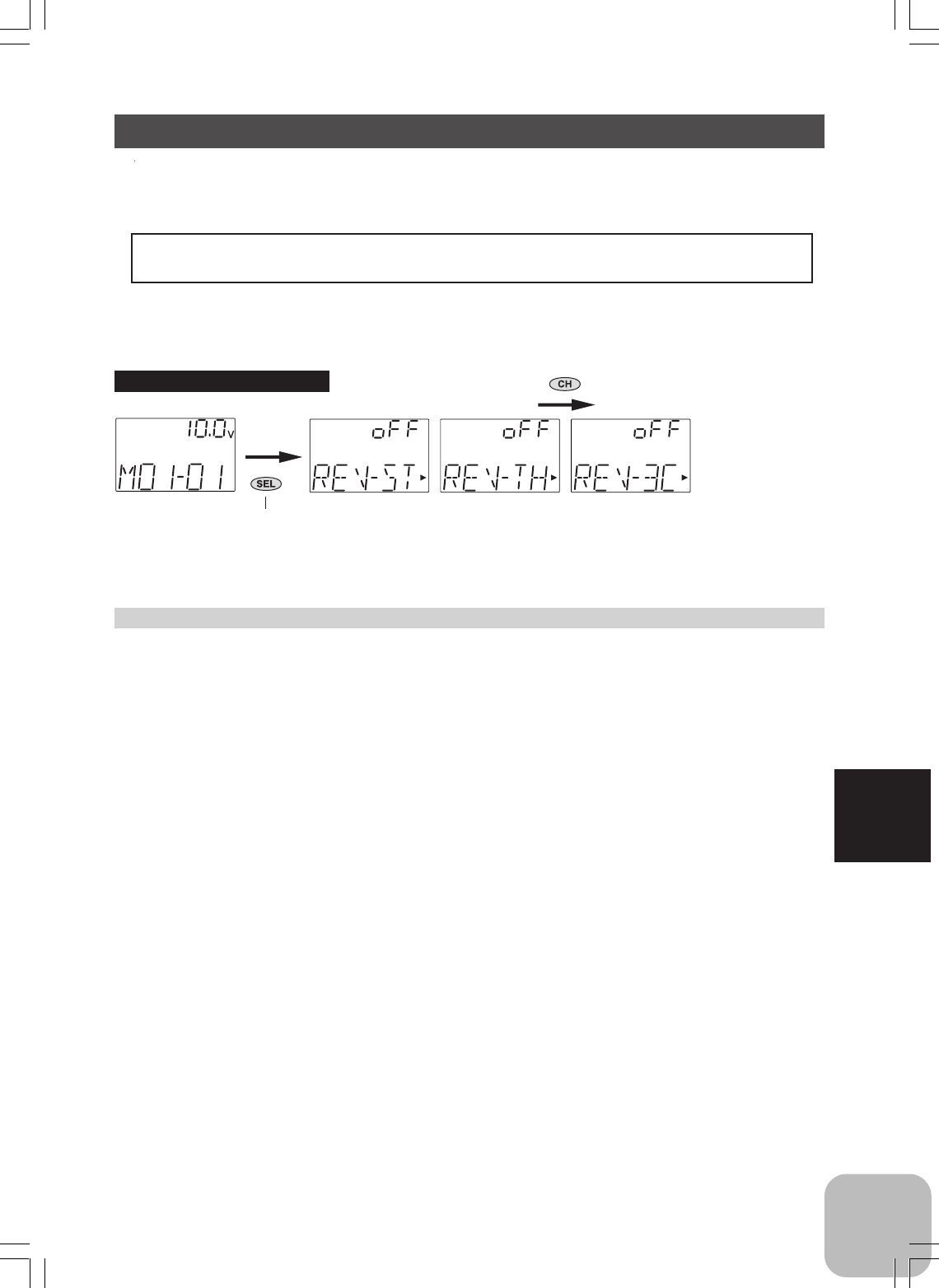
Servo Reverse / REV
This function reverses the direction of operation of the servos related to transmitter
steering, throttle, and channel 3 operation.
However, when the position set by trim or subtrim shifts from the center, the center
becomes the opposite side.
Servo Reverse Function Setting
(Preparation)
- Preselect setup channel "ST", "TH", or "3C".
1 (Servo reverse setting)
Use the (+) or (-) button to reverse the servo operation direction.
(Each channel can be set similarly.)
2 When ending adjustment, return to the initial screen by pressing the (SEL)
button.
(Initial screen)
Press "SEL" key to select the
desired function screen.
Calling the setup screen
(Setup screen)
Press "CH" key to select the next set-
up screen.
Setup Item
REV-ST : Steering
REV-TH : Throttle
REV-3C : Channel 3
Servo direction
OFF: Normal side
ON: Reverse side
48
Functions
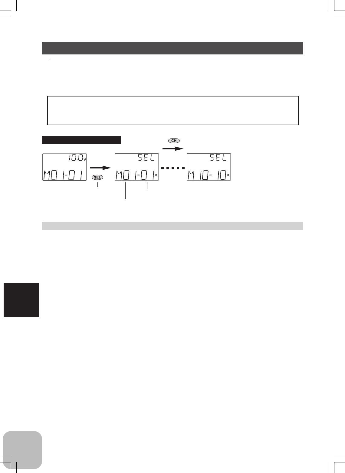
Model Select / SEL
Use this function to call a new model number, or to change a set model number, to set
new model data.The T3GR-2.4G transmitter can store the model data for ten R/C
cars.
Calling model memories of different modulation modes (HRS, PPM)
After the new model is called, signals are still output in the old model modulation
mode until the transmitter power is turned off. Before using the new modulation
mode, turn the power off and on. (See page 53 for the HRS/PPM mode selection.)
Model Select
1 (Model No. selection)
Use the (CH) button to select the Model No.
2 (Select execution)
Press the (+) and (-) buttons simultaneously for about 1 second.
3 When ending adjustment, return to the initial screen by pressing the (SEL)
button.
(Initial screen)
Press "SEL" key to select the
desired function screen.
Calling the setup screen
(Setup screen)
Press "CH" key to select the next set-
up screen.
Model name
Model number:
01 ~ 10
49
Functions
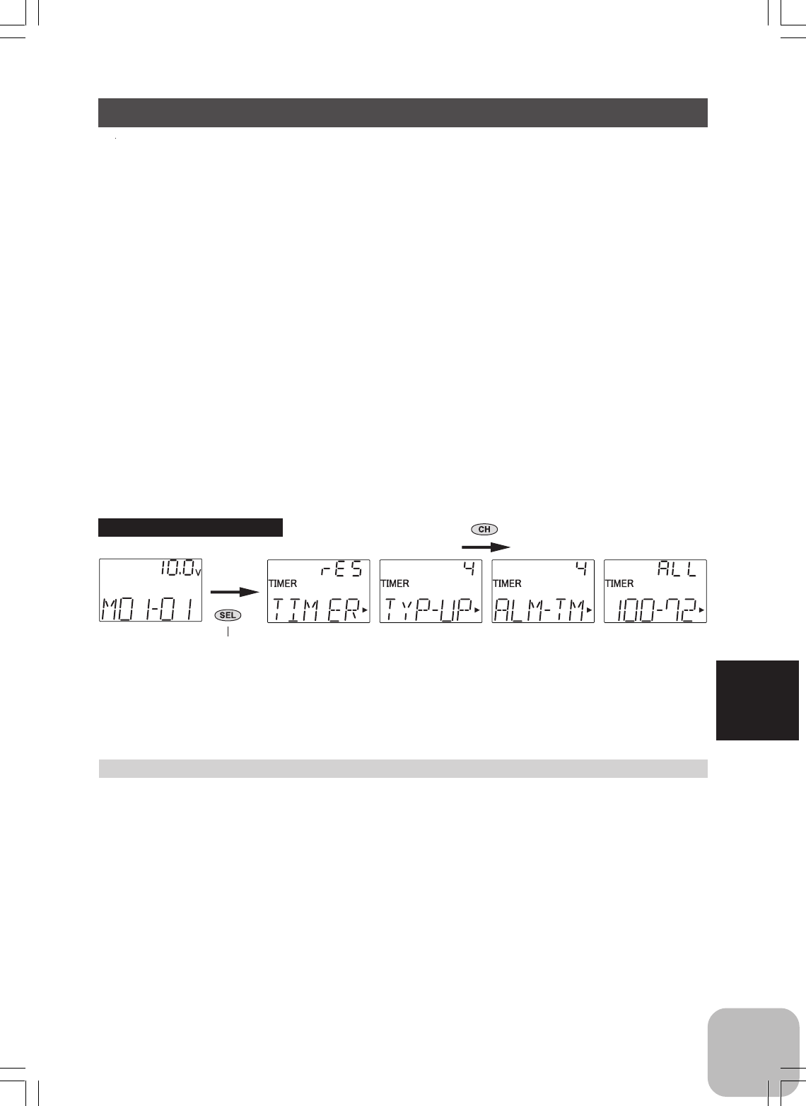
Timer / TIMER
Use the timer by selecting from UP Timer or DOWN timer.
UP TIMER function
- The UP TIMER can be used to count the time between start and stop.
- The timer repeatedly starts and stops each time the switch is operated and
accumulates the time between each start and stop.
- The first start operation can be linked to the throttle stick.
- An alarm sound can be set.
DOWN TIMER function
- The DOWN TIMER can be used to count the time between start and stop. (The
time remaining is displayed.)
- Start and stop are repeated at each switch operation and the time between each start
and stop is counted down and displayed. The start time becomes the alarm set time.
(When the count reaches 00 minute 00 second, the down timer operates like an up
timer.)
- The first start operation can linked with the throttle trigger.
- An alarm sound can be set.
(Initial screen)
Press "SEL" key to select the
desired function screen.
Calling the setup screen
(Setup screen)
Press "CH" key to select the next set-
up screen.
Setup items
TYP: Timer selection
ALM-TM: Alarm time setup
Timer setup
(Preparation)
- Use the function select switch function (page 54) to select the switch.
(SW1: Select the "TM" in the above function.)
1 (Timer selection)
Select setup item "TYP" and use the (+) and (-) buttons to select the timer
type.
2 (Alarm time setup)
Select setup item "ALM-TM" and use the (+) and (-) buttons to set the
alarm time.
Timer type
TYP-UP: UP timer
TYP-DN: DOWN timer
Alarm time
1 ~ 100 min.
Initial value: 4 min.

50
Functions
Checking the lap times
1 Select the lap time screen "ALL" and check the total time.
2 Use the (+) and (-) buttons to scroll each lap screen and check each lap
time.
3 (Linking start with the throttle stick)
Select setup item "TIMER" and press the (+) and (-) buttons simulta-
neously for about 1 second. A beeping sound is generated and "RDY"
displays at the timer display and the system enters the RDY state. Stick
operation starts the timer.
(Timer start/stop operation)
The switch SW1 preset by function select switch function (page 54) starts the timer.
Only starting can be linked with the throttle stick.
(LAP memory operation)
This timer can memorize each lap time of each switch (SW1) operation. (100 laps)
Switch operation after the set time by alarm has elapsed automatically stops the
timer. Each lap time is memorized in a lap memory. The lap times are written sequen-
tially. When the timer is stopped, the final lap is memorized and the total time is
automatically written. The lap times are memorized to a next start and can be checked
at the lap time screen.
51
Functions
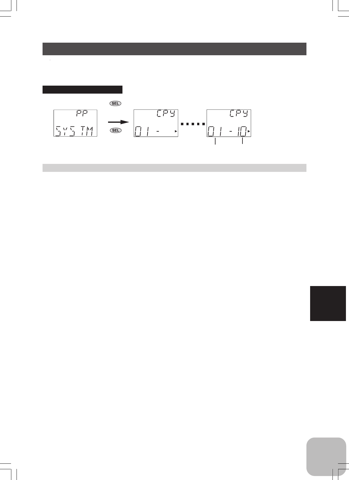
Model Copy
1 (Copy destination selection)
Use the (CH) button to select the copy destination model No.
2 (Copy execution)
Press the (+) and (-) buttons simultaneously for about 1 second.
3 When ending adjustment, turn off the power switch before use.
Model Copy / CPY
This function copies the entire contents of the currently called model memory to
another model memory.
Current model No. Copy destination model No.
Calling the setup screen
1. Turn on the power switch
while pressing "SEL" key.
2. Next, use "SEL" key to select
the desired function screen.
52
Functions
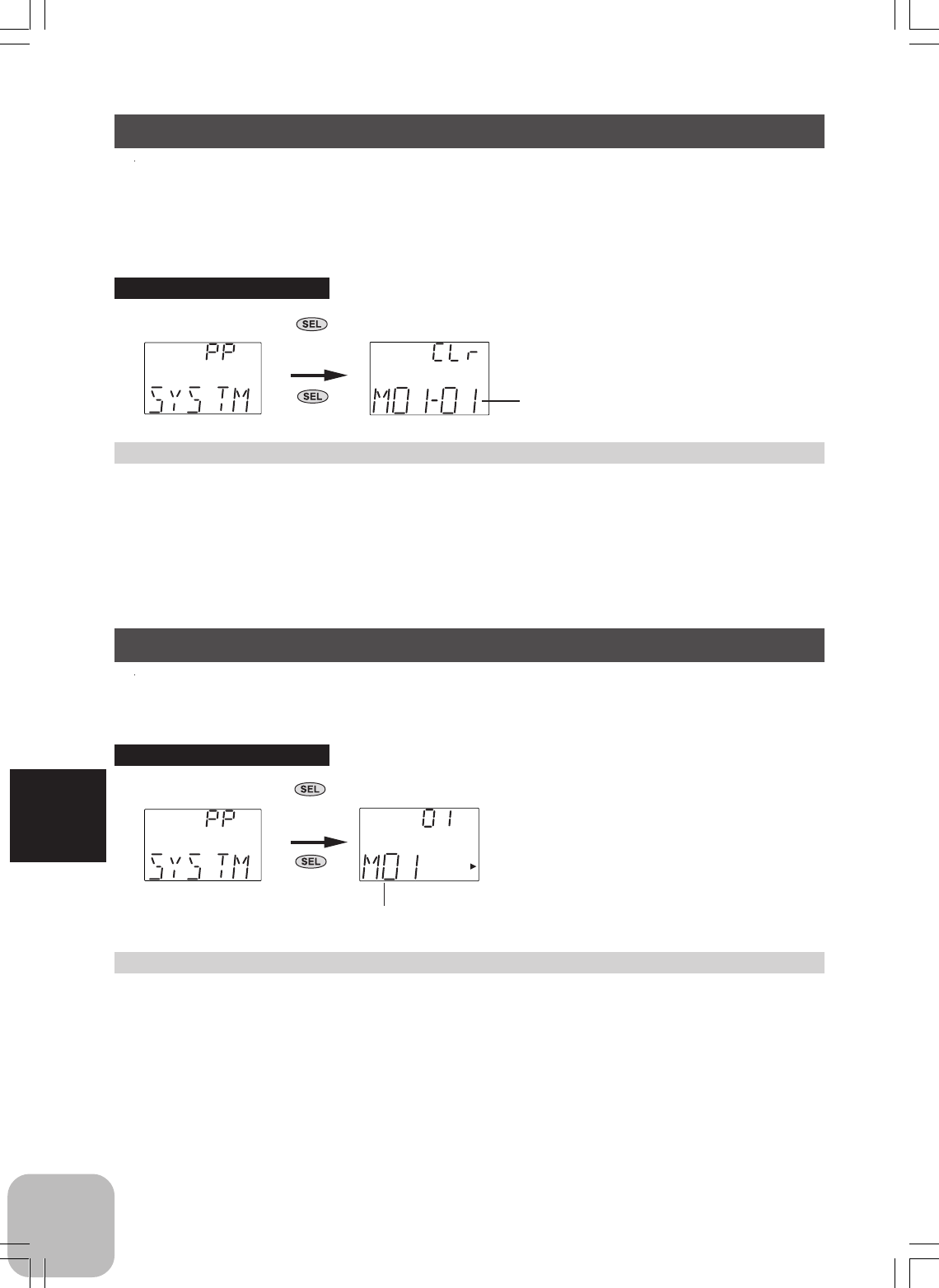
Model Reset / CLR
This functions resets the contents of the currently called model memory to the initial
value. However, it does not reset the lap time memory, HRS/PPM select, and LED
mode selection.
Model Reset
1 (Reset execution)
Press the (+) and (-) buttons simultaneously for about 1 second.
2 When ending adjustment, turn off the power switch once before use.
Current model No.
Calling the setup screen
1. Turn on the power switch
while pressing "SEL" key.
2. Next, use "SEL" key to select
the desired function screen.
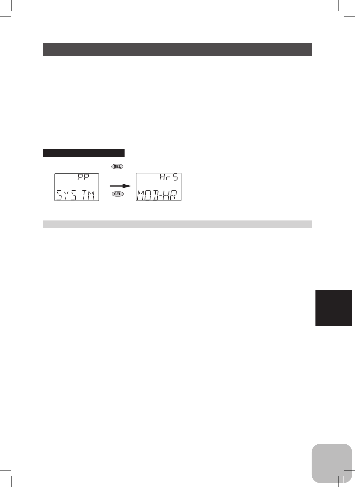
Model Name / NAM
This function allows you to assign a three character name to each model memory.
(Number and alphabet can be used.)
Model Name
1Move the cursor (blinking) to the column you want to change using the
(CH) button.
2 Change the character using the (+) or (-) button.
(Set the model name by repeating steps 1 and 2 above. )
3 When ending adjustment, turn off the power switch before use.
Model name
Calling the setup screen
1. Turn on the power switch
while pressing "SEL" key.
2. Next, use "SEL" key to select
the desired function screen.
53
Functions
HRS/PPM mode selection
1 (Mode selection)
Use the (+) or (-) button to select the mode.
2 When ending adjustment, turn off the power switch before use.
HRS/PPM Select / MOD
The signal mode output from the transmitter can be changed. (PPM/HRS)
- When the mode was changed and when a model of a different mode was
selected, signals are output in the mode set at the point at which the
transmitter power was turned back on.
Signal mode
HR: HRS mode
PP: PPM mode
Calling the setup screen
1. Turn on the power switch
while pressing "SEL" key.
2. Next, use "SEL" key to select
the desired function screen.
54
Functions
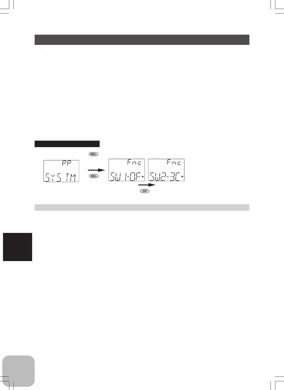
Function Select Switch / FNC-SW
This function allows selection of the function to be performed by the switches
(SW1/SW2).
Settable functions (SW1)
OF: (function off)
3C: Channel 3
MX: Programmable mixing
TM: Timer switch
Settable functions (SW2)
OF: (function off)
3C: Channel 3
MX: Programmable mixing
Function select switch setup
1 (Setup item selection)
Use the (CH) button to select the item to be set.
2 (When changing the function)
Use the (+) or (-) button to select the function.
3 When ending adjustment, turn off the power switch before use.
Calling the setup screen
1. Turn on the power switch
while pressing "SEL" key.
2. Next, use "SEL" key to select
the desired function screen.
Press "CH" key to select the next set-
up screen.
55
Functions
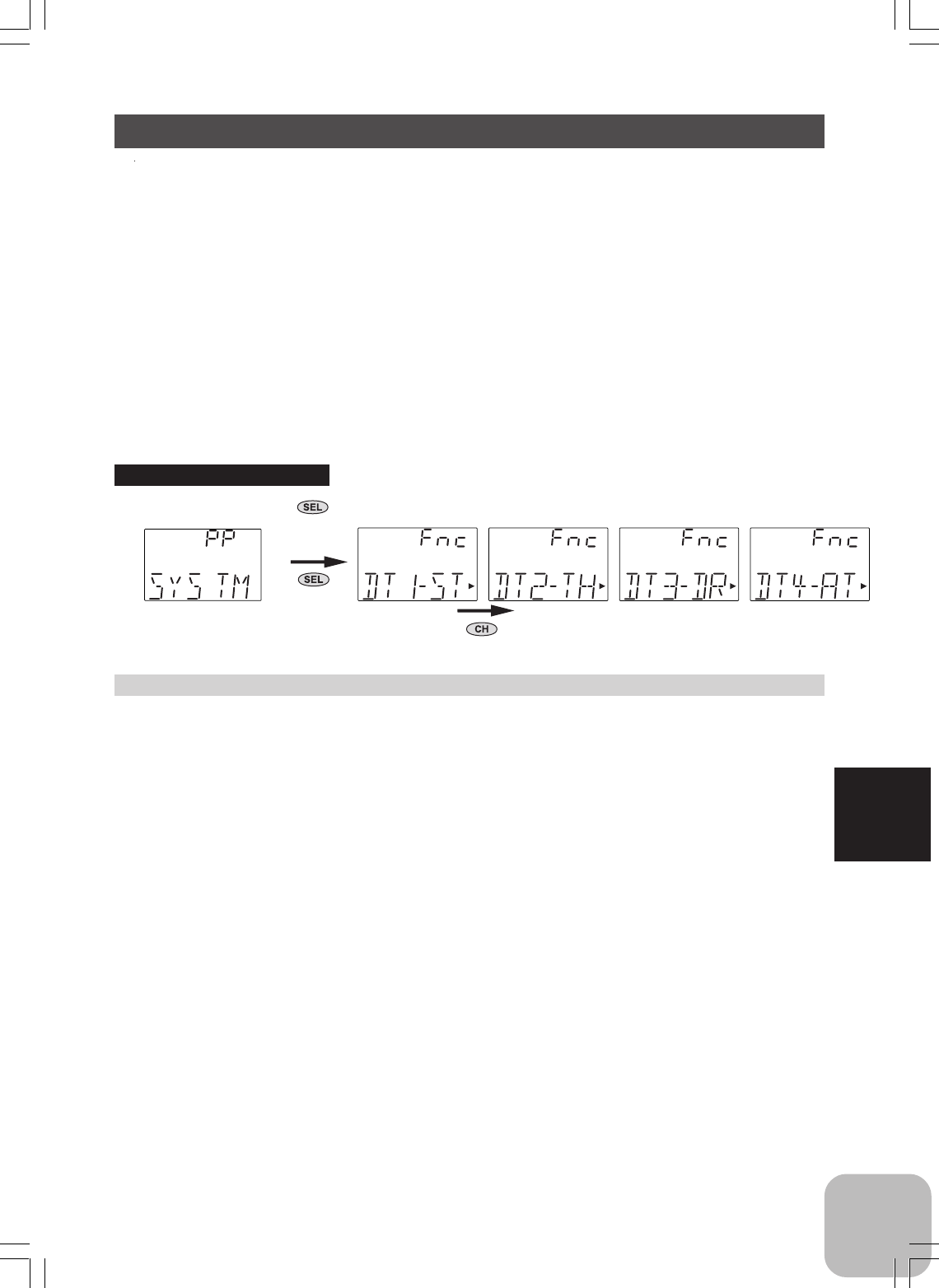
Initially set functions
DT1: Steering trim
DT2: Throttle trim
DT3: Dual rate function
DT4: ATL function
Function Select Lever / FNC-DT
This function allows selection of the function performed by digital trim (DT1/DT2/
DT3/DT4).
Settable functions
ST: Steering trim
TH: Throttle trim
DR: Steering D/R
AT: Throttle ATL
E1: Steering EXP
BK: Brake mixing rate
3C: Channel 3
OF: (function off)
Function select lever setup
1 (Setup item selection)
Use the (CH) button to select the item to be set.
2 (When changing the function)
Use the (+) or (-) button to select the function.
3 When ending adjustment, turn off the power switch before use.
Calling the setup screen
1. Turn on the power switch
while pressing "SEL" key.
2. Next, use "SEL" key to select
the desired function screen.
Press "CH" key to select the next set-
up screen.
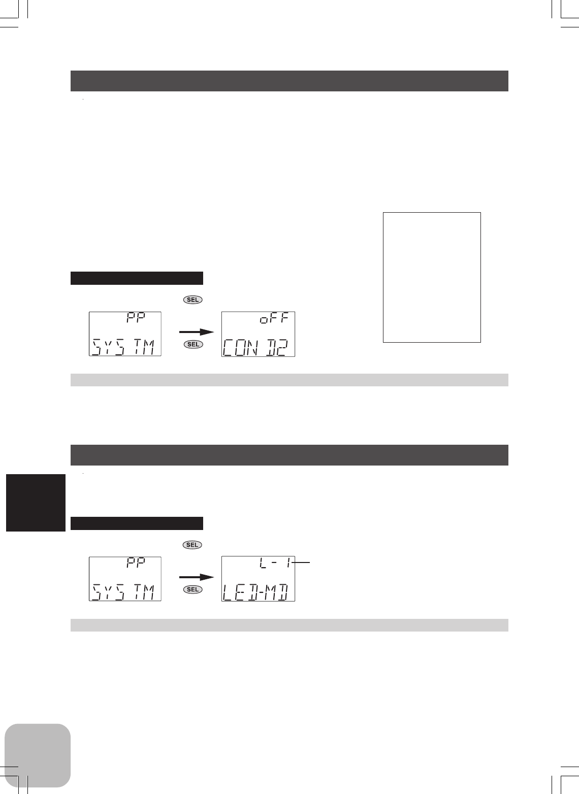
56
Functions
Condition 2 Selection / COND2
Condition 2 selection
1 Use the (+) or (-) buttons to select the on/off state.
2 When ending selection, turn off the power switch before use.
Calling the setup screen
1. Turn on the power switch
while pressing "SEL" key.
2. Next, use "SEL" key to select
the desired function screen.
Condition 2 Selection
In specific functions, two rates can be set up, and switched with the switch (SW1)
simultaneously during a run.
If this function is activated, SW1 is used only for this function, and it becomes impos-
sible to use it for other functions automatically.
When the switch (SW1) is operated, Condition 2 on/off state changes by turn. When
this function is turned on, the beep sounds and the pilot lamp blinks.
Related functions:
Steering speed
Steering EXP
Throttle EXP
ABS return amount
Brake mixing rate
Programmable mixing
Steering trim
Throttle trim
Steering D/R
Throttle ATL
LED Mode Selection / LED-MD
You can select your desired brightness of the pilot lamp. (Four steps)
LED mode selection
1 Use the (+) or (-) buttons to select the brightness of the pilot lamp.
2 When ending selection, turn off the power switch once before use.
Calling the setup screen
1. Turn on the power switch
while pressing "SEL" key.
2. Next, use "SEL" key to select
the desired function screen.
LED mode
(Min.)L-1 ~ L-4(Max.)
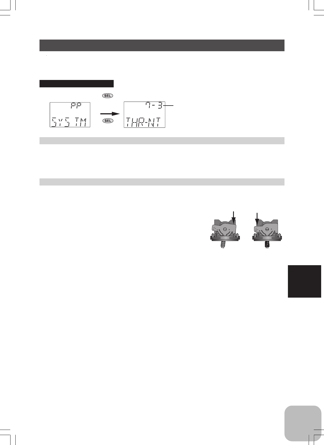
57
Functions
Throttle Neutral Adjuster / THR-NT
You can select your desired throttle neutral position. (7:3 or 5:5)
Neutral position selection
1 Use the (+) or (-) buttons to select the neutral position. ("7-3" or "5-5")
2 When ending selection, once turn off the power switch before use.
Calling the setup screen
1. Turn on the power switch
while pressing "SEL" key.
2. Next, use "SEL" key to select
the desired function screen.
Neutral position
"7-3": 7:3
"5-5": 5:5
Stick lever adjustment
- Always adjust the throttle stick lever position according to the above settings.
1 Remove the four transmitter rear case screws and remove the rear case.
2 Adjust the neutral position of the throttle stick ac-
cording to the above neutral position selection by
pressing the throttle stick in the arrow direction.
*Press it downward fully and firmly.
3 Close the rear case and tighten the four screws.
7:3 5:5
58
Reference
Reference
Ratings
*Specifications and ratings are subject to change without prior notice.
- Communication method: One-way operation system
- Mode: PPM, HRS (Auto-detect)
- Maximum operating range: 80m (Optimum condition)
- For safety: F/S, B-F/S, ID (About 4 billion ways of pair identifications)
Transmitter T3GR-2.4G:
(2 stick system, 3 channels)
- Transmitting frequency: 2.4GHz band
- Power requirement: (NiCd battery) NT8F700B(9.6V),
(Dry cell battery) Penlight x 8(12V)
- Current drain: 250mA or less
- Transmission antenna: 1/2 mono-pole
Receiver R603FF:
- Power requirement: 6V NiCd battery
- DSC function available
- RS232C port: (for factory use only)
- Size: 39x26x14mm (excluding a projection part)
- Weight: 14.1g
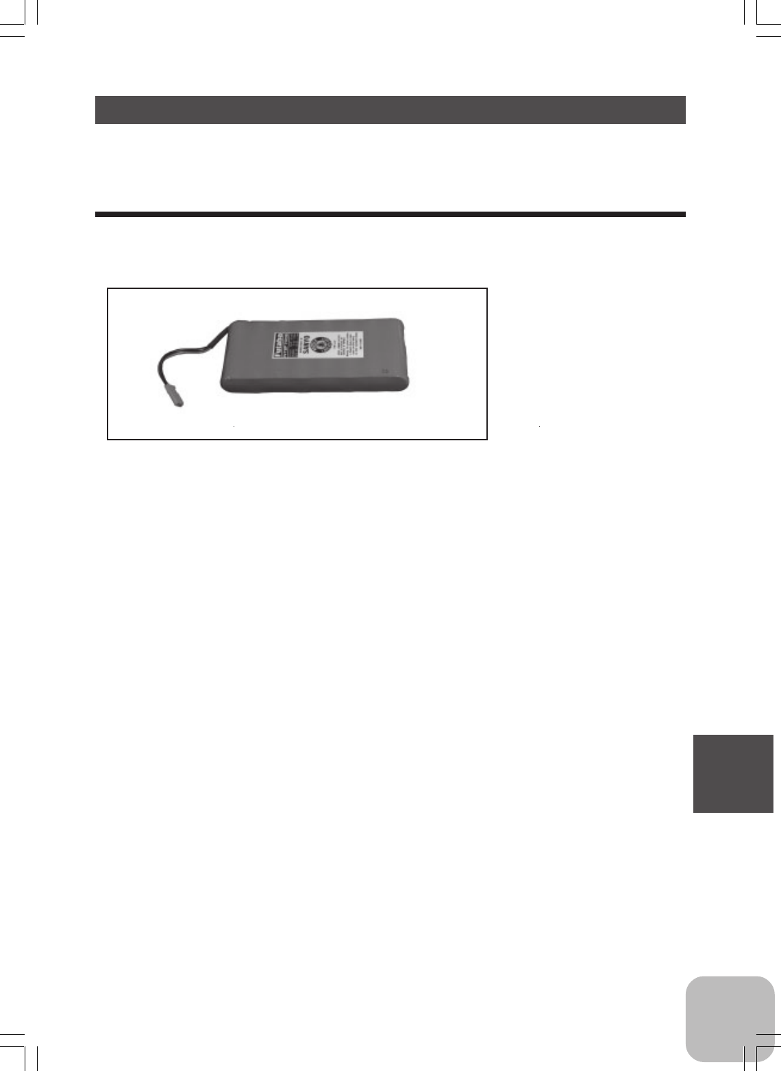
59
Reference
Optional Parts
The following parts are available as 3GR-2.4G system options. Purchase them to
match your application. For other optional parts, refer to our catalog.
Transmitter NiCd Battery
When purchasing a transmitter NiCd battery as a spare, etc., use the following:
NT8F700B
(9.6V/700mAh)
Part name

60
Reference
Troubleshooting
If your system fails to operate or you experience a short range problem or erratic
control, check the table below for possible causes. If after you have followed the
suggestions listed the problem is not corrected, return the system to our service de-
partment for inspection and repair.
(Item Check)
Transmitter
Battery
Dead battery -> Change the batteries. Charge the NiCd
Batteries inserted incorrectly. -> Reload the batteries in accordance with the polarity markings
Faulty contact -> Check to see if the contacts are bent and not making good contact
Dirty contacts -> Clean the contacts and check for corrosion.
Monitor LED
Check the LED on the rear of the transmitter.
Refer to the "How to link the transmitter and the receiver", p 23.
Receiver
Battery
Dead battery -> Replace or recharge
Wrong polarity -> Check connections
Antenna
Near other wiring -> Move away from wiring
Was antenna cut -> Request repair
Is the antenna installed correctly -> Refer to the receiver installation, p 21.
Monitor LED
Check the LED of the receiver.
Refer to the "How to link the transmitter and the receiver", p 23.
Connector connections
Wiring incorrect -> Insert all connectors firmly
Loose connections -> Push the connector in firmly
Linkage
Binding or loose -> Adjust the linkage in model
Is movement stiff -> Adjust linkage in model
Motor (Electric powered)
Noise problems -> Install capacitors on motor
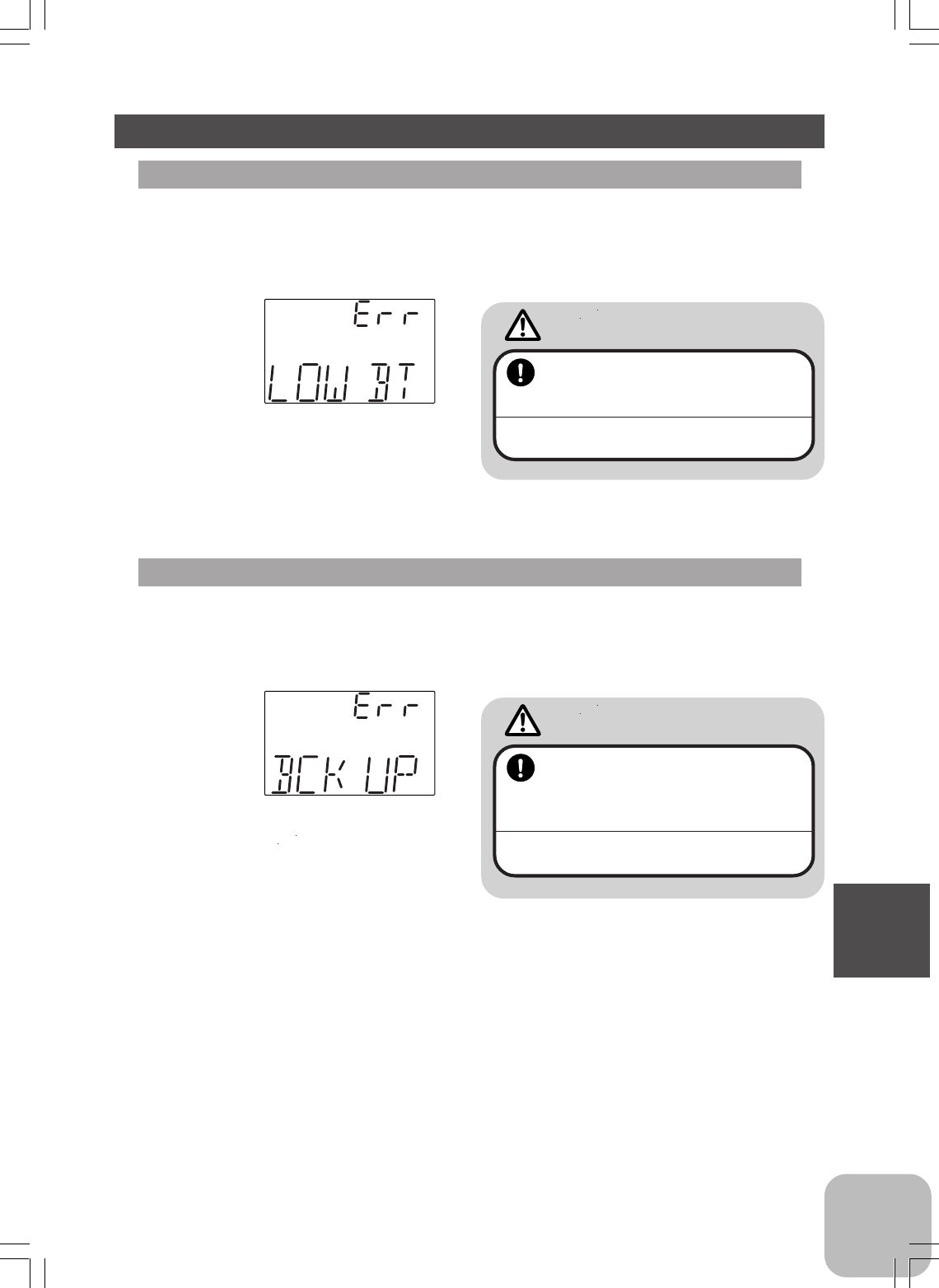
61
Reference
Error Displays
Low Battery Alarm
If the transmitter battery voltage drops to 8.5V or less, an audible alarm will sound
and "LOW BT" will be displayed on the LCD screen.
LCD screen:
Audible alarm:
Continuous tone.
Backup Error
If the data is lost for an unknown reason, an audible alarm will sound and "BCK UP"
will be displayed on the LCD screen.
LCD screen:
Audible alarm:
Tone will sound (9 times), then
repeat.
Warning
When a low battery alarm is gener-
ated, cease operation immediately
and retrieve the model.
If the battery goes dead while in operation, you will
lose control.
Warning
When a backup error is generated,
immediately stop using the system
and request repair from the Futaba
Service Center.
If you continue to use the system, the transmitter
may malfunction and cause loss of control.

62
Reference
When requesting repair
Before requesting repair, read this instruction again and recheck your system. Should
the problems continue, request as follows.
(Information needed for repair)
Describe the problem in as much detail as possible and send the letter along with the
system in question.
- Symptom (Including the conditions and when the problem occurred)
- R/C System (Send transmitter, receiver and servos)
- Model (Type of model, brand name and model number or kit name)
- Detailed packing list (Make a list of all items sent in for repair)
- Your name, address and telephone number.
(Warranty)
Read the Warranty card.
- When requesting warranty service, send the card or some type of dated proof of
purchase.
Hobby Services (U.S. only)
3002 N. Apollo Drive, Suite 1
Champaign, IL 61822 U.S.A.
Phone: (217) 398-0007
service@futaba-rc.com
FUTABA CORPORATION
Makuhari Techno Garden Bldg., B6F 1-3 Nakase, Mihama-ku, Chiba 261-8555, Japan
Phone: (043) 296-5119 Facsimile: (043) 296-5124
©FUTABA CORPORATION 2007, 3 (1)
INSTRUCTIONS MANUAL
FEDERAL COMMUNICATIONS COMMISSION
INTERFERENCE STATEMENT
This equipment has been tested and found to comply with the limits for a Class B digital
device, pursuant to Part 15 of the FCC Rules. These limits are designed to provide
reasonable protection against harmful interference in a residential installation. This
equipment generates, uses, and can radiate radio frequency energy and, if not installed
and used according to the instructions, may cause harmful interference to radio
communications. However, there is no guarantee that interference will not occur in a
particular installation. If this equipment does cause harmful interference to radio or
television reception, which it found by turning the equipment off and on, the user is
encouraged to try to correct the interference by one or more of the following measures:
-- Reorient or relocate the receiving antenna.
-- Increase the separation between the equipment and receiver.
-- Connect the equipment into an outlet other than the receiver’s
-- Consult the dealer or an experienced radio/TV technician for assistance.
CAUTION:
To assure continued FCC compliance:
(1) Any changes or modifications not expressly approved by the grantee of this device
could void the user's authority to operate the equipment.
FCC Label Compliance Statement:
This device complies with Part 15 of the FCC Rules. Operation is subject to the
following two conditions: (1) this device may not cause harmful interference, and (2)
this device must accept any interference received, including interference that may
cause undesired operation.
Exposure to Radio Frequency Radiation
To comply with FCC RF exposure compliance requirements, a separation distance of at
least 20cm must be maintained between the antenna of this device and all persons. This
device must not be co-located or operating in conjunction with any other antenna or
transmitter.