Futaba T3PM-24G Radio Control(Transmitter) User Manual 2G Manual
Futaba Corporation Radio Control(Transmitter) 2G Manual
Futaba >
Contents
- 1. 2G Manual
- 2. User Manual
2G Manual
• No part of this manual may be reproduced in any form without prior permission.
• The contents of this manual are subject to change without prior notice.
• This manual has been carefully written. Please write to Futaba if you feel that any corrections
or clarications should be made.
Before using your new 3PM 2.4GHz system, please read this manual thoroughly and use
the system properly and safely. After reading this manual, store it in a safe place.
About this guide
This manual is supplement to the separate "3PM INSTRUCTION MANUAL". Refer to
the "3PM INSTRUCTION MANUAL" for the basic operating instructions. In the pro-
gramming mode, refer to the programming instructions of the 3PM-FM system.
This guide describes the new functions and the safety precautions of the 3PM 2.4GHz
system.
1M23N13512
Contents and Technical Specications
Your 3PM 2.4GHz system includes the following components;
Installing the T3PK-2.4G/R603FS
[Specication]
• Communication method: One-way operation system
• Mode: PPM, HRS (Auto-detect)
• Maximum operating range: 80m (Optimum condition)
• For safety: F/S, B-F/S, ID (About 4billion ways of pair identications)
Transmitter T3PM-2.4G;
(Wheel system, 3 channels)
• Transmitting frequency: 2.4GHz band
• Power requirement: (NiCd battery) NT8F700B(9.6V), (Dry cell battery)
Penlight x 8(12V)
• Current drain: 250mA or less
• Transmission antenna: 1/2λ mono-pole
Receiver R603FS;
• Reception antenna: Diversity type (Two antennas: internal and external)
• Power requirement: 6V Nicd battery
• DSC function available
• RS232C port: (for factory use only)
• Size: 39x26x14mm (excluding a projection part)
• Weight: 14.1g
3PM 2.4GHz
System
Thank you for purchasing a 3PM 2.4GHz system. This system is based on the combination of
the newly developed 2.4GHz transmitter and its correspondent receiver. The system utilizes
the 2.4GHz-SS radio communication and an ultra small antenna. In addition, the system
inherits Futaba's unique HRS (High Response System).
Features
2.4GHzSS (Spread Spectrum) radio communication system
Frequency channel setting unnecessary: Sifting the channels within the 2.4GHz band
automatically, this system minimizes the interference from other 2.4GHz system.
Accepts no unwanted signals by using ID code
The function “Auto-Detect” is utilized to automatically determine which mode is active,
HRS or PPM mode. (R603FS)
Short and small antenna (T3PK-2.4G)/Diversity antenna (R603FS)
•
•
•
•
•
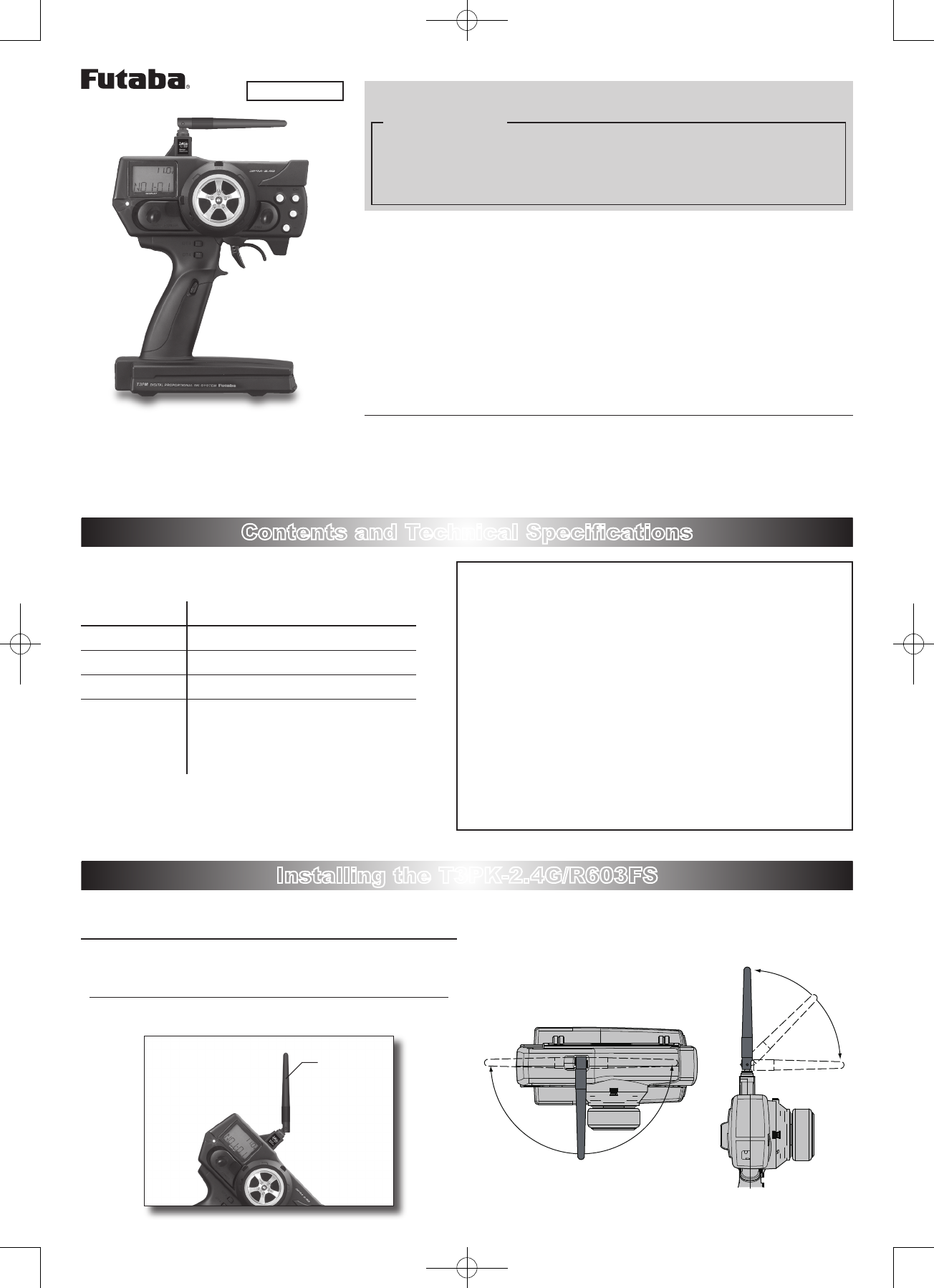
Install and adjust the T3PK-2.4G transmitter and R603FS receiver as described below.
Adjustment of the antenna direction
WARNING
Adjust the antenna vertically to the ground. Otherwise, the oper-
ating range may become shorter.
Antenna
(Antenna Moving Range)
INSTRUCTION MANUAL
For cars only
3PM 2.4GHz system
Transmitter T3PM-2.4G
Receiver R603FS
Servo --------
Miscellaneous
Transmitter battery holder
Receiver switch
Mini screwdriver
Instruction manual
Usage Precaution
WARNING
Special attention should be paid before turning on the system
while other cars are running or other airplanes are flying be-
cause the 2.4GHz RC system could potentially affect them.
WARNING
Be sure to set the Fail Safe function.
Repair Service
Before requesting repair, read this instruction manual again and recheck your
system. Should the problem continue, request repair service as follows:
Describe the problem in as much detail as possible and send it with a detailed
packing list together with the parts that require service.
•
Symptom (Including when the problem occurred)
• System(Transmitter, Receiver, Servo's and model numbers)
• Model (Model name)
• Model Numbers and Quantity
• Your Name, Address, and Telephone Number.
If you have any questions regarding this product, please consult your local
hobby dealer or contact the Futaba Service Center.
FUTABA CORPORATION Phone: (043) 296-5118 Facsimile: (043) 296-5124
Makuhari Techno Garden Bldg., B6F 1-3 Nakase, Mihama-ku, Chiba 261-8555, Japan
©FUTABA CORPORATION 2006, 10 (1)
Receiver installation
R603FS Receiver
Antenna
tube
Antenna
Coaxial
cable
R603FS
1 Install the R603FS receiver on the
car as follow;
Note: The operating range may become
shorter, although depending on where
the receiver and the antenna are
mounted.
WARNING
Install the antenna in the higher place as
shown in the figure.
Do not cut the antenna.
Keep the antenna away from the motor,
ESC and other noise sources as pos-
sible as you can.
Put the antenna in the antenna tube to
protect it.
Do not bend the coaxial cable. It causes
damage.
Wrap the receiver with something soft such as foam rubber to
avoid vibration. If there is a chance of getting wet, put the receiv-
er in a waterproof bag or balloon to avoid water.
CAUTION
Always use R603FS under the following conditions;
Power supply; 6V Nicd battery (PPM/HRS mode)
Servo; 6V type Futaba Digital Servo (HRS mode)
*
If the conditions are different, control is impossible or the servo may be damaged.
How to turn on the power
A certain ID number is given to the receiver automatically. Identifying
this ID number, the system will minimize the interference from other
transmitters.
1 Bring the transmitter and the receiver close to each other
within one meter.
2 Turn on the transmitter.
LED and
F/S switch
Note: Check the LED on the rear of the transmitter.
Parameter check for 0.5 seconds after power-on Red: On
Transmitting signals Green: On
F/S is activated by the F/S switch of the transmit-
ter. (PPM mode) Green: Blink
Unrecoverable failure (EEPROM, etc.)
Red and Green turn
on alternatively.
3 Turn on the receiver.
4 Push the tactile switch of the receiver.
Note: Check the LED of the receiver.
No signal reception Red : On
Receiving signals Green: On
Receiving signals, but ID is unmatched. Green: Blink
Unrecoverable failure (EEPROM, etc.) Red and Green turn
on alternatively.
How to Set the F/S Position
PPM mode only:
*HRS mode: Set the F/S function by the fail safe function menu.
1 Move and hold the throttle trigger (stick) to the F/S servo
position where you want to set (slow side) then push the F/S
switch on the transmitter.
The LED blinks green.
Note: Always set again when turning on the power.
Battery F/S function
The Battery F/S function becomes active when the voltage of the
receiver becomes 4.75V or less. The throttle servo move to the preset
F/S position.
Special Markings;
Pay special attention to the safety at
the parts of this manual that are
indicated by the following marks.
[Symbol] ; Prohibited ; Mandatory
Mark Meaning
Procedures which may lead to a dangerous condition and cause
death or serious injury to the user if not carried out properly.
Procedures which may lead to a dangerous condition or cause death
or serious injury to the user if not carried out properly, or procedures
where the probability of superficial injury or physical damage is high.
Procedures where the possibility of serious injury to the user is
small, but there is a danger of injury, or physical damage, if not
carried out properly.
INSTRUCTIONS MANUAL
FEDERAL COMMUNICATIONS COMMISSION
INTERFERENCE STATEMENT
This equipment has been tested and found to comply with the limits for a Class B digital
device, pursuant to Part 15 of the FCC Rules. These limits are designed to provide
reasonable protection against harmful interference in a residential installation. This
equipment generates, uses, and can radiate radio frequency energy and, if not installed
and used according to the instructions, may cause harmful interference to radio
communications. However, there is no guarantee that interference will not occur in a
particular installation. If this equipment does cause harmful interference to radio or
television reception, which it found by turning the equipment off and on, the user is
encouraged to try to correct the interference by one or more of the following measures:
-- Reorient or relocate the receiving antenna.
-- Increase the separation between the equipment and receiver.
-- Connect the equipment into an outlet other than the receiver’s
-- Consult the dealer or an experienced radio/TV technician for assistance.
CAUTION:
To assure continued FCC compliance:
(1) Any changes or modifications not expressly approved by the grantee of this device
could void the user's authority to operate the equipment.
FCC Label Compliance Statement:
This device complies with Part 15 of the FCC Rules. Operation is subject to the
following two conditions: (1) this device may not cause harmful interference, and (2)
this device must accept any interference received, including interference that may
cause undesired operation.
Exposure to Radio Frequency Radiation
To comply with FCC RF exposure compliance requirements, a separation distance of at
least 20cm must be maintained between the antenna of this device and all persons. This
device must not be co-located or operating in conjunction with any other antenna or
transmitter.