Futaba T3PV-24G Radio Control User Manual Rev 02 160525
Futaba Corporation Radio Control Rev 02 160525
UserManual.wiki
>
Futaba
>
T3PV 24G User Manual
User Manual-Rev.02(160525)
Navigation menu
Upload a User Manual
Namespaces
Wiki Guide
HTML
PDF
Info
Views
User Manual
Discussion / Help
Navigation

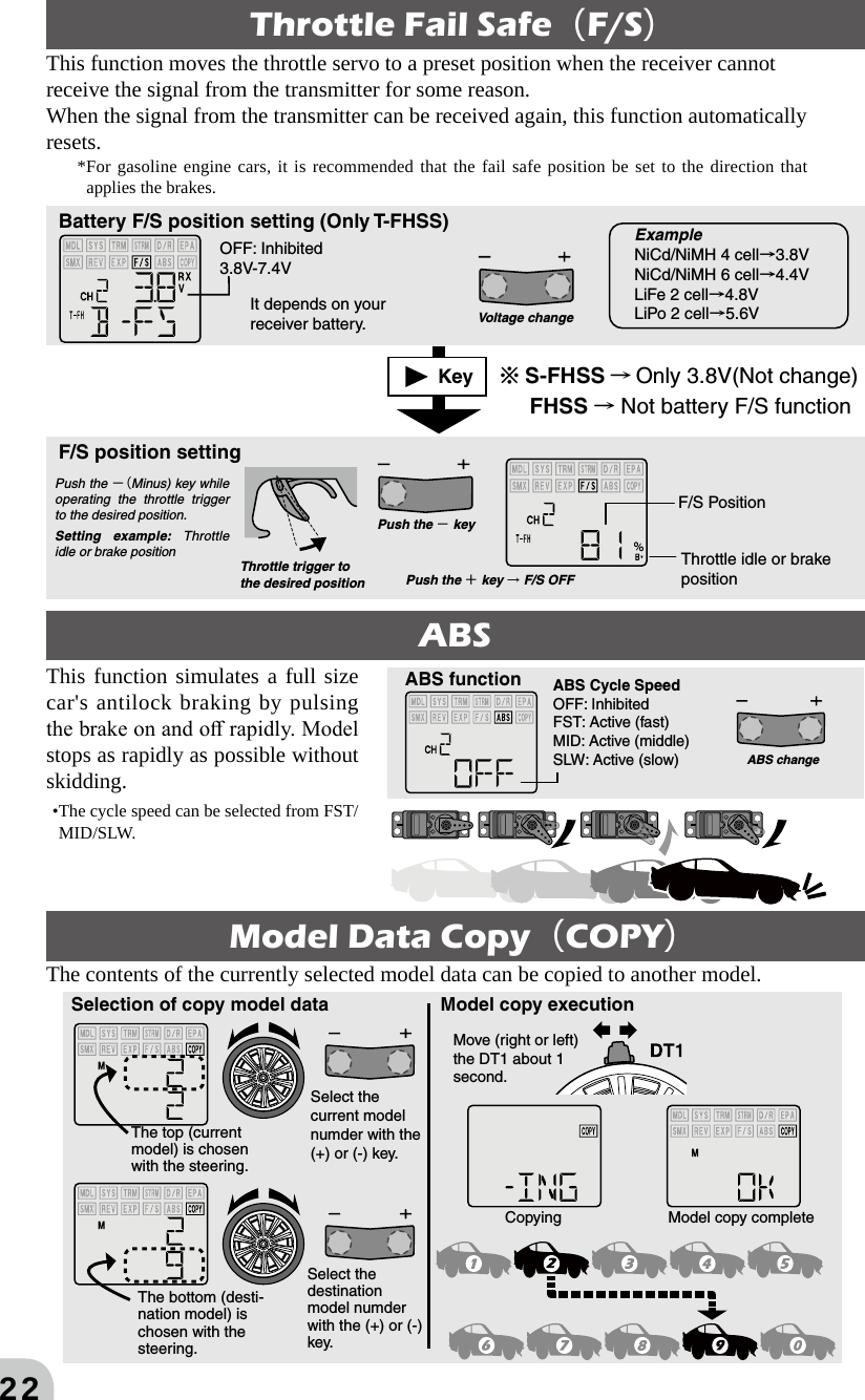
![5[Range Test Procedure]Have a friend hold the model, or place it on a stand where the wheels or prop cannot come in contact with any object. Operate from a distance of about 100 feet. Be sure to check the move-ment of each servo to make sure it follows the movement of the steering wheel and throttle trig-ger. If the servos do not follow the commands from the transmitter or any type of interference is detected, Do Not operate the model. Never operate in the rain or run through puddles. The transmitter, receiver, batteries and most servos and speed controls are not waterproof. Con-tact with any type of moisture or immersion in water or snow will cause damage along with pos-sible loss of control. Should any type of moisture enter any component of the system, immediately stop using the R/C system and return it to our service center for inspection. Do not operate when visibility is limited. Should you lose sight of the model, a collision or other dangerous situation may occur. Do not operate near people or roads. Do not operate on any pond when boats are present.Do not operate near high tension power lines or communication broadcasting antennas.Prior to the operation of any model, be sure the area you plan to use is safe. Be aware of all ob-jects that may be in the path of your model. Do not operate the model where people or any type of moveable object could stray in the path of your model. Control loss due to interference, compo-nent failure, loss of sight or low battery voltage could result in serious injury to yourself and others as well as damage to your model. Do not operate when you are tired, not feeling well or under the influence of alcohol or drugs. Your judgment is impaired and could result in a dangerous situation that may cause serious injury to yourself and others. (Turning on the power switches)Always check the throttle trigger on the transmitter to be sure it is at the neutral position.1. Turn on the transmitter power switch.2. Turn on the receiver or speed control power switch.(Turning off the power switches)Always be sure the engine is not running or the motor is stopped.1. Turn off the receiver or speed control power switch.2. Then turn off the transmitter power switch.If the power switches are turned off in the opposite order the model may unexpectedly run out of control and cause a very dangerous situation. Make all adjustments to the radio control system with the engine not running, or the electric motor disconnected. If the engine is running or the motor is connected while adjustments are made, the model may run out of control. Remove the main battery source from electric powered models when they are not being used.Should you accidentally leave the receiver switch on, the model could run out of control. (Fail safe function)Before running (cruising), check the fail safe function.Check Method:Before starting the engine, check the fail safe function as follows:1. Turn on the transmitter and receiver power switches.2. Turn off the transmitter power switch.3. Check if the fail safe function moves the servos to the preset position when reception fails.The fail safe function is a safety feature that minimizes set damage by moving the servos to a preset position when reception fails. However, if set to a dangerous position, it has the opposite effect.Setting example: Throttle idle or brake position Do not touch the engine, motor, speed control or any part of the model that will generate heat while running.Touching hot parts will result in serious burns. CAUTION When the charger is not in use, disconnect it from the outlet. This will prevent accidents, overheat-ing and short circuits.](https://usermanual.wiki/Futaba/T3PV-24G/User-Guide-3003403-Page-5.png)
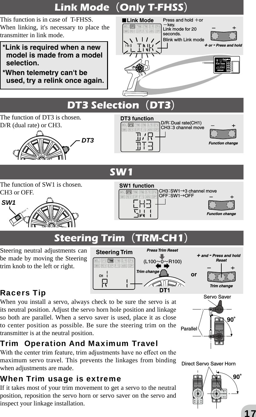
![14Each transmitter has an individually assigned, unique ID code. In order to start operation, the receiver must be linked with the ID code of the transmitter with which it is being paired. Once the link is made, the ID code is stored in the receiver (T-FHSS; and transmitter) and no further linking is necessary unless the receiver needs to be used with another transmitter. (For T/R set, the link is already done at factory.)Link procedure S-FHSS/FHSS (R203GF)1 Bring the transmitter and the receiver close to each other, within 20 inches (half meter).2 Turn on the transmitter and the receiver.3 Push and hold the Link Switch of the receiver.4 When the link is complete, the LED in the receiver changes to solid green. *Please refer to the table below for LED status vs receiver's condition.LED status vs receiver's condition:No signal reception LED : OFFReceiving signals LED: Green ONReceiving signals, but ID is unmatched LED: Green BlinkLink procedure T-FHSS (R304SB/R314SB)1 Bring the transmitter and the receiver close to each other, within 20 inches (half meter).2 Turn on the transmitter.3 Select [LINK] and access the setup screen shown below by pressing the select key [▶]. Next, press and hold [ +] or [ -] key.4 Turn on the receiver.5 During countdown, push and hold the receiver tact switch. The LED will begin to blink red. After the receiver LED switches from blinking red and green red steady light, release the tact switch of the receiver. If the receiver LED lights green, linking was successful. Also check servo operation.*Please refer to the table below for LED status vs receiver's condition.LED status vs receiver's condition:No signal reception Red : OnReceiving signals Green: OnUnrecoverable failure (EEPROM,etc.) LED: Red and Green turn on alternatelyLink Switch LEDHow to Link■Link Mode Press and hold +or -key.Link mode for 20 seconds.Blink with Link mode+ or - Press and holdLink SwitchLED*Link is required when a new model is made from a model selection.](https://usermanual.wiki/Futaba/T3PV-24G/User-Guide-3003403-Page-14.png)