Futaba T6EX2-72 Radio Control Transmitter User Manual 6EXAP 01 ai
Futaba Corporation Radio Control Transmitter 6EXAP 01 ai
Futaba >
Users Manual

INSTRUCTION MANUAL
INSTRUCTION MANUAL
for Futaba 6EXAP
for Futaba 6EXAP
6-channel,
PCM/PPM(FM) selectable
Radio control system for aircraft
Futaba Corporation
Technical updates available at: http://www.futaba-rc.com
Entire Contents © Copyright 2005
FUTZ8563 V1.0
1M23N12007

2
INTRODUCTION
INTRODUCTION
Thank you for purchasing the Futaba® 6EXAP digital proportional R/C aircraft system. If this is your first “computer” radio, rest
assured that it is designed to make initial setup and field-tuning of your airplane easier and more accurate than would be if
using a “non-computer” radio. Although this is a beginner or sport system with the requirements of those flyers in mind, in
order to make the best use of your Futaba 6EXAP and to operate it safely, you must carefully read all of the instructions.
Suggestion:
Suggestion:
If, while reading the instructions, you are unclear of some of the procedures or functions and become “stuck,”
continue to read on anyway. Often, the function or procedure will be explained again later in a different way providing another
perspective from which to understand it. Another suggestion is to connect the battery, switch and servos to the receiver and
actually operate the radio on your workbench as you make programming changes. Then, you’ll be able to see the effects of
your programming inputs.
SERVICE
SERVICE
(in USA)
If any difficulties are encountered while setting up or operating your system, please consult the instruction manual first. For
further assistance you may also refer to your hobby dealer, or contact the Futaba Service Center at the web site, fax
number or telephone number below:
www.futaba-rrc.com
www.futaba-rrc.com
Fax: (217) 398-7721
Fax: (217) 398-7721
Telephone (8:00 am to 5:00 pm Central time Monday through Friday): (217) 398-8970, extension 2
Telephone (8:00 am to 5:00 pm Central time Monday through Friday): (217) 398-8970, extension 2
If unable to resolve the problem, pack the system in its original container with a note enclosed and a thorough, accurate
description of the problem(s). Include the following in your note:
• Symptoms. • Any unusual mounting conditions.
• An inventory of items enclosed. • The items that require repair.
• Your name, address, and telephone number. • Include the warranty card if warranty service is requested.
Send your system to the authorized Futaba R/C Service Center at the address below:
Futaba Service Center
Futaba Service Center
3002 N Apollo Drive Suite 1
3002 N Apollo Drive Suite 1
Champaign, IL 61822
Champaign, IL 61822
This product is to be used for sport and recreational flying of radio-control models only. Futaba is not
responsible for the results of use of this product by the customer or for any alteration of this product,
including modification or incorporation into other devices by third parties. Modification will void any
warranty and is done at the owner’s risk.
(USA only)
(USA only)
Protect the environment by disposing of rechargeable batteries responsibly. Throwing rechargeable
batteries into the trash or municipal waste system is illegal in some areas. Call 1-800-8-BATTERY for
information about Ni-Cd battery recycling in your area.
TABLE OF CONTENTS
TABLE OF CONTENTS
Introduction..............................................................................2
Service......................................................................................2
Contents and specifications .............................................3
Glossary ...................................................................................3
Introduction to the 6EXAP system....................................4
Transmitter controls and descriptions .............................4
Radio installation .................................................................5
Receiver and servo connections ......................................7
Charging the Ni-Cd batteries ..............................................7
LCD and Programming controls........................................8
Programming the T6EXAP radio ........................................9
Model select / Data reset /
Modulation select / Model name...............................10
Servo reversing ...............................................................11
Dual rates ........................................................................11
Exponentials.....................................................................12
End Point Adjustments.................................................12
Tr i ms ..................................................................................13
Programmable Mixer.....................................................13
Flaperon mixing.............................................................14
Flap trim ...........................................................................15
V-tail mixing...................................................................16
Elevon mixing................................................................17
Fail safe..........................................................................18
Flow chart........................................................................19
Other T6EXAP functions ......................................................20
Trainer switch..................................................................20
Flap control lever............................................................20
Adjustable-length control sticks ....................................21
Changing the stick mode...............................................21
Flying safety guidelines ...................................................21
Flight preparation ..............................................................22
Model Data Recording Sheets .........................................23
Futaba Accessories...........................................................24
3
3
GLOSSARY
GLOSSARY
It will be helpful to understand the following terms before reading the rest of the manual. The terms are not in alphabetical
order, but are in a logical order that prepares the reader for understanding the next term.
Reversing (servo reversing) -
Reversing (servo reversing) -
A function that allows the user to determine the direction of response of each servo. If, after
hooking up the servos, a control on the model responds in the wrong direction, the user may change the servo's direction so
the control responds correctly.
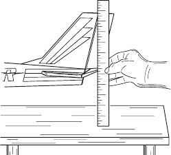
Throw -
Throw -
When speaking of a control surface (such as an elevator or aileron), the throw is
the distance the surface moves. Control surface throw is usually measured at the trailing
edge of the surface and is expressed in inches or millimeters. The model in the diagram has
1/2" [13mm] of up elevator throw. Throw can also refer to the distance a servo arm (or
wheel) travels.
Dual rate (D/R) -
Dual rate (D/R) -
On the 6EXAP the dual rate switch allows you to instantly switch, in flight,
between two different control throws for the aileron, elevator and rudder. Often, different
control throws are required for different types of flying. (“Low” throws may be required for
flying at high speeds where the model’s response becomes more sensitive, and “high”
throws may be required for aggressive aerobatic maneuvers or landing or flying at lower
speeds where the model's response becomes less sensitive.)
End point adjustment (E.P.A.) -
End point adjustment (E.P.A.) -
Sets the overall, maximum distance the servo rotates in either direction. (No matter where
the dual rates are set, the servo will never travel beyond the limit set by the end point adjustment.)
Exponential -
Exponential -
Normally, servos respond proportionally to control stick input from the transmitter (e.g., if the stick is moved
halfway, the servo will move halfway). However, with “exponential,” the servo can be made to move more or less than initial
stick movement (less servo movement is more common). Exponentials are commonly used to “soften,” or decrease initial
servo travel for the ailerons, elevators and rudder. This way, initial control stick inputs from the pilot result in small servo
movement for a smoother flying airplane.
(Dual rates adjust the amount
amount
of servo travel. Exponentials determine where
where
most of the travel will occur.)
Mixing -
Mixing -
Two (or more) servos can be made to operate together either by mechanically joining the wires (with a Y-connector)
or by electronically “joining” them through programming functions in the transmitter. When servos are electronically joined via
programming, they are said to be “mixed.” Unlike joining servos with a Y-connector, when servos are mixed electronically they
can be made to move in opposition. Additionally, each servo’s end points can be independently set.
CONTENTS AND SPECIFICATIONS
CONTENTS AND SPECIFICATIONS
Transmitter: T6EXAP
Transmitter: T6EXAP
T6EXAP Transmitter with programmable mixing and 6-model
memory.
Transmitting on 35, 40, 41, or 72 MHz band.
Operating system: 2-stick, 6-channel system
Modulation: FM(PPM) and PCM
Power supply: 9.6V NT8S600B Ni-Cd battery or 12V alkaline battery
Current drain: 250mA
Receiver: R127DF or R136F
Receiver: R127DF or R136F
R127DF/R136F narrow band, FM 7/6 channel receiver.
Receiving on 35, 40, 41, or 72 MHz band.
Type: FM, Dual conversion/FM, Single conversion
Intermediate frequencies: 455kHz, 10.7MHz/455kHz
Power requirement: 4.8V or 6V
Current drain: 9.5mA @ 4.8V
Size: R127DF- 1.39x2.52x0.82" (35.3x64.0x20.8mm)/
R136F- 1.31x1.98x0.71" (33.4x50.3x18.1mm)
Weight: R127DF- 1.5oz (42.5g) / R136F- 0.98oz (27.8g)
Servos: S3004 or S3003
Servos: S3004 or S3003
S3004 ball bearing/S3003 standard servo with mounting
hardware and servo arm assortment
Control system: Pulse width control,1.52ms neutral
Power requirement: 4.8 or 6V (from receiver)
Output torque: 44.4oz-in [3.2kg-cm] @4.8V
Operating speed: 0.23sec/60˚@4.8V
Size: 1.59x0.78x1.41" [40.4x19.8x36mm]
Weight: S3004- 1.3oz (37.2g) / S3003- 1.3oz (38.0g)
Servos: S3151
Servos: S3151
S3151 Digital standard servo with mounting
hardware and servo arm assortment
Control system: Pulse width control,1.52ms neutral
Power requirement: 4.8 (from receiver)
Output torque: 43.1oz-in [3.1kg-cm] @4.8V
Operating speed: 0.21sec/60˚@4.8V
Size: 1.59x0.79x1.42" [40.5x20x36.1mm]
Weight: 1.48oz (42g)
Other components:
Other components:
Switch harness
9"[200mm]aileron extension cord (to facilitate quick
connecting and disconnecting of aileron servo with
removable wing)
Instruction manual
*Specifications and ratings are subject to change without notice
Aileron & Elevator
dual rate switch
Antenna
Retractable landing
gear switch / CH.5
Flap control
dial / CH.6
Carrying handle
Liquid-crystal display
screen (LCD)
Throttle/rudder
control stick
MODE key
SELECT key
Trainer switch Neck strap hook
Charging jack
On-off switch
Rudder trim
lever
Throttle trim
lever
DATA INPUT lever
Aileron trim lever
Elevator trim lever
Aileron/elevator
control stick
4
INTRODUCTION TO THE 6EXAP SYSTEM
IMPORTANT!: Always turn on the transmitter first, then the receiver. When turning off the system, always turn off the receiver
first. The object is never to have the receiver on by itself. Otherwise, the servos or control surfaces could be damaged, or in
the case of electric-powered models, the motor may unexpectedly turn on causing severe injury.
IMPORTANT!: Never collapse the transmitter antenna by pushing down from the top. If one of the segments becomes momentarily
stuck you may damage the antenna. Instead, collapse the antenna from the bottom, drawing in one segment at a time.
Transmitter
Transmits in both FM (PPM) and PCM by selecting modulation/cycling transmitter. Requires receiver of proper modulation. The
liquid-crystal display (LCD) on the face of the compact, ergonomically-designed case is easy to read and allows rapid data input.
The system also holds independent memories for six different models. The new, adjustable-length control sticks provide an
improved feel. External switches operate dual rates (D/R), landing gear, and trainer cord or “buddy-box” capabilities. Programming
features include servo reversing and E.P.A on all channels, dual rates, exponentials and programmable mixing. Additionally, any
one of four, factory-set, preprogrammed “wing-type” mixers including flaperon, V-tail, elevon mixing may be selected.
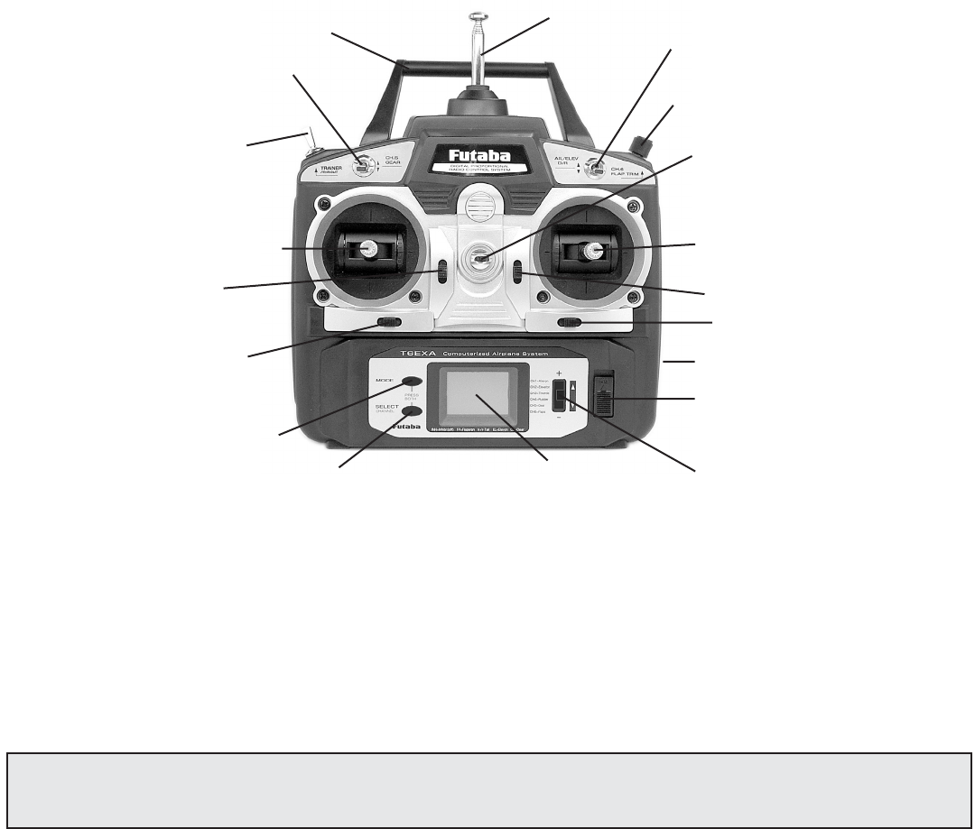
Transmitter controls
The diagram and explanations briefly describe the functions of the Futaba T6EXAP transmitter. Full instructions on how to
operate the controls are provided beginning on page 9.
NOTE: The diagram shows a Mode 2 system as supplied. (More on flight modes on page 21).
DESCRIPTIONS:
Aileron, Elevator and Rudder dual rate switch
Use this switch to “flip” between two aileron, elevator and rudder control throw settings. The throws can be set up however you
prefer, but generally, when the switch is “up” the throws are greater (“high rate”) and when the switch is “down” the throws are
less (“low rate”). This switch also flips between exponential rates (if used).
Flap control dial/Channel 6 - This dial operates the servo connected to channel 6 in the receiver if your model has flaps this is
the control used to operate them.
Neck strap hook -Mounting point for optional neck strap.
Aileron/elevator control stick - Operates the servos connected to channel 1 (aileron) and channel 2 (elevator) in the receiver.
Trim levers (all) - Used to shift the neutral or center position of each servo as labeled in the diagram.
NOTE: The throttle trim lever is intended for fine tuning the throttle servo when the engine is at idle. Throttle trim does
not affect the throttle servo when the throttle control stick is all the way up (so idle r.p.m. can be adjusted without
affecting throttle settings through the rest of the stick movement).
throttle cut
button
5
5
Charging jack - Port for charging the transmitter batteries with the included battery charger.
On-off switch
DATA INPUT lever - Used to change the values of the various functions displayed on the LCD screen.
Liquid-crystal display screen (LCD) - Displays programming modes and values entered.
MODE key - Used to scroll through and display the seven different functions.
SELECT key - Used to display the values for the current function.
Throttle/rudder control stick - Operates the servos connected to channel 3 (throttle) and channel 4 (rudder) in the receiver.
Trainer switch - Operates the trainer functions. To operate as a trainer switch the transmitter must be connected to another
transmitter via. a trainer cord (available separately).
Throttle-cut button - To use the throttle-cut function, lower the throttle stick all the way, then Push the throttle-cut button to
fully close the carburetor and shut of the engine.
Retractable landing gear switch/Channel 5 - Switch operates the servo connected to channel 5 in the receiver if your model
has retractable landing gear this is the control used to extend and retract the gear.
Antenna - Radiates signals to the receiver. Never fly a model without fully extending the antenna or you may create
interference to other modelers and decrease operational signal range of the transmitter. The antenna may be removed and
replaced with another in case it is inadvertently broken.
RADIO INSTALLATION
Follow these guidelines to properly mount the servos, receiver and battery.
• Make certain the alignment tab on the battery, switch and servo connectors is oriented correctly and “keys” into the
corresponding notch in the receiver or connectors before plugging them in. When unplugging connectors, never pull on the
wires. Always pull on the plastic connector instead.
• If any servo wires are not long enough to reach the receiver, servo extension wires (available separately) may be used.
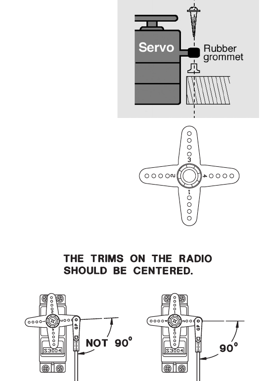
• Always mount the servos with the supplied rubber grommets. Do not over tighten the
screws. No part of the servo casing should contact the mounting rails, servo tray or any
other part of the airplane structure. Otherwise, vibration will be transmitted to the servo
causing premature wear and/or servo failure.
• Note the small numbers (1, 2, 3, 4) molded into each arm on the Futaba 4-arm servo arms.
The numbers indicate how many degrees each arm is “off” from 90 degrees to correct for
minute manufacturing deviations from servo to servo.
• To center the servos, connect them to the receiver and turn on
the transmitter and receiver. Center the trims on the
transmitter, then find the arm that will be perpendicular to the
pushrod when placed on the servo.
6
6
• After the servos are installed, operate each servo over its full travel and check that the pushrods and servo arms do not bind
or contact each other. Also make sure the controls do not require excess force to operate. If there is an objectionable buzzing
sound coming from a servo, there is probably too much resistance in the control. Find and correct the problem. Even if there
is no servo damage, excess battery drain will result.
• Use the mounting plate from the receiver on/off switch as a template for the cutout and screw holes. Mount the switch on
the side of the fuselage opposite the engine exhaust, and where it won’t be inadvertently turned on or off during handling or
storage. Be certain the switch moves without restriction and “snaps” from ON to OFF, and that the cutout allows full motion
of the switch in both directions.
• IMPORTANT: NEVER cut the receiver antenna or mount it in the model folded back on itself. Doing so will change its
electrical length, possibly reducing the distance from the pilot that the model can be controlled (“range”).
• The receiver antenna may be mounted inside or outside the model:
Internal antenna mounting:
The antenna may be routed down through the inside of the fuselage, or through any non-metallic housing or tube within the
fuselage. Keep the antenna away from metal pushrods, wires and cables; otherwise, range may be decreased. Always perform a
range check before flying (see page 22).
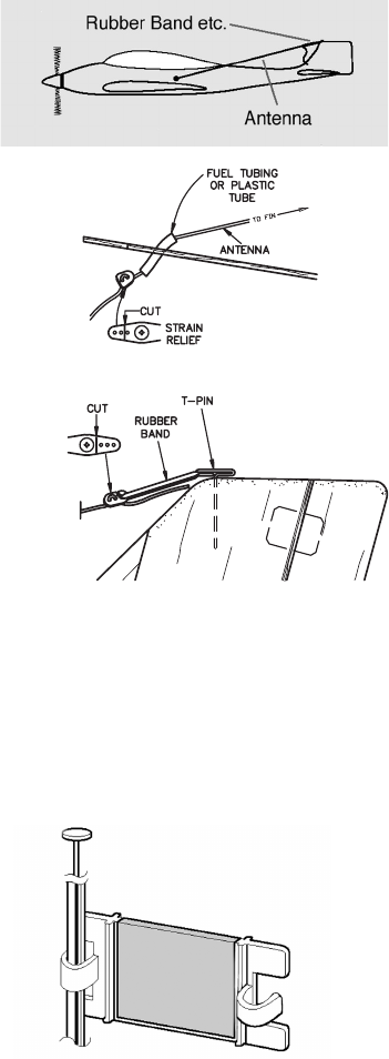
External antenna mounting:
A. Use a cut off servo arm as a “stop” or strain relief inside the fuselage to keep
tension off the solder joint holding the antenna to the receiver. Guide the antenna
through a hole in the fuselage. (If possible, insulate the hole with a rubber grommet or
a small piece of rubber tubing.)
B. Make a hook from another cut off servo arm. Insert the end of the antenna
through two holes, then connect the hook to a rubber band around a pin inserted into the
vertical stabilizer. Allow any excess antenna length to trail behind the hook.
• The receiver contains precision electronic parts. It is the most delicate (and expensive) radio component on-board the model
and should be protected from vibration, shock and temperature extremes. To protect the receiver, wrap it in R/C foam rubber
or other vibration-absorbing material. If appropriate, waterproof the receiver by placing it in a plastic bag and closing the open
end with a rubber band before wrapping it in foam. If moisture enters the receiver, intermittent operation or a failure may
result. Wrapping the receiver in a plastic bag also protects it from fuel and exhaust residue which, in some models, can work
its way into the fuselage.
Mounting the frequency clip: (for USA)
• To announce your frequency and avoid potential interference problems, the
frequency number should always be displayed on the transmitter antenna while
flying. Peel the backing from the numbers and apply them to both sides of the
clip. Snap the end of the clip that fits best to the base of the antenna as shown.
You may cut off the other end of the clip.
Receiver
Charging
Jack
(Black)
Switch
Harness
To Battery
(Red)
7
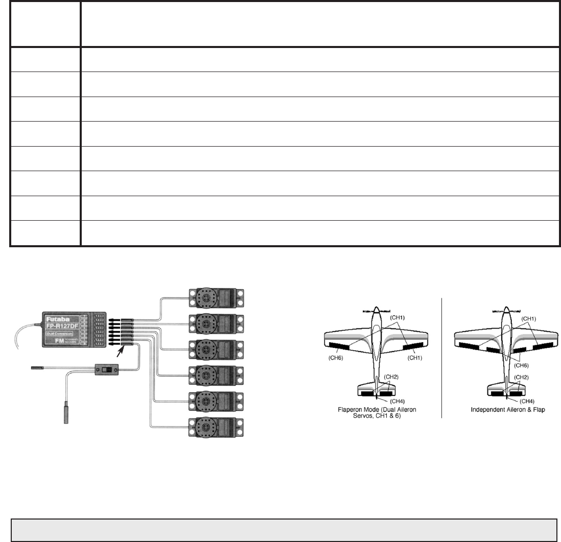
RECEIVER AND SERVO CONNECTIONS
RECEIVER AND SERVO CONNECTIONS
Connect the servos to the receiver to perform the functions indicated:
Connect the servos to the receiver to perform the functions indicated:
Receiver
Receiver
output
output
channel
channel
Function
Function
1
2
3
4
5
6
7
B/8
B/8
Aileron -or
or
-right flaperon -or
or
-right elevon (for tailless models)
Elevator -or
or
-left ruddervator (for V-tail models) -or
or
-left elevon (for tailless models)
Throttle
Rudder -or-right ruddervator (for V-tail models)
Retractable landing gear
Flap -or-left flaperon
Not used
Receiver on/off switch (the plug colored red goes int o the receiver)
The diagram shown is for aircraft models only. Additional servos may have to be purchased separately.
Flap (or 2nd
Flaperon) Servo
(CH6)
Gear Servo
(CH5)
Rudder Servo
(CH4)
Throttle Servo
(CH3)
Elevator Servo
(CH2)
Aileron Servo
(CH1)
CHARGING THE Ni-Cd BATTERIES
CHARGING THE Ni-Cd BATTERIES
The transmitter and receiver batteries included with your 6EXAP system are rechargeable, Ni-Cd (nickel-cadmium, pronounced
ni-kad) batteries. Ni-Cd batteries require special care and charging. Read the charging instructionscarefully.
Read the charging instructionscarefully.
NOTE:
NOTE:
The batteries are supplied partially charged, but will require a full, overnight charge before the model may be flown.
1. Connect the transmitter charging cord
transmitter charging cord
coming from the A/C wall charger to the charge jack in the right side of the
transmitter case. The receiver charging cord
receiver charging cord
may be connected to the batteries two different ways: The charge cord
may be connected directly to the battery pack, or to the vacant charge connector (black) coming from the on/off switch in
the model. Charging “through the switch” is preferred as there will be no need t o disconnect the battery.
2. Plug the A/C wall charger into a wall outlet. Note:
Note:
If the wall outlet can be turned off by a switch in the room, be certain
the switch remains on after leaving the room. Otherwise, the batteries will not be charged!
3. The LEDs (light-emitting diodes) should light red, indicating that current is flowing and the batteries are being charged.
Discharged batteries will take about 15 hours to fully charge. If using an aftermarket fast charger, be certain to follow
be certain to follow
the manufacturer
the manufacturer
’s instructions provided with the charger
s instructions provided with the charger
so you do not overcharge the batteries. NEVER
NEVER
charge
the batteries at a rate higher than 1,000mAh. The batteries should also be discharged periodically to prevent a condition
8
8
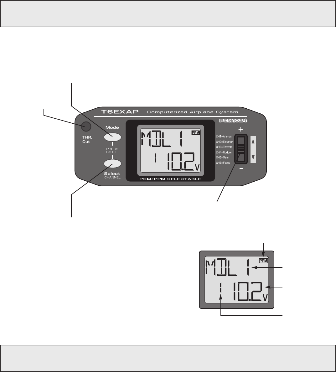
Current model
Current model
memory name
memory name
Modulation
Modulation
indicator
indicator
Transmitter
Transmitter
battery voltage
battery voltage
Current model
Current model
memory number
memory number
LCD display screen
LCD display screen
When the transmitter is initially
initially
turned on, the model memory number
model memory number
,
model memory name
model memory name
, modulation type
modulation type
and transmitter battery
transmitter battery
voltage
voltage
are displayed on the LCD screen. When prompted by the user,
the functions and settings stored in the memory can also be read on the
screen. The user accesses the different functions using the MODE and
SELECT keys and changes the values and settings using the DATA
INPUT lever. (This is called programming!)
Note:
Note:
Feel free to explore by scrolling through the programs and viewing the displays using the MODE and SELECT keys.
The MODE and SELECT keys only determine what will be displayed on the screen and will not change any of the
settings. Only when using the DATA INPUT lever will you be able to change any of the settings.
Note:
Note:
Charging your batteries with the included Futaba A/C battery charger is always safe. However, fast-charging with an
aftermarket charger is acceptable as long as you know how to properly operate the charger. NEVER
NEVER
charge at a rate
higher than 1,000 mAh (1 Amp). If not done correctly, fast-charging can damage the batteries.
called “memory.” If, for example, only two flights are made each time you go flying, the batteries will not have “reached”
very far down into their full capacity. After doing this several times the batteries will “remember” and eventually “think”
they can supply only enough power for two flights. After two flights the batteries may not provide enough power to
operate the system, thus causing a crash. To erase any potential memory, cycle the batteries by discharging, then
charging them with a commercial battery cycler, or leave the system on and exercise the servos by moving the
transmitter sticks until the servos are moving very slowly, indicating that the battery is discharged. Cycling should be done
every one to two months, even during the winter or periods of long storage. If using a cycler with a readout, note the
capacity after the batteries have been cycled. If there is a noticeable drop in capacity the batteries should be replaced.
LIQUID CHIP DISPLAY (LCD) & PROGRAMMING CONTROLS
LIQUID CHIP DISPLAY (LCD) & PROGRAMMING CONTROLS
To open
programming menu;
Press both keys
simultaneously and
hold for one second
MODE key - use to select desired
function while programming
Throttle-cut button -
To use the throttle-cut
function,
SELECT key - use to select items within
function to be set or changed in the screen
DATA INPUT lever - use this lever to input
numbers or settings
9
9
Model memory number and model name
Model memory number and model name
The Futaba T6EXAP stores model memories for six models. This means all the data (control throws, trims, end points, etc.)
for up to six different models can be stored in the transmitter and activated at any time (depending upon which model you
choose to fly that day). This eliminates the requirement for reconfiguring the transmitter each time you decide to fly a different
model with it! When the transmitter is turned on the model number
model number
, model
model
name
name
, modulation and the transmitter voltage will
be indicated on the LCD screen. Before every flight BE CERTAIN
BE CERTAIN
that the correct model number for the model you intend to
fly appears on the screen. If the transmitter is not operating the correct model, some (or all) of the controls could be reversed
and the travels and trims will be wrong.
Flying a model with the wrong program will result in a crash, so always be certain
be certain
the model number andmodel name in the
transmitter is correct. One way to ensure this is to write the corresponding model number directly on the airplane, or attach a
list to the bottom or back of the transmitter.
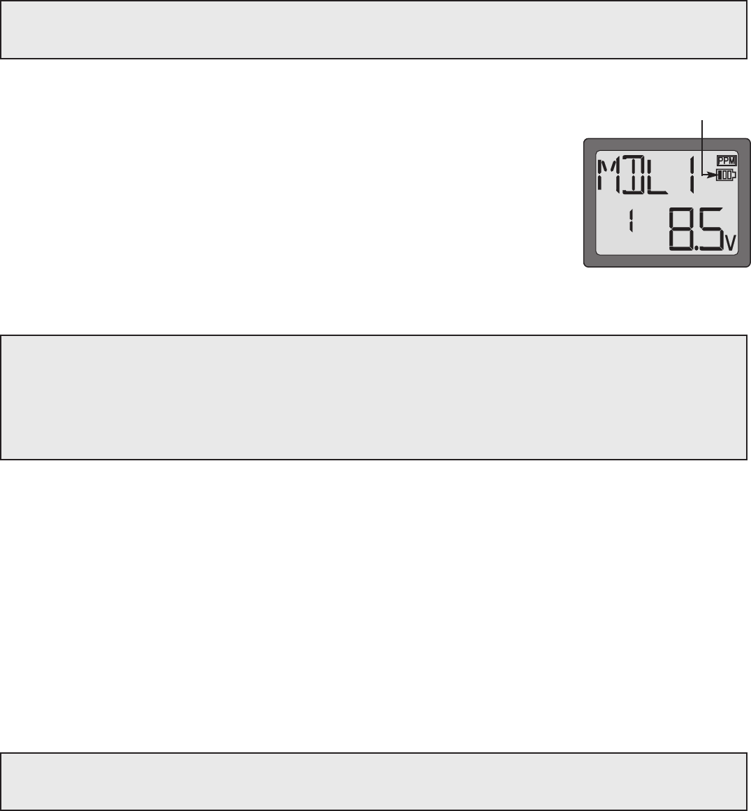
Transmitter battery voltage
Transmitter battery voltage
In addition to the model number, the LCD screen also displays the transmitter battery
transmitter battery
voltage
voltage
. When the voltage goes below approximately 8.5 Volts
8.5 Volts
the “battery” icon will flash and
the low-battery alarm will continuously “beep” until the transmitter is turned off. When the low-
battery alarm sounds you will have approximately four minutes (or less) to land your model
before losing control. You should never allow the transmitter voltage to become this low while
flying, but if it does, land immediately
immediately
.
PROGRAMMING THE 6EXAP RADIO
PROGRAMMING THE 6EXAP RADIO
Anytime you wish to view
view
or change
change
any of the current settings in the transmitter, the programming mode must first be entered
by, of course, turning on the power, then by pressing the “MODE
MODE
” and “SELECT
SELECT
” keys simultaneously and holding them down
for one second. Once “in the program” the MODE key will be used to scroll through each of the ten or elevn(PCM) functions
(model number/ data reset/ modulation select/ model name, reversing, dual rates/ exponentials, end point adjustments, trim,
programmable mix, “flaperon” mixing, “v-tail” mixing, “elevon” mixing, flap trim and failsafe) and the SELECT key will be used to
view the settings within the function. When a data change is actually required the “DATA INPUT
DATA INPUT
” lever will be used to increase
or decrease the value of the item displayed, thus making the change.
You can return to the “home” screen (where the model number and battery voltage is displayed) by pressing the MODE and
SELECT keys simultaneously and holding them down for one second.
Note:
Note:
The functions are listed and described in the order that they appear in the transmitter. Read all the way through the
programming instructions before setting up your model (if you won’t be using any of the mixing functions for a while you can
read those instructions when ready). Refer to the FLOW CHART on page 19 as well.
Note:
Note:
When the transmitter voltage reads 8.9 Volts
8.9 Volts
you
will still have approximately ten minutes (or less) before
losing operational range, so this is the recommended
absolute minimum
absolute minimum
voltage. If the transmitter ever
reaches 8.9 Volts, land as soon as safely possible. A more
reasonable margin of safety would be to quit flying for the
day (or recharge the batteries) when the transmitter battery
SUGGESTED GUIDELINES
SUGGESTED GUIDELINES
9.4 Volts - No more flying until recharge.
8.9 Volts - Land as soon as safely possible.
8.5 Volts - Emergency- Land immediately!
Emergency- Land immediately!
“Battery
Battery
” icon
icon
10
10
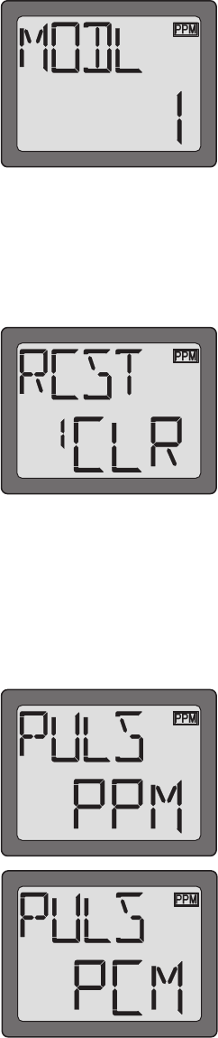
Model Select/Data Reset / Modulation Select/Model Name
Model Select/Data Reset / Modulation Select/Model Name
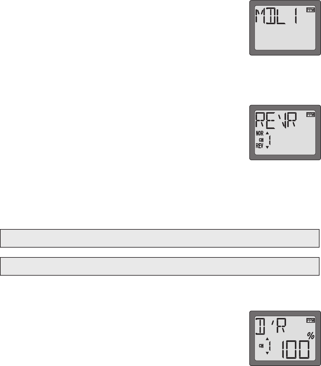
MODL Model select function
MODL Model select function
To select model memory:
To select model memory:
1. Access the Model Select function in the programming mode (by pressing the MODE and
SELECT keys simultaneously and holding them down for one second). The number for the
current, active model will be blinking.
2. To activate a different model memory press the DATA INPUT lever until the desired model
number appears.
3. Now the model has been selected. All programming inputs from this point forward will affect
only the model number on the screen (until another model number is selected).
RCST Data reset function
RCST Data reset function
All the data for any model memory can be reset to the original factory defaults. Often this function is done to get a “fresh start”
and clear the memory before inputting new model settings.
To reset data:
To reset data:
1. Access the Model Select function in the programming mode (by pressing the MODE and
SELECT keys simultaneously and holding them down for one second). Use the DATA INPUT
lever to select the model memory you wish to reset.
2. Once the desired model number is displayed on the screen, press the SELECT key. A “REST
REST
”
will appear on the screen.
3. Press the DATA INPUT up or down for two seconds to clear and reset the memory. Now the
data for this model has been reset to the original, factory defaults.
CAUTION:
CAUTION:
Resetting the current model memory will permanently erase ALL
ALL
programming information for that model. The
data cannot be recovered (unless you recorded it on a Model Data Recording Sheet in the back of this manual). Do not reset
the model unless certainly
certainly
you want flushing-out that memory and start from scratch.
When actually setting up a model you should have the model in front of you with the power on so you can actually see the
effects of your programming inputs and measure the control throws.
PULS Modulation select function
PULS Modulation select function
The Modulation select function is used to select the PPM
PPM
or PCM
PCM
mode of transmission, to
match the receiver being used (PPM-Pulse Position Modulation, also called FM for Frequency
Modulation, and PCM-Pulse Code Modulation).
To select modulation:
To select modulation:
1. Access the Model Select function in the programming mode (by pressing the MODE and
SELECT keys simultaneously and holding them down for one second). Use the DATA INPUT
lever to select the model memory you wish to modulation select.
2. Once the desired model number is displayed on the screen, press the SELECT key. A
“PULS
PULS
” will appear on the screen.
3. To select PCM modulation, push the DATA INPUT lever up. The “PCM
PCM
” is displayed. To select
PPM modulation, push the DATA INPUT lever down. The “PPM
PPM
” is displayed.
4. To get the transmitter to operate in the new mode, switch transmitter power off and then on.
The small indicator will indicate the mode, either PPM or PCM.
Model name function
Model name function
Assign a name to the model memory. By giving each model a name that is immediately recognizable, you can quickly select the
correct model, and minimize the chance of flying wrong model memory that could lead crash.
1. Access the Model Select function in the programming mode (by pressing the MODE and SELECT keys simultaneously and
holding them down for one second). Use the DATA INPUT lever to select the model number you wish to change.
11
11
2.Once the desired model number is displayed on the screen, press the SELECT key. A NAME
will appear on the screen.
3. Choose a character for the first digit by using DATA INPUT lever. Then move to the next digit
by pressing the SELECT key and choose a character in the same way. Continue choosing
characters for the third and fourth digits. You can use up to four characters for the name.
REVR Servo Reversing
REVR Servo Reversing
The servo reversing function is used to change the direction that a servo responds to a control input from the transmitter
(stick, dial or switch). After using the reversing function, check all
all
the controls on the model to be certain
be certain
they are operating
in the correct direction and that you did not inadvertently reverse a servo other than the one intended. Reversing the wrong
servo (and not checking the response of the controls before each flight) may be the most common cause of a crash!
To reverse a servo:
To reverse a servo:
1. Enter the programming mode and use the MODE key to access the REVR
REVR
function.
2. Use the SELECT key to select the channel you wish to reverse.
3. Push the DATA INPUT lever downward to reverse the servo (REV), or push the lever upward
to make the servo operate normally (NOR). The arrow will indicate the condition of the servo
(normal or reversed). In the diagram channel 1 (aileron) is “normal” (not reversed).
4. Use the SELECT key to display other channels to be reversed.
Dual Rates / Exponential Settings
Dual Rates / Exponential Settings
The aileron, elevator and rudder dual rates on the 6EXAP are simultaneously activated by the dual rate switch. The amount of
travel decrease for each control may be set between 0% and 100% of the values set for the end points (explained in End
Point Adjustment on page 12).
Note:
Note:
It is possible to set a dual rate value to zero, thus causing no response from that channel. If the dual rates are
inadvertently set to zero, a crash could result.
Note:
Note:
When performing initial model setup, the E.P.A.s should be set prior to
prior to
setting the dual rates. When setting the
E.P.A.s for the first time on a new model, the dual rates should be set to 100%.
D/R Dual Rate Settings
D/R Dual Rate Settings
To set the dual rates:
To set the dual rates:
1. Enter the programming mode. Access the “D/R
D/R
“ screen with the MODE key.
2. Select the channel to be adjusted (1-aileron, 2-elevator, 4-rudder) by pressing the SELECT
key until the desired channel number the left side on the screen. Note: If a “EXPO
EXPO
“ will
appear on the screen, you have pressed the SELECT key too many times and displayed the
values for the exponentials (explained later). Press the SELECT key to return to the dual rate
values.
3. Place the dual rate switch in the desired position for the value you wish to change.
(Generally, pilots prefer to have the switch in the “up” position for the high rate, and in the
“down” position for the low rate.)
4. Change the dual rate value using the DATA INPUT lever until the desired control throw is achieved. If you wish to change
the control throw when the switch is in the other position as well, flip the switch, then use the DATA INPUT lever to change
the throw.
5. Repeat the procedure for the other dual rate (channel 2-elevator, 4-rudder).
12
12
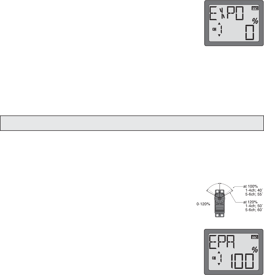
EXPO - Exponential Settings
The “exponentials” are in the same function as the dual rates. (Pressing the MODE key will take you to the next function
which is End Point Adjustments). The same as dual rates, “expos” can be set for both switch positions. Negative exponential
(-) decreases initial servo movement. Positive exponential (+) increases initial servo movement. The exponential “curve”
may be set anywhere between -100% and +100%.
To set the exponentials:
1. Enter the programming mode. Access the “D/R“ screen with the MODE key.
2. Access the “EXPO“ screen with the SELECT key.
3. Select the channel (1-aileron, 2-elevator, 4-rudder) you wish to set by pressing the SELECT
key. The active channel number will be displayed on the screen Note: If a “D/R“ will appear
on the screen, you have pressed the SELECT key too many times and displayed the
values for the D/R (dual rate values). Press the SELECT key to return to the exponentials.
4. Position the dual rate switch where desired for the value you wish to change.
5. Enter the amount of exponential with the DATA INPUT lever. (As stated above, an exponential value with a “-” in front of it
makes the initial servo movement less, or “softer.”)
6. Flip the switch to the other position to enter the exponential value for that switch position.
7. Repeat for the settings on the other channel.
EPA - End Point Adjustment
Note: Since changing the “end points” will also change the dual rates, the end points should be set prior to setting the dual
rates. If you set the dual rates first, and then go back and change the end points, the dual rate throws will also change.
The EPA function is designed to “fine tune” the servo throws in cases where changing the pushrod hookup will not achieve the
correct throw. The pushrods should first be connected to the servo arms and control horns so the correct, or near correct control
surface throw will be achieved. THEN the EPAs may be used to make small changes in the servo throw until the desired control
throw is achieved. The control throws should be set up so that the “end points” are as near to 100% as possible. If the EPA
values must be set below 70% or above 120% to get the desired throw, you should strongly consider changing the pushrod
connections so the values can be set closer to 100%. (When the EPA is set to 100% the maximum servo throw for channels 1,
2, 3 & 4 is approximately 40 ˚ and approximately 55 ˚ for channels 5 & 6.)
To set the end points:
1. Enter the programming mode and use the MODE key to access the “EPA” screen. The
channel number being adjusted will the left side on the screen and the % symbol will be
flashing.
2. To change the RIGHT aileron throw move the aileron stick to the right, then push the DATA
INPUT lever up or down to change the value and the throw.
3. Move the stick to the left and use the DATA INPUT lever to change the LEFT aileron throw.
4. Use the SELECT key to display the other channels and set the other end points. Notice that
moving the stick (or switch or dial) from one end to the other changes the value displayed and
the position of the arrow for that “end” of the control input.
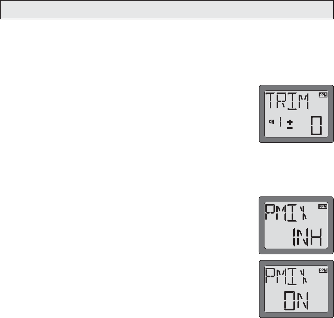
TRIM - Trim Settings
There are four trim levers (“trims”) on the front of the transmitter. Three of the trims are for adjusting the neutral position of
the aileron, elevator and rudder servos. The fourth trim is for setting the idle r.p.m. of the engine when the throttle stick is all
the way down. The intended use of the trims is to make small servo adjustments, in flight, to get the model properly
“trimmed” (so it will fly straight-and-level). Because the trims are intended to be used while the model is in flight, you do not
have to “enter the program” to adjust the trims. Simply push or pull on the trim levers while flying and the neutral position of
the servos will shift. Keep in mind that you should start out with the control surfaces centered when the servos are centered
and the trims are “zeroed” (or near zero). THEN you can adjust the trims once airborne.
Center the servos:
1. Turn on the transmitter and receiver. Operate the controls to make sure the servos respond in the correct direction. Use
the reversing function to reverse any servos necessary.
2. Center the throttle control stick.
3. Place the servo arms on the servos so they are perpendicular to the pushrods (see page 5). It is okay to cut off any
unused servo arms.
4. Connect the pushrods to the control surfaces. Adjust the length of the pushrods until the control surfaces are centered
when the servos are centered.
Note: The throttle trim affects the throttle servo only when the throttle stick is below “1/2 stick.” This way, the final closing
of the carburetor can be adjusted without affecting the servo throughout the rest of the range.
To adjust the trim settings:
Once the servos and control surfaces have been connected and the control throws have been set using the end points and
dual rates, get the model airborne. Adjust the trims as necessary to get the model to fly straight-and-level. If much trim is
required on any one control it is a good idea to readjust the pushrods so the trims can be returned to neutral (zero). Adjusting
the trims with the trim levers changes the servo’s position in increments of “4.” If finer adjustments are required, land the
model, then enter the program as described below to adjust the trims in increments of “1.”
1. Enter the programming mode and use the MODE key to activate the TRIM menu.
2. Press the SELECT key to display the channel to be adjusted (the figure shows trim
adjustment for CH1).
3. Adjust the trim using the DATA INPUT lever. Note that initially, the values change in
increments of “1,” but if the DATA INPUT lever is held long enough the values will change
more rapidly.
4. Repeat the steps for other channels that require trim adjustments.
PMIX - Programmable Mixer
Unlike the “wing mixing” function (explained later) where the channels to be mixed are factory-set, the T6EXAP also contains
one programmable mix where the you, the pilot determine the channels to be mixed. This could be used to correct unwanted
flight tendencies (by mixing rudder to aileron, or aileron to rudder for example).
To set up a programmable mix:
1. Enter the programming mode. Access the “PMIX” screen with the MODE key.
2. Push the DATA INPUT lever upward. This will cause the flashing “INH” display to change to
a flashing “ON” display.
13
13
14
14
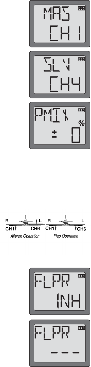
3. Select the channel that will control the mix (called the master) by access the “MAS” screen
with the MODE key, then pressing the DATA INPUT lever to select the channel number
desired. The channel on with the screen the master. In the diagram channel 1 (aileron) is
the master.
4. Select the channel that will be mixed (called the slave) by access the “SLV” screen with
the MODE key, then press the DATA INPUT lever to select the desired channel. The
channel on the screen with the slave. In the diagram channel 4 (rudder) is the slave.
5. Press the SELECT key twice to display the flashing % sign. Use the DATA INPUT lever to
set the percentage of mixing from -100% to +100% (depending on the direction and
distance you wish the slave servo to move).
6. Observe how the controls on the model respond to be certain you have achieved the correct mix and that the throws are
as desired.
Wing Mixing Type Selection
With the programmable mix (previously described) the user determines the two channels to be mixed. The wing mixing
function is another mix that may be used, but the channels mixed are predetermined. There are four different wing mixing
functions to select from:
FLPR - Flaperon mixing
This function allows the ailerons to be used both as ailerons and as flaps. The
flap control dial (CH 6) operates the flap function. To use flaperon mixing both
ailerons must be operated by separate servos.
To activate flaperon mixing:
1. Connect the aileron servo in the right wing to channel 1 (aileron) in the
receiver and connect the aileron servo in the left wing to channel 6 (flaps)
in the receiver.
2. Enter the programming mode. Access the “FLPR” screen with the MODE key.
You cannot set “Flaperon” mixing when “Elevon” mixing has already been set. In order to
enable “Flaperon” mixing, you first need to cancel “Elevon" mixing. However, it is allowed
to use “Flaperon” and “V-Tail” mixing simultaneously.
*If necessary, use the Servo Reversing
function to achieve the correct direction of
servo throws.
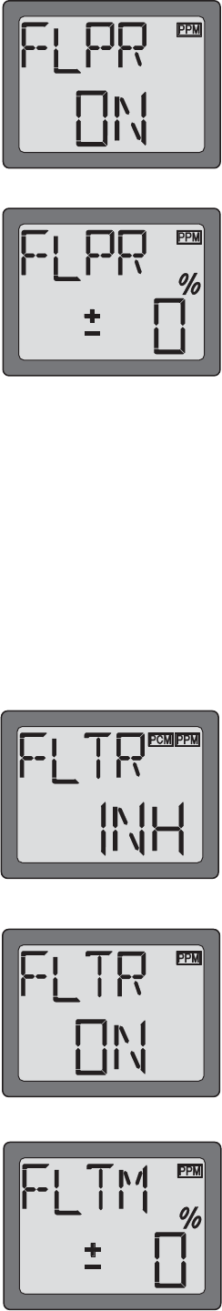
3. Push the DATA INPUT lever upward. This will cause the flashing “INH” display to change to
a flashing “ON” display. Now the mixing is on. The servo travels for the aileron and flap will
automatically be reduced to 60% and 40% respectively, but full servo throw will still be
achieved when both the aileron stick and the flap control dial are moved to their full
extremes.
4. Next you set ailerons differential. Press the SELECT key to display the flashing “%” sign. Use
the DATA INPUT lever to set the percentage of ailerons differential from -100% to +100%
(The “-” direction indicates decreasing amount of movement toward the upward from the
aileron surface, while “+” direction indicates decreasing amount of movement toward the
downward from the aileron surface.)
5. Once this mix has been activated, move the servos to their full extremes to make certain they are not overdriving the
controls. If necessary, adjust the linkages to achieve the correct control throws.
FLTR - Flap trim
The Flap Trim function is used to specify the amount of flap travel produced moving the flap control (the Flap control dial).
As normal flap control dial will be inhibited to use if the flaperon function is activated, the Flap Trim function should be
activated if you need to control flap by Flap control dial.
To activate flap trim:
1. Enter the programming mode. Access the “FLTR” screen with the MODE key.
2. Push the DATA INPUT lever upward. This will cause the flashing “INH” display to change to
a flashing “ON” display. Now the flap trim is on.
3. Next you may the ailerons differential. Press the SELECT key to display the flashing % sign.
Use the DATA INPUT lever to set the percentage of flap trim rate from -100% to +100% (The
“-” direction indicates decreasing amount of movement toward the upward from the aileron
surface, while “+” direction indicates decreasing amount of movement toward the downward
from the aileron surface.)
15
15
16
16
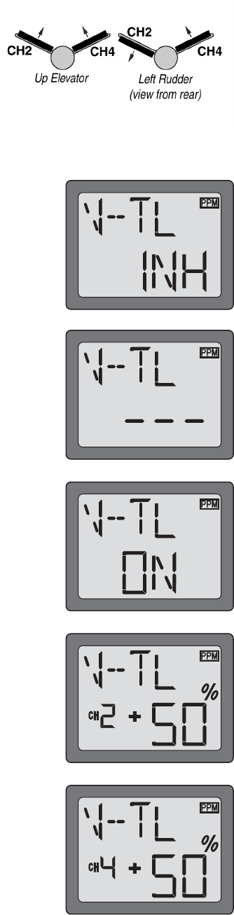
V-TL - V-tail mixing
Intended for V-tail aircraft (such as a Beechcraft Bonanza), V -tail mixing allows the ruddervators to operate both as rudders
and elevators. The same as the other mixes, V -tail mixing requires that each ruddervator be operated by a separate servo.
To activate V-tail mixing:
1. Connect the left ruddervator servo to channel 2 (elevator) in the receiver and
connect the right ruddervator servo to channel 4 (rudder) in the receiver.
2. Enter the programming mode. Access the “V-TL” screen with the MODE key.
You cannot set “V-tail” mixing when “Elevon” mixing has already been set. In order to
enable “V-tail” mixing, you first need to cancel “Elevon” mixing. However, it is allowed to
use “V-Tail” and “Flaperon” mixing simultaneously.
3. Push the DATA INPUT lever upward. This will cause the flashing “INH” display to change to
a flashing “ON” display. Now the mixing is on.
4. Next you may the elevator setting. Press the SELECT key to display the “CH2” and flashing
“%” sign. Use the DATA INPUT lever to set the percentage of elevator travel rate from -
100% to +100%
5. Next you may the rudder setting. Press the SELECT key to display the “CH4” and flashing
“%” sign. Use the DATA INPUT lever to set the percentage of rudder travel rate from -100%
to +100%
6. Once this mix has been activated, move the servos to their full extremes to make certain they are not overdriving the
controls. If necessary, adjust the linkages to achieve the correct control throws.
*If necessary, use the Servo Reversing
function to achieve the correct direction of
servo throws.
CH1 CH2
17
17
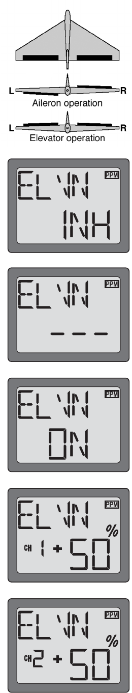
ELVN - Elevon mixing
Intended for tailless, “flying wing” models such as delta wings and flying wings,
elevon mixing mixes channel 1 (aileron) to channel 2 (elevator) allowing the
elevons to operate in unison (as elevators) or in opposition (as ailerons). This
function requires that each elevon be operated by a separate servo.
To activate elevon mixing:
1. Connect the servo in the right wing to channel 2 (elevator) in the receiver and connect the
servo in the left wing to channel 1 (aileron) in the receiver.
2. Enter the programming mode. Access the “ELVN” screen with the MODE key.
You cannot set “Elevon” mixing when “Flaperon” or “V-TL” mixing has already been set. In
order to enable “Elevon” mixing, you first need to cancel both “Flaperon” and “V-tail” mixing.
3. Push the DATA INPUT lever upward. This will cause the flashing “INH” display to change to
a flashing “ON” display. Now the mixing is on.
4. Next you set the left wing to channel 1 (aileron) setting. Press the SELECT key to display the
“CH1” and flashing “%” sign. Use the DATA INPUT lever to set the percentage of elevator
travel rate from -100% to +100%
5. Next you set the right wing to channel 2 (elevator) setting. Press the SELECT key to display
the “CH2” and flashing “%” sign. Use the DATA INPUT lever to set the percentage of rudder
travel rate from -100% to +100%
6. Once this mix has been activated, move the servos to their full extremes to make certain they are not overdriving the
controls. If necessary, adjust the linkages to achieve the correct control throws.
*If necessary, use the Servo Reversing
function to achieve the correct direction of
servo throws.
18
18
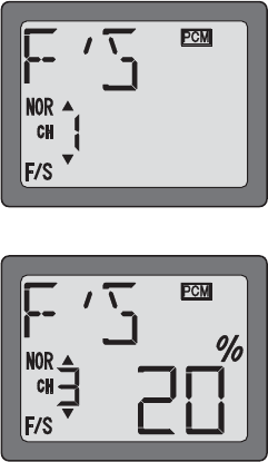
F/S - Fail Safe (PCM mode only)
The Fail Safe function is used to prescribe what the PCM receiver will do in the event radio interference is received, and
doesn’t work FM(PPM) receivers. In this menu, you may select from one of two options of operation for each channel. The
“NOR”(normal) setting holds the servo in its last commanded position, while the “F/S”(Fail Safe) function moves each servo
to a predetermined position.
Throttle channel is set to “F/S” as a default. All the other channels are set to “NOR”.
The use of the failsafe function is recommended from the standpoint of safety. You may wish to set the throttle channel so
that the throttle is moved to idle when there’s interference. This may give enough warning to allow you to fly towards yourself
and recover from the radio interference. If you choose to specify a failsafe setting, the failsafe data are automatically
transmitted once each minute.
Battery Failsafe
Your system provides a second safety function called Battery Failsafe. When the airborne battery voltage drops below
approximately 3.8V, the battery fail safe function moves the throttle to a predetermined position or fast idle, if you haven’t set
it. If this happens, you should immediately land! If you need to increase throttle for your landing approach, you may
temporarily reset the failsafe function by moving the throttle stick to idle, after which you’ll have about 30 seconds of throttle
control before the battery function reactivates.
To set the Fail Safe Function:
1. Enter the programming mode. Access the “F/S” screen with the MODE key.
2. You can find the channel blinking on the left of the screen, which can be set to the Fail Safe.
The first channel you see is CH1 (aileron). Press DATA Input lever downward when you
need to set Fail Safe. The arrow moves to F/S side. This means this channel has been set
to F/S function. Then move the aileron stick to the position where you want the servo to
move when “F/S” function works and press DATA INPUT lever downward for about two
seconds while holding the stick. A figure in percentage will be shown with a beeping sound.
Press DATA INPUT lever upward if you want to set “NOR”. The arrow moves to “NOR”
side and then this channel will be set to “NOR” function.
3. Carry out similar procedure like this in setting “F/S” function for other channels. Use Mode
key to show a channel and do the same. But, CH3 (throttle) is set to 20% of the full throttle
for “F/S” function as a default.
4. Verify that your failsafe programming works by switching off transmitter power and observing the motion of the servos.
19
19
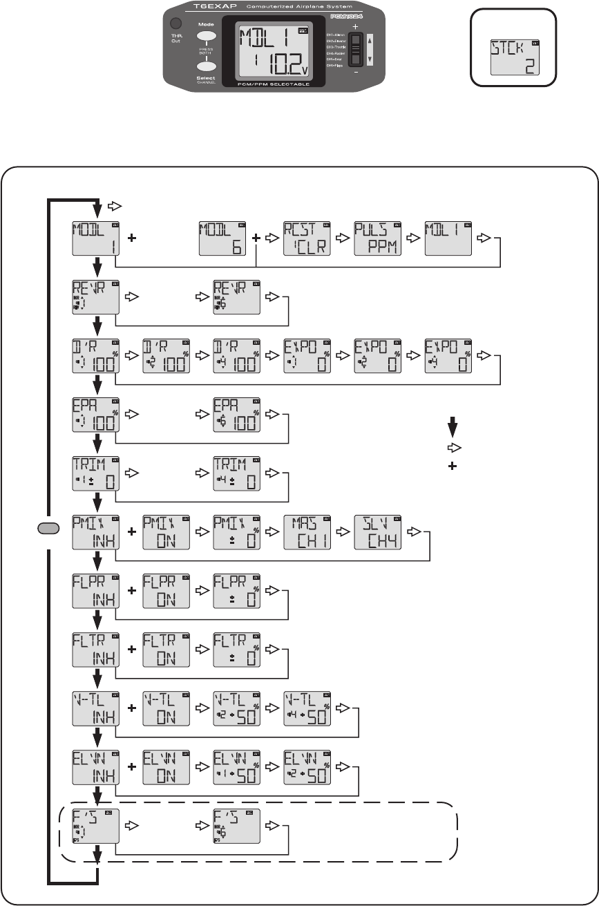
MODE key
MODE key
PCM mode onry
SELECT key
DATA INPUT
lever
[CH 2-5]
[CH 2-5]
[CH 2-3]
[Model 2-5]
[CH 2-5]
To enter or leave Programming Mode,
press MODE and SELECT keys
simultaneously for one second.
To change the Stick Mode, turn on
the transmitter holding MODE and
SELECT keys down simultaneously.
Use the DATA INPUT lever to display the
desired stick mode.
FLOW CHART
FLOW CHART
6EXAP FUNCTIONS
6EXAP FUNCTIONS
Simultaneously Press the “MODE
MODE
” and “SELECT
SELECT
” keys and hold them down for one second to enter the programming
mode. Press the keys again (or turn off the transmitter) to exit the programming mode.
(Screen at Startup)
Stick Mode
Stick Mode
(press MODE and SELECT keys for one second)
20
20
OTHER 6EXAP FUNCTIONS
OTHER 6EXAP FUNCTIONS
Trainer switch
Trainer switch
To utilize the trainer function, the appropriate trainer cord (available separately) and a second Futaba transmitter (usually
provided by your flight instructor or R/C club) will be required. When two radios are connected with the trainer cord, they are
both capable of operating the model, but it's usually best for the instructor to hold the radio that has been setup for the plane
to be flown (as it is already programmed to fly the model). When the instructor holds the trainer switch on his radio, the
student will have control. When the instructor wishes to regain control he simply releases the switch. Then he will have
immediate, full control.
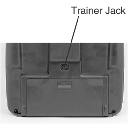
If connecting the 6EXAP to another 6EXAP with the small, square “micro” trainer jack, use the “Micro to Micro” (MM-TC)
trainer cord (FUTM4415). If connecting the 6EXAP to Futaba radios with the larger, round, “DIN” connector, use “Micro to
DIN” (MD-TC) trainer cord (FUTM4420). The T6EXAP transmitter may be connected to another T6EXAP, or any 4VF, 6VA
Skysport, T6EXA, FF6 - 9, or 9Z series transmitter.
To use the trainer cord:
To use the trainer cord:
1. It is best for the instructor to use the transmitter that is already set up for the model to be flown.
2. If the student's radio has PCM/PPM capability, set it to PPM.
3. If the student's radio has a plug-in RF module, remove the module.
4. Collapse the student's antenna and fully extend the instructor's antenna.
5. With the transmitters off, connect the trainer cord to both radios. (On the 6EXA the trainer
jack is in the center of the rear of the case.) Do not force the plug into the transmitter and
note that the plug is “keyed” so it can go in only one way.
6. Turn on the instructor's transmitter. DO NOT
DO NOT
turn on the students transmitter it will automatically “power up,” but will not
transmit a signal. Set the servo reversing and trims of the student's radio to match that of the instructor's.
7. Turn on the receiver switch in the model. Depress the trainer switch on the instructor's radio. Use the student’s radio to
operate the controls (ailerons, elevator, rudder, etc.) and observe how they respond. Make any adjustments necessary to
the student's transmitter to get the controls to respond correctly.
8. Check to see that the trims are in “sync” by toggling the trainer switch back and forth a few times. The controls on the
model should remain stationary. If the controls do not remain stationary, this indicates that the trim settings on the
student's radio do not match those on the instructor's radio. Adjust the student's trims as necessary.
Note:
Note:
When the instructor initially depresses the trainer switch on his transmitter, there will be a one-second delay before the
student takes control. In most situations this momentary delay will go unnoticed.
Throttle-cut function
Throttle-cut function
The throttle-cut function is intended to be used for shutting off the engine. The engine can be conveniently shut off by
pressing the "THR Cut" button. The throttle-cut feature prevents inadvertently shutting off of the engine when lowering the
throttle stick all the way (such as when coming in for a landing or taxiing). Throttle-cut works only when the throttle stick is
down. To set up throttle-cut, turn on the transmitter and receiver. Actuate the throttle-cut function by rapidly depressing, then
releasing the switch twice. Observe the momentary position of the carburetor barrel on the engine. It should be fully closed
(thus shutting off the engine). If necessary, use the throttle E.P.A. (channel 3) to fully close the carburetor barrel when the
throttle-cut is activated. Now use the throttle trim to open the carburetor barrel so the engine will idle at the desired R.P.M.
when the throttle stick is all the way down.
Optional Flap control lever (Option)
Optional Flap control lever (Option)
When the flaperon mixing function is activated, the optional flap control lever
flap control lever
can be used to set maximum flap deflection
by mechanically limiting the dial. This will prevent inadvertently retracting the flaps beyond their full, "up" position. To use the
flap control lever, turn the flap dial until the flaps are retracted (up). Place the flap control lever over the dial so that the arm is
contacting the transmitter case. This will limit rotation of the dial so the flaps cannot go up any farther.

21
21
Adjustable-length control sticks
Adjustable-length control sticks
The control stick length is adjustable to make the transmitter more comfortable to
hold and operate. To adjust the length, hold the locking piece (B)
locking piece (B)
and turn the
stick tip (A)
stick tip (A)
counterclockwise. Turn the locking piece B up or down to lengthen or
shorten the stick. When the length is suitable, lock the stick in position by turning
locking piece B counterclockwise.
Changing the 6EXAP stick mode
Changing the 6EXAP stick mode
The transmitter may be operated in four different stick “modes” (1, 2, 3 & 4). The modes
determine the functions that will be operated by control sticks. Currently, the transmitter is in
“mode 2” and should be left in mode 2 unless you are an experienced flyer and have learned to
fly in a different mode. In mode 2, the right control stick operates the aileron and elevator and
the left stick operates the rudder and throttle. This is how 99% of Americans fly their models.
To change the mode, simultaneously depress the MODE and SELECT keys, then turn on the power. The current mode will
appear on the LCD screen. Push the DATA INPUT lever up or down to change the mode. If a mode is selected that moves
the throttle control to the right stick, the throttle detent mechanism will have to be moved as well. This can be done by the
Futaba Service Center. (See page 2)
FLYING SAFETY GUIDELINES
FLYING SAFETY GUIDELINES
Find a suitable flying site
Find a suitable flying site
(for USA)
(for USA)
If you are a beginning modeler and not yet a member of an R/C club, joining a club and flying at a site specifically intended
for R/C model aircraft is highly recommended
highly recommended
. In addition to joining a club, we strongly recommend joining the AMA
(Academy of Model Aeronautics). AMA membership is required to fly at AMA clubs. There are over 2,500 AMA-chartered
clubs across the country. Among other benefits, the AMA provides insurance to its members who fly at sanctioned sites and
events. Additionally, training programs and instructors are available at AMA club sites to help you get started the right way.
Contact the AMA at the address or toll-free phone number below:
Academy of Model Aeronautics
Academy of Model Aeronautics
5151 East Memorial Drive
Muncie, IN 47302-9252
Tele. (800) 435-9262
Fax (765) 741-0057
Or via the Internet at: http://www.modelaircraft.org
IMPORTANT:
IMPORTANT:
If you do insist on flying on your own, you must
must
be aware of your proximity to R/C club sites. If there is an R/C site within six
miles of where you are flying, and if you are operating your model on the same frequency as somebody else, there is a
strong
strong
possibility that one or both models will crash due to radio interference. There is great
great
potential for an out-of-control
model to cause property damage and/or severe personal injury. We strongly
strongly
urge you to fly at an R/C club site where
frequency control is in effect so you can be confident you will be the only one flying on your channel.
Charge the batteries
Charge the batteries
Second to the pilot's flight skills, one of the most important factors that can determine a model’s longevity is the state-of-
charge of the batteries - especially the on-board receiver pack. Inadequate charging and failing to monitor a battery's voltage
may lead to low battery power, causing loss of control and a crash. To avoid this, always charge the batteries the night
before you go flying. If ever uncertain how much "charge" is left in a battery, it is wiser to err on the side of caution, rather
than trying to get in one last flight! Due to the number of factors that determine receiver battery power consumption (such as
the number and type of servos in your model, the type of flying you do, how much resistance is built into the controls, the size
of the model, etc.), it is not possible to recommend how many flights one can get on a charge. The best way to monitor
battery power and calculate how much flight time you have left is to use a volt meter to check the batteries after each flight.
This can be done through the battery charging plug coming from the switch. There are many small, hand-held volt meters
available specially intended for R/C use. The Hobbico® Digital Voltmeter MKIII
™
(HCAP0356) is one such unit. An on-board
volt meter mounted directly on the model (HCAP0330) can also be used.

22
22
FLIGHT PREPARATION
FLIGHT PREPARATION
Flight preparation is to be done at the flying field.
Flight preparation is to be done at the flying field.
IMPORTANT:
IMPORTANT:
Your radio control system transmits a signal on a certain frequency. Be certain you know what the
frequency is. This is expressed as a two-digit number (42, 56, etc.), and can be found on the container the transmitter
came in and is also located on the transmitter and receiver. There are several different frequencies, but there is still a
chance that someone else at the flying field may be on the same frequency as you. Two models can never be operated
at the same time on the same frequency-no matter what the modulation (AM, FM, PCM). If you turn on your transmitter
while another person is flying on the same frequency, a crash will result. NEVER
NEVER
turn on your transmitter until you have
permission from your instructor, and until you have possession of the frequency clip used for frequency control at the
flying site.
If you are an inexperienced pilot, be certain your flight instructor performs these following checks with you.
Check the controls
Check the controls
1. Get the frequency clip from the frequency control board at your flying site.
2. Mount the wing to the fuselage. Turn on the transmitter, then the receiver (remember to do this in reverse order when
turning off the system). Be certain the correct model memory matching the model you will be flying is the one on the LCD
screen.
3. Operate and observe the controls. Look for inadvertent movement and listen for abnormal servo sounds. If problems are
noted, correct them before flying. Look for binding pushrods or servo arms or pushrods that interfere with each other.
4. One at a time, operate each control on the airplane using the sticks on the transmitter to make certain each control is
responding correctly. This must
must
be done before every
every
flight. (There are several types of malfunctions that can be
discovered by performing this elementary task, thus saving your model!)
Range check the radio
Range check the radio
A range check must
must
be performed before the first
first
flight of a new model. It is not necessary to do a range check before
every flight (but is not a bad idea to perform a range check before the first flight of each day). A range check is the final
opportunity to reveal any radio malfunctions, and to be certain the system has adequate operational range.
1.Turn on the transmitter, then the receiver. Leave the transmitter antenna all the way down. Walk away from the model
while simultaneously operating the controls. Have an assistant stand by the model and signal what the controls are doing to
confirm that they operate correctly. You should be able to walk approximately 20 - 30 paces from the model without losing
control or seeing “jitter” in the servos.
2.If everything operates correctly, return to the model. Set the transmitter in a safe, yet accessible location so it will be within
reach after starting the engine. Be certain the throttle stick is all the way down,
down,
then start the engine. Perform another range
check with your assistant holding the plane and the engine running at various speeds. If the servos jitter or move
inadvertently, there may be a problem. Do not fly
Do not fly
the plane! Look for loose servo connections or binding pushrods. Also be
certain you are the only one on your frequency, and that the battery has been fully charged.
3.When ready to fly, remember to fully extend the transmitter antenna. Avoid pointing the antenna directly at the model as
the signal is weakest in that direction.
Do not fly in the rain!
Do not fly in the rain!
Moisture may enter the transmitter through the antenna or stick openings and cause erratic operation or loss of control. If
you must fly in wet weather during a contest, be sure to cover the transmitter with a plastic bag or other waterproof cover.
MODEL DATA RECORDING SHEET
MODEL DATA RECORDING SHEET
After finalizing the programming for each model, fill out the values and settings in the Model Data Recording Sheets
Model Data Recording Sheets
in the
back of the manual. The data sheets will serve as a backup in case a program is ever lost or inadvertently reset, or in case
you have to intentionally reset a program to make room for another model. Make additional copies before filling out the
sheets.
23
23
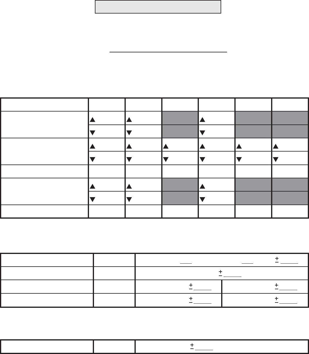
MODEL DATA RECORDING SHEET
MODEL DATA RECORDING SHEET
(Make copies before using)
Model name:
MENU FUNCTION
REVR Servo Reverse
D/R Dual Rate setting
EPA End Point Adjust
TRIM Trims
EXPO Exponential setting
F/S Failsafe (PCM Only)
CH 1 CH 2 CH 3 CH 4 CH 5 CH 6
N • R
Model No. 1 • 2 • 3 • 4 • 5 • 6
%
% % %
N • R
%
N • RN • R
%
%
% % %
% %
N • RN • R
%%%%%%
%%%%%%
%%%%%%
MIXING SETTING
PMIX Programmable Mixer
Flaperon
V-Tail
Elevon
INH • ON
FLPR INH • ON
V-TL INH • ON
ELVN INH • ON
Master Channnel
Ailerons differential rate %
Master Channnel Rate- %
CH 2 (Elevator) rate- %CH 4 (Rudder) rate- %
CH 1 (Aileron) rate- %CH 2 (Elevator) rate- %
FLAP TRIM SETTING
PLTR Flap Trim INH • ON Flap trim rate %

Flight packs
Flight packs
since your Futaba 6EXAP transmitter holds memories for up to six models, there is no need to purchase a
complete radio system (including the transmitter) for every model you fly. Available separately, Futaba Flight Packs contain a
receiver, servos, switch, battery and all servo mounting hardware. Consult your dealer or the Futaba Service Center for
specific contents and order numbers.
Receiver crystals:
Receiver crystals:
The receiver frequency may be changed as long as it remains within the “low” and “high” band frequency range. If your
receiver is on any channel from 11 through 35, it is a “low band” receiver and the frequency may be changed to any other
channel from 11 through 35 without having to perform any other service. Simply purchase a crystal on the desired channel,
then replace the existing crystal in your receiver with the new one. If your receiver is on any channel from 36 through 60, it is
a “high band” receiver and the frequency may be changed to any other channel from 36 through 60. To order a receiver
crystal, replace the “**” in the order numbers below with the required channel number. (To order a receiver crystal on channel
30, order FUTL5730.)
FM Dual Conversion 72 MHz low band
low band
(channels 11 - 35) receiver crystal . FUTL57**
FM Dual Conversion 72 MHz high band
high band
(channels 36 - 60) receiver crystal . FUTL58**
Note:
Note:
Should you ever wish to change the transmitter frequency, the transmitter must be sent to the Futaba Service Center for retuning.
FUTABA ACCESSORIES AND REPLACEMENT PARTS
FUTABA ACCESSORIES AND REPLACEMENT PARTS
(for USA)
(for USA)
REPLACEMENT PARTS
REPLACEMENT PARTS
ACCESSORIES
ACCESSORIES
ANT-5 Transmitter antenna.................................
NR-4J 4.8 Volt, 600 mAh receiver battery ..........
NT-8F 600B 9.6 Volt,
600 mAh Transmitter battery ..............................
FUTM5040
FUTM5040
FUTM1280
FUTM1280
FUTM1440
FUTM1440
SWH-13 Switch Harness w/charge plug .............
FSH-6X Servo arm..............................................
FSH-6S Servo arm..............................................
FSH-32 Servo mounting screws (10)..................
FUTM4370
FUTM4370
FUTM2030
FUTM2030
FUTM2010
FUTM2010
FUTM2250
FUTM2250
FTA-8 Neck strap ...............................................
NR-4K 4.8 Volt, 250 mAh receiver battery .........
NR-4B 4.8 Volt, 1,000 mAh receiver battery.......
NR-4F 4.8 Volt, 1,500 mAh receiver battery .......
AEC-3 8" [200mm] Servo Extension ..................
AEC-14 8" [200mm] Heavy Duty Servo Extension
(for digital servos) ...............................................
AEC-11 16" [400mm] Servo Extension ..............
AEC-15 16" [400mm] H.D. Servo Extension
(for digital servos) ...............................................
FUTM5692
FUTM5692
FUTM1210
FUTM1210
FUTM1380
FUTM1380
FUTM1285
FUTM1285
FUTM3910
FUTM3910
FUTM4140
FUTM4140
FUTM3955
FUTM3955
FUTM4145
FUTM4145
AEC-16 Dual H.D. Servo Extension
(Y-connector, for digital servos)...........................
AEC-13 Dual Servo Extension (Y-connector) .....
SR-10 Dual Servo Reverser ...............................
Trainer Box transmitter........................................
(if using with 6EXA transmitter use the MD-TC trainer cord)
MD-TC trainer cord .............................................
MM-TC trainer cord..............................................
FUTM4135
FUTM4135
FUTM4130
FUTM4130
FUTM4150
FUTM4150
FUTM4375
FUTM4375
FUTM4420
FUTM4420
FUTM4415
FUTM4415