User Manual
6-Channel Digital Proportional R/C System
1M23N32701
TM
INSTRUCTION MANUAL
2
Technical updates and additional programming examples available at: http://www.futaba-rc.com/faq
Entire Contents © 2017
TABLE OF CONTENTS
● Introduction ・・・・・・・・・・・・・・・・・・・・ 3
● Support and Service ・・・・・・・・・・・・・・・・・ 3
● Application, Export, and Modication ・・・・・・・・・ 4
● Denitions of Symbols ・・・・・・・・・・・・・・・ 6
● Precautions (do not operate without reading) ・・・・・ 6
● Features ・・・・・・・・・・・・・・・・・・・・・・ 9
● Contents ・・・・・・・・・・・・・・・・・・・・・・ 9
● System compatibility ・・・・・・・・・・・・・・・・ 9
● Transmitter controls ・・・・・・・・・・・・・・・ 10
● Receiver R3106GF ・・・・・・・・・・・・・・・・・ 11
● Installation of the Battery ・・・・・・・・・・・・・ 12
● Transmitter power ON/OFF (and fail-safe) ・・・・・・ 13
● Monitor LED ・・・・・・・・・・・・・・・・・・・ 13
● Stick control ・・・・・・・・・・・・・・・・・・・ 13
● Stick control : Airplane Example ・・・・・・・・・・ 14
● Trim ・・・・・・・・・・・・・・・・・・・・・・・ 15
● Channel-5・Switch ・・・・・・・・・・・・・・・・ 16
● Channel-6・Dial ・・・・・・・・・・・・・・・・・ 16
● Trainer function (Student only) ・・・・・・・・・・・ 16
● Link procedure ・・・・・・・・・・・・・・・・・・ 17
● Power down mode ・・・・・・・・・・・・・・・・ 18
● Servo reverse ・・・・・・・・・・・・・・・・・・・ 19
● Elevon mixing ・・・・・・・・・・・・・・・・・・ 20
● V-Tail mixing ・・・・・・・・・・・・・・・・・・・ 20
● Flaperon mixing ・・・・・・・・・・・・・・・・・ 21
● When a mixing isn't used (Normal) ・・・・・・・・・ 21
● Mounting the receiver switch ・・・・・・・・・・・ 22
● Safety precautions when you install receiver and servos 22
● Change to mode1 ・・・・・・・・・・・・・・・・・ 23
● Technical specications ・・・・・・・・・・・・・・ 24
3
INTRODUCTION
Thank you for purchasing a Futaba® T-FHSS Air-2.4GHz 6L Sport series digital proportional R/
C system. In order for you to make the best use of your system and to y safely, please read this
manual carefully. If you have any diculties while using your system, please consult the manual,
our online Frequently Asked Questions (on the web pages referenced below), your hobby dealer,
or the Futaba Service Center.
Due to unforeseen changes in production procedures, the information contained in this manual is
subject to change without notice.
Support and Service: It is recommended to have your Futaba equipment serviced annually during
your hobby’s “o season” to ensure safe operation.
IN NORTH AMERICA
Please feel free to contact the Futaba Service Center for assistance in operation, use and
programming. Please be sure to regularly visit the 6L Sport Frequently Asked Questions web site
at www.futaba-rc.com/faq/. This page includes extensive programming, use, set up and safety
information on the 6L Sport radio system and is updated regularly. Any technical updates and
US manual corrections will be available on this web page. If you do not nd the answers to your
questions there, please see the end of our F.A.Q. area for information on contacting us via email
for the most rapid and convenient response.
Don’t have Internet access? Internet access is available at no charge at most public libraries,
schools, and other public resources. We nd internet support to be a fabulous reference for many
modelers as items can be printed and saved for future reference, and can be accessed at any hour
of the day, night, weekend or holiday. If you do not wish to access the internet for information,
however, don’t worry. Our support teams are available Monday through Friday 8-5 Central time
to assist you.
FOR SERVICE ONLY:
Futaba Service Center
3002 N. Apollo Drive, Suite 1
Champaign, IL 61822
Phone: 217-398-0007
www.futaba-rc.com/service.html
Email: futabaservice@hobbico.com
FOR SUPPORT :
(PROGRAMMING AND USER
QUESTIONS)
Please start here for answers to most questions:
www.futaba-rc.com/faq/
Fax: 217-398-7721
Phone: 217-398-8970 option 2
OUTSIDE NORTH AMERICA
Please contact your Futaba importer in your region of the world to assist you with any questions,
problems or service needs.
Please recognize that all information in this manual, and all support availability, is based upon
the systems sold in North America only. Products purchased elsewhere may vary. Always contact
your region’s support center for assistance.
4
Compliance Information Statement
This device complies with part 15 of the FCC Rules. Operation is subject to the following three
conditions:
(1) This device may not cause harmful interference, and (2) This device must accept any
interference received, including interference that may cause undesired operation.
(3)RF Radiation Exposure Statement
This equipment complies with FCC radiation exposure limits set forth for an uncontrolled
environment.
This transmitter must not be co-located or operating in conjunction with any other antenna or
transmitter.
The responsible party for the compliance of this device is:
Futaba Service Center
3002 N Apollo Drive Suite 1, Champaign, IL 61822 U.S.A.
TEL (217)398-8970 or E-mail: support@hobbico.com (Support)
TEL (217)398-0007 or E-mail: futabaservice@hobbico.com (Service)
The RBRC. SEAL on the nickel-cadmium battery contained in Futaba products
indicates that Futaba Corporation is voluntarily participating in an industry-wide
program to collect and recycle these batteries at the end of their useful lives, when
taken out of service within the United States. The RBRC. program provides a
convenient alternative to placing used nickel-cadmium batteries into the trash or
municipal waste system, which is illegal in some areas.
(for USA)
You may contact your local recycling center for information on where to return the spent battery.
Please call 1-800-8BATTERY for information on NiCd battery recycling in your area. Futaba
Corporation involvement in this program is part of its commitment to protecting our environment
and conserving natural resources.
*RBRC is a trademark of the Rechargeable Battery Recycling Corporation.
Application, Export, and Modication
1. This product may be used for unmanned aerial vehicle use. It is not intended for use in any
application other than unmanned aerial vehicle control. The product is subject to regulations of
the Ministry of Radio/Telecommunications and is restricted under Japanese law to such purposes.
2. Exportation precautions:
(a) When this product is exported from the country of manufacture, its use is to be approved by
the laws governing the country of destination which govern devices that emit radio frequencies. If
this product is then re-exported to other countries, it may be subject to restrictions on such export.
Prior approval of the appropriate government authorities may be required. If you have purchased
this product from an exporter outside your country, and not the authorized Futaba distributor in
your country, please contact the seller immediately to determine if such export regulations have
been met.
(b) Use of this product with anything other than models may be restricted by Export and Trade
Control Regulations, and an application for export approval must be submitted. This equipment
must not be utilized to operate equipment other than radio controlled models.
3. Modication, adjustment, and replacement of parts: Futaba is not responsible for unauthorized
modication, adjustment, and replacement of parts on this product. Any such changes may void
the warranty.
5
Where to Fly
We recommend that you y at a recognized model airplane ying eld. You can nd model
clubs and elds by asking your nearest hobby dealer, or, in the US, by contacting the Academy
of Model Aeronautics.
The national Academy of Model Aeronautics (AMA) has more than 2,500 chartered clubs
across the country. Through any one of them, instructor training programs and insured
newcomer training are available. Contact the AMA at the address or toll-free phone number
below.
Academy of Model Aeronautics
5161 East Memorial Drive
Muncie, IN 47302
Tele. (800) 435-9262
Fax (765) 289-4248
or via the Internet at http:\\www.
modelaircraft.org
Always pay particular attention to the ying eld’s rules, as well as the presence and
location of spectators, the wind direction, and any obstacles on the eld. Be very careful
ying in areas near power lines, tall buildings, or communication facilities as there may be
radio interference in their vicinity.
CAUTION:
To assure continued FCC compliance:
Any changes or modications not expressly approved by the grantee of this device could void the
user's authority to operate the equipment.
No. Name Gain(Peak) Remark
1 Internal pattern 2.14dBi 1/2 λ pattern type antenna
NOTE:
This device complies with Industry Canada license-exempt RSS standard(s). Operation is subject
to the following two conditions: (1) this device may not cause interference, and (2) this device
must accept any interference, including interference that may cause undesired operation of the
device.
This equipment complies with IC radiation exposure limits set forth for an uncontrolled
environment. This transmitter must not be co-located or operating in conjunction with any other
antenna or transmitter.
French: Cet appareil radio est conforme au CNR-210 d’Industrie Canada. L’utilisation de ce
dispositif est autorisée seulement aux deux conditions suivantes : (1) il ne doit pas produire de
brouillage, et (2) l’utilisateur du dispositif doit être prêt à accepter tout brouillage radioélectrique
reçu, même si ce brouillage est susceptible de compromettre le fonctionnement du dispositif. Cet
équipement est conforme aux limites d'exposition au rayonnement du CI établies pour un
environnement non contrôlé. Cet émetteur ne doit pas être co-situé ou fonctionner conjointement
avec une autre antenne ou émetteur.
This radio transmitter has been approved by Industry Canada to operate with the antenna types
listed below with the maximum permissible gain indicated. Antenna types not included in this
list, having a gain greater than the maximum gain indicated for that type, are strictly prohibited
for use with this device.
6
Precautions
Application, Export, and Modification Precautions.
1. This product is only designed for use with radio control models. Use of the product described in this instruction
manual is limited to radio control models.
2. Export precautions:
a) When this product is exported, it cannot be used where prohibited by the laws governing radio waves of the
destination country.
b) Use of this product with other than models may be restricted by Export and Trade Control Regulations.
3. Modification, adjustment, and parts replacement
Futaba is not responsible for unauthorized modification, adjustment, or replacement of parts on this product.
■ No part of this manual may be reproduced in any form without prior permission.
■ The contents of this manual are subject to change without prior notice.
■ The contents of this manual should be complete, but if there are any unclear or missing parts please contact a
Futaba Service Center.
■ Futaba is not responsible for the use of this product by the customer.
■ Company and product names in this manual are trademarks or registered trademarks of the respective company.
Flying Precautions
WARNING
Never grasp the built-in transmitter antenna
while ying.
■ The transmitter output may drop drastically.
Always make sure that all transmitter stick
movements operate all servos properly in the
model prior to flight. Also, make sure that all
switches, etc. function properly as well. If there
are any diculties, do not use the system until all
inputs are functioning properly.
Never y in range check mode.
■ In the dedicated range test range check mode, the
transmitter output range is reduced and may cause a
crash.
While operating, never touch the transmitter
with, or bring the transmitter near, another trans-
mitter, a cellphone, or other wireless devices.
■ Doing so may cause erroneous operation.
For safe use
Please observe the following precautions to ensure safe use of this product at all times.
Meaning of Special Markings:
The parts of this manual indicated by the following marks require special attention from the standpoint of safety.
DANGER - Procedures which may lead to dangerous conditions and cause death/serious injury if not carried out properly.
WARNING - Procedures which may lead to a dangerous condition or cause death or serious injury to the user if not carried
out properly, or procedures where the probability of supercial injury or physical damage is high.
CAUTION - Procedures where the possibility of serious injury to the user is small, but there is a danger of injury, or
physical damage, if not carried out properly.
= Prohibited = Mandatory
WARNING: Always keep electrical components away from small children.
Never fly on a rainy day, when the wind is
strong or at night.
■ Water could lead to failure or improper functionality
and poor control of the aircraft which could lead to a
crash.
Never turn the power switch off during flight
or while the engine or motor is running.
■ Operation will become impossible and the aircraft will
crash. Even if the power switch is turned on, operation will
not begin until transmitter and receiver internal process-
ing is complete.
Do not start the engine or motor while wearing
the neck strap.
■ The neck strap may become entangled with the rotat-
ing propeller, rotor, etc. and cause serious injury.
Do not y when you are physically impaired as
it could pose a safety hazard to yourself or others.
7
Do not y at the following places:
■ Near another radio control ying eld.
■ Near or above people.
■ Near homes, schools, hospitals or other places where
people congregate.
■ Near high voltage lines, high structures, or communi-
cation facilities.
When setting the transmitter on the ground
during flight preparations, do not stand it
upright.
■ The transmitter may tip over, the sticks may move and
the propeller or rotor may rotate unexpectedly and cause
injury.
Do not touch the engine, motor, or FET amp
during and immediately after use.
■ These items may become hot during use.
For safety, y so that the aircraft is visible at all
times.
■ Flying behind buildings or other large structures will
not only cause you to lose sight of the aircraft, but also
degrade the RF link performance and cause loss of control.
From the standpoint of safety, always set the
fail safe function.
■ In particular, normally set the throttle channel to idle.
Always check the remaining capacity of the
transmitter and receiver batteries before each
ying session prior to ight.
■ Low battery capacity will cause loss of control and a crash.
Always check operation of each control surface
and perform a range test before each flying
session. Also, when using the trainer function,
check the operation of both the teacher and
student transmitter.
■ Even one incorrect transmitter setting or aircraft abnor-
mality can cause a crash.
Before turning on the transmitter:
1. Always move the transmitter throttle stick position to
the minimum (idle) position.
2. Turn on the transmitter rst and then the receiver.
When turning off the transmitter's power
switch. After the engine or motor has stopped
(state in which it will not rotate again):
1. Turn o the receiver power switch.
2. Then turn o the transmitter power switch.
■ If the power switch is turned on/off in the opposite
order, the propeller may rotate unexpectedly and cause a
serious injury.
■ Also always observe the above order when setting the
fail safe function.
■ Maximum low throttle: Direction in which the engine
or motor runs at the slowest speed or stops.
When adjusting the transmitter, stop the
engine except when necessary. In the case of a
motor, disconnect the wiring and don't allow it
to continue operation. When doing so, please
exercise extreme caution. Ensure that the aircraft
is secured and that it will not come into contact
with anything or anyone. Ensure that the motor
will not rotate prior to making any adjustments.
■ Unexpected high speed rotation of the engine may
cause a serious injury.
Battery and Charger Handling Precautions
DANGER
Do not recharge a battery that is damaged,
deteriorated, leaking electrolyte, or wet.
Do not use the charger in applications other
than as intended.
Do not allow the charger or battery to become
wet.
■ Do not use the charger, when it or your hands, are wet.
Do not use the charger in humid places.
Do not short circuit the battery.
Do not solder, repair, deform, modify, or disas-
semble the battery and/or battery charger.
Do not drop the battery into a fire or bring it
near a re.
Do not charge and store the battery in direct
sunlight or other hot places.
Do not charge the battery if it is covered with
any object as it may become very hot.
Do not use the battery in a combustible envi-
ronment.
■ The combustibles may ignite and cause an explosion
or re.
Always charge the battery before each flying
session.
■ If the battery goes dead during ight, the aircraft will
crash.
Always use the charger with the specified
power supply voltage.
■ Use the special charger by connecting it to a proper
power outlet.
If the battery liquid should get in your eyes,
do not rub your eyes, but immediately wash
them with tap water or other clean water and get
treated by a doctor.
■ The liquid can cause blindness.
8
Do not touch the charger and battery for any
length of time during charging.
■ Doing so may result in burns.
Do not use a charger or battery that has been
damaged.
If any abnormalities such as smoke or
discoloration are noted with either the charger or
the battery, remove the battery from the charger
and disconnect the power cord plug and do not
use the charger.
■ Continued use may cause re, combustion, generation
of heat, or rupture.
Do not subject the batteries to impact.
■ Doing so may cause fire, combustion, generation of
heat, rupture, or liquid leakage.
WARNING
If the battery leaks liquid or generates an
abnormal odor, immediately move it to a safe
place for disposal.
■ Not doing so may cause combustion.
If the battery liquid gets on your skin or
clothing, immediately flush the area with tap
water or other clean water.
■ Consult a doctor. The liquid can cause skin damage.
After the specified charging time has elapsed,
end charging and disconnect the charger from the
receptacle.
When recycling or disposing of the battery,
isolate the terminals by covering them with
cellophane tape.
■ Short circuit of the terminals may cause combustion,
generation of heat or rupture.
Do not place heavy objects on top of the
battery or charger. Also, do not place the battery
or charger in any location where it may fall.
■ Doing so may cause damage or injury.
Do not store or use the battery and charger
where it is dusty or humid.
■ Insert the power cord plug into the receptacle only
after eliminating the dust.
CAUTION
Do not charge the battery in extreme temperatures.
■ Doing so will degrade the battery performance. An
ambient temperature of 10℃ to 30℃ (50 ℉ to 86 ℉ ) is
ideal for charging.
Unplug the charger when not in use.
Do not bend or pull the cord unreasonably and
do not place heavy objects on the cord.
■ The power cord may be damaged and cause combus-
tion, generation of heat, or electric shock.
Do not directly expose plastic parts to fuel, oil,
exhaust gas, etc.
■ If left in such an environment, the plastic may be dam-
aged.
■ Since the metal parts of the case may corrode, always
keep them clean.
Join the Academy of Model Aeronautics.
■ The Academy of Model Aeronautics (AMA) provides
guidelines and liability protection should the need arise.
Other Precautions
CAUTION
Storage and Disposal Precautions
Do not store wireless devices in the following
places:
・ Where it is extremely hot (40℃ [104F] or higher) or
cold (-10℃ [14F] or lower)
・ Where the equipment will be exposed to direct sun-
light
・ Where the humidity is high
・ Where vibration is prevalent
・ Where it is very dusty
・ Where the device may be exposed to steam and heat
CAUTION
When the device will not be used for a long
time, remove the battery from the transmitter
and aircraft and store them in a dry place where
the temperature is between 0 and 30℃ [32F and
86F].
■ When left 'as is', batteries may deteriorate, leak, or be
otherwise damaged.
Always use genuine Futaba products such as
transmitter, receiver, servo, FET amplier, battery,
etc.
■ Futaba is not responsible for damage sustained by
combination with parts other than Futaba Genuine Parts.
Use the parts specified in the instruction manual and
catalog.
9
T6L Sport transmitter
R3106GF receiver
FEATURES
CONTENTS
● Transmitter T6L Sport
● Receiver R3106GF
● Instruction manual
SYSTEM COMPATIBILITY
● T-FHSS Air (Mono directional)-2.4GHz 6-channel transmitter
The Futaba 2.4GHz T-FHSS Air system is employed. (*No telemetry)
● Built-in antenna
Antenna built into the transmitter provides a simple appearance and improves handling ease.
● Power-saving type transmitter
Four AA alkaline batteries can be used.
● Mixing type selection
Elevon, V-Tail, and Flaperon mixing type can be selected to match the aircraft type.
● Trainer function (Student only)
The T6L Sport trainer function lets you practice ying as a student by connecting the T6L Sport to the
instructor’s Futaba transmitter.
● AUX Channel 5 switch function
● AUX Channel 6 dial function
● T-FHSS Air (Mono directional)-2.4GHz 6-channel receiver
The Futaba 2.4GHz T-FHSS Air system is employed. (*No telemetry)
● Fail Safe function (Throttle channel <ch3> only)
The Fail Safe function is recommended to use for safety reasons in the event of radio interference.
The “F/S” (Fail Safe) function moves the throttle servo to a predetermined position.
The T6L uses Futaba's 2.4GHz T-FHSS Air transmission system. The compatible receivers are shown below.
NOTE:
*The Futaba T-FHSS Air system cannot be used with Futaba S-FHSS/FASST/FASSTest systems. Use
it with a T-FHSS Air system transmitter and receiver. However, the telemetry system cannot be used.
*The T-FHSS Air system and T-FHSS surface system are dierent. The T6L cannot be used with the
R304SB,R304SB-E,R314SB,R314SB-E or T-FHSS surface system receivers.
Communications System Usable Receivers
T-FHSS Air R3006SB, R3008SB, R3001SB
*R304SB,R304SB-E,R314SB,R314SB-E,T-FHSS
surface system receivers do not operate.
10
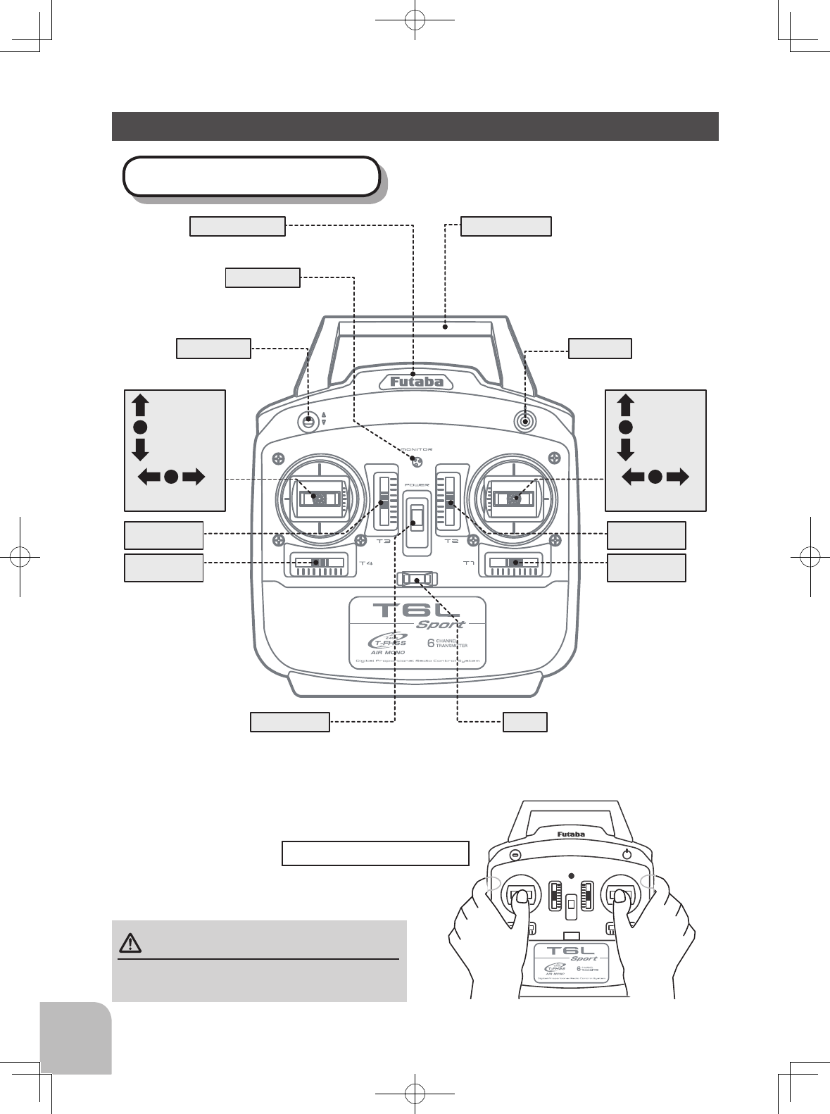
TRANSMITTER CONTROLS-T6L Sport (in case of mode 2)
Transmitter T6L Sport
Carrying handle
CH5 Switch
Built-in Antenna
Monitor LED
CH6 Dial
Rudder
Stick
Throttle
Stick
Throttle
Trim lever
Rudder
Trim lever
Elevator
Trim lever
Aileron
Trim lever
Aileron
Stick
Elevator
Stick
Power Switch
(Up position: ON)
Hook
(for optional neckstrap)
How to hold the transmitter
・When operating the dial or the switch, be careful
not to drop the transmitter.
CAUTION
11
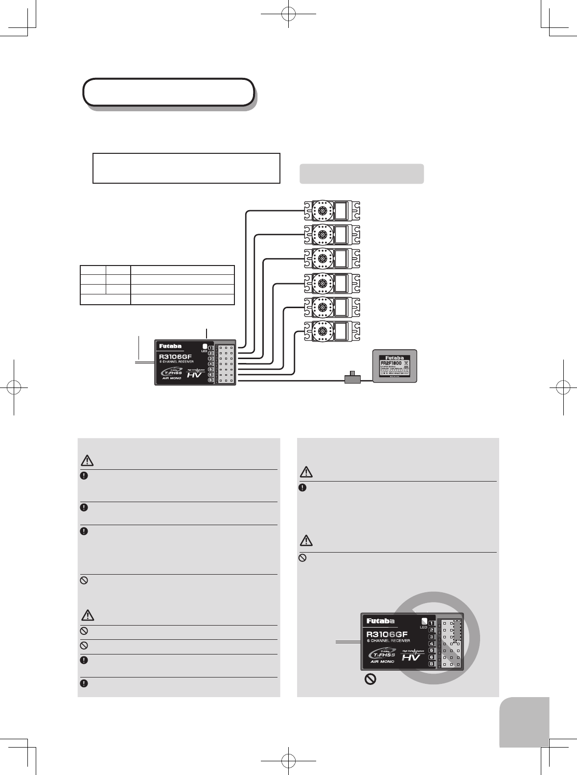
Receiver R3106GF
The R3106GF receiver has 6 PWM channel outputs.
(Note: When power is supplied
from a motor controller, a separate
power supply is not required.)
LED
3︓Throttle servo (engine)
3︓Motor controller (electric)
Battery
Switch
1︓Aileron servo
2︓Elevator servo
4︓Rudder servo
6︓2nd Aileron servo(Flaperon)
6︓Flap servo
5︓Gear servo
Antenna
R3106GF is T-FHSS Air system, but the
telemetry function isn't equipped.
Receiver installation precaution
WARNING
The R3106GF receiver should be protected from vi-
bration by foam rubber, hook and loop tape, or similar
mounting methods. Protect from moisture.
Keep away from conductive materials to avoid short
circuits.
Be sure that the battery is the correct size for the
amount and type of servos being used. When using a
BEC, be sure that it is capable of delivering constant
voltage and can accept enough current that will be
used by the RX and servos.
Do not use a dry cell battery with this receiver.
Antenna installation precaution
WARNING
Don't cut or bundle the receiver antenna wire.
Don't bend the coaxial cable. It causes damage.
The antennae must be installed in a way that
ensures they are not under strain.
Keep the antenna as far away from the motor, ESC
and other noise sources as you possibly can.
Antenna installation for carbon
fuselage
WARNING
You must leave 30mm at the tip of the antenna fully
exposed. The exposed antenna should be secured
so that it cannot move around or back inside of your
aircraft.
Connect precaution
DANGER
Don't connect a connector, as shown next.
• The connector will short circuit if it is connected in this
way. A short circuit across the battery terminals may
cause abnormal heat and possibly re.
Connection example
LED Indication
Green Red Status
Off Solid No signal reception
Solid Off Receiving signals
Alternate blink Unrecoverable error (EEPROM, etc.)
Receiver
Do not insert either a switch
or battery in this manner.
12
①②
④⑤
③
Pay very close attention to the polarity
markings and insert accordingly.
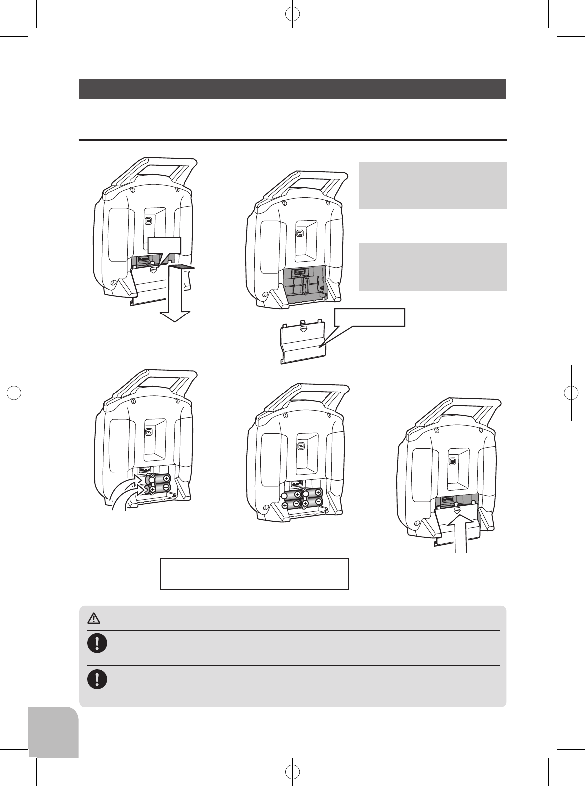
INSTALLATION OF THE BATTERY
Slide the battery cover o the
transmitter in the direction of
the arrow in the gure.
Slide the battery cover
back onto the case.
Load the new AA size
batteries.
Push
Battery Cover
The T6L Sport transmitter is designed to work with four (4) AA alkaline dry cell batteries. AA alkaline
batteries are available at any local hobby shop or grocery store and need to be purchased separately.
CAUTION
Always be sure you reinsert the batteries in the correct polarity order.
If the batteries are loaded incorrectly, the transmitter may be damaged.
Remove the batteries whenever the transmitter will not be in use. If the batteries
do happen to leak, clean the battery case and contacts thoroughly. Make sure the
contacts are free of corrosion.
Check:
Turn the power switch on the transmitter
to the ON position. Check the display on
the monitor LED. If the LED is blinking
or OFF, check the batteries for insucient
contact or incorrect battery polarity.
Disposal of the Dry Cell Batteries:
The method to dispose of used dry cell
batteries depends on the area in which
you reside. Dispose of the batteries in
accordance with the regulations for your
area.
13
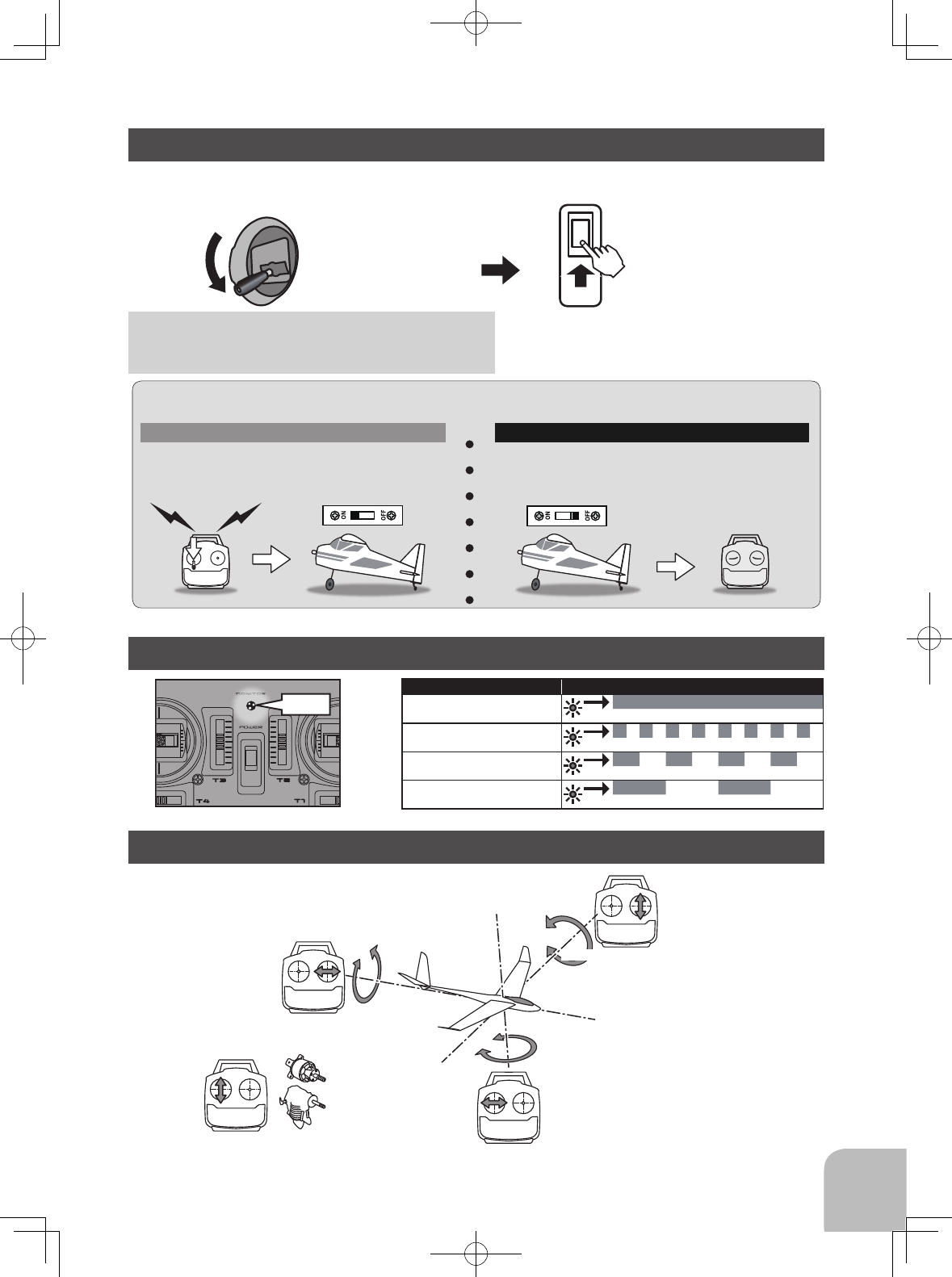
The throttle position when turning on a receiver
power supply will be a fail-safe position. The throttle
moves to this (low) position in an emergency.
TRANSMITTER POWER ON/OFF (Fail safe setting)
MONITOR LED STATE
STICK CONTROL
Throttle Stick Low
(F/S position) ON the Power Switch
1. Throttle stick to the low (F/S) position.
2. Turn on the transmitter power switch.
3. Turn on the receiver or motor controller switch.
Always be sure the motor/engine is stopped.
1. Turn o the receiver or motor controller switch.
2. Then turn o the transmitter power switch.
ON OFF
OFF
ON
THR LOW
Turning on the power switches
If the power switches are turned o in the opposite order, the model may unexpectedly run out of control and
cause a very dangerous situation.
Turning o the power switches
When turning on the power of the transmitter. The status of the transmitter is displayed by the LED at the
upper part of the front of a transmitter.
Status LED
ON Solid
Low Battery Once 0.25s ON - Once 0.25s OFF
Power Down Mode Once 0.5s ON - Once 0.5s OFF
Link Mode Once 1s ON - Once 1s OFF
Yawing axis
Pitching axis
Elevator Stick
Aileron stick
Throttle stick
Engine/motor
Power
Rudder stick
Roll axis
*Example Stick Mode 2
LED
14
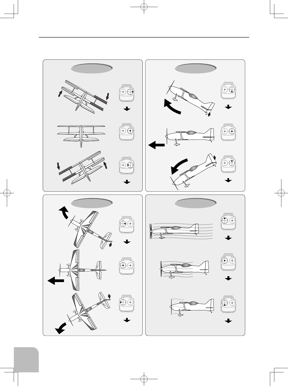
Stick control : Airplane Example
A general model example. (It depends on each plane types.)
Right roll
Left roll
Straight
The rudder is
right.
The rudder is
left.
The left aileron
is down.
The left aileron
is up.
Level flight Level flight
The right aileron
is up.
The right
aileron is
down.
Elevator is up.
Elevator is down.
Aileron stick
To the right
Neutral Neutral
Nose Up
Nose Down
Middle
High
Low
Roll axis Control
Yaw axis Control Throttle Control
Elevator stick
UP
(moved to the bottom)
Elevator stick
DOWN
(moved to the top)
Aileron stick
To the left
Pitch axis Control
Rudder stick
To the right
Neutral
Rudder stick
To the left
Nose Right
Nose Left
Throttle stick
MIDDLE
(neutral)
Throttle stick
HIGH
(moved to the top)
Throttle stick
LOW
(moved to the bottom)
*Example Stick Mode 2
15
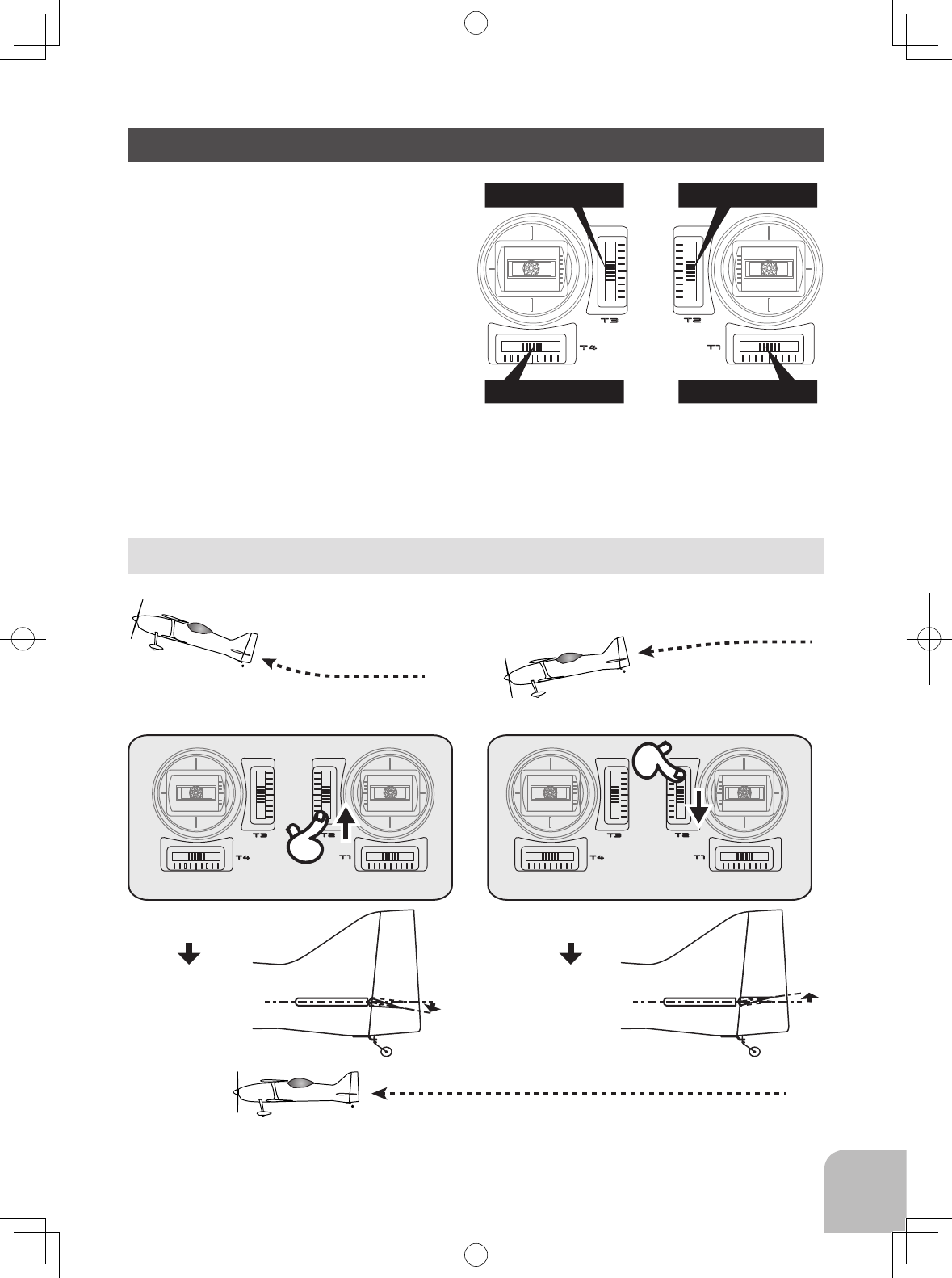
There are four trim levers (“trims”) on the front of
the transmitter. These trims are for adjusting the
neutral position of the aileron, elevator and rudder
servos and for setting the idle r.p.m. of the engine
when the throttle stick is all the way down. The
intended use of the trims is to make small servo
adjustments, in flight, to get the model properly
“trimmed” (so it will fly straight-and-level).
Simply push or pull on the trim levers while ying
and the neutral position of the servos will shift.
Keep in mind that you should start out with the
control surfaces centered when the servos are
centered and the trims are “zeroed” (or near zero).
Trim operational example
CH1 Aileron Trim
CH2 Elevator Trim
CH4 Rudder Trim
CH3 Throttle Trim
TRIM
Elevator neutral
Down
◆When the airplane goes up while the
elevator stick is neutral.
◆When the airplane dives while the
elevator stick is neutral.
◆Adjust so that the airplane flies level.
Elevator neutral
Up
◆Elevator trim to up
◆Elevator trim to down
*Example Stick Mode 2
16
The T6L Sport-2.4GHz trainer function lets you practice ying as a student
by connecting the T6L Sport-2.4GHz to the instructor’s Futaba transmitter.
To utilize the trainer function, the appropriate trainer cord (available
separately) and a second Futaba transmitter (usually provided by your ight
instructor or R/C club) will be required. When two radios are connected
with the trainer cord, they are both capable of operating the model, but it's
usually best for the instructor to hold the radio that has been setup for the
plane to be own (as it is already programmed to y the model). When the
instructor holds the trainer switch on his radio, the student will have control.
When the instructor wishes to regain control he simply releases the switch.
Then he will have immediate, full control.
Power application isn't done from teacher's transmitter. Student's T6L Sport
also turns on a power supply.
Trainer cord available separately
TRAINER FUNCTION (Student only)
CHANNEL 5 SWITCH
CHANNEL 6 DIAL
CH6
This switch operates the servo connected to channel 5 in the
receiver. If your model has retractable landing gear, this is the
control used to extend and retract the gear.
This dial operates the servo connected to channel six in the
receiver. If your model is equipped with flaps, this is the
control used to operate them.
Movement of channel 5 is only simple on - o.
CH5
17
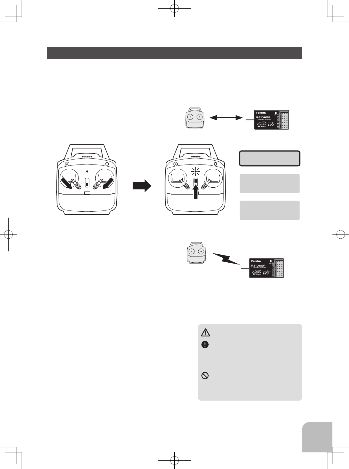
LINK PROCEDURE
1 Place the transmitter and the receiver
close to each other within 20 inches (half
meter).
2 To activate the "Link Mode".
3 Immediately turn on the receiver power.
The receiver will enter the linking state
(LED blinks red) about 3 seconds after
the receiver power is turned on.
4 The LED changed from red to a steady green light, linking is complete.
(A linking process is ended in 15 seconds.)
5 Check system operation. If the transmitter and receiver are not linked, try linking again.
Less than 20 inches
In "Link" Mode
Receiver ON
Operate both sticks fully in the
bottom and the inside, in the
power o state.
Turn on the power switch.
Transmitter in
"Link Mode"
Transmitter LED blinking
Once 1s ON - Once 1s OFF
Enters the link mode
for 15 seconds
Each transmitter has an individually assigned, unique ID code. In order to start operation, the
receiver must be linked with the ID code of the transmitter with which it is being paired. Once
the link is made, the ID code is stored in the receiver and no further linking is necessary unless
the receiver is to be used with another transmitter. When you purchase additional receivers, this
procedure is necessary; otherwise the receiver will not work.
WARNING
After the linking is done, please cy-
cle receiver power and check that
the receiver to be linked is really un-
der the control of the transmitter.
Don't perform the linking procedure
with motor's main wire connected or
with the engine operating as it may
result in serious injury.
*If there are many T-FHSS Air systems turned on in close
proximity, your receiver might have diculty establishing a link
to your transmitter. This is a rare occurrence. However, should
another T-FHSS Air transmitter/receiver be linking at the same
time, your receiver could link to the wrong transmitter. This is
very dangerous if you do not notice this situation. In order to
avoid the problem,we strongly recommend you double check
whether your receiver is really under control by your transmitter.
* The R3106GF uses the T-FHSS Air (Mono directional) system
so if used with another T-FHSS Air transmitter, then the ID of
the R3106GF receiver will not be shown on the transmitter's dis-
play. A "NO LINK" indication or the ID of a previously linked
T-FHSS Air receiver will be shown. Nevertheless, if the LED
on the R3106GF displays a steady green light it is linked with a
transmitter. (Telemetry can not be used on the R3106GF.)
18
POWER DOWN MODE
A range check must be performed before the rst ight of a new model. It is not necessary to do
a range check before every ight (but is not a bad idea to perform a range check before the rst
ight of each day). A range check is the nal opportunity to reveal any radio malfunctions, and to
be certain the system has adequate operational range.
We have installed a special “Power Down Mode” in the T6L Sport in order to perform an
operational ground range check. During this mode, the RF power is reduced in order to test the
operational range of the T6L Sport.
DANGER
NEVER start flying when the "Power Down Mode" is
active.
*Control is impossible and your model will crash.
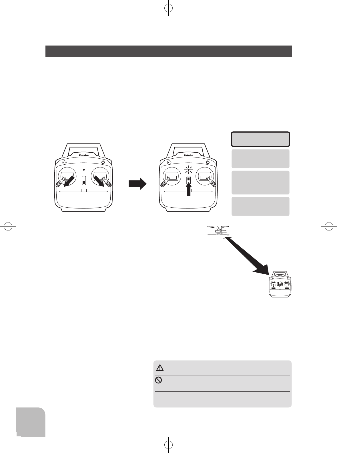
To activate the power down mode and perform a range check:
1 To activate the "Power Down Mode"
2 With the "Power Down Mode" activated, walk away from
the model while simultaneously operating the controls.
(Keep the throttle stick low.) Have an assistant stand by the
model and signal what the controls are doing to confirm
that they operate correctly. You should be able to walk
approximately 10m (33ft) from the model without losing
control.
3 If everything operates correctly, return to the model. Set
the transmitter in a safe, yet accessible location so it will be
within reach after starting the engine. Be certain the throt-
4 NEVER start ying in the Power Down mode. To be safe, cycle the power o then back on
when ready to y.
In "Power Down" Mode
keep the throttle stick
low.
walk approximately
10m (33ft)
Operate both sticks fully in the
bottom and the inside, in the
power o state.
Turn on the power switch.
Transmitter in
"Power down Mode"
Transmitter LED blinking
Once 0.5s ON - Once 0.5s OFF
Keep the throttle stick
low. If the throttle stick
is up, power down mode
will stop.
Enters the link mode
for 90 seconds
tle stick is all the way down, then start the engine. Perform another range check with your
assistant holding the plane and the engine running at various speeds. If the servos jitter
or move inadvertently, there may be a problem. Do not y the plane! Look for loose servo
connections or binding pushrods. Also be certain that the battery has been fully charged.
19
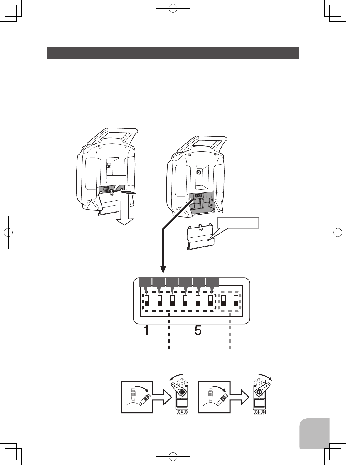
SERVO REVERSING
①②
④⑤
③
CH1 CH3 CH5CH2 CH4 CH6
The servo reverse switches are used to change the direction that a servo responds to a control
input from the transmitter (each stick). After using the reversing function, check all the controls
on the model to be certain they are operating in the correct direction and that you did not
inadvertently reverse a servo other than the one intended. Reversing the wrong servo (and not
checking the response of the controls before each ight) may be the most common cause of a
crash!
*Note that the direction of the aileron servo is easily mistaken.
Slide the battery cover o the
transmitter in the direction of
the arrow in the gure.
CH1-6 Reverse Switch Mixing Switch
Push
Battery Cover
20
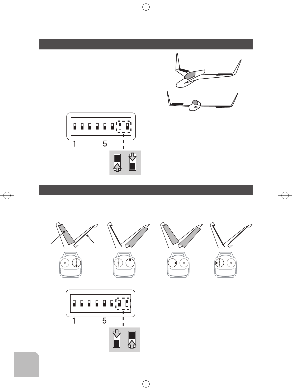
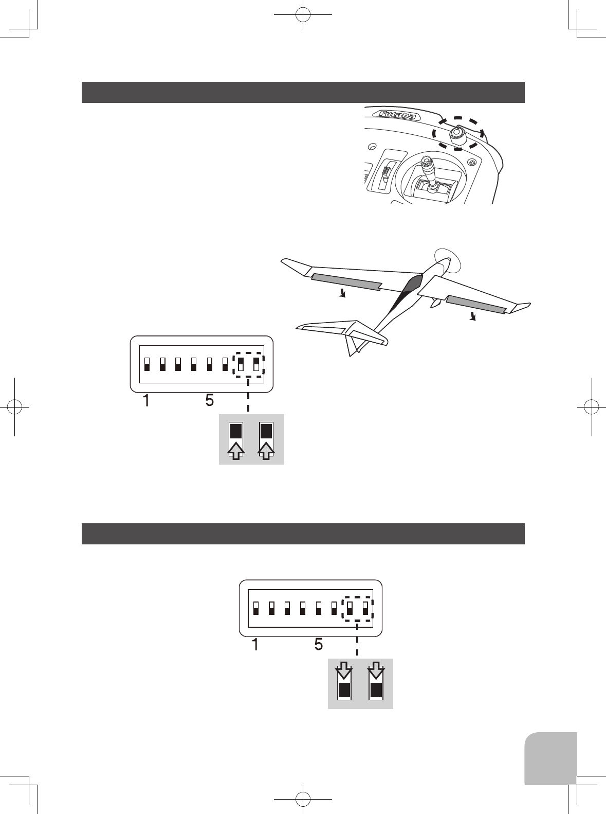
ELEVON MIXING
V-TAIL MIXING
7th switch, the top
8th switch, the bottom
7th switch, the bottom
8th switch, the top
CH1
CH1
CH2
CH2
Elevator
Aileron
CH4 (CH2)
Intended for tailless, “ying wing” models such as delta
wings and ying wings, elevon mixing mixes channel
1 (aileron) to channel 2 (elevator) allowing the elevons
to operate in unison (as elevators) or in opposition (as
ailerons). This function requires that each elevon be
operated by a separate servo.
* If necessary, use the Servo Reversing function to
achieve the correct direction of servo throws.
* If necessary, use the Servo Reversing
function to achieve the correct direction
of servo throws.
This mixing is used with V tail aircraft that
combine the elevator and rudder functions.
Elevator UP Elevator DOWN Rudder Right Rudder Left
(Stick mode 2)
CH2 (CH4)
21
7th switch, the top
8th switch, the top
7th switch, the bottom
8th switch, the bottom
FLAPERON MIXING
When a mix is not used(NORMAL)
Dial operation
2 ailerons are down in
same. (Up in same)
The ability to use separate servos to function in the
same movement direction to control the ap deection
and to work in opposing directions as ailerons is known
as flaperons. Again, this function allows the ailerons
to be used both as ailerons and as flaps. Flap control
is assigned to Channel 6, the proportional Dial on the
front of the transmitter. As such, if flaps are desired,
Channel 6 must be used as the additional aileron/flap
channel. Ailerons are controlled, of course, by the
aileron stick accordingly.
*If necessary, use the Servo Reversing
function to achieve the correct
direction of the servo throws.
22
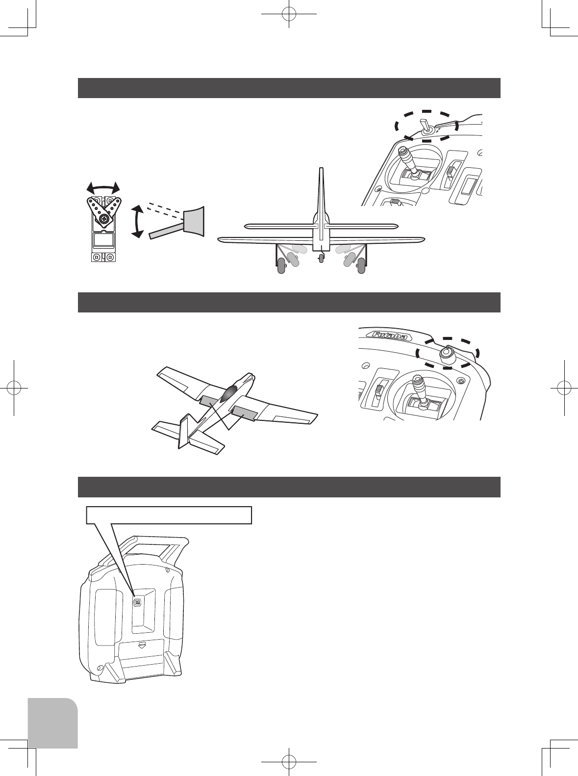
MOUNTING THE RECEIVER SWITCH
SAFETY PRECAUTIONS when you install receiver and servos
Connecting connectors
Be sure to insert the connector until it stops at the deepest point.
How to protect the receiver from vibration and water
Wrap the receiver with something soft such as foam rubber to avoid vibration. If there is a chance
of getting wet, put the receiver in a waterproof bag or balloon to avoid water.
Servo throw
Adjust your system so that pushrods will not bind or sag when operating the servos to the full
extent.
*If excessive force is continuously applied to a servo, the servo could be damaged due to force on the gear train
and/or power consumption causing rapid battery drain.
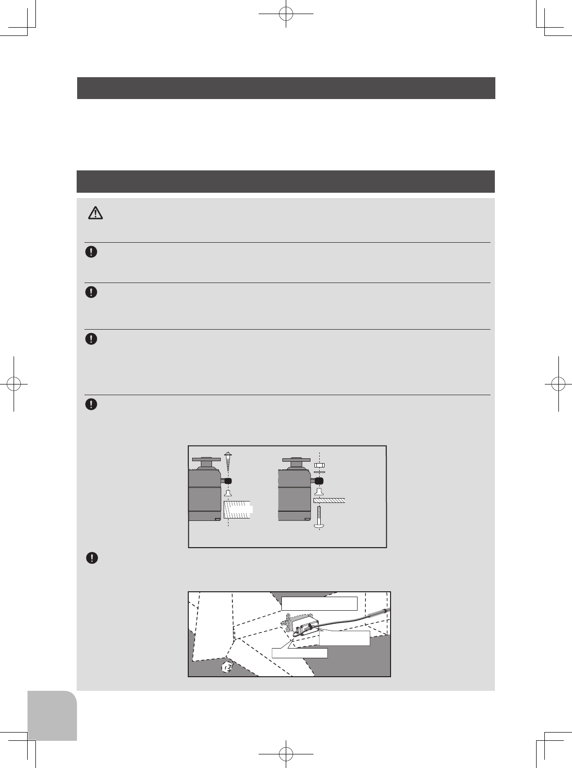
Mounting servos
Use a vibration-proof rubber (such as rubber grommet) under a servo when mounting the servo
on a servo mount. And be sure that the servo cases do not touch directly to the metal parts such
as servo mount.
*If the servo case contacts the airframe directly, vibration will travel to and possibly damage the servo.
Rubber
grommet
Brass eyelet
Wood screw
Servo mount
2.3-2.6mm nut
washer
Rubber
grommet
Brass eyelet
Servo mount
2.3-2.6mm screw
(Helicopter) (Airplane/Glider)
Servo lead wires
To prevent the servo lead cable from being broken by vibration during ight, provide a little slack in the
cable and fasten it at suitable points. Periodically check the cable during daily maintenance.
When mounting a power switch to an airframe, make a rectangular hole that is a little larger than
the total stroke of the switch so that you can turn the switch ON/OFF without binding.
Avoid mounting the switch where it can be covered by engine oil and dust. In general, it is
recommended to mount the power switch on the side of the fuselage that is opposite the muer.
WARNING
The fixed example of a lead wire
(inside of the fuselage)
Margin in the lead wire.
Wiring is softly fixed
to a servo.
23
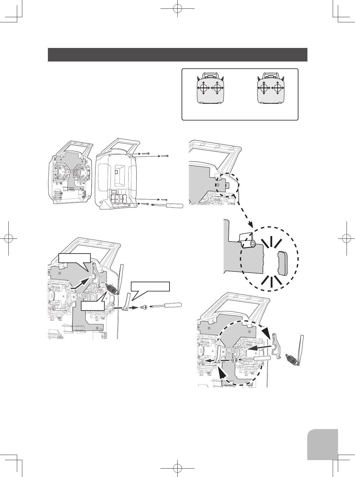
CHANGE TO MODE 1
The following sequence illustrates how to
change the T6L from 'Mode 2' into 'Mode 1'.
The ratchet mechanism must be changed to
the other side. This can be dicult to perform
so if in doubt please contact your local Futaba
Service center.
2 Remove the four transmitter rear case
screws and remove the rear case. 3 This part is cut.
4 Remove the ratchet plate /swing
arm/spring on the gimbal section.
5 Change the ratchet plate /swing arm/
spring on the gimbal section.
6 Install the rear case.
1 Open the battery cover on the back of the
transmitter and remove the transmitter battery.
THRELE
RUD AIL
MODE 1
ELETHR
RUD AIL
MODE 2
THRELE
AIL RUD
MODE 3
ELETHR
AIL RUD
MODE 4
Ratchet plate
Swing arm
Spring
24
TECHNICAL SPECIFICATIONS
Transmitter T6L Sport
2-stick, 6-channel, T-FHSS Air (Mono directional)-2.4G system
Transmitting frequency: 2.4GHz band
System: T-FHSS Air (Mono directional), No telemetry
Power supply: 6.0V Dry battery
Receiver R3106GF
T-FHSS Air
(Mono directional)
-2.4G system, No telemetry
Power requirement: 4.8V-7.4V battery or regulated output from ESC, etc. (*1)
Size: 1.7 x 0.98 x 0.35 in. (43.1 x 25.0 x 8.8 mm)
Weight: 0.3 oz. (7.8g)
(*1) When using ESC's make sure that the regulated output capacity meets your usage application.
FUTABA CORPORATION
1080 Yabutsuka, Chosei-mura, Chosei-gun, Chiba-ken, 299-4395, Japan
Phone: +81 475 32 6982, Facsimile: +81 475 32 6983
2017, 2 (1)
Compliance Information Statement (for EU)
Declaration of Conformity
Hereby, Futaba Corporation declares that the radio equipment type T6L Sport is in
compliance with Directive 2014/53/EU.
The full text of the EU declaration of conformity is available at the following
internet address:
http://www.rc.futaba.co.jp/english/dl/declarations.html