Futaba T7C-72 Radio Control Transmitter User Manual 7C manual low resolution
Futaba Corporation Radio Control Transmitter 7C manual low resolution
UserManual.wiki
>
Futaba
>
T7C 72 User Manual
User Manual
Navigation menu
Upload a User Manual
Namespaces
Wiki Guide
HTML
PDF
Info
Views
User Manual
Discussion / Help
Navigation
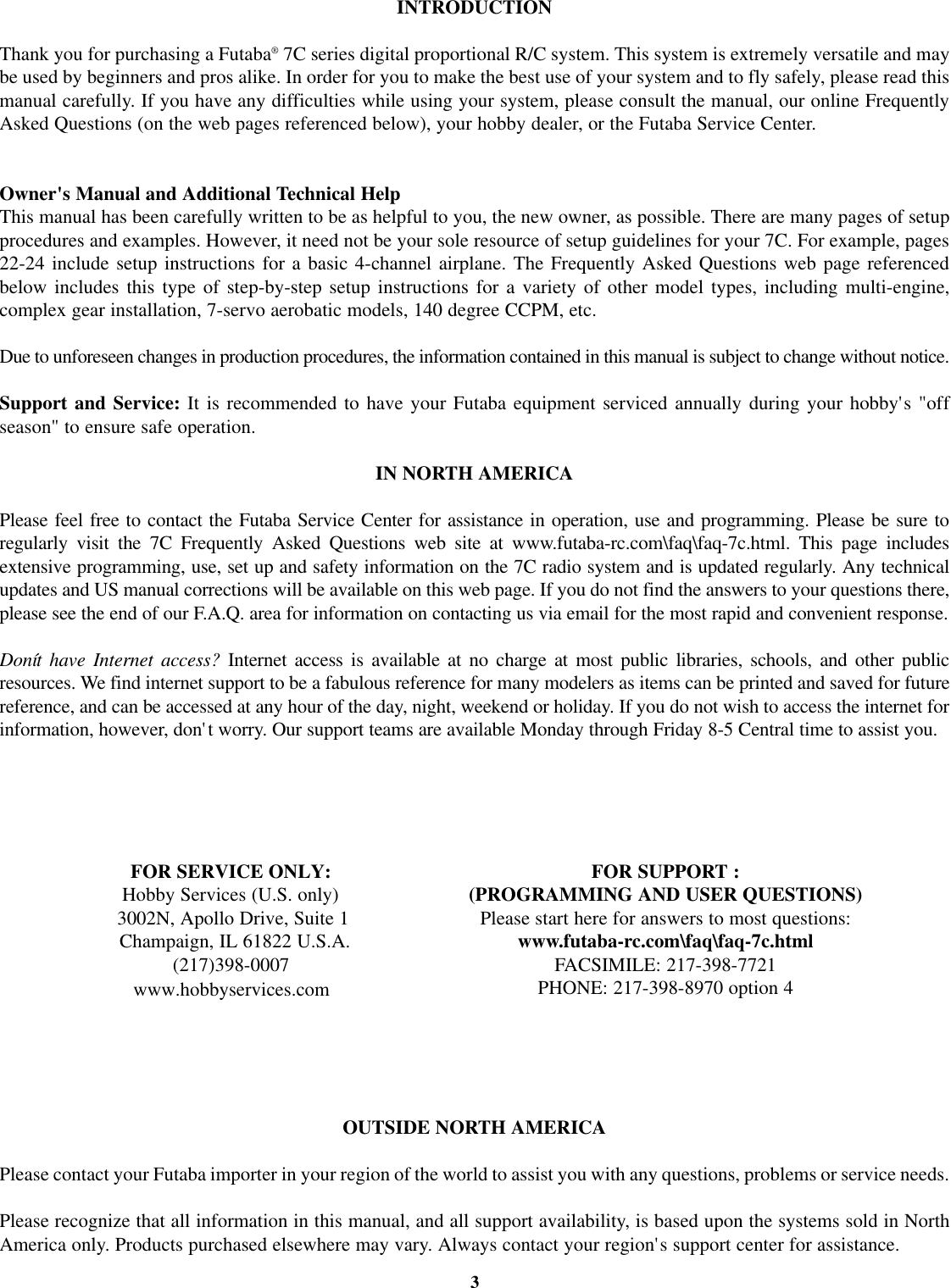
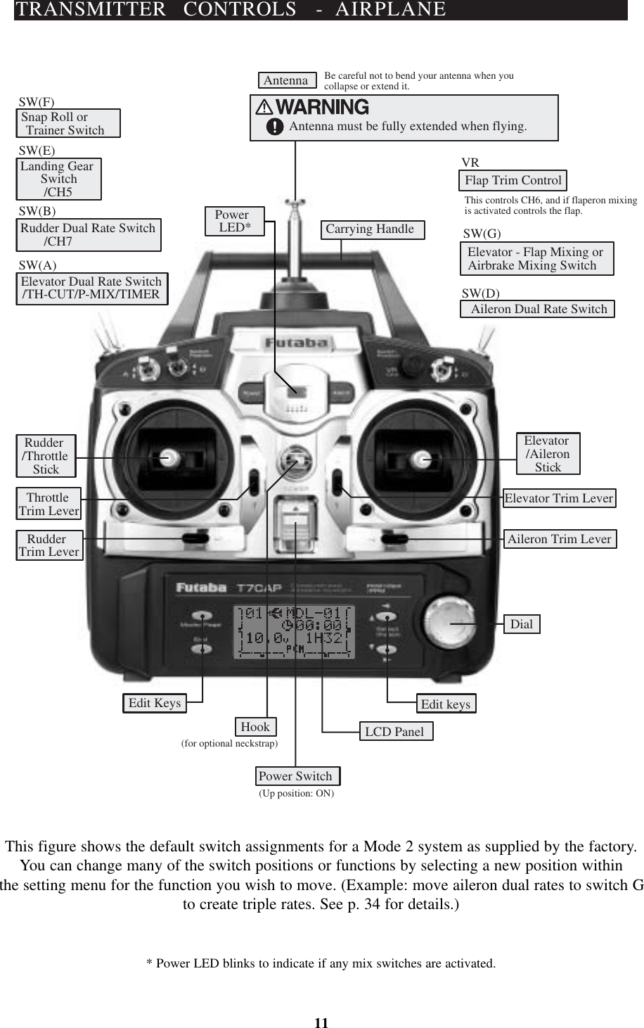
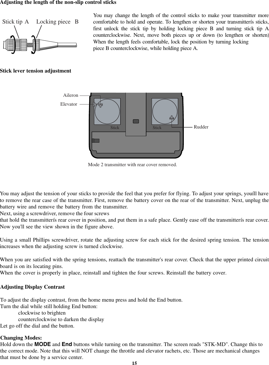
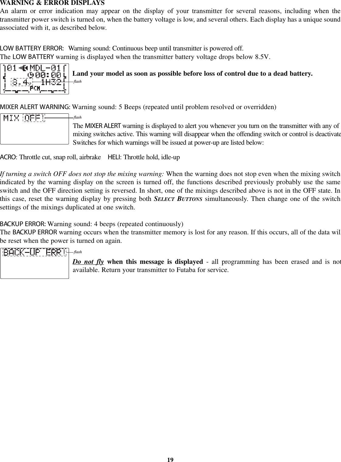
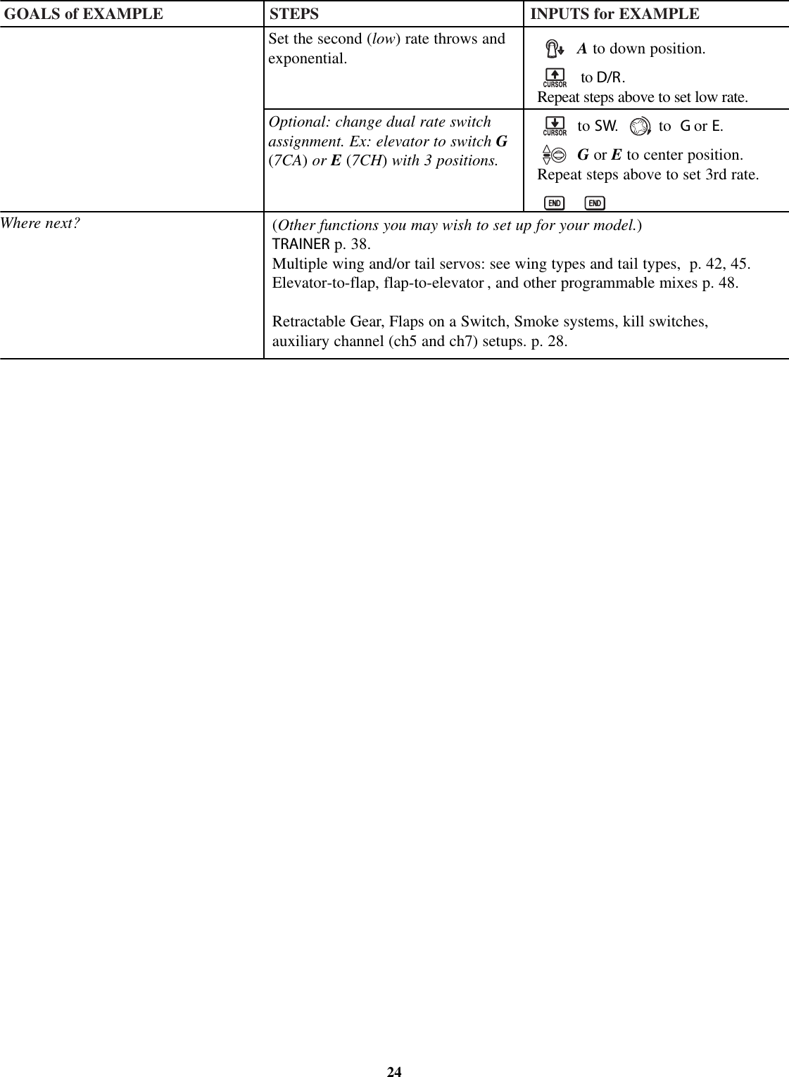
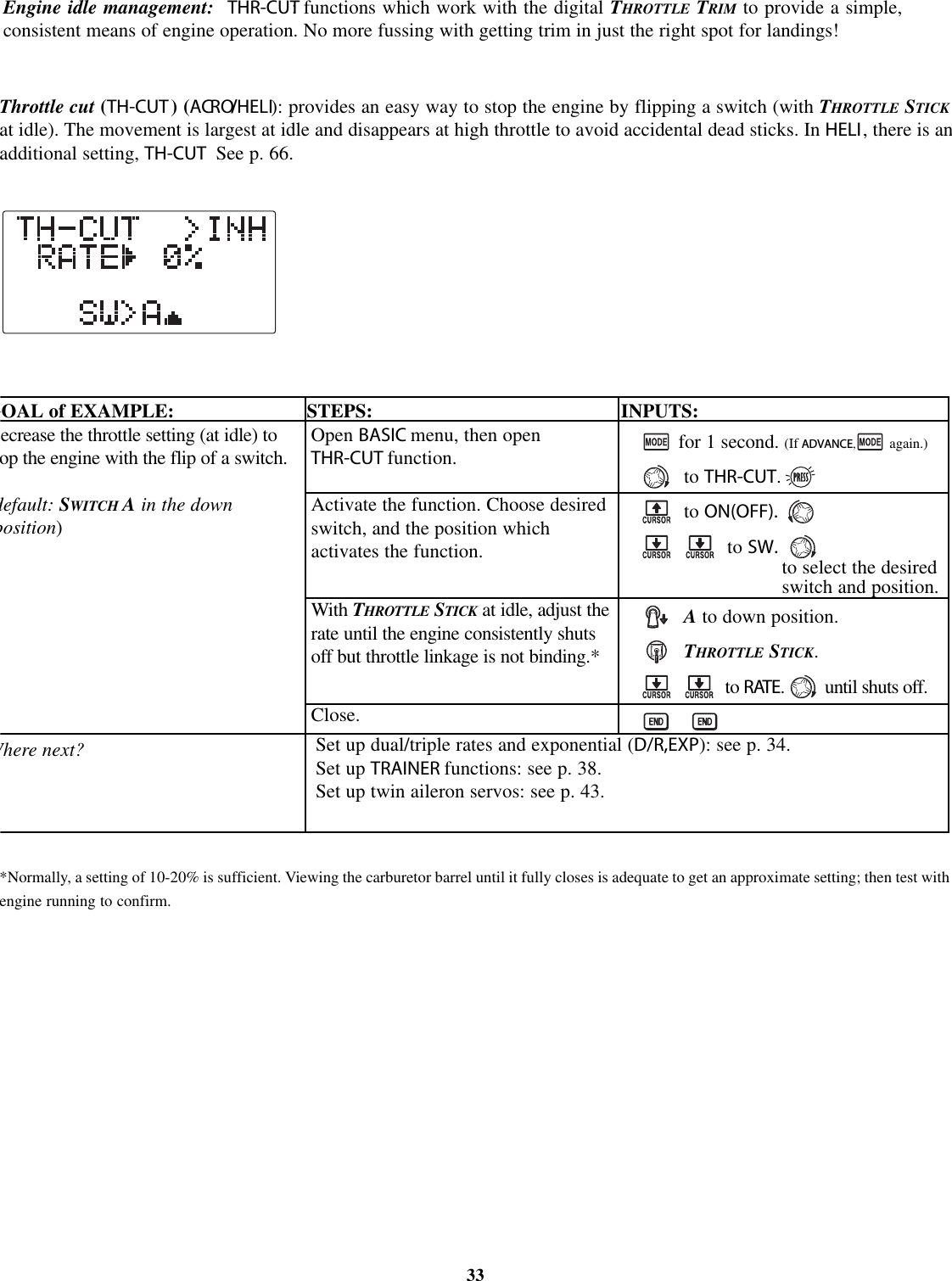
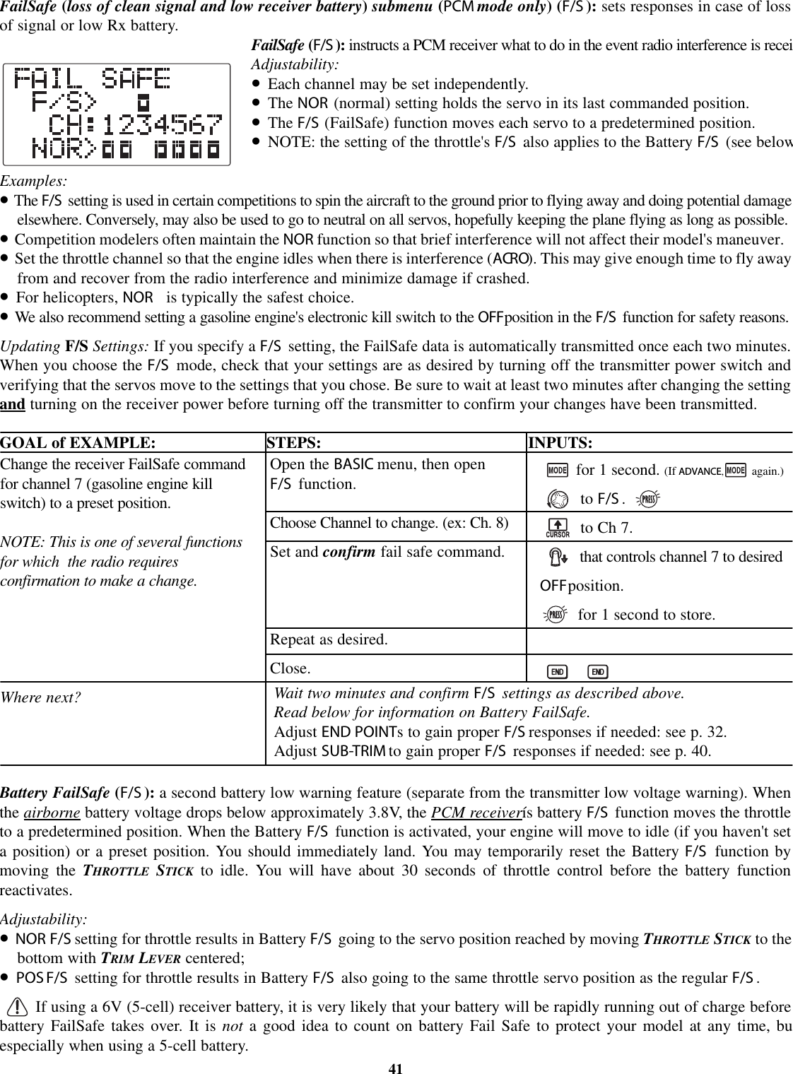
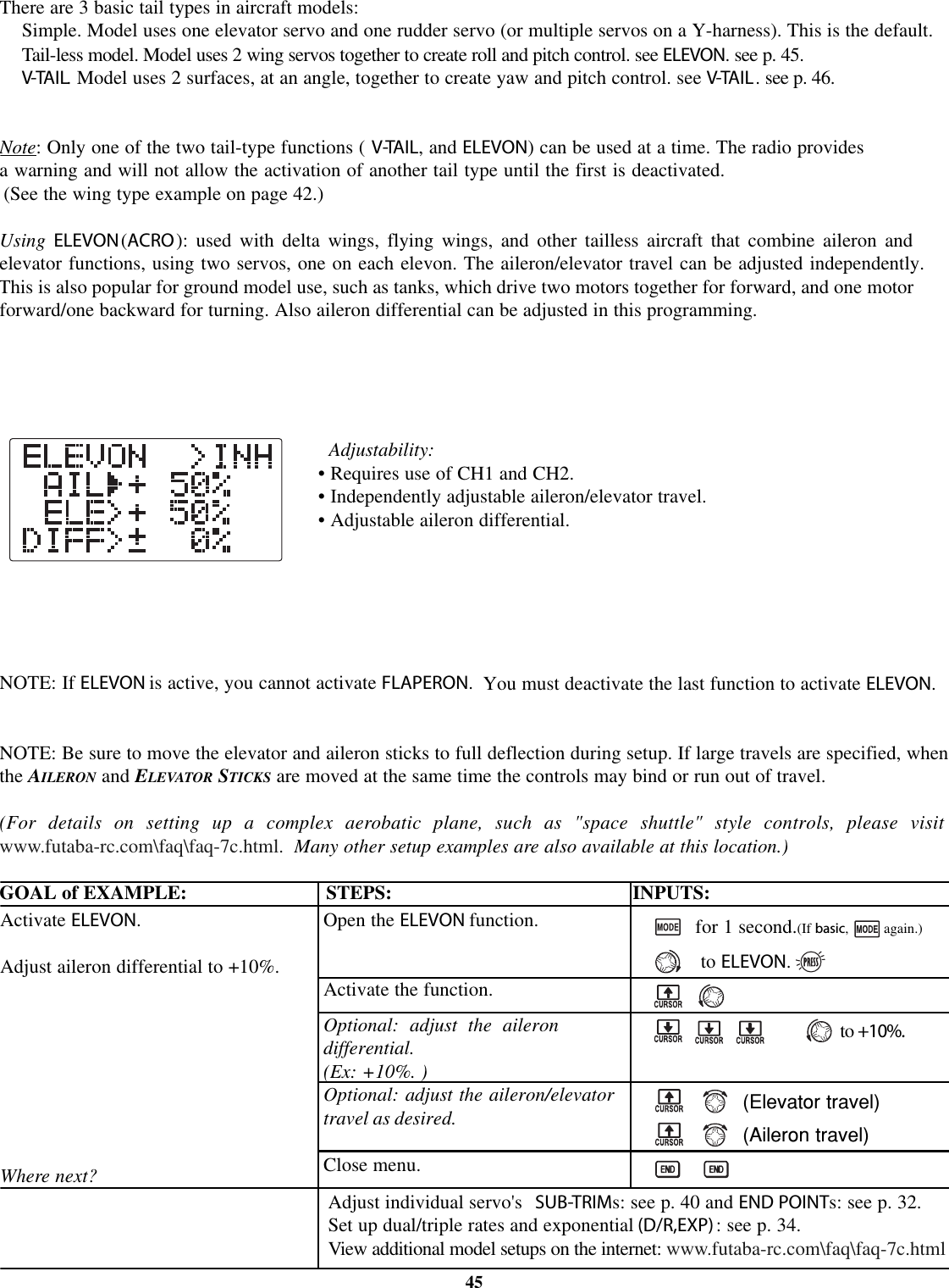
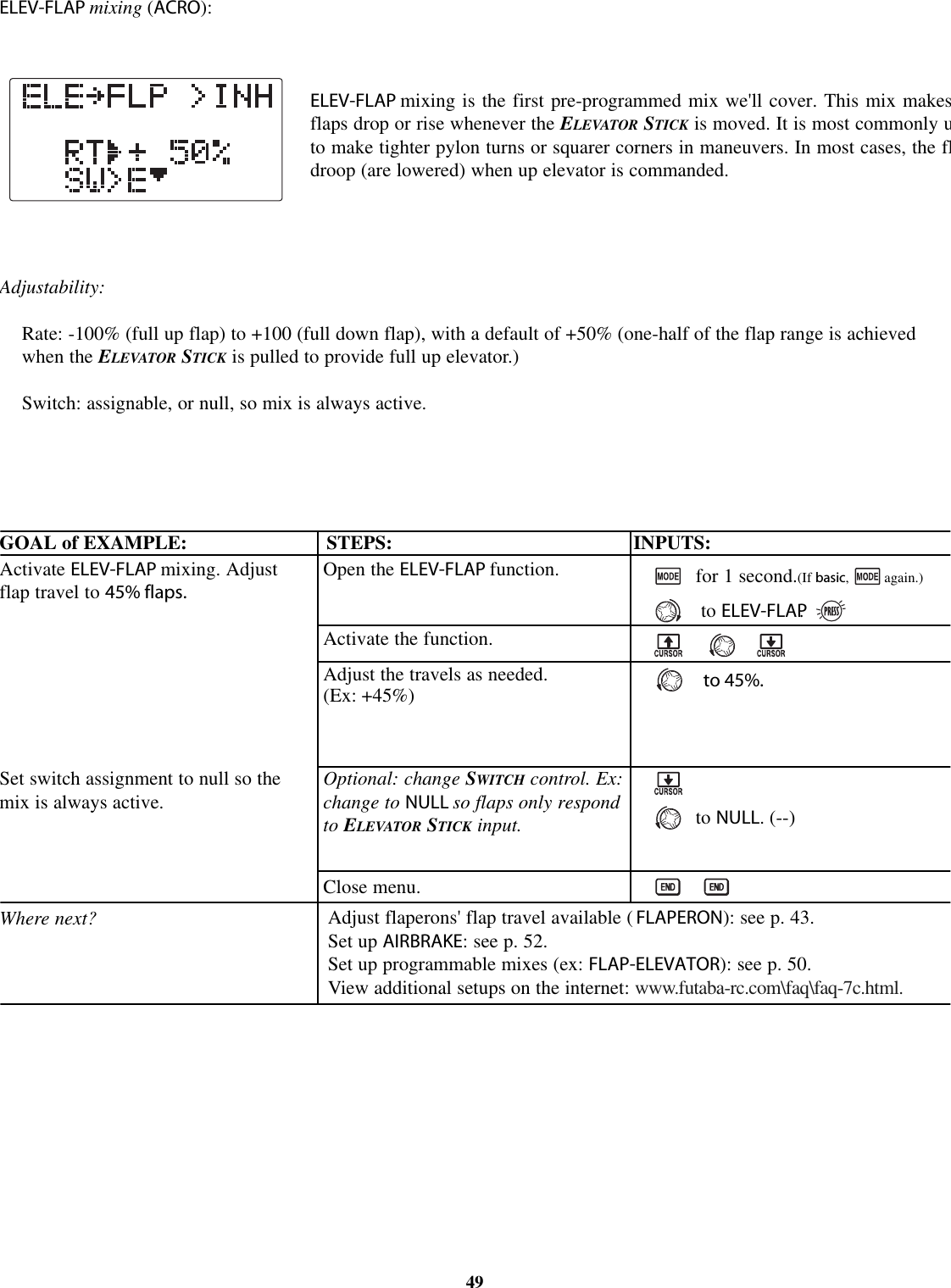
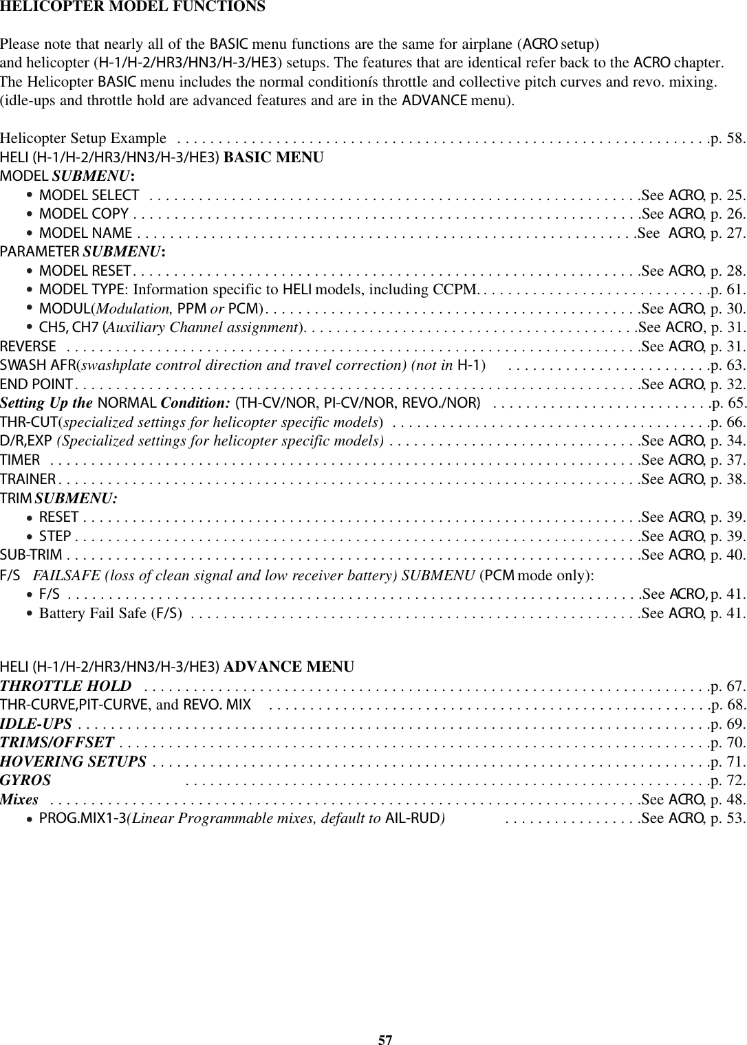
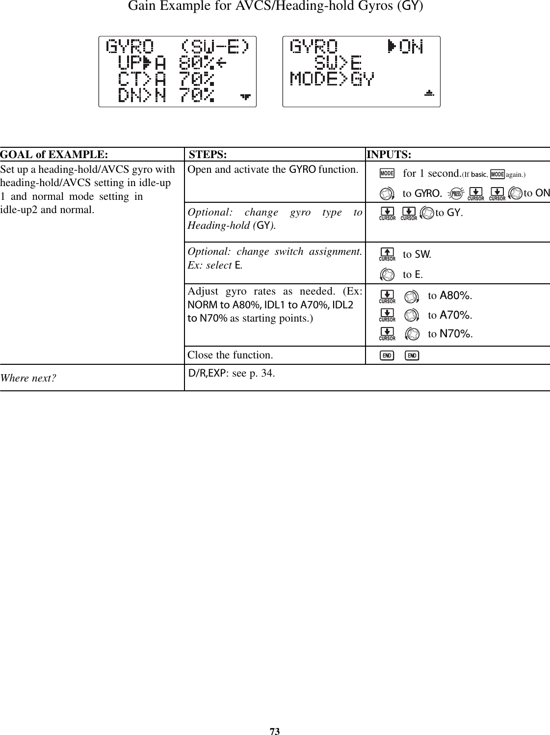
![A QUICK GUIDE: GETTING STARTED WITH A BASIC 4-CHANNEL AIRCRAFTThis guide is intended to help you get acquainted with the radio, to give you a jump start on using your new radio, and to give yousome ideas and direction in how to do even more than you may have already considered. It follows our basic format of allprogramming pages: a big picture overview of what we accomplish; a "by name" description of what we're doing to help acquaintyou with the radio; then a step-by-step instruction to leave out the mystery when setting up your model.For additional details on each function, see that function's section in this manual. The page numbers are indicated in thegoals column as a convenience to you.See p.21 for a legend of symbols used.GOALS of EXAMPLE STEPS INPUTS for EXAMPLEPrepare your aircraft. Install all servos, switches, receivers per your model's instructions.Turn on transmitter then receiver; adjust all linkages so surfaces are nearly centered.Mechanically adjust all linkages as close as possible to proper control throws.Check servo direction.Make notes now of what you will need to change during programming.22Name the model.P. 25.[Note that you do not need to doanything to "save" or store this data.Only critical changes such as a MODELRESET require additional keystrokes toaccept the change.]Reverse servos as needed for propercontrol operation.P. 31.Adjust Travels as needed to matchmodel's recommended throws (usuallylisted as high rates). P. 32.Open the BASIC menu, then open theMODEL submenu.Go to MODEL NAME.Input aircraft's name.Close the MODEL submenu.In the BASIC menu, open (servo)REVERSE.Choose desired servo and reverse itsdirection of travel. (Ex: reversingrudder servo.)From BASIC menu, choose END POINT.Adjust the servo's end points.(Ex: throttle servo)Close the function.Turn on the transmitter.for 1 second. (If ADVANCE,again.)as needed to highlight MODEL.to choose MODEL.to NAME.(First character of model's name is flashed.)to change first character.When proper character is displayed,to move to next character.Repeat as needed.to return to BASIC menu.4steps to REVERSE.to choose REVERSE.to CH4:RUDDso REV is selected.Repeat as needed.2steps to END POINT.to choose END POINT.to THROTTLE.THROTTLE STICK.until carb barrel closes as desired.THROTTLE STICK.until throttle arm just opens carbfully at full THROTTLE STICK.Repeat for each channel as needed.](https://usermanual.wiki/Futaba/T7C-72/User-Guide-388589-Page-22.png)
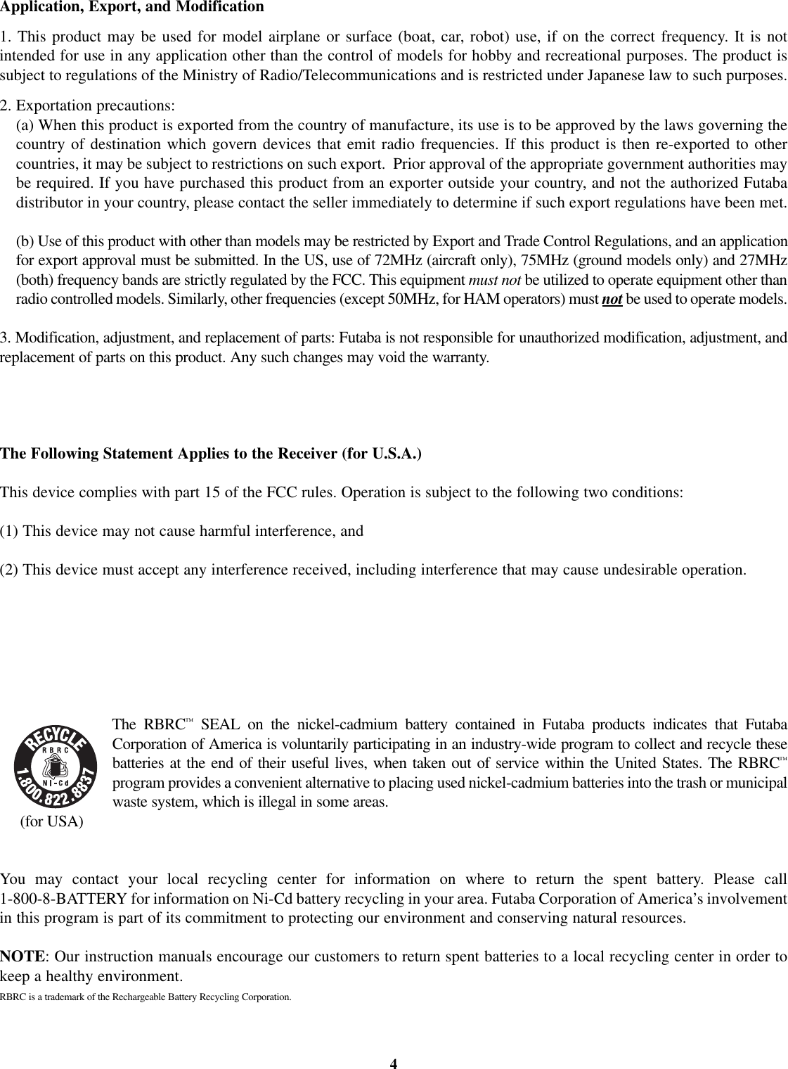
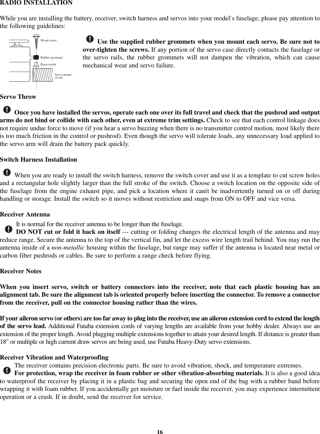
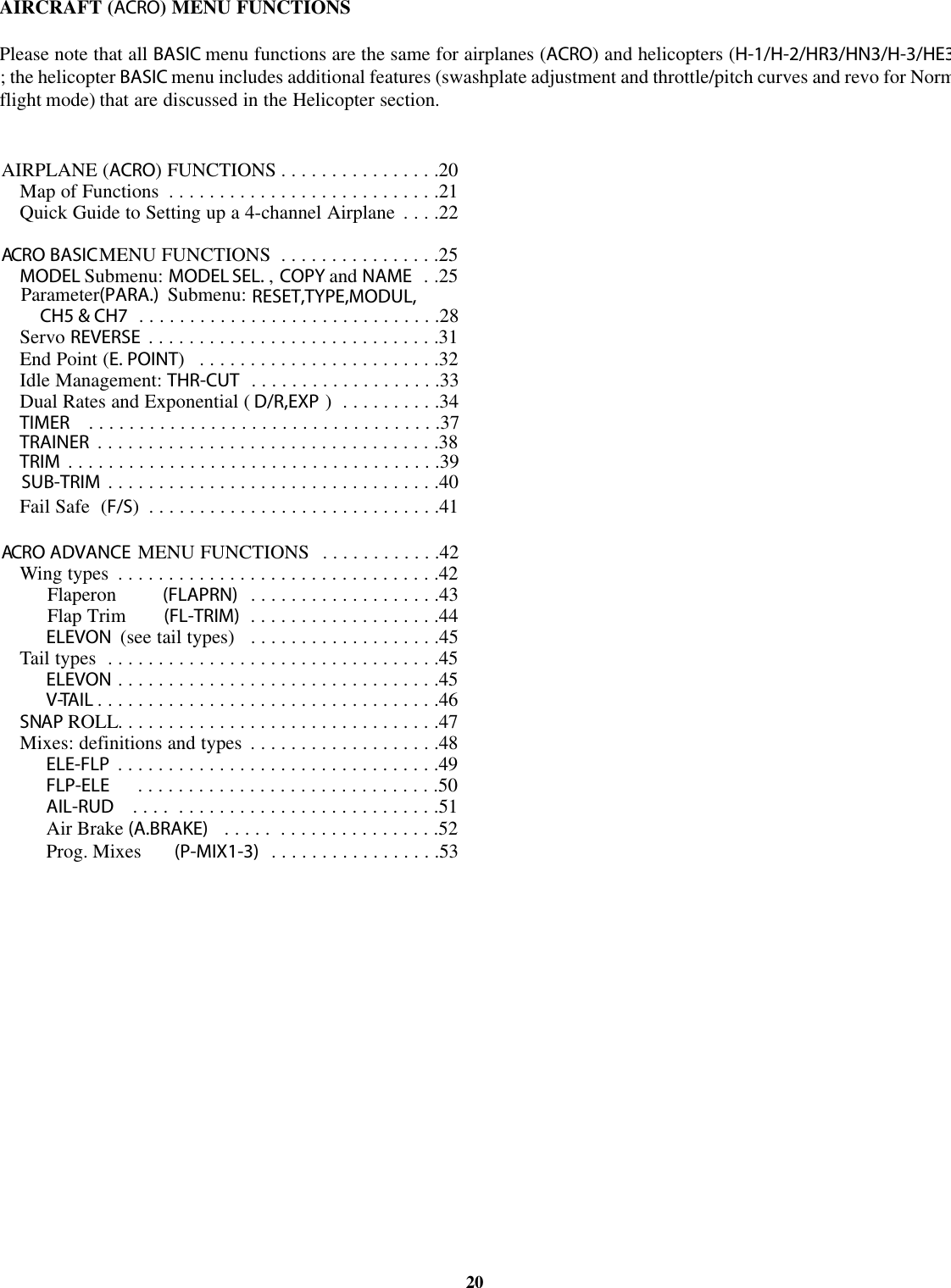
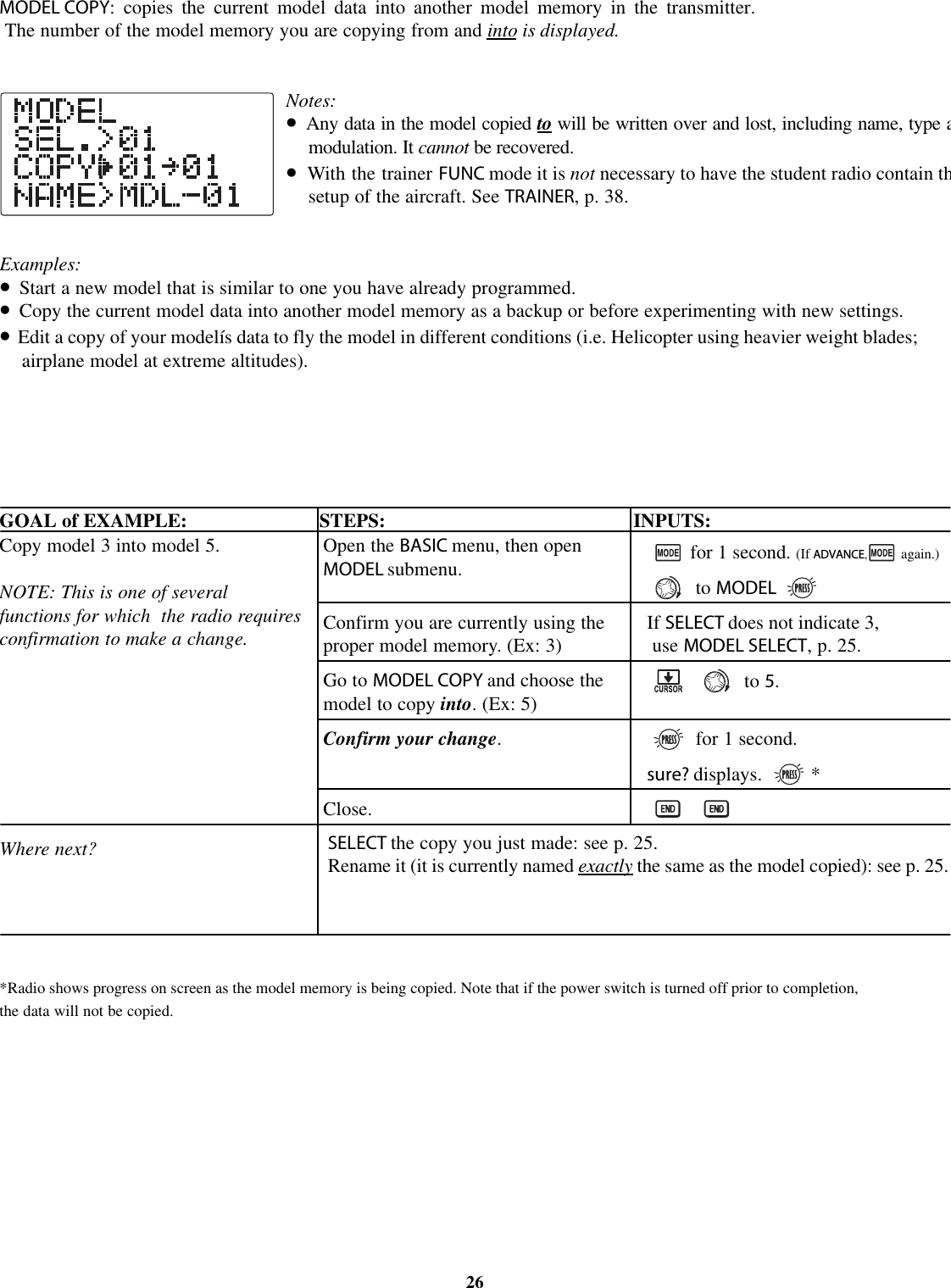
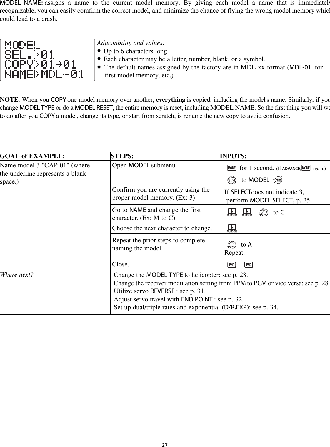
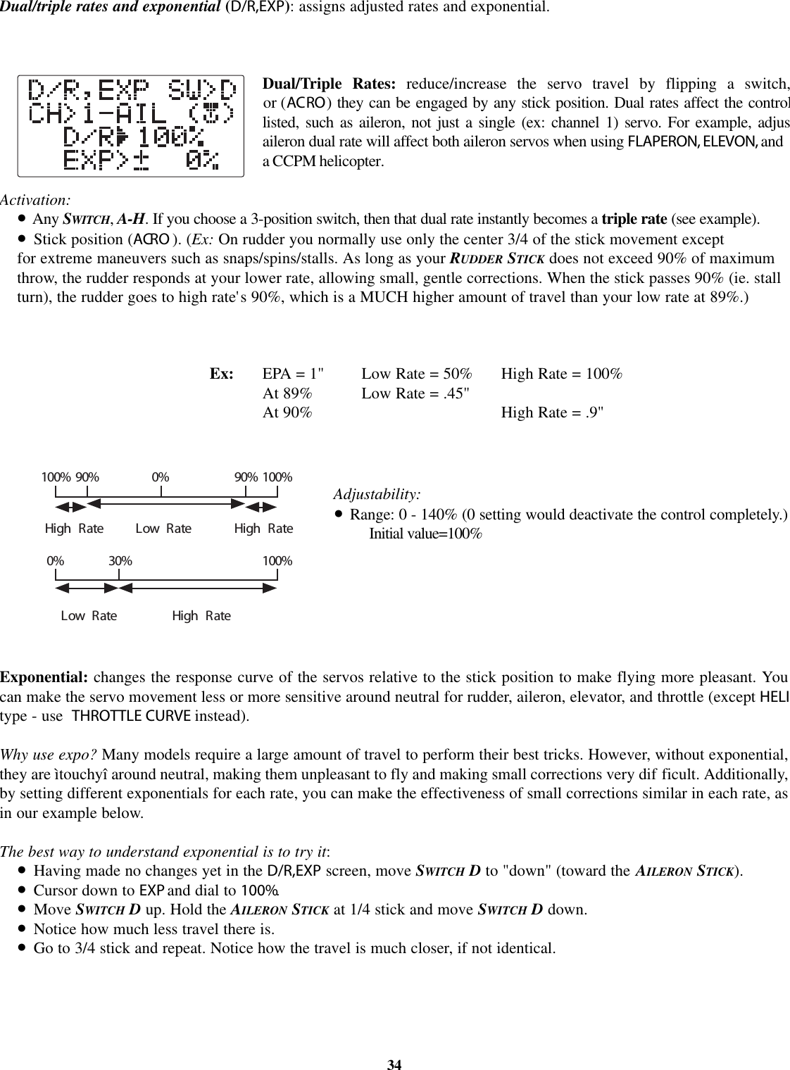
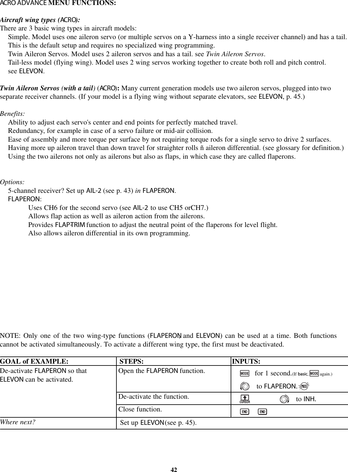
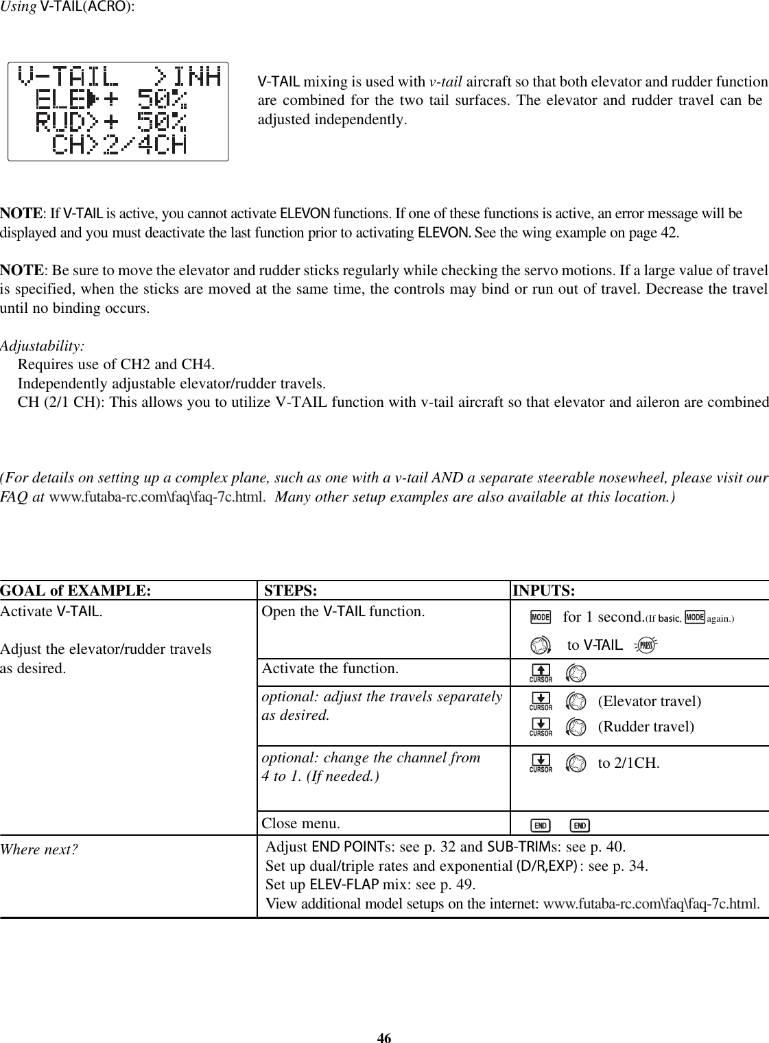
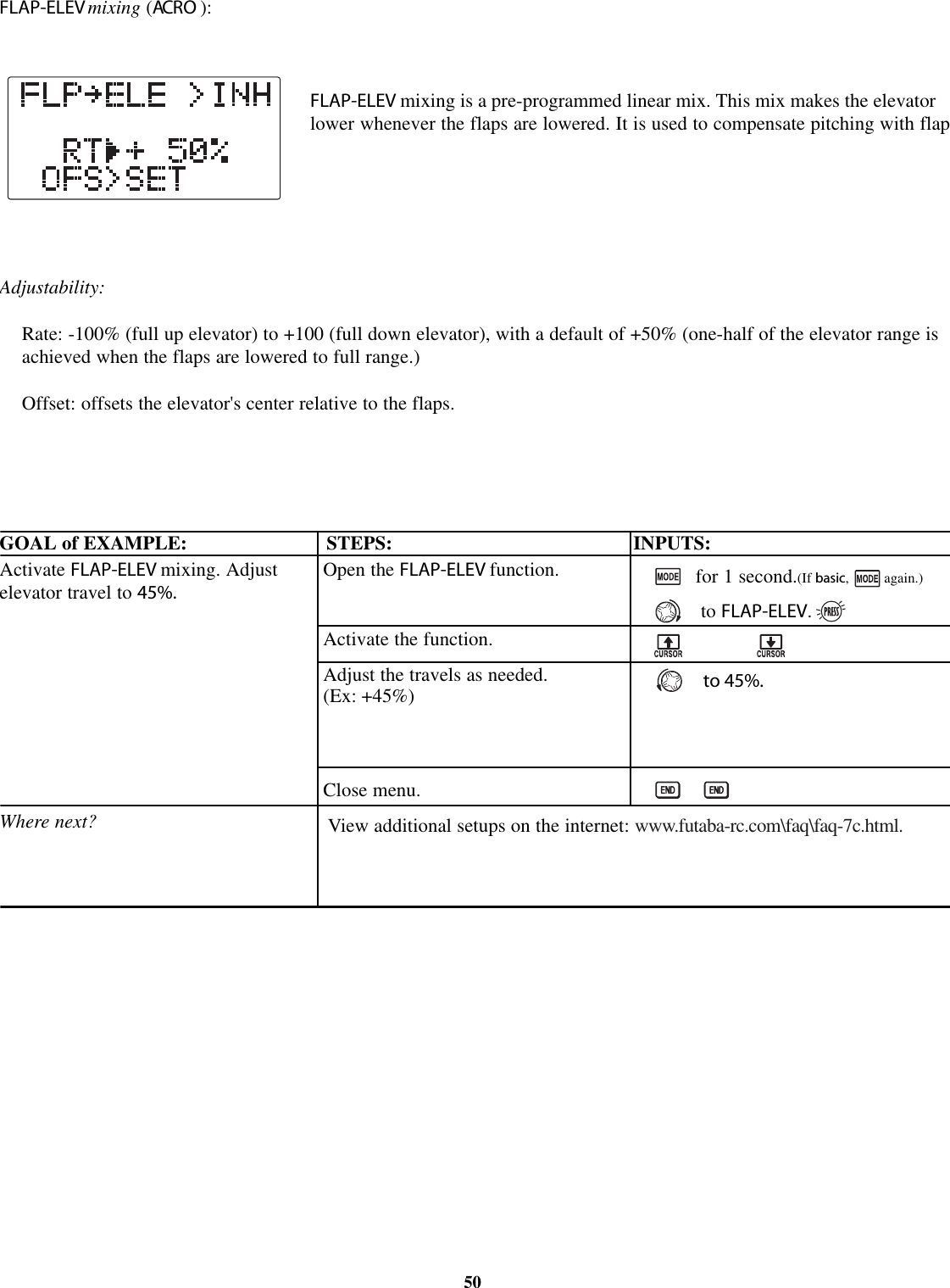
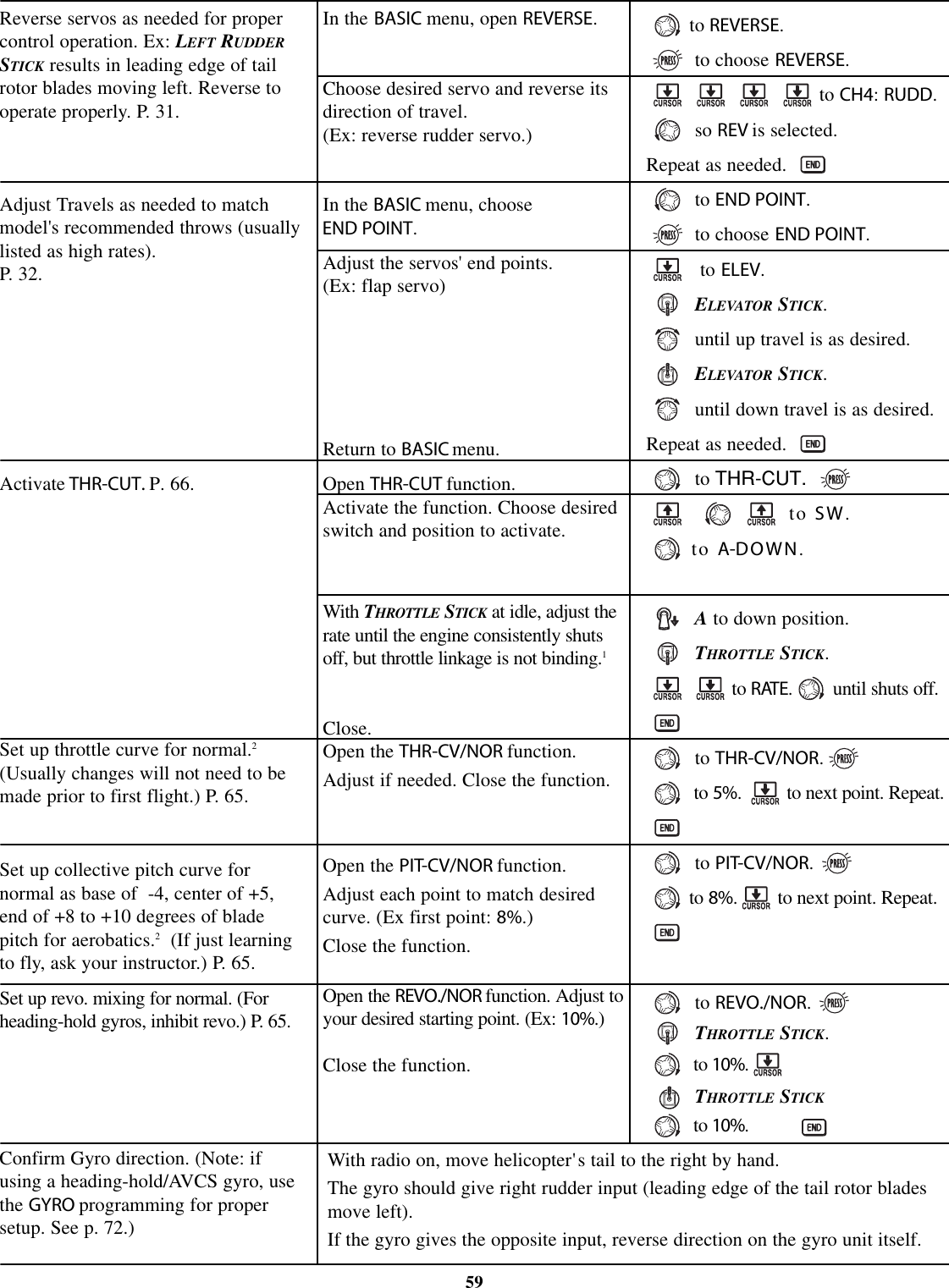
![ALOOK AT THE RADIO'S FUNCTIONS STEP BY STEPMODELsubmenu: includes three functions that manage model memory: MODEL SELECT,MODEL COPY and MODEL NAMSince these functions are all related, and are all basic features used with most models, they are together in the MODELsubmenu of the BASIC menu.MODEL SELECT:This function selects which of the 10 model memories in thetransmitter to set up or fly.(Each model memory may be of a different model type from the other memories.GOAL: STEPS: INPUTS:NOTE: When you choose a new model in theMODEL SELECT function, if the new model is set tothe other modulation, you must cycle the transmitterpower to change modulations. If you do not cyclethe power, the modulation type will flash on thehome screen to remind you. You are stilltransmitting on the other modulation until you affectthis change.25Select Model #3.NOTE: This is one of several functionsfor which the radio requiresconfirmation to make a change.Open BASIC menu, then open MODELsubmenu.Choose Model #3.Confirm your change.Close.for 1 second. (If ADVANCE,again.)if required to MODEL.to 3.for 1 second.sure? displays.Confirm proper modulation of newmodel memory.Where next?If PPM or PCM are flashing in the middle of the lower side, then the new model is sefor the other receiver type. Turn the transmitter off/on to change the modulation.NAME the model: see p. 27.Change MODEL TYPE (aircraft, heli): see p. 28.Change modulation [FM (PPM)orPCM]: see p. 28.Utilize servo REVERSE: see p. 31.Adjust END POINTs: see p. 32.Set up TH-CUT for throttle management: see p. 33.FLASHING](https://usermanual.wiki/Futaba/T7C-72/User-Guide-388589-Page-25.png)
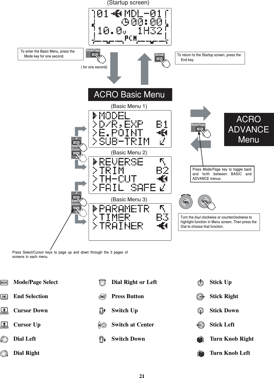
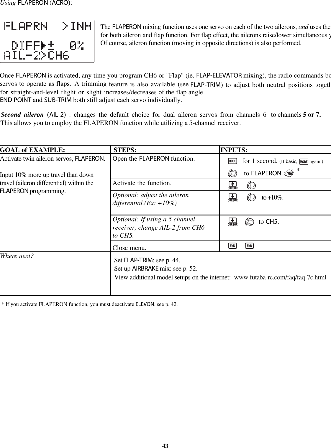
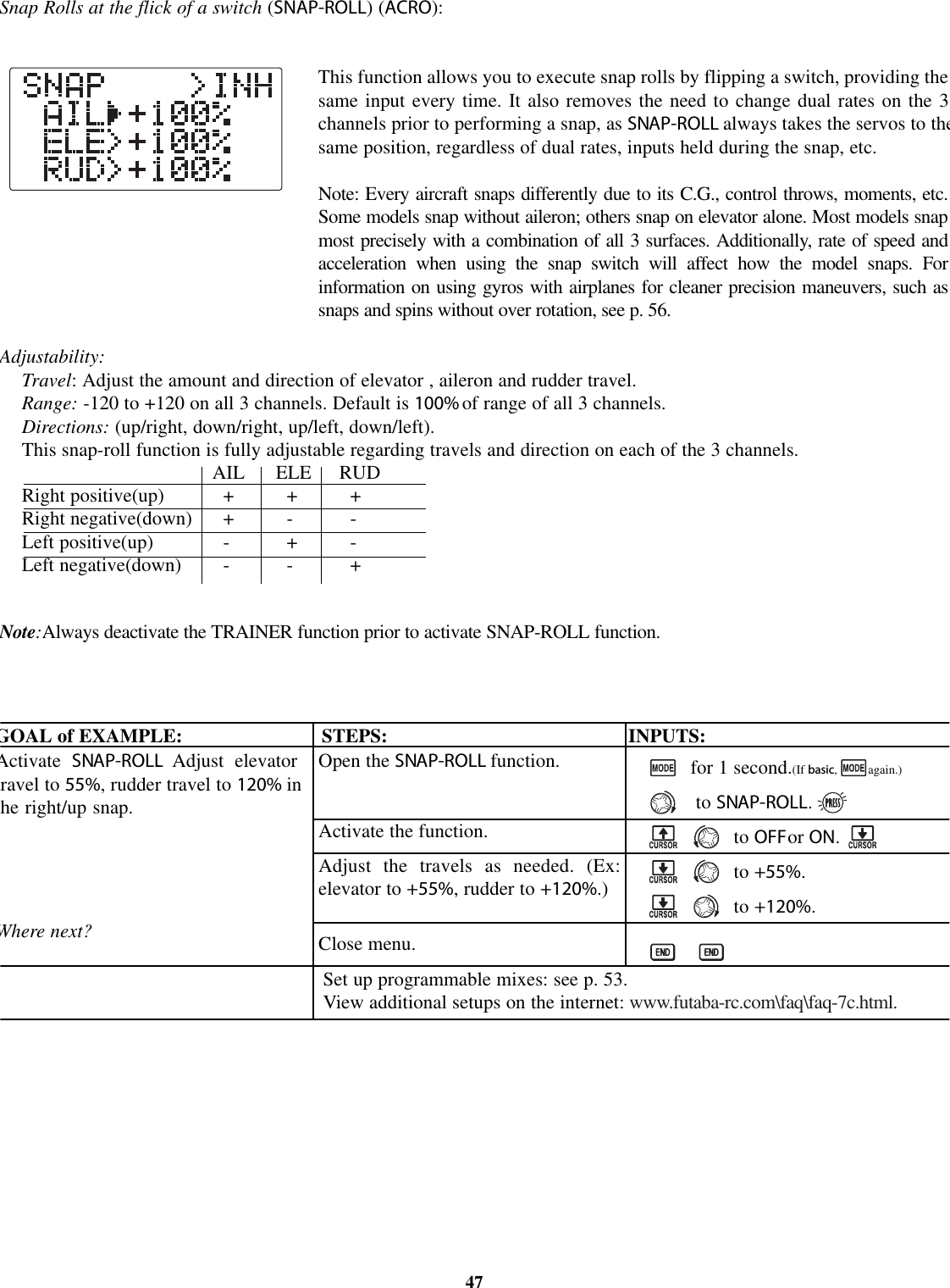
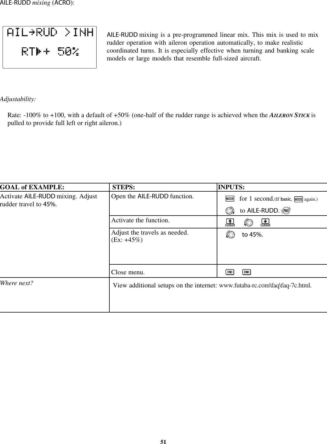
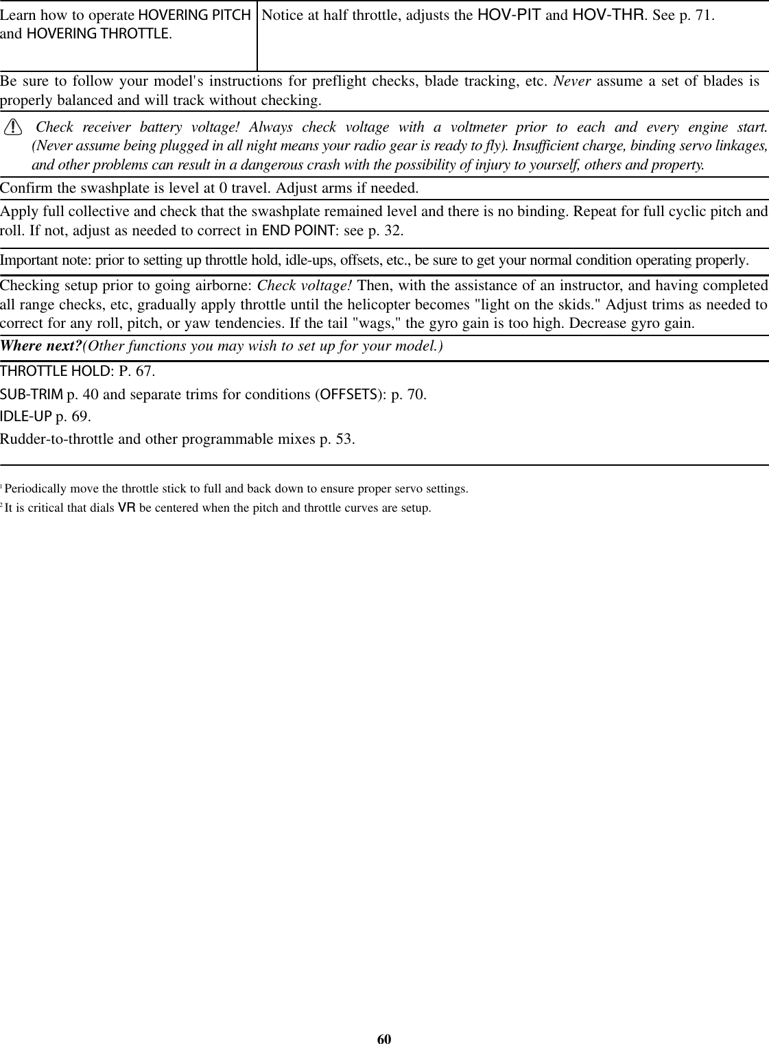
![PARAMETER submenu:sets those parameters you would likely set once, and then not disturb again.Once you have selected the correct model you wish to work with, the next step issetting up the proper parameters for this specific model:•What is the model's type?•What type is the receiverís modulation [PPM(FM) or PCM]?•If you are utilizing either of the twin aileron functions, do you need to tell theyour receiver is only 5 channels?First it is important to clear out any old settings in the memory from prior use, using the MODEL RESET.MODEL RESET:completely resets all data in the individual model you have currently selected. Don't worry - there is no wayyou can accidentally delete all models in your radio with this function. Only a service center can completely reset yourradio's entire memory at once. To delete each model in your radio's memory (for example when selling), you must SELECTeach model, reset that memory, then go SELECT the next memory, etc.Note that when you COPY one model memory into another or change the model's type, you need not delete all existing datafirst by using this function. COPY completely overwrites anything in the existing model memory, including MODEL NAMThe MODEL TYPE function overwrites all data except name and MODUL.GOAL of EXAMPLE: STEPS: INPUTS:*Radio shows progress on screen as the model memory is being reset. Note that if the power switch is turned off prior to completion,the data will not be reset.28Reset model memory 1.NOTE: This is one of severalfunctions for which the radio requiresconfirmation to make a change.Where next?Confirm you are currently using theproper model memory. (Ex: 1)Open PARAMETER submenu.Reset the Memory.Confirm the change.Close.On home screen, check model nameand number on top right. If it is notcorrect, use MODEL SELECT,p.25.for 1 second. (If ADVANCE,again.)to 3rd page of menu.to PARAMETER.for one second.sure? displays. *Now that the memory is reset, name has returned to the default (Ex: MDL-01).NAME the model: p. 25.COPY adifferent model into this memory: p. 25.SELECT a different model to edit or delete: p. 25.Change the MODEL TYPE to helicopter: see p. 28.Change the receiver modulation from FM(PPM)toPCM or vice versa: see p. 28.Utilize servo REVERSE:seep. 31.Adjust servo travel with END POINT:seep. 32.Set up dual/triple rates and exponential (D/R,EXP): see p. 34.](https://usermanual.wiki/Futaba/T7C-72/User-Guide-388589-Page-28.png)
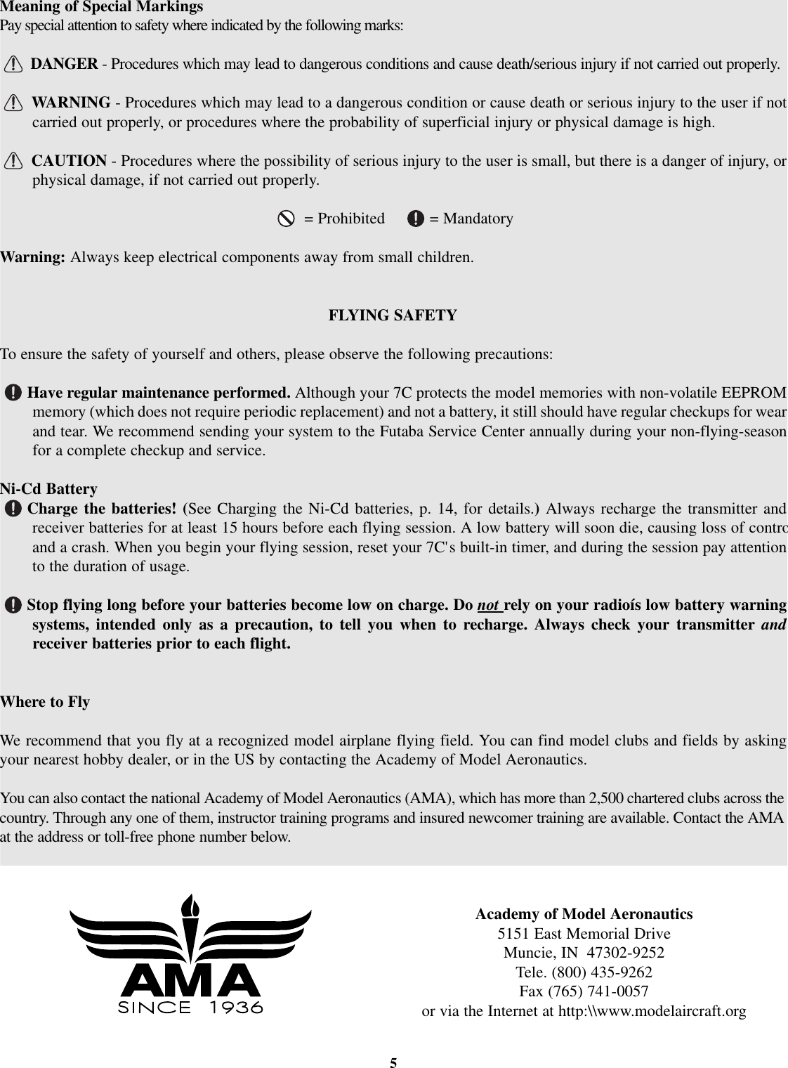
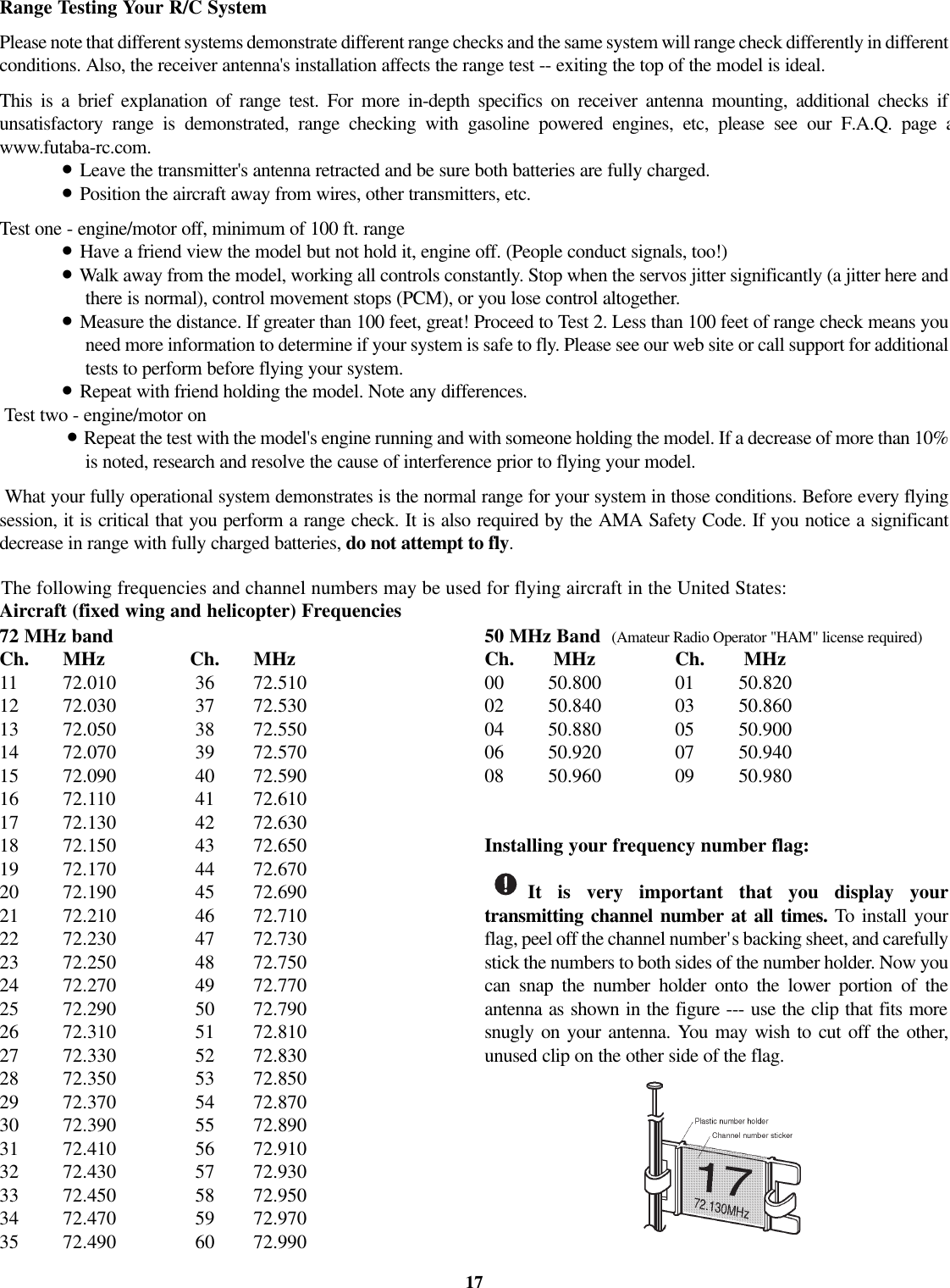
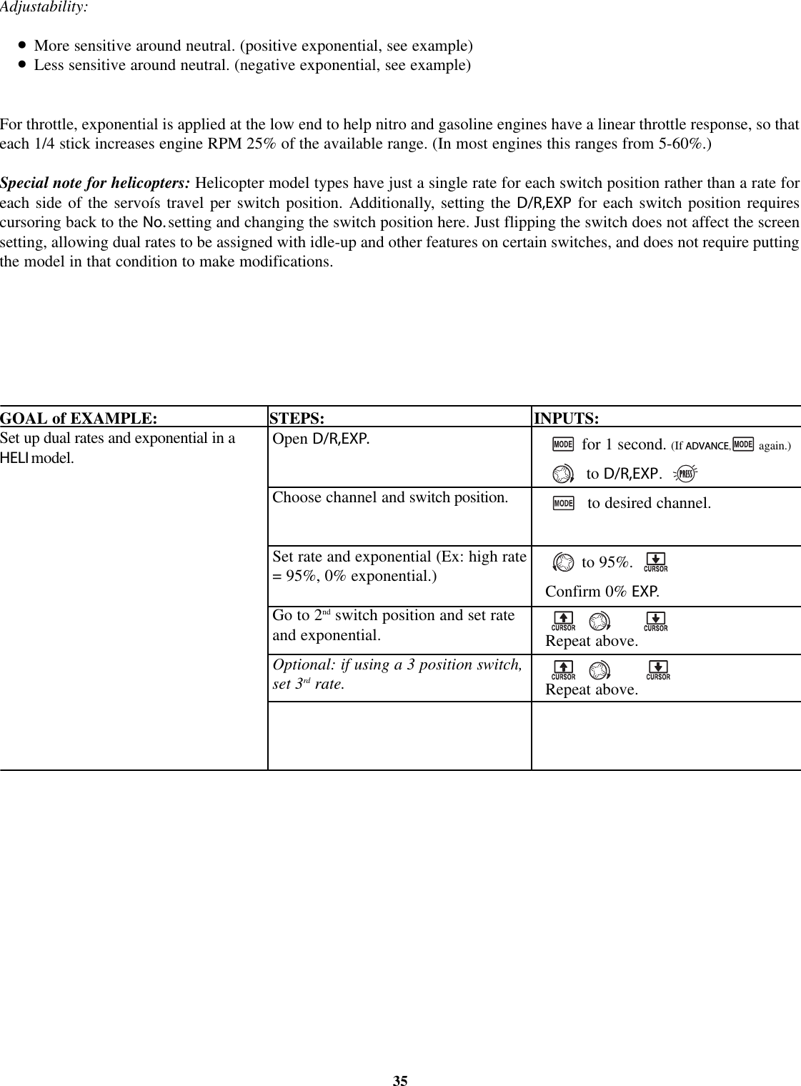
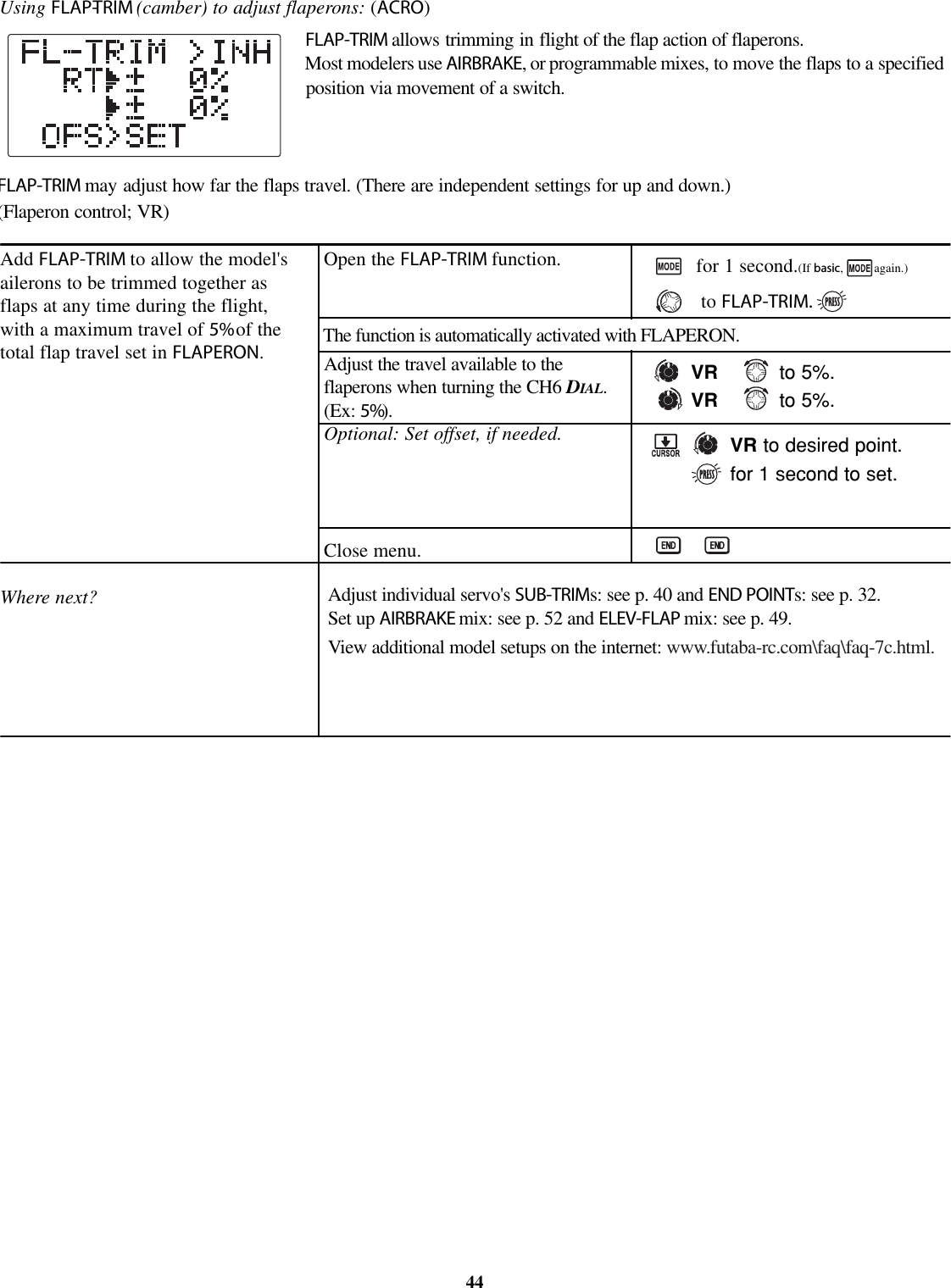
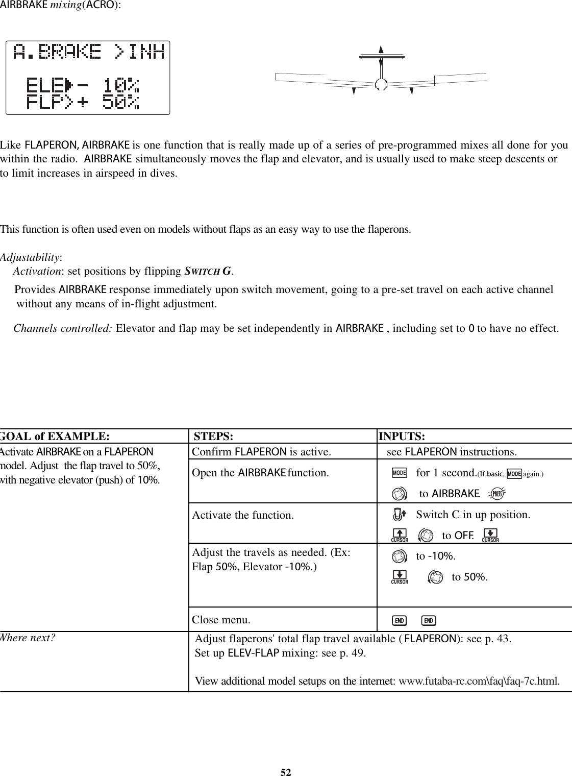
![MODEL TYPE:sets the type of programming used for this model.The 7C has 10 model memories, which can each support:•one powered aircraft (ACR O)memory type (with multiple wing and tailconfigurations. See FRAPERON, ELEVON and V-TAIL for further information.);•six helicopter swashplate types, including CCPM. See Helicopter MODEL TYPEfor details, p. 61.Before doing anything else to set up your aircraft, first you must decide which MODEL TYPE best fits this particular aircraft(Each model memory may be set to a different model type.) If your transmitter is a 7CA, the default is ACRO.Ifitisa7CH,the default is H-1.Ifyou are using a heliMODEL TYPE, please go to that chapter now to select the proper model type and supportyour model setup. Note that changingMODEL TYPEresets all data for the model memory, including its name.GOAL of EXAMPLE: STEPS: INPUTS:29Select the proper MODEL TYPE for yourmodel. Ex: ACRO.[NOTE: This is one of several functionsthat requires confirmation to make achange. Only critical changes requireadditional keystrokes to acceptthe change.]Open the BASIC menu, then open thePARAMETER submenu.Go to MODEL TYPE.Select proper MODEL TYPE.Ex: ACRO.Confirm the change. Close PARAMETER.Turn on the transmitter.for 1 second. (If ADVANCE,again.)then to highlight PARAMETERto choose PARAMETER.to TYPE.to ACRO.for1second.sure? displays. to confirm.to return to BASIC menu.](https://usermanual.wiki/Futaba/T7C-72/User-Guide-388589-Page-29.png)
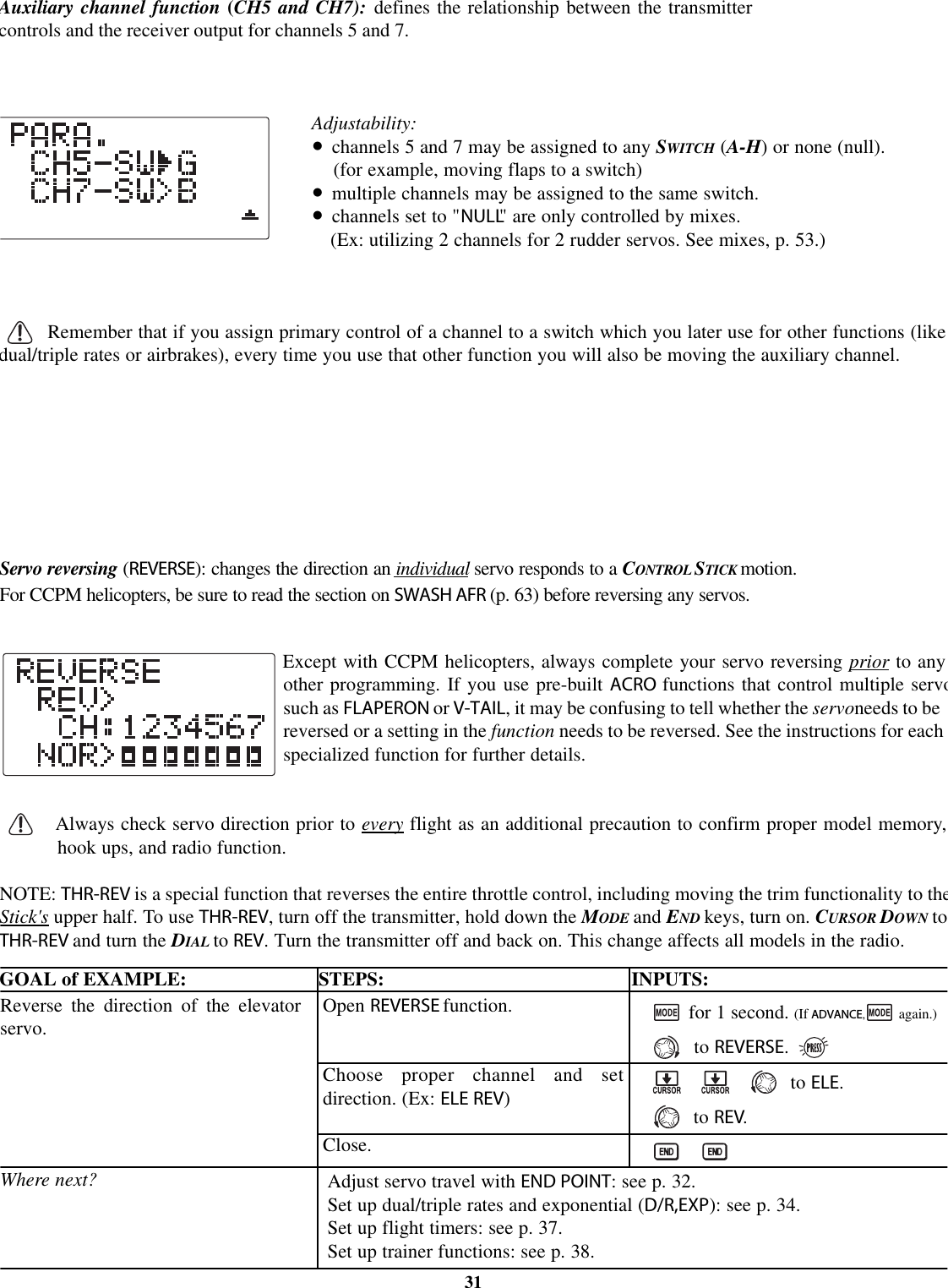
![Modulation select (MODUL): sets the type of modulation transmitted.The modulation of your receiver will determine whether you utilize PPM or PCM setting in MODUL during transmissionNote that you have to turn your transmitter off and back on before a modulation change becomes effective. If you choosePCM,besure you understand and set the FailSafe (F/S) settings as you intended (see p. 41).PCM =Pulse Code Modulation PPM =Pulse Position Modulation (also called FM).Adjustability:•PCM setting for all Futaba PCM1024 receivers, regardless of number of channels(ie.R138DP/148DP/149DP, R309DPS);•PPM setting for all Futaba compatible (negative shift) FM receivers, regardless ofnumber of channels (ie. R127DF, R123F, R148DF).•Not compatible with PCM512 receivers such as the R128DP and R105iP.•Not compatible with other brands of PCM receiver, or positive shift FM receivers(ie. JR, Airtronics).GOAL of EXAMPLE: STEPS: INPUTS:NOTE: When you change models in MODEL SELECT,ifthenew model is set to the other modulation type, you mustcycle the transmitter power to change modulations. Themodulation will flash on the home screen to remind youuntil you do so. See p. 25, MODEL SELECT, for details.30Change model 1 from FM (PPM)toPCMWhere next?Confirm you are currently using theproper model memory (Ex: 1)Open BASIC menu, then openPARAMETER submenu.Go to MODUL and change setting.Close menu and cycle power.On home screen, check model name andnumber on top and the modulationon bottom. If it is not the correctmodel, use MODEL SELECT,p.25.for 1 second. (If ADVANCE,again.)to 3rd page of menu.to PARAMETER.to MODUL.toPCM.PCM flashes on screenPOWER OFF.POWER ON.Now that the model is in the proper modulation, the 7C should communicatewith the receiver. If it does not, confirm the modulation/frequency of thereceiver. [Futaba receivers ending in F use PPM (ex: R127DF), ending in P usePCM (ex: R149DP)].Change MODEL TYPE to helicopter: see p. 28.Set F/S settings for when PCM receiver sees interference: see p. 41.Utilize servo REVERSE:seep. 31.Adjust servo travel with END POINT:seep. 32.Set up dual/triple rates and exponential (D/R,EXP): see p. 34.](https://usermanual.wiki/Futaba/T7C-72/User-Guide-388589-Page-30.png)
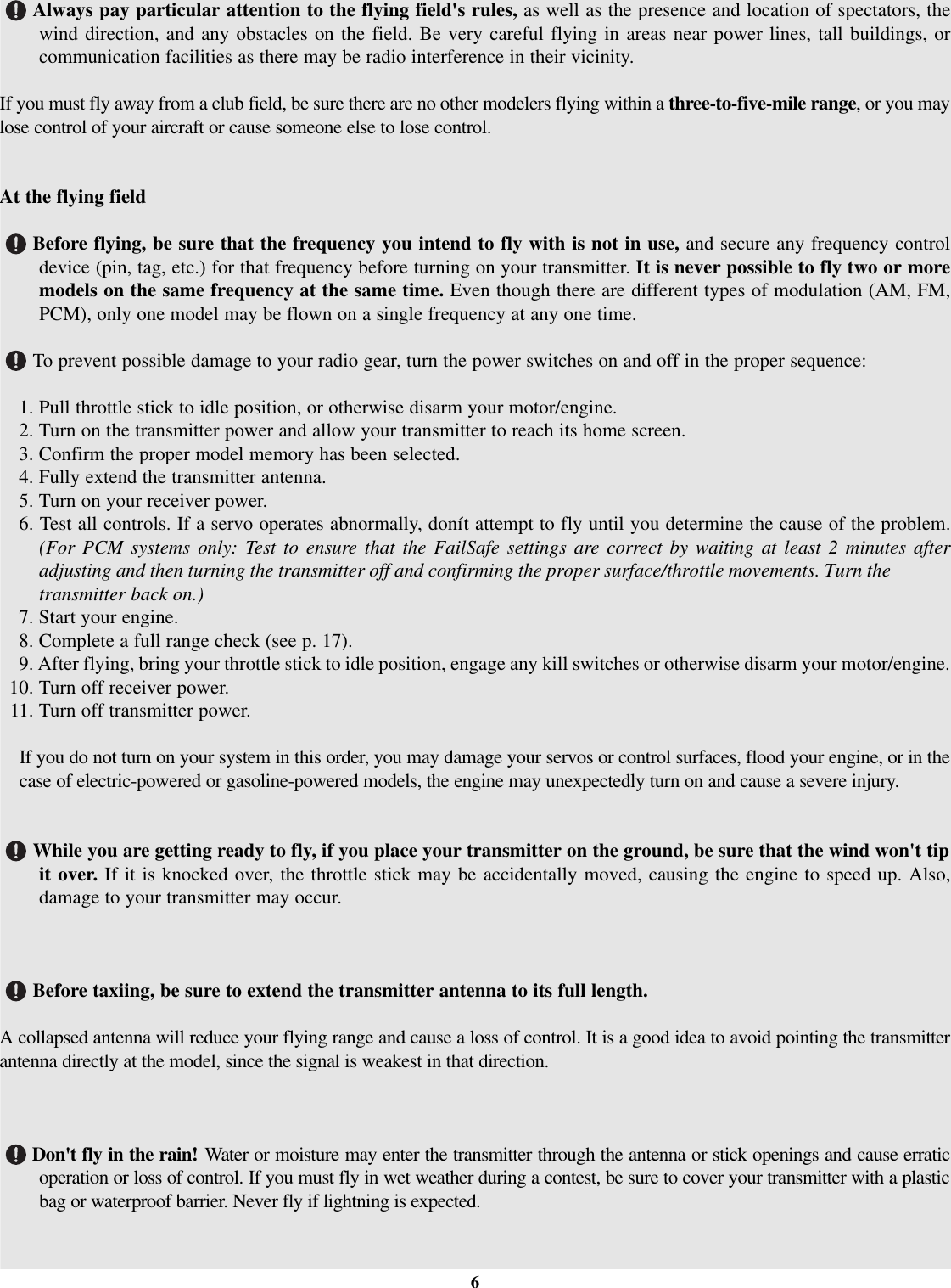
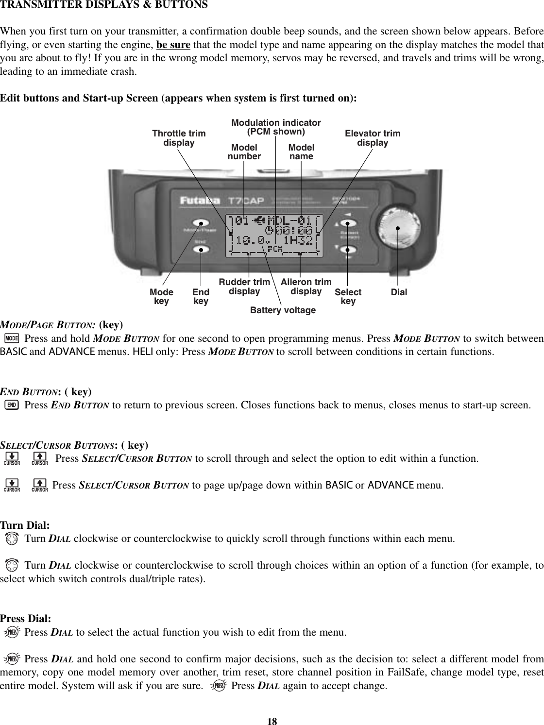
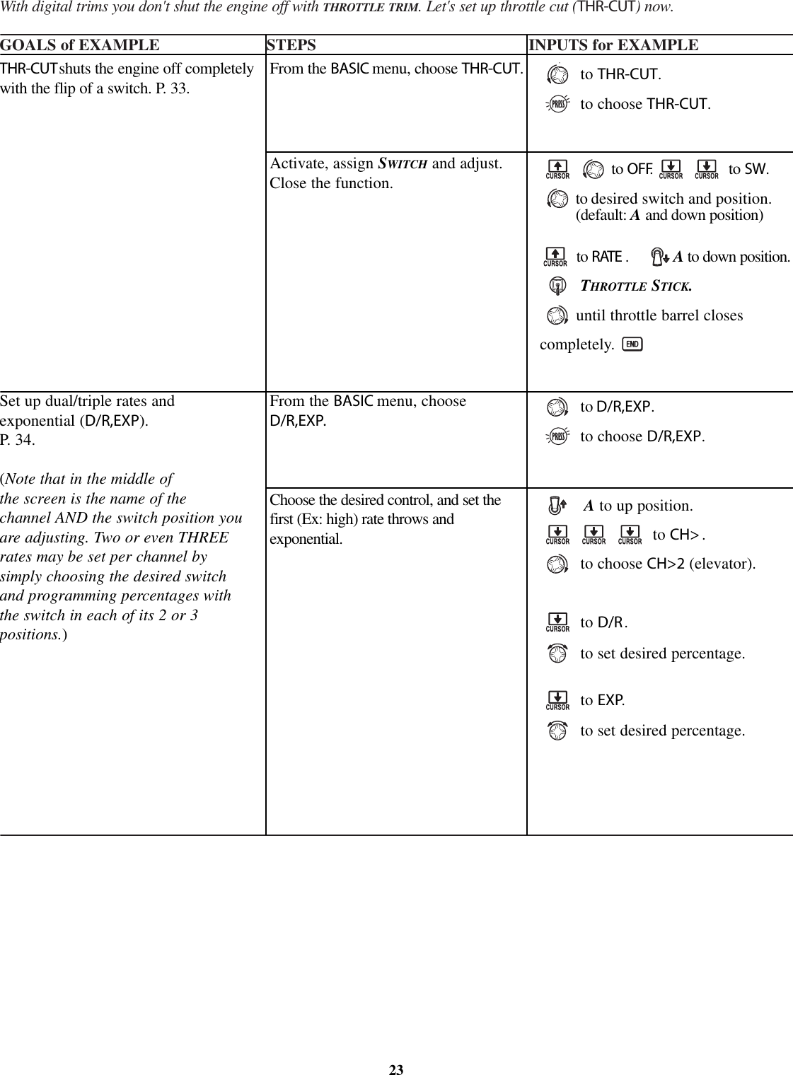
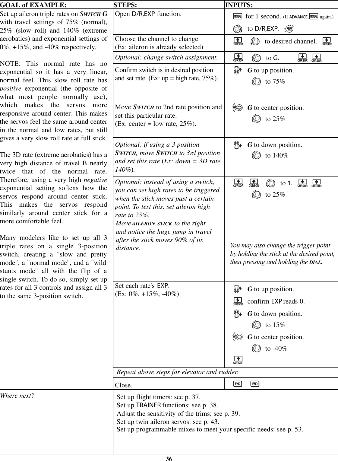
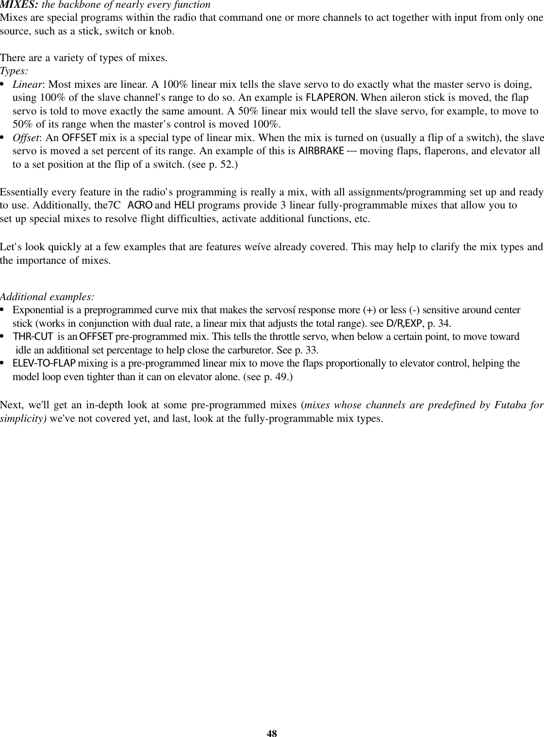
![End Point of servo travel adjustment (E.POINT , also called EPA): the most flexible version of travel adjustmentavailable. It independently adjusts each end of each individual servoís travel, rather than one setting for the servo thataffects both directions. Again, for CCPM helicopters, be sure to see SWASH AFR (see p. 63) prior to adjusting end points.Adjustability:•Can set each direction independently.•Ranges from 0% (no servo movement at all) to 140%. At a 100% setting, the throw othe servo is approximately 40º for channels 1-4 and approximately 55º for channels 5•Reducing the percentage settings reduces the total servo throw in that direction.Examples:•Adjust the throttle high end to avoid binding at the carburetor, and low end to allow for proper carburetor closure.•Adjust flap so up travel is only sufficient for straight and level flight trimming, with full down travel.•END POINT may be adjusted to 0to keep a servo from moving one direction, such as flaps not intended to also operateas spoilers.•Retract servos are not proportional. Changing END POINT will not adjust the servo.END POINT adjusts only the individual servo. It will have noeffect on any other servo that is operated in conjunction withthis servo via mix or preset programming such as FLAPERON ,etc. This is so that each individual servo can becarefully fine-tuned to avoid binding and other conflicts. To adjust the total travel of a function such as FLAPERON,makethe adjustments in that function's controls. For CCPM helicopters, adjust the total travel of the function, such as collectivepitch, in SWASH AFR.Adjust the linkage or the END POINT?It is nearly always best to adjust your linkages to get as close as possible prior toutilizing END POINT. The higher the END POINT setting, the better position accuracy and the more servo power availablenearly any position (except if using digital servos). Higher END POINT values also mean longer travel time to reach thdesired position, as you are utilizing more of the servo's total travel. (For example, using 50% END POINT would give youonly half the steps of servo travel, meaning every click of trim has twice the effect and the servo gets there in half the time).•end point (and moving the linkage) = torque, accuracy, but transit time to get there.•end point (instead of adjusting linkages) = travel time, but torque, accuracy.GOAL of EXAMPLE: STEPS: INPUTS:*You can reset to the initial values by pressing the DIAL for one second.32Decrease the flap servo throw in theupward direction to 5% to allowtrimming of level flight only and downtravel to 85% to prevent binding.Where next?Open END POINT function.Choose proper channel and setdirection. (Ex: flap up 5%)Close.for 1 second. (If ADVANCE,again.)to END POINT.to flap.flap control [default is VR].to 5%.*VR(A).to85%.Move auxiliary channels 5 or 7 to different switch(es): see p. 28.Set up THR-CUT to cut the engine: see p. 33.Set up dual/triple rates and exponential (D/R,EXP): see p. 34.Set up flight timers: see p. 37.Set up trainer functions: see p. 38.Set up twin aileron servos: see p. 43.](https://usermanual.wiki/Futaba/T7C-72/User-Guide-388589-Page-32.png)
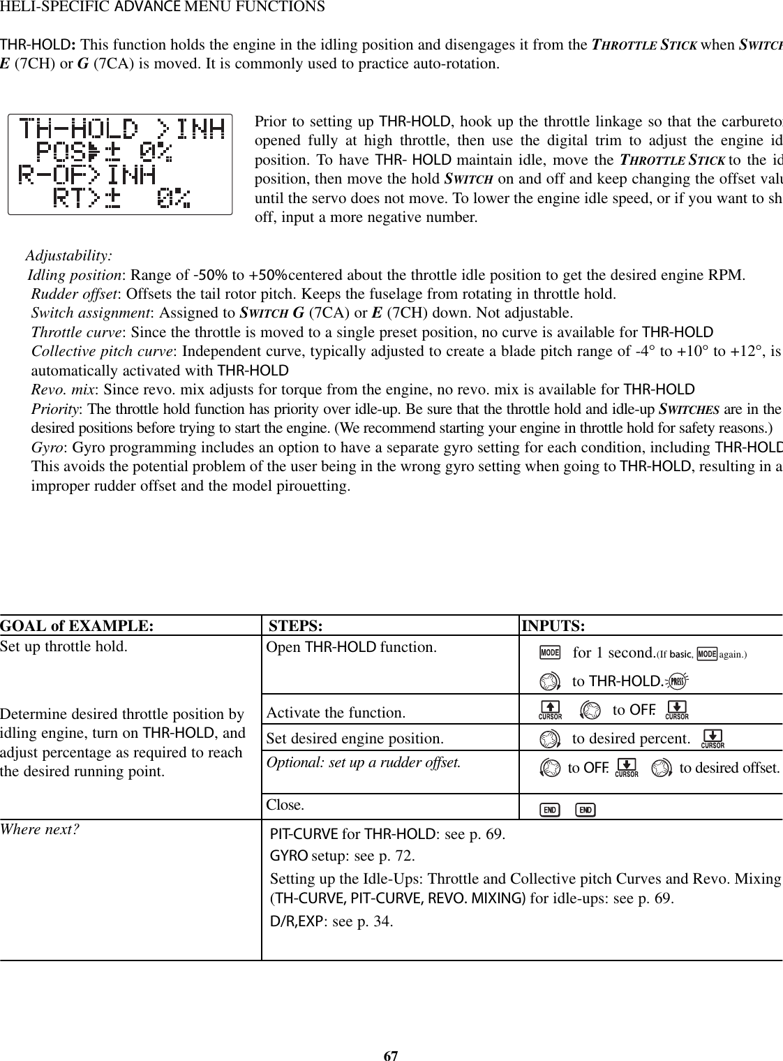
![GETTING STARTED WITH A BASIC HELICOPTERThis guideline is intended to help you set up a basic ( H-1 ) heli, to get acquainted with the radio, to give you a jump starton using your new radio, and to give you some ideas and direction on how to do even more with this powerful system thanyou may have already considered. It follows our basic format of all programming pages: a big picture overview of whatwe're trying to accomplish; a "by name" description of the steps to help acquaint you with the radio; and then a step-by-step instruction to leave out the mystery and challenge of setting up your model.Briefly, the typical helicopterís controls are as follows:Aileron: changes cyclic lateral (roll) . Rolls the helicopter. Tilts the swashplate to the left or right. CH1.Elevator: changes cyclic pitch. Changes the helicopterís angle of attack (nose up or nose down). Tilts the entireswashplate fore and aft. CH2.Rudder: changes the angle of the tail rotor. Yaws the helicopter left or right. CH4.Collective Pitch: adjusts main rotor collective [angle of the paddles], changing the main bladesí pitch. Increased collectivepitch (with throttle) causes the helicopter to rise. Moves in conjunction with throttle on the THROTTLE STICK.CH6.Throttle: opens/closes carburetor. Moves in conjunction with collective pitch on the THROTTLE STICK.CH3.REVO: mix that adds rudder in conjunction with pitch. This helps compensate for rotation of the helicopter caused bythe increased engine torque. (Never use revo. mixing with a heading-hold/AVCS gyro which is in heading-hold/AVCS mode. However, revo. mixing is still used when a heading-hold/AVCS gyro is in normal mode.)For additional details, see that function's section in this manual. The page numbers are indicated in the first column for you.GOAL of EXAMPLE: STEPS: INPUTS:58Prepare your helicopter.Select the proper MODEL TYPE for yourmodel. Ex: HELI ( H-1) . See p. 61.[NOTE: This is one of severalfunctions for which the radio requiresconfirmation to make a change. Onlycritical changes require additionalkeystrokes to accept the change.](If the correct model type was alreadydisplayed, be sure to do a model resetto discard any unwanted settings.)Then, NAME the model. P. 25.(You do not need to do anything to"save" or stor e this data.)In the BASIC menu, open thePARAMETER submenu.Go to MODEL TYPE.Select proper MODEL TYPE.Ex: H-1.Confirm the change. Close PARAMETER.In the BASIC menu, open the MODELsubmenu.Go to MODEL NAME.Input aircraft's name.Close the MODEL submenu when done.Turn on the transmitter.for 1 second.(If ADVANCE, again.)to highlight PARAMETER.to choose PARAMETER.to TYPE.to H-1.for1second.sure?displays. to confirm.to return to BASIC menu.as needed to highlight MODEL.to choose MODEL.(First character of model'sname is highlighted.)to change first character.When proper character is displayed,to move to next character. Repeat.to return to BASIC menu.Install all servos, switches, receiver per your model's instructions. Set all trimsand dials to neutral.Confirm all control linkages are 90 degrees (or per instructions) from the servohorn to the ball link for proper geometry and that no slop is present.Mechanically adjust all linkages to get as close as possible to proper controlthrows and minimize binding prior to radio set up.••••••](https://usermanual.wiki/Futaba/T7C-72/User-Guide-388589-Page-58.png)
![GOAL of EXAMPLE: STEPS: INPUTS:1Radio emits a repeating "beep" and shows progress on screen as the model memory is being copied. Note that if the power switch is turned off priorto completion, the data will not be copied.62Change the MODEL TYPE of model #3from aircraft to 120 degree CCPM with 2servos working in unison for collectivepitch and aileron [HELI(HR3) ].Where next?Confirm you are currently using theproper model memory. (example: 3)Open PARAMETER submenu.Change to the desired MODELTYPE(example, HR3.)Confirm the change.Close.On home screen, check model nameand # on top left and right.If it is not the correct model (example:3), see MODEL SELECT,p.25.for 1 second.(If ADVANCE, again.)to PARAMETER.to HR3.for one second."sure?" displays. to confirm.1If a single servo is not operating properly, REVERSE:seep. 31.If a control is operating backwards (i.e. Elevator), see SWASH AFR,p.63.If unsure seeSWASH AFR.](https://usermanual.wiki/Futaba/T7C-72/User-Guide-388589-Page-62.png)
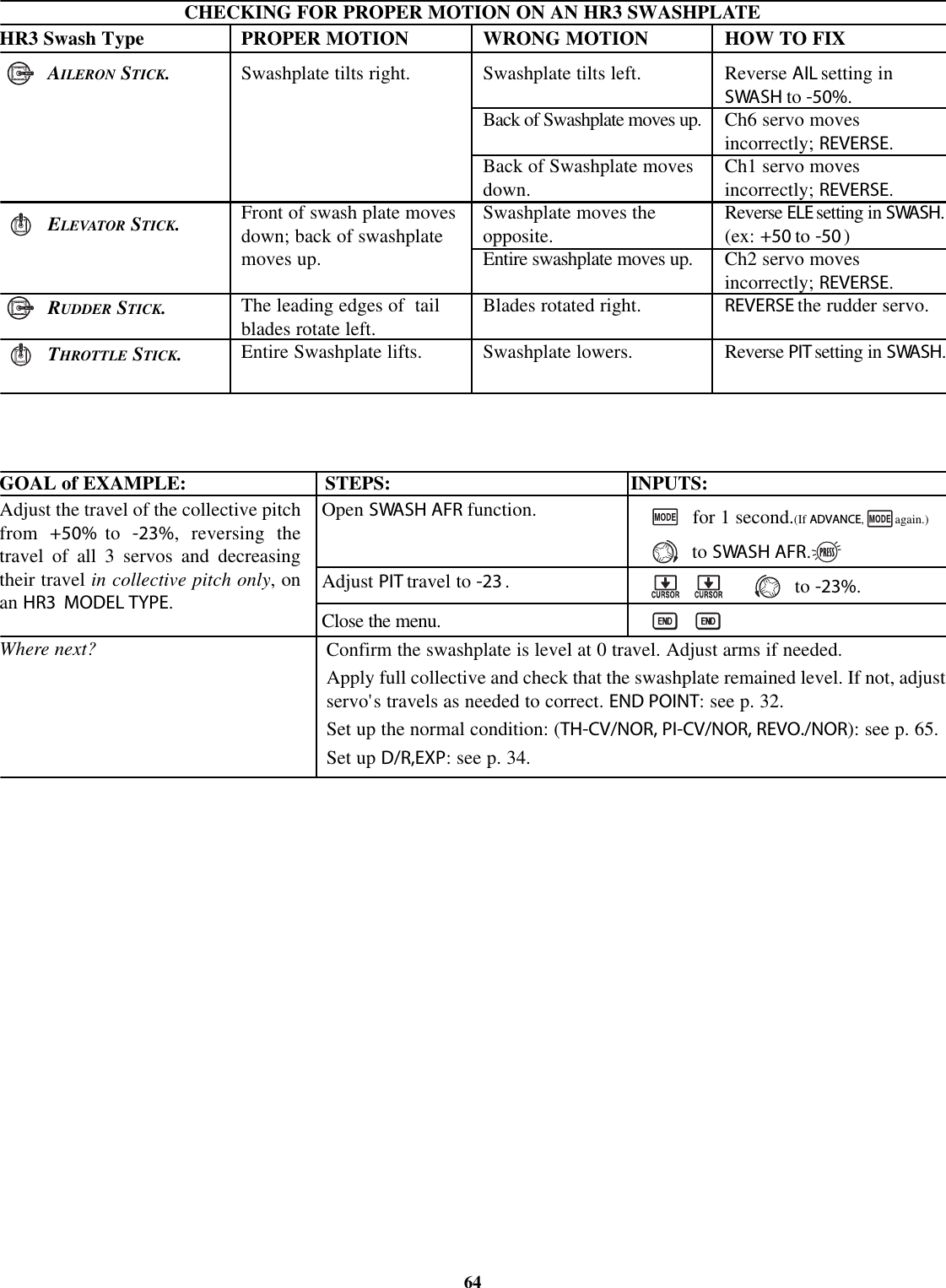
![SWASH AFR [HELI(H-2/HE3/HR3/H-3/HN3)only]:Swashplate function rate settings (SWASH AFR) reduce/increase/reverse the rate (travof the aileron, elevator (except H-2 ) and collective pitch functions, adjusting oreversing the motion of all servos involved in that function, only when using thfunction. Since these types utilize multiple servos together to create the controls, simpadjusting a servo's REVERSE or END POINT would not properly correct the travel of aone control. Since H-1uses one servo for each function, there is no need for AFR in H-1This is fairly hard to explain but easy to see, so letís set up Kyosho Caliber's swashplate settings as an example. Witheverything installed per factory instructions, set the model to HELI(HR3) .Now let's adjust the swashplate properly.Since aileron always uses no more than 2 servos, check it first. Either both operate properly (no change needed), bothoperate backwards (reverse the whole function), or one servo operates backwards (reverse that servo alone).Next check elevator. Remember, the aileron servo(s) operate correctly, so if elevator does not, we should only have 2choices left - the whole function needs to be reversed, or the servo(s) not shared with aileron need to be reversed.Last is collective. If aileron and elevator are working properly, the only thing that could be wrong is the whole directioncollective operates (reverse the whole function). In our example, HR3 is 180 degrees off from the swashplate of the Caliber.Therefore, it is very likely that several functions will not operate properly. The collective pitch operation is backwards; butreversing all three servos would also reverse the aileron and elevator operations. Changing the collective pitch rate,however, from +50%to -50%, will reverse the collective pitch without affecting the aileron action.63](https://usermanual.wiki/Futaba/T7C-72/User-Guide-388589-Page-63.png)
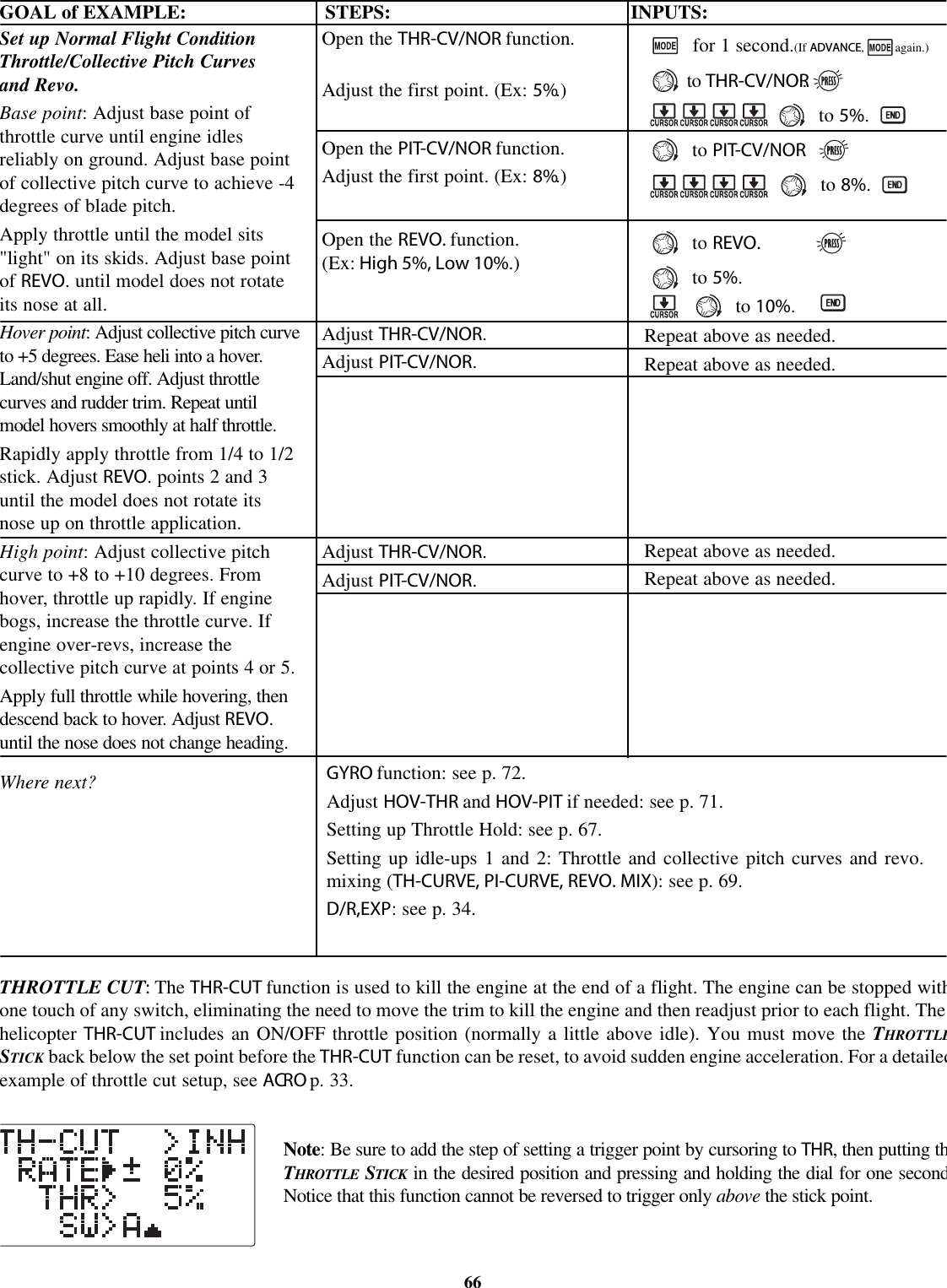
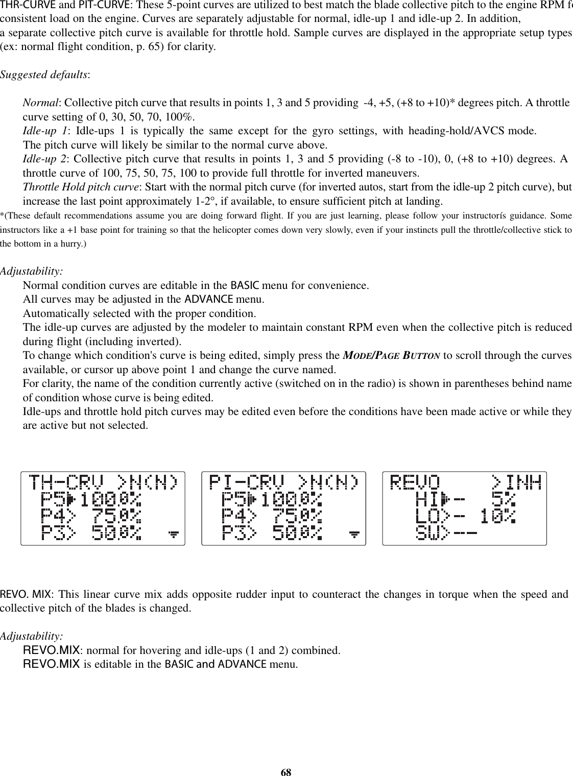
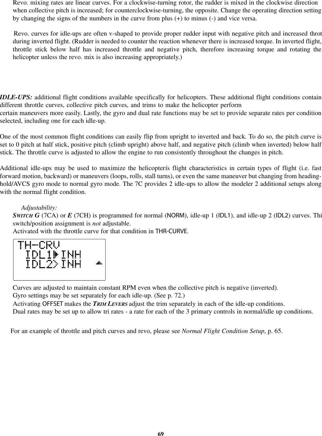
![Setting up the Normal Flight Condition: The Normal flight condition is typically utilized for hovering. The throttle andcollective pitch curves are adjusted to provide consistent engine RPM despite the increase/decrease in collective pitch ofthe blades. This keeps the engine from "bogging down" under excessive load (like trying to accelerate a car on a steep hillin 5th gear) or excessive RPM under insufficient load (like flooring the throttle while in neutral), risking engine damage.As the 2 curves and revo. mixing are all interrelated, we will discuss all three first, then complete a sample setup.Note that the normal throttle and pitch curves and revo mix are all available in the BASIC menu for simplicity. These may also beupdated later in the ADVANCE menu with the settings for the other 3 conditions [idle-up 1 (IDL1), idle-up 2 (IDL2)andthrottle hold (HOLD)]. Note:The throttle and pitch curves for the normal condition are always on. They cannot be inhibited. Theother three conditions are activated with their throttle curves or throttle hold. For idle-ups, see p. 69. For throttle hold, see p. 67.TH-CV/NOR: inputs the normal (NORM) throttle curve, which is usually not a linear response to THROTTLE STICK motionAdjusting point 3 of the curve adjusts the engine's RPM at the THROTTLE STICK midpoint - the desired position forhovering. The other 4 points are then adjusted to create the desired idle and maximum engine speed, and a smoothtransition in-between. For more on throttle curves, see p. 69.PI-CV/NOR: inputs the normal (NORM) collective pitch curve, the collective pitch curve for flight near hover. Thenormal collective pitch curve is adjusted to match the throttle curve, providing the best vertical performance at aconstant engine speed, with a starting curve of -4 base, +5 neutral, and +8 to +10 degrees of blade pitch maximum*.You can program the response over a 5-point curve for the best collective pitch angle relative to THROTTLE STICKmovement. For more on collective pitch curves, see p. 69.REVO.:mixes collective pitch commands to the rudder (a PITCH-RUDDER mix) to suppress the torque generated bychanges in the main rotor's collective pitch angle, keeping the model from yawing when throttle is applied. REVO.is extremely helpful in "taming the tail" of models not using heading-hold/AVCS gyros. Never use revo. mixingin conjunction with a heading-hold/AVCS gyro while in heading-hold/AVCS mode.Revo. mixing is still used with these gyros while set to the normal mode. For details on revo, including default pointsfor clockwise and counterclockwise rotating rotors, see p. 69.*These default recommendations assume you are doing forward flight. If you are just learning, please follow your instructor's guidance. Someinstructors like a +1 base point for training so that the helicopter comes down very slowly, even if your instincts pull the throttle/collective stick tothe bottom in a hurry.65](https://usermanual.wiki/Futaba/T7C-72/User-Guide-388589-Page-65.png)
![Linear Mix: a mix that maintains the same relationship of master to slave throughout the whole range. Ex: a mix fromone flap servo to another flap servo at 100% causes the 2nd servo to follow the first servo's movement exactly throughall points of travel. See Programmable mix.Lithium battery: see Backup battery.Low Band: 72MHz equipment on a channel from 11 to 35. Receiver channel may be changed to any channel within thelow band without needing retuning. ...............................................................8LOW BATTERY warning: transmitter's battery is below a safe flight voltage. Recharge immediately. See Error messages.Low rate: see D/R, EXP.Master: the primary control. See Programmable mix.Mechanical gyro: uses a mechanical gyroscope (like a child's toy gyro) to sense change of angle. See Gyros.MHz: Megahertz. Unit used to express frequency. 72MHz channels are aircraft only frequencies; 75MHz are ground modelonly frequencies; 27MHz are air and ground both. 50MHz is legal for HAM amateur license holders. See Frequency.Mix, mixing rate, mix offset: See Programmable mix.MIXER ALERT warning: notifies user that a mix is activated which is not considered desirable for engine startup. SeeError messages.Mode: definition of which channels are assigned to which STICK movements. All 7C radios shipped in the US are Mode2, with elevator and aileron on the right STICK.Tochange mode, please visit www.futaba-rc.com.MODE/PAGE BUTTON: control button on radio's face used in various parts of programming. . . . . . . . . . . . . . . . . . . . . .11MODEL COPY: used to duplicate the settings of one model already in memory into a second model memory. Often usedto set up 2 similar models, or make a copy of a working model to experiment with new setups. . . . . . . . . . . . . . . . . 26MODEL NAME: gives each model memory an 6-character name for easy recognition. In MODEL submenu. . . . . . . . . .27MODEL RESET:restore all data in a single model memory to defaults, including name and model type. See RESET.MODEL SELECT: choose the model memory you wish to modify or fly. In MODEL submenu. . . . . . . . . . ..........25MODEL TYPE: select the type of model the aircraft is, including airplane and 6 heli types. . . . . . . .............28MODUL: modulation, means of transmitting data (PPM, PCM). In PARAMETER submenu. . . . . . . . . . . . . . . . .......31Name: see MODEL NAME.Neckstrap: optional strap to suspend transmitter during use. Futaba stock # FTA8. See Accessories.79Ni-Cd: Nickel Cadmium rechargeable battery. Typically used to power transmitter and receiver. See Battery careand charging.NiMH: Nickel Metal Hydride rechargeable battery. Newer battery technology than Ni-Cd. Longer run times but more specificpeak charging requirements. [Require a (zero) delta peak charger labeled specifically for use with NiMH batteries.]NORMAL(N): trainer mode that does not give student radio the computer programming features of the master radio. See TrainerNT8S: standard transmitter battery pack. See Accessories.NULL(--): not assigned or never changed. Ex: a mix which has a null switch assignment is always active, and can never bechanged in flight (turned off) no matter which switch is moved.](https://usermanual.wiki/Futaba/T7C-72/User-Guide-388589-Page-79.png)