User's Manual

78J-2.4G
8-CHANNEL RADIO CONTROL SYSTEM
INSTRUCTION MANUAL
Technical updates and additional programming examples available at: http://www.futaba-rc.com/faq
Entire Contents © 2012
1M23N26602
2
Introduction.............................................................3
Service ......................................................................3
Usage Precautions ...................................................4
&RQWHQWVDQGWHFKQLFDOVSHFL¿FDWLRQV....................8
Transmitter controls .............................................10
Transmitter batteries ............................................12
Switch assignment table .......................................12
Receiver and servo connections ...........................14
Charging batteries ...............................................15
Adjusting the length of the control sticks ...........16
Range check the radio ..........................................17
Radio Installation..................................................18
Link procedure .....................................................21
S.BUS Installation.................................................22
Transmitter displays & buttons ...........................21
Warning & error displays ....................................24
Map of ACRO functions.......................................26
Programming the T8J-2.4GHz Radio .................27
(Common Functions)
Model Select .....................................................27
Model Copy ......................................................27
Model Data Reset...............................................28
Model Name ......................................................29
Parameter ...........................................................30
Model Type ........................................................30
RX select (S-FHSS /FHSS) ...............................31
ATL ....................................................................32
LED adjustment .................................................32
Battery Type.......................................................33
Model Data Transmission .................................34
Reverse ..............................................................35
End Point ..........................................................36
Idle Down ..........................................................37
Throttle Cut........................................................38
D/R,EXP ............................................................39
Timer..................................................................42
AUX CH ............................................................43
Trainer................................................................44
Trim....................................................................45
Sub Trim ............................................................46
Servo ..................................................................47
Fail Safe .............................................................48
Flaperon (ACRO Only) .....................................50
Flap Trim (ACRO Only)....................................51
AIL DIFF (ACRO Only) ...................................52
Elevon (ACRO Only) ........................................53
Ailevator (ACRO Only) ....................................54
V-Tail (ACRO Only)..........................................55
Snap-Roll (ACRO Only) ...................................56
ELE-FLAP (ACRO Only) .................................59
Airbrake (ACRO Only) .....................................61
THR →Needle ..................................................62
THR Delay (ACRO Only) .................................63
THR-Curve (ACRO Only) ................................64
PIT-Curve (ACRO Only)...................................64
Programmable MIX ...........................................65
Gyro Sens (ACRO Only) ..................................64
Swashplate Types (HELI only)..........................73
Swash AFR (HELI only) ..................................75
Swash MIX (HELI only) ..................................76
THR MIX (HELI only).....................................77
Swash Ring (HELI only) ..................................77
Flight Condition<Idle-up,THR-hold> (HELI
only)...................................................................78
THR Curve (HELI only)...................................81
PIT Curve (HELI only).....................................81
REVO.MIX (HELI only)..................................81
Offset (HELI only)............................................83
Delay (HELI only)............................................84
HOV-THR (HELI only)....................................85
HOV-PIT (HELI only)......................................85
HI/LO-PIT (HELI only)....................................86
Gyro (HELI only) .............................................87
Governor (HELI only) ......................................89
TX Setting.........................................................91
TABLE OF CONTENTS
3
INTRODUCTION
Thank you for purchasing a Futaba® S-FHSS-2.4GHz*8J series digital proportional R/C system. This system
is extremely versatile and may be used by beginners and pros alike. In order for you to make the best use of
\RXUV\VWHPDQGWRÀ\VDIHO\SOHDVHUHDGWKLVPDQXDOFDUHIXOO\,I\RXKDYHDQ\GLI¿FXOWLHVZKLOHXVLQJ\RXU
system, please consult the manual, our online Frequently Asked Questions (on the web pages referenced
below), your hobby dealer, or the Futaba Service Center.
*S-FHSS: Super- Futaba Frequency Hopping Spread Spectrum
Owner’s Manual and Additional Technical Help
This manual has been carefully written to be as helpful to you, the new owner, as possible. There are many
pages of setup procedures and examples. However, it need not be your sole resource of setup guidelines for
your 8J. For example, pages 27-29 include setup instructions for a basic 4-channel airplane. The Frequently
Asked Questions web page referenced below includes this type of step-by-step setup instructions for a
variety of other model types, including multi-engine, complex gear installation, 7-servo aerobatic models,
140 degree CCPM, etc.
http://www.futaba-rc.com/faq
Due to unforeseen changes in production procedures, the information contained in this manual is subject to
change without notice.
Support and Service: It is recommended to have your Futaba equipment serviced annually during your
hobby’s “off season” to ensure safe operation.
IN NORTH AMERICA
Please feel free to contact the Futaba Service Center for assistance in operation, use and programming. Please
be sure to regularly visit the 8J Frequently Asked Questions web site at www.futaba-rc.com/faq/. This page
includes extensive programming, use, set up and safety information on the 8J radio system and is updated
regularly. Any technical updates and US manual corrections will be available on this web page. If you do not
¿QGWKHDQVZHUVWR\RXUTXHVWLRQVWKHUHSOHDVHVHHWKHHQGRIRXU)$4DUHDIRULQIRUPDWLRQRQFRQWDFWLQJ
us via email for the most rapid and convenient response.
Don’t have Internet access? Internet access is available at no charge at most public libraries, schools, and
RWKHUSXEOLFUHVRXUFHV:H¿QGLQWHUQHWVXSSRUWWREHDIDEXORXVUHIHUHQFHIRUPDQ\PRGHOHUVDVLWHPVFDQ
be printed and saved for future reference, and can be accessed at any hour of the day, night, weekend or
holiday. If you do not wish to access the internet for information, however, don’t worry. Our support teams
are available Monday through Friday 8-5 Central time to assist you.
FOR SERVICE ONLY:
Futaba Service Center
3002 N. Apollo Drive, Suite 1
Champaign, IL 61822
Phone: 217-398-0007
www.futaba-rc.com/service.html
Email: service@futaba-rc.com
FOR SUPPORT :
(PROGRAMMING AND USER QUESTIONS)
Please start here for answers to most questions:
www.futaba-rc.com/faq/
FACSIMILE: 217-398-7721
PHONE: 217-398-8970 option 2
OUTSIDE NORTH AMERICA
Please contact your Futaba importer in your region of the world to assist you with any questions, problems or
service needs.
Please recognize that all information in this manual, and all support availability, is based upon the systems
sold in North America only. Products purchased elsewhere may vary. Always contact your region’s support
center for assistance.
4
$SSOLFDWLRQ([SRUWDQG0RGL¿FDWLRQ
1. This product may be used for model airplane or surface (boat, car, robot) use. It is not intended for use in
any application other than the control of models for hobby and recreational purposes. The product is subject to
regulations of the Ministry of Radio/Telecommunications and is restricted under Japanese law to such purposes.
2. Exportation precautions:
(a) When this product is exported from the country of manufacture, its use is to be approved by the laws
governing the country of destination which govern devices that emit radio frequencies. If this product is then re-
exported to other countries, it may be subject to restrictions on such export. Prior approval of the appropriate
government authorities may be required. If you have purchased this product from an exporter outside your
country, and not the authorized Futaba distributor in your country, please contact the seller immediately to
determine if such export regulations have been met.
(b) Use of this product with other than models may be restricted by Export and Trade Control Regulations, and
an application for export approval must be submitted. This equipment must not be utilized to operate equipment
other than radio controlled models.
0RGL¿FDWLRQDGMXVWPHQWDQGUHSODFHPHQWRISDUWV)XWDEDLVQRWUHVSRQVLEOHIRUXQDXWKRUL]HGPRGL¿FDWLRQ
adjustment, and replacement of parts on this product. Any such changes may void the warranty.
Federal Communications Commission Interference Statement (for U.S.A.)
This equipment has been tested and found to comply with the limits for a Class B digital device, pursuant to Part
15 of the FCC Rules. These limits are designed to provide reasonable protection against harmful interference in
a residential installation.
This equipment generates, uses and can radiate radio frequency energy and, if not installed and used in
accordance with the instructions, may cause harmful interference to radio communications. However, there is
no guarantee that interference will not occur in a particular installation. If this equipment does cause harmful
interference to radio or television reception, which can be determined by turning the equipment off and on, the
user is encouraged to try to correct the interference by one or more of the following measures:
--Reorient or relocate the receiving antenna.
--Increase the separation between the equipment and receiver.
--Connect the equipment into an outlet on a circuit different from that to which the receiver is connected.
--Consult the dealer or an experienced radio/TV technician for help.
CAUTION:
To assure continued FCC compliance:
Any changes or modifications not expressly approved by the grantee of this device could void the user's
authority to operate the equipment.
Exposure to Radio Frequency Radiation
To comply with FCC RF exposure compliance requirements, a separation distance of at least 20cm must be
maintained between the antenna of this device and all persons.
This device must not be co-located or operating in conjunction with any other antenna or transmitter.
Compliance Information Statement (for U.S.A.)
This device, trade name Futaba Corporation of America, model number R2008SB, complies with part15 of the
FCC Rules. Operation is subject to the following two conditions:
(1) This device may not cause harmful interference, and
(2) This device must accept any interference received, including interference that may cause undesired
operation.
The responsible party of this device compliance is:
Futaba Service Center
3002 N Apollo Drive Suite 1, Champaign, IL 61822 U.S.A.
TEL (217)398-8970 or E-mail: support@futaba-rc.com (Support)
TEL (217)398-0007 or E-mail: service@futaba-rc.com (Service)

5
Meaning of Special Markings
Pay special attention to safety where indicated by the following marks:
DANGER - Procedures which may lead to dangerous conditions and cause death/serious injury if not
carried out properly.
WARNING - Procedures which may lead to a dangerous condition or cause death or serious injury
WR WKH XVHU LI QRW FDUULHG RXW SURSHUO\ RU SURFHGXUHV ZKHUH WKH SUREDELOLW\ RI VXSHU¿FLDO LQMXU\ RU
physical damage is high.
CAUTION - Procedures where the possibility of serious injury to the user is small, but there is a
danger of injury, or physical damage, if not carried out properly.
= Prohibited = Mandatory
Warning: Always keep electrical components away from small children.
FLYING SAFETY
WARNING
To ensure the safety of yourself and others, please observe the following precautions:
Have regular maintenance performed. Although your 8J protects the model memories with
non-volatile EEPROM memory (which does not require periodic replacement) and not a battery, the
transmitter still should have regular checkups for wear and tear. We recommend sending your system
WR WKH )XWDED 6HUYLFH &HQWHU DQQXDOO\ GXULQJ \RXU QRQÀ\LQJVHDVRQ IRU D FRPSOHWH FKHFNXS DQG
service.
NiCd Battery
Charge the batteries! (See Charging the NiCd batteries, p. 15, for details.) Always recharge the
WUDQVPLWWHUDQG UHFHLYHUEDWWHULHV IRUDWOHDVWKRXUV EHIRUHHDFK À\LQJVHVVLRQ$ ORZEDWWHU\ZLOO
VRRQGLHSRWHQWLDOO\FDXVLQJORVVRIFRQWURODQGDFUDVK:KHQ\RXEHJLQ\RXUÀ\LQJVHVVLRQUHVHW
your 8J’s built-in timer, and during the session pay attention to the duration of usage.
6WRSÀ\LQJORQJEHIRUH\RXUEDWWHULHVEHFRPHORZRQFKDUJH'RQRWUHO\RQ\RXUUDGLR¶VORZ
battery warning systems, intended only as a precaution, to tell you when to recharge. Always
FKHFN\RXUWUDQVPLWWHUDQGUHFHLYHUEDWWHULHVSULRUWRHDFKÀLJKW
Where to Fly
:H UHFRPPHQG WKDW \RX À\ DW D UHFRJQL]HG PRGHO DLUSODQH À\LQJ ¿HOG<RX FDQ ¿QG PRGHO FOXEV DQG
¿HOGVE\DVNLQJ\RXUQHDUHVWKREE\GHDOHURULQWKH86E\FRQWDFWLQJWKH$FDGHP\RI0RGHO$HURQDXWLFV
<RX FDQ DOVR FRQWDFW WKH QDWLRQDO$FDGHP\ RI 0RGHO$HURQDXWLFV $0$ ZKLFK KDV PRUH WKDQ
chartered clubs across the country. Through any one of them, instructor training programs and insured
newcomer training are available. Contact the AMA at the address or toll-free phone number below.
Academy of Model Aeronautics
5161 East Memorial Drive
Muncie, IN 47302
Tele. (800) 435-9262
Fax (765) 289-4248
or via the Internet at http:\\www.modelaircraft.org

6
$OZD\V SD\ SDUWLFXODU DWWHQWLRQ WR WKH À\LQJ ¿HOG¶V UXOHV as well as the presence and location
RIVSHFWDWRUVWKHZLQGGLUHFWLRQDQGDQ\REVWDFOHVRQWKH¿HOG%HYHU\FDUHIXOÀ\LQJLQDUHDVQHDU
power lines, tall buildings, or communication facilities as there may be radio interference in their
vicinity.
,I\RXPXVWÀ\DZD\IURPDFOXE¿HOGEHVXUHWKHUHDUHQRRWKHUPRGHOHUVÀ\LQJZLWKLQDWKUHHWR¿YH
mile range, or you may lose control of your aircraft or cause someone else to lose control.
$WWKHÀ\LQJ¿HOG
To prevent possible damage to your radio gear, turn the power switches on and off in the proper sequence:
1. Pull throttle stick to idle position, or otherwise disarm your motor/engine.
2. Turn on the transmitter power and allow your transmitter to reach its home screen.
&RQ¿UPWKHSURSHUPRGHOPHPRU\KDVEHHQVHOHFWHG
4. Turn on your receiver power.
7HVWDOOFRQWUROV,IDVHUYRRSHUDWHVDEQRUPDOO\GRQ¶WDWWHPSWWRÀ\XQWLO\RXGHWHUPLQHWKHFDXVHRIWKH
problem.
7HVWWRHQVXUHWKDWWKH)DLOVDIHVHWWLQJVDUHFRUUHFW$IWHUDGMXVWLQJWXUQWKHWUDQVPLWWHURIIDQGFRQ¿UP
the proper surface/throttle movements. Then turn the transmitter back on.
6. Start your engine.
7. Complete a full range check (see p. 22).
$IWHUÀ\LQJEULQJ\RXUWKURWWOHVWLFNWRLGOHSRVLWLRQHQJDJHDQ\NLOOVZLWFKHVRURWKHUZLVHGLVDUP\RXU
motor/engine.
9. Turn off receiver power.
10. Turn off transmitter power.
,I\RXGRQRWWXUQRQ\RXUV\VWHP LQWKLV RUGHU \RXPD\ GDPDJH\RXUVHUYRVRUFRQWUROVXUIDFHVÀRRG
your engine, or in the case of electric-powered or gasoline-powered models, the engine may unexpectedly
turn on and cause a severe injury.
:KLOH\RXDUHJHWWLQJUHDG\WRÀ\LI\RXSODFH\RXUWUDQVPLWWHURQWKHJURXQGEHVXUHWKDWWKH
wind won't tip it over. If it is knocked over, the throttle stick may be accidentally moved, causing
the engine to speed up. Also, damage to your transmitter may occur.
In order to maintain complete control of your aircraft it is important that it remains visible at all
times. Flying behind large objects such as buildings, grain bins, etc. is not suggested. Doing so may
result in the reduction of the quality of the radio frequency link to the model.
Do not cover/hold the built-in antenna part of T8J-2.4G transmitter by your hand during
À\LQJ Do not put any conductive plate/sticker on the antenna part. Otherwise, the operating range
may become shorter.
As with all radio frequency transmissions, the strongest area of signal transmission is from the sides
of the transmitter's antenna. As such, the antenna should not be pointed directly at the model. If your
À\LQJVW\OHFUHDWHVWKLVVLWXDWLRQHDVLO\PRYHWKHDQWHQQDWRFRUUHFWWKLVVLWXDWLRQ
Don’t fly in the rain! Water or moisture may enter the transmitter through the antenna or stick
openings and cause erratic operation or loss of control. If you must fly in wet weather during a
contest, be sure to cover your transmitter with a plastic bag or waterproof barrier. Never fly if
lightning is expected.

7
A QUICK INTRODUCTION TO THE 8J SYSTEM
TRANSMITTER:
/DUJH JUDSKLF OLTXLGFU\VWDO GLVSOD\ SDQHO ZLWK WKUHH EXWWRQV DQ HDV\ VHW XS WXUQDQGSUHVV MRJNH\ IRU
quick, easy setup.
$OOWUDQVPLWWHUVLQFOXGHERWKDLUFUDIWW\SHVZLWKVSHFLDOL]HGSURJUDPPLQJIRUHDFKLQFOXGLQJ
$LUSODQHACRO)
V-TAIL 7ZLQ$LOHURQ6HUYRVFLAPERON and AIL-DIFF *\UR0L[LQJ
ELEVON 7ZLQ(OHYDWRU6HUYRVAILEVATOR)
AIRBRAKE 6QDS5ROOVHSDUDWHGLUHFWLRQVDYDLODEOH
+HOLFRSWHUVZDVKSODWHW\SHVLQFOXGLQJ&&30VHHSDJHHELI)
,GOH8SV 7KURWWOHDQG3LWFK&XUYHVSHU&RQGLWLRQ
5HYR0L[LQJ *\UR0L[LQJLQFOXGLQJ6HSDUDWH6HWWLQJVSHU&RQGLWLRQ
'HOD\ *RYHUQRU0L[LQJ
)RXU HOHFWURQLFTRIM LEVERS for rapid yet precise trim adjustment - no remembering to “store trims”
between models and no more “bumped trims” during transport.
IDLE- DOWN (ACRO), THR-CUT (ACRO/HELI) (engine shut off), setups to allow precise engine/motor control for
taxi and landings.
FRPSOHWHPRGHOPHPRULHV
1HZVWLFNGHVLJQZLWKLPSURYHGIHHODGMXVWDEOHOHQJWKDQGWHQVLRQ
7ZRUDWHVDYDLODEOHE\VHWWLQJGXDOUDWHVWRSRVLWLRQVZLWFKHV
(LJKWSWITCHES, and DIAL; completely assignable in most applications.
7UDLQHUV\VWHPLQFOXGHVWKH³IXQFWLRQDO´FUNC) setting, which allows the student to use the 8J’s mixing,
helicopter, and other programming functions even with a 4-channel buddy box. (Optional trainer cord
required.)
3HUPDQHQWPHPRU\VWRUDJHYLD((3520ZLWKQREDFNXSEDWWHU\WRVHUYLFHRUKDYHIDLO
-$WUDQVPLWWHUIHDWXUHVDLUSODQHIULHQGO\VZLWFKOD\RXWZLWKWKHWUDLQHUVZLWFKDWWKHOHIWKDQG0RGH
and a notched throttle to minimize throttle changes with rudder input. Defaults to ACRO model type.
-+WUDQVPLWWHUIHDWXUHVKHOLFRSWHUIULHQGO\VZLWFKOD\RXWZLWKLGOHXSDQGWKURWWOHKROGVZLWFKHVDWWKHOHIW
hand, and a smooth, ratchet-less (unsprung) throttle for perfect hovering. Defaults to HELI(H-1 swashplate
type) model type.
&KDQJHWUDQVPLWWHUPRGHIURPPRGHWRPRGHVRU6HH3
7KHEXLOWLQDQWHQQDZKLFKSXWVWKHDQWHQQDZLWKLQWKHWUDQVPLWWHUFDVH
7KHGLYHUVLW\V\VWHPZKLFKKDVDQWHQQDVLQWKHLQVLGHRIDWUDQVPLWWHU
Note that in the text of this manual, beginning at this point, any time we are using a feature’s specialized
name or abbreviation as seen on the screen of the 8J, that name, feature, or abbreviation will be exactly as
seen on the radio’s screen, including capitalization and shown in a DIFFERENT TYPE STYLE for clarity. Any
WLPHZHPHQWLRQDVSHFL¿FFRQWURORQWKHUDGLRLWVHOIVXFKDVPRYLQJSWITCH A,VR, or the THROTTLE
STICK, those words will be displayed as they are here.
8
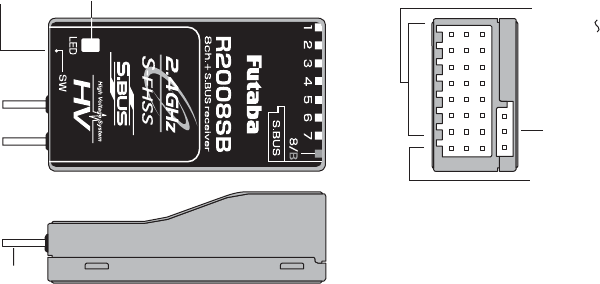
RECEIVER: R2008SB
7KH56%KDVDQ6%86V\VWHPRXWSXWSRUWDQGDFRQYHQWLRQDOV\VWHPFKDQQHORXWSXWV,WFDQDOVREH
used with conventional system servos, etc. in addition to S.BUS system compatible servos and gyros, etc.
Link switch
Antenna
LED
R2008SB
for conventional
system
Channel 1
Channel 7
Channel 8 output
for conventional
system
/Battery terminal
output
output
S.BUS Port
(Connectors)
SERVOS
3OHDVHVHHWHFKQLFDOVSHFL¿FDWLRQVSDJHIRUVSHFL¿FVRQWKHVHUYRV
7KH LQFOXGHG UHFHLYHU LV FRPSDWLEOH ZLWK DOO -SOXJ )XWDED VHUYRV LQFOXGLQJ UHWUDFW ZLQFK DQG GLJLWDO
servos.
CONTENTS AND TECHNICAL SPECIFICATIONS
6SHFL¿FDWLRQVDQGUDWLQJVDUHVXEMHFWWRFKDQJHZLWKRXWQRWLFH
Your 8J system includes the following components:
T8J Transmitter
R2008SB Receiver
6ZLWFKKDUQHVV
$LOHURQH[WHQVLRQFRUG
1HFNVWUDS
* The set contents depend on the type of set.
Transmitter T8J
(2-stick, 8-channel, S-FHSS system, Built-in
Dual Antenna Diversity)
Transmitting frequency: 2.4GHz band
Power supply: 4-AA 1.2V Dry Cell batteries; 4.8V
total (sold separately)
or HT5F1700B Ni-MH battery (option)
or FT2F2100B Li-Fe battery (option)
Receiver R2008SB
(Dual Antenna Diversity)
Power requirement: 4.8V to 7.4V battery or regulated
output from ESC, etc. (*1)
Size: 0.98 x 1.69 x 0.55 in. (24.9 x 42.8 x 14.0 mm)
Weight: 0.34 oz. (9.5g)
(*1) Be sure that when using ESC's regulated output
the capacity of the ESC must meet your usage
condition.
9
The following additional accessories are available from your dealer. Refer to a Futaba catalog for more
information:
+7)%/FT2F2100B Transmitter battery pack - the transmitter battery pack may be easily exchanged
ZLWKDIUHVKRQHWRSURYLGHHQRXJKFDSDFLW\IRUH[WHQGHGÀ\LQJVHVVLRQV
7UDLQHUFRUGWKHRSWLRQDOWUDLQHUFRUGPD\EHXVHGWRKHOSDEHJLQQLQJSLORWOHDUQWRÀ\HDVLO\E\SODFLQJ
the instructor on a separate transmitter. Note that the 8J transmitter may be connected to another 8J system,
as well as to many other models of Futaba transmitters. The 8J transmitter uses the newer micro (rectangular
type) cord plug. Both new-to-new and new-to-round plug style trainer cords are available.
1HFNVWUDSDQHFNVWUDSPD\EHFRQQHFWHGWR\RXU7-V\VWHPWRPDNHLWHDVLHUWRKDQGOHDQGLPSURYH\RXU
À\LQJSUHFLVLRQVLQFH\RXUKDQGVZRQ¶WQHHGWRVXSSRUWWKHWUDQVPLWWHU¶VZHLJKW
<KDUQHVVHVVHUYRH[WHQVLRQVKXEHWF*HQXLQH)XWDEDH[WHQVLRQVDQG<KDUQHVVHVLQFOXGLQJDKHDY\
duty version with heavier wire, are available to aid in your larger model and other installations.
FHOO 9 UHFHLYHU EDWWHU\ SDFNV $OO )XWDED DLUERUQH HTXLSPHQW H[FHSW WKDW ZKLFK LV VSHFLILFDOO\
labeled otherwise) is designed to work with 4.8V (Ni-Cd 4 cells) or 6.0V (Ni-Cd 5 cells or alkaline 4 cells).
8VLQJD9SDFNLQFUHDVHVWKHFXUUHQWÀRZWRWKHVHUYRVZKLFKDFFHOHUDWHVWKHLUUDWHRIUHVSRQVHDQGWKHLU
torque. However, because of this faster current draw, a 5-cell battery pack of the same mAh rating will last
approximately 3/4 the time of a 4-cell pack.
*\URVDYDULHW\RIJHQXLQH)XWDEDJ\URVDUHDYDLODEOHIRU\RXUDLUFUDIWRUKHOLFRSWHUQHHGV
*RYHUQRU *9*<&*<IRU KHOLFRSWHUXVH$XWRPDWLFDOO\ DGMXVWVWKURWWOHVHUYR SRVLWLRQWR
maintain a constant head speed regardless of blade pitch, load, weather, etc.
5HFHLYHUVYDULRXVPRGHOVRIUHFHLYHUVPD\EHSXUFKDVHGIRUXVHLQRWKHUPRGHOV2QO\*+]6)+66
FHSS Type)
10
7KLV¿JXUHVKRZVWKHGHIDXOWVZLWFKDVVLJQPHQWVIRUD-$0RGHV\VWHPDVVXSSOLHGE\WKHIDFWRU\
<RXFDQFKDQJHPDQ\RIWKHVZLWFKSRVLWLRQVRUIXQFWLRQVE\VHOHFWLQJDQHZSRVLWLRQZLWKLQ
the setting menu for the function you wish to move.
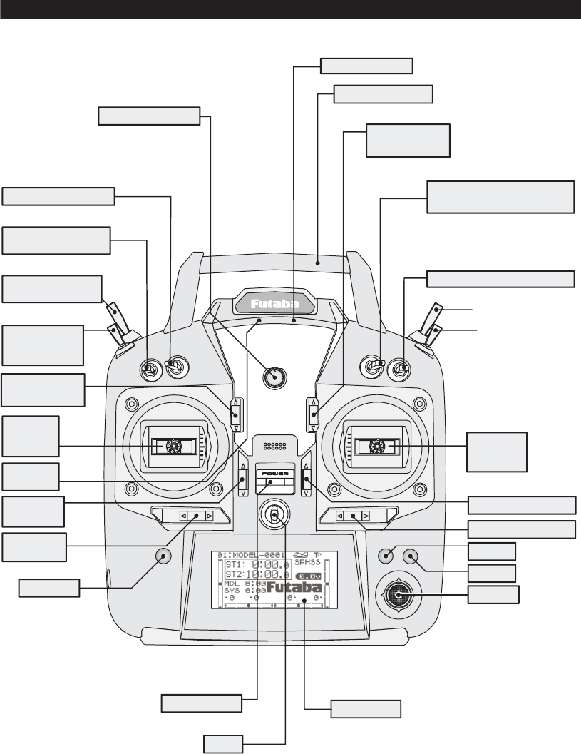
TRANSMITTER CONTROLS - AIRPLANE
SW(B)
VR
SW(A)
SW(F)
SW(E)
SW(G)
SW(H)
SW(D)
SW(C)
This controls CH6, and if flaperon mixing
is activated controls the flap.
Flap Trim Control
Rudder Dual Rate Switch
Elevator Dual Rate
Snap Roll or
Trainer Switch
Landing Gear
Switch
/CH5
Rudder
/Throttle
Stick
Power
LED*
Throttle
Trim Lever
Rudder
Trim Lever
END Key − Key
+ Key
Aileron Trim Lever
Elevator Trim Lever
Elevator
/Aileron
Stick
Aileron Dual Rate Switch
Elevator - Flap Mixing or
Airbrake Mixing Switch
Digital Trim 6
/CH8 Control
Digital Trim 5
/CH7 Control
Carrying Handle
Built-in Antenna
Switch
Jog Key
LCD Panel
Power Switch
(Up position: ON)
Hook
(for optional neckstrap)
11
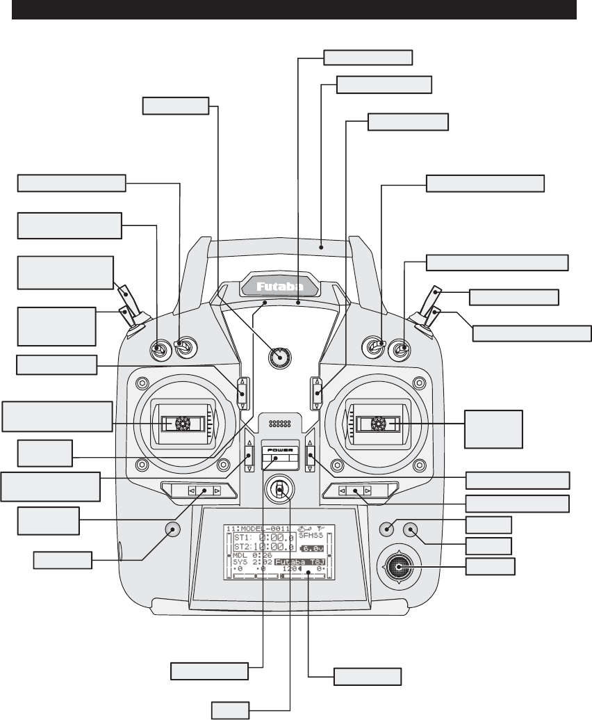
7KLV¿JXUHVKRZVWKHGHIDXOWVZLWFKDVVLJQPHQWVIRUD-+0RGHV\VWHPDVVXSSOLHGE\WKHIDFWRU\
<RXFDQFKDQJHPDQ\RIWKHVZLWFKSRVLWLRQVRUIXQFWLRQVE\VHOHFWLQJDQHZSRVLWLRQZLWKLQ
the setting menu for the function you wish to move.
TRANSMITTER CONTROLS - HELI
VR
CH8 Knob
SW(B)
SW(A)
SW(F)
SW(E)
SW(G)
SW(H)
SW(D)
SW(C)
Rudder Dual Rate Switch
Elevator Dual Rate
Power
LED
Rudder
Trim Lever
END Key − Key
+ Key
Aileron Trim Lever
Elevator Trim Lever
Elevator
/Aileron
Stick
Aileron Dual Rate Switch
Digital Trim 6
Digital Trim 5
Carrying Handle
Built-in Antenna
Switch
Jog Key
Idle-up 3 Switch
/Gyro/CH5
Idle-up 1&2
Switch
Throttle/Collective
Pitch & Rudder Stick
Pitch Trim Lever
Throttle/Collective
Governor Switch/CH7
Trainer Switch
Throttle - Hold Switch
LCD Panel
Power Switch
(Up position: ON)
Hook
(for optional neckstrap)
12
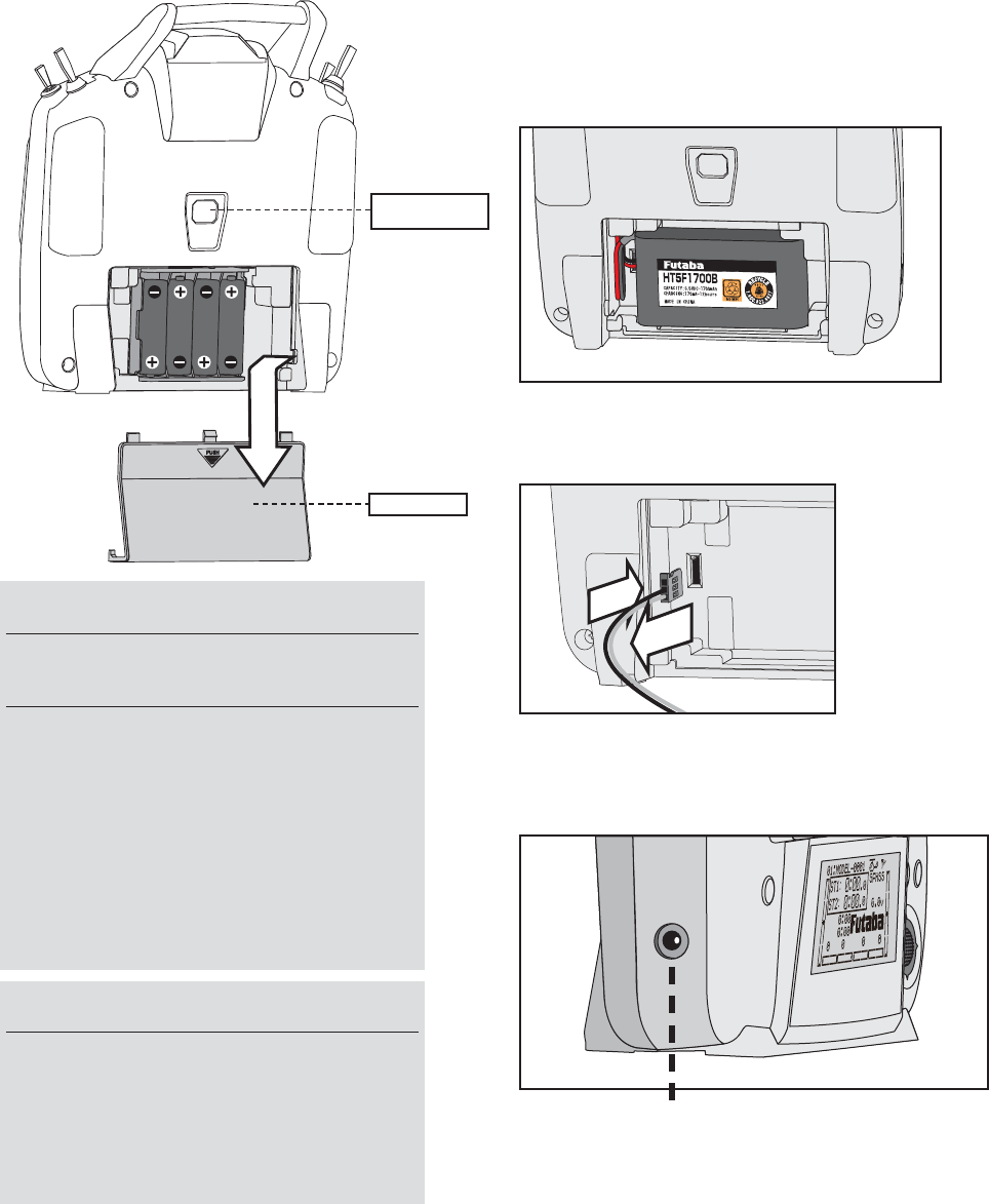
NOTE: If you need to remove or replace the
transmitter battery, do not pull strongly on the
battery wires to remove it. Insert the connector
straight as shown.
NOTE: This plug is for charging HT5F1700B.
The other battery cannot be charged.
FT2F2100B is removed from a transmitter, and
charges with an exclusive charger(LBC-4E5).
INSTALLATION AND REMOVAL OF THE TRANSMITTER BATTERY
The T8J transmitter is designed to work with either
four (4) AA alkaline dry cell batteries, or HT5F1700B/
FR2F2100B battery pack, both available separately.
The transmitter batteries used are a matter of personal
preference. AA Alkaline batteries are available at any
local hobby shop, grocery store, etc. A battery pack
will need to be purchased from a hobby shop.
Remove the battery BOX if you choose to use the
optional HT5F1700B/FR2F2100B battery pack,
which can be recharged from the transmitter.
WARNING
Do not connect any other chargers except
the special charger to this charging
connector.
*If you take out the Ni-MH battery HT5F1700B from the
transmitter, you can use the optional quick charger CR-
2000 corresponding to Ni-MH battery.
WARNING
Be careful not to drop the battery.
Never disconnect the battery connector
from the T8J transmitter after turning off
the power until the screen is completely
blank and the transmitter has shut down
completely.
* Internal devices such as memories may be damaged.
* If there is any problem, the message "Backup Error" will
be shown the next time when you turn on the power of
the transmitter. Do not use the transmitter as it is. Send it
to the Futaba Service Center.
Trainer function
connector
Battery cover
push and slide down
13
SWITCH ASSIGNMENT TABLE
7KH IDFWRU\ GHIDXOW IXQFWLRQV DFWLYDWHG E\ WKH VZLWFKHV DQG95IRUDQ - 0RGH WUDQVPLWWHU DUH VKRZQ
below.
0RVW-IXQFWLRQVPD\EHUHDVVLJQHGWRQRQGHIDXOWSRVLWLRQVTXLFNO\DQGHDVLO\
%DVLFFRQWURODVVLJQPHQWVRIFKDQQHOVDUHTXLFNO\DGMXVWDEOHLQAUX-CH.
1RWHWKDWPRVWIXQFWLRQVQHHGWREHDFWLYDWHGLQWKHSURJUDPPLQJWRRSHUDWH
- 0RGH -+ DQG - WUDQVPLWWHU IXQFWLRQV DUH VLPLODU EXW UHYHUVH FHUWDLQ VZLWFK FRPPDQGV$OZD\V
check that you have the desired switch assignment for each function during set up.
Switch/VR
A or H
Airplane (ACRO) Helicopter (HELI)
SWITCH A elevator dual rate elevator dual rate
SWITCH B rudder dual rate rudder dual rate
SWITCH C up = ELE-FLP on
center/down = IDLE-DOWN
down = AIRBRAKE on
governor
SWITCH D aileron dual rate aileron dual rate
SWITCH E or G* landing gear/ch 5 throttle hold/ch5
SWITCH F or H* snap roll/trainer trainer/THR-CUT
SWITCH G or E* none idle-up 1 and 2
SWITCH H or F* none idle-up3/gyro
VR ÀDSFK
ÀDSWULPLIFLAPERON on)
CH8
*On the 8JA Mode 2 transmitters, the TOP LEFT SWITCHES are spring-loaded and 2-position; on the 8JA Mode 1, 8JH, those
switches are on the right side. For consistency, the switch position’s designation remains the same (upper left is F, etc), but the
functions are moved to match the switch type.
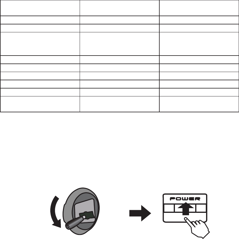
TO TURN ON THE 8J SYSTEM
First make sure the throttle stick is in the low throttle position.
Push up to turn on
*If the throttle stick is not in the low position,
you'll have an alarm until the stick is in the low position.
14
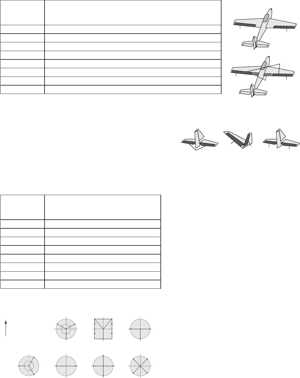
RECEIVER AND SERVO CONNECTIONS
Receiver
Output and
Channel
Aircraft (ACRO)
1 ailerons/aileron-11FRPELQHGÀDSDLOHURQ2
2 elevator
3 throttle
4 rudder
5 spare/landing gear/aileron-21,3FRPELQHGÀDSDQGDLOHURQ2,3
6VSDUHÀDSVFRPELQHGÀDSDQGDLOHURQ2
7 spare/aileron-21
8 spare/elevator-24/mixture control
1Aileron Differential mode (AILE-DIFF).
2Flaperon mode.
3Using Second Aileron option, second aileron servo output is sent to channels 5 and 6. ( AILE-2)
4AILEVATOR (dual elevator) mode.
Receiver
Output and
Channel
Helicopter (HELI)
1 aileron (cyclic roll)
2 elevator (cyclic pitch)
3 throttle
4 rudder
5 spare/gyro
6 pitch (collective pitch)
7 spare/governor
8 spare/mixture control
(Swash Type)
HR3H-1 H-3
ELE ELE
ELE1
ELE2
120˚
120˚120˚
PIT
(AIL)
AIL
(PIT)
PIT
(AIL)
AIL
(PIT)
HN3
120˚
120˚
120˚
ELE
PIT
AIL
HE3
ELE
PIT
(AIL)
AIL
(PIT)
PIT
(AIL)
AIL
(PIT)
H-2
PIT
FRONT
AIL
H-4
ELE1
ELE2 AIL
PIT
H4X
(Normal linkage type)
H-1:each servo linked
to the swashplate
independently.
(Wing Type)
(Tail Type)
AIL11
(CH1)
FLP
(CH6)
ACRO
(FLAP)
AIL21
(CH7)
ACRO
(FLAPERON)
AIL12
FLP22
(CH1)
AIL22
FLP12
(CH6)
AIL
(CH1)
(NORMAL)
ELE
(CH2)
(AILVATOR)
ELE1
AIL3
(CH2)
ELE2
AIL4
(CH8)
(V-TAIL)
ELE1
RUD2
(CH2)
ELE2
RUD1
(CH4)
15
According to the description of the battery to be used and its
exclusive charger, please use it after carrying out full charge.
We recommend charging the batteries with the charger
supplied with your system. Note that the use of a fast charger
may damage the batteries by overheating and dramatically
reduce their lifetime.
When HT5F1700B is chosen, HBC-3A (4) is recommended.
When charging FT2F2100B, Please make sure to remove the
battery from the system to charge it. Charger for this battery
is recommended to use LBC-4E5.
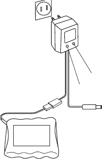
CHARGING THE BATTERIES (When the rechargeable battery option is used)
Charging Your System’s Batteries
1. Connect the transmitter charging jack and batteries to the transmitter and receiver connectors of the
charger.
2. Plug the charger into a wall socket.
3. Check that the charger LED lights.
Charger
TX: Transmitter charging indicator
RX: Receiver charging indicator
To transmitter charging jack
Receiver battery
Battery Care and Precautions
%HORZ\RXZLOO¿QGVRPHJHQHUDOUXOHVDQGJXLGHOLQHVZKLFKVKRXOGEHDGKHUHGWRZKHQFKDUJLQJWUDQVPLWWHU
and/or receiver battery packs. These are included to serve only as general guidelines, and are not intended
to replace or supersede the information provided by the battery and/or charger manufacturer. For complete
information, please refer to the instructions that are included with the battery pack(s) and/or chargers that
accompany the products purchased.
Do not allow children to charge battery packs without adult supervision.
Do not charge battery packs that have been damaged in any way. We strongly suggest frequent inspection
of the battery packs to ensure that no damage has occurred.
Do not to allow batteries to overheat! If overheated, disconnect the battery from the charger immediately
and allow to cool.
'RQRWPL[FHOOVDOOFHOOVVKRXOGEHRIWKHVDPHPDWHULDOFRQ¿JXUDWLRQHWF
Do not deep cycle NiMH batteries as permanent damage could result.
Never charge batteries on a surface that may become hot, or may be impacted by the heat.
Immediately end the charging procedure if either the batteries or charger itself become overly hot.
NiMH cells do not exhibit the “memory effect” like NiCd cells, so little cycling is needed. Store NiMH
packs with some voltage remaining on the cells (refer to battery supplier).
NiMH cells have a self-discharge rate of approximately 20-25% (compared to 15% for NiCd batteries). It is
important to recharge NiMH batteries immediately prior to use.
Never connect the battery in reverse. Reverse connection will cause the battery to overheat or will damage
the inside of the charger.
Do not add an additional charge after charging.
Never charge with a current exceeding the nominal capacity (lC) of the rechargeable battery.
If a battery is charged with a current exceeding 1C, the battery will overheat and deteriorate.
Do not connect two battery packs or more to one output terminal.
Avoid extremely cold and hot places and the direct sunlight when you charge batteries.
It is recommended to perform charging within the 10 ~ 30°C (50-85°F) range. Otherwise, it may cause
abnormal charging and overheat.
16
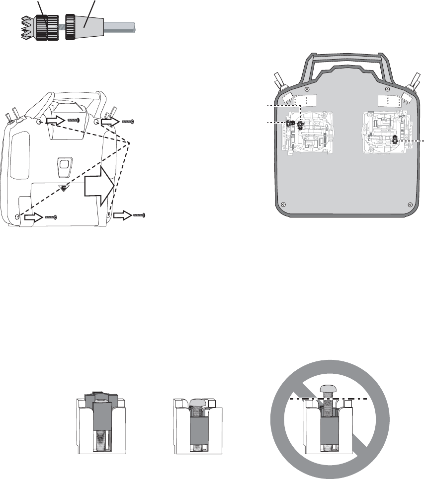
ADJUSTING THE IENGTH OF THE CONTROL STICKS
<RXPD\DGMXVWWKHWHQVLRQRI\RXUVWLFNVWRSURYLGHWKHIHHOWKDW \RXSUHIHU IRUIO\LQJ7RDGMXVW\RXU
springs, you’ll have to remove the rear case of the transmitter. First, remove the battery cover on the rear
of the transmitter. Next, unplug the battery wire, and remove the battery from the transmitter. Next, using a
screwdriver, remove the four screws that hold the transmitter’s rear cover in position, and put them in a safe
SODFH*HQWO\HDVHRIIWKHWUDQVPLWWHU¶VUHDUFRYHU1RZ\RX¶OOVHHWKHYLHZVKRZQLQWKH¿JXUHDERYH
Using a small Phillips screwdriver, rotate the adjusting screw for each stick for the desired spring tension.
The tension increases when the adjusting screw is turned clockwise. When you are satisfied with the
spring tensions, reattach the transmitter's rear cover. When the cover is properly in place, reinstall and tighten
the four screws. Reinstall the battery and cover.
<RXPD\FKDQJHWKHOHQJWKRIWKHFRQWUROVWLFNVWRPDNH\RXU
transmitter more comfortable to hold and operate. To lengthen or
VKRUWHQ \RXU WUDQVPLWWHU¶V VWLFNV ¿UVW XQORFN WKH VWLFN WLS E\ KROGLQJ
locking piece B and turning stick tip A counterclockwise. Next, move
the locking piece B up or down (to lengthen or shorten). When the
length feels comfortable, lock the position by turning locking piece B
counterclockwise.
Stick tip A Locking piece B
Stick lever tension adjustment
Mode 2 transmitter with rear case removed.
Aileron
Elevator
Rudder
StickStick
Four screws are
removed and rear
case is removed.
ADJUSTING DISPLAY CONTRAST
To adjust the display contrast, from the home menu press and hold the END BUTTON.
Push the +− KEY while still holding the END BUTTON:
+KEY to brighten
−KEY to darken the display
+ screw is clockwise.
Stick tension maximum Stick tension minimum
+ screw is counter-clockwise.
A screw is kept
from coming out
from a line.
※A screw touches a case.

17
RANGE CHECK THE RADIO
$UDQJHFKHFNPXVWEHSHUIRUPHGEHIRUHWKH¿UVWÀLJKWRIDQHZPRGHO,WLVQRWQHFHVVDU\WRGRDUDQJH
FKHFNEHIRUHHYHU\ÀLJKWEXWLVQRWDEDGLGHDWRSHUIRUPDUDQJHFKHFNEHIRUHWKH¿UVWÀLJKWRIHDFKGD\
$ UDQJH FKHFN LV WKH ¿QDO RSSRUWXQLW\ WR UHYHDO DQ\ UDGLR PDOIXQFWLRQV DQG WR EH FHUWDLQ WKH V\VWHP KDV
adequate operational range.
We have installed a special “Power Down Mode” in the T8J in order to perform an operational ground range
check. During this mode, the RF power is reduced in order to test the operational range of the T8J.
To activate the Power Down Mode and Perform A Range Check:
1) To activate the “Power Down Mode” please hold down the JOG KEY and then turn the transmitter switch
on. A power mode screen comes out. JOG KEY is pushed where Power Down is chosen. When this mode is
active the Purple LED on the Lighting front of the transmitter will provide users with an audible and visual
indication that the transmitter is in the “Power Down Mode”.
Audibly, the transmitter will beep one time every three seconds. Visually, the LCD screen will display
“POWER DOWN MODE”. The words “POWER DOWN MODE” will blink as an additional reminder that
the transmitter is in the “Power Down Mode”.
2) With the “Power Down Mode” activated, walk away from the model while simultaneously operating the
FRQWUROV+DYHDQDVVLVWDQWVWDQGE\WKHPRGHODQGVLJQDOZKDWWKHFRQWUROVDUHGRLQJWRFRQ¿UPWKDWWKH\
RSHUDWHFRUUHFWO\<RXVKRXOG EHDEOHWRZDONDSSUR[LPDWHO\SDFHVIURPWKHPRGHOZLWKRXW ORVLQJ
control.
3) If everything operates correctly, return to the model. Push END KEY and complete power down mode.
Set the transmitter in a safe yet accessible location so it will be within reach after starting the engine. Be
certain the throttle stick is all the way down, and then start the engine. Perform another range check with
your assistant holding the model and the engine running at various speeds.
,IWKHVHUYRVMLWWHURUPRYHLQDGYHUWHQWO\WKHUHPD\EHDSUREOHP'R127À\WKHDLUFUDIW/RRNIRUORRVH
servo connections or binding pushrods. Also be certain that the battery has been fully charged.
1(9(5VWDUWÀ\LQJZKHQWKH³3RZHU'RZQ0RGH´LVDFWLYH
Servo test operation at the time of Power Down Mode:
'XULQJ3RZHU'RZQPRGH\RXFDQXVHDXWRPDWLFVHUYRWHVWLQJWRFKHFNWKHUDQJHRIDVSHFL¿HGVHUYRLW
moves to right and left slowly).
1) A "servo test" is chosen from a menu.
2) JOG KEY is moved to a side and 2 pages is called. Next, JOG KEY is moved down and CH is displayed.
3) CH of the servo which wants to operate is chosen. Then, the + KEY is pressed and it is made ACT.
The servo selected during Power Down mode operates alone, allowing you to check its operation.
*In the power down mode, the throttle servo does not operate. (Slow keeping)
+HOLFRSWHUPRGHFRQGLWLRQLV¿[HGWR125
DANGER
NEVER start flying when the “Power
Down Mode” is active.
*Control is impossible and your model crashes.
18
RADIO INSTALLATION
Follow these guidelines to properly mount the servos, receiver and battery.
0DNHFHUWDLQWKHalignment tab on the battery, switch and servo connectors is oriented correctly and “keys”
into the corresponding notch in the receiver or connectors before plugging them in. When unplugging
connectors, never pull on the wires. Always pull on the plastic connector instead.
,I\RXUDLOHURQVHUYRRURWKHUVDUHWRRIDUDZD\WRSOXJLQWRWKHUHFHLYHUXVHDQDLOHURQH[WHQVLRQFRUG
to extend the length of the servo lead. Additional Futaba extension cords of varying lengths are available
from your hobby dealer. Always use an extension of the proper length. Avoid plugging multiple extensions
together to attain your desired length. If distance is greater than 18” or multiple or high current draw servos
are being used, use Futaba Heavy-Duty servo extensions.
Servo Rubber
grommet Servo Rubber
grommet
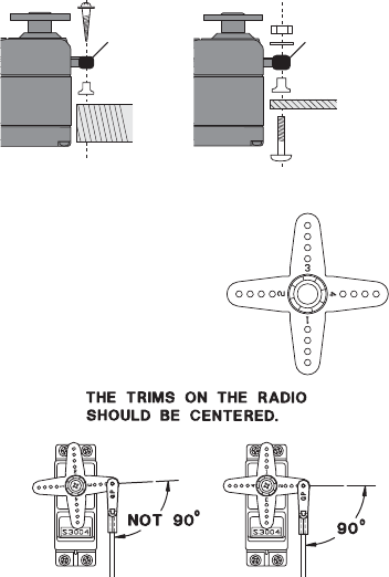
$OZD\V PRXQW WKH VHUYRV ZLWK WKH VXSSOLHG rubber grommets.
Do not over tighten the screws. No part of the servo casing
should contact the mounting rails, servo tray or any other part
of the airplane/helicopter structure. Otherwise, vibration will be
transmitted to the servo, causing premature wear and/or servo
failure.
1RWHWKHVPDOOQXPEHUVPROGHGLQWRHDFKDUPRQWKH)XWDEDDUPVHUYRDUPV
The numbers indicate how many degrees each arm is “off” from 90 degrees to correct for
minute manufacturing deviations from servo to servo.
7R FHQWHU WKH VHUYRV FRQQHFW WKHP WR WKH UHFHLYHU DQG WXUQ RQ WKH
WUDQVPLWWHUDQGUHFHLYHU&HQWHUWKHWULPVRQWKHWUDQVPLWWHUWKHQ¿QG
the arm that will be perpendicular to the pushrod when placed on the
servo.
$IWHUWKHVHUYRVDUHLQVWDOOHGRSHUDWHHDFKVHUYRRYHULWVIXOOWUDYHODQGFKHFNWKDWWKHSXVKURGVDQGVHUYR
arms do not bind or contact each other. Also make sure the controls do not require excess force to operate.
If there is an objectionable buzzing sound coming from a servo, there is probably too much resistance in the
control. Find and correct the problem. Even if there is no servo damage, excess battery drain will result.
8VHWKHmounting plate from the receiver on/off switch as a template for the cutout and screw holes. Mount
the switch on the side of the fuselage opposite the engine exhaust, and where it won’t be inadvertently
turned on or off during handling or storage. Be certain the switch moves without restriction and “snaps”
from ON to OFF, and that the cutout allows full motion of the switch in both directions.
:KHQ\RXLQVWDOOWKHVZLWFKKDUQHVVWRWKHKHOLFRSWHUSOHDVHXVHWKHVZLWFKFRYHU*HQHUDOO\VDQGZLFKWKH
frame between the switch and switch cover and securely tighten the screws. Different models might require
different installations. If so, please follow the model's instruction manual.
19
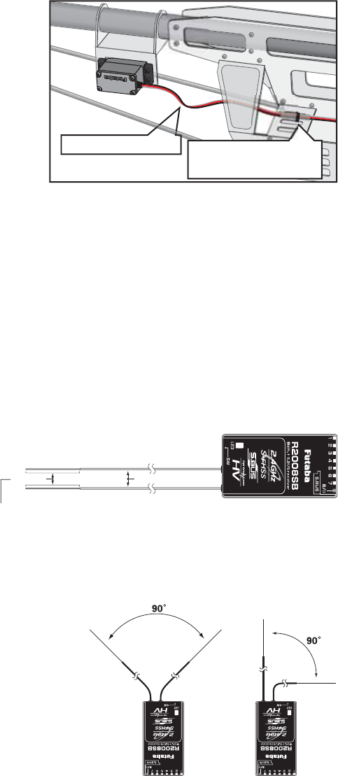
7RSUHYHQWWKHVHUYROHDGZLUHVIURPEHLQJEURNHQE\
vibration during flight, provide a slight amount of slack
or extra so that the wire sticks out slightly and fasten it at
suitable points. In addition, periodically check the wire
during daily maintenance.
IMPORTANT: Since the 2.4GHz have different characteristics than that of the conventional 27MHz and
72MHz frequencies, please read this section carefully to maximize your enjoyment of the 2.4GHz system.
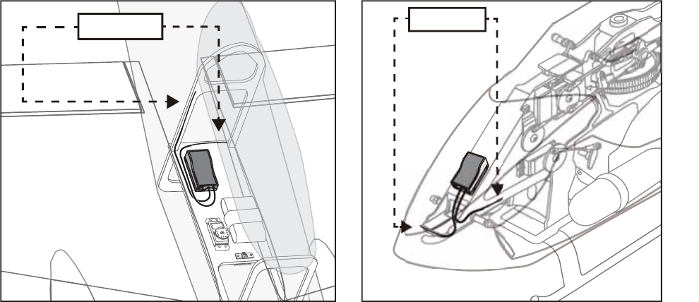
Receiver's Antenna Installation:
Antenna
*Must be kept as straight as possible.
Coaxial cable
R2008SB Receiver
<RXZLOOQRWHWKDWWKH56%GLIIHUVLQ
appearance from the standard Futaba receiver.
These receivers incorporate two separate antennas
into their design which enables them to receive
the radio frequency transmission at two different
locations.
Futaba's dual antenna diversity then seamlessly selects the best signal reception between these antennas to
ensure that there is no loss of signal.
7RREWDLQWKHEHVWUHVXOWVRIWKHGLYHUVLW\IXQFWLRQSOHDVHUHIHUWRWKHIROORZLQJLQVWUXFWLRQV
1. The two antennas must be kept as straight as possible. Otherwise
it will reduce the effective range.
2. The two antennas should be placed at 90 degrees to each other.
7KLVLVQRWDFULWLFDO¿JXUHEXWWKHPRVWLPSRUWDQWWKLQJLVWRNHHS
the antennas away from each other as much as possible.
Larger models can have large metal objects that can attenuate the
RF signal. In this case the antennas should be placed at both sides
of the model. Then the best RF signal condition is obtained at any
À\LQJDWWLWXGH
3. The antennas must be kept away from conductive materials, such as metal, carbon and fuel tank by at least
a half inch. The coaxial part of the antennas does not need to follow these guidelines, but do not bend it in a
tight radius.
4. Keep the antennas away from the motor, ESC, and other noise sources as much as possible.
Fasten about 5-10cm
from the servo outlet so
that the lead wire is neat.
Margin in the lead wire.
20
5HFHLYHU9LEUDWLRQDQG:DWHUSURR¿QJ7KHUHFHLYHUFRQWDLQV SUHFLVLRQ HOHFWURQLF SDUWV %H VXUH WR DYRLG
vibration, shock, and temperature extremes. For protection, wrap the receiver in foam rubber or other
vibration-absorbing materials. It is also a good idea to waterproof the receiver by placing it in a plastic
bag and securing the open end of the bag with a rubber band before wrapping it with foam rubber. If you
accidentally get moisture or fuel inside the receiver, you may experience intermittent operation or a crash. If
in doubt, return the receiver to our service center for service.
*The two antennas should be placed at 90 degrees to each other.
*The main purpose of the photo demonstrates how the antenna should be placed.
Antenna Antenna

21
LED Indication
Green Red Status
Off Solid No signal reception
Solid Off Receiving signals
Blink Off Receiving signals but ID is unmatched
Alternate blink Unrecoverable error (Memory, etc.)
Please refer the table below for LED status vs
receiver's condition.
LINK PROCEDURE (T8J transmitter/R2008SB):
Each transmitter has an individually assigned, unique ID code. In order to start operation, the receiver must
be linked with the ID code of the transmitter with which it is being paired. Once the link is made, the ID
code is stored in the receiver and no further linking is necessary unless the receiver is to be used with another
transmitter. When you purchase additional R2008SB receivers, this procedure is necessary; otherwise the
receiver will not work.
1. Bring the transmitter and the receiver close to each other, within 20 inches (half meter).
2. Turn on the transmitter.
3. Turn on the receiver.
4. Press and hold the Link switch more than two (2) seconds. When the link is complete, the LED in the
receiver changes to solid green. When the ID cannot be read due to the surrounding environment, try
reading it with the transmitter and receiver touched.
,IWKHUHDUHPDQ\6)+66)+66V\VWHPVWXUQHGRQLQFORVHSUR[LPLW\\RXUUHFHLYHUPLJKWQRWOLQNWR\RXU
transmitter. In this case, even if the receiver's LED stays solid green, unfortunately the receiver might have
established a link to one of other transmitters. This is very dangerous if you do not notice this situation. In
order to avoid the problem, we strongly recommend you to doublecheck whether your receiver is really
under control by your transmitter by giving the stick input and then checking the servo response.
WARNING
After the linking is done, please cycle receiver power and check if the receiver to be linked is really
under the control by the transmitter to be linked.
Do not perform the linking procedure with motor's main wire connected or with the engine operating as
it may result in serious injury.
22
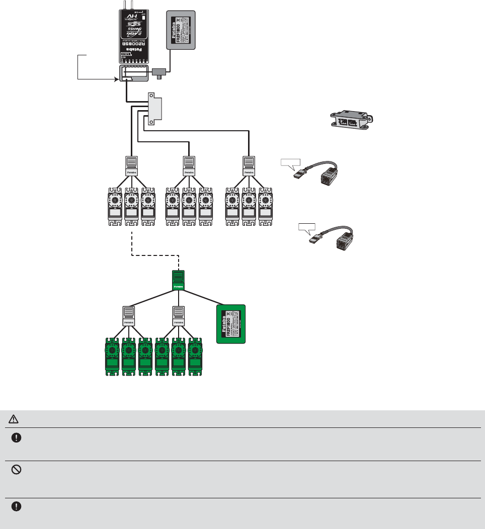
S.BUS INSTALLATION
This set uses the S.BUS system. The wiring is as simplified and clean mounting as possible, even with
models that use a large number of servos. In addition, the wings can be quickly installed to the fuselage
without any erroneous wiring by the use of only one simple wire, even when there are a large number of
servos used.
Ɣ:KHQXVLQJ6%86VSHFLDOVHWWLQJVDQGPL[HVLQ\RXUWUDQVPLWWHUPD\EHXQQHFHVVDU\
Ɣ7KH6%86VHUYRVDQG6%86J\URVPHPRUL]HWKHQXPEHURIFKDQQHOVWKHPVHOYHV6HWWDEOHZLWKWKH6%&
Ɣ7KH6%86V\VWHPDQGFRQYHQWLRQDOV\VWHPUHFHLYHUFRQYHQWLRQDO&+XVHGFDQEHPL[HG
Battery
Battery
Male to Male
connectors.
Switch
Terminal box
HUB
HUB HUB
HUB HUB
●HUB
HUB
ق$QRWKHUSRZHUVXSSO\ك
●HUB
ق$QRWKHUSRZHUVXSSO\ك
S.BUS Servo
S.BUS Servo
Receiver
●S.BUS Servo
Since the channel number is memorized by
the S.BUS itself, any connector can be used.
When the SBD-1 (sold separately) is used,
ordinary servos can be used with the
S.BUS system.
●When separate power supply used
When a large number of servos is used or
when high current servos are used, the servos
can be driven by a separate power supply by
using a separate Power Supply 3-way Hub.
●Terminal box
Four connectors can be inserted
Three connectors can be
inserted.
Used when using a separate
power supply battery.
S.BUS
Port
(S.BUS)
Orange
Green
WARNING
7XUQRQWKHSRZHURQWUDQVPLWWHUĺUHFHLYHULQRUGHU,QDGGLWLRQDOZD\VFKHFNWKHRSHUDWLRQRIDOOWKH
VHUYRVEHIRUHÀLJKW
Do not insert or remove the servo connector while the receiver power is ON.
Since the S.BUS servo switches the operation mode automatically according to the type of signal (S.BUS signal/PWM signal) from the receiver, if the
connector is inserted or removed while the power is ON, an S.BUS connected servo will be erroneously recognized and may stop.
Please make sure that you use a battery that can deliver enough capacity for the number and kind of
servos used. Alkaline batteries cannot be used.
23
TRANSMITTER DISPLAYS & BUTTONS
:KHQ \RX ¿UVW WXUQ RQ \RXU WUDQVPLWWHU D FRQ¿UPDWLRQ GRXEOH EHHS VRXQGV DQG WKH VFUHHQ VKRZQ EHORZ
DSSHDUV%HIRUHÀ\LQJRUHYHQVWDUWLQJWKHHQJLQHEHVXUHWKDWWKHPRGHOW\SHDQGQDPHDSSHDULQJRQWKH
GLVSOD\PDWFKHVWKHPRGHOWKDW\RXDUHDERXWWRÀ\,I\RXDUHLQWKHZURQJPRGHOPHPRU\VHUYRVPD\EH
reversed, and travels and trims will be wrong, potentially leading to a crash.
(GLWEXWWRQVDQG6WDUWXS6FUHHQDSSHDUVZKHQV\VWHPLV¿UVWWXUQHGRQ
JOG KEY:
Control JOG KEY to scroll up/scroll down/scroll left/scroll right and select the option to edit within a
function. When the menu has multiple pages, move the JOG KEY horizontally (left or right).
Press JOG KEY to select the actual function you wish to edit from the menu.
Press JOG KEY and hold one second to confirm major decisions, such as the decision to: select a
different model from memory, copy one model memory over another, trim reset, store channel position
in FailSafe, change model type, reset entire model, condition of a helicopter setup is changed. An on
screen inquiry will ask if you are sure.
Press JOG KEY again to accept the change.
+ KEY:
Press and hold + KEY for one second to open programming menus. It uses for change of a setup, or a
numerical increase. Change of the page of a menu can also be performed.
−KEY:
It is used for change of a setup, or reduction of a number. Change of the page of a menu can also be
performed.
END BUTTON:
Press END BUTTON to return to previous screen. Closes functions back to menus, closes menus to
start-up screen.
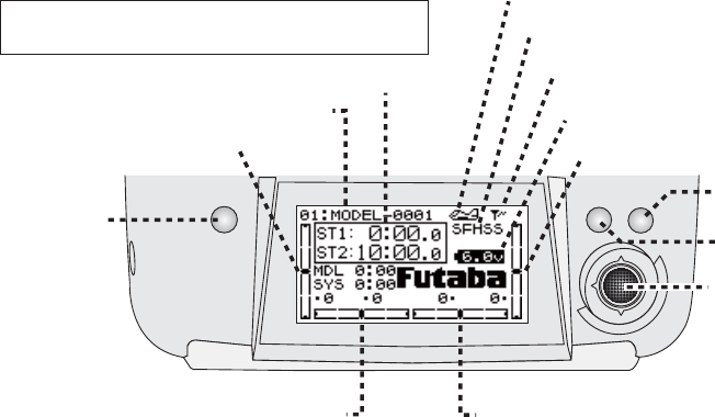
Rudder trim
display Aileron trim
display
Timers
Throttle trim
display
Model number
and name
Jog key
END
Key
Total timer display <TIMER>
Shows the cumulated ON time. (hours:minutes)
Up/down timer display <ST1.ST2>
(minutes:seconds)
Model timer display <MDL>
Shows the cumulated ON time for each model.(hours:minutes)
System timer display <SYS>
Shows the cumulated ON time.(hours:minutes)
Resetting timers:
Select the desired timer with JOG KEY. The timer display
flashes. To reset the timer, press JOG KEY.
Elevator trim
display
Battery
voltage
System
ࠉ"S-FHSS" "FHSS"
Model type
Output display
−key
+key
24
WARNING & ERROR DISPLAYS
An alarm or error indication may appear on the display of your transmitter for a number of reasons, including
when the transmitter power switch is turned on, when the battery voltage is low, and several others. Each
display has a unique sound associated with it, as described below.
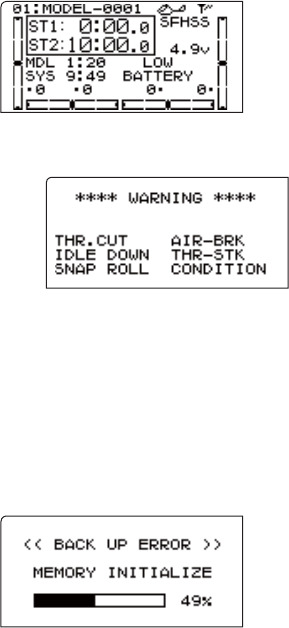
LOW BATTERY ERROR: Warning sound: Continuous beep until transmitter is powered off.
The LOW BATTERY warning is displayed when the transmitter battery voltage drops below 4.1V. (5CELL mode
4.9V)
Land your model as soon as possible before loss of control due to a dead
battery.
MIXING ALERT WARNING: Warning sound: 5 Beeps (repeated until problem resolved or overridden)
The MIXING ALERT warning is displayed to alert you whenever you turn on
the transmitter with any of the mixing switches active. This warning will
disappear when the offending switch or control is deactivated. Switches for
which warnings will be issued at power-up are listed below. Throttle cut,
idle-down, snap roll, airbrake, throttle-stick and condition. If turning a switch OFF does not stop the
mixing warning: When the warning does not stop even when the mixing switch indicated by the
warning display on the screen is turned off, the functions described previously probably use the same
switch and the OFF direction setting is reversed. In short, one of the mixings described above is not in
the OFF state. In this case, reset the warning display by pressing both +/−KEY at the same time.
Next, change one of the switch settings of the duplicated mixings.
BACKUP ERROR: Warning sound: 4 beeps (repeated continuously)
The BACKUP ERROR warning occurs when the transmitter memory is lost for any reason. If this occurs, all of
the data will be reset when the power is turned on again.
'RQRWÀ\ZKHQ WKLVPHVVDJHLVGLVSOD\HG: all programming has been erased
and is not available. Return your transmitter to Futaba for service.
25
AIRCRAFT (ACRO) MENU FUNCTIONS
Model Select .....................................................27
Model Copy ......................................................27
Model Data Reset...............................................28
Model Name ......................................................29
Parameter ...........................................................30
Model Type ........................................................30
RX select (S-FHSS /FHSS) ...............................31
ATL ....................................................................32
LED adjustment .................................................32
Battery Type.......................................................33
Model Date Transmission .................................34
Reverse ..............................................................35
End Point ..........................................................36
Idle Down ..........................................................37
Throttle Cut........................................................38
D/R, EXP ...........................................................39
Timer..................................................................42
AUX CH ............................................................43
Trainer................................................................44
Trim....................................................................45
Sub Trim ............................................................46
Servo ..................................................................47
Fail Safe .............................................................48
Flaperon (ACRO Only) .....................................50
Flap Trim (ACRO Only)....................................51
AIL DIFF (ACRO Only) ...................................52
Elevon (ACRO Only) ........................................53
Ailevator (ACRO Only) ....................................54
V-Tail (ACRO Only)..........................................55
Snap-Roll (ACRO Only) ...................................56
ELE-FLAP (ACRO Only) .................................59
Airbrake (ACRO Only) .....................................61
THR →Needle .................................................62
THR Delay (ACRO Only) .................................63
THR-Curve (ACRO Only) ................................64
PIT-Curve (ACRO Only)...................................64
Programmable MIX ...........................................65
*<526(16$&522QO\ .............................64
26
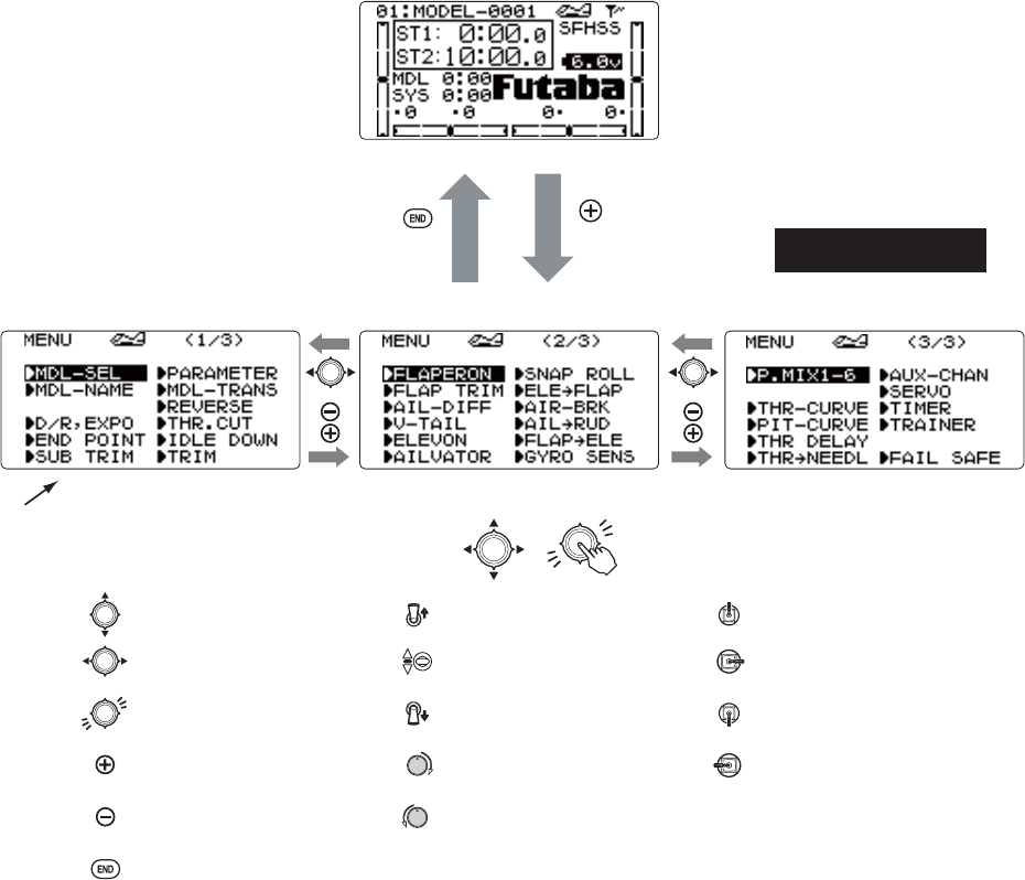
ACRO Menu
( for one second)
or
(Startup screen)
(Menu 1/3) (Menu 2/3) (Menu 3/3)
To enter the Menu,
press the +key for one second.
Press 㸩㸫Key to page up and down through the 3 pages of screens
in each menu. Note that all functions which have more than one page have
a <1/3> indicator in the upper right hand corner to indicate page 1 of 3 or
page 2 of 3 / 3 of 3.
Use Jog Key to highlight function in Menu screen.
Then press the Dial to choose that function.
Jog Key Up/Down
Jog Key Left/Right
Press Jog Key
Press + Key
Press − Key
End Selection
Switch Up
Switch at Center
Switch Down
Stick Up
Stick Right
Stick Down
Stick Left
Turn VR Right
Turn VR Left
or
MAP OF ACRO FUNCTIONS
To return to the Startup screen,
press the End key.
27
A LOOK AT THE RADIO'S FUNCTIONS STEP BY STEP
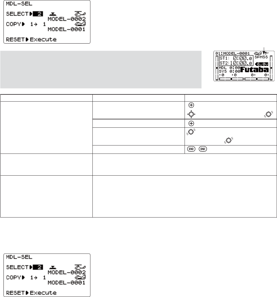
MODEL SELECT submenu: includes three functions that manage model memory: MODEL SELECT,MODEL COPY and MODEL
RESET. Since these functions are all related, and are all basic features used with most models, they are together in the
MODEL SELECT submenu.
NOTE: When you choose a new model in the MODEL SELECT function, if the new
model is set to a different modulation, you must cycle the transmitter power to change
PRGXODWLRQV,I\RXGRQRWF\FOHWKHSRZHUWKHPRGXODWLRQW\SHZLOOÀDVKRQWKHKRPH
screen to remind you. Please note: You are still transmitting on the other modulation
until you affect this change.
GOAL: STEPS: INPUTS:
Select Model #3.
NOTE: This is one of several
functions for which the radio requires
FRQ¿UPDWLRQWRPDNHDFKDQJH
Open the menu, then open MODEL
SELECT submenu.
for 1 second.
if required to MODEL SELECT.
Choose Model #3. to 3.
&RQ¿UP\RXUFKDQJH for 1 second.
Sure? displays.
Close.
Confirm proper modulation of new
model memory.
If SFHSS/FHSS LV ÀDVKLQJ LQ WKH XSSHU ULJKW KDQG FRUQHU WKHQ WKH QHZ PRGHO
is set for the other receiver type. Turn the transmitter off/on to change the
modulation.
Where next? MODEL NAME the model: see p. 29.
Change MODEL TYPE (aircraft, heli): see p. 30.
Change modulation (SFHSS or FHSS): see p. 31.
Utilize servo REVERSE: see p. 35.
Adjust END POINTs: see p. 36.
Set up IDLE-DOWN and THR-CUT for throttle management: see p. 37, 38.
MODEL SELECT: This function selects which of the 20 model memories in the
WUDQVPLWWHUWRVHWXSRUÀ\)RUFODULW\WKHPRGHOVQDPHDQGDQLPDJHRILWVW\SH
are indicated after its number. (Each model memory may be a different model
type from the other memories.)
MODEL COPY: copies the current model data into another model memory in the transmitter. The name of the model memory
you are copying into is displayed for clarity.
Notes:
$Q\GDWDLQWKHPRGHOFRSLHGWRZLOOEHZULWWHQRYHUDQGORVWLQFOXGLQJQDPH
type and modulation. Upon completion, it cannot be recovered.
ÀDVKLQJ
Examples:
&UHDWHDQHZPRGHOWKDWLVVLPLODUWRRQH\RXKDYHDOUHDG\SURJUDPPHG
&RS\WKHFXUUHQWPRGHOGDWDLQWRDQRWKHUPRGHOPHPRU\DVDEDFNXSRUEHIRUHH[SHULPHQWLQJZLWKQHZVHWWLQJV
(GLW D FRS\ RI \RXU PRGHO¶V GDWD WR À\ WKH PRGHO LQ GLIIHUHQW FRQGLWLRQV LH +HOLFRSWHU XVLQJ KHDYLHU ZHLJKW EODGHV
airplane model at extreme altitudes).
28
GOAL of EXAMPLE: STEPS: INPUTS:
Copy model 3 into model 5.
NOTE: This is one of several
functions for which the radio requires
FRQ¿UPDWLRQWRPDNHDFKDQJH
Open the menu, then open MODEL
SELECT submenu.
for 1 second.
if required to MODEL SELECT.
Confirm you are currently using the
proper model memory. (Ex: 3)
If SELECT does not indicate 3, use MODEL
SELECT, p. 27.
Go to MODEL COPY and choose the
model to copy into. (Ex: 5)
to COPY. to 5.
&RQ¿UP\RXUFKDQJH for 1 second.
Sure? displays. *
Close.
Where next? SELECT the copy you just made: see p. 27.
Rename it (it is currently named exactly the same as the model copied): see p. 29.
*Radio will show "complete" and it shows that the copy was completed. Note that if the power switch is turned off prior to completion, the data will
not be copied.
)LUVWLWLVLPSRUWDQWWRFOHDURXWDQ\ROGVHWWLQJVLQWKHPHPRU\IURPSULRUXVHXVLQJWKHMODEL RESET.
MODEL RESETFRPSOHWHO\UHVHWVDOOGDWDLQWKHLQGLYLGXDOPRGHO\RXKDYHFXUUHQWO\VHOHFWHG'RQWZRUU\WKHUHLVQRZD\
you can accidentally delete all models in your radio with this function. Only a service center can completely reset your
UDGLRVHQWLUHPHPRU\DWRQFH7RGHOHWHHDFKPRGHOLQ\RXUUDGLRVPHPRU\IRUH[DPSOHZKHQVHOOLQJ\RXPXVWSELECT
each model, reset that memory, then go SELECT the next memory, etc.
Note that when you COPYRQHPRGHOPHPRU\LQWRDQRWKHURUFKDQJHWKHPRGHOVW\SH\RXQHHGQRWGHOHWHDOOH[LVWLQJGDWD
¿UVWE\XVLQJWKLVIXQFWLRQCOPY completely overwrites anything in the existing model memory, including MODEL NAME.
The MODEL TYPE function overwrites all data except name and RX MODUL.
GOAL of EXAMPLE: STEPS: INPUTS:
Reset model memory 1.
NOTE: This is one of several
functions for which the radio requires
FRQ¿UPDWLRQWRPDNHDFKDQJH
Confirm you are currently using the
proper model memory. (Ex: 1)
2QKRPHVFUHHQFKHFNPRGHOQDPHDQG
number on top left. If it is not correct,
use MODEL SELECT.
Open the menu, then open MODEL
SELECT submenu.
for 1 second.
if required to MODEL SELECT.
Go to MODEL RESET and reset the
memory.
to RESET. for 1 second.
&RQ¿UPWKHFKDQJH Sure? displays. *
Close.
Where next? Now that the memory is reset, name has returned to the default (Ex:
MODEL-0001).
NAME the model: p. 29.
COPY a different model into this memory: p. 27.
SELECT a different model to edit or delete: p. 27.
Change the MODEL TYPE to airplane or helicopter: see p. 30.
Change the receiver modulation [SFHSS or FHSS]: see p. 31.
Utilize servo REVERSE: see p. 35.
Adjust servo travel with END POINT: see p. 36.
Set up dual/triple rates and exponential (D/R,EXP): see p. 39.
*Radio will show a "complete" and it shows that the reset was completed. Note that if the power switch is turned off prior to completion, the data will
not be reset.
29
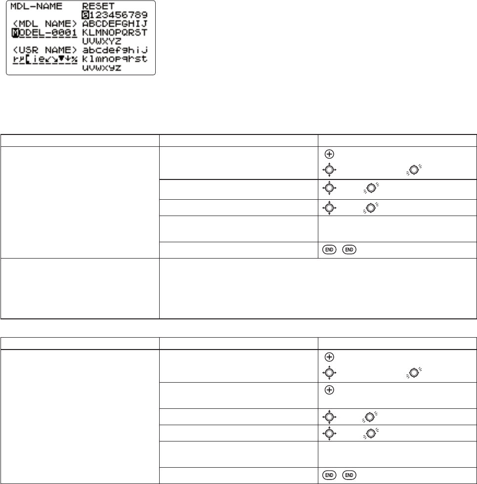
MODEL NAME/USER NAME:
MODEL NAME assigns a name to the current model memory. By giving each model a name that is immediately recognizable,
\RXFDQTXLFNO\VHOHFWWKHFRUUHFWPRGHODQGPLQLPL]HWKHFKDQFHRIÀ\LQJWKHZURQJPRGHOPHPRU\ZKLFKFRXOGOHDGWR
a crash.
USER NAMEDVVLJQV\RXUWUDQVPLWWHUVQDPHZKLFKLVGLVSOD\HGLQWKHKRPHVFUHHQ
Adjustability and values:
8SWRFKDUDFWHUVORQJ
(DFKFKDUDFWHUPD\EHDOHWWHUQXPEHUEODQNRUDV\PERO
MODEL NAME: 7KHGHIDXOWQDPHVDVVLJQHGE\WKHIDFWRU\DUHLQ02'(/[[[[
format (MODEL-0001 IRU¿UVWPRGHOPHPRU\HWF
USER NAME: 7KHGHIDXOWQDPHDVVLJQHGE\WKHIDFWRU\LVWKH)XWDEDORJR
NOTE: When you COPY one model memory over another, everythingLVFRSLHGLQFOXGLQJWKHPRGHOVQDPH6LPLODUO\LI
you change MODEL TYPE or do a MODEL RESET, the entire memory is reset, including MODEL NAME6RWKH¿UVWWKLQJ\RXZLOO
want to do after you COPY a model, change its type, or start from scratch, is rename the new copy to avoid confusion.
GOAL of EXAMPLE: STEPS: INPUTS:
1DPH PRGHO ³&DSB´ ZKHUH WKH
XQGHUOLQHUHSUHVHQWVDEODQNVSDFH
Open MODEL NAME submenu. for 1 second.
to MODEL NAME.
&KDQJHWKH¿UVWFKDUDFWHU([0WR& to C.
Change the next character. (Ex: O to a) to a.(note: lower case is available)
Repeat the prior steps to complete
naming the model.
Repeat.
Close.
Where next? Change the MODEL TYPE to airplane or helicopter: see p. 30.
Change modulation [SFHSS or FHSS]: see p. 31.
Utilize servo REVERSE: see p. 35.
Adjust servo travel with END POINT: see p. 36.
Set up dual/triple rates and exponential (D/R,EXP): see p. 39.
GOAL of EXAMPLE: STEPS: INPUTS:
Name USER NAME³)XWDED´ Open MODEL NAME submenu. for 1 second.
to MODEL NAME.
Go to USER NAME and select the first
FKDUDFWHU([WR)
WRWKH¿UVWFKDUDFWHURIUSER NAME.
&KDQJHWKH¿UVWFKDUDFWHU([BWR) to F.
&KDQJHWKHQH[WFKDUDFWHU([BWRX to u.(note: lower case is available)
Repeat the prior steps to complete
naming the system.
Repeat.
Close.
8VHUQDPHLVQRWVKRZQRQWKHKRPHPDLQVFUHHQ%XWFDQEHGRQHE\VHWWLQJXQGHUWKH3DUDPHWHU)XQFWLRQRQS
30
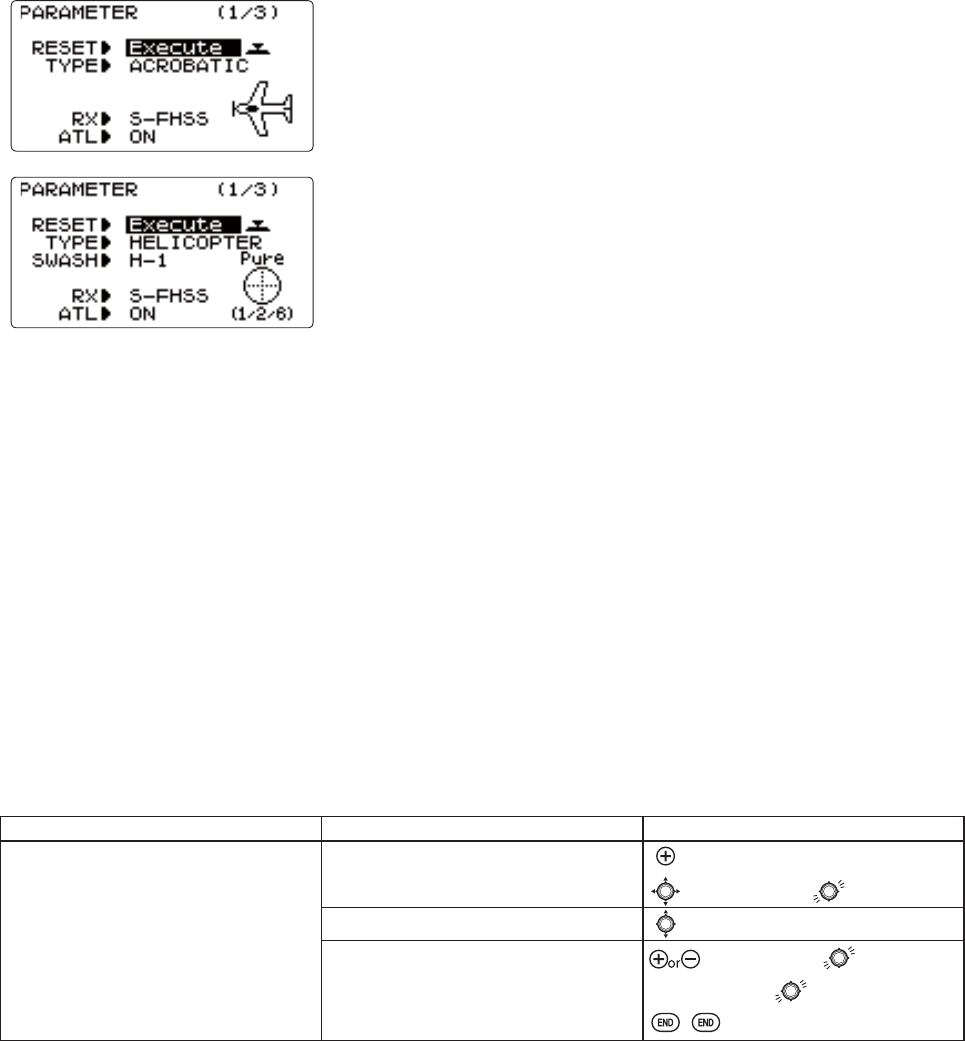
PARAMETER submenu:VHWVWKRVHSDUDPHWHUV\RXZRXOGOLNHO\VHWRQFHDQGWKHQQRWGLVWXUEDJDLQ
2QFH\RXKDYHVHOHFWHGWKHFRUUHFWPRGHO\RXZLVKWRZRUNZLWKWKHQH[WVWHSLVVHWWLQJXSWKHSURSHUSDUDPHWHUVIRUWKLV
VSHFL¿FPRGHO
:KDWLVWKHPRGHOVW\SH"
:KDWW\SHLVWKHUHFHLYHU¶VPRGXODWLRQ>SFHSS or FHSS]?
'RHVWKHPRGHOKDYHDQRUPDOWKURWWOHRQFKDQQHORUGR\RXQHHGIXOOUDQJH
trim on channel 3 (ATL)?
)LUVWLWLVLPSRUWDQWWRFOHDURXWDQ\ROGVHWWLQJVLQWKHPHPRU\IURPSULRUXVH
using the MODEL RESET: see p. 28.
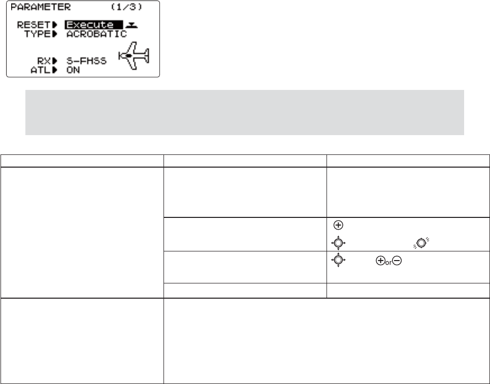
(ACRO)
(HELI)
MODEL TYPE: sets the type of programming used for this model.
The T8J has 20 model memories, which can each support:
RQH SRZHUHG DLUFUDIW ACRO PHPRU\ W\SH ZLWK PXOWLSOH ZLQJ DQG WDLO FRQ¿JXUDWLRQV 6HH WZLQ DLOHURQ VHUYRV WZLQ
elevator servos, ELEVON, and V-TAIL for further information.)
HLJKWKHOLFRSWHUVZDVKSODWHW\SHVLQFOXGLQJ&&306HH+HOLFRSWHUMODEL TYPE for details, p. 30.
%HIRUHGRLQJDQ\WKLQJHOVHWRVHWXS\RXUDLUFUDIW¿UVW\RXPXVWGHFLGHZKLFKMODEL TYPEEHVW¿WVWKLVSDUWLFXODUDLUFUDIW
(Each model memory may be set to a different model type.) If your transmitter is a T8JA, the default is ACRO. If it is a
7-+WKHGHIDXOWLVHELI(H1).
ACRO is the best choice for most powered airplanes:
ACRO adds:
SNAP-ROLL
AILEVATOR (twin elevator servo support)
)RUIXHOSRZHUHGDLUSODQHVIDLE-DOWN,THR-CUT,THROTTLE-NEEDLE mixing and THROTTLE DELAY programming.
,I\RXDUHXVLQJDKHOLMODEL TYPESOHDVHJRWRWKDWFKDSWHUQRZWRVHOHFWWKHSURSHUPRGHOW\SHDQGVXSSRUW\RXUPRGHO
VHWXS1RWHWKDWFKDQJLQJMODEL TYPEUHVHWVDOOGDWDIRUWKHPRGHOPHPRU\LQFOXGLQJLWVQDPH
GOAL of EXAMPLE: STEPS: INPUTS:
Select the proper MODEL TYPE for your
model. Ex: ACRO.
[NOTE: This is one of several functions
WKDWUHTXLUHVFRQILUPDWLRQWRPDNHD
FKDQJH2QO\FULWLFDOFKDQJHVUHTXLUH
DGGLWLRQDONH\VWURNHVWRDFFHSWWKH
FKDQJH@
Open the menu, then open the
PARAMETER submenu.
for 1 second.
to PARAMETER.
Go to MODEL TYPE.to TYPE.
Select proper MODEL TYPE.
Ex: ACRO.
&RQ¿UPWKHFKDQJH
&ORVH
to ACROBATIC.for 1 second.
Sure? displays. WRFRQ¿UP
31
Receiver modulation select (RX): sets the type of modulation transmitted.
The modulation of your receiver will determine whether you utilize SFHSS or FHSS setting in RX during transmission.
1RWHWKDW\RXKDYHWRWXUQ\RXUWUDQVPLWWHURIIDQGEDFNRQEHIRUHDPRGXODWLRQFKDQJHEHFRPHVHIIHFWLYH%HVXUH\RX
XQGHUVWDQGDQGVHWWKH)DLO6DIHF/S ) settings as you intended (see p. 48).
SFHSS/FHSS )+66*+]V\VWHPSFHSS mode/FHSS mode)
Adjustability:
SFHSSVHWWLQJIRUDOO)XWDED6)+66*PRGHUHFHLYHUVUHJDUGOHVVRI
number of channels.
FHSSVHWWLQJIRUDOO)XWDED)+66*PRGHUHFHLYHUVUHJDUGOHVVRI QXPEHU
of channels.
NOTE: When you change models in MODEL SELECT, if the new model is set to the other modulation type,
\RXPXVWF\FOHWKHWUDQVPLWWHUSRZHUWRFKDQJHPRGXODWLRQV7KHPRGXODWLRQZLOOÀDVKRQWKHKRPHVFUHHQ
to remind you until you do so. See p. 27, MODEL SELECT, for details.
GOAL of EXAMPLE: STEPS: INPUTS:
Change model 1 from SFHSS to FHSS. Confirm you are currently using the
proper model memory (Ex: 1)
2QKRPHVFUHHQFKHFNPRGHOQDPHDQG
number on top left and the modulation
on top right. If it is not the correct
model, use MODEL SELECT, p. 27.
Open the menu, then open PARAMETER
submenu.
for 1 second.
to PARAMETER.
Go to RX and change setting. to RX. to FHSS.
cycle power ÀDVKHVRQVFUHHQ
Cycle power. Cycle power.
Where next? Now that the model is in the proper modulation, the T8J should communicate
ZLWKWKHUHFHLYHU,ILWGRHVQRWFRQ¿UPWKHW\SHRIWKHUHFHLYHU
Change MODEL TYPE to airplane/helicopter: see p. 30.
Set F/S settings for when 2.4G receiver sees interference: see p. 48.
Utilize servo REVERSE: see p. 35.
Adjust servo travel with END POINT: see p. 36.
Set up dual/triple rates and exponential (D/R,EXP): see p. 39.
32
Adjustable travel limit (
ATL PDNHV WKH FKDQQHO TRIM LEVER (THROTTLE TRIM) effective only at low throttle,
disabling the trim at high throttle. This prevents pushrod jamming due to idling trim changes. This function defaults to ON.
If you are not using channel 3 for throttle, you may want trim operation the same as on all other channels. To do so, set ATL
to OFF. If you need the ATLWREHHIIHFWLYHDWWKHWRSRIWKHVWLFNLQVWHDGRIWKHERWWRPUHYHUVHWKHTHR-REV setting. Note
that this affects all models in the radio, not just the model you are currently editing. THR-REV, see p. 92.
GOAL of EXAMPLE: STEPS: INPUTS:
Change ATL from ON to OFF for battling
URERWVWDQNVDLUEUDNHVDQGRWKHU
channel 3 uses.
Open the menu, then open PARAMETER
submenu.
for 1 second.
to PARAMETER.
Go to ATL and Change. (Ex: to OFF)to ATL. to OFF.
Close.
Where next? Set up ELEVONIRUWDQNVW\OHFRQWUROWKURWWOHVWHHULQJRQRQH67,&.VHHS
Set up IDLE-DOWN and THR-CUTWRDGMXVWFKDQQHOVHUYRDWORZVWLFNVHHS
5HDVVLJQDX[LOLDU\FKDQQHOVH[IURPGLDOWRVZLWFKVOLGHUVHHS
Utilize servo REVERSE: see p. 35.
Adjust servo travel with END POINT: see p. 36.
Set up dual/triple rates and exponential(D/R,EXP): see p. 39.
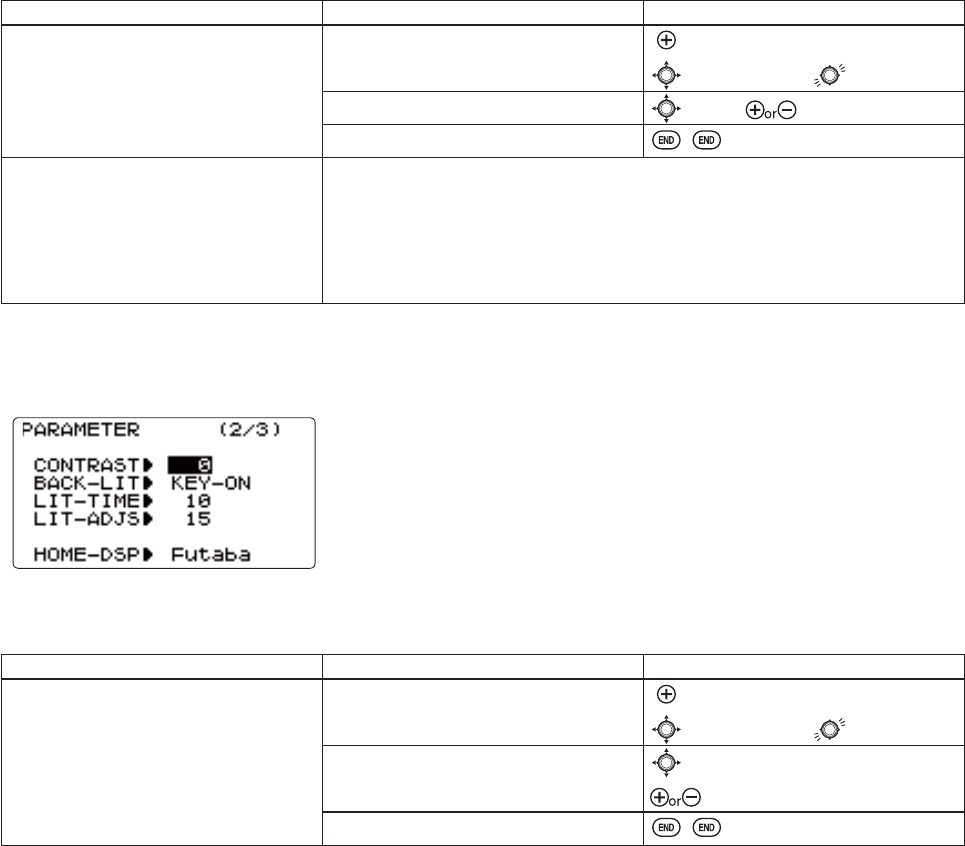
LCD screen adjustment (CONTRAST/BACK-LIT/LIT-TIME/LIT-ADJS):
Adjustability:
The following LCD screen adjustments are possible.
&RQWUDVWDGMXVWPHQW
%DFNOLJKWLQJPRGH
%DFNOLJKWLQJWLPH
%DFNOLJKWLQJEULJKWQHVVDGMXVWPHQW
GOAL of EXAMPLE: STEPS: INPUTS:
Change CONTRAST from 0 to +2. Open the menu, then open PARAMETER
submenu.
for 1 second.
to PARAMETER.
Go to CONTRAST and change setting.
(Ex: +2)
to CONTRAST.
to +2.
Close.
33
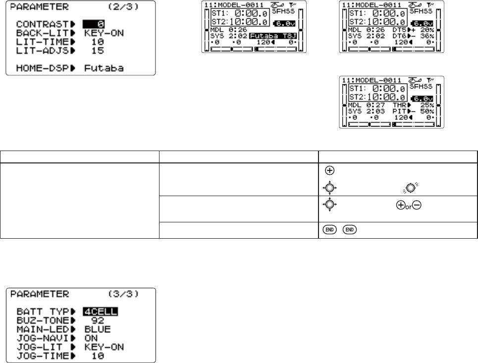
Home screen display mode selection (HOME-DSP): selects the display item in the home screen.
USER NAME: displays USER NAME in the home screen. (default)
The default USER NAMEDVVLJQHGE\WKHIDFWRU\LVWKH)XWDEDORJRVHHS
DT5/DT6: displays the current DT5 and DT6 position in the home screen.
THR/PIT: displays the current throttle and pitch position in the home screen. (HELI
only)
USER NAME mode DT5/DT6 mode
THR/PIT mode
GOAL of EXAMPLE: STEPS: INPUTS:
Change the display mode from USER
NAME to THR/PIT.
Open the menu, then open PARAMETER
submenu.
for 1 second.
to PARAMETER.
Go to HOME-DSP and change setting.
(Ex: THR/PIT)
to HOME-DSP. to THR/PIT.
Close.
Transmitter battery type (BATT TYP), LED adjustment (MAIN-LED/JOG-LED):
Adjustability:
The following transmitter adjustments are possible.
7UDQVPLWWHUEDWWHU\W\SHVHWWLQJ
%X]]HUWRQHW\SHVHWWLQJORZ ∼100:high)
3RZHU5)/('GLVSOD\FRORUVHOHFWLRQ2))FRORUV
-RJNH\/('GLVSOD\PRGHVHOHFWLRQ
BATT TYPE: chooses the battery type (5CELL/4CELL). The T8J transmitter offers a programmable low voltage alarm that warns
PRGHOHUVZKHQWKHWUDQVPLWWHUYROWDJHGURSV,I\RXDUHÀ\LQJZKHQWKLVDODUPVRXQGVSOHDVHODQGDVTXLFNO\DQGVDIHO\DV
SRVVLEOHWRDYRLGDQ\SRWHQWLDOGLI¿FXOWLHV5CELL1L0+FHOOVRU/L)HFHOOV4CELL: Dry 4 cells
$OZD\VVHWWKHEDWWHU\W\SHPDWFKHGWRWKHSRZHUVRXUFHXVHG(VSHFLDOO\ZKHQXVLQJD)XWDEDUHFKDUJHDEOHW\SHEDWWHU\
1L0+FHOOVRU/L)HFHOOVDOZD\VVHWWKHEDWWHU\W\SHWR&(//,IWKH7-LVXVHGDW&(//VHWWLQJWKHWLPH
from low battery alarm to stopping of the system will become extremely short.
BUZ-TONE: chooses the Buzzer tone (1:low ∼100:high).
MAIN-LEDFKRRVHVWKH/('GLVSOD\FRORU%/8(5('3853/(*5((1/,7%/8(<(//2::+,7(2))
JOG-NAVI217KH¿UVWEOLQNVKRZVWKHGLUHFWLRQZKLFKMRJNH\FDQRSHUDWH
JOG-LIT.(<217KHOLJKWRQLPPHGLDWHO\DIWHUMRJNH\RSHUDWLRQ$/:$<67KHOLJKWLVDOZD\VVZLWFKHGRQRU2))
JOG-TIME.(<21-RJ/('/LJKWLQJWLPH.
34
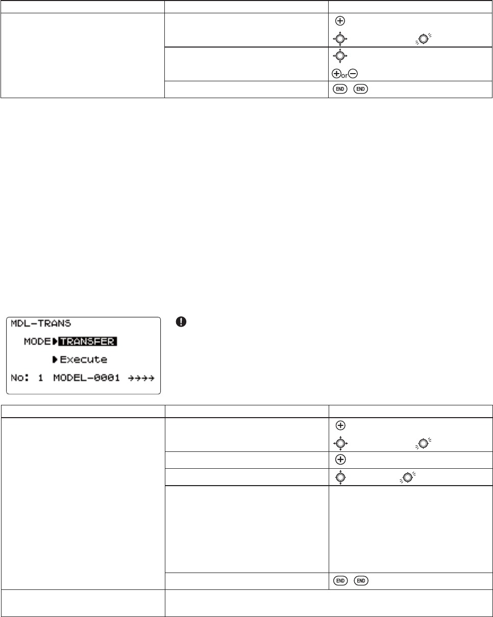
Model data transmission (
MDL-TRANS): Transmission of model data is possible with T8J transmitters. Data transfer is
performed on radio.
The present model is MDL-TRANS with each transmitter. As for a receiving side, the present model data is rewritten.
*T8J does not carry out normal operation during data transfer.
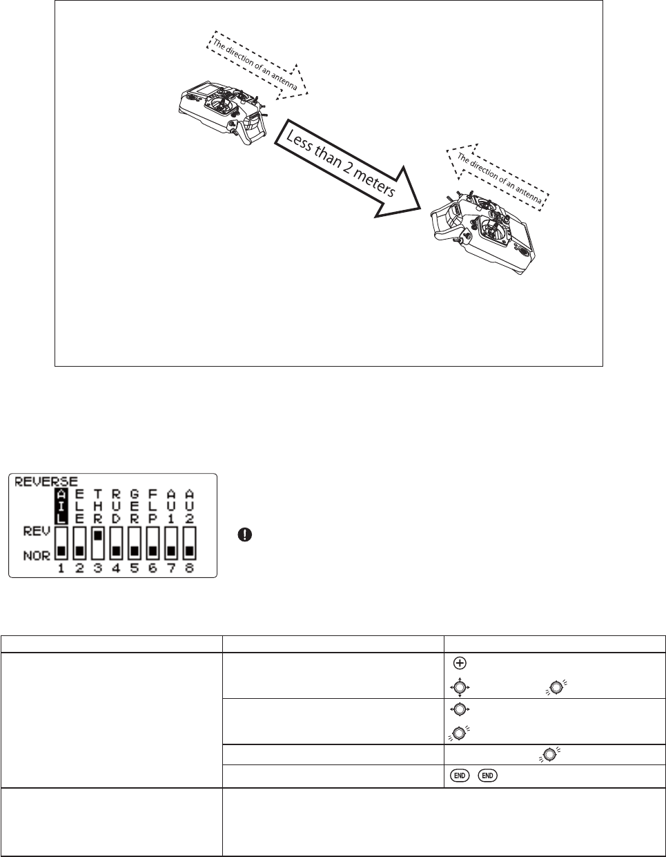
Always check servo direction prior to every flight as an additional
SUHFDXWLRQWRFRQ¿UPSURSHUPRGHOGDWHKRRNXSVDQGUDGLRIXQFWLRQ
NOTE:0'/75$16 EHWZHHQ WZR7-UDGLRV VKRXOG EHSHUIRUPHG ZLWKLQ D
PHWHUUDQJH
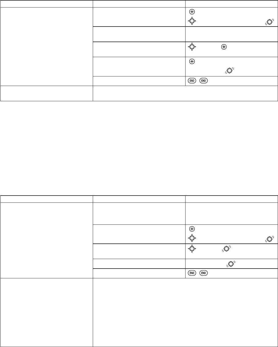
GOAL of EXAMPLE: STEPS: INPUTS:
MDL-TRANS is performed. Open MDL-TRANS function. for 1 second.
to MDL-TRANS.
The transmitting side is turned on. Select TRANSFER or RECEIVE.
Data is transmitted. to Execute. for 1 second .
Data Trans is for 10 seconds. T8J of a receiving side is set to RECEIVE,
and the same procedure is followed.
The completion of transmission
→"Complete"
Transmission failure
→"Failure"
Close.
Where next? SELECT a different model to edit or delete: p. 27.
NAME the model: p. 29.
GOAL of EXAMPLE: STEPS: INPUTS:
Change BATT TYPE from 4CELL to 5CELL. Open the menu, then open PARAMETER
submenu.
for 1 second.
to PARAMETER.
Go to BATT TYPE and change setting.
(Ex: 5CELL)
to BATT TYPE.
to 5CELL.
Close.
35
Servo reversing (REVERSE): changes the direction an individual servo responds to a CONTROL STICK motion.
)RU&&30KHOLFRSWHUVEHVXUHWRUHDGWKHVHFWLRQRQSWASH AFR (p. 75) before reversing any servos.
With the exception of CCPM helicopters, always complete your servo reversing prior to any other programming.
When using ACRO functions that control multiple servos, such as FLAPERON or V-TAIL, it may be confusing to determine
whether the servo needs to be reversed or a setting in the function needs to
be reversed. Refer to the instructions for each specialized function for further
details.
Always check servo direction prior to every flight as an additional
SUHFDXWLRQWRFRQ¿UPSURSHUPRGHOPHPRU\KRRNXSVDQGUDGLRIXQFWLRQ
NOTE: THR-REV is a special function that reverses the entire throttle control, including moving the trim functionality to
WKH6WLFN¶VXSSHUKDOI7RXVHTHR-REV: see p.92. This change affects all models in the radio.
GOAL of EXAMPLE: STEPS: INPUTS:
Reverse the direction of the elevator
servo.
Open REVERSE function. for 1 second.
to REVERSE.
Choose proper channel and set
direction. (Ex: ELE REV)
to ELE.
for 1 second.
&RQ¿UP\RXUFKDQJH Sure? displays.
Close.
Where next? Adjust servo travel with END POINT: see p. 36.
Set up dual/triple rates and exponential(D/R,EXP): see p. 39.
6HWXSÀLJKWWLPHUVVHHS
Set up trainer functions: see p. 44.
[ T8J of the transmits side ]
1. The data of a model to send is called by MDL-SEL.
2. MODE of MDL-TRANS is set to TRANSFER .
3. Execute .
[ T8J of the receives side ]
*It receives for 10 seconds.
1. The clear model is called by MDL-SEL.
2. MODE of MDL-TRANS is set to RECEIVE .
3. Execute .
MDL-TRANS
36
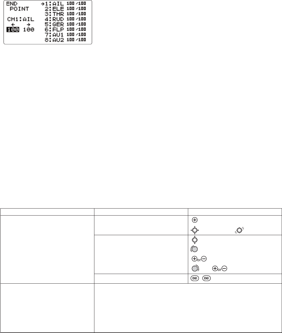
End Point of servo travel adjustment (END POINT): the most flexible version of travel adjustment available. It
LQGHSHQGHQWO\ DGMXVWV HDFK HQG RI HDFK LQGLYLGXDO VHUYR¶V WUDYHO UDWKHU WKDQ RQH VHWWLQJ IRU WKH VHUYR WKDW DIIHFWV ERWK
directions. Again, for CCPM helicopters, be sure to see SWASH AFR (see p. 75) prior to adjusting end points.
Adjustability:
&DQVHWHDFKGLUHFWLRQLQGHSHQGHQWO\
5DQJHVIURPQRVHUYRPRYHPHQWDWDOOWR$WDVHWWLQJWKH
WKURZ RI WKH VHUYR LV DSSUR[LPDWHO\ IRU FKDQQHOV DQG DSSUR[LPDWHO\
IRUFKDQQHOV
5HGXFLQJWKHSHUFHQWDJHVHWWLQJVUHGXFHVWKHWRWDOVHUYRWKURZLQWKDWGLUHFWLRQ
([DPSOHV
$GMXVWWKHWKURWWOHKLJKHQGWRDYRLGELQGLQJDWWKHFDUEXUHWRUDQGORZHQGWRDOORZIRUSURSHUFDUEXUHWRUFORVXUH
$GMXVWÀDSVRXSWUDYHOLVRQO\VXI¿FLHQWIRUVWUDLJKWDQGOHYHOÀLJKWWULPPLQJZLWKIXOOGRZQWUDYHO
END POINTPD\EHDGMXVWHGWRWRNHHSDVHUYRIURPPRYLQJRQHGLUHFWLRQVXFKDVÀDSVQRWLQWHQGHGWRDOVRRSHUDWHDV
spoilers.
5HWUDFWVHUYRVDUHQRWSURSRUWLRQDO&KDQJLQJEND POINT will not adjust the servo.
END POINT adjusts only the individual servo. It will have no effect on any other servo that is operated in conjunction with
this servo via mix or preset programming such as FLAPERON,AILEVATOR, etc. This is so that each individual servo can be
FDUHIXOO\¿QHWXQHGWRDYRLGELQGLQJDQGRWKHUFRQÀLFWV7RDGMXVWWKHWRWDOWUDYHORIDIXQFWLRQVXFKDVFLAPERONPDNH
WKHDGMXVWPHQWVLQWKDWIXQFWLRQVFRQWUROV)RU&&30KHOLFRSWHUVDGMXVWWKHWRWDOWUDYHORIWKHIXQFWLRQVXFKDVFROOHFWLYH
pitch, in SWASH AFR.
$GMXVWWKHOLQNDJHRUWKHEND POINT",WLVQHDUO\DOZD\VEHVWWRDGMXVW\RXUOLQNDJHVWRJHWDVFORVHDVSRVVLEOHSULRUWR
utilizing END POINT. The higher the END POINT setting, the better position accuracy and the more servo power available
DWQHDUO\DQ\SRVLWLRQH[FHSWLIXVLQJGLJLWDOVHUYRV+LJKHUEND POINT values also mean longer travel time to reach the
GHVLUHGSRVLWLRQDV\RXDUHXWLOL]LQJPRUHRIWKHVHUYRVWRWDOWUDYHO)RUH[DPSOHXVLQJEND POINT would give you
RQO\KDOIWKHVWHSV RI VHUYRWUDYHOPHDQLQJHYHU\ FOLFN RIWULPKDVWZLFHWKH HIIHFWDQGWKH VHUYR JHWVWKHUHLQKDOI WKH
time).
HQGSRLQWDQGPRYLQJWKHOLQNDJH WRUTXHDFFXUDF\EXWWUDQVLWWLPHWRJHWWKHUH
HQGSRLQWLQVWHDGRIDGMXVWLQJOLQNDJHV WUDYHOWLPHEXWWRUTXHDFFXUDF\
GOAL of EXAMPLE: STEPS: INPUTS:
Decrease the flap servo throw in the
XSZDUGGLUHFWLRQWRWRDOORZ
WULPPLQJRIOHYHOÀLJKWRQO\ DQG GRZQ
WUDYHOWRWRSUHYHQWELQGLQJ
Open END POINT function. for 1 second.
to END POINT.
&KRRVH SURSHU FKDQQHO DQG PRYH VWLFN
RUNQRELQGLUHFWLRQ\RXZDQWWRDGMXVW
DQGVHWVHUYRWKURZ([IODSXS
ÀDSGRZQ
to FLP.
ÀDSFRQWURO>GHIDXOWLVVR].
to 5%.*
VR. to 85%.*
Close.
Where next? Go to SERVOGLVSOD\WRFRQ¿UPWKHGHVLUHGHQGUHVXOWVHHS
Set up IDLE-DOWN and THR-CUT to slow/cut the engine: see p. 37.
Set up dual/triple rates and exponential(D/R,EXP): see p. 39.
6HWXSÀLJKWWLPHUVVHHS
Set up trainer functions: see p. 44.
Set up twin aileron servos: see p. 52.
Set up twin elevator servos: see p. 54.
<RXFDQUHVHWWRWKHLQLWLDOYDOXHVE\SUHVVLQJWKHDQGNH\VIRURQHVHFRQGVLPXOWDQHRXVO\
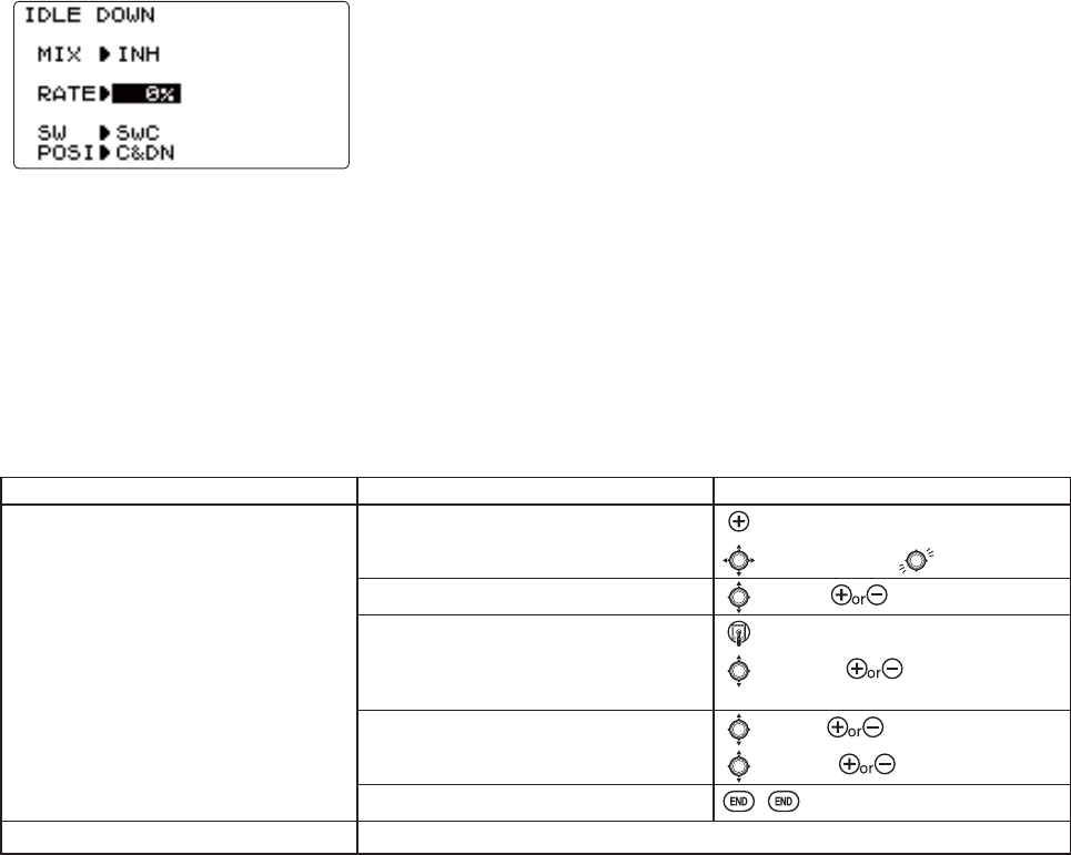
37
Engine idle management: IDLE-DOWN and THR-CUTIXQFWLRQVZKLFKZRUNZLWKWKHGLJLWDOTHROTTLE TRIM to provide
a simple, consistent means of engine operation. No more fussing with getting trim in just the right spot for landings or
WDNHRIIV)RUDGGLWLRQDOHQJLQHDGMXVWPHQWVVHHTHROTTLE-NEEDLE (p. 62) and THROTTLE DELAY (p. 63).
IDLE-DOWN (ACRORQO\ORZHUVWKHHQJLQHLGOHIRUVLWWLQJRQWKHUXQZD\SULRUWRWDNHRIIVWDOOVDQGVSLQVDQGODQGLQJV
7KHQRUPDOLGOHVHWWLQJLVDOLWWOHKLJKHUIRUHDVLHUVWDUWVDQGVDIHÀLJKWVZLWKOHVVULVNRIGHDGVWLFNV
Important note: The IDLE-DOWN function is not normally used when starting the
HQJLQHDQGLWVDFFLGHQWDORSHUDWLRQPD\NHHS\RXUHQJLQHIURPVWDUWLQJ7KH-
warns that IDLE-DOWN is on when the transmitter is turned on. Be sure to turn off
WKHIXQFWLRQRURYHUULGHWKHZDUQLQJE\SUHVVLQJWKHDQGNH\VIRURQH
second simultaneously.
This may be assigned to any switch/position. Some modelers accidentally assign IDLE-DOWN to one side of a switch
and THR-CUTWRWKHRWKHU7KHUHLVQR³QRUPDO´VHWWLQJWRVWDUWWKHHQJLQH%\GHIDXOWIDLE-DOWN is set to SWITCH C
FHQWHUDQGGRZQ7KLVZRUNVZHOOZLWKTHR-CUT also on SWITCH CGRZQ7KH6:,7&+XSLVQRUPDOÀLJKWVWDUWLQJ
center for slower maneuvers/landing, and down to cut the engine. If you assign IDLE-DOWN or THR-CUTWRWKHVSULQJ
loaded TRAINER SWITCH F (8JA) or H-+WKHQXVHWKHWUDLQHUIXQFWLRQ\RXPD\ULVNORVVRIWKURWWOHFRQWURORU
GHDGVWLFNIRU\RXUVWXGHQW
GOAL of EXAMPLE: STEPS: INPUTS:
Decrease the throttle setting to idle
with the flip of a switch for spins and
landings.
Open IDLE-DOWN function. for 1 second.
to IDLE-DOWN.
Activate the function. to MIX. to OFF.
With THROTTLE STICK at idle, adjust
the rate until engine idles as desired.*
THROTTLE STICK.
to RATE.until engine idles
as desired.
Optional: change switch assignment.
Choose desired switch and position.
to SW.to desired SWITCH.
to POSI. to desired position.
Close.
Where next? THR-CUT: see p. 38.
1RUPDOO\DYDOXHRI6HFXUHWKHIXVHODJHHQJLQHUXQQLQJ6HWWKHTHROTTLE STICK to idle. Adjust the IDLE-DOWNUDWHZKLOHÀLSSLQJWKH
VZLWFK21DQG2))XQWLOWKHGHVLUHGLGOHLVDFKLHYHG%HVXUHWRWKURWWOHXSSHULRGLFDOO\WRDOORZWKHHQJLQHWR³FOHDQRXW´DQGLGOHUHOLDEO\
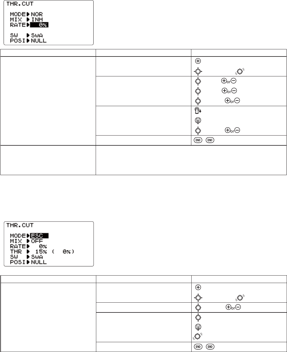
38
Throttle cut (THR-CUT): provides an easy way to stop the engine by flipping a switch (with THROTTLE STICK at
LGOH7KHPRYHPHQWLVODUJHVWDWLGOHDQGGLVDSSHDUVDWKLJKWKURWWOHWRDYRLGDFFLGHQWDOGHDGVWLFNV,QHELI, there is an
additional setting, THR-HOLD. See p. 78.
Throttle cut in the case of ESC use (THR-CUT): Sudden rotation may be carried out when releasing it using THR-CHT in
WKHFDVHRIDPRWRU$VHWXSRIZKLFKDIXQFWLRQLVQRWFDQFHOHGXQOHVVDWKURWWOHVWLFNEHFRPHVDVORZSRVLWLRQHYHQLILW
releases.
7KHVZLWFKVORFDWLRQDQGGLUHFWLRQPXVWEHFKRVHQ,WGHIDXOWVWRNULL to avoid
accidentally assigning it to a switch, which might result in an unintentional dead
VWLFNLQÀLJKW3OHDVHVHHIDLE-DOWN and THR-CUT on p. 37.
MODE is changed ESC from NOR.
GOAL of EXAMPLE: STEPS: INPUTS:
Decrease the throttle setting (at idle) to
VWRSWKHHQJLQHZLWKWKHÀLSRIDVZLWFK
(Note that you MUST assign a switch.
The default is NULL. We recommend
SWITCH C in the down position, with
IDLE-DOWN programmed to SWITCH C
in the center and down positions.)
Open THR-CUT function. for 1 second.
to THR-CUT.
Activate the function. Choose desired
switch, and the position which activates
the function.
to MIX. to OFF.
to SW. to SwC.
to POSI. to DOWN.
With THROTTLE STICK at idle, adjust
the rate until the engine consistently
VKXWVRIIEXWWKURWWOHOLQNDJHLVQRW
binding.*
SwC to down position.
THROTTLE STICK.
to RATE. until shuts off.
Close.
Where next? Set up dual/triple rates and exponential (D/R,EXP): see p. 39.
Set up TRAINER functions: see p. 44.
Set up twin aileron servos: see p. 52.
Set up twin elevator servos: see p. 54.
1RUPDOO\DVHWWLQJRILVVXI¿FLHQW9LHZLQJWKHFDUEXUHWRUEDUUHOXQWLOLWIXOO\FORVHVLVDGHTXDWHWRJHWDQDSSUR[LPDWHVHWWLQJWKHQWHVWZLWK
HQJLQHUXQQLQJWRFRQ¿UP
GOAL of EXAMPLE: STEPS: INPUTS:
MODE is changed ESC from NOR.
7+5SRVLWLRQUHOHDVHGLVPDGH
Open THR-CUT function. for 1 second.
to THR-CUT.
MODE is changed ESC from NOR.to MODE. to ESC.
7+5SRVLWLRQUHOHDVHGLVPDGH to THR.
THROTTLE STICK.
for 1 second.
Close.

39
Dual/triple rates and exponential (D/R,EXP): assigns adjusted rates and exponential.
Dual/Triple Rates: UHGXFHLQFUHDVHWKHVHUYR WUDYHO E\ÀLSSLQJD VZLWFK'XDO
rates affect the control listed, such as aileron, not just a single (ex: channel 1)
VHUYR )RU H[DPSOH DGMXVWLQJ DLOHURQ GXDO UDWH ZLOO DIIHFW ERWK DLOHURQ VHUYRV
when using FLAPERON or AIL-DIF DQG ERWK DLOHURQ DQG HOHYDWRU VHUYRV¶ WUDYHO
when using AILEVATOR or ELEVON or a CCPM helicopter.
Activation:
$Q\SWITCH, A-H,I\RXFKRRVHDSRVLWLRQVZLWFKWKHQWKDWGXDOUDWHLQVWDQWO\EHFRPHVDWULSOHUDWHVHHH[DPSOH
Adjustability:
5DQJHZRXOGGHDFWLYDWHWKHFRQWUROFRPSOHWHO\,QLWLDOYDOXH
$GMXVWDEOHIRUHDFKGLUHFWLRQACROLH8SGRZQOHIWULJKW([0RVWPRGHOVÀ\XSULJKWZLWKRXWDQ\HOHYDWRUWULP
EXWUHTXLUHVRPHGRZQHOHYDWRUZKHQLQYHUWHGMXVWWRPDLQWDLQOHYHOÀLJKW%\LQFUHDVLQJWKHGRZQWUDYHOE\WKHDPRXQW
required to hold the model inverted, the model now has equal travel available from level upright or level inverted.)
Exponential:FKDQJHVWKHUHVSRQVHFXUYHRIWKHVHUYRVUHODWLYHWRWKHVWLFNSRVLWLRQWRPDNHÀ\LQJPRUHSOHDVDQW<RXFDQ
PDNHWKHVHUYRPRYHPHQWOHVVRUPRUHVHQVLWLYHDURXQGQHXWUDOIRUUXGGHUDLOHURQHOHYDWRUDQGWKURWWOHH[FHSWHELI type
XVHTHROTTLE CURVE instead). (ACRO type—throttle EXP and THROTTLE CURVE cannot be activated simultaneously). Why
XVHH[SR"0DQ\PRGHOVUHTXLUHDODUJHDPRXQWRIWUDYHOWRSHUIRUPWKHLUEHVWWULFNV+RZHYHUZLWKRXWH[SRQHQWLDOWKH\
DUH³WRXFK\´DURXQGQHXWUDOPDNLQJWKHPXQSOHDVDQWWRÀ\DQGPDNLQJVPDOOFRUUHFWLRQVYHU\GLI¿FXOW$GGLWLRQDOO\E\
VHWWLQJGLIIHUHQWH[SRQHQWLDOVIRUHDFKUDWH\RXFDQPDNHWKHHIIHFWLYHQHVVRIVPDOOFRUUHFWLRQVVLPLODULQHDFKUDWHDVLQ
our example below.
The best way to understand exponential is to try it:
+DYLQJPDGHQRFKDQJHV\HWLQWKHD/R,EXP screen, move SWITCH AWR³GRZQ´ WRZDUG WKH THROTTLE/RUDDER
STICK).
&XUVRUGRZQWREXPDQGGLDOWR$OVRQHHGWRPRYHWKHVWLFNFRQWUROVWRKLJKOLJKWWKHVLGHV\RXZDQWWRVHW
0RYHSWITCH DXS+ROGWKHRUDDER STICKDWVWLFNDQGPRYHSWITCH D down.
1RWLFHKRZPXFKOHVVWUDYHOWKHUHLV
*RWRVWLFNDQGUHSHDW1RWLFHKRZWKHWUDYHOLVPXFKFORVHULIQRWLGHQWLFDO
Adjustability:
0RUHVHQVLWLYLW\DURXQGQHXWUDOSRVLWLYHH[SRQHQWLDOVHHH[DPSOH
/HVVVHQVLWLYLW\DURXQGQHXWUDOQHJDWLYHH[SRQHQWLDOVHHH[DPSOH
$GMXVWDEOHIRUHDFKGLUHFWLRQACRO)
)RUWKURWWOHH[SRQHQWLDOLVDSSOLHGDWWKHORZHQGWRKHOSQLWURDQGJDVROLQHHQJLQHVKDYHDOLQHDUWKURWWOHUHVSRQVHVRWKDW
HDFKVWLFNLQFUHDVHVHQJLQH530RIWKHDYDLODEOHUDQJH,QPRVWHQJLQHVWKLVUDQJHVIURP
Special note for helicopters: +HOLFRSWHU PRGHO W\SHV KDYH MXVW D VLQJOH UDWH IRU HDFK VZLWFK SRVLWLRQ UDWKHU WKDQ D UDWH
IRUHDFKVLGHRIWKHVHUYR¶VWUDYHOSHUVZLWFKSRVLWLRQ$GGLWLRQDOO\VHWWLQJWKHD/R,EXP for each switch position requires
FXUVRULQJEDFNWRWKHNo.VHWWLQJDQGFKDQJLQJWKHVZLWFKSRVLWLRQKHUH-XVWÀLSSLQJWKHVZLWFKGRHVQRWDIIHFWWKHVFUHHQ
VHWWLQJDOORZLQJGXDOUDWHVWREHDVVLJQHGZLWKLGOHXSDQGRWKHUIHDWXUHVRQFHUWDLQVZLWFKHVDQGGRHVQRWUHTXLUHSXWWLQJ
WKHPRGHOLQWKDWFRQGLWLRQWRPDNHPRGL¿FDWLRQV
Special note for conditions: The helicopter programming offers you the choice of Cond. This option allows you to have
D VHSDUDWH UDWH IRU HDFK RI WKH FRQWUROV DXWRPDWLFDOO\ VHOHFWHG ZKHQ FKDQJLQJ FRQGLWLRQV IRU D WRWDO RI ),9( UDWHV
available.
Simply change the switch choice to Cond and then:
+(/,SUHVVWKHJOG KEY to toggle through the 5 conditions while setting the rates.

40
GOAL of EXAMPLE: STEPS: INPUTS:
Set up dual rates and exponential in a
HELI model.
Open D/R,EXP.for 1 second.
to D/R,EXP.
Choose channel. to desired channel.
&KRRVH¿UVWVZLWFKSRVLWLRQ to No. to UP.
Set rate and exponential (Ex: high rate
H[SRQHQWLDO
to D/R. to 95%.
&RQ¿UP0% EXP.
Go to 2nd switch position and set rate
and exponential.
to No. to DN.
Repeat above.
2SWLRQDO LI XVLQJ D SRVLWLRQ VZLWFK
VHWUGUDWH
to No. to CT.
Repeat above.
2SWLRQDODVVLJQGXDOUDWHVWRKDYHRQH
IRUHDFKFRQGLWLRQ
to SW. to COND.
Repeat steps above to adjust for each
condition.
EXP Examples:
,WLVDQH[DPSOHRIDFRPPRQDLUSODQH
$,/(/(58'
,WPD\EHEHWWHUIRUDTXLFNRSHUDWLRQDFUREDWLFPDQHXYHUDLUSODQHWRVXEWUDFWJUHDWO\PRUH
3UREDEO\PD\EHVXI¿FLHQWDVDKHOLFRSWHU
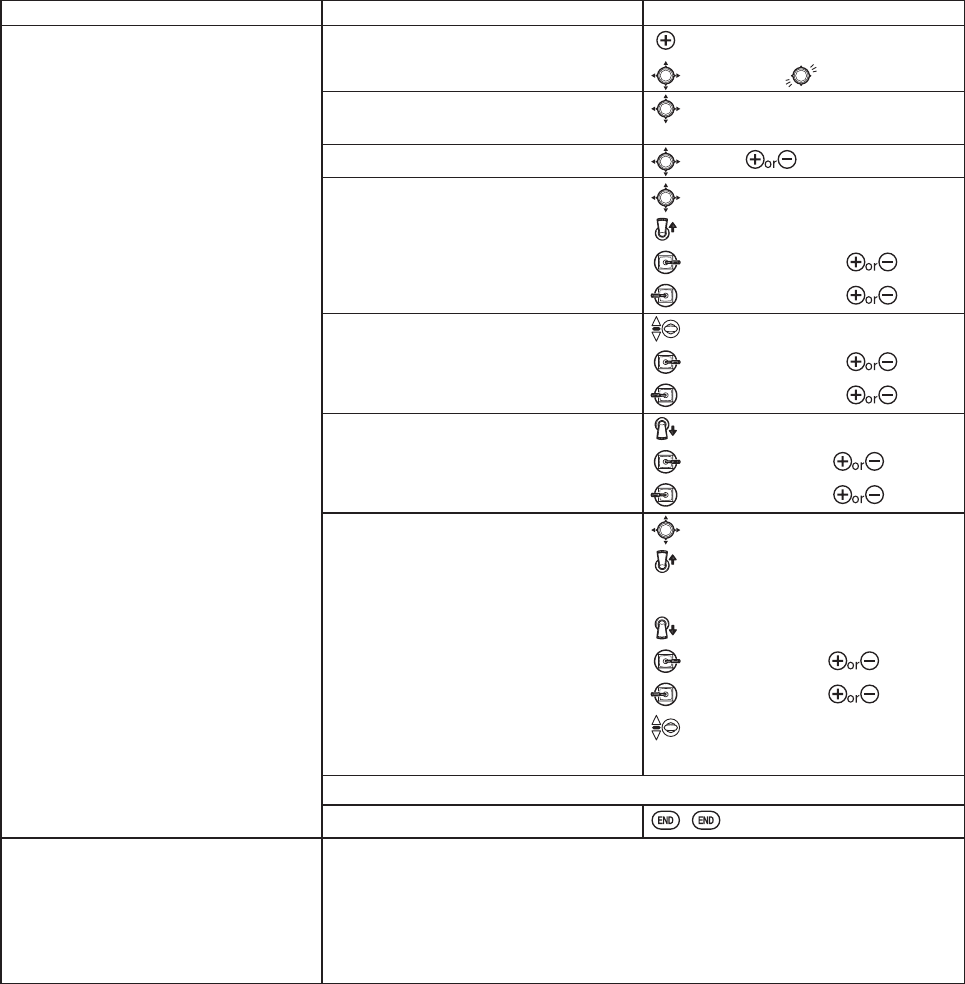
41
GOAL of EXAMPLE: STEPS: INPUTS:
Set up aileron triple rates on SWITCH
CZLWKWUDYHOVHWWLQJVRIQRUPDO
VORZUROODQGH[WUHPH
aerobatics) and exponential settings of
DQGUHVSHFWLYHO\LQDQ
ACRO model.
NOTE: This normal rate has no
exponential so it has a very linear,
normal feel. This slow roll rate has
positive exponential (the opposite of
what most people normally use), which
PDNHVWKHVHUYRVPRUHUHVSRQVLYH
DURXQGFHQWHU7KLVPDNHVWKHVHUYRV
feel the same around center in the
normal and low rates, but still gives a
YHU\VORZUROOUDWHDWIXOOVWLFN
The 3D rate (extreme aerobatics) has a
very high distance of travel nearly twice
that of the normal rate. Therefore, using
a very high negative exponential setting
softens how the servos respond around
FHQWHUVWLFN7KLVPDNHVWKHVHUYRV
UHVSRQGVLPLODUO\DURXQGFHQWHUVWLFN
for a more comfortable feel.
0DQ\PRGHOHUVOLNHWRVHWXSDOOWULSOH
UDWHVRQDVLQJOHSRVLWLRQVZLWFK
FUHDWLQJD³VORZDQGSUHWW\PRGH´
D³QRUPDOPRGH´DQGD³ZLOGVWXQWV
PRGH´DOOZLWKWKHIOLSRIDVLQJOH
switch. To do so, simply set up rates
for all 3 controls and assign all 3 to the
VDPHSRVLWLRQVZLWFK
Open D/R,EXP function. for 1 second.
to D/R,EXP.
Choose the channel to change
(Ex: aileron is already selected)
to desired channel.
2SWLRQDOFKDQJHVZLWFKDVVLJQPHQW to SW. to SwC.
Confirm switch is in desired position
DQGVHWUDWH([XS KLJKUDWH
to D/R.
C to up position.
AILERON STICK.WR
AILERON STICK.WR
Move SWITCH to 2nd rate position and
set this particular rate.
([FHQWHU ORZUDWH
C to center position.
AILERON STICK.WR
AILERON STICK.WR
2SWLRQDOLIXVLQJDSRVLWLRQ6:,7&+
PRYH 6:,7&+ WR UG SRVLWLRQ DQG VHW
WKLVUDWH([GRZQ 'UDWH
C to down position.
AILERON STICK
.WR
AILERON STICK
.WR
6HWHDFKUDWH¶VEXP.
([
to EXP.
C to up position.
&RQ¿UPEXP reads 0.
C to down position.
AILERON STICK
.WR
AILERON STICK
.WR
C to center position.
UHSHDWWRVHWORZUDWHH[SRWR
5HSHDWDERYHVWHSVIRUHOHYDWRUDQGUXGGHU
Close.
Where next? 6HWXSÀLJKWWLPHUVVHHS
Set up TRAINER functions: see p. 44.
Adjust the sensitivity of the trims: see p. 45.
Set up twin aileron servos: see p. 52.
Set up twin elevator servos: see p. 54.
6HWXSSURJUDPPDEOHPL[HVWRPHHW\RXUVSHFL¿FQHHGVVHHS
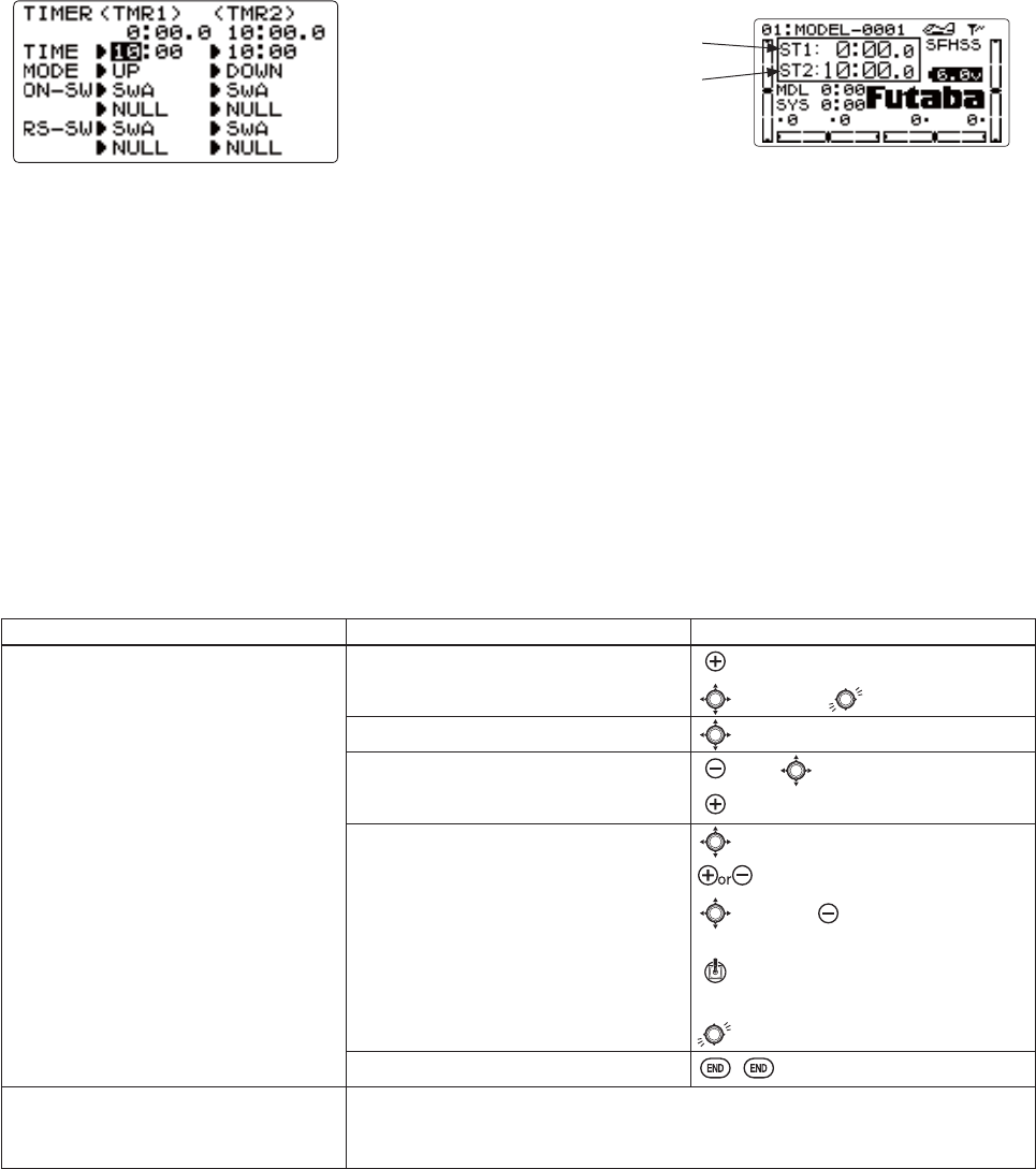
42
+RPHVFUHHQ
TIMER submenu VWRSZDWFK IXQFWLRQV FRQWUROV WZR HOHFWURQLF FORFNV )RU H[DPSOH WKHVH FORFNV PD\ EH XVHG WR NHHS
WUDFNRIWLPHUHPDLQLQJLQDFRPSHWLWLRQÀ\LQJWLPHRQDWDQNRIIXHODQGRUDPRXQWRIWLPHRQDEDWWHU\HWF
Adjustability:
&RXQWGRZQWLPHUVWDUWVIURPWKHFKRVHQWLPHGLVSOD\VWLPHUHPDLQLQJ,IWKHWLPHLVH[FHHGHGLW FRQWLQXHV WR FRXQW
below 0.
&RXQWXSWLPHUVWDUWVDWDQGGLVSOD\VWKHHODSVHGWLPHXSWRPLQXWHVVHFRQGV
&RXQWGRZQWLPHU6WRSW\SHVWDUWVIURPWKHFKRVHQWLPHGLVSOD\VWLPHUHPDLQLQJDQGVWRSVDW
,QGHSHQGHQWWRHDFKPRGHODQGDXWRPDWLFDOO\XSGDWHVZLWKPRGHOFKDQJH
,QHLWKHUTIMERPRGHWKHWLPHUEHHSVRQFHHDFKPLQXWH'XULQJWKHODVWWZHQW\VHFRQGVWKHUHVDEHHSHDFKWZRVHFRQGV
'XULQJWKHODVWWHQVHFRQGVWKHUHVEHHSVHDFKVHFRQG$ORQJWRQHLVHPLWWHGZKHQWKHWLPHVHOHFWHGLVUHDFKHG83
DOWN TIMER)
7R5HVHWFKRRVHWKHGHVLUHGWLPHUZLWKJOGNH\ZKLOHDWWKHVWDUWXSVFUHHQWKHQSUHVVDQGKROGJOGNH\IRUVHFRQG
$FWLYDWLRQ E\ HLWKHU GLUHFWLRQ RI SWITCH A-H, by THROTTLE STICK (
ST-THR) (Using the THROTTLE STICK is
FRQYHQLHQWLI\RXDUHNHHSLQJWUDFNRIIXHOUHPDLQLQJRUIRUDQHOHFWULFKRZPXFKEDWWHU\LVOHIWE\WKHSRZHU6:,7&+
(PWR-SW).
$OVRWKHUHVHWVZLWFKFDQEHDVVLJQHGSWITCH A-H)
GOAL of EXAMPLE: STEPS: INPUTS:
6HWWLPHUWRFRXQWGRZQPLQXWHV
being controlled by THROTTLE
STICKSRVLWLRQ7KLVLVXWLOL]HGWRNHHS
WUDFNRIDFWXDOWKURWWOHRQWLPHWREHWWHU
correlate with fuel/battery usage.
Open TIMER function. for 1 second.
to TIMER.
Go to <TMR2>.to 10 (<TMR2>).
Adjust time to 4 min. 30 sec., count
down.
to 4. to 00 (<TMR2>).
to 30.
Assign to THROTTLE STICK and set
trigger point.
to ON-SW (<TMR2>).
to ST-THR.
to NULL.to ↑Ļ LV VORZ DQG
is the timer ON.)
THROTTLE STICK to desired
SRVLWLRQ([VWLFN
for 1 second to set.
Close.
Where next? Adjust END POINTsDIWHU¿UVWÀLJKWWHVWVHHS
$GMXVWDX[LOLDU\FKDQQHODVVLJQPHQWVH[PRYHÀDSVWRDVZLWFKVHHS
Set up TRAINER functions: see p. 44.
TIMER<1>
TIMER<2>
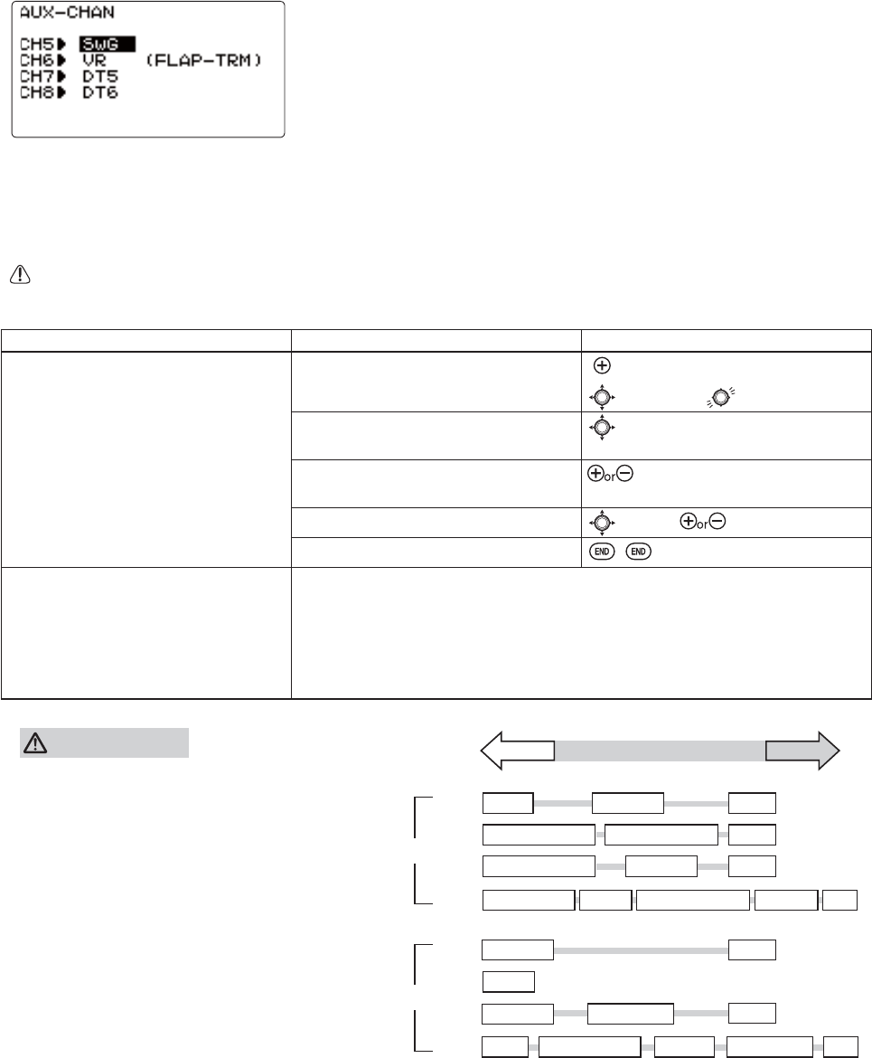
43
Auxiliary channel function (AUX-CHGH¿QHVWKHUHODWLRQVKLSEHWZHHQWKHWUDQVPLWWHUFRQWUROVDQGWKHUHFHLYHURXWSXWIRU
FKDQQHOV
Adjustability:
&KDQQHOVPD\EHDVVLJQHGWRDQ\SWITCH (A-H),TRIM LEVER (DT5
and DT6), or KNOB [VR].
0XOWLSOHFKDQQHOVPD\EHDVVLJQHGWRWKHVDPHVZLWFKWULPRUNQRE
&KDQQHOVVHWWR18//DUHRQO\FRQWUROOHGE\PL[HV([XWLOL]LQJ
channels for 2 rudder servos.)
,I GYRO SENSE,GOVERNOR, and THR-NEEDLE functions are activated, AUX-CH
settings of related channels become invalid automatically.
Related channels:
GYRO SENSE (ACRO/HELI): ch. 5, 7, or 8: see p. 64 and p. 87
GOVERNOR (HELI): ch. 7, or ch. 7 and 8: see p. 89.
THR-NEEDLE (ACRO/HELI): ch. 8: see p. 62.
5HPHPEHUWKDWLI\RXDVVLJQSULPDU\FRQWURORIDFKDQQHOWRDVZLWFKZKLFK\RXODWHUXVHIRURWKHUIXQFWLRQVOLNH
GXDOWULSOHUDWHVRUDLUEUDNHVHYHU\WLPH\RXXVHWKDWRWKHUIXQFWLRQ\RXZLOODOVREHPRYLQJWKHDX[LOLDU\FKDQQHO
GOAL of EXAMPLE: STEPS: INPUTS:
Assign flaps to the digital trim [DT5]
and set channel 7 to NULL in preparation
WRXVHLWDVDVPRNHV\VWHPFRQWUROWKH
VPRNHV\VWHPEHLQJDFWLYDWHGODWHUE\D
WKURWWOHWRFKPL[
Open AUX-CH function. for 1 second.
to AUX-CH.
Choose the channel to change. (ex: ch.
6.)
to Ch 6.
Change primary control. (ex: to digital
trim [DT5].)
to DT5.
Repeat as needed. (ex: ch. 7 to NULL.) to Ch 7. to NULL.
Close.
Where next? Programmable mixes: see p. 65.
Set up dual/triple rates and exponential (D/R,EXP): see p. 39.
Adjust SUB-TRIM of auxiliary channel to adjust center SWITCH position:
see p. 46.
Adjust END POINTs (sets end points of travel even when using a switch):
see p. 36.
The priority of AUX
higher rank Priority low rank
ACRO
CH5
CH5
CH6
CH6
CH7
CH7
CH8
CH8
HELI
PIT
FLAP TRIM
AIL-DIFF
AILVATOR
GYRO
GYRO
WARNING
Don't assign two or more functions to one channel.
Priority may be given to a higher rank function and
a low rank function may be canceled.
SW-G
SW-F
SW-C
FLAPERON VR
GYRO
GYRO
GYRO
DT5
DT6PIT
PIT
THR→NEEDL
GOVERNOR
THR→NEEDL GYRO GOVERNOR VRELE2
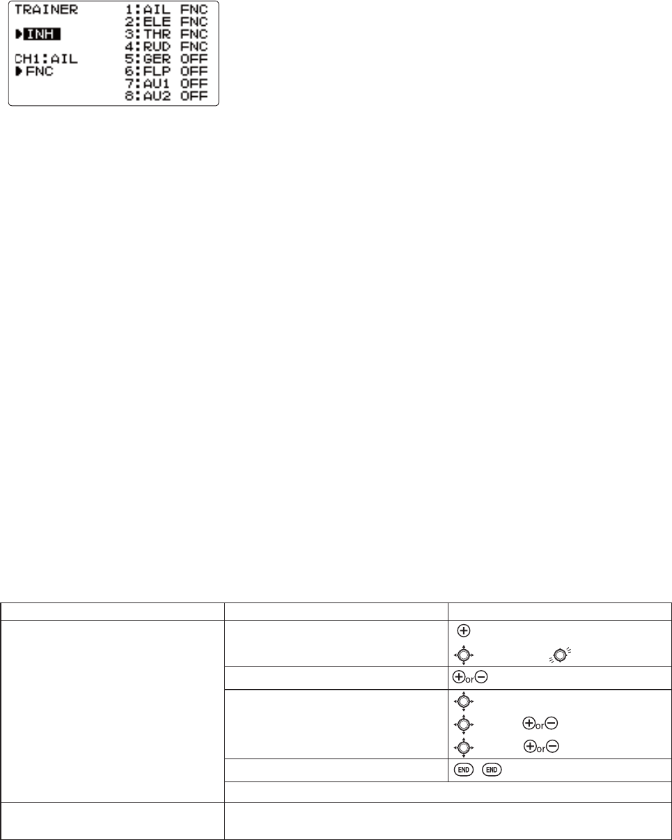
44
TRAINER: for training novice pilots with optional trainer cord connecting 2 transmitters. The instructor has several levels of
controllability.
Adjustability:
NOR: When the TRAINER SWITCH is ON, the channel set to this mode can
be controlled by the student. The set channel is controlled according to any
SURJUDPPLQJVHWDWWKHVWXGHQWVWUDQVPLWWHU
FNC: When the TRAINER SWITCH is ON, the channel set to this mode can
be controlled by the student, controlled according to any mixing set at the
LQVWUXFWRUVWUDQVPLWWHU
MIX: When the TRAINER SWITCH is ON, the channel set to this mode can be controlled by both the student and the
LQVWUXFWRUDFFRUGLQJWRDQ\PL[LQJVHWDWWKHLQVWUXFWRUVWUDQVPLWWHU$QGWKHVWXGHQWVPL[LQJUDWHLVDGMXVWDEOHGHIDXOW
>1RWH@+RZHYHULWEHFRPHVLQYDOLGHYHQLIWKHFKDQQHOLVQRWLQDVWXGHQWVWUDQVPLWWHU7KHFKDQQHOVHUYHVDVRSHUDWLRQE\
WKHLQVWUXFWRUVWUDQVPLWWHUDXWRPDWLFDOO\
OFF: The channel set to this mode cannot be controlled by the student even when the TRAINER SWITCH is ON. The set
channel is controlled by the instructor only, even when the TRAINER SWITCH is ON.
6:,7&+FRQWUROOHGE\VSULQJORDGHGSWITCH F (8JA) or H-+RQO\1RWDVVLJQDEOH
&RPSDWLELOLW\ 7KH - PD\ EH PDVWHU RU VWXGHQW ZLWK DQ\ )XWDED WUDQVPLWWHU FRPSDWLEOH ZLWK WKH FRUG 6LPSO\ SOXJ
the optional trainer cord (for 8J series, sold separately) into the trainer connection on each transmitter, and follow the
guidelines below.
([DPSOHV
:KHQWKURWWOHFROOHFWLYHDUHVHWWRFNC,
FKDQQHOKHOLFRSWHUSUDFWLFHLVSRVVLEOH
ZLWKDFKDQQHOWUDQVPLWWHU
6HWXSWKHPRGHOLQDVHFRQGWUDQVPLWWHU
and use NORPRGHWRTXLFNO\DQGVDIHO\
FKHFNSURSHURSHUDWLRQRIDOOIXQFWLRQV
Then, allow the student radio to fully fly
the model.
8VLQJNOR mode, set lower throws,
different exponentials, even different
auxiliary channel settings on the student
radio (if it has these features).
7RHDVHWKHOHDUQLQJFXUYHHOHYDWRUDQG
aileron may be set to the NOR or FNC mode,
ZLWKWKHRWKHUFKDQQHOVVHWWR2))DQG
controlled by the instructor.
GOAL of EXAMPLE: STEPS: INPUTS:
Turn on the TRAINER system and set up
so student has: fully functional control
of aileron and elevator to support
FLAPERON and AILEVATORQRUPDO
control of rudder to allow lowered
WUDYHODQGQRWKURWWOHFKDQQHOFRQWURO
(with the instructor for safety).
Open TRAINER function. for 1 second.
to TRAINER.
Activate TRAINER.to OFF.
Choose desired channel(s) and proper
training type(s).
past AIL and ELEGHIDXOW2.
to THR, to OFF.
to RUD, to NOR.
Close.
7(67VWXGHQWUDGLRIXQFWLRQIXOO\SULRUWRDWWHPSWLQJWRÀ\
Where next? Set up dual/triple rates and exponential (D/R,EXP) on student 8J: see p.39.
Reset trims on student 8J: see p.45.
Precautions:
1(9(5WXUQRQWKHVWXGHQWVWUDQVPLWWHUSRZHU
$/:$<6VHWWKHVWXGHQWWUDQVPLWWHUPRGXODWLRQPRGHWRPPM.
$VIRU D7-WUDQVPLWWHU330 VLJQDO LV DOZD\V VHQW E\ WKH WUDLQHU MDFN
regardless of the modulation mode.
%(685(WKDWWKHVWXGHQWDQGLQVWUXFWRUWUDQVPLWWHUVKDYHLGHQWLFDOWULP
VHWWLQJV DQG FRQWURO PRWLRQV 9HULI\ E\ VZLWFKLQJ EDFN DQG IRUWK ZKLOH
PRYLQJWKHFRQWUROVWLFNV
$OZD\V UHPRYH WKH VWXGHQW WUDQVPLWWHUV 5) PRGXOH LI LW LV D PRGXOH
type transmitter).
:KHQWKHTRAINER function is active, the snap roll function is deactivated.
Other functions, such as IDLE-DOWN and THR-CUT, which have been
DVVLJQHG WR WKH VDPH VZLWFK DUH QRW GHDFWLYDWHG$OZD\V GRXEOH FKHFN
your function assignments prior to utilizing the TRAINER function.
:KHQ\RXVHOHFWDGLIIHUHQWPRGHOWKHTRAINER function is deactivated in
the current model for safety reasons.
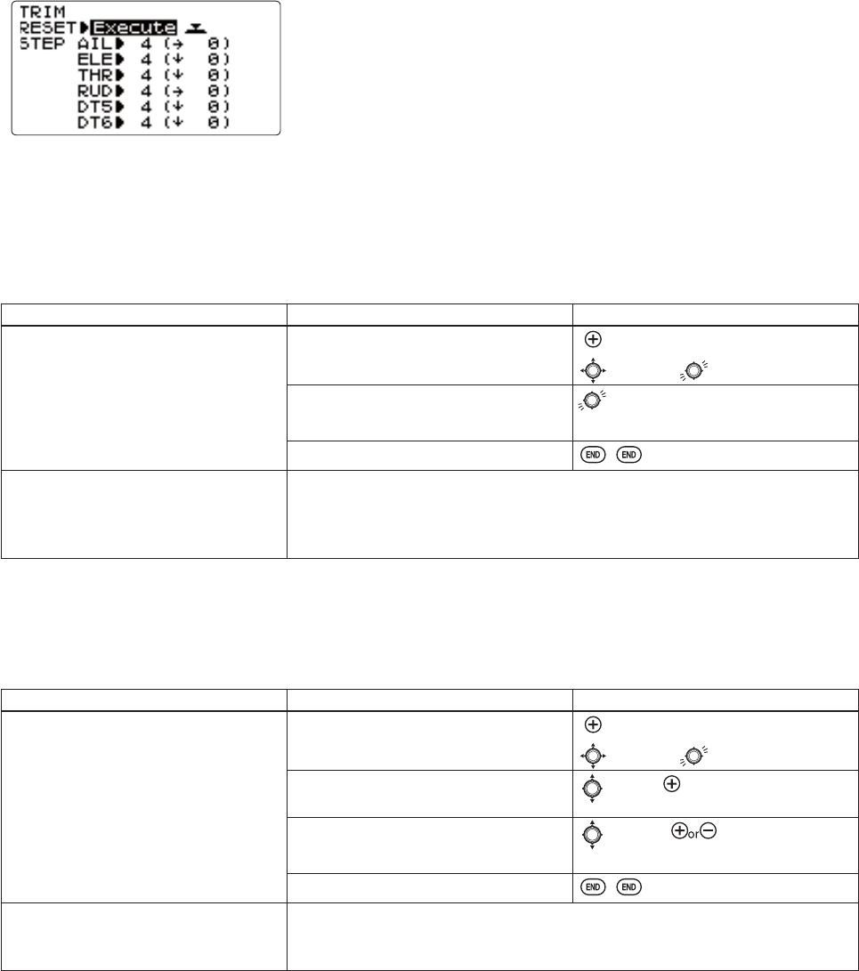
45
TRIM submenu: resets and adjust effectiveness of digital trims.
The 8J has digital trims which are different from conventional mechanical trim
sliders. Each TRIM LEVERLVDFWXDOO\DWZRGLUHFWLRQDOVZLWFK(DFKWLPHWKH
TRIM LEVER is pressed, the trim is changed a selected amount. When you
hold the TRIM LEVER, the trim speed increases. The current trim position is
graphically displayed on the start up screen. The TRIM submenu includes two
functions that are used to manage the trim options.
HELI models only: OFFSET is available in the idle ups. If OFFSET is inhibited, adjustment of the TRIM LEVERS will adjust
WKHWULPVIRUDOOÀLJKWFRQGLWLRQV,IOFFSET is active, then moving the trims within any one condition will affect only that
condition. See OFFSET, p. 83.
Trim reset (RESET): electronically centers the trims to their default values. Note that the SUB-TRIM settings and the trim
STEP rate are not reset by this command.
GOAL of EXAMPLE: STEPS: INPUTS:
Reset trims to neutral after having
DGMXVWHGDOOOLQNDJHV
Open TRIM submenu. for 1 second.
to TRIM.
Reset trims to neutral. for 1 second.
Beep sounds.
Close.
Where next? Adjust SUB-TRIMs: see p.46.
Adjust trim rate (STEP): see below.
Adjust END POINTs: see p. 36.
Set up dual/triple rates and exponential (D/R,EXP): see p. 39.
Trim step (STEP): changes the rate at which the trim moves when the TRIM LEVER is activated. It may be set from 1 to
40 units, depending on the characteristics of the aircraft. Most ordinary aircraft do well at about 2 to 10 units. Generally
ODUJHUWULPVWHSVDUHIRUPRGHOVZLWKODUJHFRQWUROWKURZVRUIRU¿UVWÀLJKWVWRHQVXUHVXI¿FLHQWWULPWRSURSHUO\FRUUHFWWKH
PRGHO6PDOOHUWULPVWHSVDUHODWHUXVHGWRDOORZYHU\¿QHDGMXVWPHQWVLQÀLJKW
GOAL of EXAMPLE: STEPS: INPUTS:
Double the sensitivity (larger step) of
the AILERON TRIM LEVERS for
a first flight of an aerobatic model to
HQVXUHVXI¿FLHQWUDQJHWRWULPWKHPRGHO
IRUOHYHOÀLJKW
Open TRIM submenu and choose the
STEP you wish to change. (Ex: aileron)
for 1 second.
to TRIM.
Adjust the size of the step.
(Ex: incr. to 8)
to AIL. to 8.
Repeat as desired for other channels. to ELEV. to new setting.
Repeat as needed.
Close.
Where next? Adjust sub trims: see p. 46.
Adjust END POINTs: see p. 36.
Set up dual/triple rates and exponential (D/R,EXP): see p. 39.
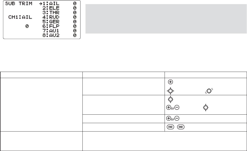
46
SUB-TRIMPDNHVVPDOOFKDQJHVRUFRUUHFWLRQVWRWKHQHXWUDOSRVLWLRQRIHDFKVHUYR5DQJHLVWRZLWKVHWWLQJ
the default being no SUB-TRIM.
:H UHFRPPHQG WKDW\RXFHQWHUWKHGLJLWDOWULPVEHIRUH PDNLQJSUB-TRIM
FKDQJHVDQGWKDW\RXWU\WRNHHSDOORIWKHSUB-TRIM values as small as
possible. Larger SUB-TRIM YDOXHV WKDW DIIHFW WKH VHUYRV UDQJH RI WUDYHO DUH
restricted on one side.
The recommended procedure is as follows:
PHDVXUHDQGUHFRUGWKHGHVLUHGVXUIDFHSRVLWLRQ
]HURRXWERWKWKHWULPVTRIM RESET menu) and the SUB-TRIMs WKLVPHQX
PRXQWVHUYRDUPVDQGOLQNDJHVVRWKDWWKHFRQWUROVXUIDFH¶VQHXWUDOLVDVFRUUHFWDVSRVVLEOHDQG
XVHDVPDOODPRXQWRISUB-TRIMWRPDNH¿QHFRUUHFWLRQV
GOAL of EXAMPLE: STEPS: INPUTS:
$GMXVWWKHIODSVHUYRVSUB-TRIM until
its center exactly matches the aileron
VHUYRVFHQWHUDVWKH\ZRUNWRJHWKHUDV
ÀDSHURQV
Open SUB-TRIM.for 1 second.
to SUB-TRIM.
Choose the channel to adjust, and adjust
the values until the surfaces match. (Ex:
ÀDS
to FLP
as needed. to each channel,
Repeat the other channel values. as needed.
Close.
Where next? Adjust trim steps: see p. 45.
Adjust END POINTs: see p. 36.
Set up dual/triple rates and exponential(D/R,EXP): see p. 39.
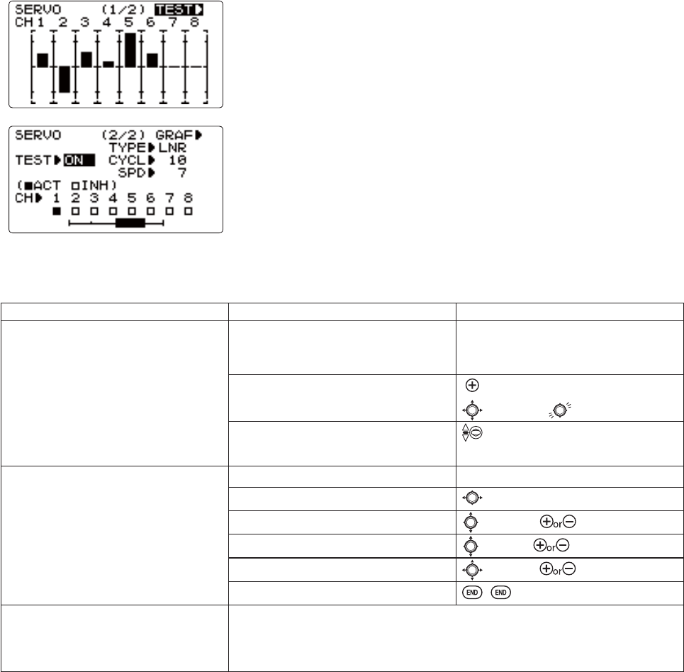
47
The servo submenu includes two features:
Real-time bar-graph display to demonstrate exactly what commands the
transmitter is sending to the servos. (This can be particularly handy in setting
up models with complicated mixing functions, because the results of each
VWLFNOHYHUNQREVZLWFKLQSXWDQGGHOD\FLUFXLWPD\EHLPPHGLDWHO\VHHQ
Servo cycle functionWR KHOS ORFDWH VHUYRSUREOHPVSULRUWRLQÀLJKWIDLOXUHV
FKDQQHOV
Adjustability:
&DQFKRRVH
servos to be cycled.
&\FOHW\SH/15/LQHDUPRGH-03-XPSPRGH
&\FOHWRVORZGHIDXOW
6HUYRVSHHGWRIDVWGHIDXOW
7KH VHUYR FKHFNHG KHUH >Ŷ@ FDUULHV RXW WHVW RSHUDWLRQ DW WKH WLPH RI 3RZHU
'RZQ0RGHH[FHSWIRU&+7KLVLVIRUDGLVWDQFHFKHFN
GOAL of EXAMPLE: STEPS: INPUTS:
9LHZ WKH UHVXOW RI UHDVVLJQLQJ FKDQQHO
6 from VRNQREWRWKUHHSRVLWLRQ
SWITCH C.
Complete desired programming
function. (Ex: in AUX-CH, move ch. 6 to
SWITCH C)
See AUX-CH for details. (p. 43.)
Open the SERVO function. for 1 second.
to SERVO.
Move each control to see the operation.
(Ex: SWITCH C in all positions)
C to center position.
Note change in position of ch. 6 servo.
Cycle the channel 6 servo.
Prepare servos to be cycled.
Plug in servos. POWER ON.
Open the servo cycle function. to GRAF>.
Set up cycle mode. (Ex: JMP mode) to TYPE. to JMP.
Choose channels to be cycled.
(Ex: ch. 6) to CH6. to ACT.
Cycle the channel 6 servo. to TEST.
End cycling and close.
Where next? Set up dual/triple rates and exponential (D/R,EXP): see p. 39.
Set up desired programmable mixes: see p. 65.
Set up dual aileron servos: see p. 52.
Set up dual elevator servos: see p. 54.
SERVO display and cycle submenu:GLVSOD\VUDGLRVRXWSXWWRFKDQQHOV
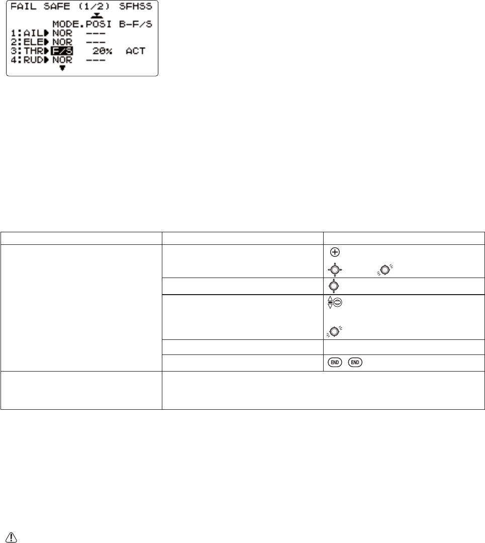
48
FailSafe (loss of clean signal and low receiver battery) submenu (F/S): sets responses in case of loss of signal or low Rx
battery.
FailSafe (F/S): instructs a 2.4G receiver what to do in the event radio interference is received.
Adjustability:
(DFKFKDQQHOPD\EHVHWLQGHSHQGHQWO\FHSS mode: ch2 only)
7KHNOR (normal) setting holds the servo in its last commanded position.
7KHF/S)DLO6DIHIXQFWLRQPRYHVHDFKVHUYRWRDSUHGHWHUPLQHGSRVLWLRQ
7KHVHWWLQJRIWKHF/S also applies to the Battery F/S (see below).
127(WKHVHWWLQJRIWKHWKURWWOHVF/S also applies to the Battery F/S (see
below)
([DPSOHV
7KH F/S setting is used in certain competitions to prevent the aircraft from flying away and doing potential damage
elsewhere. Conversely, the F/SVHWWLQJPD\DOVREHXVHGWRJRWRQHXWUDORQDOOVHUYRVKRSHIXOO\NHHSLQJWKHSODQHÀ\LQJ
long enough to regain control.
&RPSHWLWLRQPRGHOHUVRIWHQPDLQWDLQWKHNORIXQFWLRQVRWKDWEULHILQWHUIHUHQFHZLOOQRWDIIHFWWKHLUPRGHOVPDQHXYHU
6HWWKHWKURWWOHFKDQQHOVRWKDWWKHHQJLQHLGOHVZKHQWKHUHLVLQWHUIHUHQFHACRO7KLVPD\JLYHHQRXJKWLPHWRÀ\DZD\
from and recover from the radio interference and minimize damage if crashed.
)RUKHOLFRSWHUVNOR is typically the safest choice.
:HDOVRUHFRPPHQGVHWWLQJDJDVROLQHHQJLQHVHOHFWURQLFNLOOVZLWFKWRWKH2))SRVLWLRQLQWKHF/S function for safety reasons.
Updating F/S Settings: If you specify a F/SVHWWLQJWKH)DLO6DIHGDWDLVDXWRPDWLFDOO\WUDQVPLWWHG:KHQ\RXFKRRVHWKH
F/SPRGHFKHFNWKDW\RXUVHWWLQJVDUHDVGHVLUHGE\WXUQLQJRIIWKHWUDQVPLWWHUSRZHUVZLWFKDQGYHULI\LQJWKDWWKHVHUYRV
move to the settings that you chose.
GOAL of EXAMPLE: STEPS: INPUTS:
&KDQJHWKHUHFHLYHU)DLO6DIHFRPPDQG
IRUFKDQQHOJDVROLQHHQJLQHNLOO
switch) to a preset position.
NOTE: This is one of several
functions for which the radio requires
FRQ¿UPDWLRQWRPDNHDFKDQJH
Open F/S function. for 1 second.
to F/S.
Choose Channel to change. (ex: Ch. 8) to Ch 8.
Set and FRQ¿UP fail safe command. that controls channel 8 to desired
OFF position.
for 1 second to store.
Repeat as desired.
Close.
Where next? 5HDGEHORZIRULQIRUPDWLRQRQ%DWWHU\)DLO6DIH
Adjust END POINTs to gain proper F/S responses if needed: see p. 36.
Adjust SUB-TRIM to gain proper F/S responses if needed: see p. 46.
Battery FailSafe (F/S): a second battery low warning feature (separate from the transmitter low voltage warning). When
WKHDLUERUQHEDWWHU\YROWDJHGURSVEHORZDSSUR[LPDWHO\9WKH*UHFHLYHU¶VEDWWHU\F/S function moves the throttle
to a predetermined position. When the Battery F/SIXQFWLRQLVDFWLYDWHG\RXUHQJLQHZLOOPRYHWRLGOHLI\RXKDYHQWVHWD
position) or a preset position. You should immediately land. You may temporarily reset the Battery F/S function by moving
the THROTTLE STICK to idle. You will have about 30 seconds of throttle control before the battery function reactivates.
Adjustability:
NOR F/S setting for throttle results in Battery F/S going to the servo position reached by moving THROTTLE STICK to
the bottom with TRIM LEVERFHQWHUHG
F/S position setting for throttle results in Battery F/S also going to the same throttle servo position as the regular F/S.
,IXVLQJD9FHOOUHFHLYHUEDWWHU\LWLVYHU\OLNHO\WKDW\RXUEDWWHU\ZLOOEHUDSLGO\UXQQLQJRXWRIFKDUJHEHIRUH
EDWWHU\)DLO6DIHWDNHVRYHU,WLVQRWDJRRGLGHDWRFRXQWRQEDWWHU\)DLO6DIHWRSURWHFW\RXUPRGHODWDQ\WLPH7KLVLV
HVSHFLDOO\WUXHZKHQXVLQJDFHOOEDWWHU\

49
$,53/$1()81&7,216
Aircraft wing types (ACRO):
There are 3 basic wing types in aircraft models:
6LPSOH0RGHOXVHVRQHDLOHURQVHUYRRUPXOWLSOHVHUYRVRQD<KDUQHVVLQWRDVLQJOHUHFHLYHUFKDQQHODQGKDVDWDLO
This is the default setup and requires no specialized wing programming.
7ZLQ$LOHURQ6HUYRV0RGHOXVHVDLOHURQVHUYRVDQGKDVDWDLO6HH7ZLQ$LOHURQ6HUYRV
7DLOOHVV PRGHO À\LQJ ZLQJ 0RGHO XVHV ZLQJ VHUYRV ZRUNLQJ WRJHWKHU WR FUHDWH ERWK UROO DQG SLWFK FRQWURO 6HH
ELEVON.
Twin Aileron Servos (with a tail) (ACRO): Many current generation models use two aileron servos, plugged into two
VHSDUDWHUHFHLYHUFKDQQHOV,I\RXUPRGHOLVDÀ\LQJZLQJZLWKRXWVHSDUDWHHOHYDWRUVVHHELEVON, p. 53.)
%HQH¿WV
$ELOLW\WRDGMXVWHDFKVHUYRVFHQWHUDQGHQGSRLQWVIRUSHUIHFWO\PDWFKHGWUDYHO
5HGXQGDQF\IRUH[DPSOHLQFDVHRIDVHUYRIDLOXUHRUPLGDLUFROOLVLRQ
(DVHRIDVVHPEO\DQGPRUHWRUTXHSHUVXUIDFHE\QRWUHTXLULQJWRUTXHURGVIRUDVLQJOHVHUYRWRGULYHVXUIDFHV
+DYLQJPRUHXSDLOHURQWUDYHOWKDQGRZQWUDYHOIRUVWUDLJKWHUUROOV6HHDLOHURQGLIIHUHQWLDO
8VLQJWKHWZRDLOHURQVQRWRQO\DVDLOHURQVEXWDOVRDVÀDSVLQZKLFKFDVHWKH\DUHFDOOHGÀDSHURQV
6HWDQHJDWLYHSHUFHQWDJHWRUHYHUVHWKHRSHUDWLRQRIRQHRIWKHVHUYRV
Options:
FLAPERON:
8VHV&+IRUWKHVHFRQGVHUYR
$OORZVÀDSDFWLRQDVZHOODVDLOHURQDFWLRQIURPWKHDLOHURQV
3URYLGHVFLAP-TRIMIXQFWLRQWRDGMXVWWKHQHXWUDOSRLQWRIWKHÀDSHURQVIRUOHYHOÀLJKW
$OVRDOORZVDLOHURQGLIIHUHQWLDOLQLWVRZQSURJUDPPLQJLQVWHDGRIDFWLYDWLQJAIL-DIFF).
$LOHURQ'LIIHUHQWLDOAIL-DIFF):
8VHV&+IRUWKHQGVHUYR
/HDYHV&+IUHHIRUÀDSRSHUDWLRQVXFKDVÀDSHURQDQGÀDSDFWLRQWRJHWKHULQAIRBRAKE. (see p. 61).
$OORZVIRUPRUHXSDLOHURQWUDYHOWKDQGRZQIRUVWUDLJKWHUUROOV
You will need to choose either of FLAPERON or AIL-DIFFIRU\RXUPRGHOVVHWXS,I\RXQHHGWKHDLOHURQVWRDOVRRSHUDWHDV
ÀDSV\RXZLOOPRVWOLNHO\ZDQWWRXVHFLAPERON,I\RXUPRGHOKDVDLOHURQVHUYRVDQGÀDSVWKHQAIL-DIFF is probably
WKHHDVLHVWFKRLFH)RUGHWDLOVRQVHWWLQJXSDFRPSOH[DHUREDWLFSODQHSOHDVHYLVLWRXU)$4DWZZZIXWDEDUFFRP?IDT?
Many other setup examples are also available at this site.)
127(2QO\RQHRI WKH WKUHHZLQJW\SHIXQFWLRQVFLAPERON,AIL-DIFF, and ELEVON) can be used at a time. All three
IXQFWLRQVFDQQRWEHDFWLYDWHGVLPXOWDQHRXVO\7RDFWLYDWHDGLIIHUHQWZLQJW\SHWKH¿UVWPXVWEHGHDFWLYDWHG
GOAL of EXAMPLE: STEPS: INPUTS:
Deactivate FLAPERON so that AIL-DIFF or
ELEVON can be activated.
Open the FLAPERON function. for 1 second.
to FLAPERON.
Deactivate the function. to MIX. to INH.
Close function.
Where next? Set up AILE-DIFF (see p. 52) or ELEVON (see p. 53).
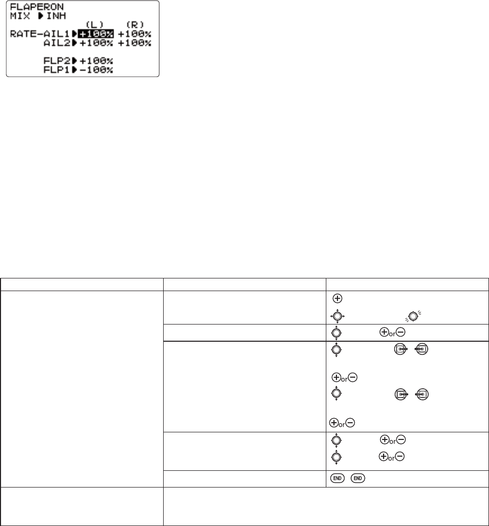
50
Using FLAPERON (ACRO):
The FLAPERON mixing function uses one servo on each of the two ailerons,
DQG XVHV WKHP IRU ERWK DLOHURQ DQG ÀDS IXQFWLRQ )RU ÀDS HIIHFW WKH DLOHURQV
raise/lower simultaneously. Of course, aileron function (moving in opposite
directions) is also performed.
Once FLAPERONLVDFWLYDWHGDQ\WLPH\RXSURJUDP&+RUÀDSLHELEVATOR-FLAP mixing), the radio commands both
VHUYRVWR RSHUDWH DVÀDSV7KHDPRXQW RIWUDYHODYDLODEOH DVÀDSVLV LQGHSHQGHQWO\DGMXVWDEOH LQ FLAPERON. A trimming
feature is also available (see FLAP-TRIM WR DGMXVW ERWK QHXWUDO SRVLWLRQV WRJHWKHU IRU VWUDLJKWDQGOHYHO ÀLJKW RU VOLJKW
LQFUHDVHVGHFUHDVHVRIWKHÀDSDQJOHEND POINT and SUB-TRIM both still adjust each servo individually.
Adjustability:
(DFKDLOHURQVHUYRVXSWUDYHOFDQEHVHWVHSDUDWHIURPLWVGRZQWUDYHOFUHDWLQJDLOHURQGLIIHUHQWLDO6HHH[DPSOH
(DFKDLOHURQVHUYRVWUDYHOZKHQDFWXDWHGDVDÀDSLVVHSDUDWHO\DGMXVWDEOH
127($FWLYDWLQJÀDSHURQVRQO\PDNHVWKHDLOHURQVZRUNDVDLOHURQVDQGWHOOVWKHUDGLRKRZIDU\RXZDQWWKHPWRPRYH
DVÀDSV,IGHVLUHG\RXWKHQDFWLYDWHRWKHUSURJUDPPLQJWKDWPRYHVWKHPDVÀDSV
FLAP-TRIMLVWKHÀDSWULPPLQJIHDWXUHWKDWDOORZVWKHÀDSVWRPRYHLQUHDFWLRQWRWKHFKDQQHOFRQWURO,WLVPHDQWRQO\
IRUWULPPLQJWKHÀDSVFHQWHUEXWFDQDOVREHXVHGDVIXOOÀDSFRQWURO6HHS
AIRBRAKELVDIHDWXUHWKDWGURSVÀDSHURQVDVÀDSDQGDOVRFRPSHQVDWHVZLWKHOHYDWRULIGHVLUHG6HHS
ELEVATOR-FLAPZRXOGDGGHOHYDWRUPL[LQJLQWRWKHÀDSPRYHPHQWIURPWKHÀDSGLDODIWHUFLAP-TRIM is activated.
GOAL of EXAMPLE: STEPS: INPUTS:
Activate twin aileron servos, FLAPERON.
,QSXWOHVVGRZQWUDYHOWKDQXS
travel (aileron differential) within the
FLAPERON programming. (Decrease right
DLOHURQLVGRZQWUDYHOWRGHFUHDVH
OHIWDLOHURQVGRZQWUDYHOWR
$GMXVWWRWDOÀDSWUDYHODYDLODEOHWR
of aileron travel available.
Open the FLAPERON function. for 1 second.
to FLAPERON.*
Activate the function. to MIX. to ACT.
Optional: adjust the up/down travel
VHSDUDWHO\IRU WKHVHUYRV([
GRZQ
to AIL1.AILERON
STICK.
to 90%.
to AIL2.AILERON
STICK.
to 90%.
2SWLRQDO DGMXVW WKH DLOHURQV WUDYHO VR
WKH\PRYHDVÀDSV([HDFKVHUYRÀDS
travel to 50%
to FLP2. to +50
to FLP1. to -50
Close menu.
Where next? Set FLAP-TRIM: see p. 51.
Set up AIRBRAKE mix: see p. 61.
9LHZDGGLWLRQDOPRGHOVHWXSVRQWKHLQWHUQHWZZZIXWDEDUFFRPIDT
* If you receive an error message that OTHER WING MIXING "ON", you must deactivate AIL-DIFF or ELEVON.
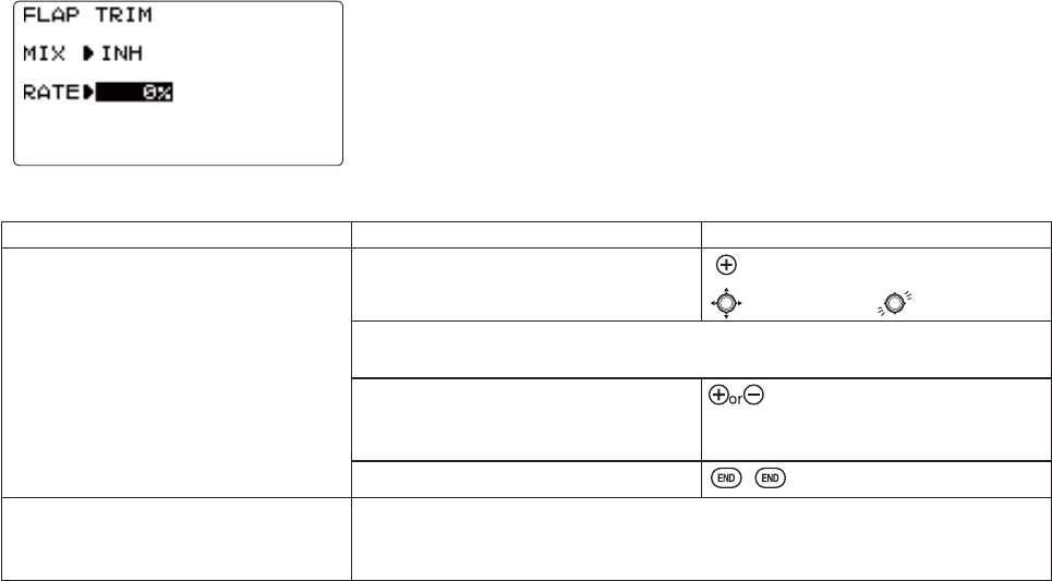
51
Using FLAP-TRIM WRDGMXVWÀDSHURQV (ACRO)
GOAL of EXAMPLE: STEPS: INPUTS:
Add FLAP-TRIMWRDOORZWKHPRGHOV
DLOHURQVWREHWULPPHGWRJHWKHUDVÀDSV
at any time during the flight,with a
maximum travel of 5%RIWKHWRWDOÀDS
travel set in FLAPERON.
Open the FLAP-TRIM function. for 1 second.
to FLAP-TRIM.
The function is automatically activated with FLAPERONKRZHYHUWKHGHIDXOW
travel is 0.
Adjust the travel available to the
ÀDSHURQVZKHQWXUQLQJWKH&+DIAL.
(Ex: 5%).
to +5%.
Close menu.
Where next? $GMXVWLQGLYLGXDOVHUYRVSUB-TRIMs: see p. 46 and END POINTs: see p. 36.
Set up AIRBRAKE mix: see p. 61 and ELE-FLAP mix: see p. 59.
9LHZDGGLWLRQDOPRGHOVHWXSVRQWKHLQWHUQHWZZZIXWDEDUFFRP?IDT?
FLAP-TRIMDVVLJQVWKHSULPDU\ÀDSHURQFRQWURO>VR@WRDOORZWULPPLQJLQÀLJKW
RIWKHÀDSDFWLRQRIÀDSHURQV1RWHHYHQLIFLAP-TRIM is made active with AIL-
DIFF, it will not have any effect. The ONLY function that allows control of the
DLOHURQVDVÀDSVLQWKHAIL-DIFFFRQ¿JXUDWLRQLVAIRBRAKE.) Most modelers use
AIRBRAKERUSURJUDPPDEOHPL[HVWRPRYHWKHÀDSVWRDVSHFL¿HGSRVLWLRQYLD
movement of a switch.
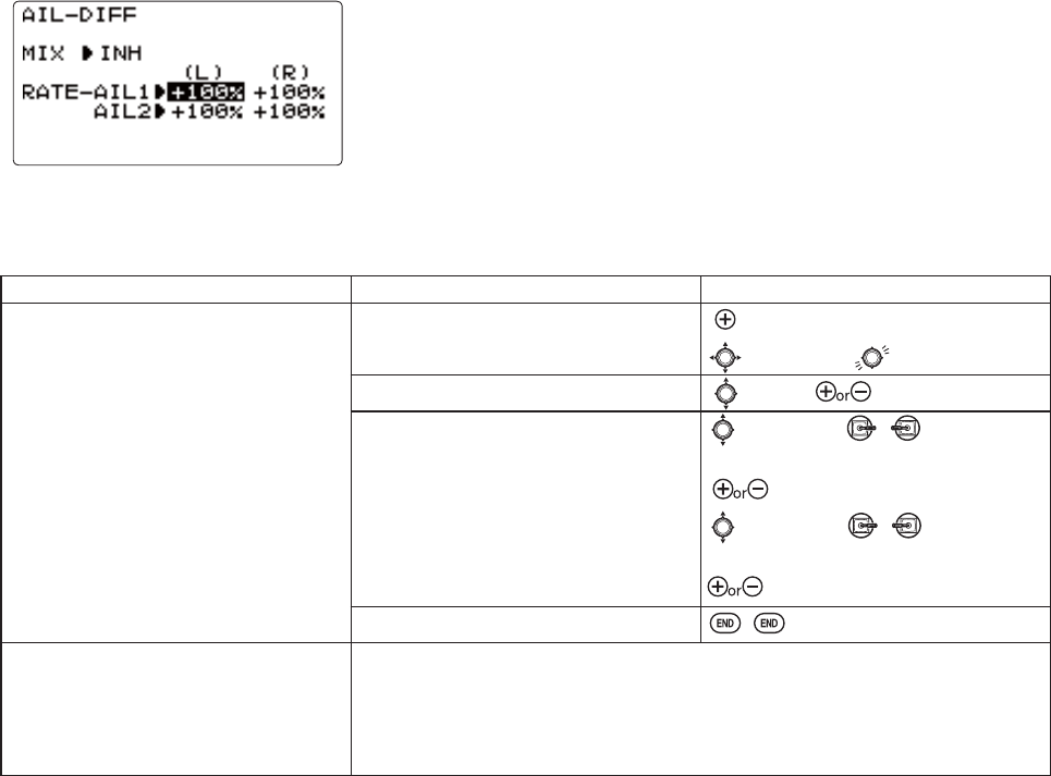
52
Using Aileron Differential (AILE-DIFF)(ACRO):
$LOHURQGLIIHUHQWLDOLVSULPDULO\XVHGRQRUVHUYRZLQJVZLWKRQHVHUYRV
RSHUDWLQJLQERDUGIODSVRQ&+DQGAILE-DIFF controlling proper aileron
RSHUDWLRQRIDLOHURQ VHUYRV SOXJJHGLQWR&+DQG &+7KHDLOHURQVFDQ
QRWEHPRYHGOLNHÀDSVZKHQXVLQJAILE-DIFF, except if using AIRBRAKE (Note
WKDWHYHQLI \RX PDNHFLAP-TRIM active while using AILE-DIFF, it will not have
any effect. ONLY AIRBRAKE controls the ailerons as flaps in the AILE-DIFF
FRQ¿JXUDWLRQ
GOAL of EXAMPLE: STEPS: INPUTS:
Activate twin aileron servos using AIL-
DIFF.
Note that the function defaults to no
difference in down travel vs. up travel.
If you want differential travel, simply
DGMXVWHDFKVLGH([
Open the AIL-DIFF function. for 1 second.
to AIL-DIFF.*
Activate the function. to MIX. to ACT.
Optional: adjust the up/down travel
separately for the two servos.
(Ex: adjust to 90%.)
to AIL1.AILERON
STICK.
to 90%.
to AIL2.AILERON
STICK.
to 90%.
Close menu.
Where next? $GMXVWLQGLYLGXDOVHUYRVSUB-TRIMs: see p. 46 and END POINTs: see p. 36.
Set up AIRBRAKE mix: see p. 61.
Set up ELE-FLAPPL[RQO\LIPRGHOKDVDÀDSVHUYRLQ&+VHHS
Set up SNAP-ROLL)XQFWLRQVHHS
9LHZDGGLWLRQDOPRGHOVHWXSVZZZIXWDEDUFFRP?IDT?
*If you receive an error message that OTHER WING MIXING "ON", you must deactivate ELEVON or FLAPERON.
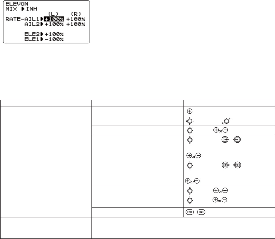
53
Aircraft tail types (ACRO):
There are 4 basic tail types in aircraft models:
6LPSOH0RGHOXVHVRQHHOHYDWRUVHUYRDQGRQHUXGGHUVHUYRRUPXOWLSOHVHUYRVRQD<KDUQHVV7KLVLVWKHGHIDXOW
'XDO(OHYDWRUVHUYRV0RGHOXVHVHOHYDWRUVHUYRVVHHAILVATOR p. 54.
7DLOOHVVPRGHO0RGHOXVHVZLQJVHUYRVWRJHWKHUWRFUHDWHUROODQGSLWFKFRQWUROVHHELEVON. p. 53.
V-TAIL. Model uses 2 surfaces, at an angle, together to create yaw and pitch control. see V-TAIL. p. 55.
1RWH2QO\RQHRIWKHWKUHHWDLOW\SHIXQFWLRQVAILEVATOR,V-TAIL, and ELEVON) can be used at a time. The radio provides a
ZDUQLQJDQGZLOOQRWDOORZWKHDFWLYDWLRQRIDQRWKHUWDLOW\SHXQWLOWKH¿UVWLVGHDFWLYDWHG$QHUURUPHVVDJHRIOTHER WING
MIXING "ON" will display.
Using ELEVON(ACRO XVHG ZLWK GHOWD ZLQJV À\LQJ ZLQJV DQG RWKHU WDLOOHVV DLUFUDIW WKDW FRPELQH DLOHURQ DQG HOHYDWRU
functions, using two servos, one on each elevon. The aileron/elevator responses of each servo can be adjusted
LQGHSHQGHQWO\7KLVLVDOVRSRSXODUIRUJURXQGPRGHOXVHVXFKDVWDQNVZKLFKGULYHWZRPRWRUVWRJHWKHUIRUIRUZDUGDQG
RQHPRWRUIRUZDUGRQHEDFNZDUGIRUWXUQLQJ
Adjustability:
5HTXLUHVXVHRI&+DQG&+
,QGHSHQGHQWO\DGMXVWDEOHDLOHURQWUDYHODOORZVDLOHURQGLIIHUHQWLDO
,QGHSHQGHQWO\DGMXVWDEOHHOHYDWRUWUDYHODOORZVIRUGLIIHUHQFHVLQXSYVGRZQ
travel.
NOTE: If ELEVON is active, you cannot activate FLAPERON,AILE-DIFF, or AILEVATOR. An error message OTHER WING MIXING
"ON" displays and you must deactivate the last function to activate ELEVON.
127(%HVXUHWRPRYHWKHHOHYDWRUDQGDLOHURQVWLFNVWRIXOOGHÀHFWLRQGXULQJVHWXS,IODUJHWUDYHOVDUHVSHFL¿HGZKHQ
the AILERON and ELEVATOR STICKS are moved at the same time the controls may bind or run out of travel.
()RUGHWDLOVRQVHWWLQJXSDFRPSOH[DHUREDWLFSODQHSOHDVHYLVLWZZZIXWDED
UFFRP?IDT?0DQ\RWKHUVHWXSH[DPSOHVDUHDOVRDYDLODEOHDWWKLVORFDWLRQ
GOAL of EXAMPLE: STEPS: INPUTS:
Activate ELEVON.
Adjust aileron down travel to 90% of up
travel, creating aileron differential.
Open the ELEVON function. for 1 second.
to ELEVON.*
Activate the function. to MIX. to ACT.
Optional: adjust the up/down travel
VHSDUDWHO\IRUWKHVHUYRVDVDLOHURQV
(Ex: down to 90%
to AIL1.AILERON
STICK.
to 90%.
to AIL2.AILERON
STICK.
to 90%.
Optional: adjust the elevator travel of
HDFKVHUYR([ULJKWVHUYRHOHYWUDYHO
to 98%, left to 105%
to ELE2. to 98
to ELE1. to 105
Close menu.
Where next? $GMXVWLQGLYLGXDOVHUYRVSUB-TRIMs: see p. 46 and END POINTs: see p. 36.
Set up dual/triple rates and exponential(D/R,EXP): see p. 39.
9LHZDGGLWLRQDOPRGHOVHWXSVRQWKHLQWHUQHWZZZIXWDEDUFFRP?IDTKWPO
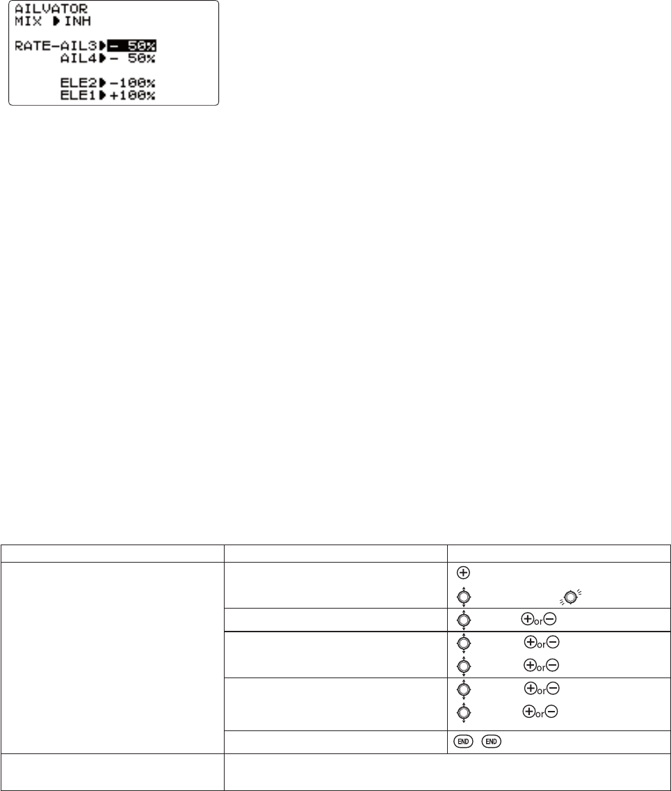
54
Dual Elevator Servos (with a rudder) (AILEVATOR) (ACRO): Many models use two elevator servos, plugged in separate
UHFHLYHUFKDQQHOV)O\LQJZLQJVZLWKRXWDVHSDUDWHDLOHURQFRQWUROXVHELEVON9VKDSHGWDLOPRGHOVXVHV-TAIL, p. 55.)
%HQH¿WV
$ELOLW\WRDGMXVWHDFKVHUYRVFHQWHUDQGHQGSRLQWVIRUSHUIHFWO\PDWFKHG
travel.
(DVHRIDVVHPEO\QRWUHTXLULQJWRUTXHURGVIRUDVLQJOHVHUYR WR GULYH
surfaces.
(OHYDWRUVDFWLQJDOVRDVDLOHURQVIRUH[WUHPHVWXQWÀ\LQJ RU PRUH UHDOLVWLF MHW
À\LQJRSWLRQDO
5HGXQGDQF\LQFDVHRIDVHUYRIDLOXUHRUPLGDLUFROOLVLRQ
Adjustability:
&+ DQG &+RQO\:LWKSURJUDPPDEOHPL[LQJFRXOG XWLOL]H&+DVWKH QG HOHYDWRUVHUYRTHROTTLE-NEEDLE uses
&+DQGFDQQRWEHDFWLYHVLPXOWDQHRXVO\
'LUHFWLRQRIHDFKVHUYRVWUDYHOPD\EHUHYHUVHGLQREVERSE or the set percentages may be reversed here.
(OHYDWRUWUDYHOVLQGHSHQGHQWO\DGMXVWDEOHERWKGLUHFWLRQVDQGSHUFHQW
2SWLRQDO DFWLRQDVDLOHURQV GHIDXOWVWR 50% UHVSRQVH7KLVUHVSRQVH FDQQRW EHDFWLYDWHGGHDFWLYDWHG LQÀLJKW 6HWWLQJ
AIL3 and 4 to 0 disables this feature. Note: if you want this, but controlled with a switch, set AIL3 and 4 to 0 here, and use
2 mixes . AIL-to-ELEV and AIL-to-AUX2OLQNWULPRIIDVVLJQDVZLWFKWRJHWDLOHURQDFWLRQIURPWKHHOHYDWRUVHUYRVZKHQ
the assigned switch is on.
)RU GHWDLOV RQ VHWWLQJ XS D FRPSOH[ DHUREDWLF SODQH SOHDVH YLVLW ZZZIXWDEDUFFRP?IDT? 0DQ\ RWKHU VHWXSV DUH DOVR
DYDLODEOH
The AILEVATOR mixing function uses one servo on each of the two elevators, and combines the elevator function with the
aileron function (unless aileron travel is set to 0)RUDLOHURQHIIHFWWKHHOHYDWRUVDUHUDLVHGDQGORZHUHGRSSRVLWHRIRQH
another in conjunction with the ailerons.
Once AILEVATOR is activated, unless you zero out the aileron values (see below), any time you move your ailerons or any
SURJUDPPLQJ PRYHV \RXU DLOHURQV LH 58''(5$,/(521 PL[LQJ WKH UDGLR DXWRPDWLFDOO\ FRPPDQGV ERWK HOHYDWRU
servos to also operate as ailerons. To deactivate this action, simply set the 2 aileron travel settings to 0 in the AILEVATOR
IXQFWLRQ7KLVZD\WKHHOHYDWRUVZLOOZRUNRQO\DVHOHYDWRUV
,IXVLQJWKHHOHYDWRUVDVDLOHURQVDVZHOOEHVXUHWRPRYHWKHHOHYDWRUDLOHURQVWLFNZKLOHFKHFNLQJWKHVHUYRPRWLRQV,ID
ODUJHWUDYHOLVVSHFL¿HGZKHQWKHVWLFNVDUHPRYHGDWWKHVDPHWLPHFRQWUROVPD\ELQGRUUXQRXWRIWUDYHO
GOAL of EXAMPLE: STEPS: INPUTS:
Activate twin elevator servos.
'HDFWLYDWHWKHHOHYDWRUDFWLQJDV
ailerons portion of this function.
1RWH'HSHQGLQJXSRQ\RXUPRGHOV
geometry, you may need to reverse one
servo or set a negative percentage here.
Open the AILEVATOR function. for 1 second.
to AILEVATOR.
Activate the function. to MIX. to ACT.
Optional: adjust up/down travel when
RSHUDWLQJDVDLOHURQV([0
to AIL3. to 0%.
to AIL4. to 0%.
Optional: adjust total elevator travel
RIHDFKVHUYR([ULJKWVHUYRHOHYDWRU
travel to 98%, left to 96%
to ELE2. to 98%.
to ELE1. to 96%.
Close menu.
Where next? $GMXVWLQGLYLGXDOVHUYRVSUB-TRIMs: see p. 46 and END POINTs: see p. 36.
Set up AIRBRAKE mix: see p. 61.
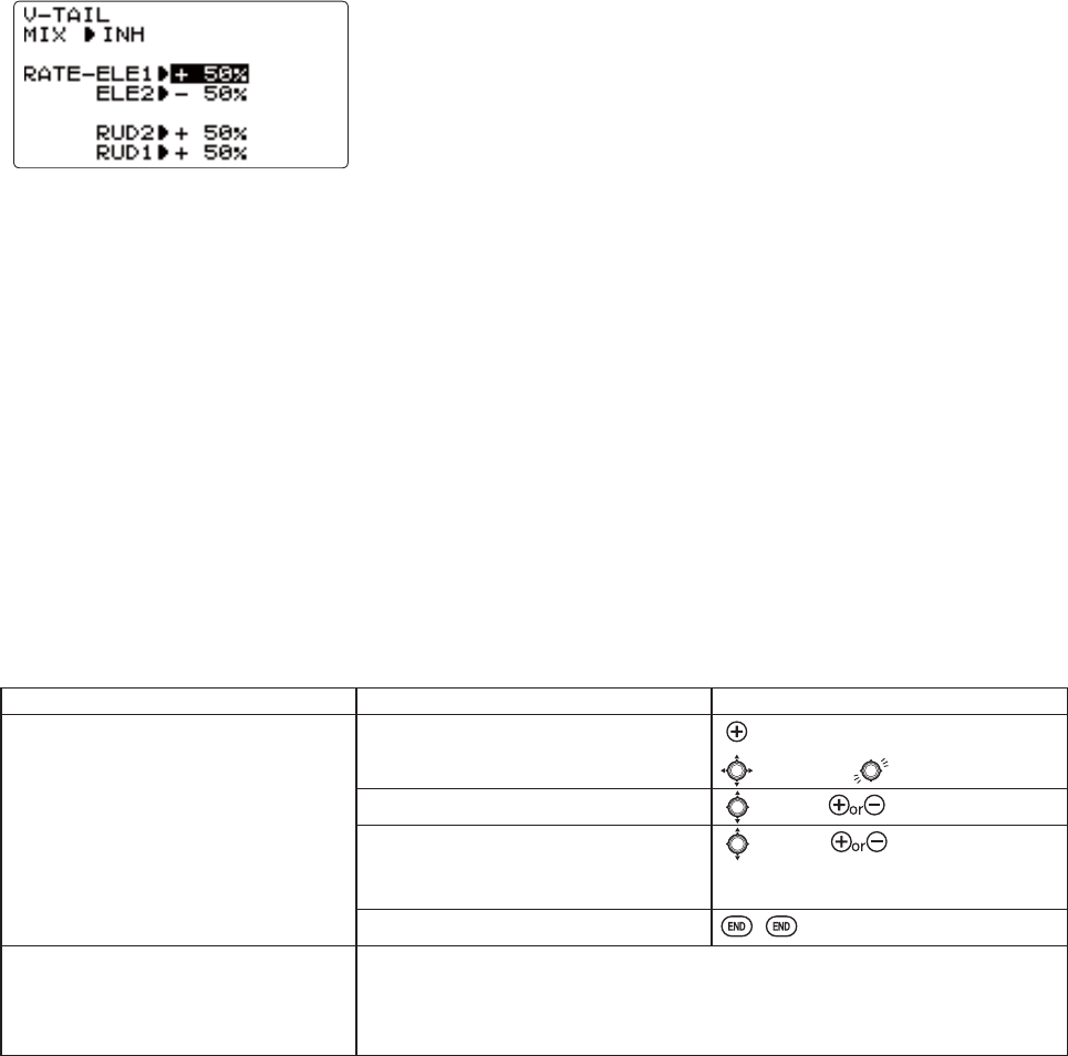
55
Using V-TAIL (ACRO):
V-TAILPL[LQJLVXVHGZLWKYWDLODLUFUDIWVRWKDWERWKHOHYDWRUDQGUXGGHU
functions are combined for the two tail surfaces. Both elevator and rudder travel
can be adjusted independently on each surface.
NOTE: If V-TAIL is active, you cannot activate ELEVON or AILEVATOR functions. If one of these functions is active, an error
message will be displayed and you must deactivate the last function prior to activating V-TAIL.
NOTE%H VXUHWR PRYH WKH HOHYDWRU DQGUXGGHU VWLFNVUHJXODUO\ ZKLOHFKHFNLQJ WKHVHUYR PRWLRQV ,I D ODUJHYDOXHRI
WUDYHOLVVSHFL¿HGZKHQWKHVWLFNVDUHPRYHGDWWKHVDPHWLPHWKHFRQWUROVPD\ELQGRUUXQRXWRIWUDYHO'HFUHDVHWKH
travel until no binding occurs.
Adjustability:
5HTXLUHVXVHRI&+DQG&+
,QGHSHQGHQWO\DGMXVWDEOHWUDYHOVDOORZIRUGLIIHUHQFHVLQVHUYRWUDYHOV
5XGGHU GLIIHUHQWLDO LV QRW DYDLODEOH 7R FUHDWH UXGGHU GLIIHUHQWLDO VHW RUD1 and 2 to 0. Next, use two programmable
mixes, RUD-ELE and RUD-RUD, setting different percentages for up and down. These are your new rudder travels. Trim off
DQGVZLWFKDVVLJQPHQWQXOOVR\RXFDQ¶WDFFLGHQWDOO\WXUQRIIUXGGHU6HHPROG.MIX, p. 65.)
)RUGHWDLOVRQVHWWLQJXSDFRPSOH[SODQHSOHDVHYLVLWRXU)$4DWZZZIXWDEDUFFRP?IDT?0DQ\RWKHUVHWXSH[DPSOHV
DUHDYDLODEOHDWWKLVORFDWLRQ
GOAL of EXAMPLE: STEPS: INPUTS:
Activate V-TAIL.
Adjust left elevator servo to 95% travel
WRPDWFKWRULJKWVHUYRVWUDYHO
Open the V-TAIL function. for 1 second.
to V-TAIL.
Activate the function. to MIX. to ACT.
optional: adjust the travels separately
IRUWKHVHUYRVDVHOHYDWRUV([VHW
left to 95%
to ELE1. to 95%.
Repeat as necessary for other servos.
Close menu.
Where next? Adjust END POINTs: see p. 36 and SUB-TRIMs: see p. 46.
Set up dual/triple rates and exponential(D/R,EXP): see p. 39.
Set up ELE-FLAP mix: see p. 59.
9LHZDGGLWLRQDOPRGHOVHWXSVRQWKHLQWHUQHWZZZIXWDEDUFFRP?IDT?
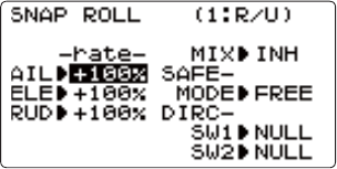
56
6QDS5ROOVDWWKHÀLFNRIDVZLWFKSNAP-ROLL) (ACRO):
7KLVIXQFWLRQDOORZV \RX WRH[HFXWHVQDS UROOV E\ÀLSSLQJD VZLWFK SURYLGLQJ
the same input every time. It also removes the need to change dual rates on the
3 channels prior to performing a snap, as SNAP-ROLLDOZD\VWDNHVWKHVHUYRVWR
the same position, regardless of dual rates, inputs held during the snap, etc.
1RWH(YHU\DLUFUDIWVQDSVGLIIHUHQWO\GXHWRLWV&*FRQWUROWKURZVPRPHQWVHWF6RPHPRGHOVVQDSZLWKRXWDLOHURQ
others snap on elevator alone. Most models snap most precisely with a combination of all 3 surfaces. Additionally, rate of
speed and acceleration when using the snap switch will affect how the model snaps.
Adjustability:
Travel: Adjust the amount of elevator, aileron and rudder travel automatically applied.
5DQJHWRRQDOOFKDQQHOV'HIDXOWLV100% of range of all 3 channels.
'LUHFWLRQV Up to 4 separate snaps may be set up, one for each of the 4 direction choices (up/right, down/right, up/left,
down/left). Each snap is fully adjustable regarding travels and direction on each of the 3 channels.
Note: IRU VLPSOLFLW\ WKH UDGLR UHIHUV WR VQDSV WKDW XVH ³83´ RU SRVLWLYH HOHYDWRU DV ³8´ RU ³83´ VQDSV 7KLV LV PRUH
FRPPRQO\UHIHUUHGWRDVDSRVLWLYHRULQVLGHVQDS³'´RU³'2:1´VQDSVDUHPRUHFRPPRQO\UHIHUUHGWRDVQHJDWLYHRU
outside snaps.
R/U = Right positive R/D = Right negative L/U = Left positive L/D = Left negative snap roll
$VVLJQPHQWRIWKHVZLWFKHVDIRC-SW1/2) to change snap directions is fully adjustable and optional. If you wish to have
only one snap, leave the switches as NULL. (If assigned, SW1 = up/down, SW2 = left/right.)
&DXWLRQLWLVFULWLFDOWKDW\RXUHPHPEHULI\RXDVVLJQHGVZLWFKHVWRVHOHFWWKHWKUHHDGGLWLRQDOVQDSV
)RUH[DPSOHDVVLJQ6:,7&+$IRU8'VQDSGLUHFWLRQDQGWKHQDOVRDVVLJQ6:,7&+$IRUHOHYDWRUGXDOUDWHV
:KLOH À\LQJ RQ HOHYDWRU ORZ UDWH 6:,7&+$ '2:1 \RX SXOO \RXU VQDS 6:,7&+ 7KH PRGHO ZLOO XVH WKH
WKURZVVHWLQWKHVQDSSURJUDPPLQJWKHORZUDWHHOHYDWRUKDVQRHIIHFWDQGEHDGRZQQHJDWLYHRXWVLGHVQDS
not an up (positive/inside) snap.
%RWKRIWKHVHPD\FRPHDVDJUHDWVXUSULVHDQGULVNFUDVKLQJLI\RXDUHXQSUHSDUHG
6DIHW\6ZLWFKSAFE-MODE): a safety may be set up on your landing gear SWITCH, preventing accidental snap rolls while
the landing gear is down. The safety switch is turned on and off with the landing gear SWITCH.
CH5+/CH5- WKH VDIHW\PHFKDQLVPLV DFWLYDWHGZKHQWKHODQGLQJ JHDU6:,7&+LVLQ WKHVDPHSRVLWLRQZKHQ
this feature is changed to ON position (CH5+ or CH5-). Snap rolls will not be commanded even if the snap roll
SWITCH is turned on with the gear SWITCH in this position. When the landing gear SWITCH is moved to the
opposite position, snap rolls may be commanded.
FREE: the safety mechanism is completely turned off. Snaps can be commanded regardless of the gear SWITCH
POSITION.
Note: The location of the safety switch always follows channel 5. If channel 5 is reassigned to switch C, for
example, switch C is now the safety. If channel 5 is nulled, the safety function will not be available.
7UDLQHU6DIHW\SNAP-ROLL is automatically disabled when the trainer function is activated.

57
GOAL of EXAMPLE: STEPS: INPUTS:
Activate SNAP-ROLL. Adjust aileron to
105%,elevator travel to 95%, rudder
travel to 120% in the right/up snap.
Activate SAFE-MODE so snaps cannot be
performed when gear is down.
Adjust rudder travel in the left/down
snap to 105%.
1RWHXVLQJQHJDWLYHSHUFHQWVFDQ
FKDQJHDQ\RIWKHVQDSGLUHFWLRQV)RU
H[DPSOHFKDQJHVQDSWRGRZQ E\
FKDQJLQJWKHHOHYDWRUSHUFHQWWR-100%
Open the SNAP-ROLL function. for 1 second.
to SNAP-ROLL.
Activate the function. to MIX. to OFF or ON.
Adjust the travels as needed. (Ex:
aileron to 105%, elevator to 95%, rudder
to 120%.)
to AIL. to 105%.
to ELE. to 95%.
to RUD. to 120%.
Optional: Activate SAFE-MODE>([21
when SWITCH E-$RUG-+
LVGRZQPHDQLQJVQDSIXQFWLRQLV
deactivated when that switch is in the
GRZQSRVLWLRQ@
E or G up. to SAFE-MODE
to CH-.
snap switch.
Notice MIX reading is still OFF.
E or G down.
Notice MIX reading changes to ON.
2SWLRQDO$VVLJQVZLWFKHVWRXSGRZQ
DQG OHIWULJKW ([ &KDQJH WR WKH OHIW
down snap and adjust rudder to 105%
to SW1. to SwA.
to SW2. to SwB.
SwA down SwB down.
Repeat steps above to set percentages.
Close menu.
Where next? Set up programmable mixes: see p. 65.
9LHZDGGLWLRQDOVHWXSVRQWKHLQWHUQHWZZZIXWDEDUFFRP?IDT?
58
MIXES: WKHEDFNERQHRIQHDUO\HYHU\IXQFWLRQ
Mixes are special programs within the radio that command one or more channels to act together with input from only one
VRXUFHVXFKDVDVWLFNVOLGHURUNQRE
There are a variety of types of mixes.
Types:
Linear:0RVWPL[HVDUHOLQHDU$OLQHDUPL[WHOOVWKHVODYHVHUYRWRGRH[DFWO\ZKDWWKHPDVWHUVHUYRLVGRLQJXVLQJ
RIWKHVODYHFKDQQHO¶VUDQJHWRGRVR$QH[DPSOHLVFLAPERON:KHQDLOHURQVWLFNLVPRYHGWKHÀDSVHUYRLVWROG
WRPRYHH[DFWO\WKHVDPHDPRXQW$OLQHDUPL[ZRXOGWHOOWKHVODYHVHUYRIRUH[DPSOHWRPRYHWRRILWVUDQJH
ZKHQWKHPDVWHU¶VFRQWUROLVPRYHGVHHS
Offset: An OFFSETPL[LVDVSHFLDOW\SHRIOLQHDUPL[:KHQWKHPL[LVWXUQHGRQXVXDOO\DÀLSRIDVZLWFKWKHVODYH
servo is moved to a set percentage of its range. An example of this is AIRBRAKEPRYLQJÀDSVÀDSHURQVDQGHOHYDWRUDOO
WRDVHWSRVLWLRQDWWKHÀLSRIDVZLWFK
Curve: Curve mixes are mostly used in helicopters, but may also be used in airplanes and gliders. An example is
THROTTLE-NEEDLE PL[LQJ ZKHUH WKH LQIOLJKW QHHGOH¶V VHUYR LV PRYHG FKDQJLQJ WKH PL[WXUH DV WKH WKURWWOH VHUYR LV
moved. (see p. 62.)
'HOD\'HOD\PL[HVDUHSDUWRIDIHZYHU\VSHFLDOIXQFWLRQVWKDWPDNHWKHVHUYRPRYHWRLWVGHVLUHGUDQJHPRUHVORZO\
THROTTLE DELAY (simulates turbine engines, p. 63) and the elevator delay in AIRBRAKE are two examples of this (see p. 61).
DELAY in HELI (see p. 84) is another example that slows the servo movement to the trim settings for the other conditions.
(VVHQWLDOO\HYHU\IHDWXUHLQWKHUDGLR¶VSURJUDPPLQJLVUHDOO\DPL[ZLWKDOODVVLJQPHQWVSURJUDPPLQJVHWXSDQGUHDG\
to use. Additionally, the 8J ACROSURJUDPVERWKSURYLGHOLQHDUDQGFXUYHIXOO\SURJUDPPDEOHPL[HVHELI provides 4
OLQHDUDQGFXUYHWKDWDOORZ\RXWRVHWXSVSHFLDOPL[HVWRUHVROYHÀLJKWGLI¿FXOWLHVDFWLYDWHDGGLWLRQDOIXQFWLRQVHWF
/HW¶VORRNTXLFNO\DWDIHZH[DPSOHVWKDWDUHIHDWXUHVZH¶YHDOUHDG\FRYHUHG7KLVPD\KHOSWRFODULI\WKHPL[W\SHVDQG
the importance of mixes.
$GGLWLRQDOH[DPSOHV
([SRQHQWLDOLVDSUHSURJUDPPHGFXUYHPL[WKDWPDNHVWKHVHUYRVUHVSRQVHPRUHRUOHVVVHQVLWLYHDURXQGFHQWHU
VWLFNZRUNVLQFRQMXQFWLRQZLWKGXDOUDWHDOLQHDUPL[WKDWDGMXVWVWKHWRWDOUDQJHVHHD/R,EXP, p. 39.
IDLE-DOWN and THR-CUT are two OFFSETSUHSURJUDPPHGPL[HV7KHVHWHOOWKHWKURWWOHVHUYRZKHQEHORZDFHUWDLQSRLQW
to move toward idle an additional set percentage to help close the carburetor.
ELE-TO-FLAP PL[LQJ LV D SUHSURJUDPPHG OLQHDU PL[ WR PRYH WKH ÀDSV SURSRUWLRQDOO\ WR HOHYDWRU FRQWURO KHOSLQJ WKH
model loop even tighter than it can on elevator alone. (see p. 59.)
THROTTLE-NEEDLEPL[LQJLVDFXUYHPL[OLNHPROG.MIX 5 to 6IRUSURSHULQÀLJKWQHHGOHVHWXSVHHS
THROTTLE DELAYPL[LQJLVDSUHSURJUDPPHGGHOD\PL[WKDWVORZVGRZQWKHUHVSRQVHRIWKH&+VHUYRVHHS
1H[W ZHOO JHW DQ LQGHSWK ORRN DW VRPH SUHSURJUDPPHG PL[HV PL[HV ZKRVH FKDQQHOV DUH SUHGH¿QHG E\ )XWDED IRU
VLPSOLFLW\DQGODVWORRNDWWKHIXOO\SURJUDPPDEOHPL[W\SHV
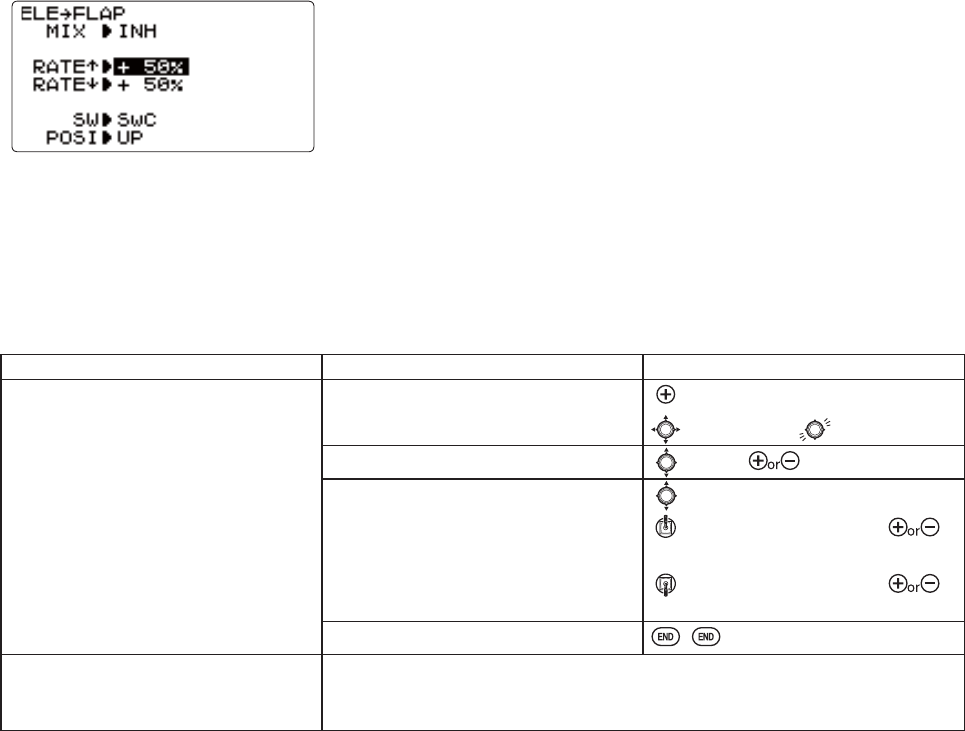
59
ELEV-FLAP mixing (ACRO):
ELEV-FLAPPL[LQJLVWKH¿UVWSUHSURJUDPPHGPL[ZHOOFRYHU7KLVPL[PDNHV
WKH ÀDSV GURS RU ULVH ZKHQHYHU WKH ELEVATOR STICK is moved. It is most
FRPPRQO\XVHGWRPDNHWLJKWHUS\ORQWXUQVRUVTXDUHUFRUQHUVLQPDQHXYHUV,Q
PRVWFDVHVWKHÀDSVGURRSDUHORZHUHGZKHQXSHOHYDWRULVFRPPDQGHG
Adjustability:
Rate IXOO XS ÀDS WR IXOO GRZQ ÀDS ZLWK D GHIDXOW RI
RQHKDOIRIWKHÀDSUDQJHLVDFKLHYHG when the ELEVATOR STICK is pulled
to provide full up elevator.)
6ZLWFK: fully assignable. (SwA to H)
,)\RXVHWLWWRNULLWKHPL[GRHVQRWZRUN
GOAL of EXAMPLE: STEPS: INPUTS:
Activate ELEV-FLAP mixing. Adjust flap
travel to 0%ÀDSVZLWKQHJDWLYHHOHYDWRU
(push) and 45% flaps with positive
elevator.
Open the ELEV-FLAP function. for 1 second.
to ELEV-FLAP.
Activate the function. to MIX. to ACT.
Adjust the travels as needed.
(Ex: 0%,to 45%.)
to RATE.
ELEVATOR STICK.to
0%.
ELEVATOR STICK.to
45%.
Close menu.
Where next? $GMXVWÀDSHURQVÀDSWUDYHODYDLODEOHFLAPERON): see p. 50.
Set up AIRBRAKEFURZEXWWHUÀ\VHHS
9LHZDGGLWLRQDOVHWXSVRQWKHLQWHUQHWZZZIXWDEDUFFRP?IDT?
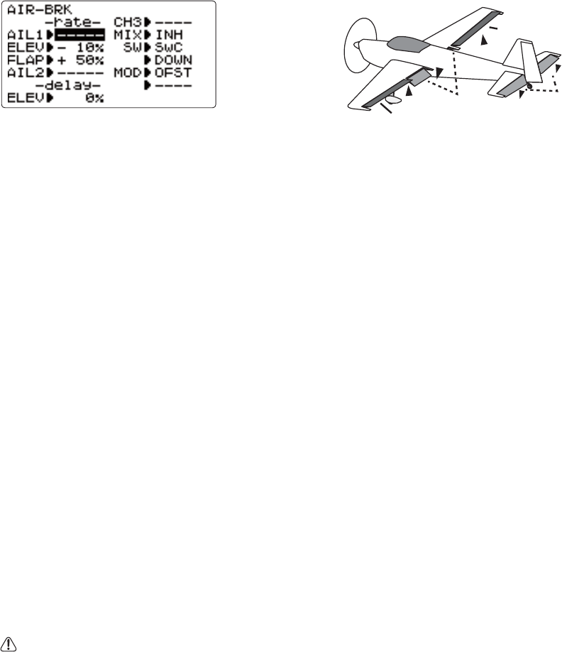
60
AIRBRAKE mixing (ACRO):
/LNHFLAPERON and AILEVATOR,AIRBRAKELVRQHIXQFWLRQWKDWLVUHDOO\PDGHXSRIDVHULHVRISUHSURJUDPPHGPL[HVDOO
done for you within the radio. AIRBRAKE VLPXOWDQHRXVO\ PRYHV WKH ÀDSV LI LQVWDOOHG WZLQ DLOHURQV LI LQVWDOOHG DQG
HOHYDWRUVDQGLVXVXDOO\XVHGWRPDNHVWHHSGHVFHQWVRUWROLPLWLQFUHDVHVLQDLUVSHHGLQGLYHV
7KLVIXQFWLRQLVRIWHQXVHGHYHQRQPRGHOVZLWKRXWÀDSVDVDQHDV\ZD\WRXVHWKHÀDSHURQVDQGFLAP-ELEVATOR mixing
together.
Adjustability:
Activation: Proportional by moving the THROTTLE STICKRUVHWSRVLWLRQVE\ÀLSSLQJWKHDVVLJQHGVZLWFK
6ZLWFK Mix SWITCH is selectable.
LINR(Linear/Inversely proportional to THROTTLE STICK): provides a proportional increase in amount of AIRBRAKE
action as THROTTLE STICK is lowered and assigned switch is on. Provides gradually more AIRBRAKE as you slow
WKH HQJLQH ,QFOXGHV VHOHFWDEOH VWLFN SRVLWLRQ ZKHUH AIRBRAKE begins, gradually increasing to the same setting as the
THROTTLE STICK is lowered.
OFST(Offset): Provides AIRBRAKEUHVSRQVHLPPHGLDWHO\XSRQVZLWFKPRYHPHQWJRLQJWRDSUHVHWWUDYHORQHDFKDFWLYH
FKDQQHOZLWKRXWDQ\PHDQVRILQÀLJKWDGMXVWPHQW
'HOD\HGUHDFWLRQ<RXFDQVXSSUHVVVXGGHQFKDQJHVLQ\RXUPRGHOVDWWLWXGHZKHQAIRBRAKE is activated by setting the
delay (delay-ELEVLWHPWRVORZGRZQWKHHOHYDWRUUHVSRQVHDOORZLQJWKHÀDSVDLOHURQVHOHYDWRUWRDOOUHDFKWKHLUGHVLUHG
end point together.
Channels controlled(OHYDWRUVWZLQDLOHURQVDQGÀDSVPD\EHVHWLQGHSHQGHQWO\LQAIRBRAKE, including set to 0 to
have no effect.
7ZLQDLOHURQVHUYRV,IFLAPERON,ELEVON and AIL-DIFF functions are inhibited, then AIL1 and AIL2 settings will have no
effect.
,IFLAPERONLVDFWLYHWKHWUDYHORIWKHDLOHURQVFDQEHLQGHSHQGHQWO\DGMXVWHGIRUWKHVHUYRVSOXJJHGLQWR&+DQG
&+7KHÀDSFKRLFHKDVQRHIIHFWRQWKHÀDSHURQV
,IAIL-DIFFLVDFWLYHWKHQ&+DQG&+PD\EHLQGHSHQGHQWO\DGMXVWHG
1RUPDOO\ ERWK DLOHURQV DUH UDLVHG HTXDOO\LQ AIRBRAKE, and the elevator motion is set to maintain trim when
the ailerons rise. Different amounts may be set for each aileron to correct for torque reactions and other unique
characteristics of the model.
Be sure you understand what dropping ailerons will do when in AIRBRAKE. Along with creating an enormous amount
RIGUDJGHVLUDEOHIRUVSRWODQGLQJVWKLVDOVRFUHDWHVZDVKLQDKLJKHUDQJOHRIDWWDFNZKHUHWKHDLOHURQVDUHDQG
encourages tip stalling. If you are using this for aerobatic performance and not "sudden stops", consider raising the
DLOHURQVDQGGURSSLQJWKHÀDSVLQVWHDGDVVKRZQLQWKHGLDJUDPDERYH
Twin elevator servos:
,IAILEVATOR is active, the AIL1 and AIL2 settings still only affect FLAPERON or AIL-DIFF servos, NOT the elevator servos.
(they would have the AIL3 and AIL4 settings.)
AIL1
AIL2 FLP ELE
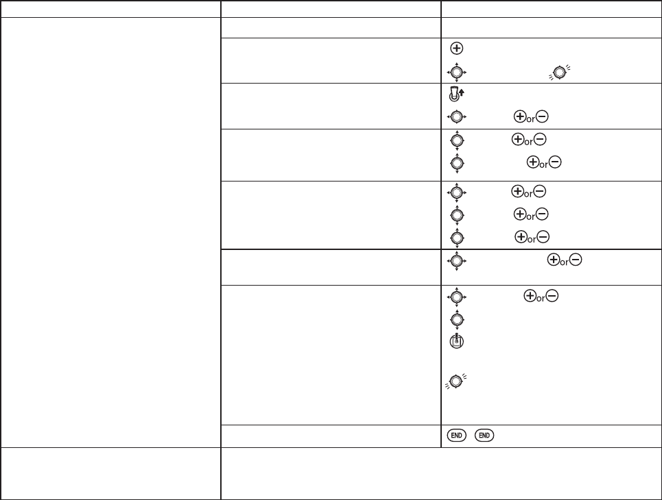
61
GOAL of EXAMPLE: STEPS: INPUTS:
Activate AIRBRAKE on a FLAPERON.
model. Adjust the flaperon travel to
75%,with negative elevator (push) of
25%.
&RQ¿UPFLAPERON is active. see FLAPERON instructions.
Open the AIRBRAKE function. for 1 second.
to AIRBRAKE.
Activate the function. Switch C in up position.
to MIX. to OFF.
SW selection.
A position is turned ON by down with a
center.
to SW. to SWC.
to DOWN. to CT&DN.
Adjust the travels as needed.
(Ex:Ailerons each 75%, Elevator -25%.)
to AIL1. to 75%.
to ELEV. to -25%.
to FLAP. to 75%.
2SWLRQDOGHOD\KRZTXLFNO\WKH
elevator servo responds.
WRGHOD\ELEV. to 25%.
Optional: change the mixing from full
amount upon switch to proportional to
the THROTTLE STICKV SUR[LPLW\ WR
idle.
to MODE. to LINR (0%).
to 0%.
THROTTLE STICK to desired
point.
for 1 sec, until beeps
(display changes if new setting is different from prior
setting).
Close menu.
Where next? $GMXVWÀDSHURQVWRWDOÀDSWUDYHODYDLODEOHFLAPERON): see p. 50.
Set up ELE-FLAP mixing: see p. 59.
9LHZDGGLWLRQDOPRGHOVHWXSVRQWKHLQWHUQHWZZZIXWDEDUFFRP?IDT?
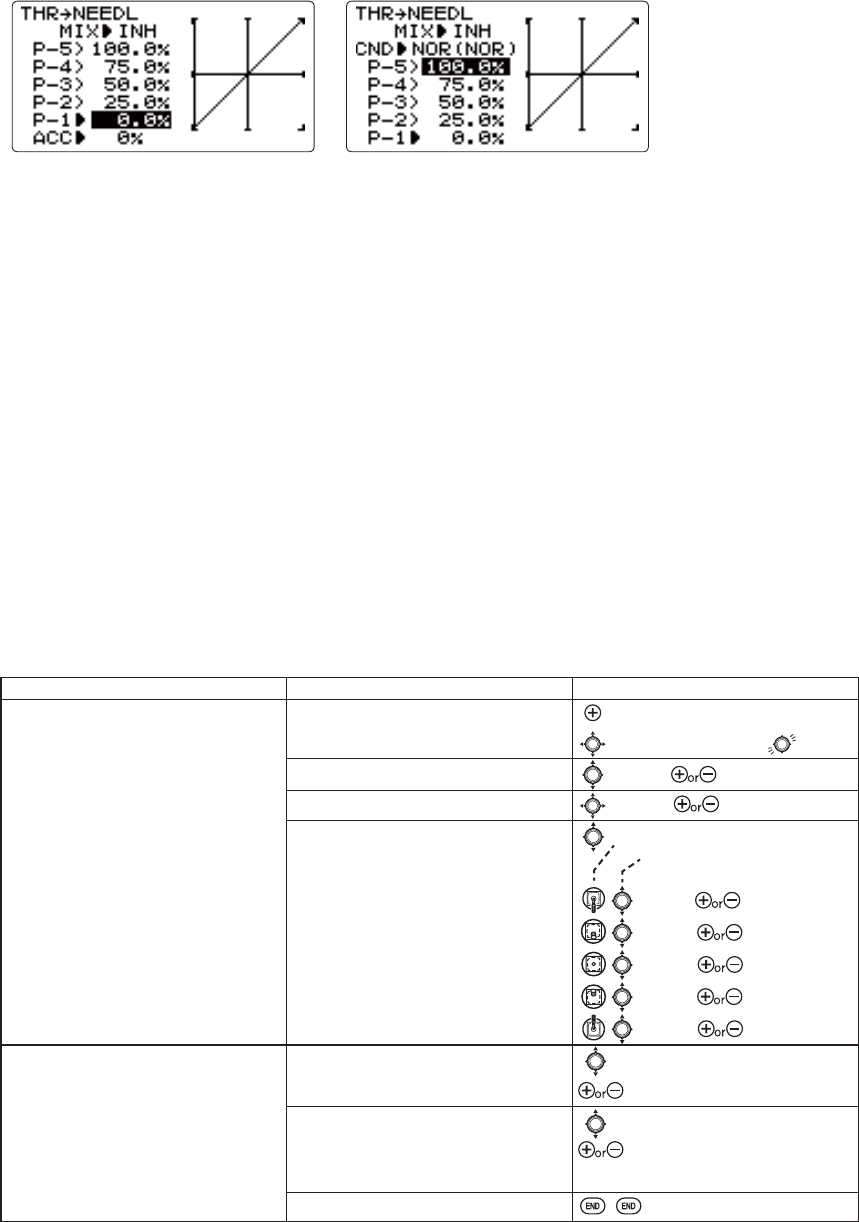
62
THROTTLE-NEEDLE mixing (ACRO/HELI):
THROTTLE-NEEDLELVDSUHSURJUDPPHGPL[WKDWDXWRPDWLFDOO\PRYHVDQLQÀLJKWPL[WXUHVHUYR&+LQUHVSRQVHWRWKH
THROTTLE STICK inputs for perfect engine tuning at all throttle settings. This function is particularly popular with
FRQWHVW SLORWV ZKR À\ LQ D ODUJH YDULHW\ RI ORFDWLRQV QHHGLQJ UHJXODU HQJLQH WXQLQJ DGMXVWPHQWV DQG UHTXLULQJ SHUIHFW
HQJLQHUHVSRQVHDWDOOWLPHVDQGLQDOOPDQHXYHUV$OVRSRSXODUWRPLQLPL]HÀRRGLQJDWLGOHRILQYHUWHGHQJLQHLQVWDOODWLRQV
RULQVWDOODWLRQVZLWKDKLJKWDQNSRVLWLRQ1RWQHHGHGIRUIXHOLQMHFWLRQHQJLQHVZKLFKGRWKLVDXWRPDWLFDOO\
Adjustability:
)LYHSRLQWFXUYHDOORZVDGMXVWPHQWRIHQJLQHPL[WXUHDWYDULHGWKURWWOHVHWWLQJV
7KHLQÀLJKWPL[WXUHVHUYRPXVWFRQQHFWWRUHFHLYHU&+
7KURWWOHFXWIHDWXUHDOVRPRYHVWKHLQÀLJKWQHHGOHVHUYR
%HFDXVHERWKXVH&+WKLVIXQFWLRQFDQQRWEHXVHGVLPXOWDQHRXVO\ZLWKAILEVATOR.
$QDFFHOHUDWLRQACC) function (ACRO only) helps the engine compensate for sudden, large amounts of throttle input by
PDNLQJWKHPL[WXUHVXGGHQO\ULFKHUWKHQHDVLQJLWEDFNWRWKHSURSHUDGMXVWPHQWIRUWKDWWKURWWOHVHWWLQJ7KLVIXQFWLRQ
UHTXLUHVVRPHDGMXVWPHQWWREHVW¿W\RXUHQJLQHDQG\RXUÀ\LQJVW\OH$GMXVWHQJLQH¶VUHVSRQVHXQWLOQRKHVLWDWLRQRFFXUV
on rapid throttle input.
6HSDUDWHFXUYHVDUHDYDLODEOHHELIRQO\IRUQRUPDOLGOHXSVDQGFRPELQHGDQGLGOHXS,PPHGLDWHO\EHORZMIX
WKHUDGLRGLVSOD\VWKHFXUYH\RXDUHHGLWLQJH[>NORDQGWKHQZKLFKFRQGLWLRQLVFXUUHQWO\DFWLYHE\\RXUVZLWFKHVH[
(ID1/2). Note that you can edit the mix for a different condition without being in that condition, to allow editing without
KDYLQJWRVKXWRIIWKHKHOLFRSWHU¶VHQJLQHHYHU\WLPH%HVXUH\RXDUHHGLWLQJWKHSURSHUFXUYHE\FKHFNLQJWKHQDPHDIWHU
the > and not the one in parentheses.
GOAL of EXAMPLE: STEPS: INPUTS:
Activate THROTTLE-NEEDLE mixing.
Adjust the points as follows to resolve
a slight lean midrange problem:
1: 40%
2: 45%
3: 65%
4: 55%
5: 40%
Open the THROTTLE-NEEDLE function. for 1 second.
to THROTTLE-NEEDLE.
Activate the function. to MIX. to ACT.
HELI only. Select the condition to edit. to CND.to NOR or (I12/ID3]
Adjust the travels as needed to match
\RXUHQJLQHE\VORZO\PRYLQJWKHVWLFN
to each of the 5 points, then adjusting
the percentage at that point until the
engine is properly tuned. to P-1. to 40%.
to P-2. to 45%.
to P-3. to 65%.
to P-4. to 55%.
to P-5. to 40%.
ACRO RQO\2SWLRQDOLQFUHDVH PL[WXUH
ZKHQWKURWWOHLVDSSOLHGUDSLGO\ACC
to ACC.
as needed.
HELI only: set curves for other
conditions.
to condition name.
to next condition to edit.
Repeat above steps as needed.
Close menu.
(HELI)(ACRO)
ACROFXUVRUPRYHPHQWDWTHR Stick
HELIFXUVRUPRYHPHQWDWJOG KEY
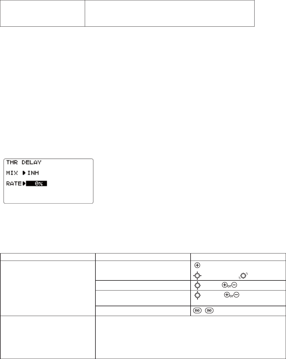
63
Throttle delay function THR-DELAY (ACRO):
The THR-DELAY function is used to slow the response of the throttle servo to
simulate the slow response of a turbine engine. A 40% delay setting corresponds
WRDERXW D RQHVHFRQGGHOD\ ZKLOH D100% GHOD\WDNHV DERXW HLJKWVHFRQGV WR
UHVSRQG)RUKHOLFRSWHUVVHHDELAYS, p. 84.
7KLV IXQFWLRQ PD\ DOVR EH XVHG WR FUHDWH D ³VORZHG VHUYR´ RQ D FKDQQHO RWKHU WKDQ WKURWWOH 7KLV LV DFFRPSOLVKHG E\
SOXJJLQJWKHGHVLUHGVHUYR([JHDUGRRUVLQWR&+THR), throttle into an auxiliary channel such as 8, and then using
VRPHFUHDWLYHPL[HV3OHDVHVHHRXU)UHTXHQWO\$VNHG4XHVWLRQVDUHDDWZZZIXWDEDUFFRP?IDT?IRUWKLVVSHFL¿FH[DPSOH
GOAL of EXAMPLE: STEPS: INPUTS:
Activate THR-DELAYIRUDGXFWHGIDQ
UHSOLFDRIDWXUELQHSRZHUHGDLUFUDIW
Slow the servo response by one second.
Open the THR-DELAY function. for 1 second.
to THR-DELAY.
Activate the function. to MIX. to ACT.
Adjust the RATE to match the desired
servo speed. (Ex: 40%.)
to RATE. to 40%.
Close menu.
Where next? Set up THROTTLE-NEEDLE mixing: see p. 62.
$GMXVWWKURWWOH¶VEND POINT: see p. 36.
Adjust throttle exponential (D/R,EXP): see p. 39.
Set up AILEVATOR: see p. 54.
Set up programmable mixes, for example, RUDDER-AILERON: see p. 65.
9LHZDGGLWLRQDOPRGHOVHWXSVRQWKHLQWHUQHWZZZIXWDEDUFFRP?IDT?
Where next? Set up THROTTLE DELAYWRLPLWDWHDMHWHQJLQH¶VODJVHHS
Adjust throttle and Ch8 END POINTs: see p. 36.
Set up programmable mixes, for example, AILERON-to-RUDDER: see p. 65.
9LHZDGGLWLRQDOPRGHOVHWXSVRQWKHZZZIXWDEDUFFRP?IDT?
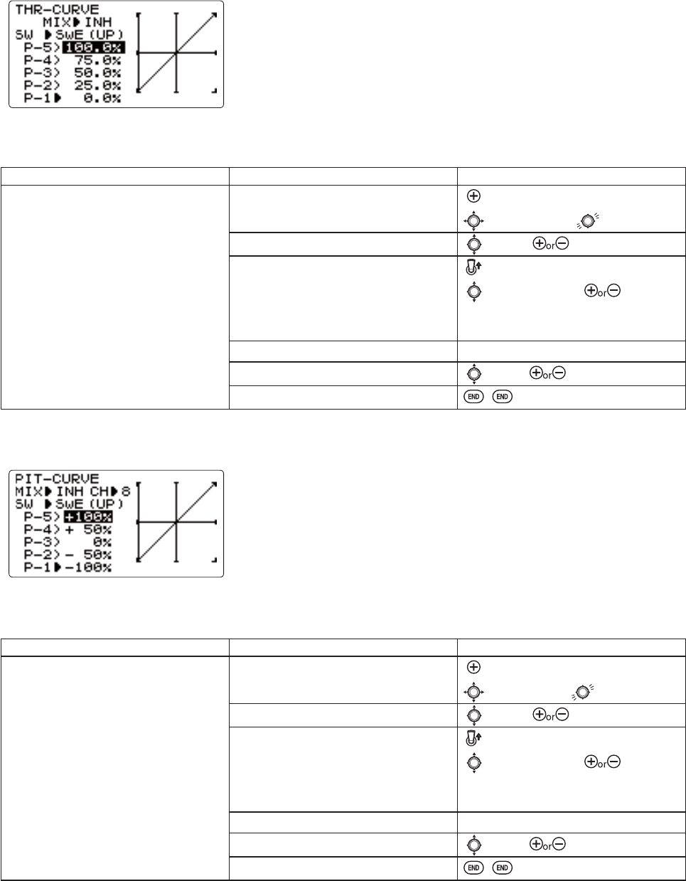
64
Throttle curve (THR-CURVE)(ACRO):
Pit curve (PIT-CURVE)(ACRO):
This function adjusts the throttle operation curve for optimum engine response
WRWKURWWOHVWLFNPRYHPHQW
NOTE: If the throttle EXP function is activated, you cannot use THR-CURVE
function simultaneously.
This function is an object for the variable pitch propellers of an airplane.
7KHFXUYHRI¿YHSRLQWVFDQEHVHWXS
127(&+RIDSLWFKFDQEHVHWWR&+RU&+
Adjustability:
6HSDUDWHFXUYHVIRUHDFKSRVLWLRQDUHDYDLODEOH
GOAL of EXAMPLE: STEPS: INPUTS:
Adjust throttle curve until engine idles
reliably.
Open the THR-CURVE function. for 1 second.
to THR-CURVE.
Activate the function. to MIX. to ON.
$GMXVWWKHSRLQWIRUHDFKVZLWFK
position.
Switch E in up position.
to point 1 (P-1). to desired
throttle servo position.
Repeat above steps.
Adjust the next switch position. Repeat above steps.
2SWLRQDO$VVLJQWKHVZLWFK to SW. to desired switch.
Close.
Adjustability:
6HSDUDWHFXUYHVIRUHDFKSRVLWLRQDUHDYDLODEOH
GOAL of EXAMPLE: STEPS: INPUTS:
Adjust pit curve until engine idles . Open the PIT-CURVE function. for 1 second.
to PIT-CURVE.
Activate the function. to MIX. to ON.
$GMXVWWKHSRLQWIRUHDFKVZLWFK
position.
Switch E in up position.
to point 1 (P-1). to desired
Pit position.
Repeat above steps.
Adjust the next switch position. Repeat above steps.
2SWLRQDO$VVLJQWKHVZLWFK to SW. to desired switch.
Close.
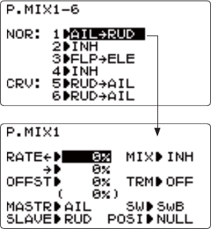
65
LINEAR PROGRAMMABLE MIXES (PROG.MIX1-4):
6DPSOHUHDVRQVWRXVHOLQHDUSURJUDPPDEOHPL[HV
7RFRUUHFWEDGWHQGHQFLHVRIWKHDLUFUDIWVXFKDVUROOLQJLQUHVSRQVHWRUXGGHULQSXW
7RRSHUDWHRUPRUHVHUYRVIRUDVLQJOHD[LVVXFKDVWZRUXGGHUVHUYRV
7RDXWRPDWLFDOO\FRUUHFWIRUDSDUWLFXODUDFWLRQVXFKDVORZHULQJHOHYDWRUZKHQÀDSVDUHORZHUHG
7RRSHUDWHDVHFRQGFKDQQHOLQUHVSRQVHWRPRYHPHQWLQD¿UVWFKDQQHOVXFKDVLQFUHDVLQJWKHDPRXQWRIVPRNHRLOLQ
UHVSRQVHWRPRUHWKURWWOHDSSOLFDWLRQEXWRQO\ZKHQWKHVPRNHVZLWFKLVDFWLYH
7RWXUQRIIUHVSRQVHRIDSULPDU\FRQWUROLQFHUWDLQFLUFXPVWDQFHVVXFKDVVLPXODWLQJRQHHQJLQHÀDPLQJRXWRQDWZLQ
RUWKURWWOHDVVLVWHGUXGGHUWXUQVDOVRZLWKDWZLQ
Adjustability:
'HIDXOWV7KHSURJUDPPDEOHPL[HVGHIDXOWWRWKHPRVWIUHTXHQWO\XVHGPL[HVIRUVLPSOLFLW\,I\RXZDQWWRXVHRQHRI
these mixes, simply select that mix number so that the master and slave servos are already selected for you.
PROG.MIX1DLOHURQWRUXGGHUIRUFRRUGLQDWHGWXUQV
PROG.MIX2HOHYDWRUWRÀDSIRUWLJKWHUORRSVHELIPL[HVGHIDXOWWRHOHYWRSLWFK
PROG.MIX3ÀDSWRHOHYDWRUWRFRPSHQVDWHSLWFKLQJZLWKÀDSVHELIPL[HVGHIDXOWWRSLWFKWRHOHY
PROG.MIX4WKURWWOHWRUXGGHUJURXQGKDQGOLQJFRPSHQVDWLRQ
&KDQQHOVDYDLODEOHWRPL[$OOIRXUPL[HVPD\XVHDQ\FRPELQDWLRQRI&+2IIVHWDQGGLDOLQFOXGH'7'7PD\
also be set to the master channels. (see below.)
0DVWHUthe controlling channel. The channel whose movement is followed by the slave channel.
Another channel: 0RVWPL[HVIROORZDFRQWUROFKDQQHO([UXGGHUWRDLOHURQVQRVZLWFKFRUUHFWVUROO
coupling.)
MASTER 6/$9( TRIM 6:,7&+ POSITION RATE 2))6(7
RUDD AIL OFF ANY NULL 25% 0
2IIVHWDVPDVWHUTo create an OFFSETPL[VHWWKHPDVWHUDV2)6([PRYHÀDSHURQVDVÀDSVRIWKHLUWRWDOWKURZ
when SWITCH C is in down position.)
MASTER 6/$9( TRIM 6:,7&+ POSITION RATE 2))6(7
OFS FLP N/A C DOWN 20% N/A
'LDODVPDVWHU7RGLUHFWO\DIIHFWRQHVHUYR¶VSRVLWLRQE\PRYLQJDGLDOVHWWKHPDVWHUDVWKHGHVLUHGGLDO
(Ex: create a second throttle trim on DT6 lever.)
MASTER 6/$9( TRIM 6:,7&+ POSITION RATE 2))6(7
DT6 THR N/A ANY NULL 5% N/A
6ODYH the controlled channel. The channel that is moved automatically in response to the movement of the master
FKDQQHO7KHVHFRQGFKDQQHOLQDPL[¶VQDPHLHDLOHURQWRUXGGHU
7ULPPDVWHU¶VWULPDIIHFWVVODYH1RWGLVSOD\HGLIPDVWHULVQRW&+EHFDXVHKDYHQRWULP([WZRUXGGHUVHUYRV
With TRIM OFF, rudder trim would bind the two servos. TRIM ON resolves this.
Your 8J contains four separate linear programmable mixes. (Note that P.Mixing
PL[LQJUDWHVDUHVHWZLWKDSRLQWFXUYH6HH&859(0,;(6
There are a variety of reasons you might want to use these mixes. A few are
OLVWHGKHUH$OORIWKHDGMXVWDEOHSDUDPHWHUVDUHOLVWHGEHORZEXWGRQ¶WOHWWKHP
VFDUH\RX)RU\RXU¿UVWIHZWLPHVH[SHULPHQWLQJZLWKPL[HVMXVWWXUQRQWKH
GHIDXOWPL[HV DGMXVW WKHPKRZ \RX WKLQNWKH\ QHHG WREH WKHQ XVH WKH VHUYR
VFUHHQ WR FKHFN DQG VHH LI \RX ZHUH FRUUHFW$V ZLWK DOO IXQFWLRQV D VDPSOH
setup follows, step by step, to assist you.
66
On/off choices:
SWITCH: Any of the positions of any of the 8 switches may be used to activate a mix. UP&CT,CT&DN options allow
the mix to be ONLQRIWKHSRVLWLRQVRIDSRVLWLRQSWITCH.
NULL: No SWITCH can turn this mix OFF. This mix is active at all times.
THR: Turned on/off by THROTTLE STICK movement. Trigger point/direction are selectable. Ex: OFSWRJHDUGRRUV
mix to open gear doors at idle, which is only active if throttle is below half.
MASTER 6/$9( TRIM 6:,7&+ POSITION RATE 2))6(7
OFS AU2 N/A THR Stick at 1/2,
for 1 sec.
100% N/A
Rate:WKHSHUFHQWDJHRIWKHVODYH¶VUDQJHLWZLOOPRYHXSRQPD[LPXPLQSXWIURPWKHPDVWHUFKDQQHO([RUDDER
AILERONPL[:KHQUXGGHULVPRYHGIXOOULJKWDLOHURQVPRYH´
MASTER 6/$9( TRIM 6:,7&+ POSITION RATE 2))6(7
RUD AIL OFF ANY NULL 50% 0
Offset:2IIVHWVWKHVODYH¶VFHQWHUUHODWLYHWRWKHPDVWHU([6PRNHYDOYHRSHQVZLGHUSHUWKURWWOHVHUYRSRVLWLRQZKHQ
VPRNHSWITCH is ON6PRNHVHUYR¶VQHXWUDOLVPRYHGGRZQIURPTHROTTLE STICK center to the bottom.
MASTER 6/$9( TRIM 6:,7&+ POSITION RATE 2))6(7
THR AU2 OFF E DOWN 100% 100%
67
GOAL of EXAMPLE: STEPS: INPUTS:
Set up a FLAP-ELEV mix:
ON when SWITCH C is in the down
position.
1RHOHYDWRUPRYHPHQWZKHQÀDSVPRYH
up (spoilers),
HOHYDWRUPRYHPHQWZKHQIODSV
move down,
)ODSKDV QRWULP OHYHU VR TRIM is not
DQRSWLRQ
Open an unused programmable mix.
(Ex: use P.MIX3VLQFHLWLVDOUHDG\VHWXS
for FLAP-ELEVATOR.)
for 1 second.
to P.MIX1-6.
to 3
Activate the function. to MIX. to ON.
Choose master and slave channels.
(Ex: no need to change MASTER/SLAVE.)
already FLP
already ELE
2SWLRQDOVHW0DVWHUDVOFS, DT5, DT6 or
VR6HHDERYHIRUGHWDLOV
to MASTER. to desired
choice.
Set TRIM as needed.
(Ex: leave TRIM not available.)
Assign SWITCH and position.
(Ex: change to C,DOWN.)
to SW. to C.
to POSI. to DOWN.
Optional: set switch to THR to activate
PL[ZLWKTHROTTLE STICK6HH
DERYHIRUGHWDLOV
to SW. to THR.
to POSI.
THROTTLE STICK to desired
point.
for 1 second to set.
Optional: set switch position to NULL
0DNHVPL[DFWLYHDWDOOWLPHV1RW
FRPSDWLEOHZLWKTHR
to POSI. to NULL.
Set rates. (Ex: Lo=0%+L 5%.) to RATE.
VR past center. Leave at 0%.
VR past center. to 5%.
Set OFFST, if needed. (Ex: 0.) to OFFST. Leave at 0%.
Close menu.
Where next? Adjust servo END POINTs: see p. 36.
Setup dual/triple rates and exponential (D/R,EXP): see p. 39.
Set up additional programmable mixes, ex: RUDDERAILERON: see p. 65.
9LHZQXPHURXVDGGLWLRQDOPL[VHWXSVZZZIXWDEDUFFRP?IDT?
2WKHU([DPSOHV
RUD-ELEV (ACRO) mix: Compensate for pitching up or down when rudder is applied.
AIL-RUD (ACRO): Coordinate turns by applying rudder automatically with aileron input. All model types.
ELEV-PIT (HELI) mix: compensate for the loss of lift of tilting the model.
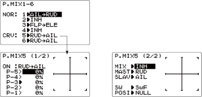
68
CURVE PROGRAMMABLE MIXES (PROG.MIX5-6):
<RXU-¶VACRO/HELI programs contain two separate curve programmable mixes. There are a variety of reasons you might
ZDQWFXUYH PL[HV IRU H[DPSOH ZKHQD OLQHDUPL[ GRHVQ¶W¿W \RXU QHHGV DORQJWKH ZKROH UDQJH 2QH SUHSURJUDPPHG
curve mix is the THROTTLE-NEEDLEIXQFWLRQ7KLVFXUYHLVDGMXVWDEOHDWSRLQWVDOORZLQJ\RXWRDGMXVWWKHPRWRU¶VWXQLQJ
at 5 points along its RPM range.
One programmable curve mix defaults to RUDDER-AILERON$OLQHDUPL[WKDWNHHSVWKHPRGHOIURPUROOLQJLQNQLIHHGJHLV
SUREDEO\WRRPXFKDLOHURQZKHQUXGGHULVDSSOLHGLQOHYHOÀLJKW&UHDWHDFXUYHPL[DQGVHWDOOSRLQWVWRPDWFKWKHOLQHDU
PL[,QKLELWWKHOLQHDUPL[WKHQDGMXVWWKHFXUYHWRJHWWKHULJKWUHVSRQVHDOODORQJWKHUXGGHUFKDQQHO¶VWUDYHO
$GMXVWDELOLW\IRUGHWDLOHGGH¿QLWLRQVVHH/LQHDU3URJUDPPDEOH0L[HVDQG*ORVVDU\
ACRO 'HIDXOWV The 2 programmable curve mixes default to the most frequent choices, but can be set to any channel.
P.MIX5UXGGHUWRDLOHURQIRUUROOFRXSOLQJFRPSHQVDWLRQ
P.MIX6UXGGHUWRDLOHURQIRUUROOFRXSOLQJFRPSHQVDWLRQ
HELI 'HIDXOWV
P.MIX5DLOHURQWRHOHYDWRUIRUFRRUGLQDWHGWXUQV
P.MIX6DLOHURQWRHOHYDWRUIRUFRRUGLQDWHGWXUQV
0DVWHUThe controlling channel can only be a channel. Cannot be OFFSET or dial.
7ULPnot available in curve mixes.
Offset: not available in curve mixes.
69
GOAL of EXAMPLE: STEPS: INPUTS:
Set up a RUDD-ELEV curve mix on a
model that pitches down severely at
full rudder and not at all with minimal
rudder input, and pitches worse on right
rudder than left:
P-1: 25%
P-2: 8%
P-3: 0%
P-4: 10%
P-5: 28%
ON when SWITCH C is down.
1RWHWKDWSRLQWLV2WKHUZLVHWKH
elevator would be retrimmed when the
mix is active and no rudder input is
given.)
Open an unused curve programmable
mix. (Ex: use PROG.MIX6 since it is
DOUHDG\VHWXSIRURUDDER-ELEV.)
for 1 second.
to P.MIX1-6.
to 6.
Activate the function. to MIX. to ON.
Choose master and slave channels.
(Ex: do not change MAS or SLV).
already RUDD
already ELEV
Assign SWITCH and position.
(Ex: change to C,DOWN.)
to SW. to C.
to POSI. to DOWN.
Optional: set switch to THR to activate
mix with THROTTLE STICK. (See
above for details.)
to SW. to THR.
to POSI.
THROTTLE STICK to desired
point.
for 1 second to set.
Optional: set switch position to NULL
0DNHVPL[DFWLYHDWDOOWLPHV1RW
FRPSDWLEOHZLWKTHR
to POSI. to NULL.
6HW GHVLUHG SHUFHQW DW WKH VWLFN SRLQWV
(Ex: listed at left.)
to P-1. to 25%.
5HSHDWIRUSRLQWV
Close menu.
Where next? Adjust servo END POINTs: see p. 36.
Set up AILEVATOR: see p. 54.
9LHZQXPHURXVPL[VHWXSVZZZIXWDEDUFFRP?IDT?
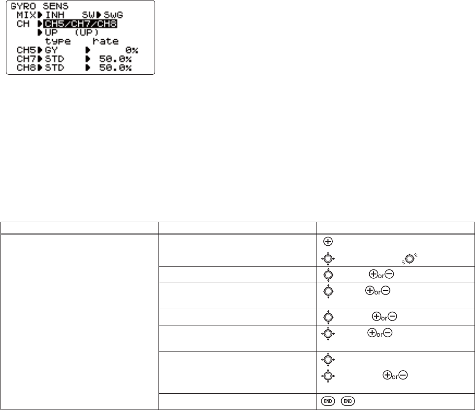
70
GYA gyro mixing
*<$VHULHVJ\URV
*<$ VHULHV J\URV DUH D KLJK SHUIRUPDQFH FRPSDFW DQG OLJKW ZHLJKW$9&6 J\URV GHYHORSHG IRU PRGHO DLUSODQHV$Q
LQWHJUDWHGVHQVRUDQGFRQWUROFLUFXLWPDNHWKHPHDV\WRPRXQW
*<$IRUDLUSODQHDLOHURQHOHYDWRURUUXGGHU
*<$IRUDLUSODQHDLOHURQVHVSHFLDOO\WZRVHUYRVVXFKDVZKHQXVLQJFLAPERON.
*<$IRUDLUSODQHDLOHURQHOHYDWRURUUXGGHUFRQWURO7ZRRIWKHVHVXUIDFHVD[LVFDQEHFRQWUROOHGE\*<$
*<$VHULHVJ\URRSHUDWLRQPRGHV
7KH*<$J\URVKDYHWZRRSHUDWLRQVPRGHV$9&6PRGHDQG1RUPDOPRGH
1RUPDO PRGH 7KLV PRGH SHUIRUPV JHQHUDO SURSRUWLRQDO FRQWURO RSHUDWLRQ )RU LQVWDQFH LW FRQWUROV WKH J\UR VR WKDW
FKDQJHVDUHFRXQWHUHGZKHQWKHDWWLWXGHRIWKHDLUFUDIWLVFKDQJHGE\FURVVZLQGHWF
$9&6 PRGH7KLVPRGH SHUIRUPV ERWK SURSRUWLRQDO DQGLQWHJUDWHG FRQWURO RSHUDWLRQ7KHGLIIHUHQFHEHWZHHQ 1RUPDO
PRGHDQG$9&6PRGHRSHUDWLRQ LV WKDWZKHUHDVWKH1RUPDOPRGHRQO\FRXQWHUV FKDQJHV LQDWWLWXGHWKH$9&6PRGH
UHWXUQVWRWKHRULJLQDOFRQWUROOHGYDULDEOHVLPXOWDQHRXVO\ZLWKFRXQWHULQJFKDQJHVLQDWWLWXGH)RUH[DPSOHGXULQJNQLIH
HGJHÀ\LQJDLOHURQDQGHOHYDWRU FRPELQLQJ UXGGHULQSXWLVQRUPDOO\QHFHVVDU\EXW LQ WKH$9&6PRGHDGGLQJUXGGHU
input is performed automatically by the gyro.
Adjustability:
3OXJWKHJ\URVVHQVLWLYLW\DGMXVWPHQWWRFKDQQHODQGRURIWKHUHFHLYHU
(selectable)
)XOOVZLWFKDVVLJQDELOLW\SWITCH A-H)
(DFKUDWHVHWWLQJPD\EHVHWIURPWR125RU$9&JDLQ
NOR: Normal mode gain. AVC$9&6PRGHJDLQ
/DUJHUSHUFHQWDJHVLQGLFDWHPRUHJDLQRUJ\URUHVSRQVLYHQHVV
*\URW\SHVHOHFWDEOHGY)XWDED*<$J\URVSTD: Other than GYA gyros
*\URJDLQDGMXVWPHQW
:KHQWKHVHUYRKXQWVWKHJ\URJDLQLVWRRKLJK/RZHUWKHJDLQXQWLOWKHKXQWLQJVWRSV
7KH J\UR ZLOO GLVSOD\ EHVW SHUIRUPDQFH DW D JDLQ MXVW EHIRUH KXQWLQJ RFFXUV 3HUIRUP DGMXVWLQJ E\ À\LQJ WKH DLUFUDIW
repeatedly.
Precautions:
:KHQWDNLQJRIIDQGODQGLQJDOZD\VVZLWFKWRWKH1RUPDOPRGH7DNLQJRIIDQGODQGLQJLQWKH$9&6PRGHLVGDQJHURXV
:H UHFRPPHQG WKDW \RX XVH WKHUXGGHUFRQWUROJ\URLQWKH1RUPDOPRGH,QWKH$9&6PRGHUXGGHURSHUDWLRQLV
necessary when turning because the weathervane effect is lost. Use the gyro in the Normal mode unless you are an expert
in rudder operation.
$QGZHUHFRPPHQGWKDW\RXDOVRVHWWRRIIPRGHIRUVDIHW\DVIROORZV
GOAL of EXAMPLE: STEPS: INPUTS:
Set up a GYA gyro setting. Open and activate the GYRO SENSE
function.
for 1 second.
to GYRO SENSE.
Activate the function. to MIX. to ON.
Change channel assignment. Ex: select
CH5/CH7/CH8.
to CH. to CH5/CH7/CH8.
Change gyro type. Ex: select GY.to type. to GY.
Optional: change switch assignment.
Ex: select E.
to SW. to E.
Adjust gyro rates as needed. (Ex:UP
to NOR70%,CNTR to 0% (off),DOWN to
AVC70% as starting points.)
to UP / CNTR / DOWN.
to rate.to NOR70%/ 0% /
AVC70%.("+" for AVC "-" for NOR)
Close menu.

71
6SHFLDO$GGLWLRQV)XQFWLRQV$QG$GGHG(TXLSPHQW&RPPRQO\8VHG2Q3RZHUHG$LUFUDIW
Gyros: -XVWDV WRUTXH URWDWHVDQDLUFUDIW RQ WKHUXQZD\GXULQJ WDNHRIIKHOLFRSWHUV VWUXJJOH ZLWKWRUTXHWZLVWLQJ WKH
PRGHOHYHU\WLPHWKURWWOHLVDSSOLHG)RUPDQ\\HDUVJ\URVFRSHVKDYHEHHQXVHGRQPRGHOKHOLFRSWHUVWRFRQWUROWKLV,Q
FRPSHWLWLRQDHUREDWLFVDQGVFDOHDLUFUDIWFRPSHWLWLRQDOLNHWKHXVHIXOQHVVRIJ\URVKDVUHFHQWO\FRPHWROLJKW)RULQGHSWK
information on gyro types, please see p. 70.
)RUDHUREDWLFVJ\URVRQUXGGHUDQGHOHYDWRU¿[RYHUURWDWLRQRIVQDSVDQGVSLQVDVZHOODVWDLOZDJJLQJLQVWDOOWXUQV)XWDED
RIIHUVDWZLQD[LVJ\UR*<$WKDWFRQWUROVWZRD[HVZLWKDVLQJOHJ\UR)RU'DHUREDWLFVEHORZVWDOOVSHHGVXFKDV
WRUTXHUROOVKHDGLQJKROG$9&6J\URVRQUXGGHUDQGHOHYDWRUGUDPDWLFDOO\VLPSOLI\WKHVHPDQHXYHUV)RUVFDOHPRGHOV
J\URVDUHIUHTXHQWO\XVHGWRVLPSOLI\WDNHRIIVDQGODQGLQJVE\NHHSLQJWKHPRGHOVWUDLJKWGXULQJWKURWWOHDSSOLFDWLRQ
$OZD\V EH FDUHIXO LI XVLQJ D KHDGLQJKROG$9&6 J\UR DV LW ZLOO FRUUHFW DQ\ FKDQJH LQ \DZ WKDW LV QRW FDXVHG E\
PRYHPHQWRIWKH UXGGHUOLNHPDNLQJ D WXUQZLWKMXVW DLOHURQDQGHOHYDWRU7\SLFDOO\PRGHOHUVXVHKHDGLQJKROG
$9&6VHWWLQJVRQO\IRUVSHFL¿FPDQHXYHUVVXFKDVWDNHRIIVDQGWRUTXHUROOVWKHQVZLWFKWRQRUPDOPRGHRU2))IRU
WKHUHPDLQGHURIWKHÀLJKWWRDYRLGWKLVULVN
Retracts: Retractable landing gear is often used on scale models for increased realism and on high performance models to
GHFUHDVHGUDJ7KHJHDUVHUYRLVW\SLFDOO\SOXJJHGLQWR&+ZKLFKGHIDXOWVWRDSRVLWLRQVZLWFKIRUVLPSOLFLW\
0HFKDQLFDOUHWUDFWVUHTXLUHWKHXVHRIDVSHFLDOL]HGQRQSURSRUWLRQDOUHWUDFWVHUYR5HWUDFWVHUYRVJRIURPIXOOWUDYHO
RQHGLUHFWLRQ WRIXOO WUDYHO WKH RWKHU GLUHFWLRQWKHQ PHFKDQLFDOO\KROG WKHJHDU LQWR WKH ORFNHG SRVLWLRQ$ UHJXODU
servo used for mechanical retracts will continue to draw full power the entire time, prematurely draining the battery
DQGULVNLQJFUDVKRI\RXUPRGHO(QGSRLQWZLOOQRWDGMXVWDUHWUDFWVHUYR
Pneumatic (air driven) retracts use a standard servo to control an air valve which directs air into or out of the retract units,
moving the gear up or down. Pneumatics are easier to install but require added maintenance of the air system.
Gear Doors: 6RPHVFDOHPRGHOVZLWKUHWUDFWVDOVRKDYHVHSDUDWHJHDUGRRUVWRFRYHUWKHVFDOHJHDU)RURQHH[DPSOHRI
KRZWRRSHUDWHWKHJHDUGRRUVVHSDUDWHO\IURPWKHUHWUDFWVSOHDVHYLVLWRXUZHEVLWHZZZIXWDEDUFFRP?IDT?
6PRNH6\VWHPV0DQ\VFDOHDQGDHUREDWLFPRGHOVXVHVPRNHV\VWHPVWRSURYLGHLQFUHDVHGUHDOLVPRUDPRUHLPSUHVVLYH
GHPRQVWUDWLRQ 7KHUH DUH PDQ\ VPRNH V\VWHPV DYDLODEOH ZLWK YDU\LQJ W\SHV RI FRQWURO 0RVW XVH D VHUYR WR LQFUHDVH
GHFUHDVHWKHÀRZRIVPRNHÀXLGLQWRWKHVSHFLDOL]HGVPRNHPXIÀHU7KHRLOLVKHDWHGLQWKHPXIÀHUFUHDWLQJVPRNH
,WLVDJRRGSUDFWLFHWRVHWXSDVDIHW\WKDWVKXWVRIIWKHVPRNHRLOLIWKHWKURWWOHLVORZHUHGEHORZKDOIVWLFN)RUDGHWDLOHG
H[DPSOHRIDVPRNHV\VWHPVHWXSSOHDVHYLVLWRXUZHEVLWHZZZIXWDEDUFFRP?IDT?
Kill Switches: )RUVDIHW\ UHDVRQVLW LVVWURQJO\ UHFRPPHQGHGWKDW DQHOHFWURQLF NLOOVZLWFK EHLQVWDOOHG LQDOO JDVROLQH
SRZHUHGDLUFUDIW,QFDVHRIDQ\W\SHRILQÀLJKWSUREOHPVXFKDVSURSIDLOXUHH[KDXVWYLEUDWLQJRIIWKURWWOHVHUYRIDLOXUH
UDGLRLQWHUIHUHQFHWKHPRGHOHUFDQVKXWWKHHQJLQHRIITXLFNO\DQGVDIHO\LQÀLJKW$GGLWLRQDOO\)DLO6DIH)6VHWWLQJV
DUHUHFRPPHQGHGWRVKXWWKHHQJLQHRIILQFDVHRIVXI¿FLHQWLQWHUIHUHQFHWRWULJJHUWKH)DLO6DIHVHWWLQJV
/DVWO\DQHOHFWURQLF NLOOVZLWFKVHW WR RIISULRUWRWKH DLUFUDIWV SRZHUEHLQJ VKXW RIIDGGVDQDGGLWLRQDO VDIHW\ VKRXOG
VRPHRQHDFFLGHQWDOO\WXUQRQWKHPHFKDQLFDONLOOVZLWFKRQWKHH[WHULRURIWKHPRGHO
Bomb Drops, Paratroopers, and other Released Items:0DQ\VSRUWDQGVFDOHPRGHOVLQFOXGHRQHRUPRUHRIWKHVHIXQDGG
RQV7\SLFDOO\DOODUHFRQWUROOHGE\DVLPSOHPLFURVZLWFKSOXJJHGLQWR$8;FKDQQHOV7KHVZLWFKLVDVVLJQHGLQAUX-CH.
72
HELICOPTER MODEL FUNCTIONS
+(/,&237(5)81&7,216.......................................... 72
Table of contents and reference info for helicopters . 72
Model Select .....................................................27
Model Copy ......................................................27
Model Data Reset...............................................28
Model Name ......................................................29
Parameter ...........................................................30
Model Type ........................................................30
5;6HOHFW6)+66)+66...............................31
ATL ....................................................................32
LED adjustment .................................................32
Battery Type.......................................................33
Model Date Transmission .................................34
Reverse ..............................................................35
End Point ..........................................................36
Idle Down ..........................................................37
Throttle Cut........................................................38
'5(;3 ............................................................39
Timer..................................................................42
$8;&+ ............................................................43
Trainer................................................................44
Trim....................................................................45
Sub Trim ............................................................46
Servo ..................................................................47
)DLO6DIH .............................................................48
7KURWWOH1HHGOH0,; .........................................62
3URJUDPPDEOH0,; ...........................................65
Gyro Sens (ACRO Only)...................................64
6ZDVKSODWH7\SHV+(/,RQO\..........................73
6ZDVK$)5+(/,RQO\ ..................................75
6ZDVK0,;+(/,RQO\ ..................................76
7+50,;+(/,RQO\.....................................77
6ZDVK5LQJ+(/,RQO\ ..................................77
)OLJKW&RQGLWLRQ,GOHXS7+5KROG!+(/,
only)...................................................................78
7+5&XUYH+(/,RQO\...................................81
3,7&XUYH+(/,RQO\.....................................81
5HYR0,;+(/,RQO\ ....................................81
2IIVHW+(/,RQO\............................................83
'HOD\+(/,RQO\............................................84
+297+5+(/,RQO\....................................85
+293,7+(/,RQO\......................................85
+,/23,7+(/,RQO\....................................86
*\UR+(/,RQO\ .............................................87
*RYHUQRU+(/,RQO\ ......................................89
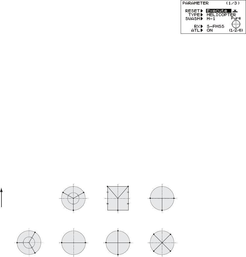
73
HELI-SPECIFIC MENU FUNCTIONS
MODEL TYPE: This function of the PARAMETER submenu is used to select the type of model programming to be used. Before
GRLQJDQ\WKLQJHOVHWRVHWXS\RXUPRGHO¿UVW\RXPXVWGHFLGHZKLFKMODEL TYPEEHVW¿WV\RXUDLUFUDIW,I\RXUWUDQVPLWWHU
is an 8JA, the default is ACRO,ILWLVDQ-+WKHGHIDXOWLVHELI(H-1).
HELICOPTER SWASHPLATE TYPES:
The 8J radios support 8 basic swashplate setups, including "single servo" (H-1PDQ\KHOLFRSWHUVXVHWKLVW\SHDQGW\SHV
of CCPM (cyclic and collective pitch mixing). A "single servo" swashplate uses one servo for each axis: aileron, elevator
F\FOLF SLWFK DQG FROOHFWLYH SLWFK &&30 KHOLFRSWHUV XWLOL]H D FRPELQDWLRQ RI VHUYRV ZRUNLQJ WRJHWKHU WR DFKLHYH WKH
3 axes of motion. There are 7 basic CCPM types, displayed below. CCPM has several advantages, the most obvious of
which is far less mechanical complexity to properly move the swashplate of the helicopter. Additionally, several servos
ZRUNLQJLQXQLVRQH[+5DOOVHUYRVWRJHWKHUFUHDWHHOHYDWRUPRYHPHQWGUDPDWLFDOO\LQFUHDVHVWKHWRUTXHDYDLODEOHDV
well as the precision and centering.
Please note that some helicopters are type HR3 or HN3H[FHSWRIIE\GHJUHHV)RUH[DPSOHWKH.\RVKR® Caliber is
HR3EXWZLWKWKHSDUDOOHOVHUYRVWRWKHUHDURIWKHKHOLFRSWHUQRWIURQW,I\RXUPRGHOVVZDVKSODWHLVRIIE\GHJUHHV
you will still use that swashplate type, but also use SWASH AFR to adjust the functions as needed until it operates properly.
Additionally, different angles of CCPM may also be created utilizing the fully assignable programmable mixes. (See our
)UHTXHQWO\$VNHG4XHVWLRQVDUHDDWZZZIXWDEDUFFRP?IDT?
1RWRSHUDWLQJTXLWHOLNH\RXH[SHFWHG",QPDQ\&&30LQVWDOODWLRQV\RXQHHGWRHLWKHUUHYHUVHWKHGLUHFWLRQRIDVSHFL¿F
function (SWASH AFRRUUHYHUVHDVLQJOHVHUYRVGLUHFWLRQREVERSE). See SWASH AFR for details.
Swashplate Types
HR3H-1 H-3
ELE ELE
ELE1
ELE2
120˚
120˚120˚
PIT
(AIL)
AIL
(PIT)
PIT
(AIL)
AIL
(PIT)
HN3
120˚
120˚
120˚
ELE
PIT
AIL
HE3
ELE
PIT
(AIL)
AIL
(PIT)
PIT
(AIL)
AIL
(PIT)
H-2
PIT
FRONT
AIL
H-4
ELE1
ELE2 AIL
PIT
H4X
(Normal linkage type)
H-1:each servo linked
to the swashplate
independently.
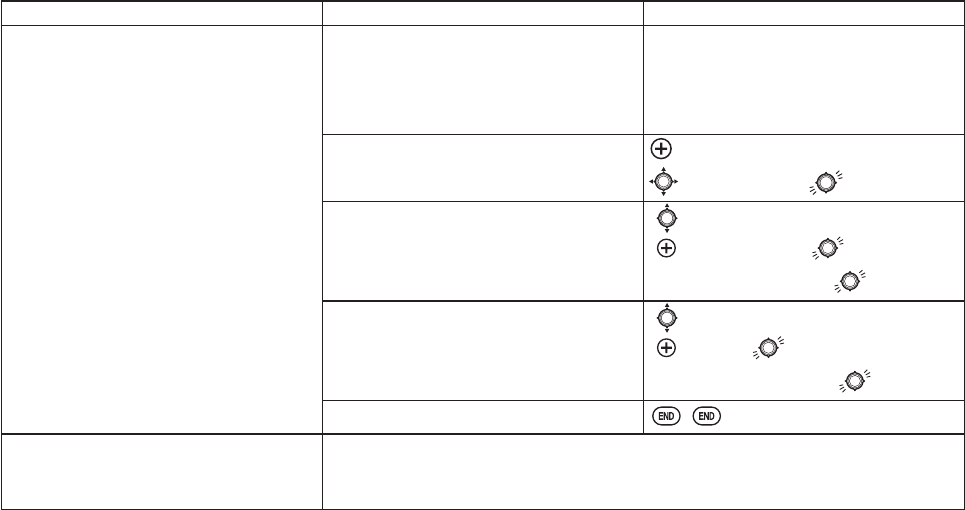
74
GOAL of EXAMPLE: STEPS: INPUTS:
Change the MODEL TYPE and SWASH
TYPE of model #3 from aircraft to 120
GHJUHH&&30ZLWKVHUYRVZRUNLQJLQ
unison for collective pitch and aileron
[HELI(HR3)].
Confirm you are currently using the
proper model memory. (example: 3)
2QKRPHVFUHHQFKHFNPRGHOQDPHDQG
# on top left.
If it is not the correct model (example:3),
see MODEL SELECT.
Open PARAMETER submenu. for 1 second.
to PARAMETER.
Select proper TYPE.
(HELICOPTER)
&RQ¿UPWKHFKDQJH
to TYPE.
to HELICOPTER. for 1 second.
Are you sure? displays. WRFRQ¿UP1
Change to the desired SWASH TYPE
H[DPSOH+5
&RQ¿UPWKHFKDQJH
to SWASH.
to HR3. for 1 second.
Are you sure? displays. WRFRQ¿UP
Close.
Where next? If a single servo is not operating properly, REVERSE: see p. 35.
,IDFRQWUROLVRSHUDWLQJEDFNZDUGVLH(OHYDWRUVHHSWASH AFR, p. 75.
If unsure see SWASH AFR.
15DGLRHPLWVDUHSHDWLQJ³EHHS´DQGVKRZVSURJUHVVRQVFUHHQDVWKHPRGHOW\SHLVEHLQJFKDQJHG1RWHWKDWLIWKHSRZHUVZLWFKLVWXUQHGRIISULRUWR
completion, the model type will not be changed.

75
SWASH AFR (not in SWH1):
Swashplate function rate settings (SWASH AFR) reduce/increase/reverse the rate
(travel) of the aileron, elevator (except H-2 ) and collective pitch functions,
adjusting or reversing the motion of all servos involved in that function, only
when using that function. Since these types utilize multiple servos together to
FUHDWHWKHFRQWUROVVLPSO\DGMXVWLQJDVHUYRVREVERSE or END POINT would not
properly correct the travel of any one control. Since H-1 uses one servo for each
IXQFWLRQWKHUHLVQRQHHGIRU$)5LQH-1.
7KLVLVIDLUO\KDUGWRH[SODLQ EXW HDV\WRVHHVROHWVVHWXS .\RVKR® &DOLEHUVVZDVKSODWHVHWWLQJVDVDQH[DPSOH:LWK
everything installed per factory instructions, set the model to HELI(HR31RZOHWVDGMXVWWKHVZDVKSODWHSURSHUO\
6LQFH DLOHURQ DOZD\V XVHV QR PRUH WKDQ VHUYRV FKHFN LW ¿UVW (LWKHU ERWK RSHUDWH SURSHUO\ QR FKDQJH QHHGHG ERWK
RSHUDWHEDFNZDUGVUHYHUVHWKHZKROHIXQFWLRQRURQHVHUYRRSHUDWHVEDFNZDUGVUHYHUVHWKDWVHUYRDORQH
1H[W FKHFN HOHYDWRU 5HPHPEHU WKH DLOHURQ VHUYRV RSHUDWH FRUUHFWO\ VR LI HOHYDWRU GRHV QRW ZH VKRXOG RQO\ KDYH
choices left—the whole function needs to be reversed, or the servo(s) not shared with aileron need to be reversed.
/DVW LV FROOHFWLYH ,I WKH DLOHURQ DQG HOHYDWRU FRQWUROV DUH ZRUNLQJ SURSHUO\ WKH RQO\ WKLQJ WKDW FRXOG EH ZURQJ LV WKH
direction in which the collective operates (reverse the whole function). In our example, HR3 is 180 degrees off from the
VZDVKSODWHRIWKH&DOLEHU7KHUHIRUHLWLVYHU\OLNHO\WKDWVHYHUDOIXQFWLRQVZLOOQRWRSHUDWHSURSHUO\7KHFROOHFWLYHSLWFK
RSHUDWLRQLVEDFNZDUGVEXWUHYHUVLQJDOOWKUHHVHUYRVZRXOGDOVRUHYHUVHWKHDLOHURQDQGHOHYDWRURSHUDWLRQV&KDQJLQJWKH
collective pitch rate, however, from +50% to -50%, will reverse the collective pitch without affecting the aileron action.
CHECKING FOR PROPER MOTION ON AN HR3 SWASHPLATE
HR3 Swash Type PROPER MOTION WRONG MOTION HOW TO FIX
AILERON STICK. Swashplate tilts right. Swashplate tilts left. Reverse AIL setting in SWASH
to -50%.
%DFNRIVZDVKSODWHPRYHV
up.
&KVHUYRPRYHVLQFRUUHFWO\
REVERSE.
%DFNRI6ZDVKSODWHPRYHV
down.
&KVHUYRPRYHVLQFRUUHFWO\
REVERSE.
ELEVATOR STICK.)URQWRIVZDVKSODWHPRYHV
GRZQEDFNRIVZDVKSODWH
moves up.
Swashplate moves the
opposite.
Reverse ELE setting in SWASH.
(ex: +50 to -50)
Entire swashplate moves up. &KVHUYRPRYHVLQFRUUHFWO\
REVERSE.
RUDDER STICK. The leading edges of tail
blades rotate left.
Blades rotated right. REVERSE the rudder servo.
THROTTLE STICK. Entire Swashplate lifts. Swashplate lowers. Reverse PIT setting in SWASH.
GOAL of EXAMPLE: STEPS: INPUTS:
Adjust the travel of the collective pitch
from +50% to -23%, reversing the travel
of all 3 servos and decreasing their
travel in collective pitch only, on an
HR3 SWASH TYPE.
Open SWASH AFR function. for 1 second.
to SWASH AFR.
Adjust PIT travel to -23%.to PIT. to -23%.
Close the menu.
Where next? &RQ¿UPWKHVZDVKSODWHLVOHYHODWWUDYHODWQHXWUDO$GMXVWDUPVLIQHHGHG
$SSO\IXOOFROOHFWLYHDQGFKHFNWKDWWKHVZDVKSODWHUHPDLQHGOHYHO,IQRWDGMXVW
VHUYRVWUDYHOVDVQHHGHGWRFRUUHFWEND POINT: see p. 36.
Set up the normal condition: (THR-CURV/NOR, PIT-CURV/NOR, REVO./NORM):
see p. 78.
Set up D/R,EXP: see p. 39.
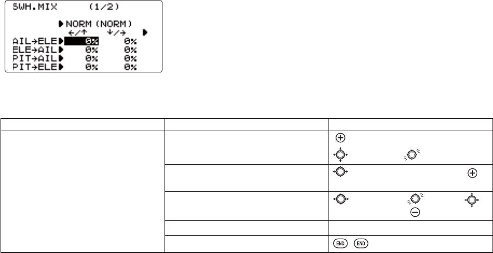
76
Swash Mixing (SWH MIX):
This function can be set for each flight condition, and is used to correct the
tendency of the model to change when the rotor is tilted by aileron, elevator,
and rudder controls.
Adjustability:
0L[LQJPD\EHVHWIURPWRIRUHDFKÀLJKWFRQGLWLRQ
GOAL of EXAMPLE: STEPS: INPUTS:
When the right roll is carried out, an
elevator is down and an adjustment is
needed.
Open SWH MIX function. for 1 second.
to SWH MIX.
Activate the function. to 2/2 page $,/Ȼ(/(0,; to
ON.
Adjust the rate.
Ex: IDL1$,/WR(/(
to 1/2 page to IDL1 to
AIL →ELE, ↓/→ to -10%.
Repeat as needed.
Close the menu.
$FWXDOO\PRYHDPRGHODQGFKHFNDGLUHFWLRQZHOO
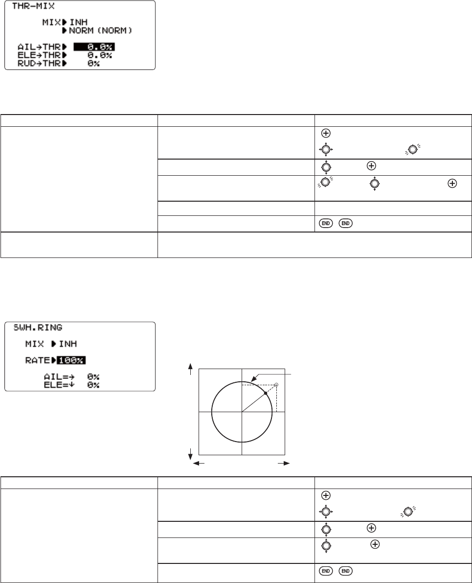
77
Throttle Mixing (THROTTLE MIX):
This function can be set for each flight condition, and is used to correct the
tendency of the model to change altitude when the rotor is tilted by aileron,
elevator, and rudder controls.
Adjustability:
0L[LQJPD\EHVHWIURPWRIRUHDFKÀLJKWFRQGLWLRQ
GOAL of EXAMPLE: STEPS: INPUTS:
Correct the tendency of the model to
change altitude.
Open THROTTLE MIX function. for 1 second.
to THROTTLE MIX.
Activate the function. to MIX to ON.
Adjust the rate.
Ex: IDL1$,/WR7+
to IDL1 to AIL →THR to
10%.
Repeat as needed.
Close the menu.
Where next? HI/LOW-PIT : see p. 86.
GOVERNOR set up: see p. 89.
Swash Ring (SWASH RINGOLPLWVWKHVZDVKSODWHWUDYHOWRD¿[HGUDQJH
7KLV IXQFWLRQ OLPLWV WKH VZDVK WUDYHO WR SUHYHQW GDPDJLQJ WKH VZDVK OLQNDJH
by simultaneous operation of the ailerons and elevators. It is effective in 3D
aerobatics which use a large amount of travel.
GOAL of EXAMPLE: STEPS: INPUTS:
7RSUHYHQWGDPDJLQJWKHVZDVKOLQNDJH
by simultaneous operation of the
ailerons and elevators, set the limit
point where swash throw stops.
*Adjust the rate at the maximum swash
tilt by simultaneous operation of the
ailerons and elevators
Open SWASH RING function. for 1 second.
to SWASH RING.
Activate the function. to MIX to ON.
Adjust the rate.
([
to RATE to 90%.
Close the menu.
6ZDVKWUDYHOE\VLPXOWDQHRXVRSHUDWLRQRI
the ailerons and elevators is limited within the
circle(SWASH RING rate).
Adjustability:
,QLWLDOYDOXH
$GMXVWPHQWUDQJHWR
Aileron operation
Elevator operation

78
Setting up the Normal Flight Condition:7KH1RUPDOÀLJKWFRQGLWLRQLVW\SLFDOO\XWLOL]HGIRUKRYHULQJ7KHWKURWWOHDQG
collective pitch curves are adjusted to provide consistent engine RPM despite the increase/decrease in collective pitch of
WKHEODGHV7KLVNHHSVWKHHQJLQHIURP³ERJJLQJGRZQ´XQGHUH[FHVVLYHORDGOLNHWU\LQJWRDFFHOHUDWHDFDURQDVWHHSKLOO
LQWKJHDURUH[FHVVLYH530XQGHULQVXI¿FLHQWORDGOLNHÀRRULQJWKHWKURWWOHZKLOHLQQHXWUDOULVNLQJHQJLQHGDPDJH
As the 2 curves and revo. mixing are all interrelated.
Note that the normal throttle, pitch and revo curves are all available. These may also be updated later in the menu with the
VHWWLQJVIRUWKHRWKHUFRQGLWLRQV>LGOHXSIDL1LGOHXSIDL2DQGLGOHXSIDL3), plus throttle hold (HOLD)].
Note: The throttle and pitch curves for the normal condition are always on. They cannot be inhibited. The other four
FRQGLWLRQVDUHDFWLYDWHGZLWKWKHLUWKURWWOHFXUYHVRUWKURWWOHKROG)RULGOHXSVVHHS)RUWKURWWOHKROGVHHS
THR-CURV/NOR: inputs the normal (NORM) throttle curve, which is usually not a linear response to THROTTLE STICK
PRWLRQ$GMXVWLQJ SRLQW RI WKH FXUYH DGMXVWV WKHHQJLQH¶V 530 DWWKH THROTTLE STICK midpoint, the desired
position for hovering. The other 4 points are then adjusted to create the desired idle and maximum engine speed, and a
VPRRWKWUDQVLWLRQLQEHWZHHQ)RUPRUHRQWKURWWOHFXUYHVVHHS
PIT-CURV/NOR: inputs the normal (NORM FROOHFWLYH SLWFK FXUYH WKH FROOHFWLYH SLWFK FXUYH IRU ÀLJKW QHDU KRYHU 7KH
normal collective pitch curve is adjusted to match the throttle curve, providing the best vertical performance at a constant
HQJLQHVSHHGZLWKDVWDUWLQJFXUYHRI3EDVHQHXWUDODQGWRGHJUHHVRIEODGHSLWFKPD[LPXP<RXFDQ
SURJUDPWKHUHVSRQVHRYHUDSRLQWFXUYHIRUWKHEHVWFROOHFWLYHSLWFKDQJOHVUHODWLYHWRTHROTTLE STICK movement.
)RUPRUHRQFROOHFWLYHSLWFKFXUYHVVHHS
REVO./NORM: mixes collective pitch commands to the rudder (a PITCH-RUDDER mix) to suppress the torque generated
E\FKDQJHVLQWKHPDLQURWRUVFROOHFWLYHSLWFKDQJOHNHHSLQJWKHPRGHOIURP\DZLQJZKHQWKURWWOHLVDSSOLHGREVO. is
H[WUHPHO\KHOSIXOLQ³WDPLQJWKHWDLO´RIPRGHOVQRWXVLQJKHDGLQJKROGAVCS gyros.
NOTE: There are three revo. mixes available: normal (NORMLGOHXSIDL1/2DQGLGOHXSIDL3). Never use revo.
PL[LQJLQ FRQMXQFWLRQZLWK KHDGLQJKROG$9&6 J\URV )RU GHWDLOVRQ UHYRLQFOXGLQJ GHIDXOWSRLQWV IRUFORFNZLVH DQG
FRXQWHUFORFNZLVHURWDWLQJURWRUVVHHS
7KHVH GHIDXOW UHFRPPHQGDWLRQV DVVXPH \RX DUH GRLQJ IRUZDUG ÀLJKW ,I \RX DUH MXVW OHDUQLQJ SOHDVH IROORZ \RXU LQVWUXFWRU¶V JXLGDQFH 6RPH
LQVWUXFWRUVOLNHDEDVHSRLQWIRUWUDLQLQJVRWKDWWKHKHOLFRSWHUFRPHVGRZQYHU\VORZO\HYHQLI\RXULQVWLQFWVSXOOWKHWKURWWOHFROOHFWLYHVWLFNWR
the bottom in a hurry.
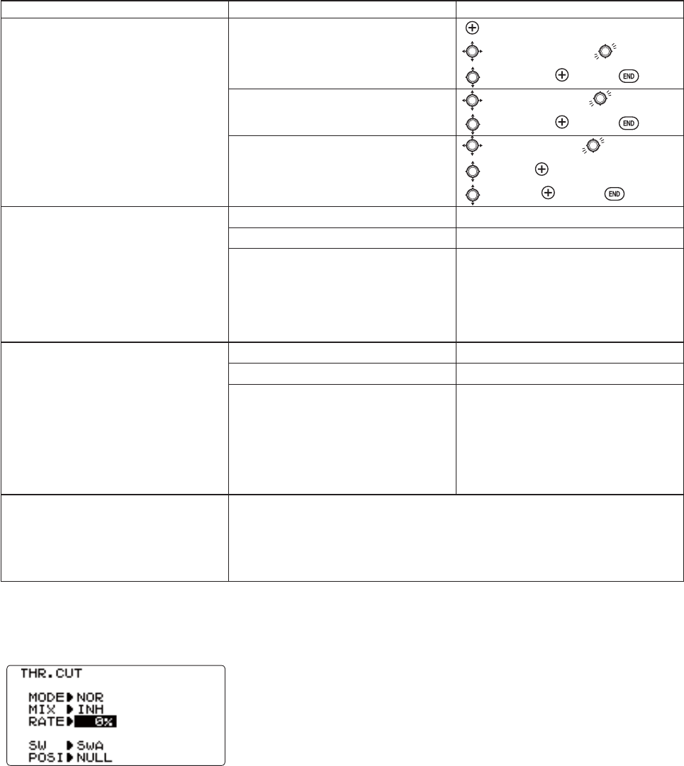
79
GOAL of EXAMPLE: STEPS: INPUTS:
Set up Normal Flight Condition
Throttle/Collective Pitch Curves and
Revo.
Base point: Adjust base point of throttle
curve until engine idles reliably on the
ground. Adjust base point of collective
SLWFKFXUYHWRDFKLHYHGHJUHHVRI
blade pitch. Apply throttle until the
PRGHOVLWVµOLJKW¶RQLWVVNLGV$GMXVW
base point of REVO. until model does not
rotate its nose at all.
Open the THR-CURV/NOR function.
$GMXVWWKH¿UVWSRLQW([5%.)
for 1 second.
to THR-CURV/NOR.
to POINT-1. to 5%.
Open the PIT-CURV/NOR function.
$GMXVWWKH¿UVWSRLQW([8%.)
to PIT-CURV/NOR.
to POINT-1. to 8%.
Open the REVO. /NORM function.
Adjust the high point. (Ex: 4%.)
to REVO. /NORM.
to MIX. to ON.
to HIGH. to 4%.
+RYHUSRLQWAdjust collective pitch
curve to +5 degrees. Ease heli into a
hover. Land/shut engine off. Adjust
throttle curves and rudder trim. Repeat
until model hovers smoothly at half
throttle. Rapidly apply throttle from 1/4
WRVWLFN$GMXVWREVO. until the nose
does not change heading.
Adjust THR-CURV/NOR. Repeat above as needed.
Adjust PIT-CURV/NOR. Repeat above as needed.
Adjust REVO. /NORM. Repeat above as needed.
+LJKSRLQW Adjust collective pitch
FXUYHWRWRGHJUHHV)URPKRYHU
throttle up rapidly. If engine bogs,
increase the throttle curve. If engine
RYHUUHYV LQFUHDVH WKH FROOHFWLYH SLWFK
curve at points 4 or 5. Apply full throttle
ZKLOHKRYHULQJWKHQGHVFHQGEDFNWRD
hover. Adjust REVO. until the nose does
not change heading.
Adjust THR-CURV/NOR. Repeat above as needed.
Adjust PIT-CURV/NOR. Repeat above as needed.
Adjust REVO. /NORM. Repeat above as needed.
Where next? GYRO function: see p. 87.
Adjust HOV-THR and HOV-PIT if needed: see p. 85.
6HWWLQJXS7KURWWOH+ROGVHHS
GOVERNOR function: see p. 89.
D/R,EXP: see p. 39.
THROTTLE CUT:
The THROTTLE-CUTIXQFWLRQLVXVHGWRNLOOWKHHQJLQHDWWKHHQGRIDÀLJKW7KHHQJLQHFDQEHVWRSSHGZLWKRQHWRXFKRI
DQ\VZLWFKHOLPLQDWLQJWKHQHHGWRPRYHWKHWULPWRNLOOWKHHQJLQHDQGWKHQUHDGMXVWSULRUWRHDFKÀLJKW7KHKHOLFRSWHU
THROTTLE-CUT LQFOXGHV DQ 212)) WKURWWOH SRVLWLRQ QRUPDOO\ D OLWWOH DERYH
idle). You must move the THROTTLE STICKEDFNEHORZWKHVHWSRLQWEHIRUH
the THROTTLE-CUT function can be reset, to avoid sudden engine acceleration.
)RUDGHWDLOHGH[DPSOHRIWKURWWOHFXWVHWXSVHHACRO p. 38.
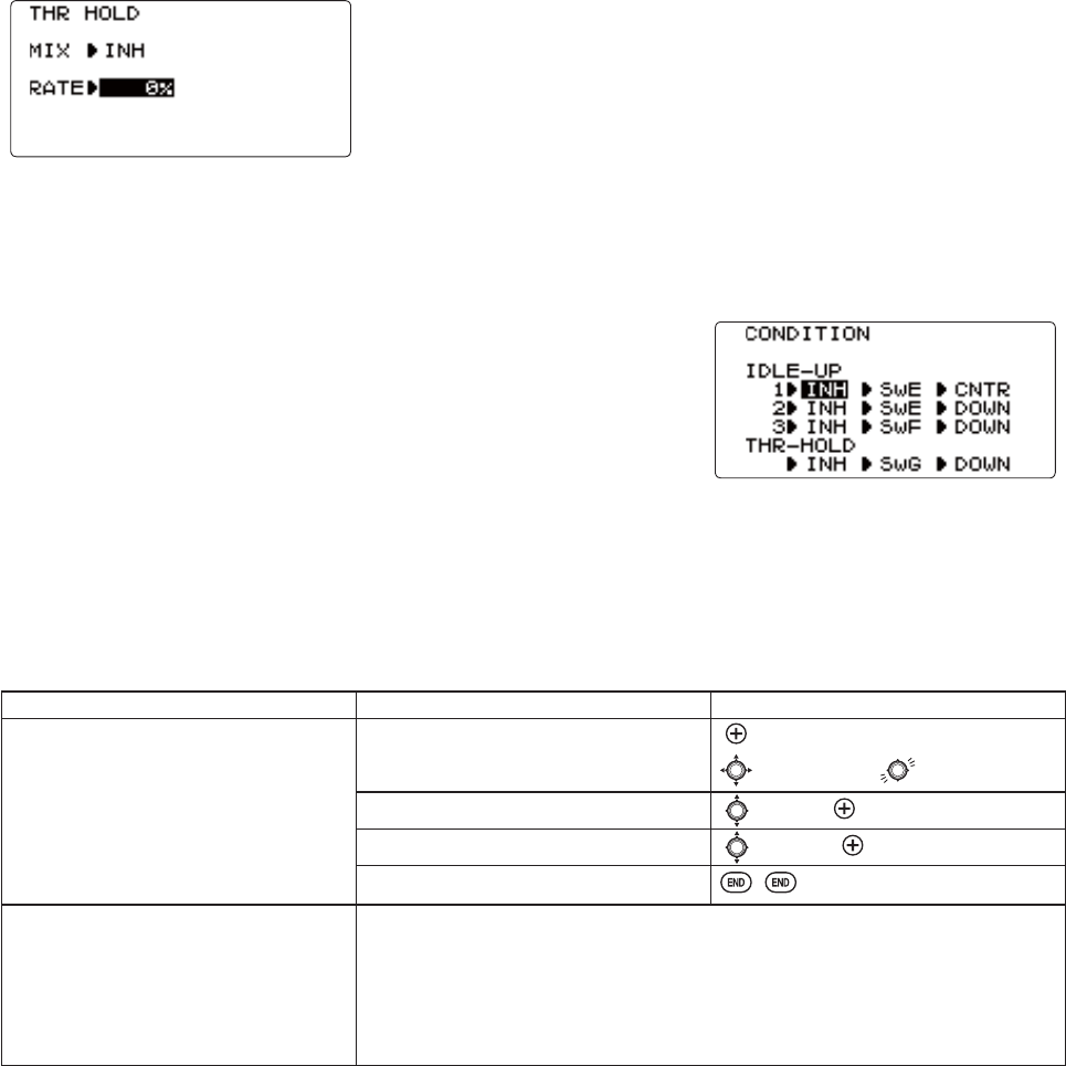
80
THR-HOLD: This function holds the engine in the idling position and disengages it from the THROTTLE STICK when
SWITCH E-+RU*-$LVPRYHG,WLVFRPPRQO\XVHGWRSUDFWLFHDXWRURWDWLRQ
Prior to setting up THR-HOLDKRRNXSWKHWKURWWOHOLQNDJHVRWKDWWKHFDUEXUHWRU
is opened fully at high throttle. Then, use the digital trim to adjust the engine
idle position. To have THR- HOLD maintain idle, move the THROTTLE STICK to
WKHLGOHSRVLWLRQ7KHQPRYHWKHKROG6:,7&+RQDQGRIIDQGNHHSFKDQJLQJ
the offset value until the servo does not move. To lower the engine idle speed,
or if you want to shut the engine off, input a higher negative number.
Adjustability:
,GOLQJSRVLWLRQRange of -50% to +50% centered about the throttle idle position to get the desired engine RPM.
6ZLWFKDVVLJQPHQW Assigned to SWITCH G (8JA) or E-+GRZQ
Adjustable in the CONDITION SELECT (THR-HOLD item).
SRVLWLRQW\SHVZLWFKRQO\
Throttle curve: Since the throttle is moved to a single preset position, no curve
is available for THR-HOLD.
Collective pitch curve: Independent curve, typically adjusted to create a blade
SLWFKUDQJHRI°
to +10°
to +12°
, is automatically activated with THR-HOLD.
5HYRPL[ Since revo. mix adjusts for torque from the engine, no revo. mix is
available for THR-HOLD.
Priority:7KHWKURWWOHKROGIXQFWLRQKDVSULRULW\RYHULGOHXS%HVXUHWKDWWKHWKURWWOHKROGDQGLGOHXSSWITCHES are
in the desired positions before trying to start the engine. (We recommend starting your engine in throttle hold for safety
reasons.)
*\UR Gyro programming includes an option to have a separate gyro setting for each condition, including THR-HOLD.
This avoids the potential problem of the user being in the wrong gyro setting when going to THR-HOLD, resulting in an
improper rudder offset and the model pirouetting.
GOAL of EXAMPLE: STEPS: INPUTS:
Set up throttle hold.
Determine desired throttle position of
the idling engine, turn on THR-HOLD, and
adjust percentage as required to reach
the desired running point.
Open THR-HOLD function. for 1 second.
to THR-HOLD.
Activate the function. to MIX. to OFF.
Set desired engine position. to RATE. to desired percent.
Close.
Where next? PIT-CURVEIRU7+5+2/'VHHS
DELAY for THR-HOLD (to ease collective pitch response): see p. 84.
GYRO setup: see p. 87.
6HWWLQJXSWKH,GOH8SV7KURWWOHDQG&ROOHFWLYHSLWFK&XUYHVDQG5HYR
Mixing(TH-CURVE, PIT-CURVE, REVO. MIXIRULGOHXSVVHHS
D/R,EXP: see p. 39.

81
THR-CURVE and PIT-CURVE7KHVHSRLQWFXUYHVDUHXWLOL]HGWREHVWPDWFKWKHEODGHFROOHFWLYHSLWFKWRWKHHQJLQH530IRU
FRQVLVWHQWORDGRQWKHHQJLQH&XUYHVDUHVHSDUDWHO\DGMXVWDEOHIRUQRUPDOLGOHXSLGOHXSDQGLGOHXS,QDGGLWLRQ
a separate collective pitch curve is available for throttle hold. Sample curves are displayed in the appropriate setup types (ex:
QRUPDOÀLJKWFRQGLWLRQSIRUFODULW\
6XJJHVWHGGHIDXOWV
1RUPDO&ROOHFWLYHSLWFKFXUYHWKDWUHVXOWVLQSRLQWVDQGSURYLGLQJWRGHJUHHVSLWFK$WKURWWOH
FXUYHVHWWLQJRI
,GOHXSV,GOHXSVDQGDUHW\SLFDOO\WKHVDPHH[FHSWIRUWKHJ\URVHWWLQJVZLWKRQHEHLQJKHDGLQJKROG$9&6
DQGWKHRWKHUEHLQJQRUPDOPRGH7KHSLWFKFXUYHZLOOOLNHO\EHVLPLODUWRWKHQRUPDOFXUYHDERYH
,GOHXS&ROOHFWLYHSLWFKFXUYHWKDWUHVXOWVLQSRLQWVDQGSURYLGLQJWRWRGHJUHHV$WKURWWOH
curve of 100, 70, 50, 70, 100 to provide full throttle for inverted maneuvers.
7KURWWOH+ROGSLWFKFXUYH6WDUWZLWKWKHQRUPDOSLWFKFXUYHIRULQYHUWHGDXWRVVWDUWIURPWKHLGOHXSSLWFKFXUYHEXW
LQFUHDVHWKHODVWSRLQWDSSUR[LPDWHO\LIDYDLODEOHWRHQVXUHVXI¿FLHQWSLWFKDWODQGLQJ
7KHVH GHIDXOW UHFRPPHQGDWLRQV DVVXPH \RX DUH GRLQJ IRUZDUG ÀLJKW ,I \RX DUH MXVW OHDUQLQJ SOHDVH IROORZ \RXU LQVWUXFWRU¶V JXLGDQFH 6RPH
LQVWUXFWRUVOLNHDEDVHSRLQWIRUWUDLQLQJVRWKDWWKHKHOLFRSWHUFRPHVGRZQYHU\VORZO\HYHQLI\RXULQVWLQFWVSXOOWKHWKURWWOHFROOHFWLYHVWLFNWR
the bottom in a hurry.)
Adjustability:
$XWRPDWLFDOO\VHOHFWHGZLWKWKHSURSHUFRQGLWLRQ
7KHLGOHXS FXUYHV DUHSURJUDPPHGWRPDLQWDLQFRQVWDQW 530 HYHQZKHQWKHFROOHFWLYHSLWFKLV UHGXFHG GXULQJÀLJKW
(including inverted).
7RFKDQJHZKLFKFRQGLWLRQ¶VFXUYHLVEHLQJHGLWHGFXUVRUXSWRCOND and change the curve named. Conditions can also
be chosen by pushing(long time)JOG KEY.
)RUFODULW\WKHQDPHRIWKHFRQGLWLRQFXUUHQWO\DFWLYHVZLWFKHGRQLQWKHUDGLRLVVKRZQLQSDUHQWKHVHVEHKLQGWKHQDPH
of the condition whose curve is being edited. (Example: see curve displays below. Note that the normal condition is
DFWLYHEXWWKHLGOHXSFRQGLWLRQ¶VFXUYHVDUHFXUUHQWO\EHLQJHGLWHG
&RS\LQJWKHFXUYH7RFRS\WKHFXUUHQWFXUYHRQWRDQRWKHUFRQGLWLRQ¶VFXUYHFXUVRUXSWRCOND and press the JOG KEY
for one second. Then select to desired condition and press the +− KEY .
,GOHXSVDQGWKURWWOHKROGSLWFKFXUYHVPD\EHHGLWHGHYHQEHIRUHWKHFRQGLWLRQVKDYHEHHQPDGHDFWLYH$FWLYDWLQJWKHLU
throttle curves activates these conditions.
REVO. MIX: This mix adds opposite rudder input to counteract the changes in torque when the speed and collective pitch of
the blades is changed.
Adjustability:
7KUHHVHSDUDWHFXUYHVDYDLODEOHQRUPDOIRUKRYHULQJLGOHXSVDQGFRPELQHGDQGLGOH
&RUUHFWPL[LVDXWRPDWLFDOO\VHOHFWHGLQÀLJKWZLWKHDFKFRQGLWLRQDQGDXWRPDWLFDOO\DFWLYDWHGZKHQWKHWKURWWOHVHWXSIRU
that condition is activated in the programming (i.e. THROTTLE HOLD or THR-CURVE.)
7R FKDQJH ZKLFK FRQGLWLRQ¶V FXUYH LV EHLQJ HGLWHG FXUVRU XS DERYH POINT5 DQG VHOHFW )RU FODULW\ WKH QDPH RI WKH
condition currently active (switched on at the radio) is shown in parentheses behind the name of the condition whose
curve is being edited.
5HYRPL[LQJUDWHVVHWXSRI+,*+DQG/2:FDQEHSHUIRUPHG)RUDFORFNZLVHWXUQLQJURWRUWKHUXGGHULVPL[HGLQWKH
FORFNZLVHGLUHFWLRQZKHQFROOHFWLYHSLWFKLVLQFUHDVHGIRUFRXQWHUFORFNZLVHWXUQLQJWKHRSSRVLWH&KDQJHWKHRSHUDWLQJ
GLUHFWLRQVHWWLQJE\FKDQJLQJWKHVLJQVRIWKHQXPEHUVLQWKHFXUYHIURPSOXVWRPLQXVDQGYLFHYHUVD6XJJHVWHG
defaults:
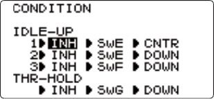
82
&ORFNZLVHURWDWLRQ+,*+!/2:!
&RXQWHUFORFNZLVHURWDWLRQ+,*+!/2:!
$GMXVWWRWKHDFWXDOYDOXHVWKDWZRUNEHVWIRU\RXUPRGHO
5HYR FXUYHV IRU LGOHXSV DUH RIWHQ YVKDSHG WR SURYLGH SURSHU UXGGHU LQSXW ZLWK QHJDWLYH SLWFK DQG LQFUHDVHG WKURWWOH
GXULQJ LQYHUWHG ÀLJKW 5XGGHU LV QHHGHG WR FRXQWHU WKH UHDFWLRQ ZKHQHYHU WKHUH LV LQFUHDVHG WRUTXH ,Q LQYHUWHG ÀLJKW
WKURWWOHVWLFNEHORZKDOIKDVLQFUHDVHGWKURWWOHDQGQHJDWLYHSLWFKWKHUHIRUHLQFUHDVLQJWRUTXHDQGURWDWLQJWKHKHOLFRSWHU
unless the revo. mix is also increasing appropriately.)
IDLE-UPS: DGGLWLRQDO ÀLJKW FRQGLWLRQV DYDLODEOH VSHFL¿FDOO\ IRU KHOLFRSWHUV 7KHVH DGGLWLRQDO ÀLJKW FRQGLWLRQV FRQWDLQ
different throttle curves, collective pitch curves, revo. mixing, and trims (except IDLE-3WRPDNHWKH KHOLFRSWHU SHUIRUP
certain maneuvers more easily. Lastly, the gyro and dual rate functions may be set to provide separate rates per condition
VHOHFWHGLQFOXGLQJRQHIRUHDFKLGOHXS
2QHRIWKHPRVWFRPPRQÀLJKWFRQGLWLRQVLVVHWXSWRDOORZWKHKHOLFRSWHUWRHDVLO\ÀLSIURPXSULJKWWRLQYHUWHGDQGEDFN
7RGRVRWKHSLWFKFXUYHLVVHWWRSLWFKDWKDOIVWLFNSRVLWLYHSLWFKFOLPEXSULJKWDERYHKDOIDQGQHJDWLYHSLWFKFOLPE
ZKHQ LQYHUWHG EHORZ KDOI VWLFN 7KH WKURWWOH FXUYH LV DGMXVWHG WR DOORZ WKH HQJLQH WR UXQ FRQVLVWHQWO\ WKURXJKRXW WKH
changes in pitch.
$GGLWLRQDO LGOHXSV PD\ EH XVHG WR PD[LPL]H WKH KHOLFRSWHUV IOLJKW FKDUDFWHULVWLFV LQ FHUWDLQ W\SHV RI IOLJKW LH IDVW
IRUZDUGPRWLRQEDFNZDUGRUPDQHXYHUVORRSVUROOVVWDOOWXUQVRUHYHQWKHVDPHPDQHXYHUEXWFKDQJLQJIURPKHDGLQJ
KROG$9&6J\URPRGHWRQRUPDOJ\URPRGH7KH-SURYLGHVLGOHXSVWRDOORZWKHPRGHOHUDGGLWLRQDOVHWXSVDORQJ
ZLWKWKHQRUPDOÀLJKWFRQGLWLRQ
Adjustability:
SWITCH G (8JA) or E-+LVSURJUDPPHGIRUQRUPDONORMLGOHXSIDLE-UP1DQGLGOHXSIDLE-UP2) curves.
Adjustable in the CONDITION SELECT (IDLE-UP1/2,IDLE-UP3 items).
(IDLE-UP1/2SRVLWLRQW\SHVZLWFKRQO\IDL3SRVLWLRQW\SHVZLWFKRQO\
$FWLYDWHGZLWKWKHWKURWWOHFXUYHIRUWKDWFRQGLWLRQLQTHR-CURVE.
&XUYHVDUHDGMXVWHGWRPDLQWDLQFRQVWDQW530HYHQZKHQWKHFROOHFWLYHSLWFK
is negative (inverted).
1RWHWKDWREVO. PL[LQJKDVRQHFXUYHIRULGOHXSVDQGDQGDVHFRQGFXUYH
MXVWIRULGOHXS
*\URVHWWLQJVPD\EHVHWVHSDUDWHO\IRUHDFKLGOHXS
$FWLYDWLQJOFFSETPDNHVWKHTRIM LEVERS adjust the trim separately in each
RIWKHLGOHXSFRQGLWLRQV
)RUDQH[DPSOHRIWKURWWOHDQGSLWFKFXUYHVDQGUHYRSOHDVHVHH1RUPDO)OLJKW&RQGLWLRQ6HWXSS
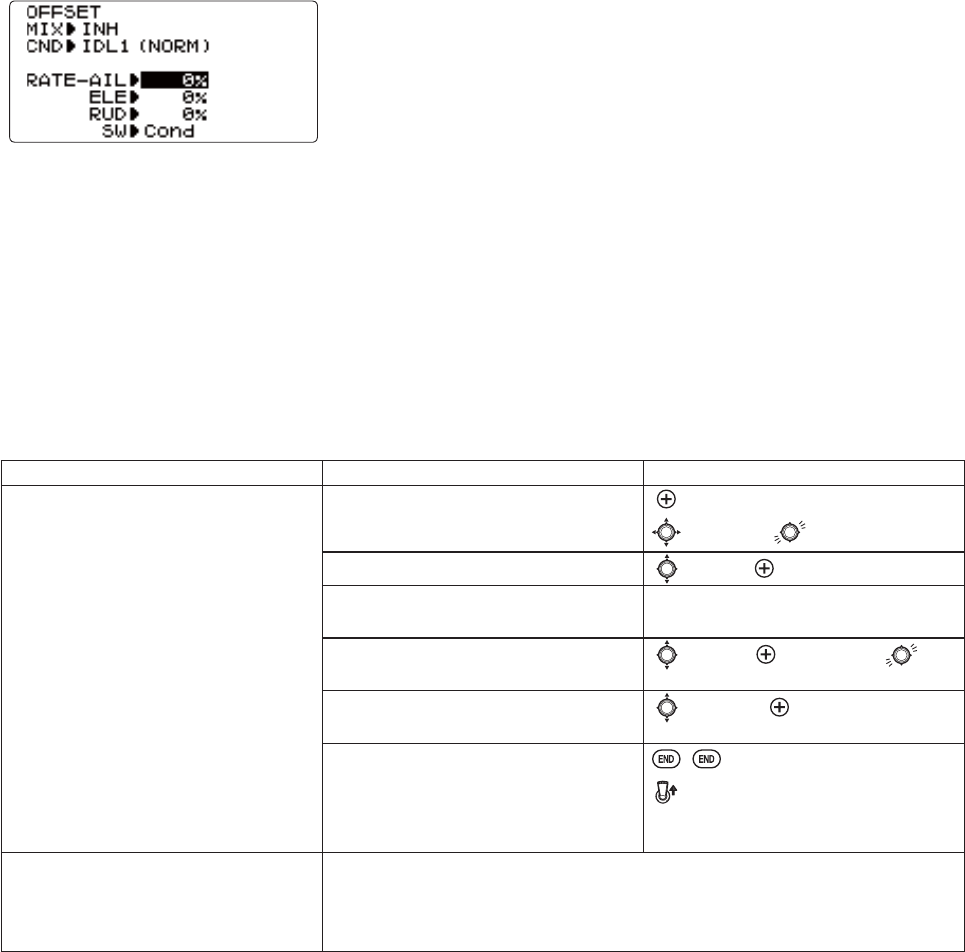
83
OFFSET: Optional separate trims in addition to those for the normal condition. This function is used to automatically change
WKHWULP RI DKHOLFRSWHU)RU H[DPSOH ZKHQWUDQVLWLRQLQJ IURPKRYHU WR À\LQJDW KLJKVSHHG D FORFNZLVHURWDWLRQURWRU
helicopter tends to drift to the right at high speeds, so an aileron offset may be applied to offset the helicopter to the left.
The necessary elevator offset varies with model geometry, so it must be determined by noting collective pitch changes at
high speed. The rudder offset is affected by both revo. mixing and trim lever movement while in the offset function.
Adjustability:
&RPSOHWH VZLWFK DVVLJQDELOLW\ SOXV D CONDITION SELECT option that creates/
VZLWFKHVEHWZHHQLQGLYLGXDOWULPVIRUHDFKRIWKHLGOHXSV
:KHQOFFSET is active (its switch is on), moving the TRIM LEVERS adjusts
the stored offset, not the trims in the normal condition.
:KHQOFFSET is inactive (its switch is off), the OFFSET and any trim adjustments
WRLWKDYHQRHIIHFWPRGHOREH\VWKHWULPVHWWLQJVRIWKHFXUUHQWO\DFWLYHÀLJKW
condition.)
:KHQOFFSETLVLQKLELWHGWULPDGMXVWPHQWVPDGHLQDQ\ÀLJKWFRQGLWLRQDIIHFW
DOOÀLJKWFRQGLWLRQV
5DSLGMXPSVFDXVHGE\ODUJHRIIVHWVFDQEHVORZHGXVLQJWKHDELAY function.
*During OFFSET operation, the aileron, elevator, and rudder travels are displayed on each trim
display in the Startup screen.
NOTE: 5HPHPEHU RIIVHWV DQG UHYR PL[HV DUH QRW UHFRPPHQGHG ZKHQ XVLQJ KHDGLQJKROG$9&6 J\URV EHFDXVH WKH\
FRQÀLFWZLWKWKHDXWRPDWLFFRUUHFWLRQVWRWULPDQGWRUTXHWKDW$9&6SURYLGHV
GOAL of EXAMPLE: STEPS: INPUTS:
Set up separate trims for each of the
WKUHHLGOHXSFRQGLWLRQV
$GMXVWWKHLGOHXSUXGGHUWULPWR
correct for torque at high speeds.
Open the OFFSET function. for 1 second.
to OFFSET.
Activate the function. to MIX. to OFF or ON.
Change switch setting to Cond.
(No need to change SW.)
already Cond.
Select IDL2.to No.to IDL2. or for 1
second to IDL2.
Adjust trim settings as needed.
(Ex:rudder to +8%.)
to RUDD. to +8%.
&ORVH PHQXV DQG FRQ¿UP GLIIHUHQFH LQ
WULPVEHWZHHQQRUPDODQGLGOHXS E7-+RUG (T8JA) from
NORMAL to IDL2&KHFNWKDWUXGGHUWULP
changes.
Where next? DELAY: see p. 84.
THR-HOLD: see p. 80.
6HWWLQJXSWKH,GOH8SV7KURWWOHDQG&ROOHFWLYHSLWFK&XUYHVDQG5HYR0L[LQJ
(THR-CURVE, PIT-CURVE, REVO. MIXIRULGOHXSVVHHS
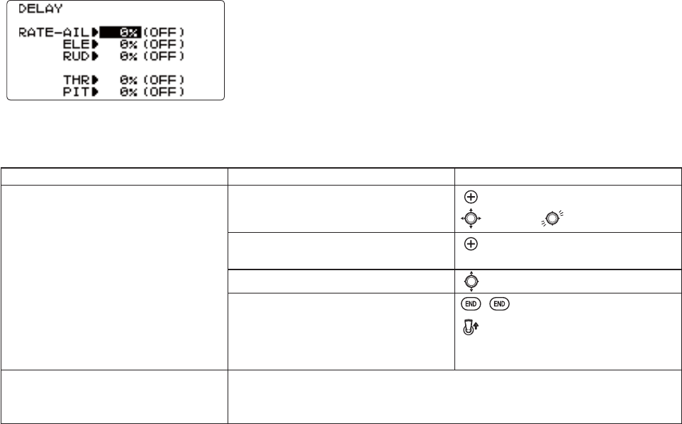
84
DELAY: The Delay function provides a smooth transition between the trim positions whenever OFFSET,REVO. MIXING, or
THROTTLE HOLD functions are turned on and off.
Adjustability:
6HSDUDWH GHOD\ WLPHV DUH DYDLODEOH IRU DLOHURQ HOHYDWRU UXGGHU WKURWWOH DQG
pitch.
:LWKDGHOD\VHWWLQJWKHVHUYRWDNHVDERXWDKDOIVHFRQGWRPRYHWRLWV
new position...quite a long time.
,QJHQHUDOGHOD\VRIDSSUR[LPDWHO\DUHVXI¿FLHQW
GOAL of EXAMPLE: STEPS: INPUTS:
Set up a delay on all channels to ease
WKH WUDQVLWLRQ IURP RQH ÀLJKW FRQGLWLRQ
to another so there are no "hard jumps."
Open the DELAY function. for 1 second.
to DELAY.
Adjust AILE response as needed. (Ex:
aileron to +8%.)
to +8%.
Repeat for other channels. to ELEV. Repeat step above.
Close menus and confirm slowed
transitions. E7-+RUG (T8JA) from
NORMAL to IDL2&KHFNWKDWVHUYRV
move gradually to new positions.
Where next? THR-HOLD: see p. 80.
6HWWLQJXSWKH,GOH8SV7KURWWOHDQG&ROOHFWLYHSLWFK&XUYHVDQG5HYR0L[LQJ
(THR-CURVE, PIT-CURVE, REVO. MIXIRULGOHXSVVHHS
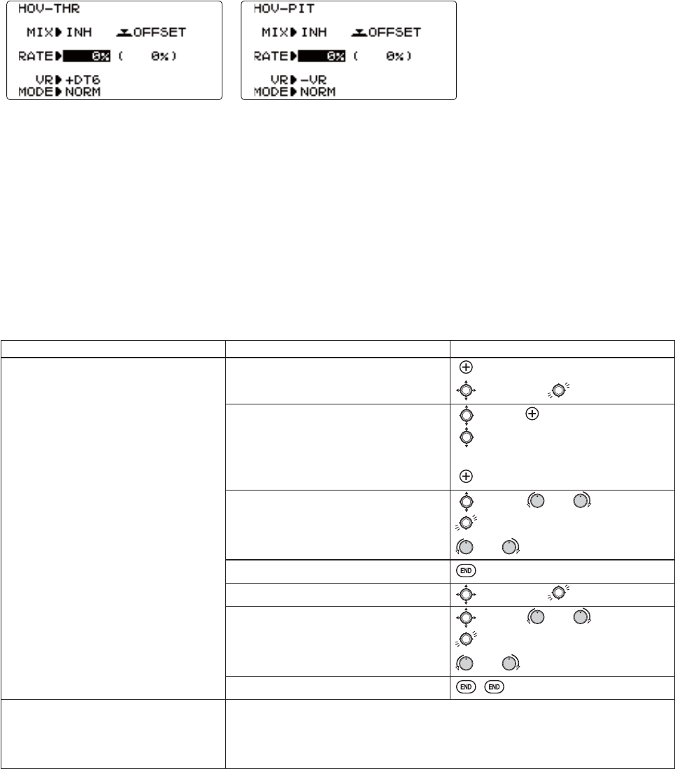
85
HOVERING ADJUSTMENTS (HOV-THR and HOV-PIT):
+RYHULQJWKURWWOHDQGKRYHULQJSLWFKDUH¿QHWXQLQJDGMXVWPHQWVIRUWKHWKURWWOHDQGFROOHFWLYHSLWFKFXUYHVLQGLYLGXDOO\
DIIHFWLQJSHUIRUPDQFHRQO\DURXQGWKHFHQWHUSRLQWDQGRQO\LQWKHQRUPDOFRQGLWLRQ7KH\DOORZLQÀLJKWWZHDNLQJRIWKH
curves for ideal setup.
Adjustability:
5RWRUVSHHGFKDQJHVFDXVHGE\WHPSKXPLGLW\DOWLWXGHRURWKHUFKDQJHVLQÀ\LQJFRQGLWLRQVDUHHDVLO\DFFRPPRGDWHG
%RWKDGMXVWPHQWVPD\EHLQKLELWHGLIQRWGHVLUHG
%RWKDGMXVWPHQWVPD\DOVREHVHWWRNULLWHPSRUDULO\WXUQLQJRIIWKHNQREEXWPDLQWDLQLQJWKHODVWPHPRUL]HGVHWWLQJ
$GMXVWPHQWVPD\EHPHPRUL]HGDQGWKHQWKHNQREVUHWXUQHGWRFHQWHUSRLQWWRXVHWKDWDPRXQWRI DGMXVWPHQW$OORZV
HDV\XVHRIWKHWULPPLQJNQREVIRUPXOWLSOHPRGHOV1RWHWKDWZKHQPHPRUL]DWLRQLVUHSHDWHGZLWKWKHNQRERIIVHWIURP
center, the trim value accumulates.)
$GMXVWPHQWVDUHTXLFNO\UHVHWWRWKHLQLWLDOYDOXHE\WXUQLQJWKHGLDOXQWLOWKHWULPUHDGVPHPRUL]LQJWKHQUHWXUQLQJ
WKHNQREWRLWVFHQWHUSRVLWLRQ
1RWHWKDWDOOIXQFWLRQVLQFOXGLQJWKHVHDVVXPHWKHPRGHOKRYHUVDWKDOIVWLFN
$YDLODEOHLQQRUPDONORMRUQRUPDOLGOHXSNORM/IDL1) condition only.
GOAL of EXAMPLE: STEPS: INPUTS:
)LQHWXQHKRYHULQJZLWKWKHKRYHULQJ
adjustments. Remember these affect
only the hovering (normal) condition.
Adjust throttle and collective pitch
curves until the model hovers nicely. In
ÀLJKWDGMXVWFROOHFWLYHSLWFKDQGWKURWWOH
curves near hover point independently
with HOV-THR and HOV-PITNQREV
6WRUHQHZVHWWLQJVDIWHUÀLJKW
Open the HOV-PIT function. for 1 second.
to HOV-PIT.
2SWLRQDOFKDQJHZKLFKNQREDGMXVWV
HDFKKRYHULQJFXUYHNULLORFNVLQ
FXUYHLQODVWVWRUHGSRVLWLRQ
to MIX. to ON
WR VR 6HOHFW 95 95 '7
'7'7'7RU18//
WRGHVLUHGNQREDQGGLUHFWLRQ
Store the current dial settings prior to
selecting another model.
to RATE. or VR to setting.
to store.
or VR to center.
Close.
Open the HOV-PIT function. to HOV-PIT.
Store the current dial settings prior to
selecting another model.
to RATE. or VR to setting.
for one second to store.
or VR to center.
Close.
Where next? THR-HOLD: see p. 80.
6HWWLQJXSWKH,GOH8SV7KURWWOHDQG&ROOHFWLYHSLWFK&XUYHVDQG5HYR0L[LQJ
(TH-CURVE, PIT-CURVE, REVO. MIXIRULGOHXSVVHHS
D/R,EXP: see p. 39.
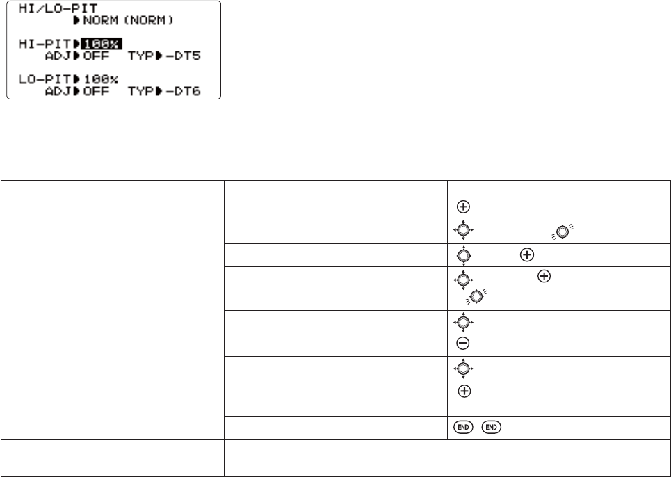
86
HIGH/LOW PITCH (HI/LO-PIT):
7KLVIXQFWLRQPD\EHXVHGWRDGMXVWWKHFXUYHVKLJKDQGORZVLGHLQGLYLGXDOO\IRUHDFKÀLJKWFRQGLWLRQQRUPDOLGOHXS
LGOHXSLGOHXSWKURWWOHKROG
Adjustability:
<RX PD\ GH¿QH KLJK DQG ORZ VLGH UDWH WULP NQREV WKH KLJK VLGH SLWFK WULP
FRQWUROLVGH¿QHGDVWKH'7DWLQLWLDOVHWWLQJ
7KHFRQGLWLRQVDUHDFWLYDWHGLQWKHCONDITION SELECT function (p.78).
%RWKDGMXVWPHQWVPD\EHVHWWRMANUALWHPSRUDULO\WXUQLQJRIIWKHNQRE
$GMXVWPHQWVPD\EHPHPRUL]HG7KHQWKHNQREVFDQEHUHWXUQHGWRWKHFHQWHU
SRLQWWRXVHWKDWDPRXQWRIDGMXVWPHQW$OORZVHDV\XVHRIWKHWULPPLQJNQREV
for multiple models.
GOAL of EXAMPLE: STEPS: INPUTS:
6HWXSDKLJKSLWFKFXUYHLQWKHLGOHXS
1 condition.
6WRUHQHZVHWWLQJVDIWHUÀLJKW
Open the HI/LO-PIT function. for 1 second.
to HI/LO-PIT.
A function is turned on. to ADJ.
6HOHFWWKHLGOHXSFRQGLWLRQ to NORM. to IDL1.
or for 1 second to IDL1.
Set the rate. (Ex: 80%)to HI-PIT.
to 80%.
2SWLRQDOFKDQJHZKLFKNQREDGMXVWV
KLJKSLWFKFXUYH
to +DT5 or -DT5.
WRGHVLUHGNQRERUWULPDQG
direction.
Close.
Where next? PIT-CURVE: see p. 81.
HOV-PIT: see p. 85.
87
*<526DQG*29(512568VLQJHOHFWURQLFVWRWDNHVRPHRIWKHFRPSOH[LW\RXWRIVHWXSVDQGÀLJKW
:KDWLVDJ\UR"$J\URVFRSHLVDQHOHFWURQLFXQLWWKDWVHQVHVPRWLRQDQGFRUUHFWVIRULW)RUH[DPSOHLIWKHZLQGEORZV
\RXUKHOLFRSWHU¶VWDLOWRWKHOHIWDJ\URZLOOVHQVHWKDWPRWLRQFRQ¿UPLQJWKDWQRLQSXWZDVJLYHQDQGZLOOFRUUHFWIRULW
+RZGRHVLWKHOSLQKHOLFRSWHUVHWXS"$JRRGJ\URZLOOWRWDOO\HOLPLQDWHWKHQHHGIRUUHYRPL[LQJ7KHJ\URZLOOVHQVHDQG
FRUUHFWWKHXQZDQWHGPRWLRQIRU\RXVR\RXGRQ¶WKDYHWRVSHQGWLPHWRJHWDFRPSOH[FXUYHRSHUDWLQJSURSHUO\
*\URVHQVRUW\SHV7KHUHDUHPDQ\GLIIHUHQWNLQGVRIJ\URV(DUO\J\URVZHUHPHFKDQLFDOZLWKDVSLQQLQJGUXPVLPLODU
WRDFKLOG¶VJ\URVFRSLFWR\7KHQH[WJHQHUDWLRQXWLOL]HGDVSHFLDOW\SHRIFU\VWDOFDOOHGSLH]RHOHFWULFZKLFKVHQVHGWKH
PRWLRQDQGSURYLGHGDQHOHFWULFDOSXOVH7KH¿QHVWJ\URVDWWKHWLPHRIWKLVZULWLQJDUH0(060LFUR(OHFWUR0HFKDQLFDO
System) technology. These sensors, or computer chips, sense the motion. MEMS is far more accurate and less susceptible
to inaccuracies caused by temperature changes, etc.
7\SHVRIJ\URUHVSRQVHV
1RUPDOVHQVHPRWLRQDQGGDPSHQLWLIWKHJ\URURWDWHVRIIFRXUVHIRUVHFRQGVLWFRUUHFWVIRUVHFRQGV
+HDGLQJKROG$9&6 FDOFXODWH WKH DQJOH RI URWDWLRQ E\ WUDFNLQJ WKH WLPHUDWH RI FKDQJH DQG WKHQ SURYLGH FRUUHFWLRQ
until the same rotation is achieved.
6WLFNSULRULW\DIHDWXUHRQPRVWKLJKHQGJ\URV7KHPRUHLQSXWJLYHQRQWKHFKDQQHOWKHJ\URFRQWUROVWKHOHVVVHQVLWLYH
the gain is automatically. This way, if you give a large input for a stall turn, for example, the gyro turns itself off and
GRHVQRW¿JKWWKHVWDOOWXUQ$V\RXHDVHRIIWKHUXGGHUWKHJDLQLQFUHDVHVDJDLQPLQLPL]LQJWDLOZDJDQGNHHSLQJWKH
PRGHOVWUDLJKW,I\RXUJ\URGRHVQRWLQFOXGHVWLFNSULRULW\\RXFDQPDQXDOO\FUHDWHLW3OHDVHVHHZZZIXWDEDUFFRP?
IDT?
&KRRVLQJWKHULJKWJ\URIRU\RXUVNLOOV\RXUKHOLFRSWHUDQG\RXUEXGJHW
0HFKDQLFDOVRPHDUHVWLOODYDLODEOH7KH\DUHYHU\FKDOOHQJLQJWRVHWXSDQGQRWDVUHOLDEOHDVSLH]RRU600
1RQ+HDGLQJ+ROG3LH]RWKHVHDUHQRZLQH[SHQVLYHJ\URVWKDWDUHUHOLDEOHDQGHDV\WRVHWXS6RPHKDYHGXDOUDWHVDQG
UHPRWHJDLQFRQWUROWRDGMXVWVHQVLWLYLW\LQÀLJKW7KH\GRKRZHYHUODFNKHDGLQJKROGFDSDELOLWLHVIRUSUHFLVLRQÀ\LQJ
+HDGLQJ+ROG 3LH]R 8QWLO UHFHQWO\ WKH FUHDP RI WKH FURS ([SHQVLYH DQG PRUH FRPSOH[ WR VHW XS$GGV *36OLNH
KHDGLQJUHFRJQLWLRQ([KLELWVPLQRUGLI¿FXOWLHVZLWKWHPSHUDWXUHGULIWSRVLWLRQVHWWLQJYDU\LQJZLWKXQLW¶VWHPSHUDWXUH
+HDGLQJ+ROG600VW&HQWXU\J\URWHFKQRORJ\&RPSXWHUFKLSWHFKQRORJ\([SHQVLYHHDVLHUVHWXSKLJKHU
GXUDELOLW\6LJQL¿FDQWGHFUHDVHLQWHPSHUDWXUHVHQVLWLYLW\0DQ\LQFOXGHIUDPHUDWHVHWWLQJVWRDOORZIDVWHUUHVSRQVHZKHQ
using specialized digital servos. Examples:
*<6LPSOHUVHWXS,GHDOIRUOHDUQLQJDHUREDWLFVWKURXJK'
*<%HWWHUFHQWHULQJWKDQIRUPRUHDGYDQFHGDHUREDWLFV,GHDOWKURXJK&ODVV,,,FRPSHWLWLRQ
*<([FHSWLRQDOFHQWHU([WUHPHO\IDVWUHVSRQVHWLPH5HTXLUHVVSHFLDOL]HGVHUYR:LWKJRYHUQRUIXQFWLRQ
&*< ([FHSWLRQDO FHQWHU ([WUHPHO\ IDVW UHVSRQVH WLPH 5HTXLUHV VSHFLDOL]HG VHUYR :LWK JRYHUQRU IXQFWLRQ ,W
FRUUHVSRQGVWRD[HVDQGWKHEHVWIRU)O\EDUOHVV0DFKLQHV
+HDGLQJ+ROG 0(06 *< LV WKH VPDOOHVW DQG OLJKWHVW KHDGLQJ KROG$9&6 J\UR DYDLODEOH WRGD\ ,WV FXWWLQJHGJH
0(060LFUR(OHFWUR0HFKDQLFDO6\VWHPVHQVRUGHVLJQXOWUDKLJKVSHHGSURFHVVLQJVSHHGDQGDGYDQFHG3,'FRQWURO
algorithm put it a quantum leap ahead of all other heading hold gyros in size, weight and performance. The GY520 has
EHHQRSWLPL]HGWRZRUNZLWKVPDOOHOHFWULFPRGHOVDQGODUJHUQLWURWKURXJKVL]HGKHOLFRSWHUV
GYROVLPSOL¿HVDGMXVWLQJVHOHFWLQJWKHJ\URVHQVLWLYLW\DQGFDQSURYLGHPRUHWKDQWZRJ\URJDLQVHWWLQJV7KHKLJKHUWKH
JDLQWKHPRUHFRUUHFWLRQWKHJ\URSURYLGHVDQGWKH³VRIWHU´RUOHVVUHVSRQVLYHWKHKHOLFRSWHUIHHOV7KLVIXQFWLRQPDNHV
WKHEHVWSRVVLEOHXVHRIWKHLQÀLJKWDGMXVWDEOHJDLQRIPRVWJ\URV
Adjustability:
3OXJWKHJ\UR¶VVHQVLWLYLW\DGMXVWPHQWWRFKDQQHORIWKHUHFHLYHUQRWDVVLJQDEOH
STDDQG$9&6+HDGLQJKROGGYVHWXSW\SHVDYDLODEOHWRVLPSOLI\DGMXVWPHQWVIRU$9&6+HDGLQJKROGJ\URV
)XOOVZLWFKDVVLJQDELOLW\RUPD\VHOHFWCond. option.
Cond. option provides separate gyro settings, one for each condition, automatically selected with the condition. Allows
FKDQJHVLQJDLQWRPHHWWKHVSHFL¿FQHHGVRIHDFKÀLJKWFRQGLWLRQ
(DFKJ\URVHWWLQJPD\EHVHWIURPWRNORWRAVCJDLQHTXDWLQJWR$79VHWWLQJVRIWR
'XDOPRGHJ\URVKHDGLQJKROG$9&6DQGQRUPDODUHHDVLO\WULJJHUHGWRHDFKPRGHE\FKDQJLQJWKHJ\URVHWWLQJ¶VVLJQ
1HJDWLYHVHWWLQJVWULJJHUQRUPDOPRGHSRVLWLYHVHWWLQJVDUH$9&6PRGH
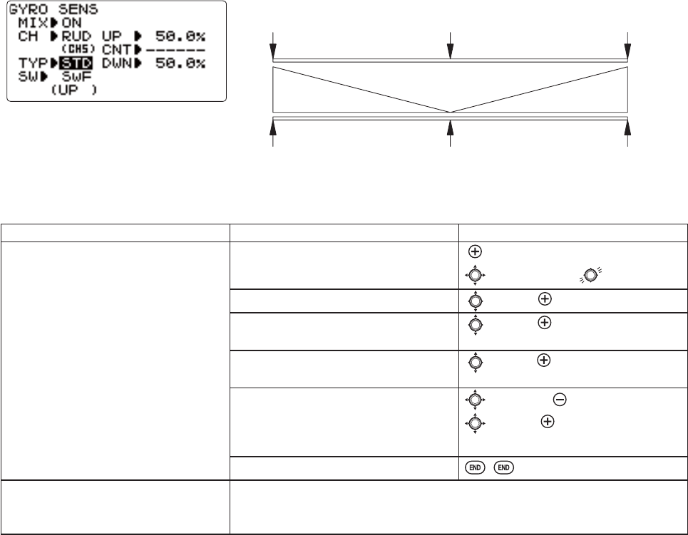
88
Gain Example for AVCS/Heading-hold Gyros (GY)
GOAL of EXAMPLE: STEPS: INPUTS:
6HWXSDKHDGLQJKROG$9&6 J\UR ZLWK
KHDGLQJKROG$9&6 VHWWLQJ LQ LGOHXSV
DQGDQGQRUPDOPRGHVHWWLQJLQLGOH
up 3 and normal.
Open and activate the GYRO SENSE
function.
for 1 second.
to GYRO SENSE.
Activate the function. to MIX. to ON.
2SWLRQDOFKDQJHJ\URW\SHWR+HDGLQJ
hold (GY
to TYP. to GY.
2SWLRQDOFKDQJHVZLWFK DVVLJQPHQW
Ex: select Cond
to SW. to Cond.
Adjust gyro rates as needed.
(Ex: NORM,IDL3 to NOR 50%.IDL1 and 2
to AVC 50% as starting points.)
to NORM. to NOR 50%.
to IDL1. to AVC 50%.
Repeat.
Close the function.
Where next? GOVERNOR: see p. 89.
D/R,EXP: see p. 39.
DELAY: see p. 84.
50%0% +100%
"Heading Hold Mode"
"Normal Mode"
CVA %001%0RON %001
GY
STD
/DUJHUSHUFHQWDJHVLQGLFDWHPRUHJDLQRUJ\URUHVSRQVLYHQHVV
7DLOZDJJLQJRUVKDNLQJLQGLFDWHVH[FHVVLYHJDLQVHWWLQJV7XUQGRZQJ\URVHWWLQJXQWLOZDJVWRSV
D[HVRID[HVRIVHWXSRIJ\URFDQEHFKRVHQE\CH.
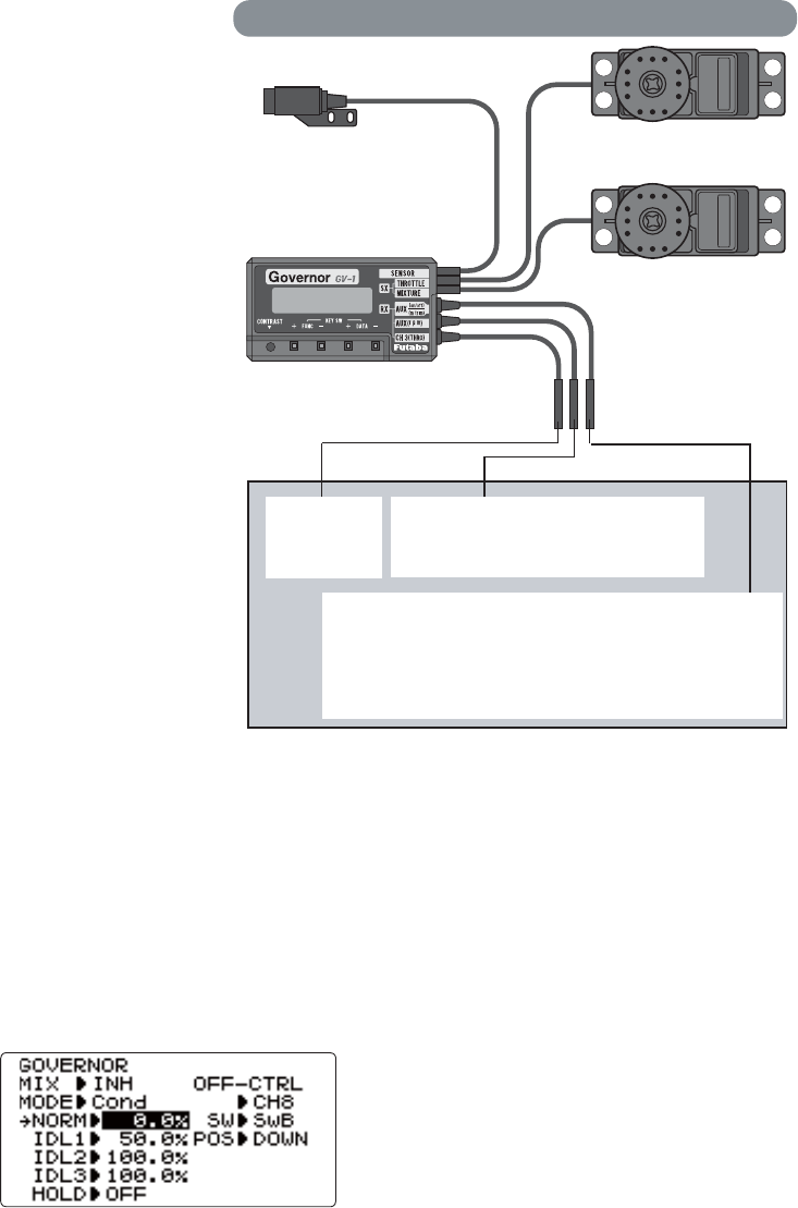
89
GOVERNORS:
:KDW LV D JRYHUQRU"$ JRYHUQRU LV PDGH XS RI D VHW RI VHQVRUV ZKLFK UHDG WKH 530 RI WKH KHOLFRSWHU¶V KHDG DQG D
control unit that automatically adjusts the throttle setting to maintain a constant head speed regardless of changes in pitch
of blades, weather conditions, etc. Governors are extremely popular in competition helicopters due to the consistency
provided.
+RZGRHVLWKHOSLQKHOLFRSWHUVHWXS"7KHJRYHUQRUHOLPLQDWHVWKHQHHGWRVSHQGODUJHDPRXQWVRIWLPHVHWWLQJXSWKURWWOH
FXUYHVDVLWDXWRPDWLFDOO\DGMXVWVWKHHQJLQH¶V530WRPDLQWDLQWKHGHVLUHGKHDGVSHHG
GOVERNOR 7KH *RYHUQRU PL[LQJ IXQFWLRQ LV XVHG WR DGMXVW WKH *9*<&*< *RYHUQRU VSHHG VHWWLQJV U6
U6U6IURPWKHWUDQVPLWWHU,I\RXDUHXVLQJDGLIIHUHQWJRYHUQRUIROORZWKHPDQXIDFWXUHUVLQVWUXFWLRQV
Adjustability:
2QRIIPD\EHVHSDUDWHGIURPURWRUVSHHGE\SOXJJLQJWKHJRYHUQRURQRIILQWR
FKDQGFKDQJLQJ&87&+VHWWLQJ
,I XVLQJ VHSDUDWH RQRII VZLWFK DVVLJQPHQW LV WRWDOO\ DGMXVWDEOH %H FDUHIXO
not to assign governor off to a condition switch if you want the governor to
function in that condition.
6SHHGVZLWFKLQJDQGJRYHUQRU212))PD\EHWRJHWKHUXVLQJRQHVZLWFKRU
212))VZLWFKLQJPD\EHSHUIRUPHGXVLQJDQLQGHSHQGHQWVZLWFKFKDQQHO
,QÀLJKWDGMXVWPHQWRIWKHKHDGVSHHGIRUHDV\DGMXVWPHQWGXULQJWXQLQJPD\
be created using an additional channel and a programmable mix. See www.
IXWDEDUFFRP?IDT?IRUGHWDLOV
GV-1 connections
Magnetic sensor
Throttle servo
Control amp
Mixture servo
Connected only when
fuel mixture function
used.
Throttle
channel
Speed setting channel
Connected when speed set from
transmitter
Governor ON/OFF / Mixture trim channel
Connected when the governor is turned on and off
from transmitter and when mixture trim function is
used, or when mixture curve data is sent from transmit-
ter to governor
Receiver
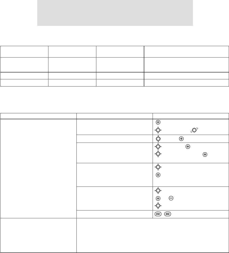
90
7KHJRYHUQRUFRQWUROVWKURWWOHZKHQLWLVDFWLYHVRWKHWKURWWOHZLOOQRWREH\DQ\)DLO6DIHVHWWLQJSUHVHWVIRUWKURWWOH
LQWKHWUDQVPLWWHU$OZD\VVHWWKH)DLO6DIHVHWWLQJIRUWKHJRYHUQRU¶VRQRIIFKDQQHOWR2))7KLVZD\WKHJRYHUQRULV
VKXWRIIDQGWKHWKURWWOHREH\VWKH)DLO6DIHWKURWWOHFRPPDQGV
Expert Tip: Mounting the governor to the counter gear instead of the fan
GUDPDWLFDOO\VLPSOL¿HVLQVWDOODWLRQLQPDQ\PRGHOV
)XWDEDVBPS-1 RPM Sensor which attaches a sensor to an exclusive engine
directly is simpler.
6HWWLQJH[DPSOH:KHQVSHHGDQG212))DUHXVLQJRQHVZLWFK
Governor Speed Switch Position
(Switch CRU&RQG Rate (%) $GMXVWPHQWIURP7[
562)) UP or NORM 0 8VHXSWR
*RYHUQRUVSHHGGLVSOD\UHDGV³RII´
RS2: 1400 CNTR or IDL1 50 Speed adjusted by raising and lowering rate.
RS3: 1700 DOWN or IDL2 100 Speed adjusted by lowering rate.
*The relationship of the governor speed setting rS1~rS3 and the switch positions conforms to the table above.
,QWKURWWOHKROGDOZD\VFKHFNWKDWWKHJRYHUQRULVRII
*If the speed value rises when the cut switch is activated, reverse the “DIR´VHWWLQJIURPUP to DOWN or vice versa.
GOAL of EXAMPLE: STEPS: INPUTS:
6HWXSD*9JRYHUQRUWRXVH
both channels into the receiver
and switch between the governor
settings automatically when changing
conditions. Consider setting the battery
)DLO6DIHVHWWLQJVDQGRWKHUKHOSIXO
IXQFWLRQVRQWKH*9LWVHOI
Open and activate the GOVERNOR
function.
for 1 second.
to GOVERNOR.
Activate the function. to MIX. to CH7.
2SWLRQDOFKDQJHFXWRIIFKDQQHO
WRFKDQQHODQGDVVLJQVZLWFKDQG
GLUHFWLRQIRURQRIIFKDQQHO
WRFXWMIX to CH7.
WR2))&75/SW.to desired
SWITCH.
2SWLRQDO FKDQJH VZLWFK DVVLJQPHQW WR
VHOHFWJRYHUQRUVHWWLQJV
Ex: select switch that adjusts the
FRQGLWLRQV
to MODE.
to Cond.
Adjust governor speed settings per
switch position or condition as needed.
(Ex: defaults are fine.) Allows head
speed adjustment from transmitter.
to each Cond position.
or as needed.
to next Cond position. Repeat.
Close the function.
Where next? GYRO: see p. 87.
$GMXVW)DLO6DIHF/S) settings (p. 48).
$GMXVWLGOHXSFROOHFWLYHSLWFKFXUYHIRUVDPHUDWHVRIFOLPEXSULJKWLQYHUWHG
See p. 78.
Adjust elevator/aileron response to fit your flying style: see D/R,EXP and END
POINT/SWASH AFR: p. 39, 36, 75.
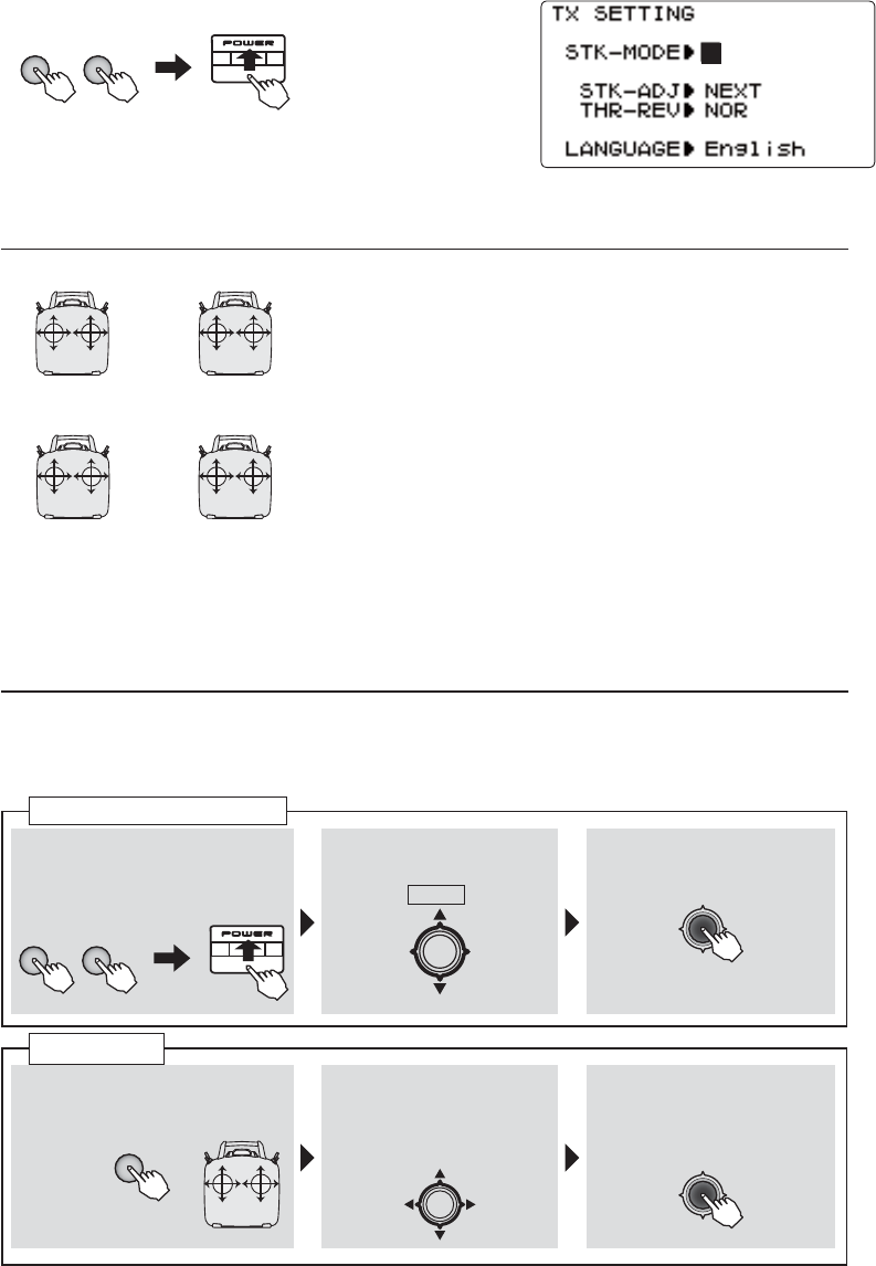
91
TX SETTING
7KLVLVQRWXVXDOO\XVHG3OHDVHGRQRWXVHXQOHVVQHFHVVDU\
7KLVVHWXSFDQEHSHUIRUPHGLQ6WLFN0RGH6WLFN$'-FDOLEUDWLRQ7KURWWOHVWLFNUHYHUVHDQG/DQJXDJH
■ STK-MODE
■ STK-ADJ (calibration)
The transmitter may be operated in four different
VWLFN³PRGHV´DQG7KHPRGHVGHWHUPLQH
WKHIXQFWLRQVWKDWZLOOEHRSHUDWHGE\FRQWUROVWLFNV
&XUUHQWO\ WKH WUDQVPLWWHU LV LQ ³0RGH ´ DQG VKRXOG EH
OHIW LQ 0RGH XQOHVV \RX DUH DQ H[SHULHQFHG À\HU DQG
KDYHOHDUQHG WR À\ LQ DGLIIHUHQWPRGH ,Q PRGH WKH
ULJKW FRQWURO VWLFN RSHUDWHV WKH DLOHURQ DQG HOHYDWRU DQG
WKHOHIWVWLFNRSHUDWHVWKHUXGGHUDQGWKURWWOH7KLVLVKRZ
RI$PHULFDQVÀ\WKHLUPRGHOV
The mode can be chosen by +− KEY from "STK-
MODE" of the TX SETTING screen. The throttle detent
mechanism will have to be moved as well. This can be
GRQHE\WKH)XWDED6HUYLFH&HQWHU
Usually, this calibration is unnecessary.
3OHDVHSHUIRUPWKLVFDOLEUDWLRQRQO\LI DFKDQJHDWWKHFHQWHU RIDVWLFNVKRXOGDULVHDIWHU
prolonged use.
THRELE
RUD AIL
MODE 1
ELETHR
RUD AIL
MODE 2
THRELE
AIL RUD
MODE 3
ELETHR
AIL RUD
MODE 4
① Simultaneously depress the
+ and −keys, and then turn
on the power.
②It is down about -2*
KEY. It chooses STK-
ADJ > NEXT
③-2*.(< is pushed.
The call of a setting screen
+ −
+ −
① 6WLFN RI WR LV FKRVHQ E\
+− Keys.
+
② It is down about -2*
KEY. It is set to
ADJ > NEUT ■
③ $VWLFNLVPDGHQHXWUDO
and -2*.(< is
pushed.
calibration
23
41
1.Simultaneously depress the + and −NH\VDQGWKHQWXUQRQWKHSRZHU
7;6(77,1*,WLVGLVSOD\HG
․
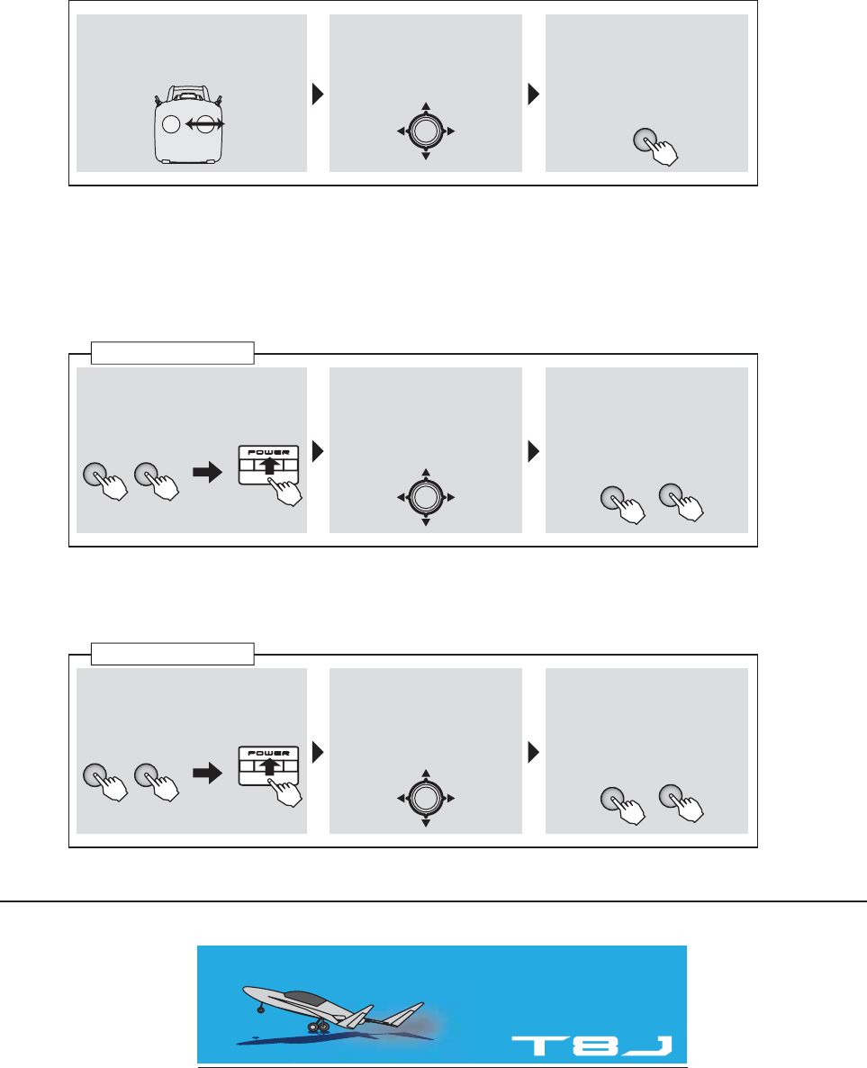
92
■ THR-REV
■ LANGUAGE
8VXDOO\WKLV7+55(9LVXQQHFHVVDU\,WLVXVHGZKHQ\RXGHVLUHWKURWWOHVWLFNRSHUDWLRQ
FRQWUDU\WRXVXDOVWLFNLVWKHERWWRPĺHQJLQHKLJKVWLFNLVWKHWRSĺ,GOLQJ
※5HYHUVDO RI WKH WKURWWOH VHUYR LQ OLQNDJH LV XVXDOO\ SHUIRUPHG E\ UHYHUVH RI D PHQX
:KHQWKLV7+55(9LVXVHGLWLVVORZDQGDWULPVWRS
The language displayed can be chosen from seven languages.
,WLVWKHUHERRWRIDSRZHUVXSSO\ZKLFKLVUHWXUQHGWRDQRUPDOVFUHHQIURP7;6(77,1*
④ $ VWLFN LV IXOO RSHUDWHG ULJKW
and left (up and down).
⑤■is displayed beside
/()7DQG5*+783
DOWN). -2*.(< is
pushed.
⑥ It is the display of
"Complete" and is END.
END
① Simultaneously depress the
+ and −keys, and then turn
on the power.
② It is down about -2*
KEY. It chooses THR-
REV > NOR
③ &KRRVH LQ 125 RU 5(9
by +− KEY.
It completes with the
SRZHUVXSSO\2))
① Simultaneously depress the
+ and −keys, and then turn
on the power.
② It is down about -2*
KEY. It chooses LAN-
GUAGE > English
③ Choose in language by
+− KEY.
It completes with the
SRZHUVXSSO\2))
THR-REV setting
THR-REV setting
+ −
+ −
+
+
−
−
)87$%$&25325$7,21
<DEXWVXND&KRVHLPXUD&KRVHLJXQ&KLEDNHQ-DSDQ
3KRQH)DFVLPLOH
2012, 2 (1)
93