G G Telecom MLIVE Surveillance Camera User Manual
G.G.Telecom Surveillance Camera Users Manual
Users Manual
Quick start guide
Cellular trail
camera
Models:
Mini-LIVE
Mini-LIVE-4G
Mini-LIVE-4GV
Mini-LIVE-CV
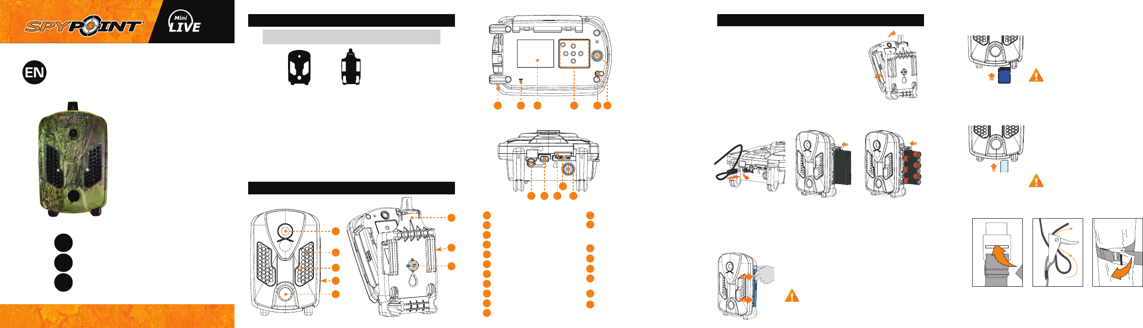
In the box
1
2
3
5
4
Components
Note: Memory card and batteries are sold separately.
* Mini-LIVE and Mini-LIVE-4G only
Included for United States, Canada and United Kingdom only
Navigation buttons
Microphone
(Mini-LIVE-4G,
Mini-LIVE-4GV and Mini-LIVE-
CV)
Power button
12V/Solar panel jack
USB port
SIM card slot (Mini-LIVE and
Mini-LIVE-4G)
SD card slot
Built-in speaker (Mini-LIVE-4G,
Mini-LIVE-4GV and Mini-LIVE-
CV)
Photo lens
Invisible LEDs
Test light
Battery case
Detection lens
Mounting bracket
Slot for installation strap
Tripod mount
Cable lock hole
BUSY LED
Viewing screen
1
2
3
4
5
6
7
8
9
10
11
12
910 11 12 13 14
13
14
15 17 1916
18
15
16
17
18
19
3. INSERT THE MEMORY CARD
Insert an SD/SDHC memory card (up to 32
GB capacity) in the card slot, gold contacts
facing up. The card is inserted correctly
when a click is heard.
Before inserting or removing a memory
card, always turn off the camera to
prevent loss or damage of the photos already
recorded.
4. INSERT THE SIM CARD (MINI-LIVE AND MINI-LIVE-4G)
A SIM card is required to use cellular
functions. Carefully insert a SIM card in the
card slot, gold contact area facing down.
The card is inserted correctly when a click
is heard.
Before inserting or removing a SIM
card, always turn off the camera.
5. INSTALL THE CAMERA WITH THE SUPPLIED STRAP
Recommended installation height: about 3 feet above the ground.
Do not place the camera facing the sun.
1. Insérez l’extrémité de la courroie dans la fente
qui se trouve au dos du mécanisme. 2. Insérez la courroie dans la fente sous le levier
et faites-la ressortir en arrière. 3. Créer une tension sur la courroie en la tirant vers
la droite, puis rabattez vers la gauche le levier pour
maintenir la position.
1. REMOVE CAMERA FROM THE
MOUNTING BRACKET
A. Push the tab to release the camera from
the mounting bracket.
B. Remove the camera.
2. CHOOSE A POWER SOURCE
In order to get best results and longer battery life, we recommend
the use of an external 12V source. For easier access to the 12V jack,
remove the camera from the mounting bracket before plugging a 12V
cable. Then, the camera can be reinstalled in the mounting bracket.
Rechargeable AA batteries are not recommended.
Getting started
6
8
7
A.
B.
• Lithium battery pack
LIT-09/LIT-C-8 • 6 alkaline AA
batteries
• 12V power source
v1.4
1-888-779-7646
support.spypoint.com
tech@spypoint.com
Installation
strap USB
cable
Camera Quick start
guide
SIM card*
Mounting
bracket
2
1
Using your ngers, push down on each side of
the battery compartment's tab to open it.
The battery compartment adapts to
SPYPOINT LIT-09 lithium battery pack or
6 AA alkaline batteries. Therefore, it is important
to be careful while inserting AA batteries.
E. Set the Transmission mode option (Mini-LIVE only)
• MySPYPOINT: The camera communicates with the
mySPYPOINT server to update its status or to send photos
to the user account.
MySPYPOINT subscription is required. Activation
procedure available at support.spypoint.com/
activation.
• MMS: The camera communicates by MMS to
update its status or to send photos. Enter up to 5 different
phone numbers to which the MMS will be sent. The country
code and area code must be entered. One MMS is charged
for each recipient.
A MMS plan is required, available from a compatible
cellular service provider. Activation procedure
available at support.spypoint.com/activation.
• Email: The camera communicates by email to
update its status or to send photos. Enter up to 5 different
email addresses to which notications will be sent.
A data plan is required, available from a cellular
service provider. Activation procedure available at
support.spypoint.com/activation.
F. Set the Frequency option. Allows the user to choose the
number of synchronizations that the camera performs in a
day.
G. Set the First synch time option. Allows the user to choose at
what time of the day the camera communicates for the rst
time.
E.g.: If the "Frequency" option is set to 6/day and "First synch
time" at 04:00, the camera performs 6 synchronizations per
day and rst starts sending at 4 h, 8 h, 12 h, 16 h, 20 h and
24 h.
2. CONFIGURE THE WIRELESS SETTINGS
A. In the main menu, select SETTINGS and then, WIRELESS to
access the Wireless settings menu.
B. Set the Cellular option. Activate this option to send photos by
cellular transmission.
Activation procedure available at
support.spypoint.com/activation
For Mini-LIVE-4GV and Mini-LIVE-CV camera, go directly
to F step.
C. Set the Country option. The country where the camera is
used must be selected.
D. Set the Provider option. The provider selected must
correspond with the SIM card used in the camera.
For Mini-LIVE-4G camera, go directly to F step.
Power source LIT-09 charger option
• 6 AA
• 12V
• 12V + 6 AA OFF
• LIT-09*
• 12V + LIT-09*
• Solar panel + LIT-09*ON
* Rechargeable lithium battery pack, sold separately (LIT-09)
or with a charger (LIT-C-8).
Use the h and buttons to navigate in the interface and to change
options. Use the OK button to conrm and the button to return to
the previous menu.
1. CONFIGURE THE GENERAL SETTINGS
A. Turn on the camera by pressing the power button.
B. In the main menu, select SETTINGS and then GENERAL to
access to the General settings menu.
C. Set the Date format (MM/DD/YY or DD/MM/YY) and the Date.
D. Set the Time format (12H/24H) and the Time (Hour/Minute).
E. Set the Schedule option. This option allows the user to set
the period of operation of the camera for each day of the week.
For a 24 hour operation, the same start and stop times must be
entered as followed (e.g.: 00:00/00:00).
F. Set the LIT-09 charger option depending on the power
source (see next table).
Settings PERFORM THE STEPS 4 TO 6 DURING THE FINAL
INSTALLATION OF THE CAMERA.
4. TEST THE DETECTION OF THE CAMERA
When the TEST mode is selected,
no photo or video is recorded. Pass
in front of the camera from left to
right. When the camera detects
motion, the test light blinks to
indicate that the camera would
normally have saved a photo
or video. If the system does not
detect the movement, increase
the detection sensitivity using the
SENSITIVITY option in the GENERAL SETTINGS menu or realign
the system differently. In TEST mode, it is possible to take a
photo by pressing the OK button. The photo is saved and appears
in the VIEW mode.
6. START THE CAMERA
Select the desired operating mode
(photo, time lapse or video) on the
main menu by pressing OK. When
the mode is selected, the test light
in front of the camera will ash
for 60 seconds to allow the user
to leave the area without being
photographed or recorded.
FACEBOOK.COM/SPYPOINT TWITTER.COM/SPYPOINTCAMERA YOUTUBE.COM/SPYPOINTTRAILCAM
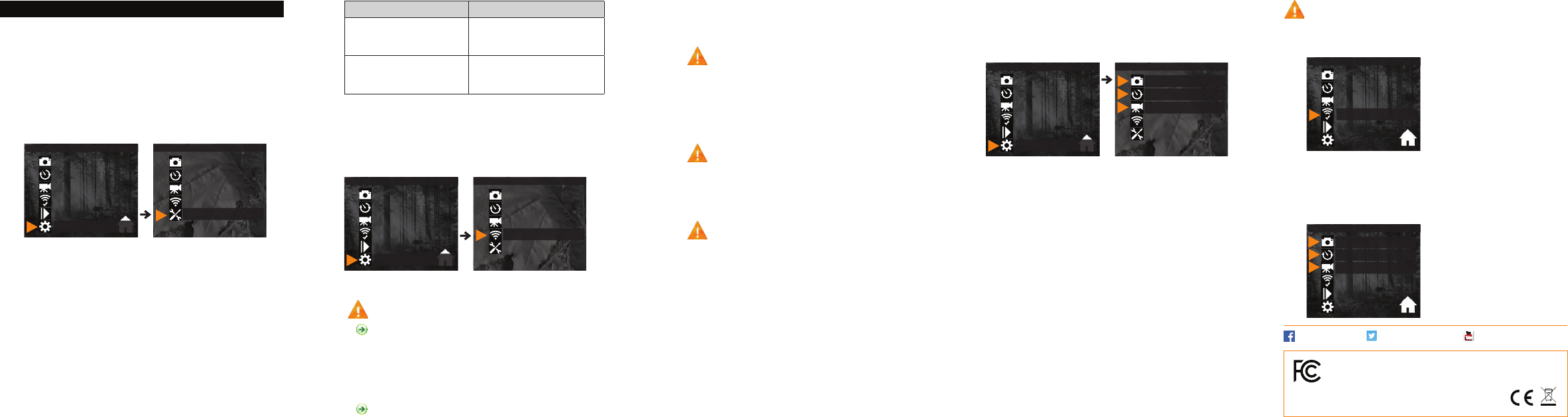
3. CONFIGURE THE SETTINGS OF THE 3 OPERATING MODES
In the main menu, select SETTINGS and then, PHOTO, TIME
LAPSE or VIDEO to access to the respective operating mode
menu.
PHOTO
Delay: Allows the user to choose the time interval between each
detection before the camera can record the next photo.
Multi-shot: Takes up to 6 consecutive shots at each detection,
with a 10 second delay between each photo.
TIME LAPSE
Interval: This option allows the camera to take photos at regular
preset intervals without detection.
VIDEO
Delay: Allows the user to choose the time interval between each
detection before the camera can record the next video.
Video lenght: Allows the user to select the duration of the
recording.
Photo rst: When this option is enabled, a photo is taken
immediately before each video.
(Conguration)
Photo
(Conguration)
Time lapse
(Conguration)
Vidéo
(Conguration)
Photo
(Conguration)
Time lapse
(Conguration)
Vidéo
(Conguration)
Général
HOME
SETTINGS
Photo
Time lapse
Video
Test
View
Settings
Photo
Time lapse
Video
Wireless
General
(Conguration)
Sans l
(Conguration)
Photo
(Conguration)
Time lapse
(Conguration)
Vidéo
(Conguration)
Photo
(Conguration)
Time lapse
(Conguration)
Vidéo
(Conguration)
Général
HOME
SETTINGS
Photo
Time lapse
Video
Test
View
Settings
Photo
Time lapse
Video
Wireless
General
(Conguration)
Sans l
(Conguration)
Photo
(Conguration)
Time lapse
(Conguration)
Vidéo
(Conguration)
Photo
(Conguration)
Time lapse
(Conguration)
Vidéo
(Conguration)
Général
HOME
SETTINGS
Photo
Time lapse
Video
Test
View
Settings
Photo
Time lapse
Video
Wireless
General
(Conguration)
Sans l
(Conguration)
Photo
(Conguration)
Time lapse
(Conguration)
Vidéo
HOME
Photo
Time lapse
Video
Test
View
Settings
(Conguration)
Photo
(Conguration)
Time lapse
(Conguration)
Vidéo
HOME
Photo
Time lapse
Video
Test
View
Settings
This device complies with Part 15 of the FCC rules. Operation
is subject to the following two conditions: (1) this device
may not cause harmful interference, and (2) this device must
accept any interference received, including interference
that may cause undesired operation. FCC ID: EEX-MLIVE