G I T G1NDDMN002 Vehicle scan tool User Manual GDS
G.I.T Co.,Ltd. Vehicle scan tool GDS
UserManual.wiki
>
G I T
>
G1NDDMN002 User Manual
User Manual
Navigation menu
Upload a User Manual
Namespaces
Wiki Guide
HTML
PDF
Info
Views
User Manual
Discussion / Help
Navigation
![7 Start of Vehicle Diagnostic Functions G3180203 When using the vehicle diagnostic functions of G-scan3, select [Diagnosis] on the initial window. Then a window will be displayed for selecting an automaker. Select the maker that matches the vehicle to be diagnosed. The structure of the diagnostic functions available on the main window of G-scan3 is as follows. Read the descriptions of the functions before using them. No. Icon Function Name Description 1 FCS This enables scanning of the diagnostic trouble codes (DTCs) that are saved for all the systems of a vehicle that support diagnostic communications. 2 DTC Analysis This enables scanning of the DTCs that are saved for a single selected system, and displays the trouble information of a vehicle. 3 Data Analysis This enables communication with a single selected system, and displays the status value of sensor items. 4 Multi Data Analysis This applies only to CAN communications systems. It establishes communications with multiple systems, and displays the status value of sensor items. 5 Actuation Test This enables checking of normal operation by forcibly driving or stopping the actuators mounted on a vehicle. 6 System Identification This displays the identification of the systems mounted on a vehicle. 7 S/W Management This enables additional setting, inspection, initialization, etc., after maintenance of a vehicle.](https://usermanual.wiki/G-I-T/G1NDDMN002/User-Guide-3787251-Page-8.png)
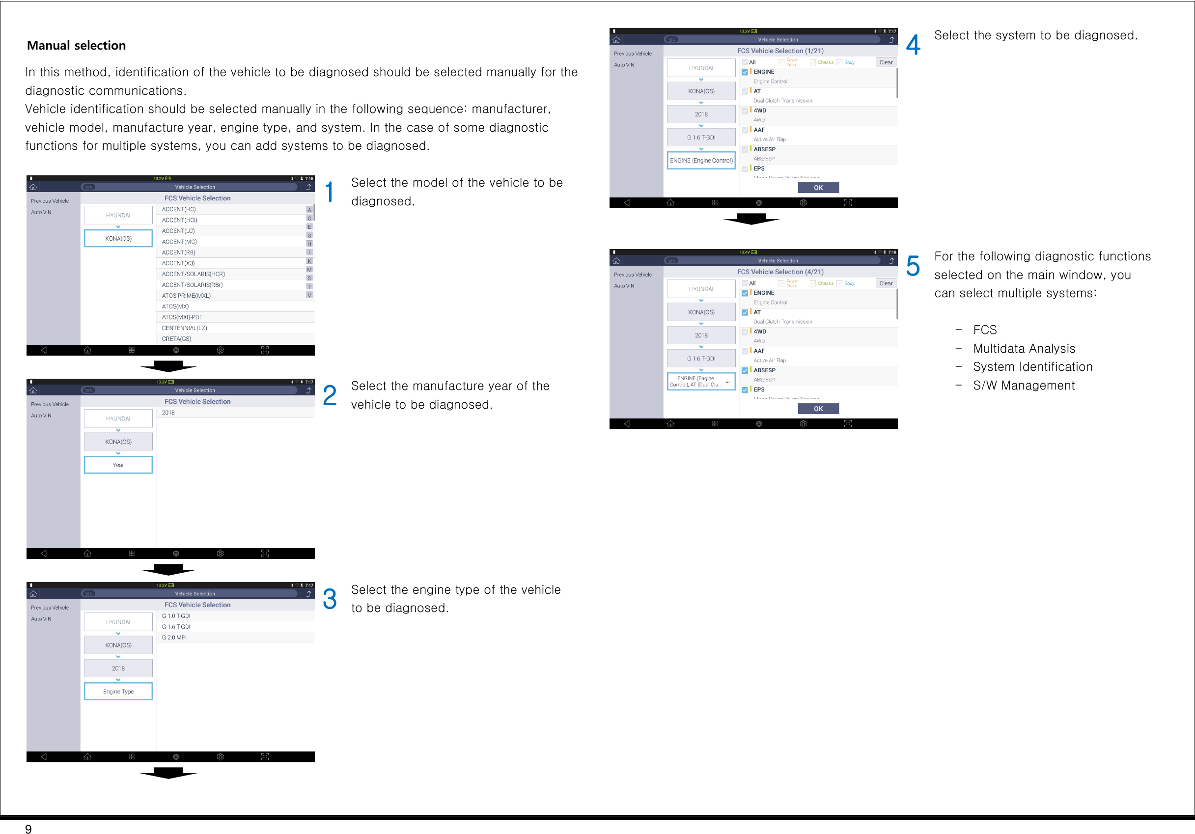
![8 Vehicle Model Selection G3180203 This is the stage where a vehicle model to be diagnosed is selected. A vehicle model can be selected by the "Auto VIN" or the manual selection method. Auto VIN: This method reads the vehicle identification number (VIN) from the ECU of the vehicle, and selects the VIN automatically. Manual selection: In this method, vehicle identification should be selected manually in the following sequence: manufacturer, vehicle model, manufacture year, engine type, and system. Auto VIN This method reads the vehicle identification number (VIN) from the ECU of the vehicle, and selects the VIN automatically. 1 Click [Auto VIN] in the left button tab. 2 Communication with the vehicle will be established, and the VIN will be read. 3 The model, manufacture year, and engine specifications will be selected automatically, and the VIN will be displayed at the top of the diagnostic program. Note: When no VIN can be read in the "Auto VIN" mode, the following VIN input popup window will be displayed: Enter the 17-digit (numbers + alphabets) code of the vehicle and click the [OK] button, and the vehicle selection will be completed automatically.](https://usermanual.wiki/G-I-T/G1NDDMN002/User-Guide-3787251-Page-9.png)
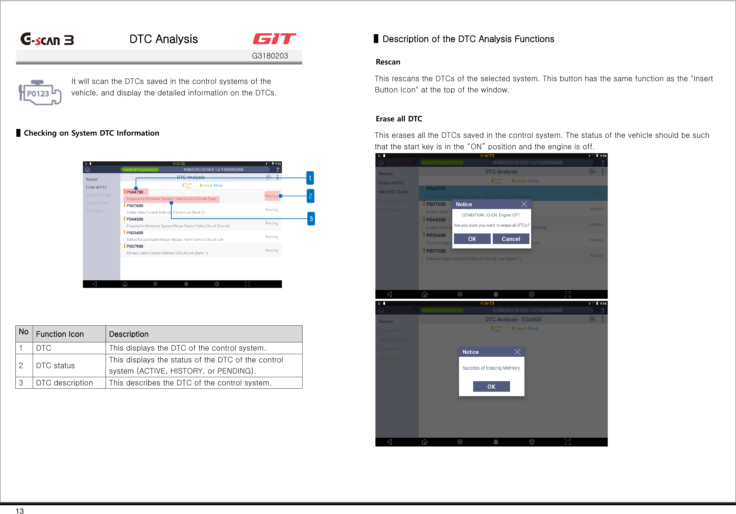
![11 DTC Analysis On the "All DTC” scanning window, after a system is selected, clicking of the [DTC Analysis] button will change the window to the one for the DTC analysis functions. * For the method that uses the DTC analysis functions, see [DTC Analysis]. Sensor data Analysis On the "All DTC" scanning window, after a system is selected, clicking the [Sensor data Analysis] button will change the window to the one for the sensor data analysis functions. * For the method that uses the sensor data analysis functions, see [Sensor data Analysis].](https://usermanual.wiki/G-I-T/G1NDDMN002/User-Guide-3787251-Page-12.png)
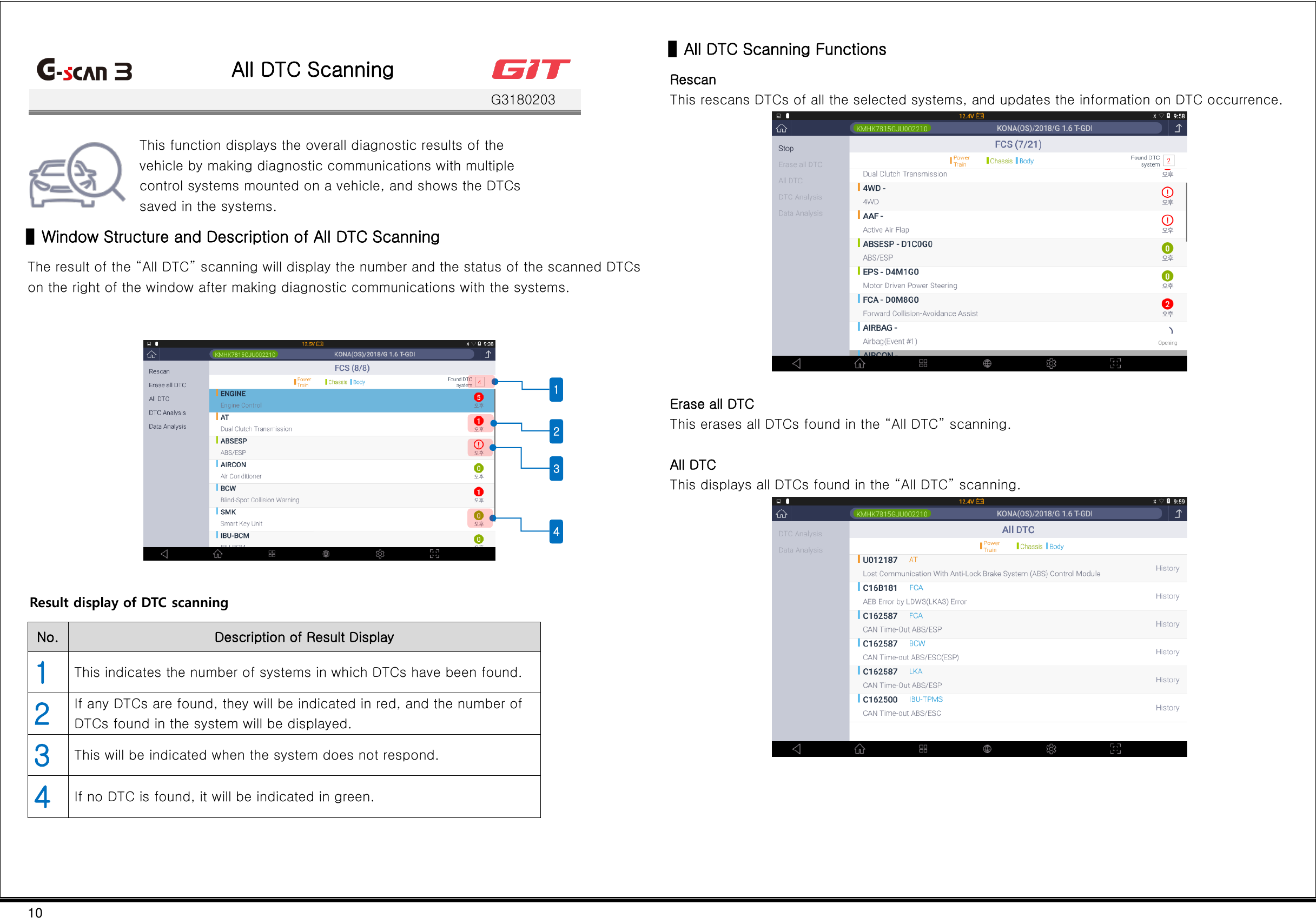
![12 ▌All DTC Scanning 1 Select the manufacturer, vehicle model, manufacture year, engine type, and system. Then click the [OK] button to start "All DTC" scanning. * FCS is one of the functions for which multiple systems can be selected. 2 It will scan the control systems sequentially. 3 It will display the DTC occurrence status of the control systems.](https://usermanual.wiki/G-I-T/G1NDDMN002/User-Guide-3787251-Page-13.png)
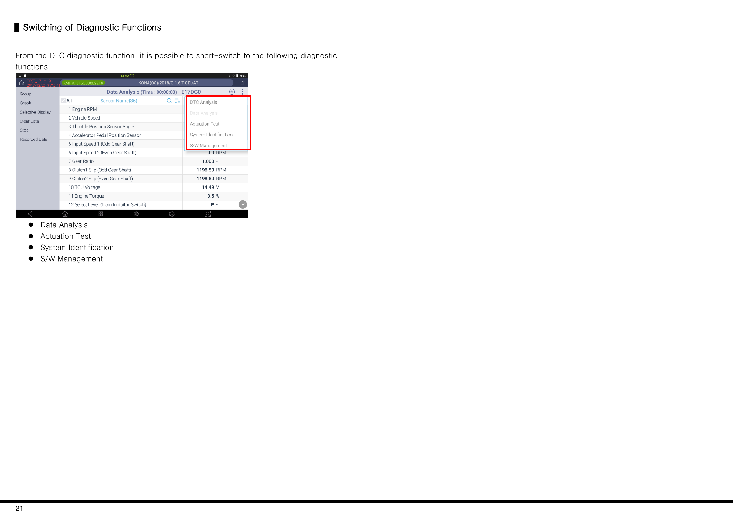
![14 Mini DTC Guide This provides a simple guide to the DTCs scanned in the DTC Analysis. Trouble status data This enables a query to the status value of the related sensor data items saved during DTC occurrence. * Clicking of the [Go back] button will change the window back to the DTC Analysis window. DTC status This shows a short description of the DTC, and its current status. ▌Switching of Diagnostic Functions While diagnostic communications between G-scan3 and the vehicles are established, you may switch to different diagnostic functions: Data Analysis Actuation Test System Identification S/W Management](https://usermanual.wiki/G-I-T/G1NDDMN002/User-Guide-3787251-Page-15.png)
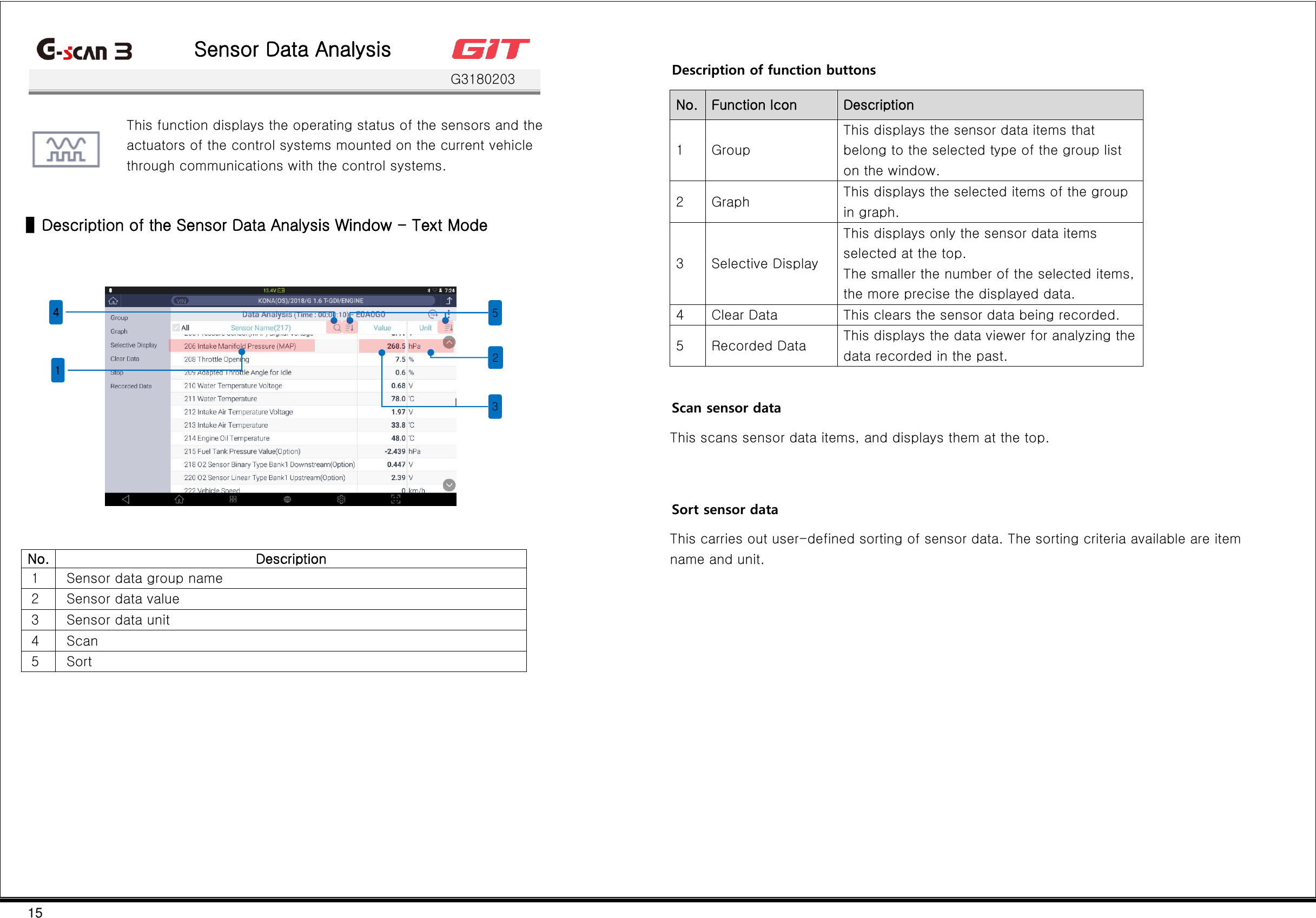
![16 Placement of sensor data You can place the necessary items selected among the ECM data under communication at the top. Fixation of sensor data items is a prerequisite when converting to the graphic mode. Method for fixating/clearing items Clicking of the sensor data items on the window will place them at the top, which are indicated in blue. Similarly, clicking of the sensor data items placed at the top will clear its placement from the said position. ▌Use of Groups Sensor data items are categorized according to group attributes, and it is possible to analyze data by categorizing sensor data into groups. 1 Click the [Group] button in the left list. 2 Click a group to be diagnosed among the list of the groups supported by the control systems. 3 Only the sensor data items defined for the selected group will be displayed on the window. To view all the groups in the list of the groups of sensor data items, click [All] for the group list.](https://usermanual.wiki/G-I-T/G1NDDMN002/User-Guide-3787251-Page-17.png)
![17 ▌Use of Graph Mode The graph mode displays the values of sensor data items in a graph so that the user may visually identify the changes in sensor data values. Viewing in graph mode 1 Select and place the sensor data items at the top. 2 After the sensor data items are selected, click the [Graph] button. 3 Then the sensor data items placed at the top will be displayed in a graph. ▌Selective Display This function displays only the sensor data items selected by the user to increase the accuracy of the sensor data display.](https://usermanual.wiki/G-I-T/G1NDDMN002/User-Guide-3787251-Page-18.png)
![18 ▌ Description of the Sensor Data Analysis Window - Graph Mode Text This switches the window display from the graph mode to the text mode. Clear Data This clears the data collected through communications with the control systems of the vehicle, and restarts data collection. Stop This stops the process of collecting sensor data from the control systems of the vehicle. Recorded Data No. Function Icon Description 1 Text This switches the graph mode to the text mode. 2 Clear Data This clears the collected sensor data values, and restarts data recording. 3 Stop This stops sensor data recording. 4 Recorded Data This displays the recorded data. Description of the graph analysis function While sensor data are collected in the graph mode, clicking of the [Stop] button will switch the window to the data analysis mode. No. Function Icon Description 1 This enables activation of cursors A and B, and displays the time gap between Cursor A and Cursor B. 2 This indicates the playback position of the sensor data recording on a bar. 3 This indicates the playback position of the sensor data recording in the time unit. 4 This plays/stops sensor data records in the regular/reverse direction.](https://usermanual.wiki/G-I-T/G1NDDMN002/User-Guide-3787251-Page-19.png)
![19 To the left of the sensor data; No. Icon Description 1 This excludes the item from the list of graph display. 2 Maximum This indicates the maximum value on the current graph display window. 3 Minimum This indicates the minimum value on the current graph display window. 4 This enlarges the graph of the pertaining item to the maximum. However, it will not exceed the graph display area. Save data This saves the sensor data acquired in this the sensor data function in a file. The data can be retrieved with the "Stored Data Analysis" function. Save data 1 Click the [Stop] button to stop data reception. 2 When data reception is stopped, the "Data Analysis" window will appear as shown in the left figure. 3 Clicking of the [Save] button will prompt a window for designating the file saving path and inputting remarks. After inputting remarks, click the [OK] button.](https://usermanual.wiki/G-I-T/G1NDDMN002/User-Guide-3787251-Page-20.png)
![20 Retrieving of stored data In the graph mode, you can call the existing sensor data records, and compare them. At this time, the top part of the window will display sensor data values and the bottom part will display the saved data playback bar. 1 Click the [Recorded Data] button. 2 Go to the data saving path, find a file, and click the [Open] button. 3 Clicking of the [Save] button will prompt a window for designating the file saving path and inputting remarks. After inputting remarks, click the [OK] button. The sensor data will be stored in a file with *.GSR format, which can be rechecked at the [Data] function of the initial window, or [Recorded Data] in the “Sensor Data Analysis” function.](https://usermanual.wiki/G-I-T/G1NDDMN002/User-Guide-3787251-Page-21.png)
![22 Multi Data Analysis G3180203 This function enables concurrent communications with multiple ECMs, and displays sensor data items designated for multiple systems on the window. The [Multi Data Analysis] function supports only the ECM systems under diagnosis that use the CAN protocol. ▌Selection of Multiple Systems In Step 2 of the multisystem selection, sensor data items will be listed for the "Multi Supported System" in blue shade in the left column. Select a system, and then select sensor data items. 1 Select a control system to be subjected to diagnostic communications, and click the [OK] button. 2 When sensor data items of the control system are selected, they will be registered in the left list. 3 After selecting sensor data items of the control system to be registered as selected items, click the [OK] button to complete the sensor data item selection. ▌Multi Data Analysis In the "Multi Data Analysis" function, the listing of sensor items and sensor values is the same as that of the "Sensor Data Analysis" function. The system information of the sensor data items is listed on the left. The structure of the window and the method for using this function are the same as those of the "Sensor Data Analysis" function.](https://usermanual.wiki/G-I-T/G1NDDMN002/User-Guide-3787251-Page-23.png)
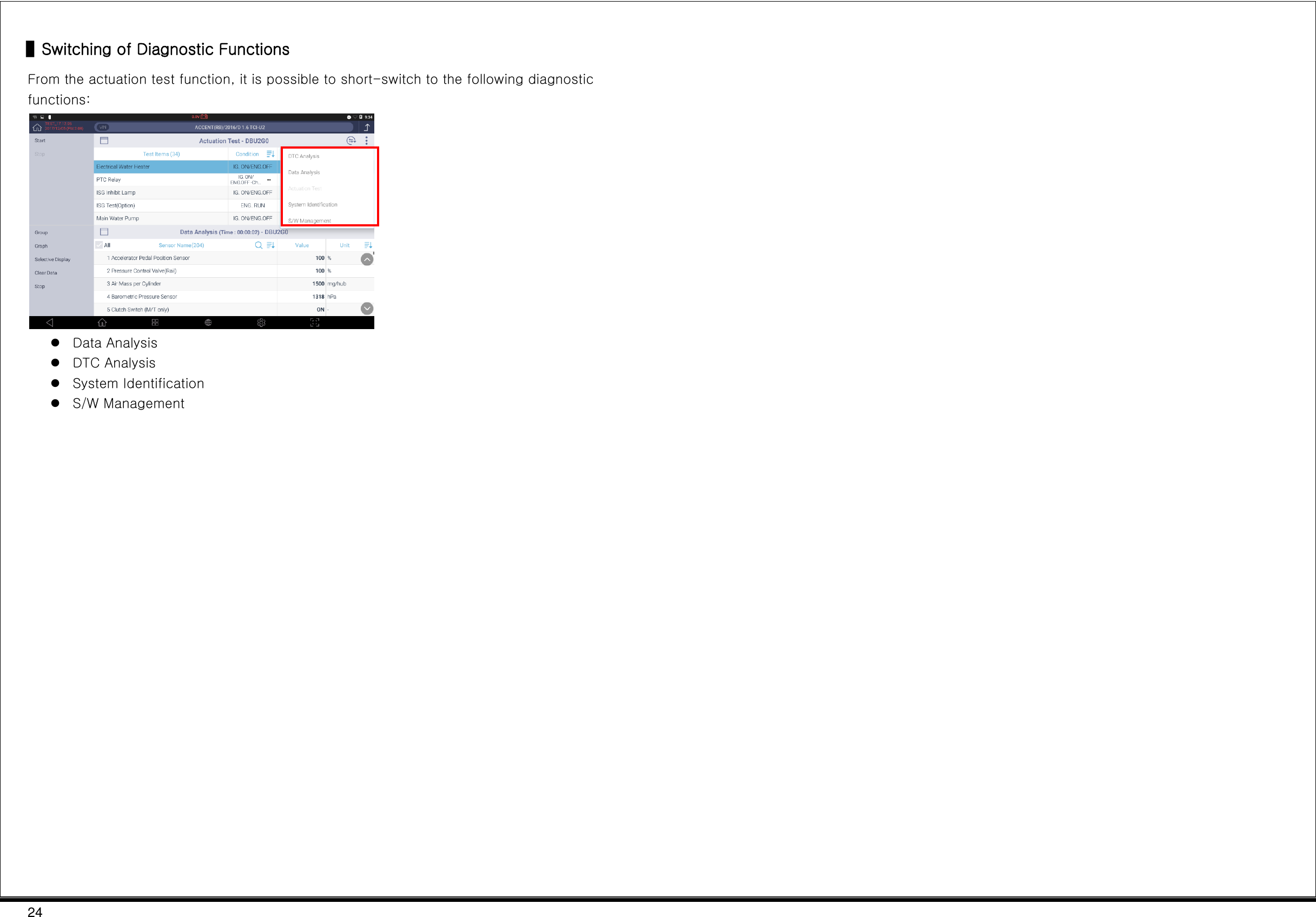
![23 Actuation test G3180203 This function drives the actuators of the systems of a vehicle by controlling the ECU of the vehicle with G-scan3, and enables checking the faults on the actuators. * The supported actuation test items may vary depending on the control systems of vehicles. The actuation test window comprises "Actuation Test" at the top and "Data Analysis" at the bottom. Its purpose is to identify changes in the related sensor items by forcibly operating actuators. A B Item Description A Actuation test Along with the actuation test items supported by the control systems of the vehicle, actuation “condition," "duration," and "result" are displayed. B Sensor data analysis The sensor data items supported by the control systems of the vehicle and their status values are displayed. ▌Use of Actuation Test 1 Select a control system to be subjected to diagnostic communications, and click the [OK] button. 2 Select the sensor data items related with the actuation test. To facilitate the reading, you may set the window in graphic mode. 3 After selecting an actuation test item, click the [Start] button at the upper-left part. * Depending on the actuation test items, you may stop the actuation by clicking the [Stop] button.](https://usermanual.wiki/G-I-T/G1NDDMN002/User-Guide-3787251-Page-24.png)
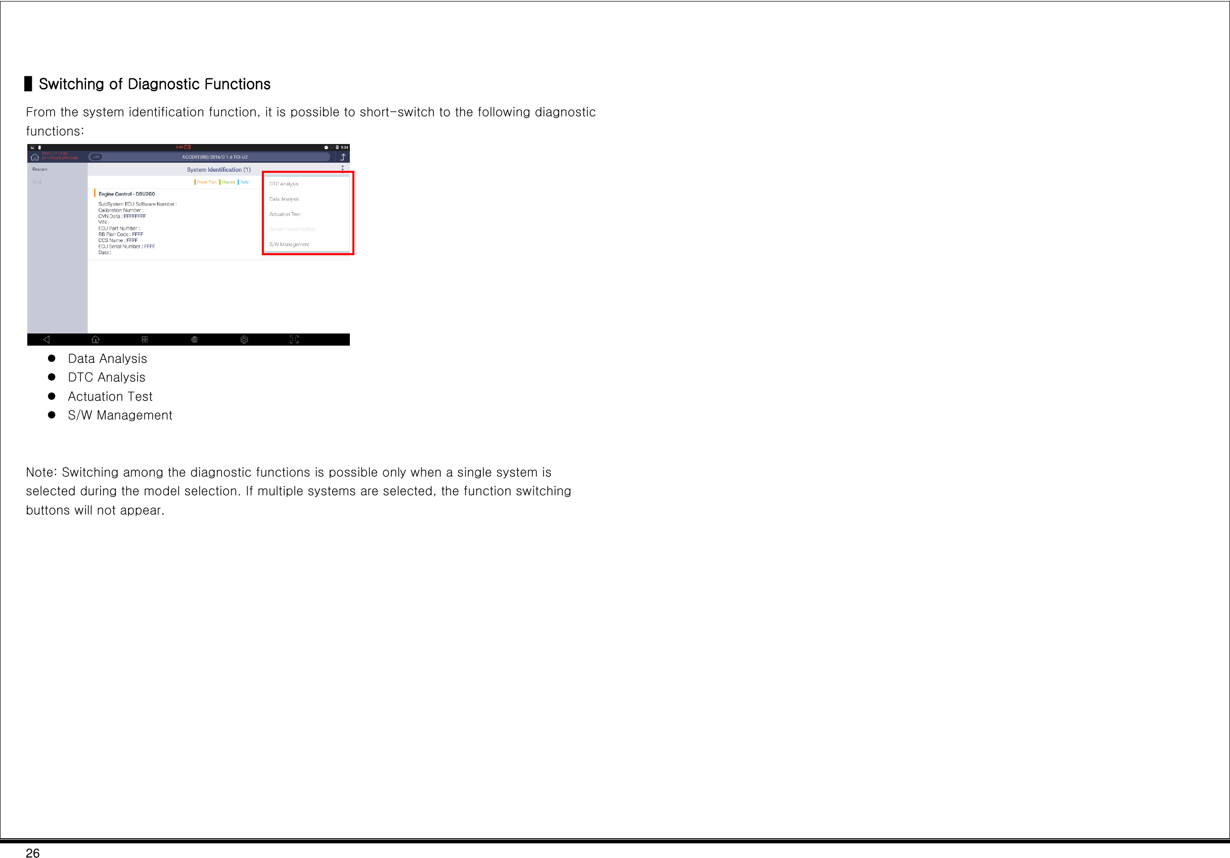
![25 System Identification G3180203 This function reads and displays the identification of the control systems mounted on a vehicle. The system identification function on the initial window enables selection and identification of multiple systems. Item Description Rescan This rescans identification of all the control systems selected during the vehicle selection. The rescanning will be done only for the control systems on which the "rescan" button is indicated. ▌Use of System Identification 1 Select all the control systems to be scanned in terms of system identification, and click the [OK] button. 2 The identification information on the control systems selected during the vehicle selection will be displayed on the window.](https://usermanual.wiki/G-I-T/G1NDDMN002/User-Guide-3787251-Page-26.png)
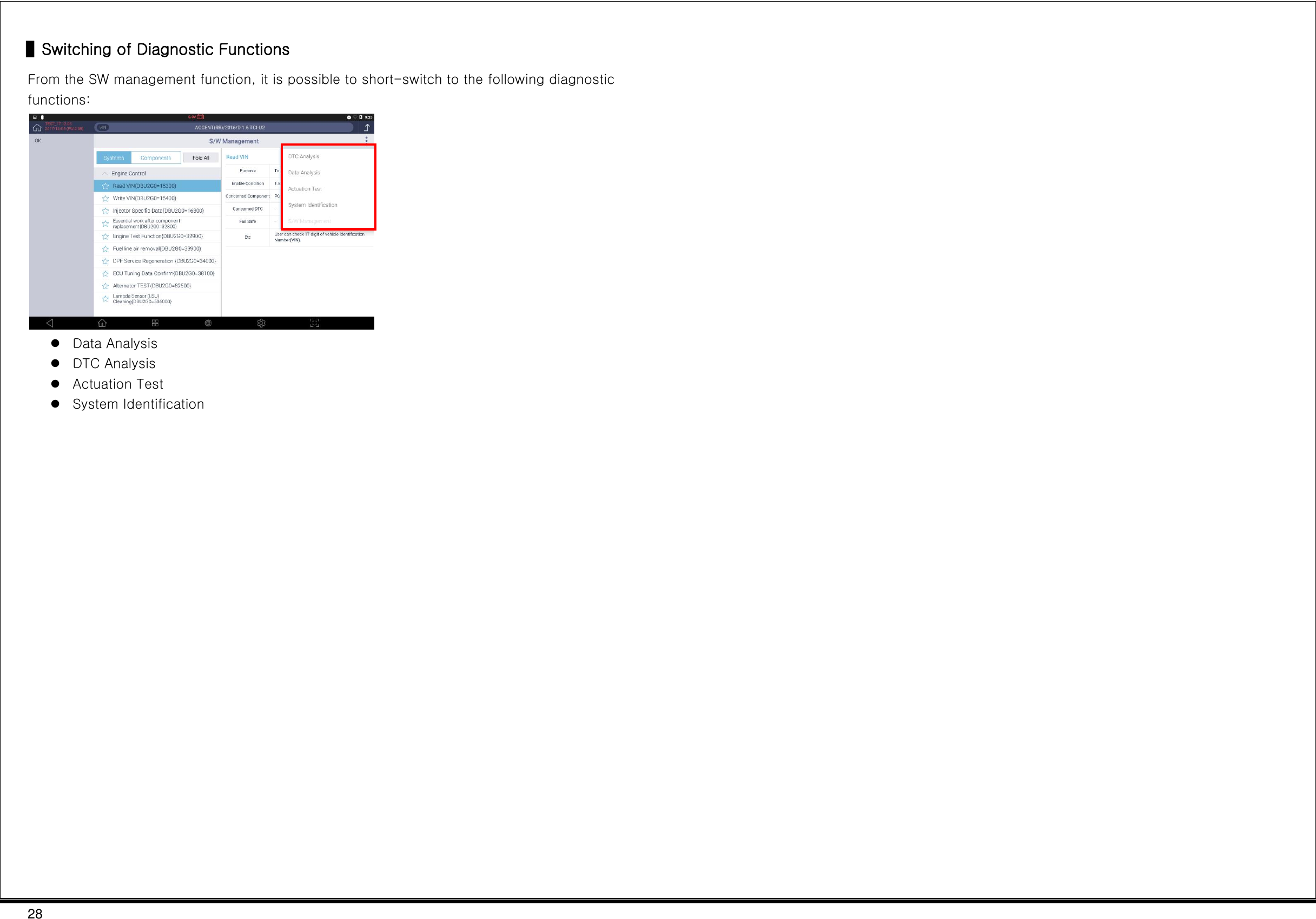
![27 Additional Functions G3180203 In addition to vehicular diagnostics, additional setting/testing functions are supported, including "learning value initialization," "immobilizer registration," and "injector data input" for the control systems of vehicles, as well as "tire pressure monitoring" and "evaporative gas leakage test." Item Description By system This displays the list of additional functions that support the control systems of the vehicle. By work category This displays the list of additional functions that support vehicle maintenance works. Open all This displays the full list of additional functions by system. Additional function execution window This enables execution of a selected additional function. ▌Use of Additional Functions 1 Select all the control systems to be scanned in terms of system identification, and click the [OK] button. 2 After selecting an additional work item at the lower part of the "By system" or "By work" tab, click the [OK] button at the upper-left part. * For the sake of safe work, make sure to read, before selecting a work item, the details relating to the additional function that is displayed on the left of the window such as test purposes, test conditions, and related components. 3 After making the conditions of the vehicle match the conditions for the execution of the additional function, click the [Run] button at the lower part. * The button structure may vary depending on items of additional functions. 4 On the popup window, click the [OK] button for automatic execution of the additional function. 4 2 3 1](https://usermanual.wiki/G-I-T/G1NDDMN002/User-Guide-3787251-Page-28.png)
![36 Disposal of Old Electrical and Electronic Equipment WEEE (Waste Electrical and Electronic Equipment) symbol shown in [Figure 1] is indicated on the back of the G-scan3 main module. Please follow the regulation guide for disposal of Waste Electrical and Electronic Equipment. Use caution disposing of the Trigger module; it contains a lithium battery. Users must follow the regulations when replacing or discarding this battery. Fig. 1. WEEE Symbol Disposal of Old Electrical & Electronic Equipment (Applicable in the European Union and other European countries with separate collection systems) This symbol on the product or on its packaging indicates that this product shall not be treated as household waste. Instead it shall be handed over to the applicable collection point for the recycling of electrical and electronic equipment. By ensuring this product is disposed of correctly, you will help prevent potential negative consequences for the environment and human health, which could otherwise be caused by inappropriate waste handling of this product. The recycling of materials will help to conserve natural resources. For more detailed information about recycling of this product, please contact your local city office, your household waste disposal service or the shop where you purchased the product. Manufacturer Information Manufacturer Company GIT Co., Ltd TEL 82-2-1588-3665 Address 05655, GIT Bldg, 87, Macheon-ro, Songpa-gu, Seoul, Korea RF SPEC Frequency Band WLAN 2 412 ~ 2 472 MHz 5 180 ~ 5 240 MHz / 5 190 ~ 5 230 MHz Bluetooth 2 402 ~ 2 480 MHz 125 kHz Output Power WLAN 2.4 GHz 802.11b : 13.5 dBm ± 1 dB 802.11g : 11.5 dBm ± 1 dB 802.11n_HT20 : 11.0 dBm ± 1 dB 5 GHz 802.11a : 12.5 dBm ± 1 dB 802.11n_HT20 : 12.0 dBm ± 1 dB 802.11n_HT40 : 12.0 dBm ± 1 dB Bluetooth GFSK : 7.0 dBm ± 1 dB π/4DQPSK : 2.5 dBm ± 1 dB 8DPSK : 2.5 dBm ± 1 dB Bluetooth LE 1 dBm ± 1 dB](https://usermanual.wiki/G-I-T/G1NDDMN002/User-Guide-3787251-Page-37.png)