User Manual
Contents
Precautions before Product Use ............................................................ 1
Product Composition ........................................................................... 2
Basic Method for Product Use ............................................................... 3
▌Part Functions of the Terminal ........................................................................ 3
▌Use of Outer Buttons ..................................................................................... 4
▌ Functional Buttons of G-scan3 ...................................................................... 5
Start of Vehicle Diagnostic Functions ..................................................... 7
Vehicle Model Selection ....................................................................... 8
All DTC Scanning .............................................................................. 10
▌Window Structure and Description of All DTC Scanning ................................... 10
▌All DTC Scanning Functions ......................................................................... 10
▌All DTC Scanning ........................................................................................ 12
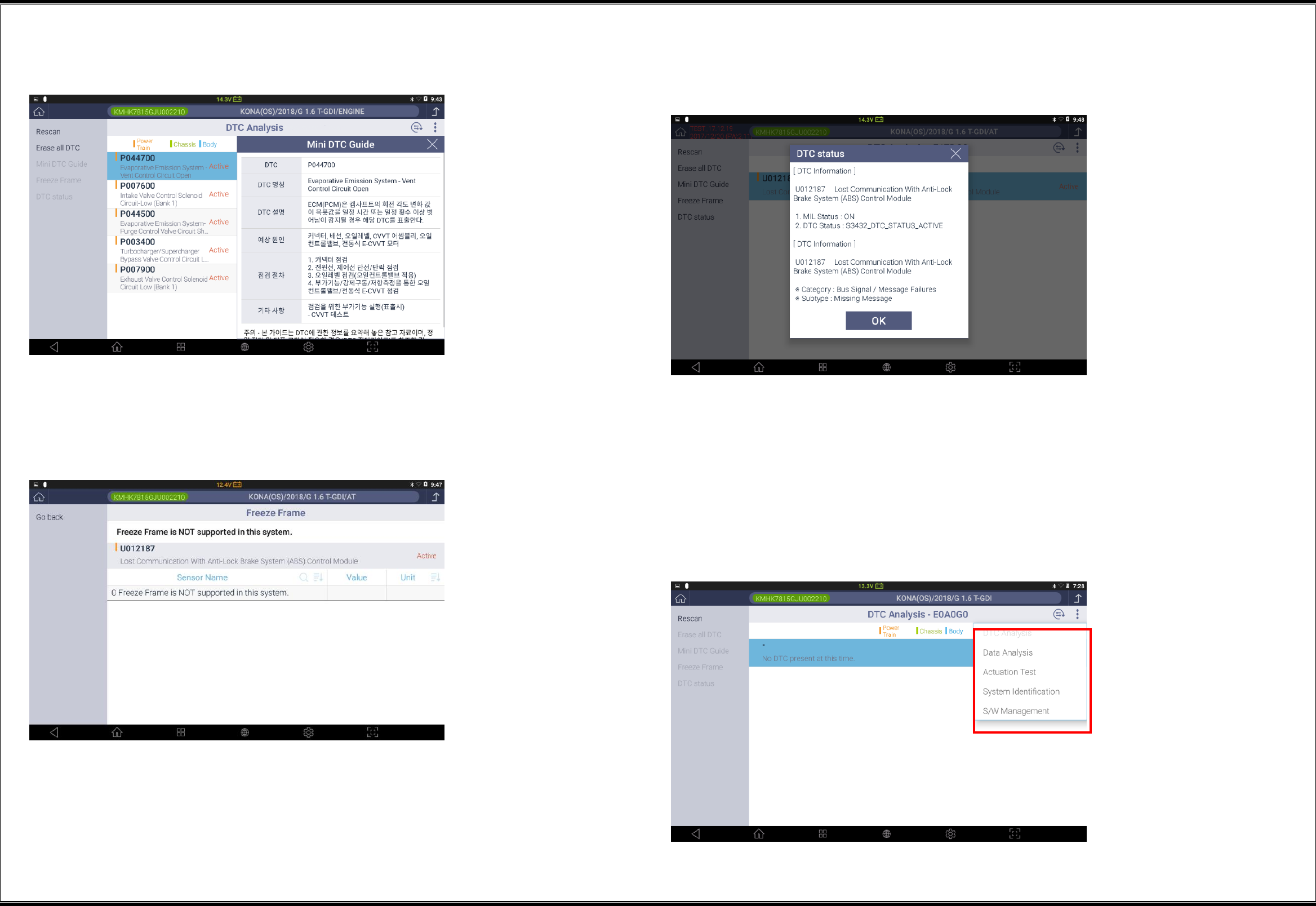
DTC Analysis .................................................................................... 13
▌Description of the DTC Analysis Functions ..................................................... 13
▌Switching of Diagnostic Functions ................................................................ 14
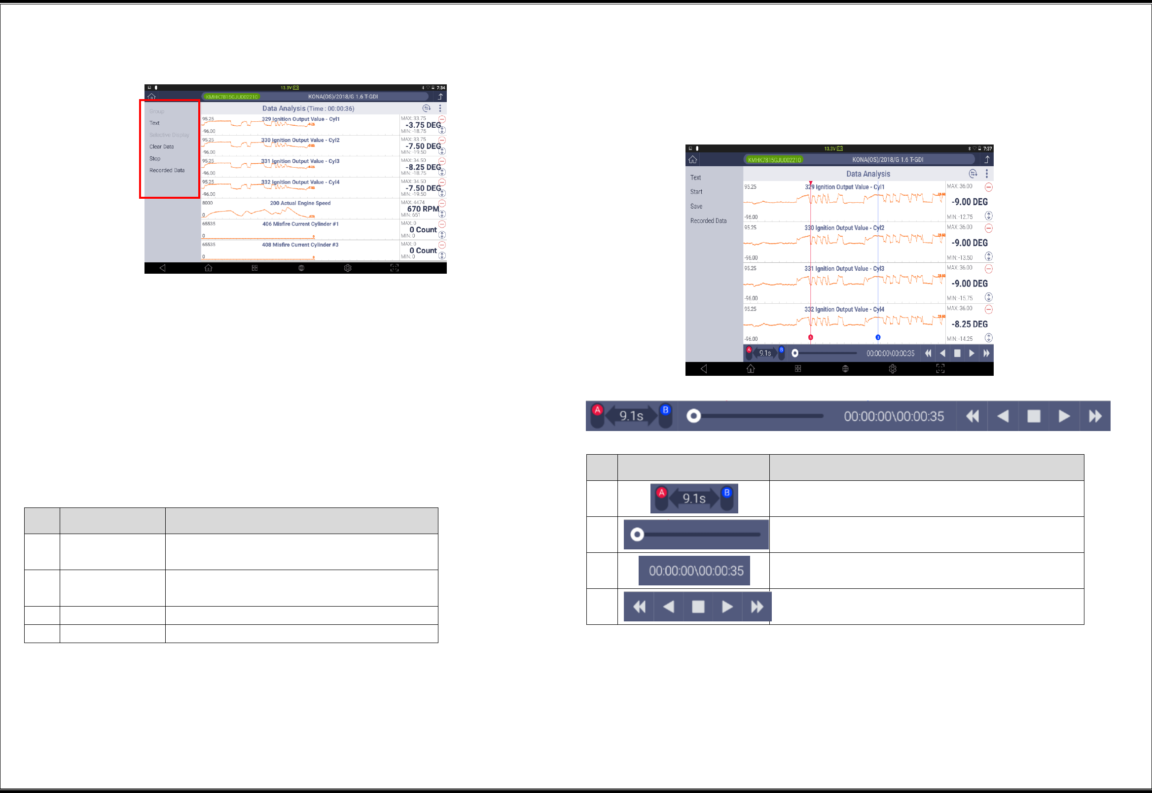
Sensor Data Analysis ......................................................................... 15
▌Description of the Sensor Data Analysis Window - Text Mode .......................... 15
Placement of sensor data ............................................................................... 16
▌Use of Groups ............................................................................................ 16
▌Use of Graph Mode ..................................................................................... 17
▌Selective Display ......................................................................................... 17
▌ Description of the Sensor Data Analysis Window - Graph Mode ...................... 18
▌Switching of Diagnostic Functions ................................................................ 21
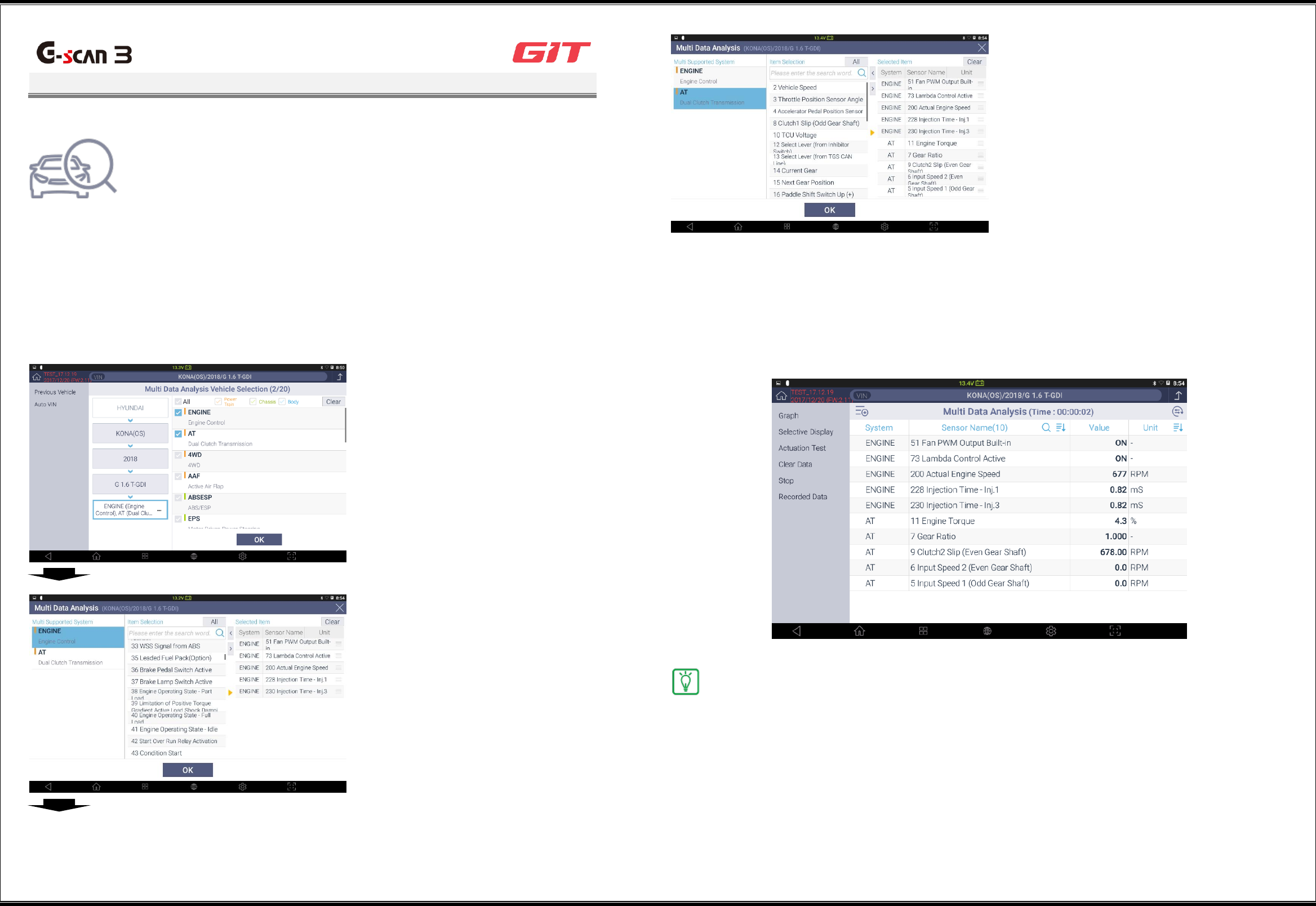
Multi Data Analysis ............................................................................ 22
▌Selection of Multiple Systems ....................................................................... 22
▌Multi Data Analysis ...................................................................................... 22
Actuation test ................................................................................... 23
▌Use of Actuation Test .................................................................................. 23
▌Switching of Diagnostic Functions ................................................................ 24
System Identification ......................................................................... 25
▌Use of System Identification ......................................................................... 25
▌Switching of Diagnostic Functions ................................................................ 26
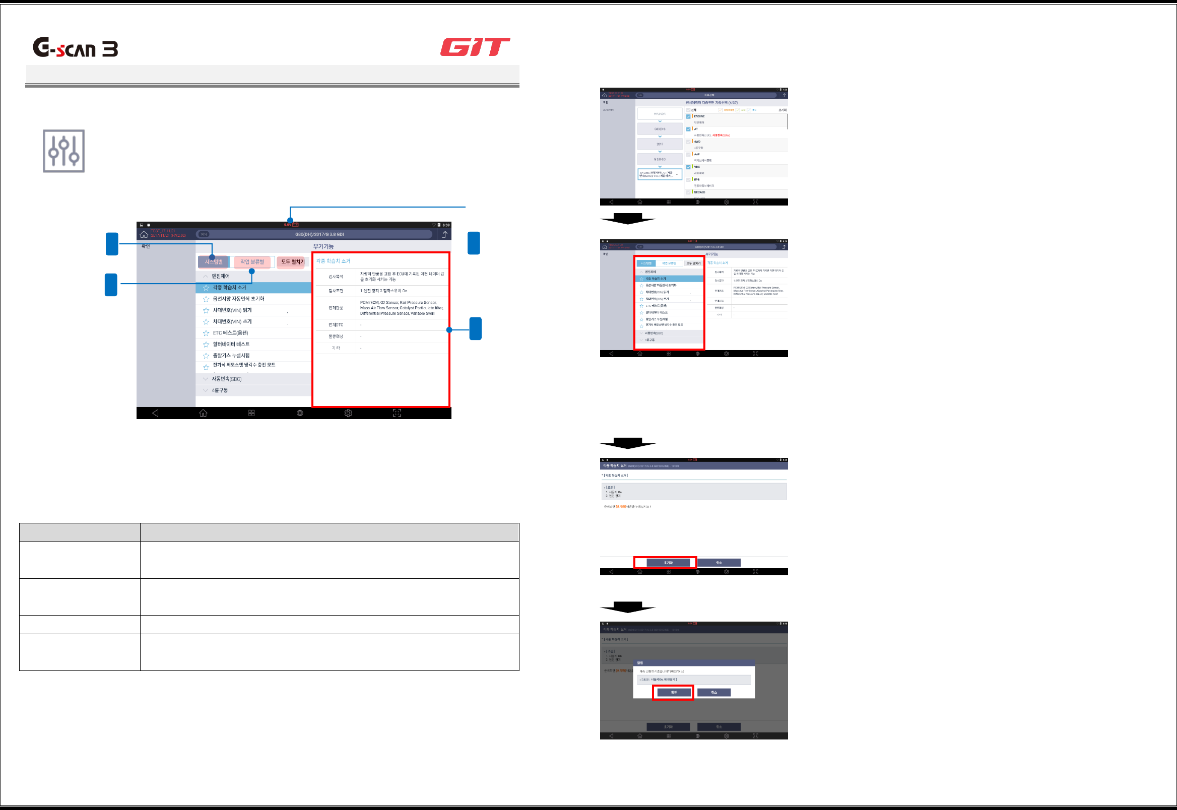
Additional Functions .......................................................................... 27
▌Use of Additional Functions.......................................................................... 27
▌Switching of Diagnostic Functions ................................................................ 28
Utility .............................................................................................. 29
▌Communication Line Inspection .................................................................... 29
▌Unit Converter ............................................................................................. 31
▌Calculator ................................................................................................... 31
Special Functions Calculator ........................................................................... 31
▌Abbreviation Dictionary ................................................................................ 32
▌OBD-II DTC Description Search .................................................................... 33
▌Voice Recorder ........................................................................................... 33
Camera ......................................................................................................... 33
▌Video ......................................................................................................... 33

1
Precautions before Product Use
G3180203
Any product faults caused by installation of an application not recommended by GIT or any
modification of the operating system made arbitrarily by a user may invalidate the product
warranty.
The applications and services included in this product are subject to change or be discontinued
without prior notice because of inevitable circumstances.
Precautions regarding environment of product use
Overheating may occur because of ambient environmental aspects if the following precautions
are not made. Make the following precautions when using this product, because failure to do so
may lead to reduced battery life, product damages, or fire accidents.
Do not keep this product at a place that is too high or with a too low temperature.
Do not expose this product to direct sunlight for an extended time.
Do not keep or use this product at a hot place, such as the inside of a car parked in
direct sunlight during summer.
Do not put this product near or inside an electric heater, heat-generating cooking device,
or high-pressure container.
Do not put this product in a microwave oven.
Do not keep or use this product at a place of high temperature and high humidity.
Do not keep this product inside a closed space for an extended time while its power is on.
Do not use a faulty charging adapter or battery.
Do not connect the charging adapter into a power outlet with a wet hand.
Precautions during product use
Use this product at a safe place so that it may not be damaged by impact or falling.
Use the dedicated pen when touching the screen. The use of a sharp tool, such as a
screwdriver or a gimlet, may damage the screen.
Safety when charging and using the battery
When connecting the AC/DC adapter, make sure to connect it firmly.
Make sure to use the AC/DC adapter that is provided with this product.
A swelling of the battery part of this product may lead to fire or explosion. Therefore, if
swelling is found, contact the seller or the manufacturer immediately.
When replacing the battery, make sure to use a battery provided by the product
manufacturer.
User safety
When using this product near a driving part of a vehicle, ensure that any cable or
instrument part of this product will not be in contact with the driving part.x`
Actions to be taken against overheating during product use
A function or an application that consumes a large amount of battery power may lead to
overheating. Although it is not because of a product defect, turn off the power of this product for
a short time to ensure user safety.
Actions to be taken against continuous overheating
Disconnect the charger, and completely turn off the power of the G-scan3.
Remove all the cables connected to this product.
2
Product Composition
G3180203
The product composition varies depending on the specifications of the package you purchase.
For purchase of additional components, contact the seller.
Basic Composition
Item Code
Item Name
Specification
G1CDDPA008
Adapter
Self Test
G1NDDMN002
G-scan3 Main Module
G-scan3 for AM (Black)
G1NZDCA001
Cable
DLC_G-scan3 (AM for general)
G1CDDPA013
Adapter
For AC/DC (KPL-040F)_GDS
G1PDDCA002
Cable
For CIGAR_G-scan
G1NDDHA002
Hard-carrying Case
For G-scan3
-
G-scan3 Quick Manual
G-scan3 AM (English Common)
G2SDDCA003
Cable
For Battery_HG
Components of Packages
Item Code
Item Name
ame
Specification
G0PDDCN001
Cable
Power (P-06061D)_For Australia
G1CDECA001
Cable
Power (2961)_For Europe
G1CDNCA001
Cable
Power(P04117A)_For North America
G0PDDCN001
Cable
Power (P-06061D)_For Australia
G1FDDPA001
Adapter
For 16-20A_G-scan2
G1FDDPA002
Adapter
For 16-20B_G-scan2
G1PZDPA001
Adapter
Toyota 17P S+1
G1PZDPA002
Adapter
Mitsubishi/Hyundai 12P+16P
G1PZDPA005
Adapter
J1939-9P
G1PZDPA006
Adapter
Isuzu 20P-10P-3P
G1PZEPA001
Adapter
BMW 20P
G1PZEPA002
Adapter
Audi/VW 4P
G1PZFPA002
Adapter
Toyota 17P R
G1PZFPA003
Adapter
Honda/Accura 3P
G1PZFPA004
Adapter
Mazda 17P
G1PZFPA005
Adapter
Subaru 9P
G1PZFPA007
Adapter
Nissan 14P
G2WDDCN006
Adapter
Ssangyong 14P
G1CDDPA007
Adapter
10-3-3
G1PZDPA007
Adapter
Hino 12P-5P
3
Basic Method for Product Use
G3180203
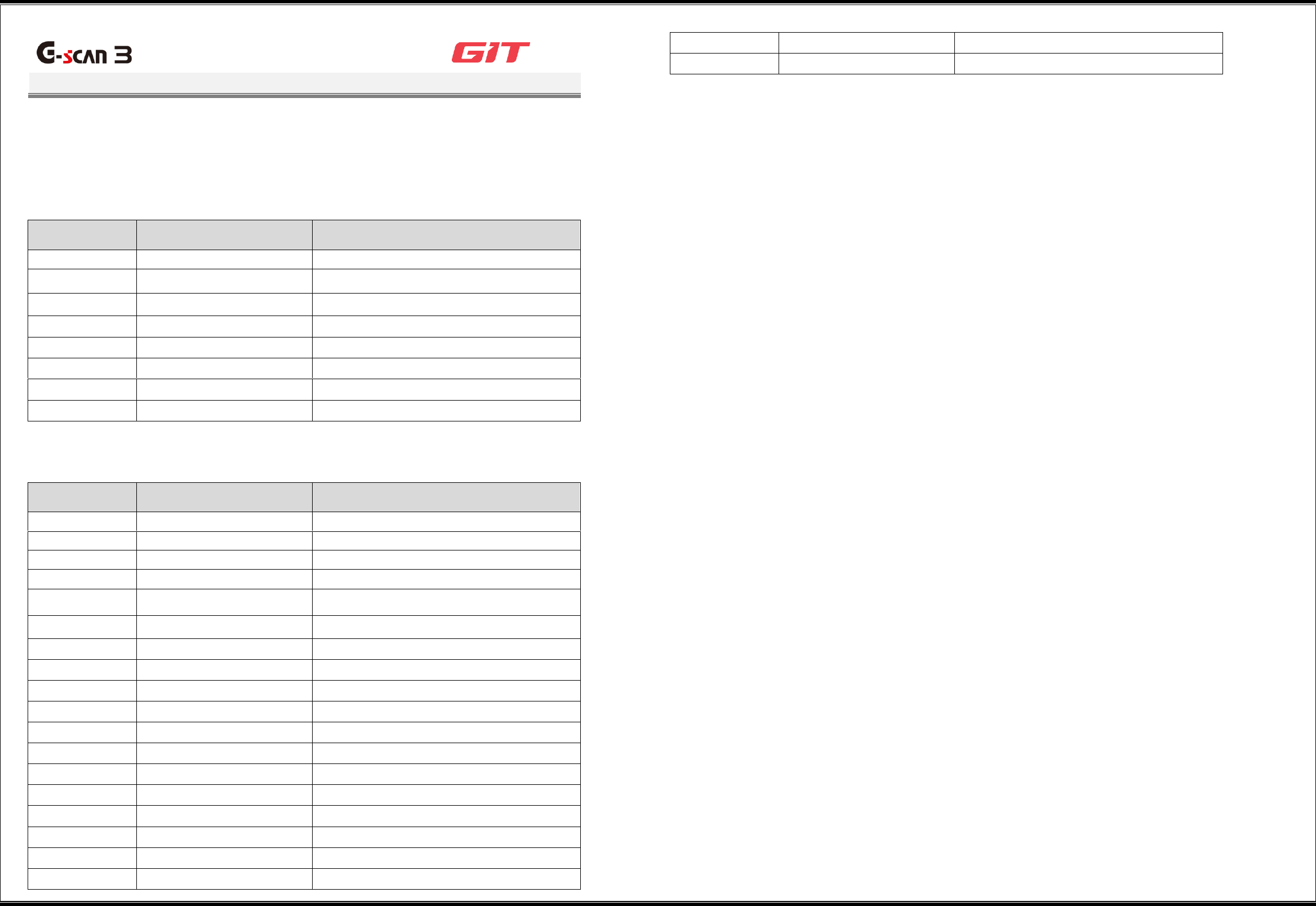
This section describes the part names and functions of G-scan3.
▌Part Functions of the Terminal
No.
Description
Quantity
1
Power button
Power on/off, and
restarting of G-scan3
terminal
2
Volume control button
F1: Speaker volume up
F2: Speaker volume
down
3
DLC connection terminal
Terminal for connection
of the DLC cable for
communications with a
vehicle
4
External device connection
terminal 1
①
LAN cable port for
Internet connection
②
HDMI cable connection
port
Monitor/TV set
connection
1
5
External device connection
terminal 2
①
USB device connection
②
Micro-SD card
1
③
USB device connection
port
④
Headphone connection
jack
6
Power connection terminal
Power connection with
a car battery or an
AC/DC adapter
1
7
Rear camera
8
Speaker
9
Dedicated fan
Some memory cards may not be fully compatible with this product,
and use of an incompatible memory card may lead to damages of
this product, SD cards, or SD card data.
①
②
③
②
①
1
2
4
3
5
6
9
7
8
⑥
④
4
▌Use of Outer Buttons
Power button
You can turn on/off the power of G-scan3 by using the power button placed at
the top of the main module.
Power on
When G-scan3 is turned off, a long press of the power button will turn on its power.
Power off/restarting
When G-scan3 is turned on, and the window is on, a long press of the power
button will display the popup window for selecting “Shutoff” or “Restart.”
Clicking of the "Shutoff" or the "Restart" button will change to the selected
status of the power.
Power-saving mode
While G-scan3 is turned on and the window is off, a short press of the power
button will change the power mode to power-saving mode, and will shut off
the window. To resume the use of G-scan3, a short press of the power button
is needed to release the product from the power-saving mode.
Volume control buttons
You can change the volume level with the volume control buttons.
The volume level is displayed on the window as follows:
Shutoff
Restart
5
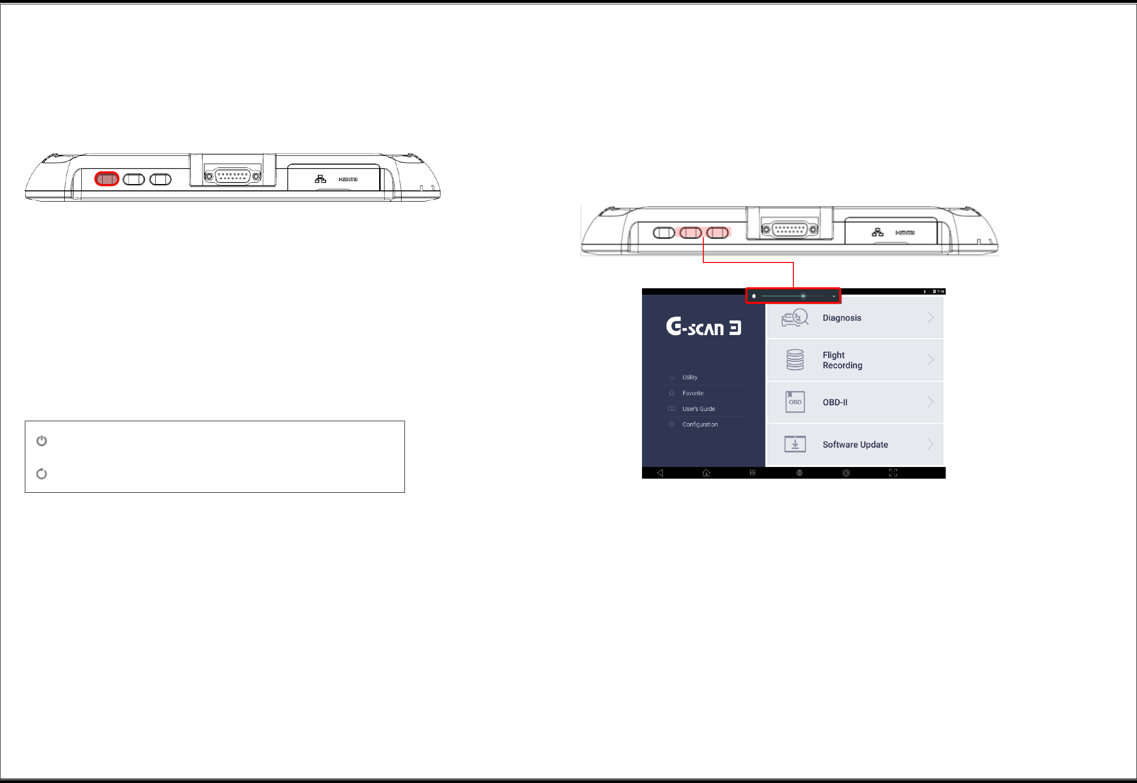
▌ Functional Buttons of G-scan3
The functional buttons placed at the bottom of the first window of G-scan3 provide
various convenience functions for the user.
No.
Icon
Button Name
Description
1
Cancel
This returns the current window to the
previous window.
2
Home
This returns the current window to the
desktop window.
3
App Running
This displays the applications that are
running.
4
Web Browser
This runs the Internet browser.
5
Setting
This enables setting of the body and
configuration of G-scan3.
6
Screen Capture
This enables screen capture and image
editing.
“Home” button
This returns the current window to the desktop window of the Android OS of G-scan3.
"App Running" button
This displays the applications that are running on G-scan3.
6
"Web Browser" button
This runs the Internet browser to connect G-scan3 to the Internet with wired/wireless network.
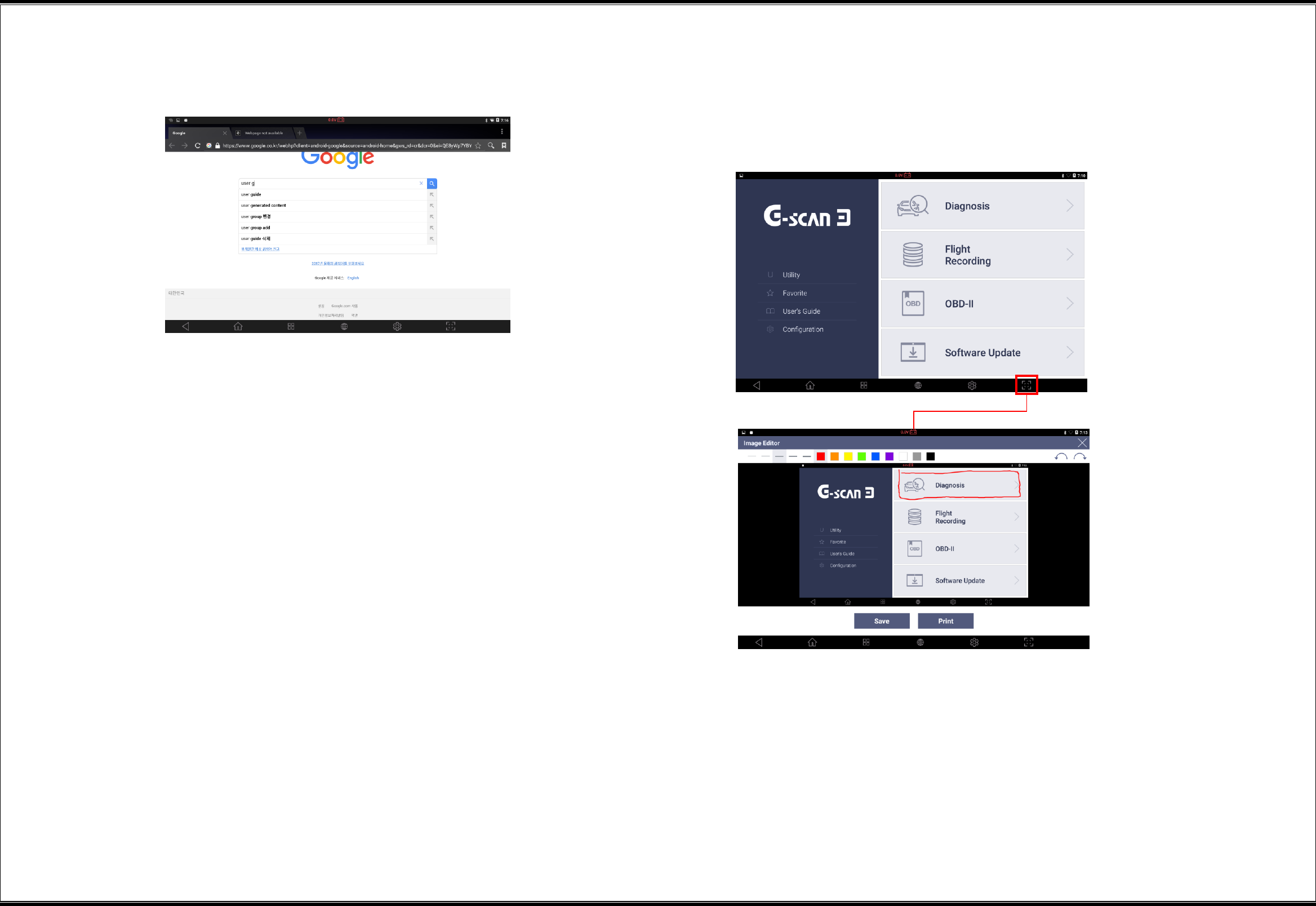
"Screen Capture" button
This enables an instant screen capture during G-scan3 use, and a simple memo or drawing on
captured images with a dedicated pen.
Captured images can be saved in files, or printed out.
7
Start of Vehicle Diagnostic Functions
G3180203
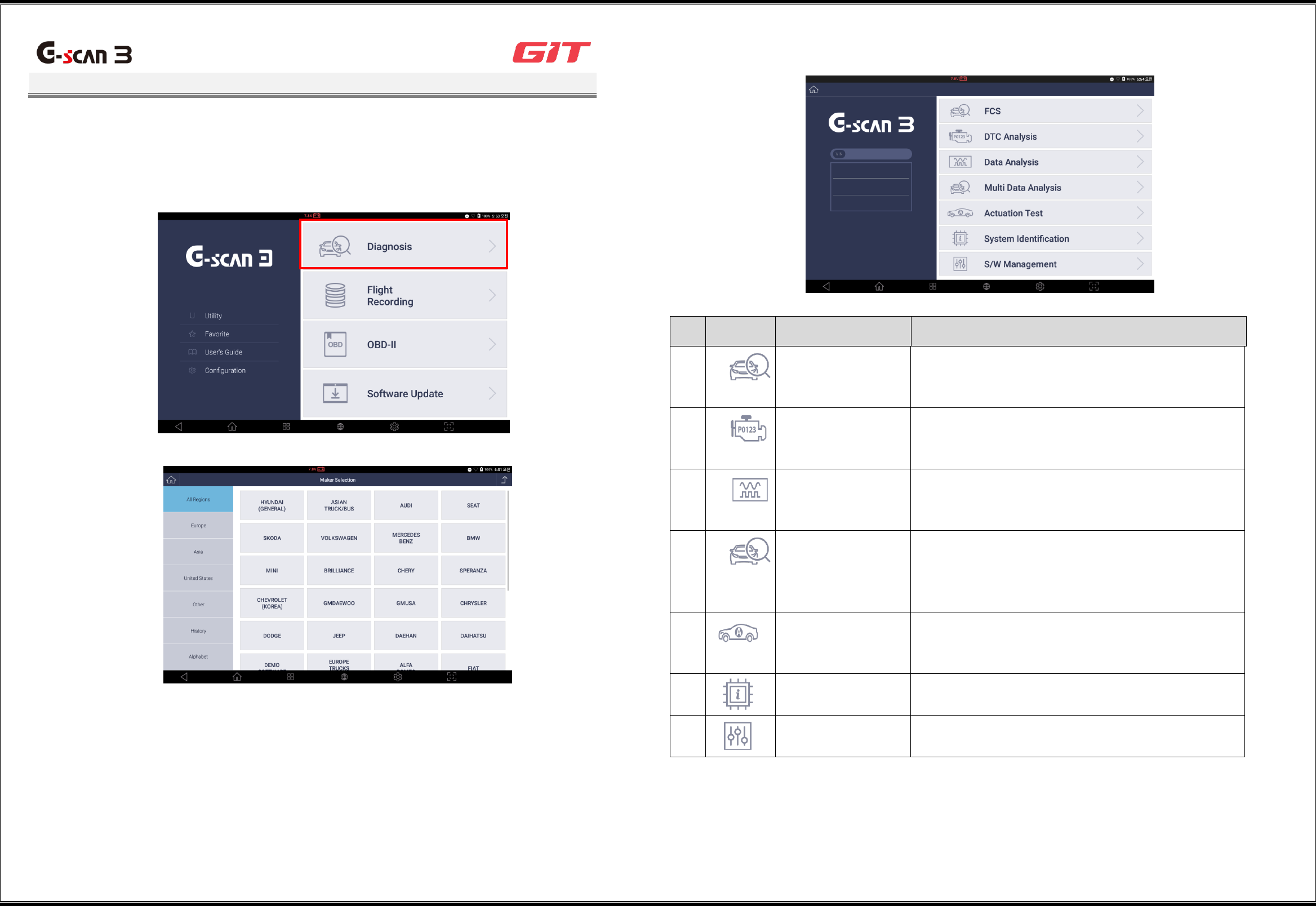
When using the vehicle diagnostic functions of G-scan3, select [Diagnosis] on the initial
window. Then a window will be displayed for selecting an automaker. Select the maker
that matches the vehicle to be diagnosed.
The structure of the diagnostic functions available on the main window of G-scan3 is as follows.
Read the descriptions of the functions before using them.
No.
Icon
Function Name
Description
1
FCS
This enables scanning of the diagnostic trouble
codes (DTCs) that are saved for all the systems of
a vehicle that support diagnostic communications.
2
DTC Analysis
This enables scanning of the DTCs that are saved
for a single selected system, and displays the
trouble information of a vehicle.
3
Data Analysis
This enables communication with a single
selected system, and displays the status value of
sensor items.
4
Multi Data Analysis
This applies only to CAN communications
systems. It establishes communications with
multiple systems, and displays the status value of
sensor items.
5
Actuation Test
This enables checking of normal operation by
forcibly driving or stopping the actuators mounted
on a vehicle.
6
System
Identification
This displays the identification of the systems
mounted on a vehicle.
7
S/W Management
This enables additional setting, inspection,
initialization, etc., after maintenance of a vehicle.
8
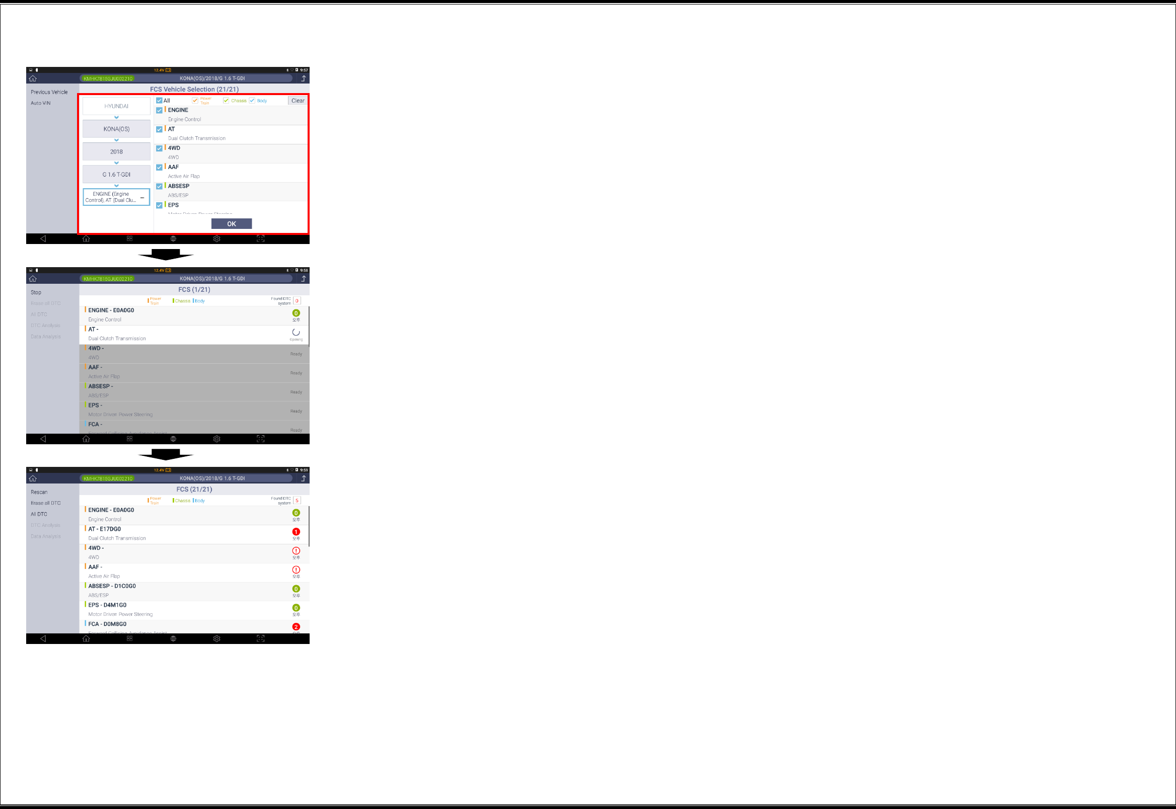
Vehicle Model Selection
G3180203
This is the stage where a vehicle model to be diagnosed is selected. A vehicle model can be
selected by the "Auto VIN" or the manual selection method.
Auto VIN: This method reads the vehicle identification number (VIN) from the ECU of the
vehicle, and selects the VIN automatically.
Manual selection: In this method, vehicle identification should be selected manually in the
following sequence: manufacturer, vehicle model, manufacture year, engine type, and
system.
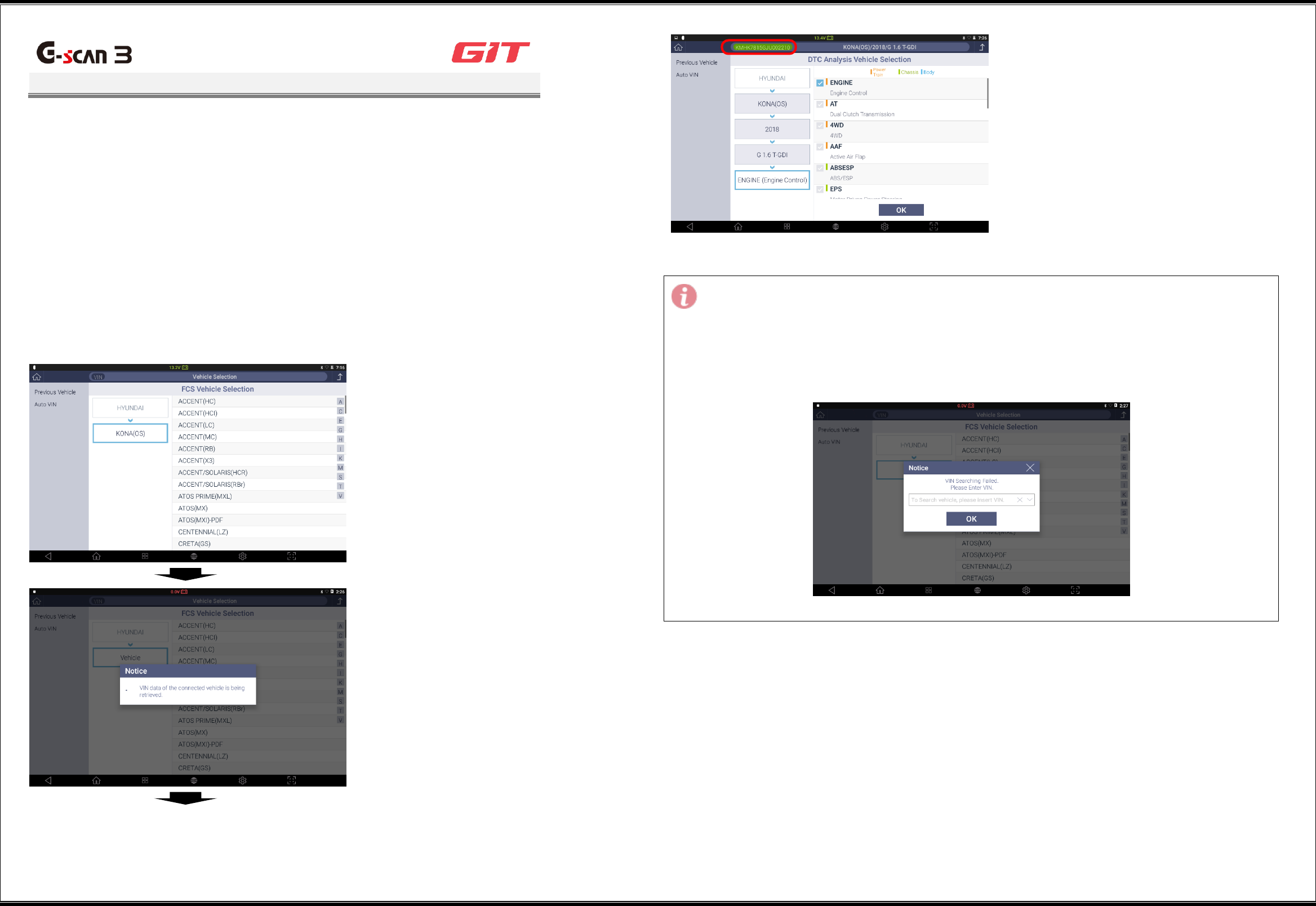
Auto VIN
This method reads the vehicle identification number (VIN) from the ECU of the vehicle, and
selects the VIN automatically.
1
Click [Auto VIN] in the left button tab.
2
Communication with the vehicle will
be established, and the VIN will be
read.
3
The model, manufacture year, and
engine specifications will be selected
automatically, and the VIN will be
displayed at the top of the diagnostic
program.
Note:
When no VIN can be read in the "Auto VIN" mode, the following VIN input popup window will
be displayed:
Enter the 17-digit (numbers + alphabets) code of the vehicle and click the [OK] button, and
the vehicle selection will be completed automatically.
9
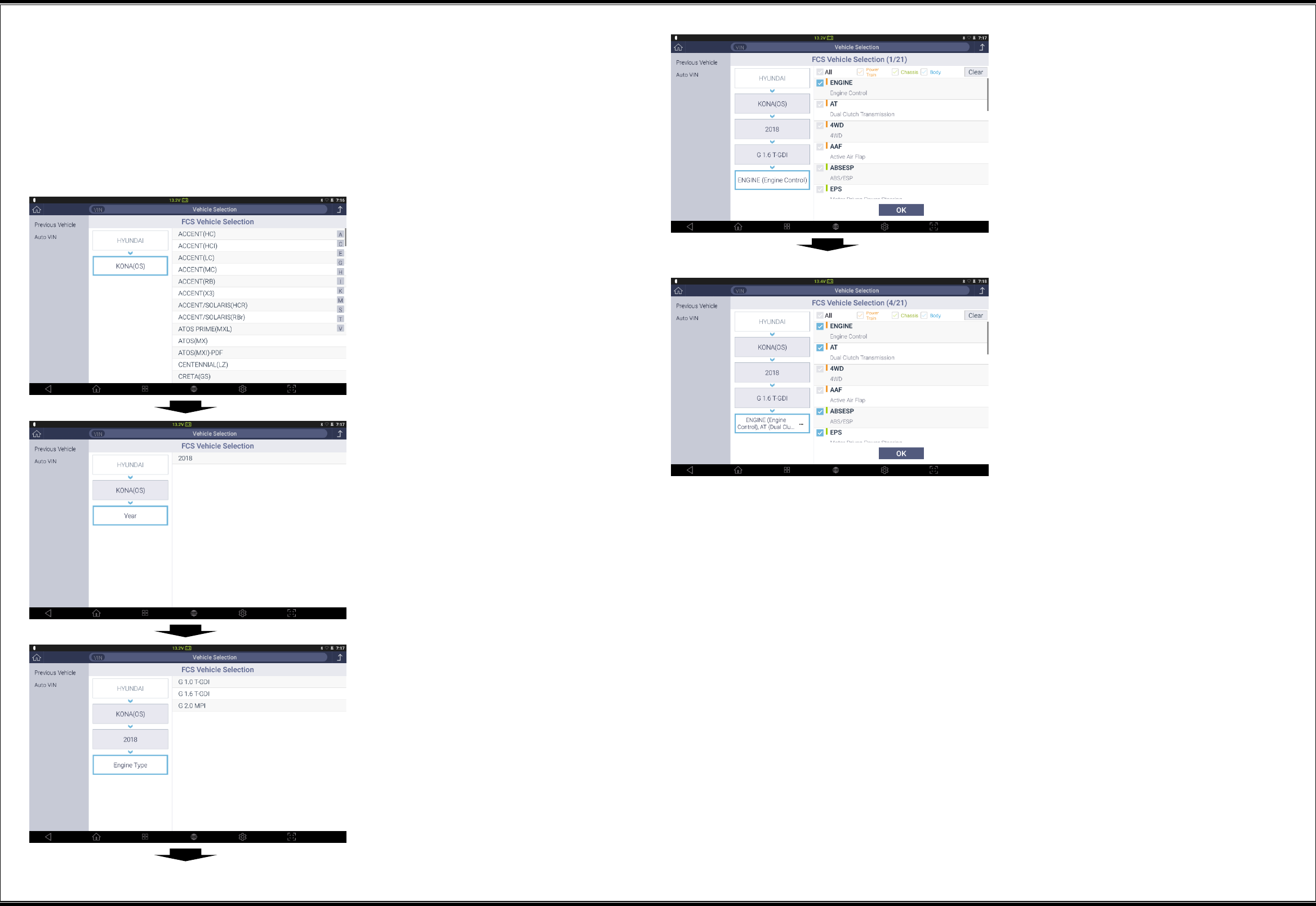
Manual selection
In this method, identification of the vehicle to be diagnosed should be selected manually for the
diagnostic communications.
Vehicle identification should be selected manually in the following sequence: manufacturer,
vehicle model, manufacture year, engine type, and system. In the case of some diagnostic
functions for multiple systems, you can add systems to be diagnosed.
1
Select the model of the vehicle to be
diagnosed.
2
Select the manufacture year of the
vehicle to be diagnosed.
3
Select the engine type of the vehicle
to be diagnosed.
4
Select the system to be diagnosed.
5
For the following diagnostic functions
selected on the main window, you
can select multiple systems:
- FCS
- Multidata Analysis
- System Identification
- S/W Management
10
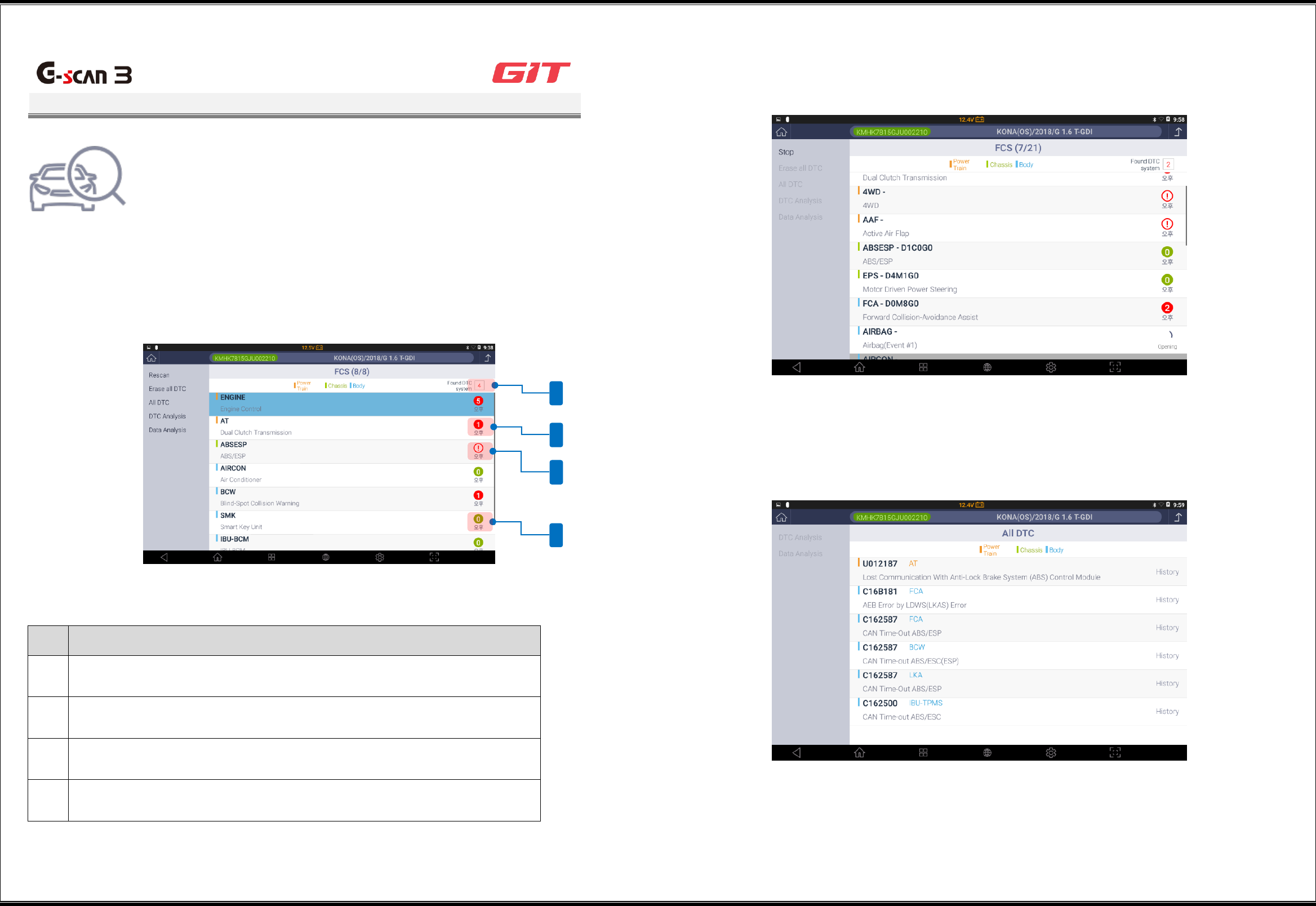
All DTC Scanning
G3180203
This function displays the overall diagnostic results of the
vehicle by making diagnostic communications with multiple
control systems mounted on a vehicle, and shows the DTCs
saved in the systems.
▌Window Structure and Description of All DTC Scanning
The result of the “All DTC” scanning will display the number and the status of the scanned DTCs
on the right of the window after making diagnostic communications with the systems.
Result display of DTC scanning
No.
Description of Result Display
1
This indicates the number of systems in which DTCs have been found.
2
If any DTCs are found, they will be indicated in red, and the number of
DTCs found in the system will be displayed.
3
This will be indicated when the system does not respond.
4
If no DTC is found, it will be indicated in green.
▌All DTC Scanning Functions
Rescan
This rescans DTCs of all the selected systems, and updates the information on DTC occurrence.
Erase all DTC
This erases all DTCs found in the “All DTC” scanning.
All DTC
This displays all DTCs found in the “All DTC” scanning.
4
1
2
3
11
DTC Analysis
On the "All DTC” scanning window, after a system is selected, clicking of the [DTC
Analysis] button will change the window to the one for the DTC analysis functions.
* For the method that uses the DTC analysis functions, see [DTC Analysis].
Sensor data Analysis
On the "All DTC" scanning window, after a system is selected, clicking the [Sensor data Analysis]
button will change the window to the one for the sensor data analysis functions.
* For the method that uses the sensor data analysis functions, see [Sensor data Analysis].
12
▌All DTC Scanning
1
Select the manufacturer, vehicle
model, manufacture year, engine
type, and system. Then click the [OK]
button to start "All DTC" scanning.
* FCS is one of the functions for
which multiple systems can be
selected.
2
It will scan the control systems
sequentially.
3
It will display the DTC occurrence
status of the control systems.
13
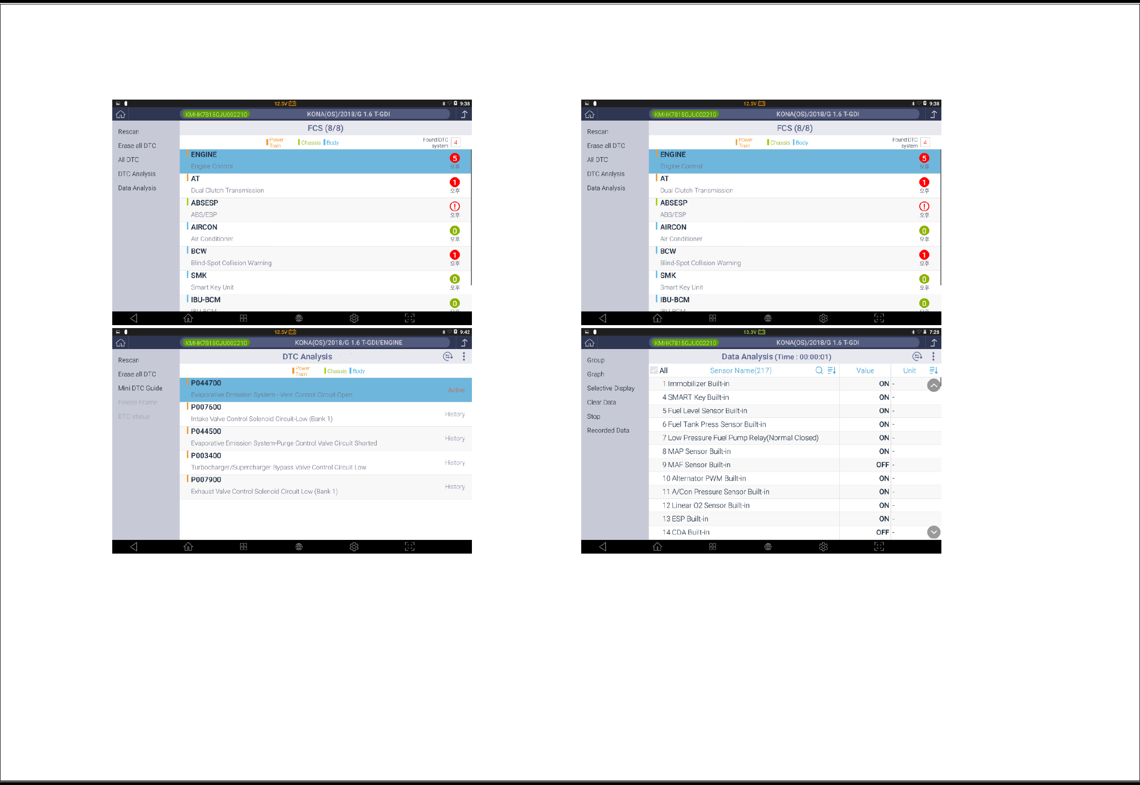
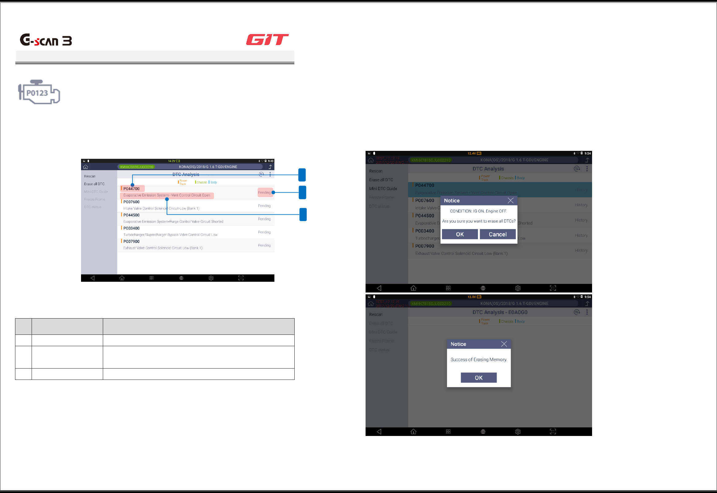
DTC Analysis
G3180203
It will scan the DTCs saved in the control systems of the
vehicle, and display the detailed information on the DTCs.
▌Checking on System DTC Information
No
.
Function Icon
Description
1
DTC
This displays the DTC of the control system.
2
DTC status
This displays the status of the DTC of the control
system (ACTIVE, HISTORY, or PENDING).
3
DTC description
This describes the DTC of the control system.
▌Description of the DTC Analysis Functions
Rescan
This rescans the DTCs of the selected system. This button has the same function as the "Insert
Button Icon" at the top of the window.
Erase all DTC
This erases all the DTCs saved in the control system. The status of the vehicle should be such
that the start key is in the “ON” position and the engine is off.
1
3
2
14
Mini DTC Guide
This provides a simple guide to the DTCs scanned in the DTC Analysis.
Trouble status data
This enables a query to the status value of the related sensor data items saved during DTC
occurrence.
* Clicking of the [Go back] button will change the window back to the DTC Analysis window.
DTC status
This shows a short description of the DTC, and its current status.
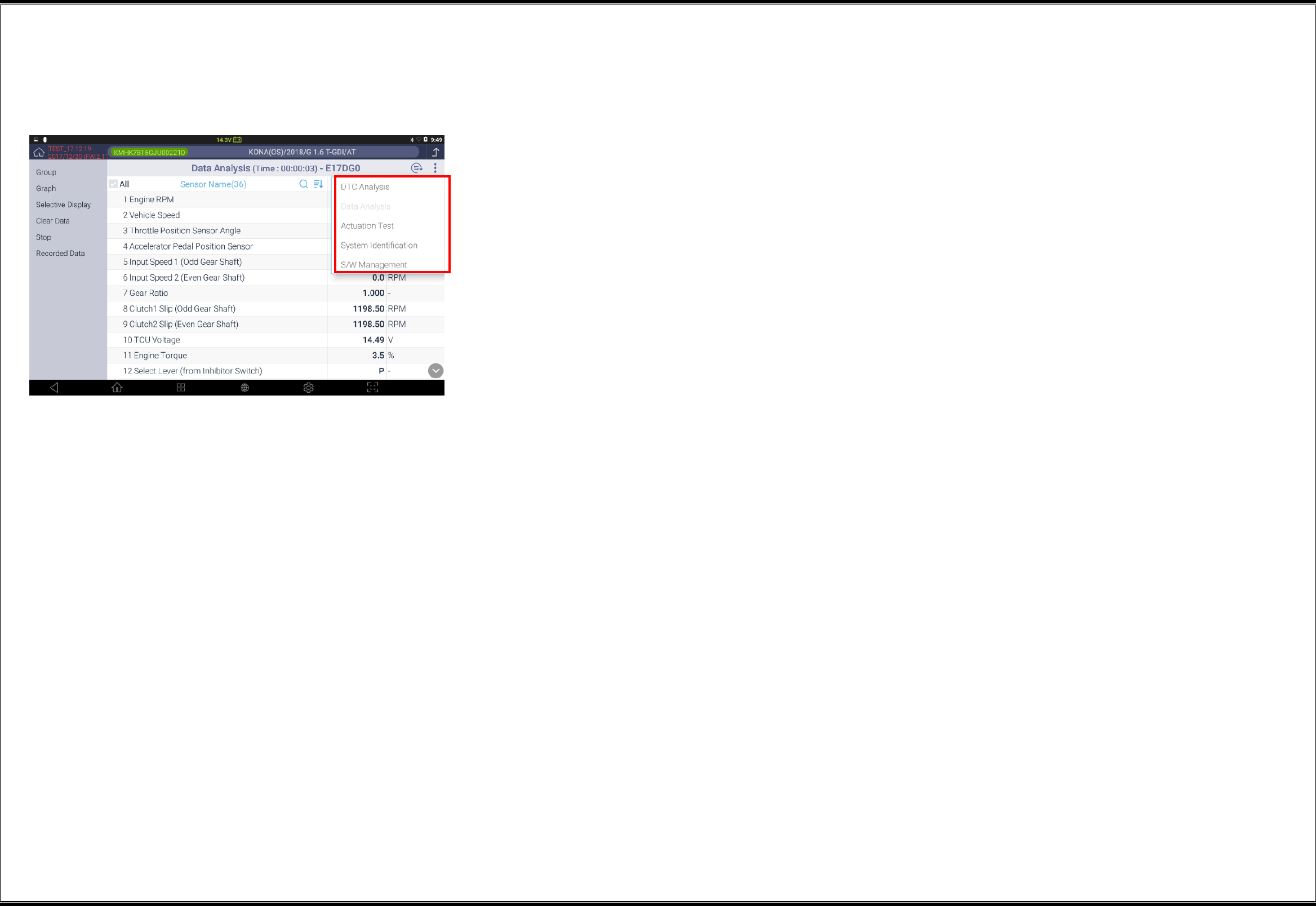
▌Switching of Diagnostic Functions
While diagnostic communications between G-scan3 and the vehicles are established, you may
switch to different diagnostic functions:
Data Analysis
Actuation Test
System Identification
S/W Management
15
Sensor Data Analysis
G3180203
This function displays the operating status of the sensors and the
actuators of the control systems mounted on the current vehicle
through communications with the control systems.
▌Description of the Sensor Data Analysis Window - Text Mode
No.
Description
1
Sensor data group name
2
Sensor data value
3
Sensor data unit
4
Scan
5
Sort
Description of function buttons
No.
Function Icon
Description
1
Group
This displays the sensor data items that
belong to the selected type of the group list
on the window.
2
Graph
This displays the selected items of the group
in graph.
3
Selective Display
This displays only the sensor data items
selected at the top.
The smaller the number of the selected items,
the more precise the displayed data.
4
Clear Data
This clears the sensor data being recorded.
5
Recorded Data
This displays the data viewer for analyzing the
data recorded in the past.
Scan sensor data
This scans sensor data items, and displays them at the top.
Sort sensor data
This carries out user-defined sorting of sensor data. The sorting criteria available are item
name and unit.
4
1
5
3
2
16
Placement of sensor data
You can place the necessary items selected among the ECM data under communication
at the top. Fixation of sensor data items is a prerequisite when converting to the graphic
mode.
Method for fixating/clearing items
Clicking of the sensor data items on the window will place them at the top, which are indicated in
blue. Similarly, clicking of the sensor data items placed at the top will clear its placement from
the said position.
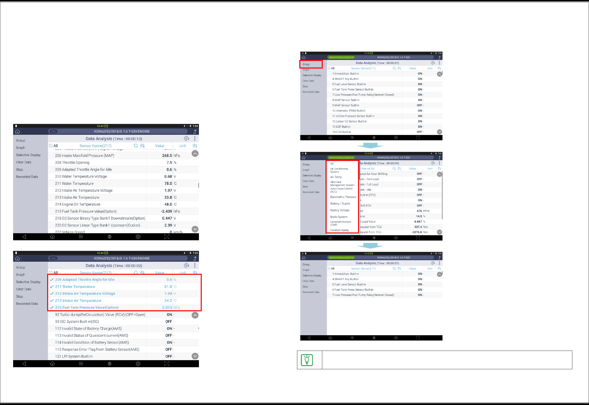
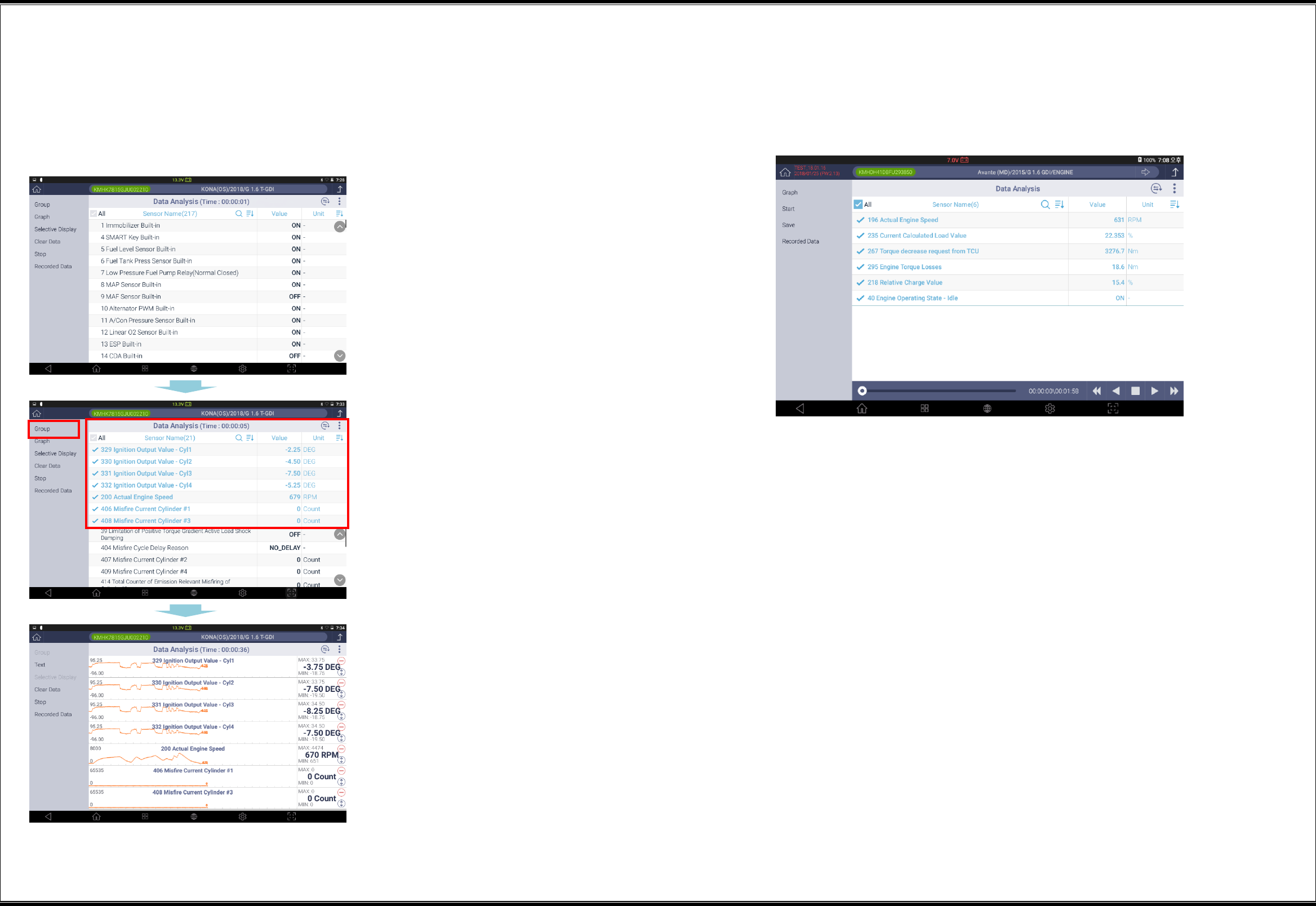
▌Use of Groups
Sensor data items are categorized according to group attributes, and it is possible to analyze
data by categorizing sensor data into groups.
1
Click the [Group] button in the left
list.
2
Click a group to be diagnosed among
the list of the groups supported by
the control systems.
3
Only the sensor data items defined
for the selected group will be
displayed on the window.
To view all the groups in the list of the groups of sensor data items, click [All] for the
group list.
17
▌Use of Graph Mode
The graph mode displays the values of sensor data items in a graph so that the user may visually
identify the changes in sensor data values.
Viewing in graph mode
1
Select and place the sensor data
items at the top.
2
After the sensor data items are
selected, click the [Graph] button.
3
Then the sensor data items placed at
the top will be displayed in a graph.
▌Selective Display
This function displays only the sensor data items selected by the user to increase the accuracy
of the sensor data display.
18
▌ Description of the Sensor Data Analysis Window - Graph Mode
Text
This switches the window display from the graph mode to the text mode.
Clear Data
This clears the data collected through communications with the control systems of the vehicle,
and restarts data collection.
Stop
This stops the process of collecting sensor data from the control systems of the vehicle.
Recorded Data
No.
Function Icon
Description
1
Text
This switches the graph mode to the text
mode.
2
Clear Data
This clears the collected sensor data values,
and restarts data recording.
3
Stop
This stops sensor data recording.
4
Recorded Data
This displays the recorded data.
Description of the graph analysis function
While sensor data are collected in the graph mode, clicking of the [Stop] button will
switch the window to the data analysis mode.
No.
Function Icon
Description
1
This enables activation of cursors A and B, and
displays the time gap between Cursor A and Cursor B.
2
This indicates the playback position of the sensor
data recording on a bar.
3
This indicates the playback position of the sensor
data recording in the time unit.
4
This plays/stops sensor data records in the
regular/reverse direction.
19
To the left of the sensor data;
No.
Icon
Description
1
This excludes the item from the list of graph
display.
2
Maximum
This indicates the maximum value on the current
graph display window.
3
Minimum
This indicates the minimum value on the current
graph display window.
4
This enlarges the graph of the pertaining item to
the maximum.
However, it will not exceed the graph display
area.
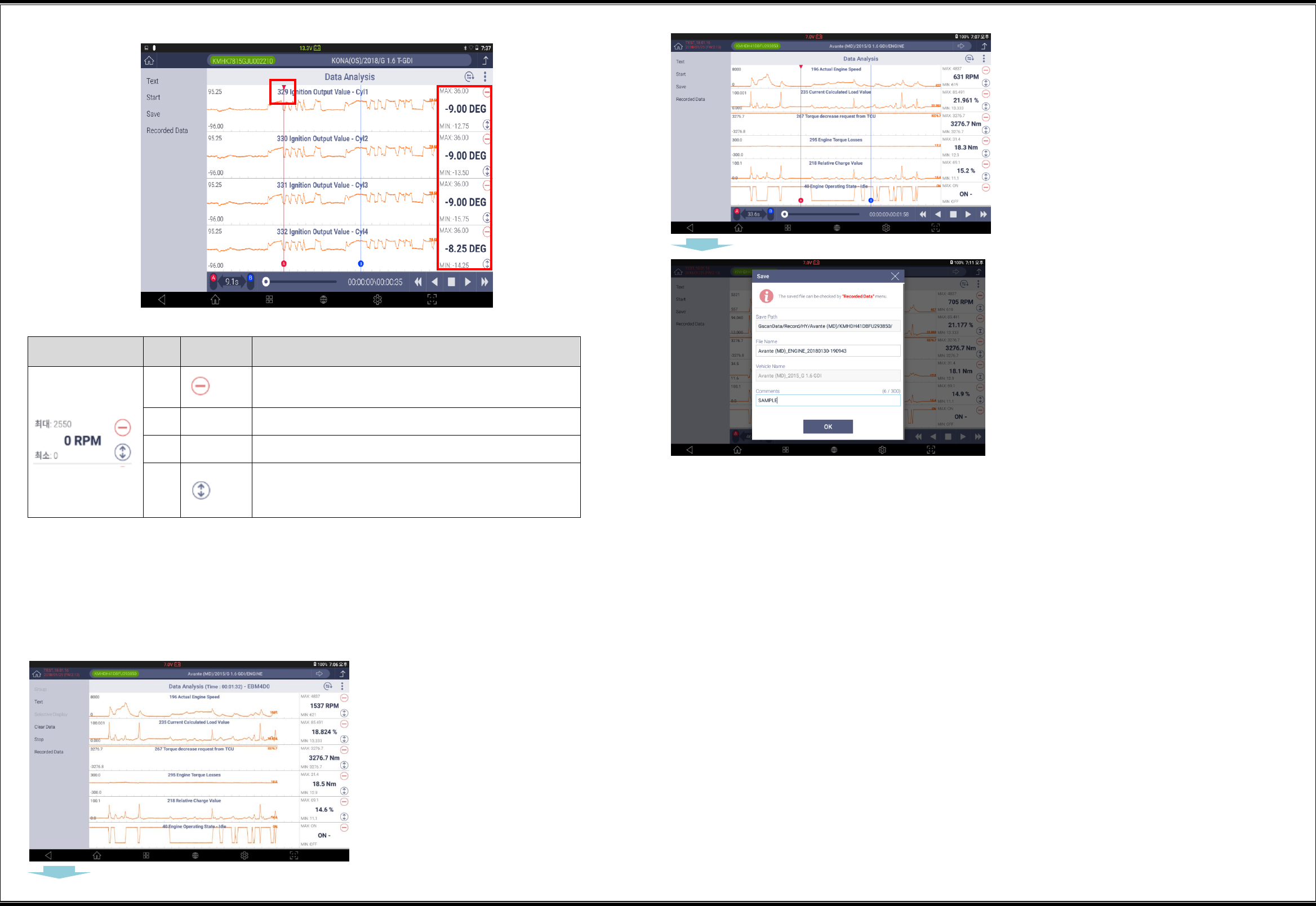
Save data
This saves the sensor data acquired in this the sensor data function in a file. The data can be
retrieved with the "Stored Data Analysis" function.
Save data
1
Click the [Stop] button to
stop data reception.
2
When data reception is
stopped, the "Data
Analysis" window will
appear as shown in the
left figure.
3
Clicking of the [Save]
button will prompt a
window for designating
the file saving path and
inputting remarks.
After inputting remarks,
click the [OK] button.
20
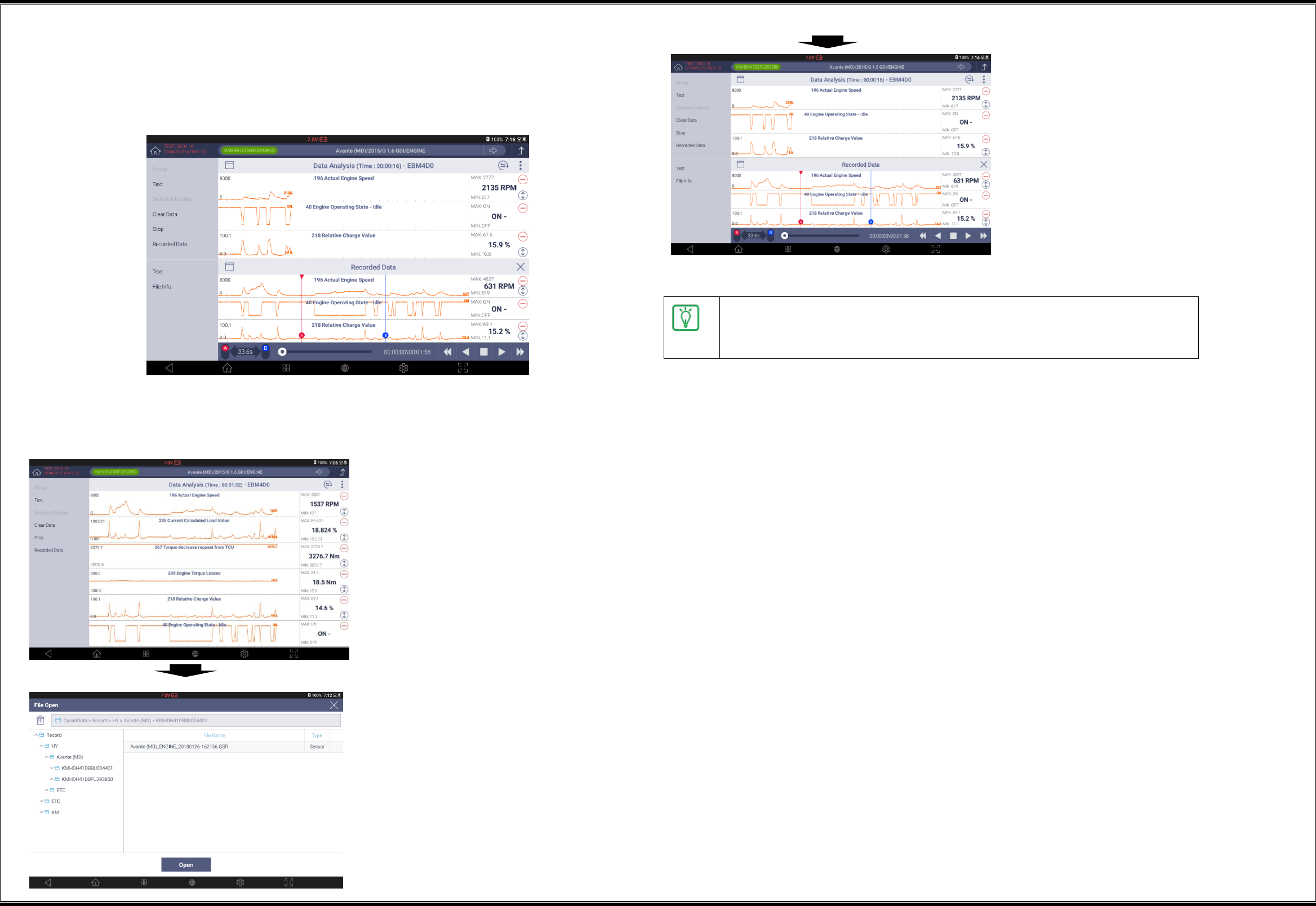
Retrieving of stored data
In the graph mode, you can call the existing sensor data records, and compare them.
At this time, the top part of the window will display sensor data values and the
bottom part will display the saved data playback bar.
1
Click the [Recorded Data]
button.
2
Go to the data saving
path, find a file, and click
the [Open] button.
3
Clicking of the [Save]
button will prompt a
window for designating
the file saving path and
inputting remarks.
After inputting remarks,
click the [OK] button.
The sensor data will be stored in a file with *.GSR format, which can be
rechecked at the [Data] function of the initial window, or [Recorded
Data] in the “Sensor Data Analysis” function.
21
▌Switching of Diagnostic Functions
From the DTC diagnostic function, it is possible to short-switch to the following diagnostic
functions:
Data Analysis
Actuation Test
System Identification
S/W Management
22
Multi Data Analysis
G3180203
This function enables concurrent communications with multiple
ECMs, and displays sensor data items designated for multiple
systems on the window. The [Multi Data Analysis] function
supports only the ECM systems under diagnosis that use the
CAN protocol.
▌Selection of Multiple Systems
In Step 2 of the multisystem selection, sensor data items will be listed for the "Multi
Supported System" in blue shade in the left column. Select a system, and then select
sensor data items.
1
Select a control system to be
subjected to diagnostic
communications, and click the
[OK] button.
2
When sensor data items of the
control system are selected, they
will be registered in the left list.
3
After selecting sensor data items
of the control system to be
registered as selected items, click
the [OK] button to complete the
sensor data item selection.
▌Multi Data Analysis
In the "Multi Data Analysis" function, the listing of sensor items and sensor values is the same as
that of the "Sensor Data Analysis" function. The system information of the sensor data items is
listed on the left.
The structure of the window and the method for using this function
are the same as those of the "Sensor Data Analysis" function.
23
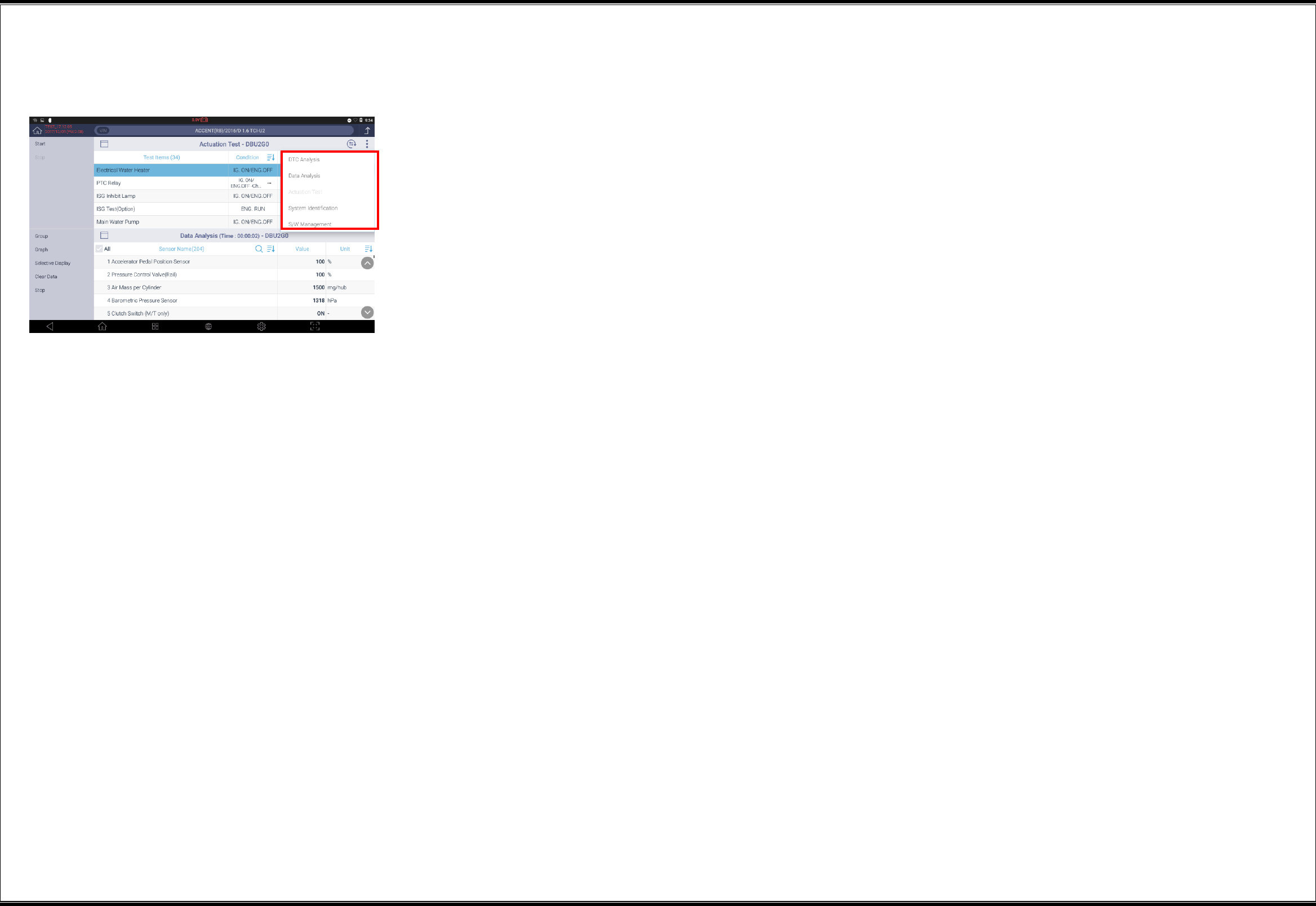
Actuation test
G3180203
This function drives the actuators of the systems of a vehicle
by controlling the ECU of the vehicle with G-scan3, and
enables checking the faults on the actuators.
* The supported actuation test items may vary depending on
the control systems of vehicles.
The actuation test window comprises "Actuation Test" at the top and "Data Analysis" at the
bottom.
Its purpose is to identify changes in the related sensor items by forcibly operating actuators.
A
B
Item
Description
A
Actuation test
Along with the actuation test items supported by
the control systems of the vehicle, actuation
“condition," "duration," and "result" are displayed.
B
Sensor data
analysis
The sensor data items supported by the control
systems of the vehicle and their status values are
displayed.
▌Use of Actuation Test
1
Select a control system to be
subjected to diagnostic
communications, and click the
[OK] button.
2
Select the sensor data items
related with the actuation test.
To facilitate the reading, you may
set the window in graphic mode.
3
After selecting an actuation test
item, click the [Start] button at
the upper-left part.
* Depending on the actuation test
items, you may stop the actuation
by clicking the [Stop] button.
24
▌Switching of Diagnostic Functions
From the actuation test function, it is possible to short-switch to the following diagnostic
functions:
Data Analysis
DTC Analysis
System Identification
S/W Management
25
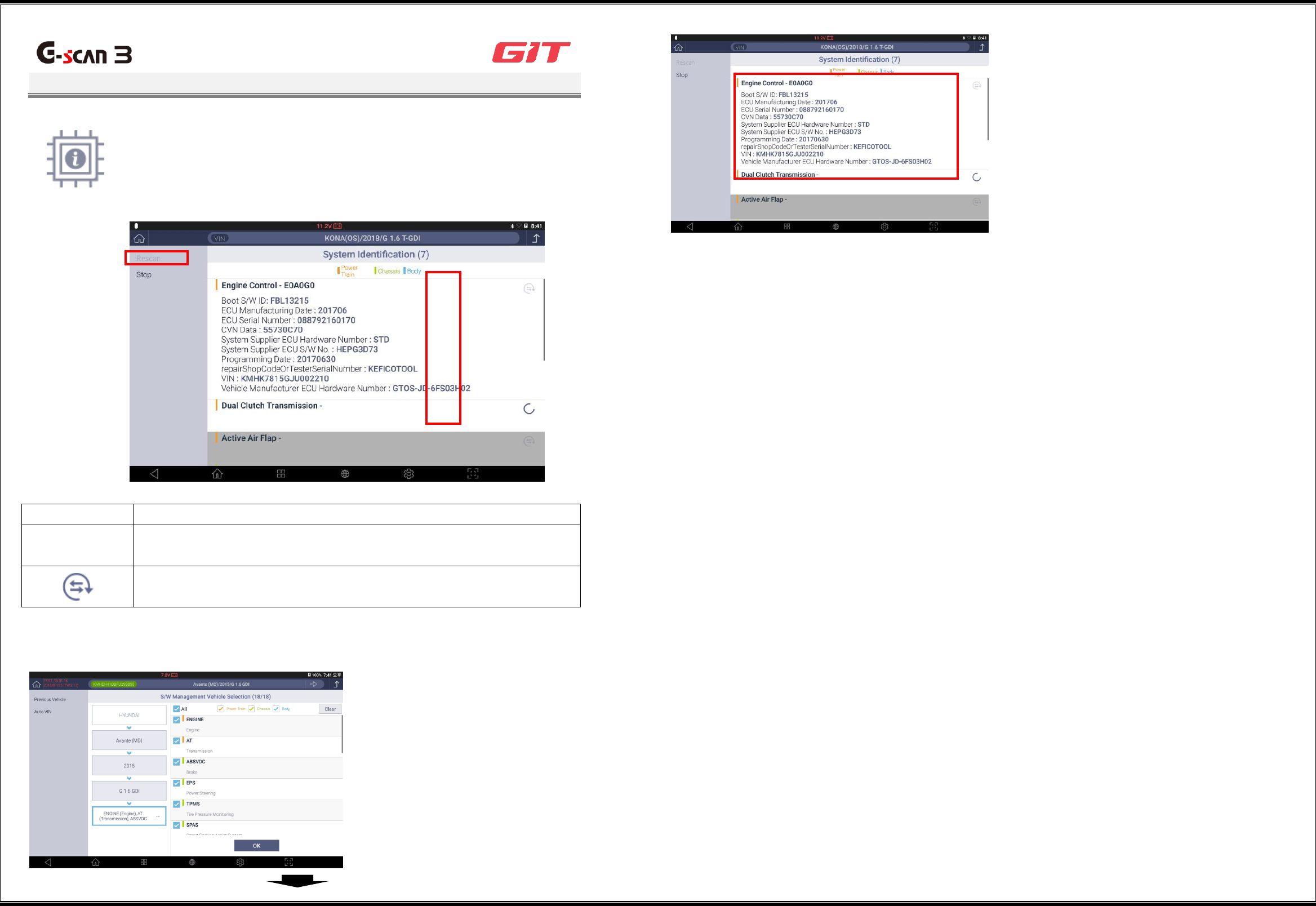
System Identification
G3180203
This function reads and displays the identification of the control
systems mounted on a vehicle.
The system identification function on the initial window enables
selection and identification of multiple systems.
Item
Description
Rescan
This rescans identification of all the control systems selected during
the vehicle selection.
The rescanning will be done only for the control systems on which
the "rescan" button is indicated.
▌Use of System Identification
1
Select all the control
systems to be scanned in
terms of system
identification, and click
the [OK] button.
2
The identification
information on the
control systems selected
during the vehicle
selection will be
displayed on the window.

26
▌Switching of Diagnostic Functions
From the system identification function, it is possible to short-switch to the following diagnostic
functions:
Data Analysis
DTC Analysis
Actuation Test
S/W Management
Note: Switching among the diagnostic functions is possible only when a single system is
selected during the model selection. If multiple systems are selected, the function switching
buttons will not appear.
27
Additional Functions
G3180203
In addition to vehicular diagnostics, additional setting/testing
functions are supported, including "learning value initialization,"
"immobilizer registration," and "injector data input" for the control
systems of vehicles, as well as "tire pressure monitoring" and
"evaporative gas leakage test."
Item
Description
By system
This displays the list of additional functions that support the
control systems of the vehicle.
By work category
This displays the list of additional functions that support vehicle
maintenance works.
Open all
This displays the full list of additional functions by system.
Additional function
execution window
This enables execution of a selected additional function.
▌Use of Additional Functions
1
Select all the control systems to be
scanned in terms of system
identification, and click the [OK]
button.
2
After selecting an additional work item
at the lower part of the "By system" or
"By work" tab, click the [OK] button at
the upper-left part.
* For the sake of safe work, make sure
to read, before selecting a work item,
the details relating to the additional
function that is displayed on the left of
the window such as test purposes, test
conditions, and related components.
3
After making the conditions of the
vehicle match the conditions for the
execution of the additional function,
click the [Run] button at the lower
part.
* The button structure may vary
depending on items of additional
functions.
4
On the popup window, click the [OK]
button for automatic execution of the
additional function.
4
2
3
1

28
▌Switching of Diagnostic Functions
From the SW management function, it is possible to short-switch to the following diagnostic
functions:
Data Analysis
DTC Analysis
Actuation Test
System Identification
29
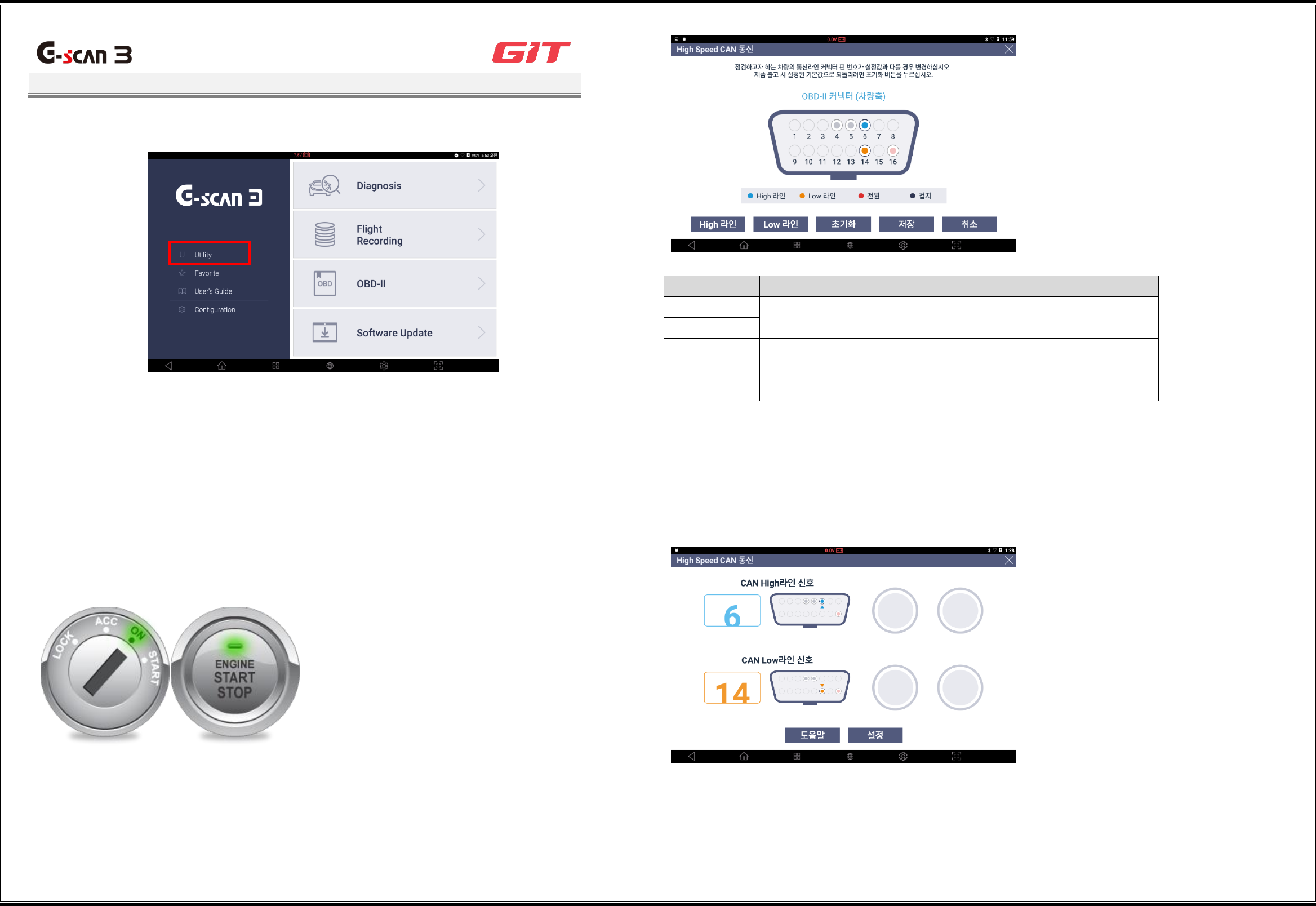
Utility
G3180203
On the initial window of G-scan3, clicking "Utility" will open the utility functions.
▌Communication Line Inspection
This measures the voltage changes in the communications line of the DLC cable, and displays
whether signals are received by on-off lighting. The on-off lights only indicate signal reception,
and do not indicate signal accuracy.
Driving condition
The start key of the vehicle should be in the "ON" position.
Setting of the communication line inspection function
The communication lines set for the OBD-II connector may vary depending on vehicles.
Therefore, refer to the maintenance guide of the vehicle, and set the communication line
according to the following guide before using the communication line inspection function.
Item
Description
High line
These enable changes in the setting of a selected
communication line.
Low line
Reset
This resets the communication line setting.
Save
This saves changed communication line setting.
Cancel
This cancels changed communication line setting.
High Speed CAN Communication
This enables an inspection of the high-speed CAN communication line. If the on-off display
does not run, check the driving condition (start key in the "ON" position) and the connector pin
number of the OBD terminal on the circuit diagram, and conduct a close check of the circuit.
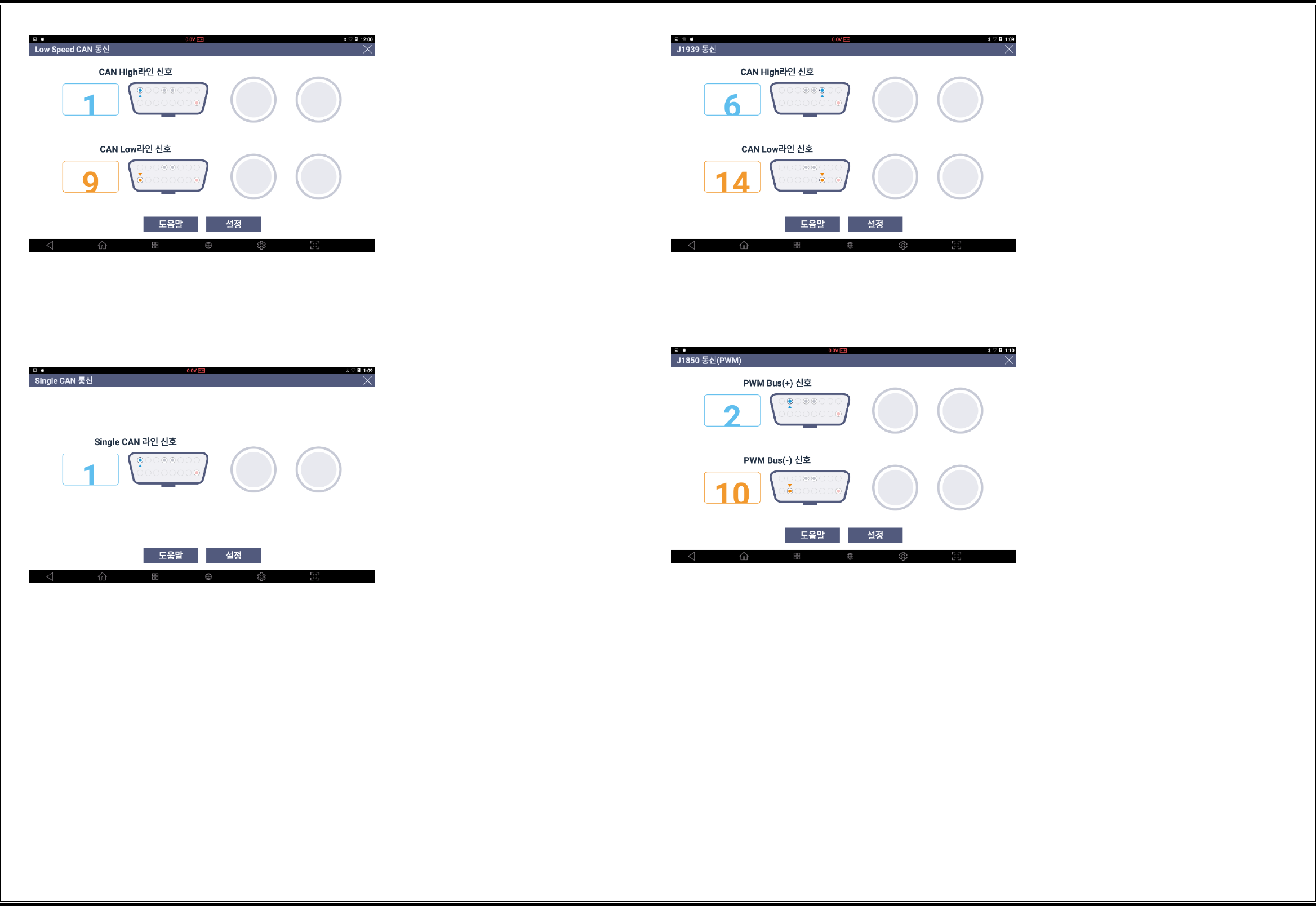
Low-speed CAN Communication
This enables an inspection of the low-speed CAN communication line. If the on-off display does
not run, check the driving condition (start key in the "ON" position) and the connector pin
number of the OBD terminal on the circuit diagram, and conduct a close check of the circuit.
30
Single CAN
This enables an inspection of the single CAN communication line. If the on-off display does not
run, check the driving condition (start key in the "ON" position) and the connector pin number of
the OBD terminal on the circuit diagram, and conduct a close check of the circuit.
J1939
This enables an inspection of the J1939 communication line. If the on-off display does not run,
check the driving condition (start key in the "ON" position) and the connector pin number of the
OBD terminal on the circuit diagram, and conduct a close check of the circuit.
J1850 (PWM)
This enables an inspection of the J1850 (PWM) communication line. If the on-off display does
not run, check the driving condition (start key in the "ON" position) and the connector pin
number of the OBD terminal on the circuit diagram, and conduct a close check of the circuit.
31
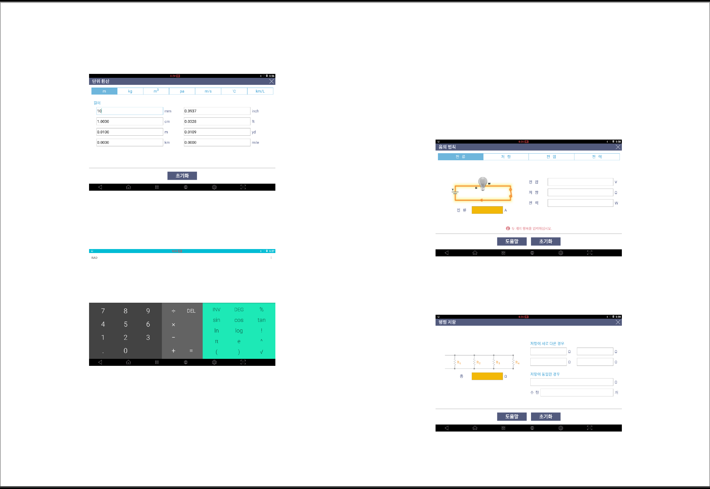
▌Unit Converter
This allows easy conversion of units such as length, weight, volume, pressure, velocity,
temperature, and fuel efficiency.
▌Calculator
This functions as a simple calculator.
Special Functions Calculator
This provides the special calculation functions including Ohm's law, parallel
resistance, frequency and period, tire distance per rotation, and percentage based
on defined calculation formulae.
Ohm’s Law
This calculates the necessary value when you enter two values from voltage, resistance, wattage,
and ampere identified for a circuit.
The necessary value is the item that is selected on the top categories.
Parallel Resistances
This calculates the overall resistance value when you enter the values of parallel-connected
resistors.
32
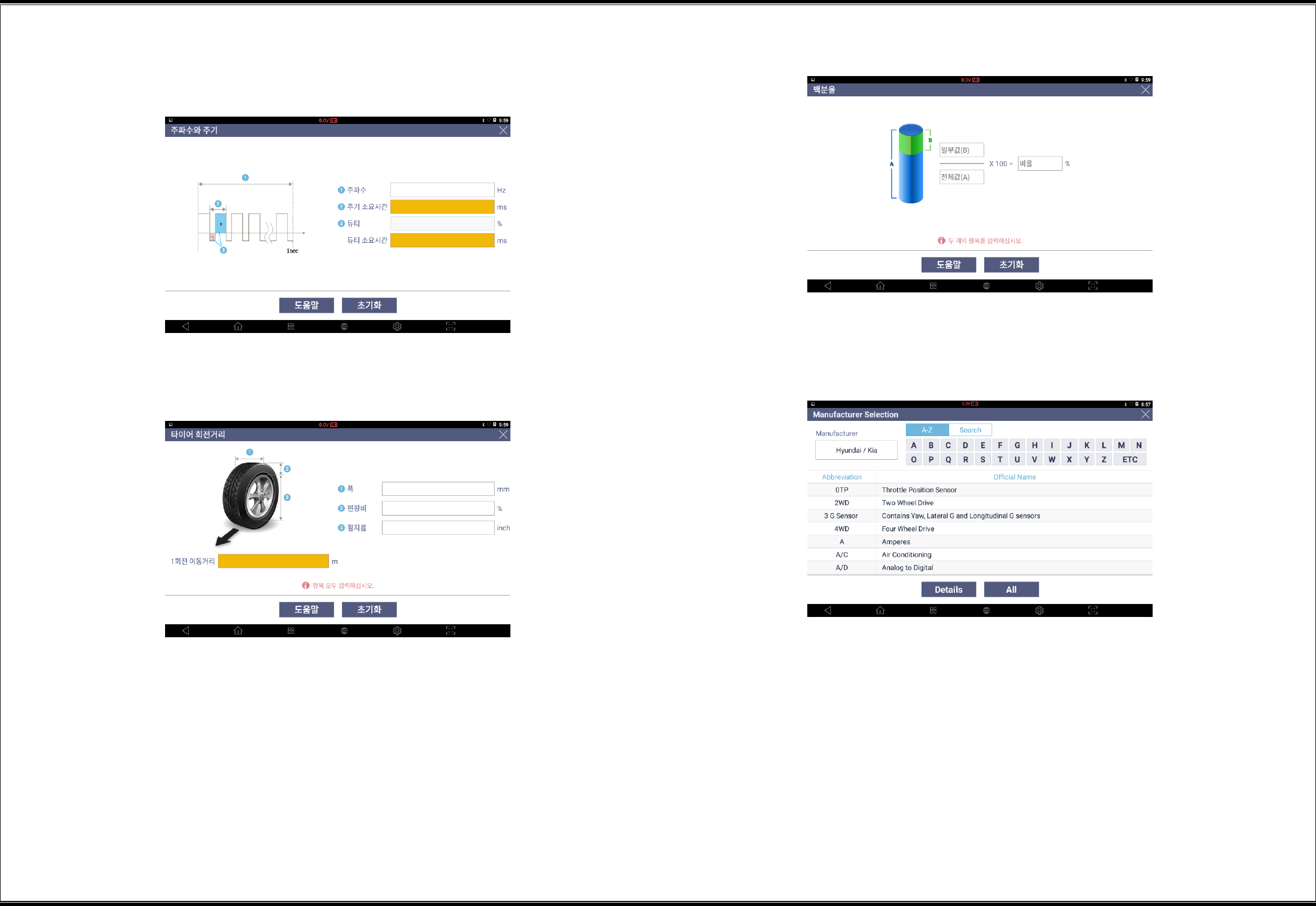
Frequency and Period
This calculates required frequency time and required duty (+) time when you enter the values of
frequency and duty.
Tire Distance per Rotation
This calculates the moving distance per rotation of a tire when you enter the tire data.
Percentage
▌Abbreviation Dictionary
This enables the search of the full definition of the abbreviations used by automakers.
33
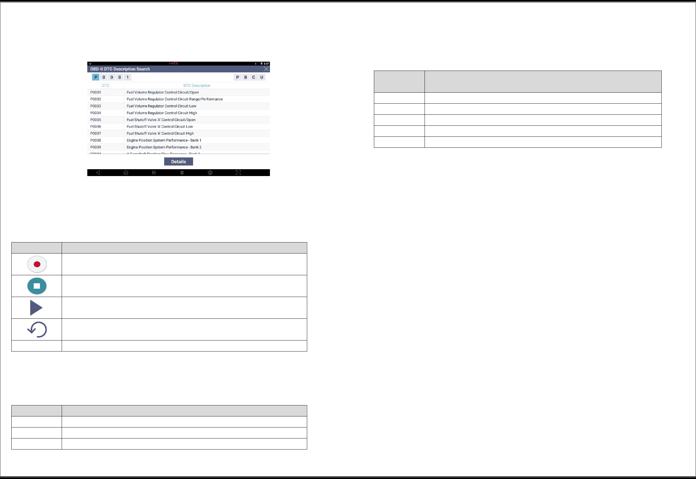
▌OBD-II DTC Description Search
This enables a description search of OBD-II DTCs.
▌Voice Recorder
This enables recording of voice data through the microphone embedded in the G-scan3 terminal.
Button shape
Description
This starts recording in a voice recording standby mode.
This stops recording while voice recording is in progress.
This plays recorded data.
This changes to the voice recording standby mode.
SAVE
This saves recorded voice data in a file.
▌Camera
This enables saving of images in files through the camera embedded in the G-scan3 terminal.
Button shape
Description
This takes an image with the camera.
This saves an image in a file.
This changes to the camera standby mode.
▌Video
This enables saving of videos in video (MP4) files through the camera and the microphone
embedded in the G-scan3 terminal.
Button
Shape
Description
This takes a video with the camera.
This stops video recording.
This saves a video in a file.
This plays a recorded video.
This changes to the camera standby mode.
34
Specifications
G3180203
G-scan3 & Tablet PC specification information. For additional optional components, please refer
to the separate specificatioin sheet or GIT homepage.
Category
Specifications
OS
Android 6.0
CPU
Exynos 7420 Octa core @2.1GHz
Memory
Internal Flash 64GB / RAM 3GB
LCD
10.1” TFT / 1280 x 800 pixel
Touch Screen
Capacitive Touch Screen
Camera
Rear : 13M Pixel / AF / Flash Light
Wireless Connection
802.11 a/b/g/n , Bluetooth 4.1, Wi-Fi direct.
External Memory
Micro-SD card slot ( max. 128GB )
Vehicle Interface
CAN (High speed, Low speed, Single), ISO-9141,
ISO-9141-CARB, KWP-2000, SAE-J1708, SAE-J1587,
J1850(PWM/VPW), Melco Pull-Down
External Device
* TPMS : Internal mounting support / not support
External Key
3ea (Power/Function1/Function2 Key)
Audio
Speaker (mono), Mic, Earjack
Sensors
Gyro-sensor, Accelation Sensor
DC Input
DC 9 ~ 30V
Battery Capacity
Li-ion Polymer / 6,300mAh(3.7V) / Hard Pack
Size (W x L x T), Wg
304 x 210 x 40mm, 1.6Kg

35
Appendix
36
Disposal of Old Electrical and
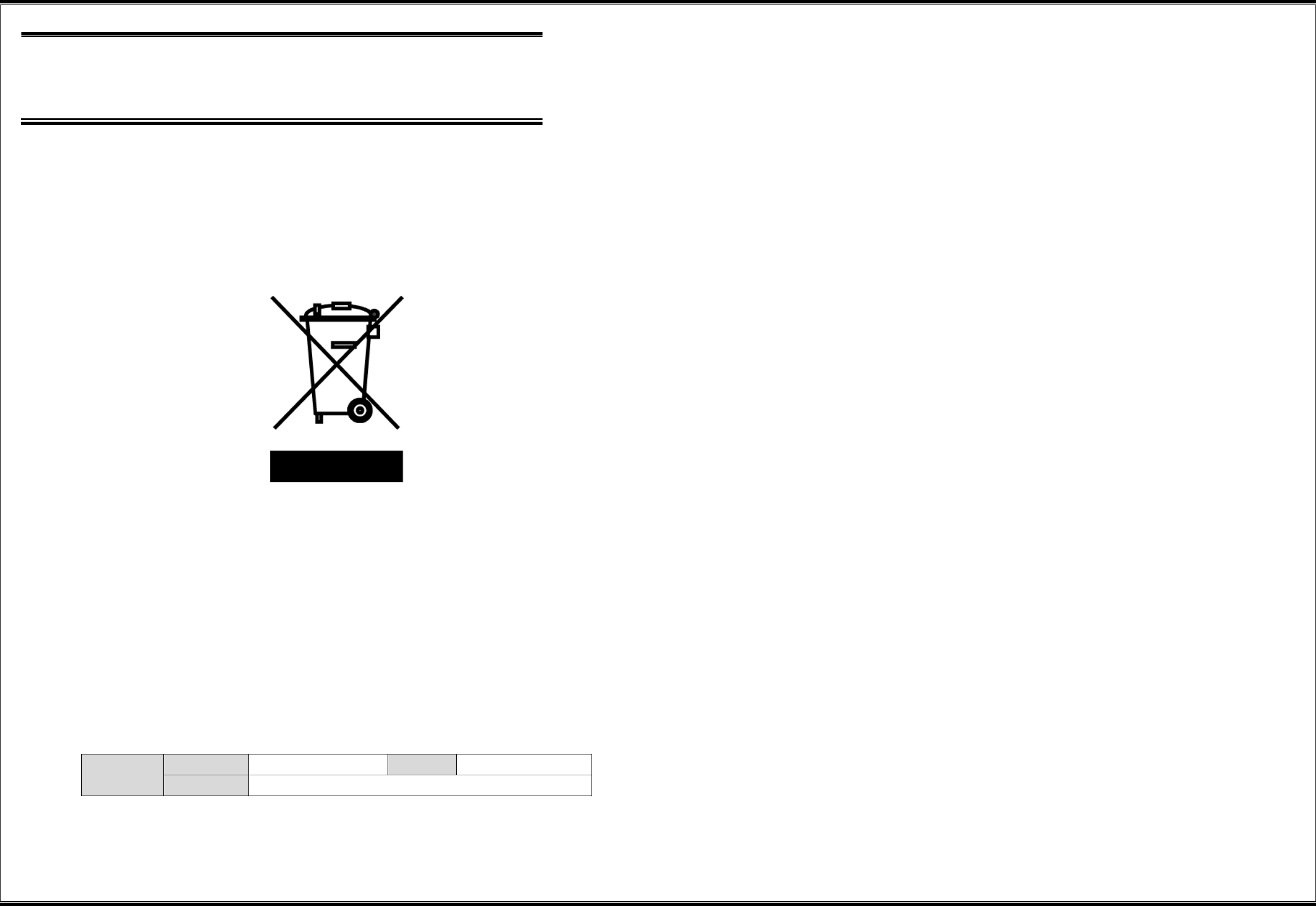
Electronic Equipment
WEEE (Waste Electrical and Electronic Equipment) symbol shown in [Figure 1] is indicated on the back of the G-s
can3 main module.
Please follow the regulation guide for disposal of Waste Electrical and Electronic Equipment. Use caution disposi
ng of the Trigger module; it contains a lithium battery. Users must follow the regulations when replacing or disc
arding this battery.
Fig. 1. WEEE Symbol
Disposal of Old Electrical & Electronic Equipment (Applicable in the European Union and other European countrie
s with separate collection systems)
This symbol on the product or on its packaging indicates that this product shall not be treated as household wa
ste. Instead it shall be handed over to the applicable collection point for the recycling of electrical and electronic
equipment. By ensuring this product is disposed of correctly, you will help prevent potential negative consequen
ces for the environment and human health, which could otherwise be caused by inappropriate waste handling of
this product. The recycling of materials will help to conserve natural resources. For more detailed information ab
out recycling of this product, please contact your local city office, your household waste disposal service or the
shop where you purchased the product.
Manufacturer Information
Manufacturer
Company
GIT Co., Ltd
TEL
82-2-1588-3665
Address
05655, GIT Bldg, 87, Macheon-ro, Songpa-gu, Seoul, Korea
RF SPEC
Frequency Band
WLAN
2 412 ~ 2 472 MHz
5 180 ~ 5 240 MHz / 5 190 ~ 5 230 MHz
Bluetooth
2 402 ~ 2 480 MHz
125 kHz
Output Power
WLAN
2.4 GHz
802.11b : 13.5 dBm ± 1 dB
802.11g : 11.5 dBm ± 1 dB
802.11n_HT20 : 11.0 dBm ± 1 dB
5 GHz
802.11a : 12.5 dBm ± 1 dB
802.11n_HT20 : 12.0 dBm ± 1 dB
802.11n_HT40 : 12.0 dBm ± 1 dB
Bluetooth
GFSK : 7.0 dBm ± 1 dB
π/4DQPSK : 2.5 dBm ± 1 dB
8DPSK : 2.5 dBm ± 1 dB
Bluetooth LE
1 dBm ± 1 dB

37
This device complies with Part 15 of the FCC Rules. Operation is subject to the following two conditions: (1) this
device may not cause harmful interference, and (2) this device must accept any interference received, including i
nterference that may cause undesired operation.
CAUTION : Any Changes or modifications not expressly approved by the manufacturer could void the user's auth
ority to operate the equipment. This equipment has been tested and found to comply with the limits for a Class
B digital device, pursuant to part 15 of the FCC Rules. These limits are designed to provide reasonable protectio
n against harmful interference in a residential installation. This equipment generates, uses and can radiate radio
frequency energy and, if not installed and used in accordance with the instructions, may cause harmful interferen
ce to radio communications. However, there is no guarantee that interference will not occur in a particular instal
lation. If this equipment does cause harmful interference to radio or television reception, which can be determine
d by turning the equipment off and on, the user is encouraged to try to correct the interference by one or more
of the following measures:
• Reorient or relocate the receiving antenna.
• Increase the separation between the equipment and receiver.
• Connect the equipment into an outlet on a circuit different from that to which the receiver is connected.
• Consult the dealer or an experienced radio/TV technician for help.
A minimum separation distance of 20 cm must be maintained between the antenna and the person for this appli
ance to satisfy the RF exposure requirements.
This transmitter must not be co-located or operating in conjunction with any other antenna or transmitter unless
authorized to do so by the FCC.