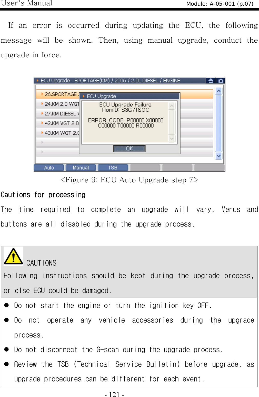
G I T G1PDDMN001 Scan Tool User Manual
G.I.T Co.,Ltd. Scan Tool Users Manual
UserManual.wiki
>
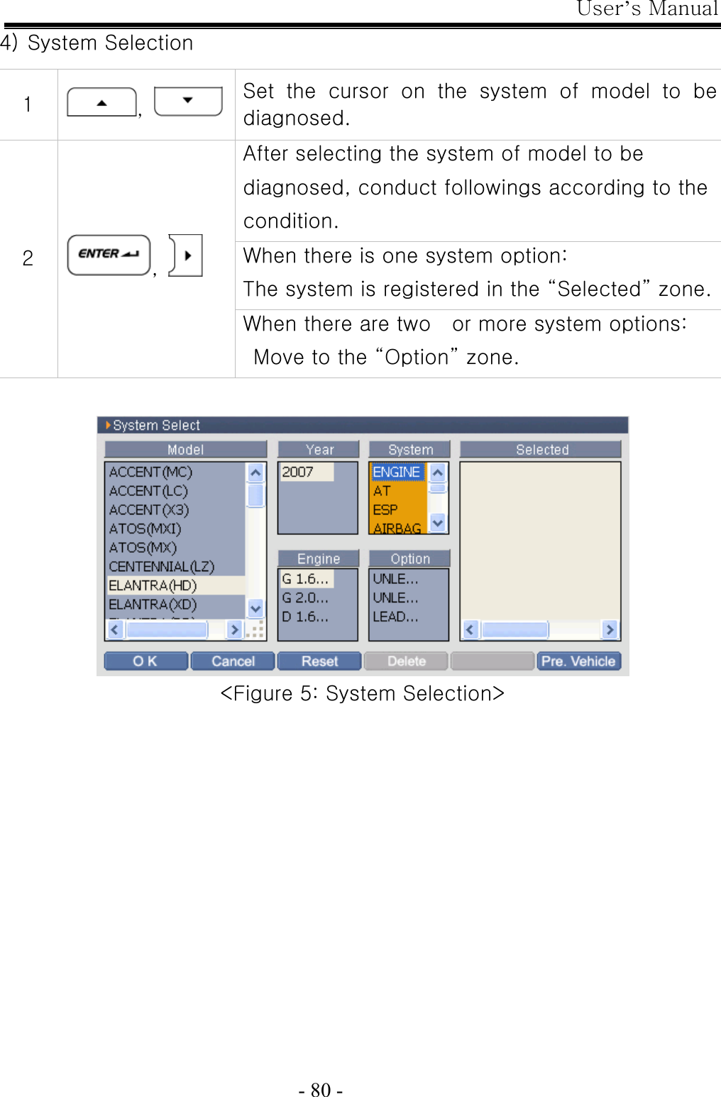
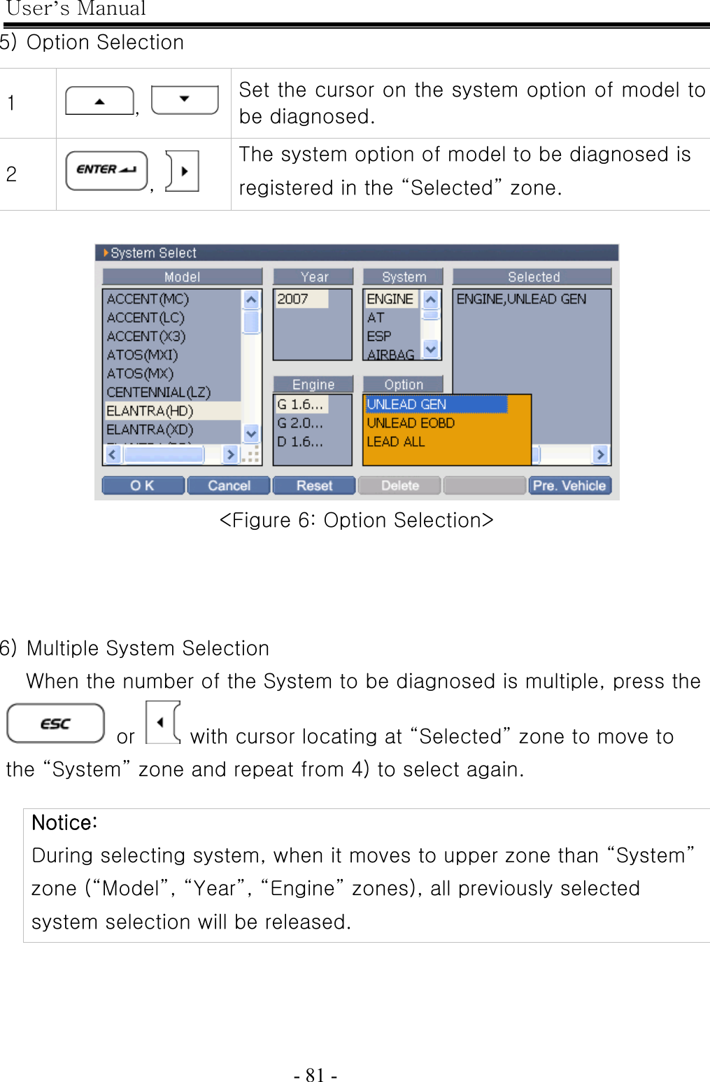
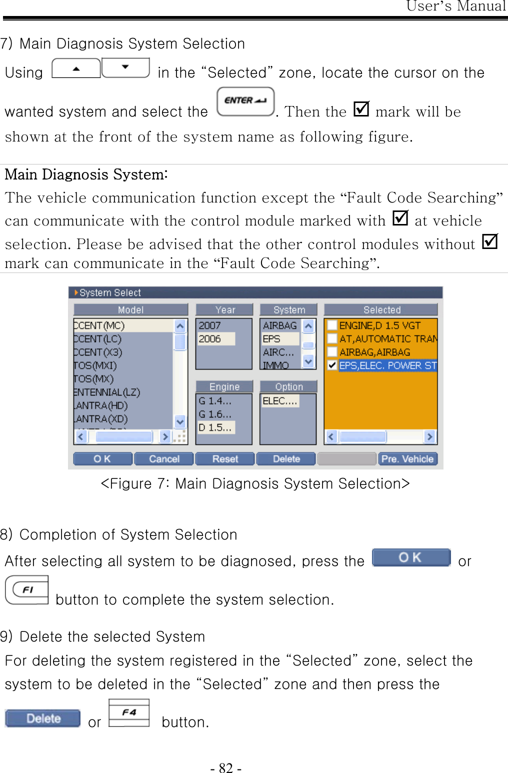
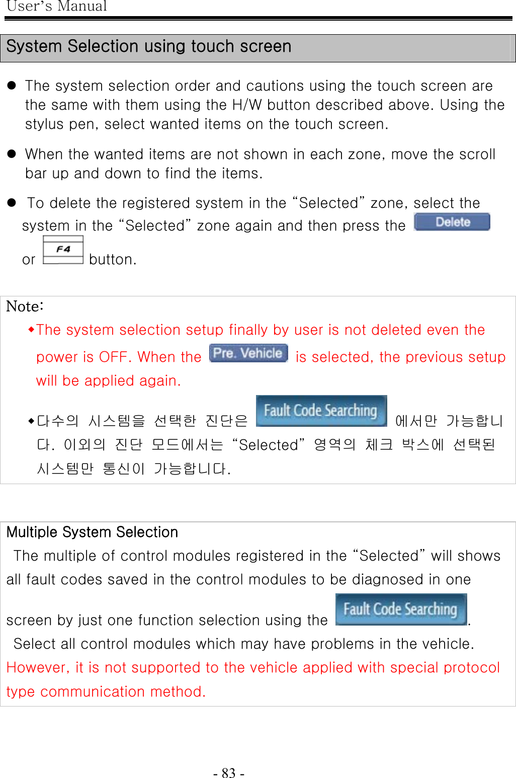
G I T
>
G1PDDMN001 User Manual
Users Manual
Navigation menu
Upload a User Manual
Namespaces
Wiki Guide
HTML
PDF
Info
Views
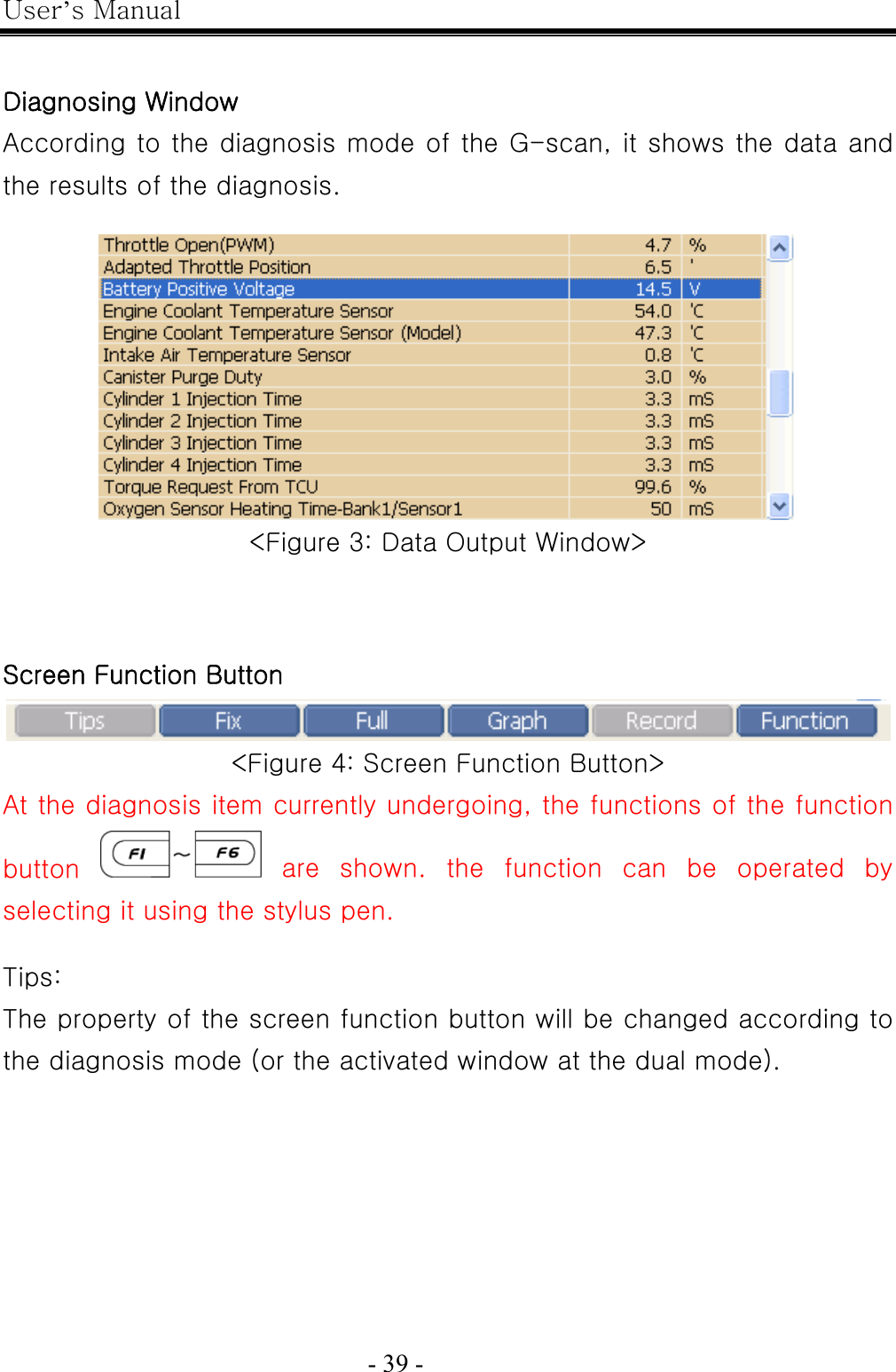
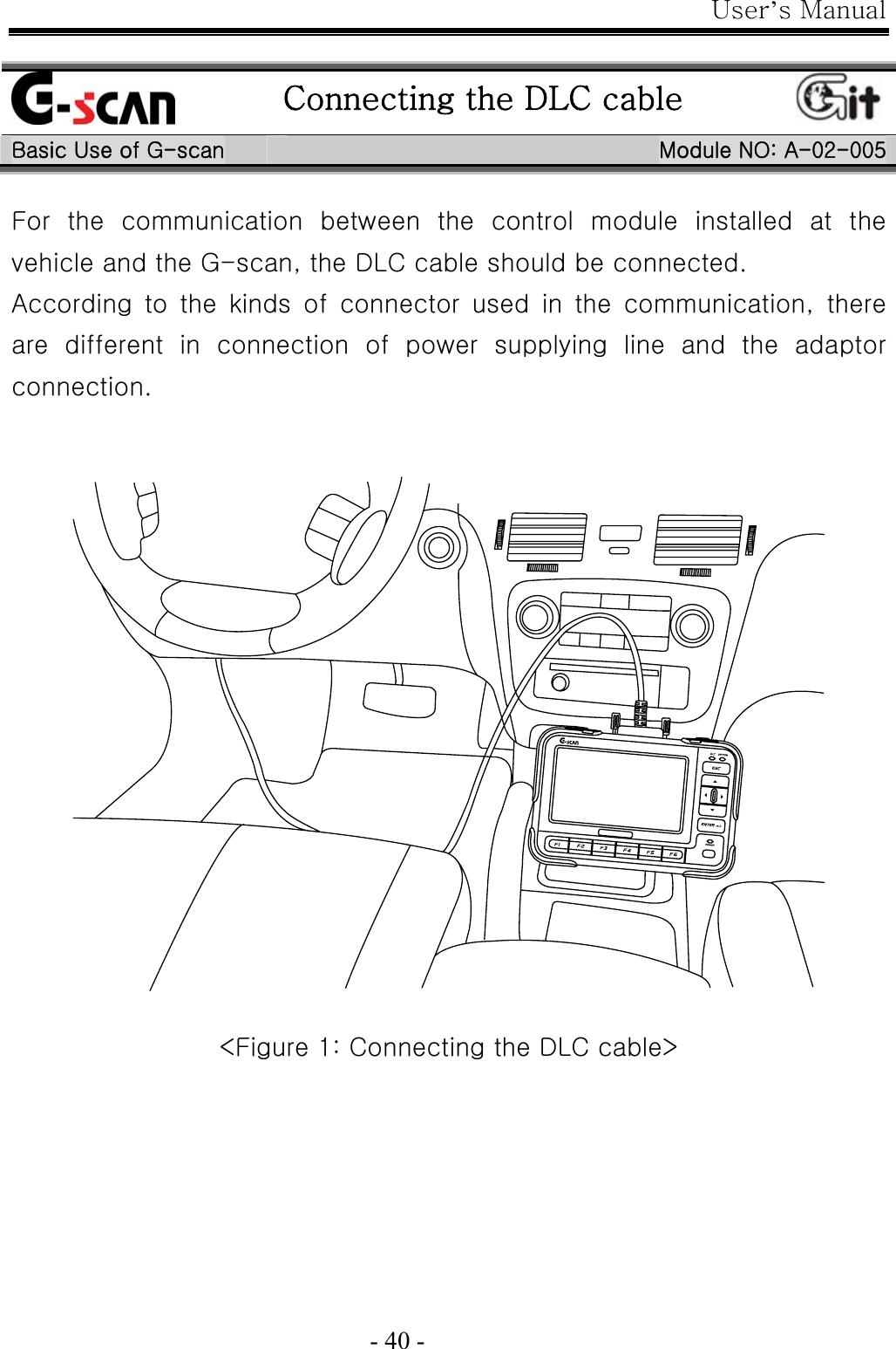
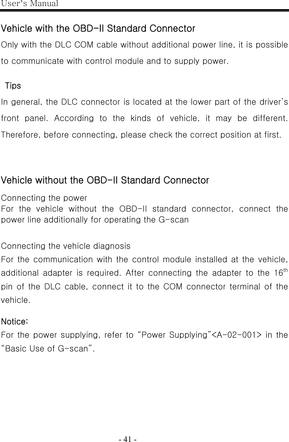
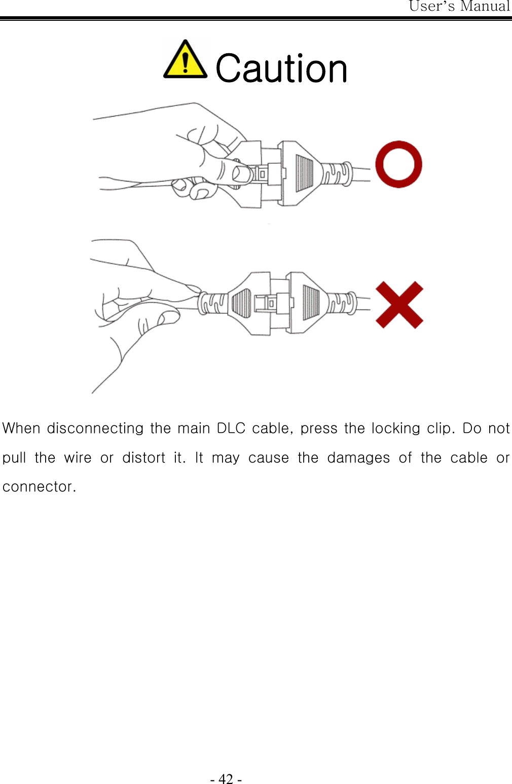
User Manual
Discussion / Help
Navigation

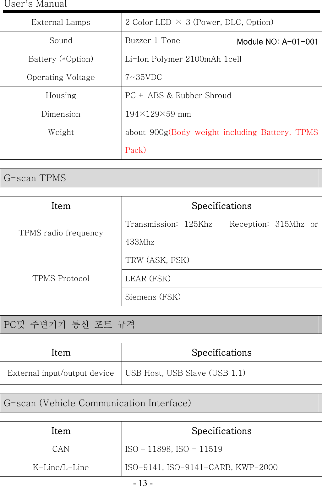
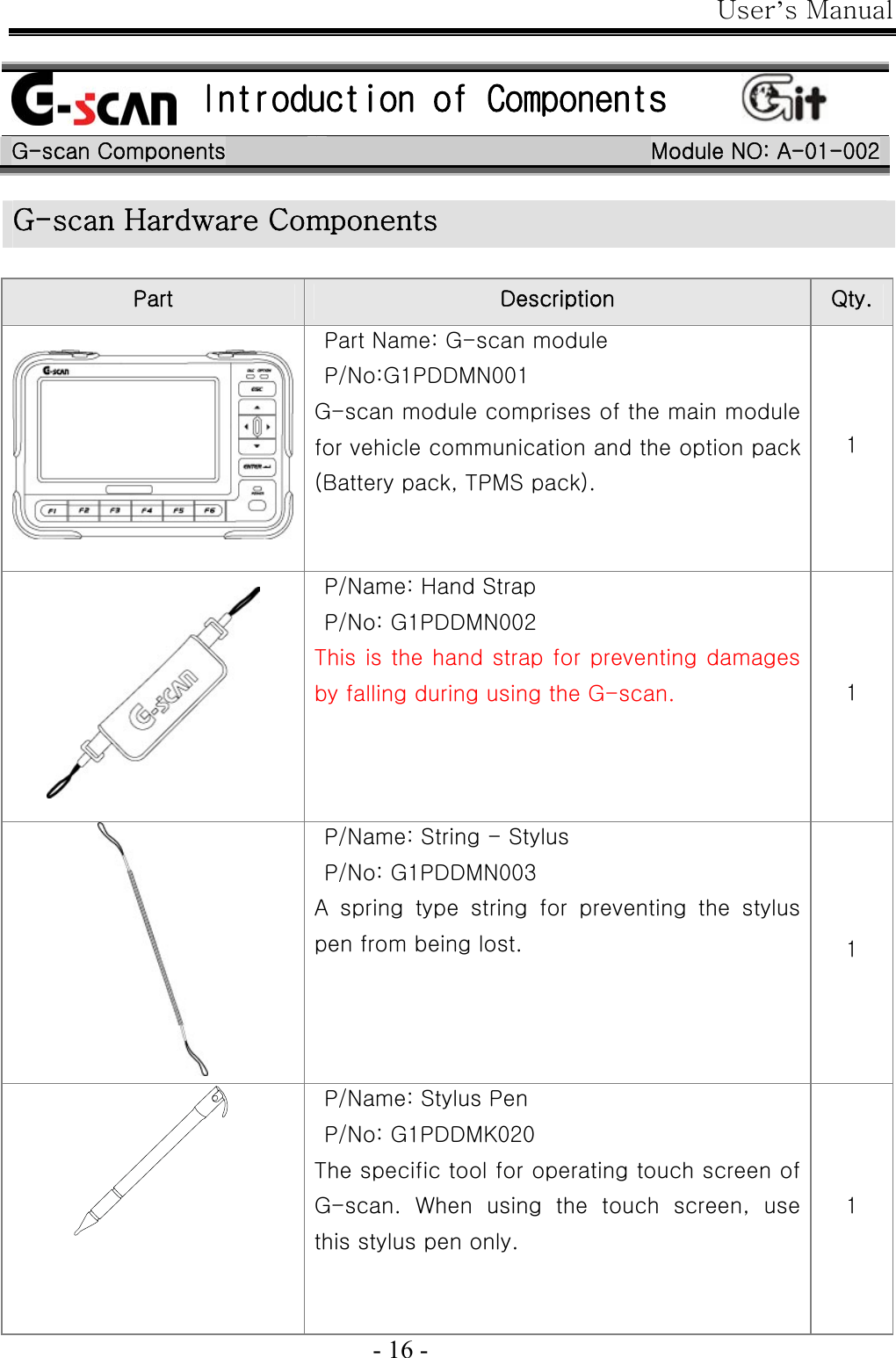
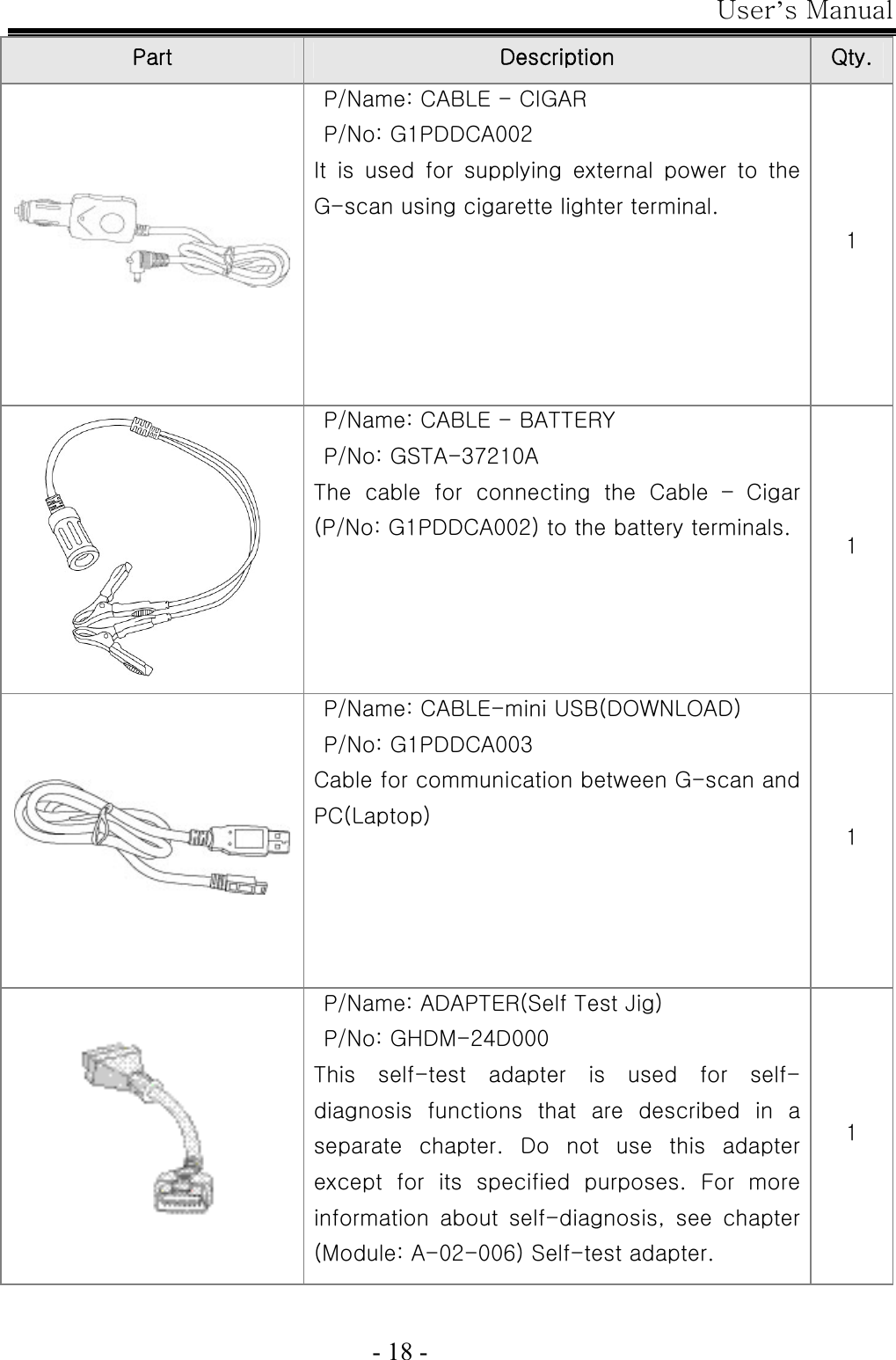
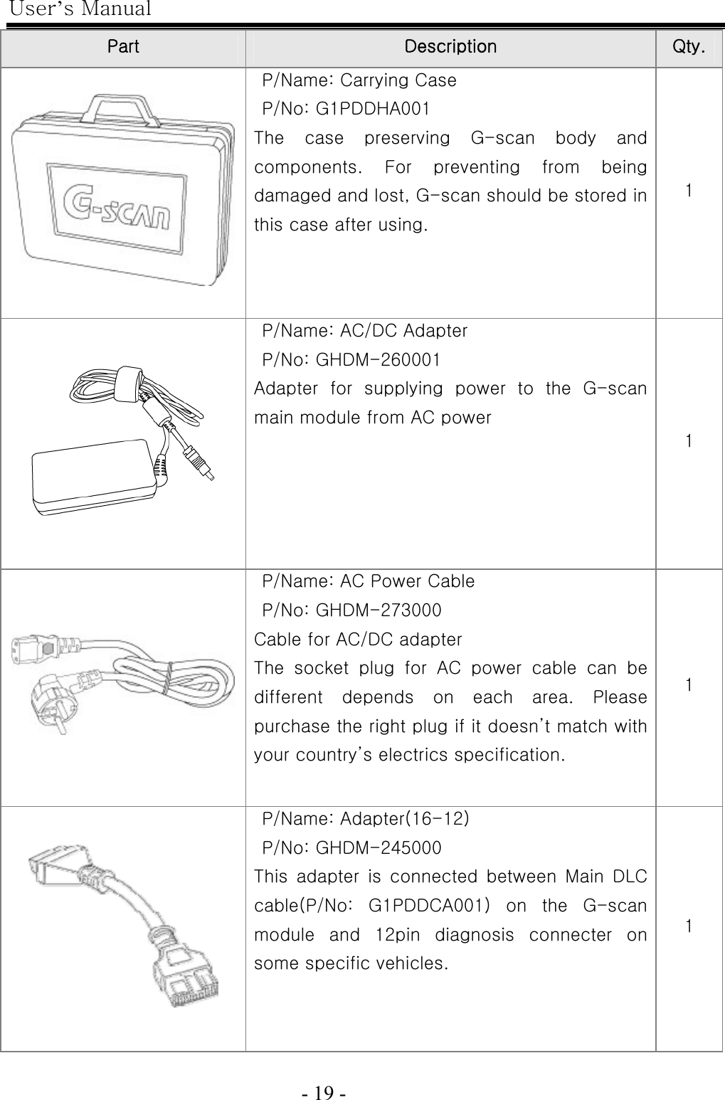
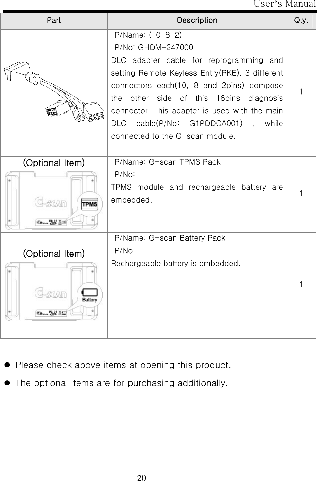
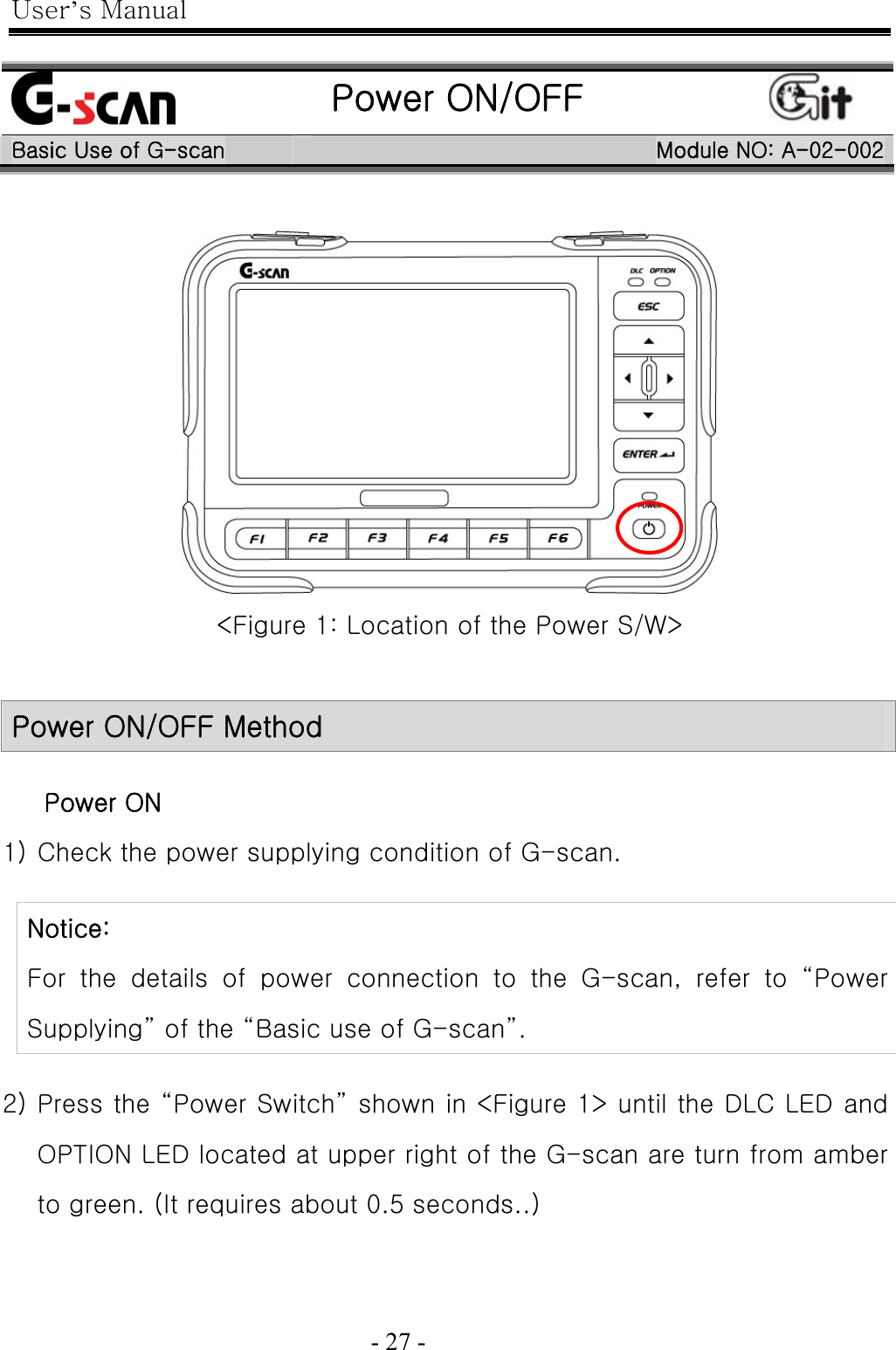
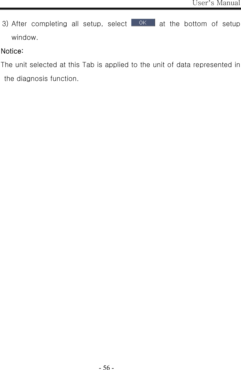
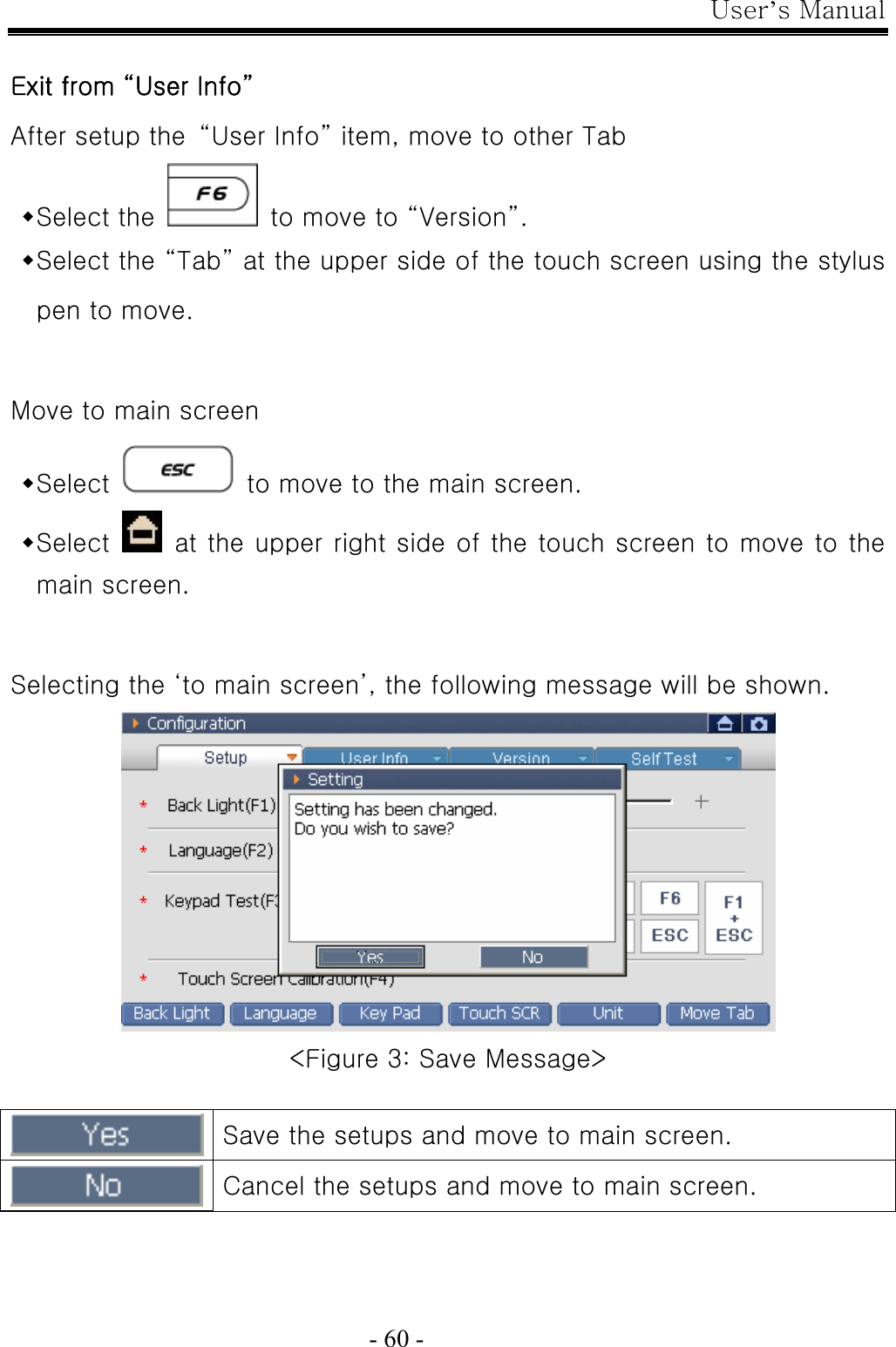
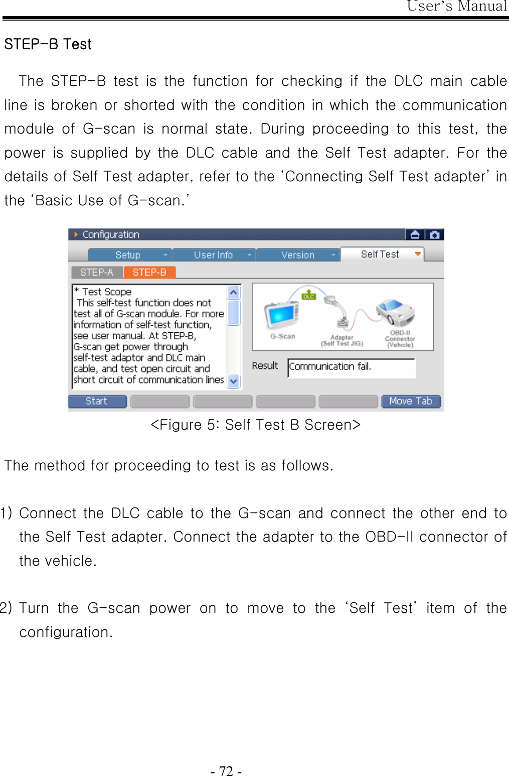
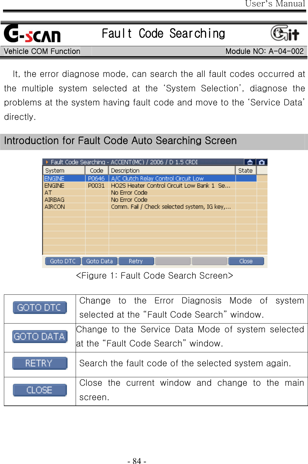
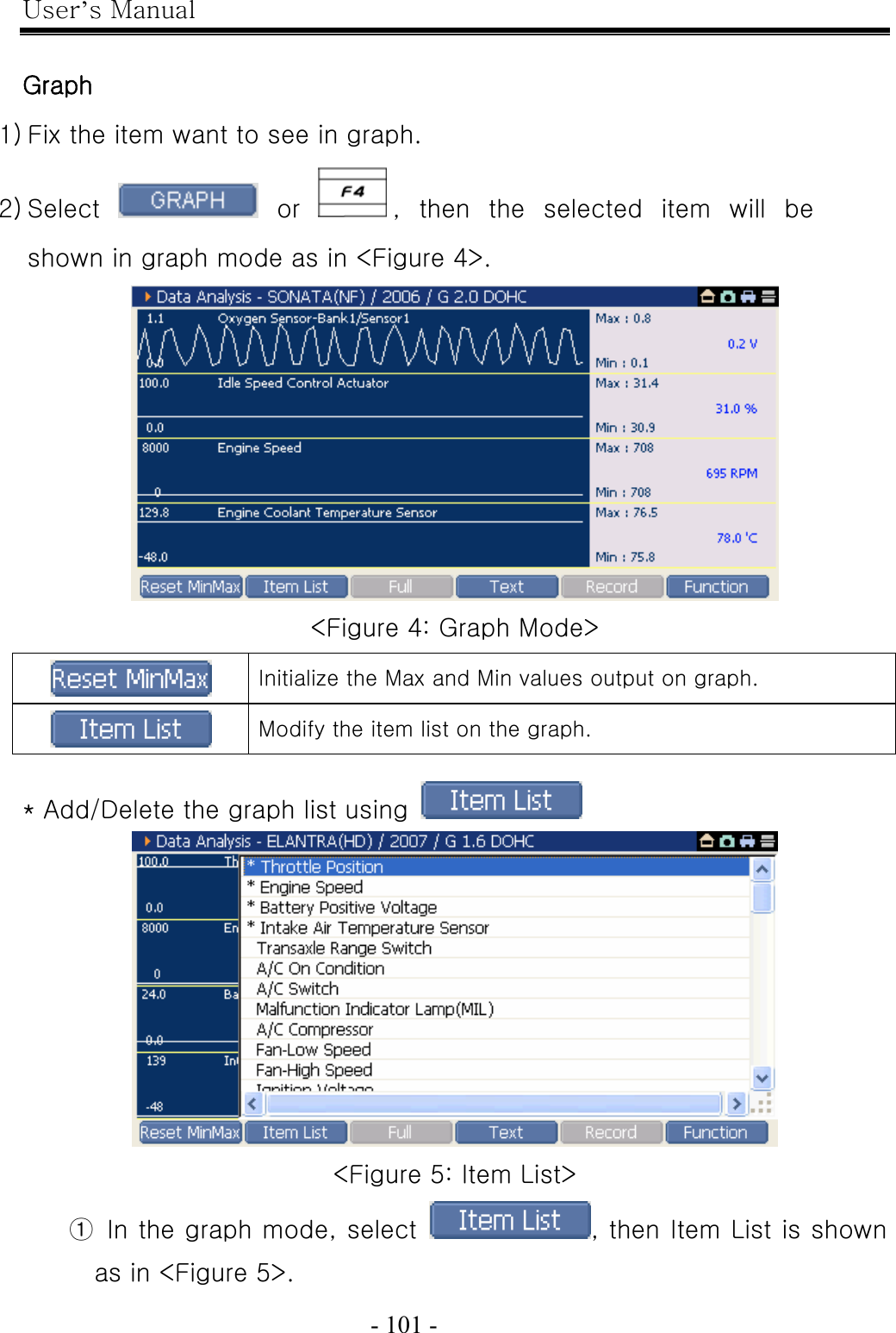
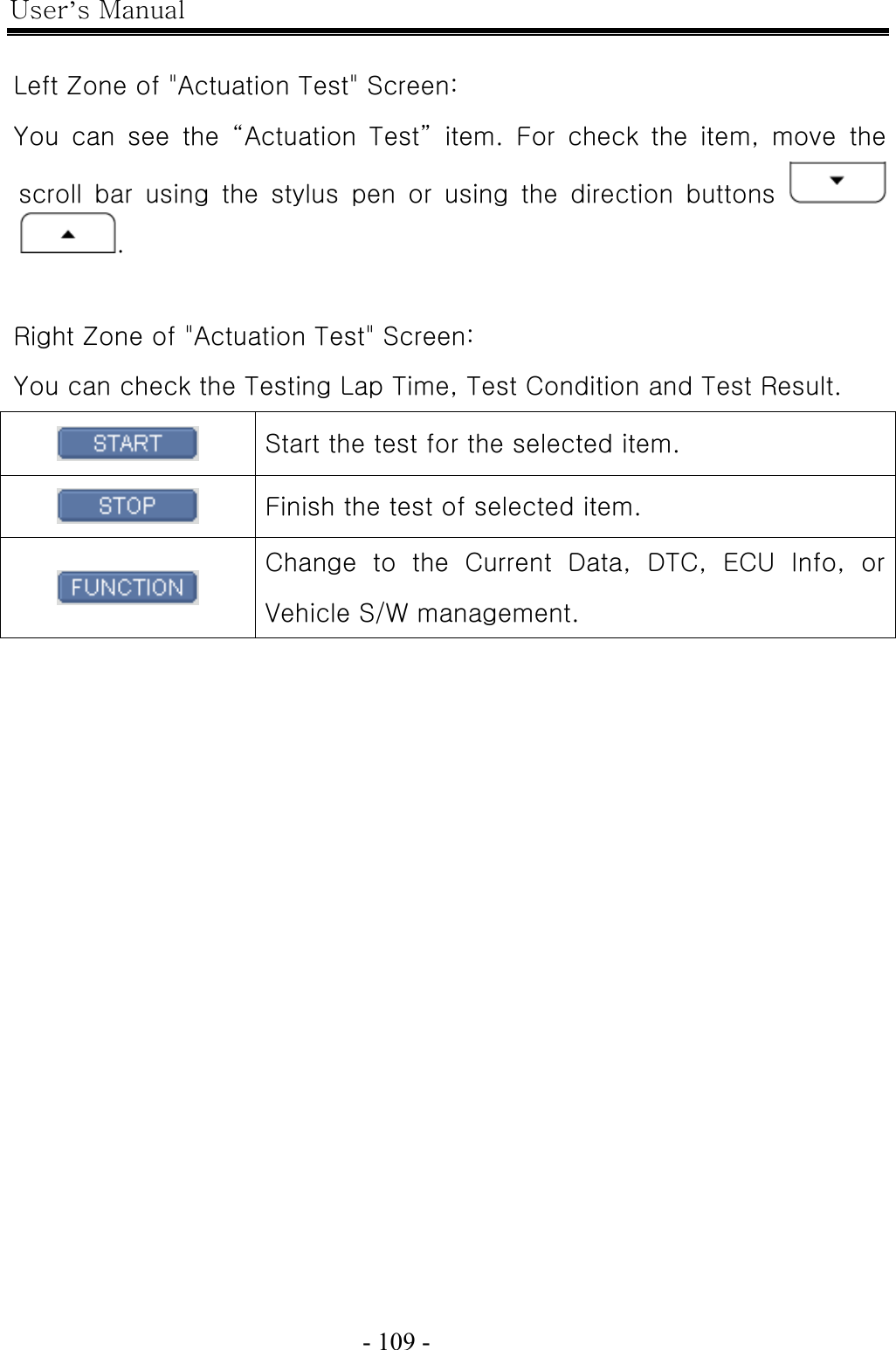
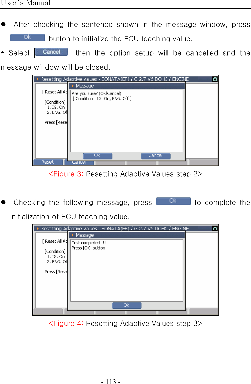
![User’s Manual - 17 - Part Description Qty. P/Name: CABLE-DLC P/No: G1PDDCA001 DLC main cable for communication between G-scan module and (16 pin) OBD-II diagnosis connector on vehicle. 1 P/Name: User’s Manual P/No: N/A The book describing the basic information for using the G-scan. 1 촬영 필요 P/Name: CD (S/W) P/No: N/A CD includes the PC utility program. The PC utility supports the G-scan update and the G-scan system recovery. 1 P/Name: Adapter[16pin-20pin(R)] P/No: GHDM-244000 DLC Adapter cable [16pin to 20pin(R)] for Main DLC cable (P/No: G1PDDCA001) and 20-pin diagnosis connector on vehicle. 20pin (R) connector is GRAY in color. 1](https://usermanual.wiki/G-I-T/G1PDDMN001/User-Guide-782364-Page-17.png)

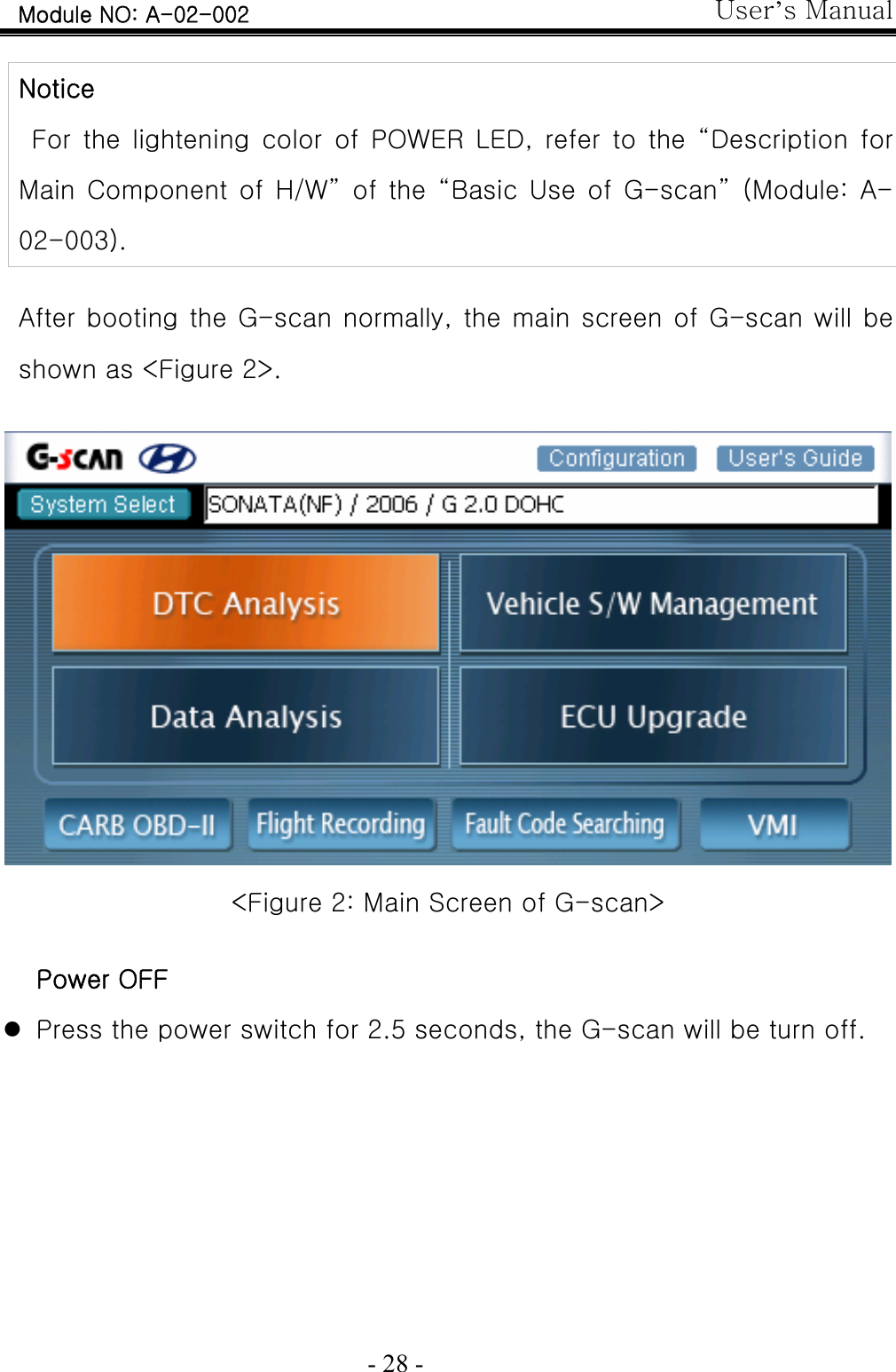
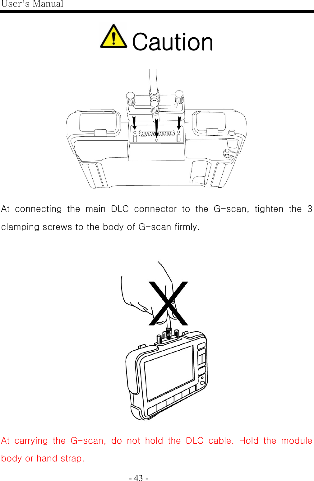
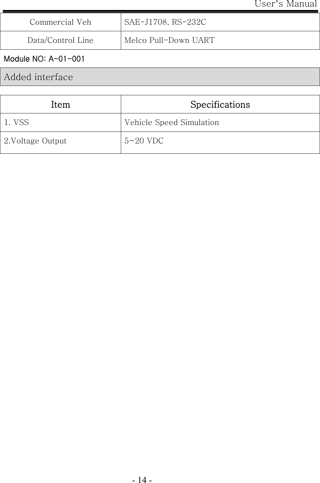
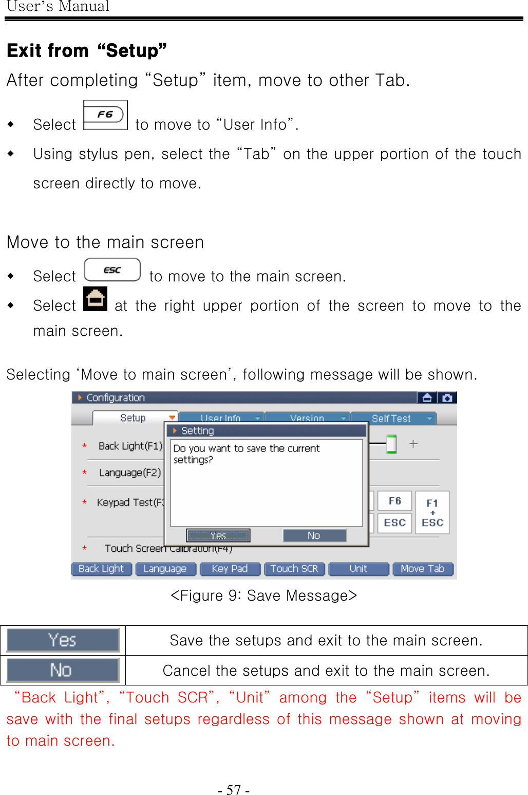
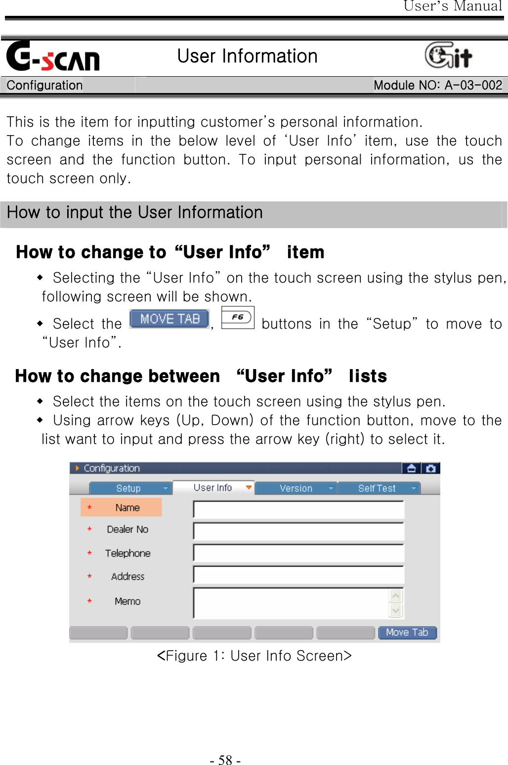
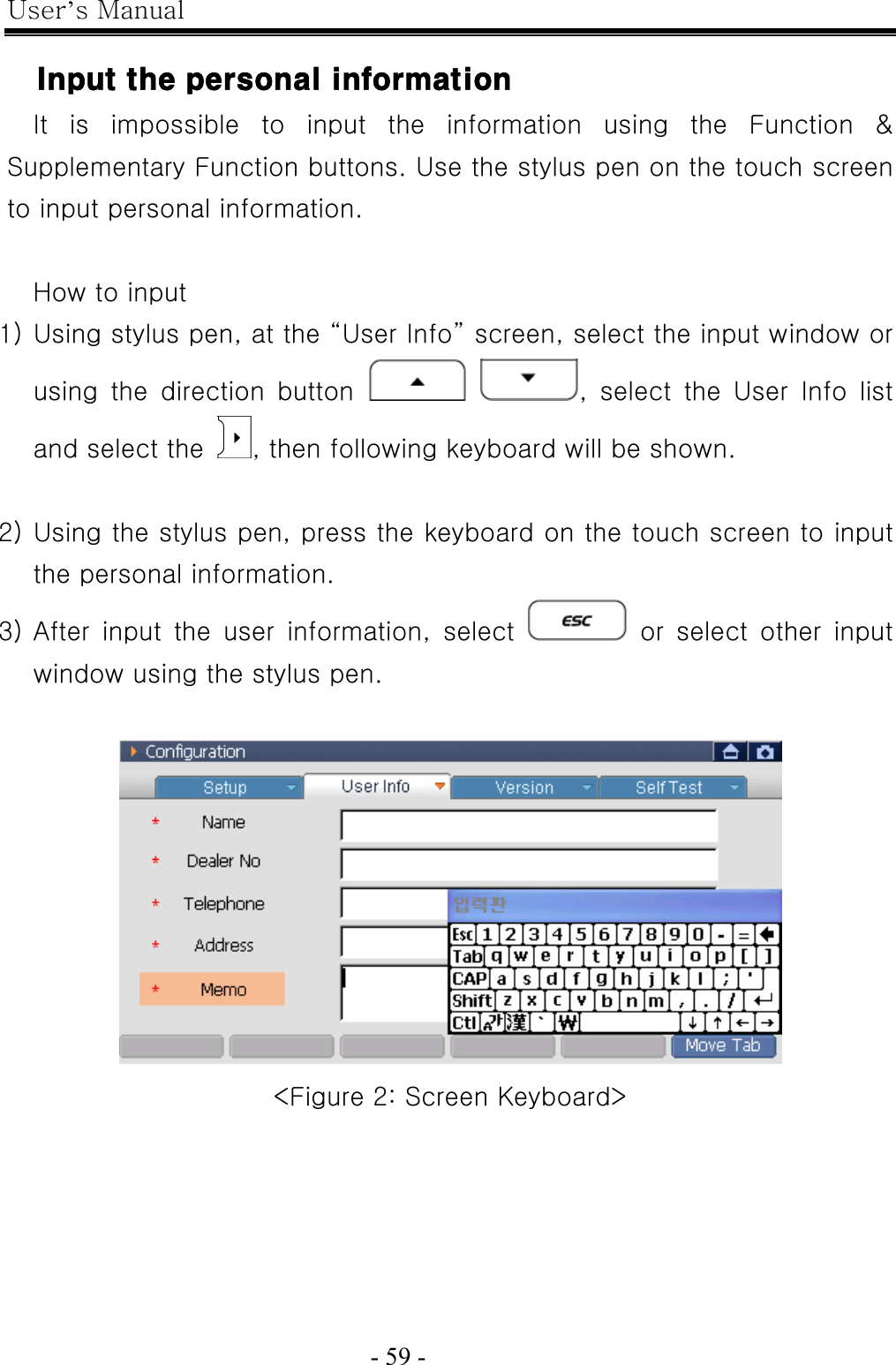
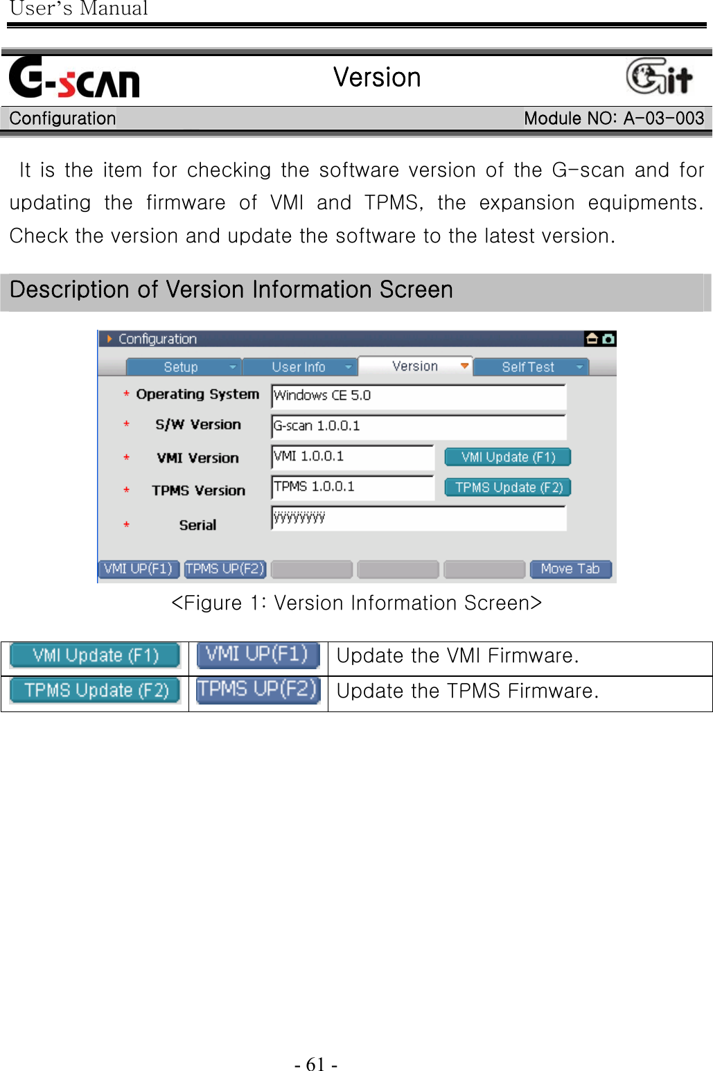
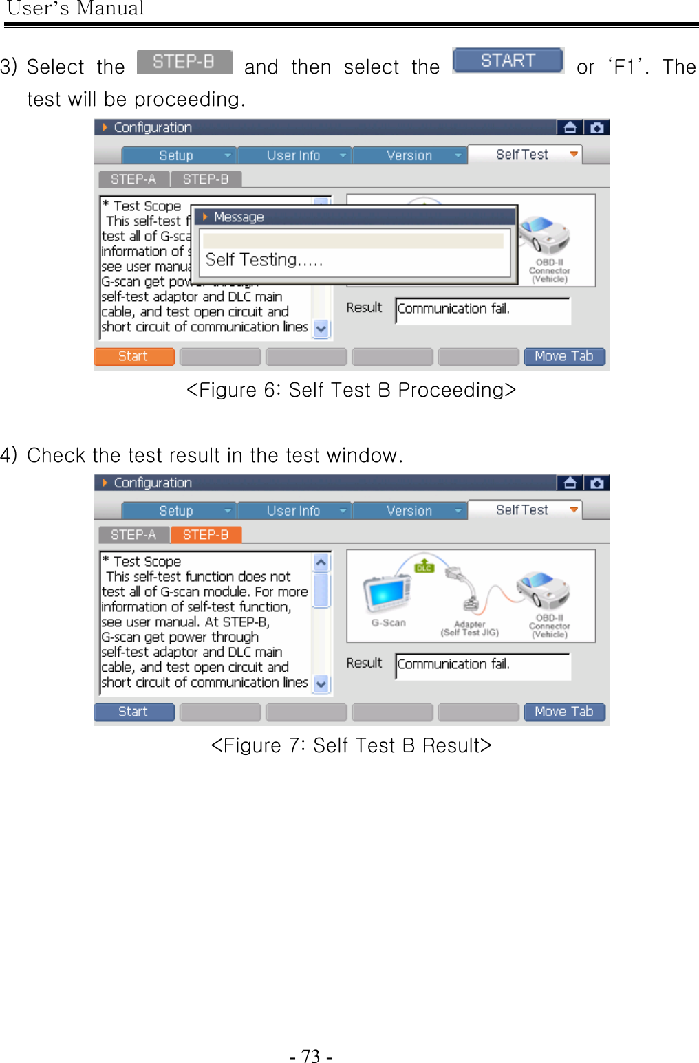
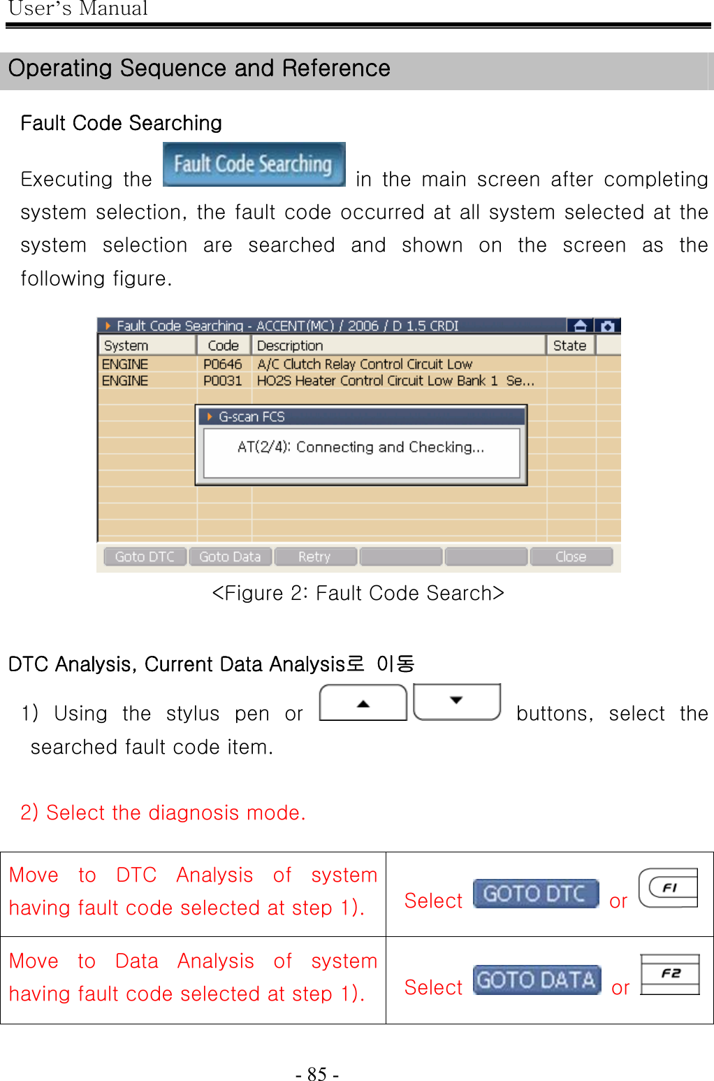
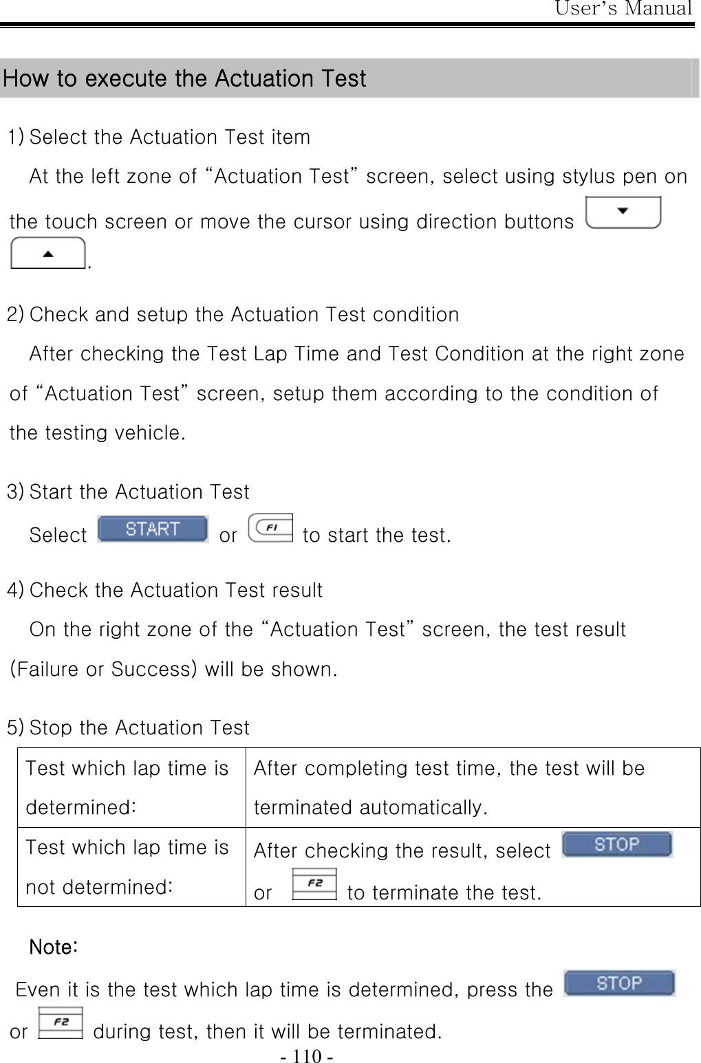
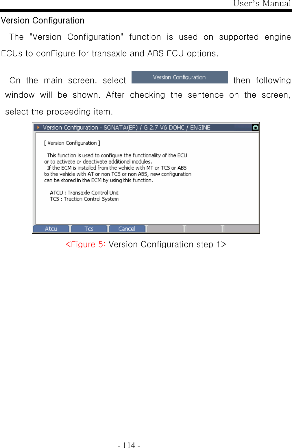
![User’s Manual - 46 - Before performing the self-test function, connect the Main DLC cable (P/No: G1PDDCA001) between G-scan module and Self-test adapter (P/No: GHDM – 24D000). Then, connect the other side of Self-test Adapter to the OBD-∥ Connector on the vehicle as shown in [Figure1]. Figure 1. Installation of the Self-test adapter After installing the adapter, follow the instructions as indicated on the Self-Test screen located on the Configuration menu. Connecting the Self-Test Adapter (GHDM – 24D000) Module: A–01-003 (p.02)](https://usermanual.wiki/G-I-T/G1PDDMN001/User-Guide-782364-Page-46.png)
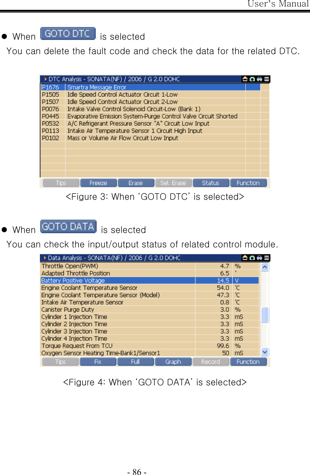

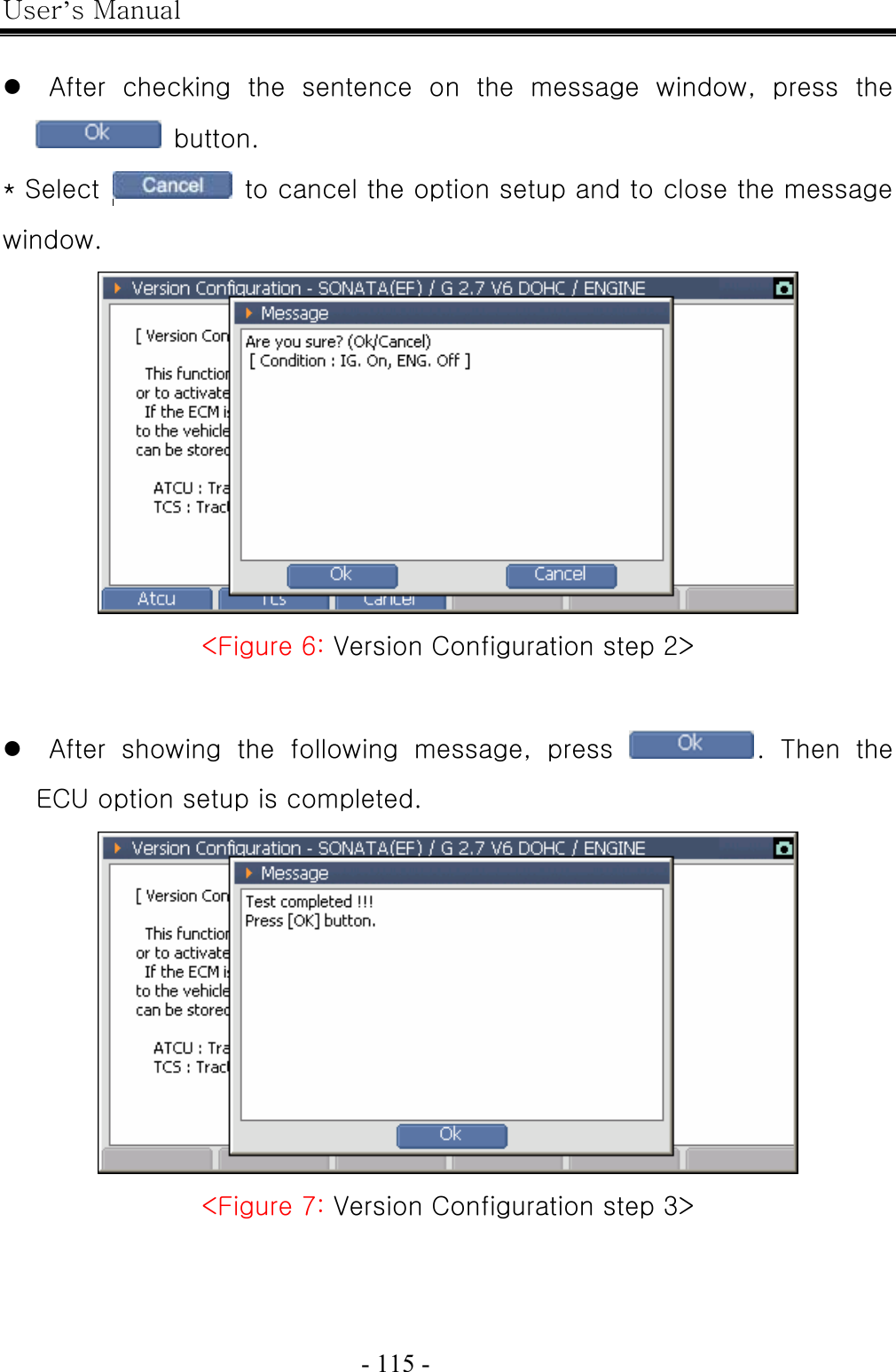
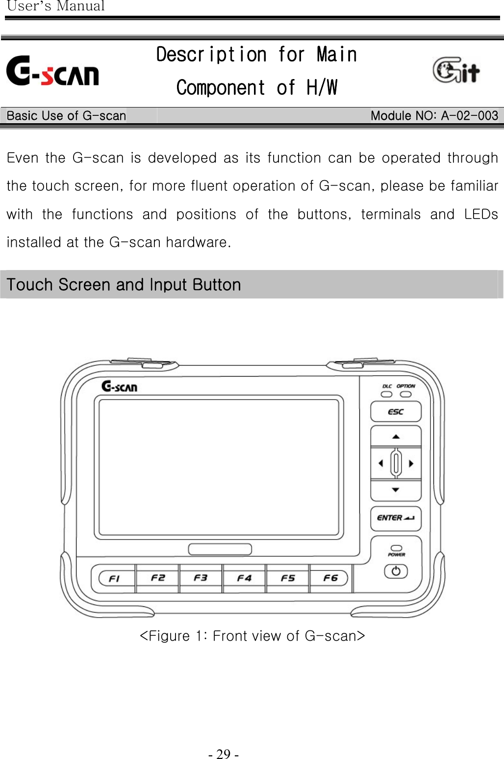
![User’s Manual - 134 - Disposal of Old Electrical and Electronic Equipment WEEE (Waste Electrical and Electronic Equipment) symbol shown in [Figure 1] is indicated on the back of the G-scan main module Please follow the regulation guide for disposal of Waste Electrical and Electronic Equipment. [Figure 1] WEEE Symbol Disposal of Old Electrical & Electronic Equipment (Applicable in the European Union and other European countries with separate collection systems) This symbol on the product or on its packaging indicates that this product shall not be treated as household waste. Instead it shall be handed over to the applicable collection point for the recycling of electrical and electronic equipment. By ensuring this product is disposed of correctly, you will help prevent potential negative consequences for the environment and human health, which could otherwise be caused by](https://usermanual.wiki/G-I-T/G1PDDMN001/User-Guide-782364-Page-134.png)