User Manual

GDS User’s Manual
1
G |
Before Use
Read the instructions thoroughly for proper operation of your GDS M.
This manual contains information needed for using GDS M.
The manual is subject to change without prior notice.
Git assumes no liability for the Application which GIT do not produce
GDS M application includes the several functions for uploading and downloading data. GIT assumes
no liability for the fee due to the use of data
Safety Warning and Caution before Use
This section contains WARNING and CAUTION for safe usage of GDS M. Before use, the user
should read the following information.
WARNING
This indicates incorrect handling may result in a major accident involving death or
serious injury.
The VCI should be secured in a safe location when operating the vehicle to avoid interference with
other vehicle equipment.
Only use the specified adapters and cables when connecting the VCI module. (7~35VDC)
Ensure all cables are properly connected during operation. Do not disconnect communication cable
or power cables unless finished with the equipment.
When using the trigger module, ensure that the module is installed in a safe and secure location to
avoid interference with other vehicle equipment.
Do not disassemble the VCI module.
Use only genuine accessory parts supplied by GIT.
Never connect the device to equipment rather than vehicles.
Products are to be stored within the right temperatures. (Refer to CAUTION)

2
G |
CAUTION
This indicates incorrect handling may lead to injury or damage to property. Under
certain conditions more serious consequences may result.
Do not remove the rubber shield from the VCI. Keep liquids and other contaminants away from the
VCI.
Do not drop the VCI.
Do not place any objects (tools, manuals, etc.) on the VCI.
Observe correct polarity when connecting the battery supply extension cable.
When connecting cables under the hood, secure the cables to avoid damage caused by hot or
moving parts. Unplugging the DLC and USB cables from the VCI module must only be done after
releasing the cable connector lock tap(s).
USB cable must be connected to VCI module in order to upgrade any vehicle ECU or VCI firmware.
Properly store all components when not in use.
Do not use cables as carrying handles.
Do not store products in places where;
Extremely high or low temperature (Refer to feature of products)
Extremely high or low humidity (Refer to feature of products)
Inside a vehicle during summer season for a long time
Exposed to direct rays
Avoid a shock or vibrations or under heavy weight.
Avoid a shock or vibrations during shifting.
Keep products away and store from moisture.
GIT is not responsible for those causes that are generated by PCs, which are not recommended by
GIT.
Keep products away from flammable substances or places where fierce static electricity can occur.
Products and accessories are not to be coated or painted with chemical substances or acid that can
corrode the equipment.
Do not expose the equipment to X-ray or Microwave. This might cause severe damage to the
equipment.

3
G |
Thank you for purchasing the Global Diagnostic System (GDS). Read the instructions thoroughly for
proper operation of your Global Diagnostic System
This Manual is copyrighted by Global Information Technology Co., Ltd. All rights reserved. No part of
this manual may be reproduced in any form without the prior written permission of Global Information
Technology Co., Ltd.
No patent liability is assumed with respect to the use of the information contained herein.
ⓒ2005 Global Information Technology Co., Ltd. All Right Reserved.
Global Diagnostic System specifications and manual are subject to change without notice. Global
Information technology Co., Ltd. assumes no liability for damage incurred directly or indirectly from
error, omission or discrepancies between the Tablet PC, VCI, TPMS and the User Manual.
Introduction
Copyright
Disclaimer

4
G |
Introduction
5
G |
Hardware
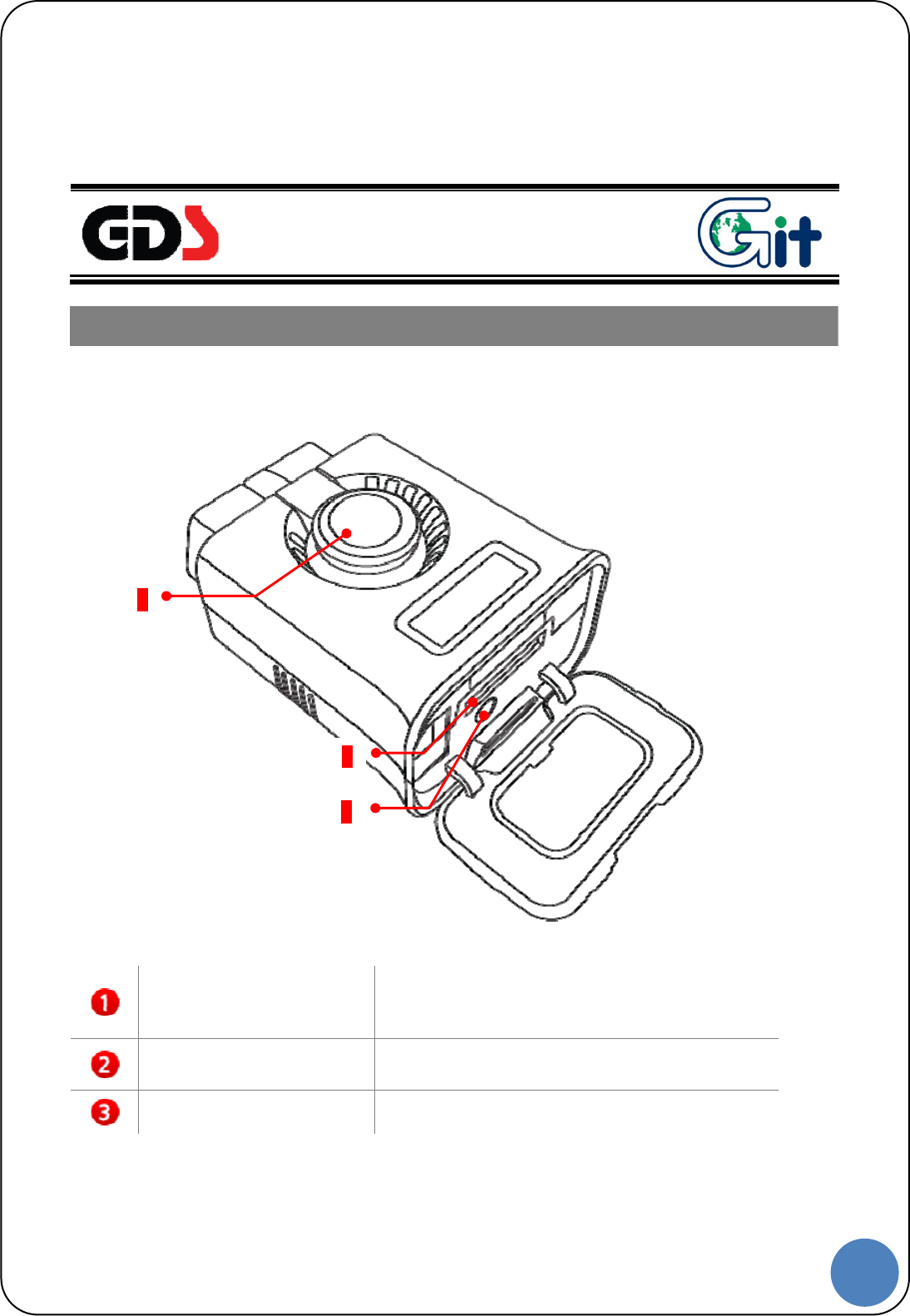
VCI-Ⅱ Component Identification and Functions
VCI Ⅱ Unlock button
Unlock button for the pairing. When
disconnecting VCI Ⅱ from OBD-II(16Pin) on the
vehicle side, unlock the pairing between .
External Connector for
USB cable
Communication port for Connecting between VCI
Ⅱ and GDS PC with wire USB cable
Bluetooth Paring Reset
Button
Reset button for re-pairing with Bluetooth GDS
Trigger
1
2
3
6
G |
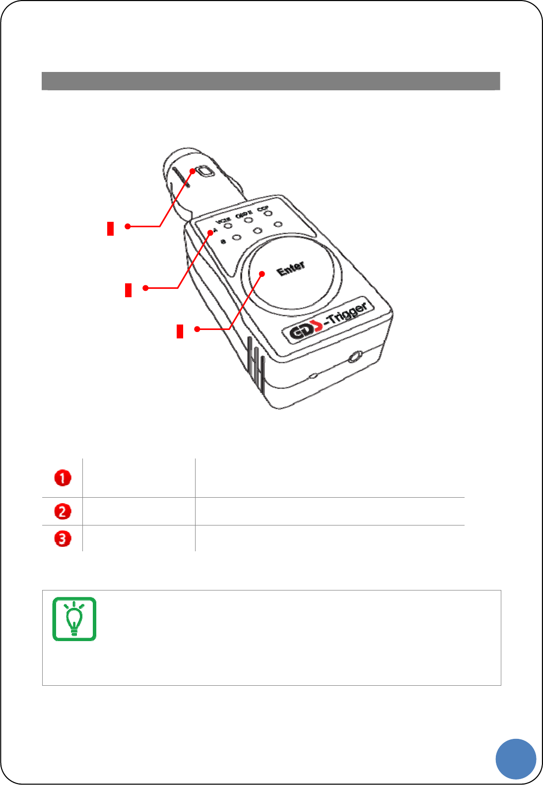
GDS Trigger Component Identification and Functions
Trigger Cigar Lighter
connector
Supplies the power to the GDS Trigger, should be
connected to the Cigar Lighter on the vehicle
Trigger Status LED Indicates VCI Ⅱ communication status.
Trigger Enter Button When using Trigger manually, the color of lights
indicates the current status of trigger module.
Notice
Bluetooth Trigger Module must be inserted to Cigar Lighter when it is used for flight
record (saving ECU input/output data on the vehicle)
1
2
3
7
G |
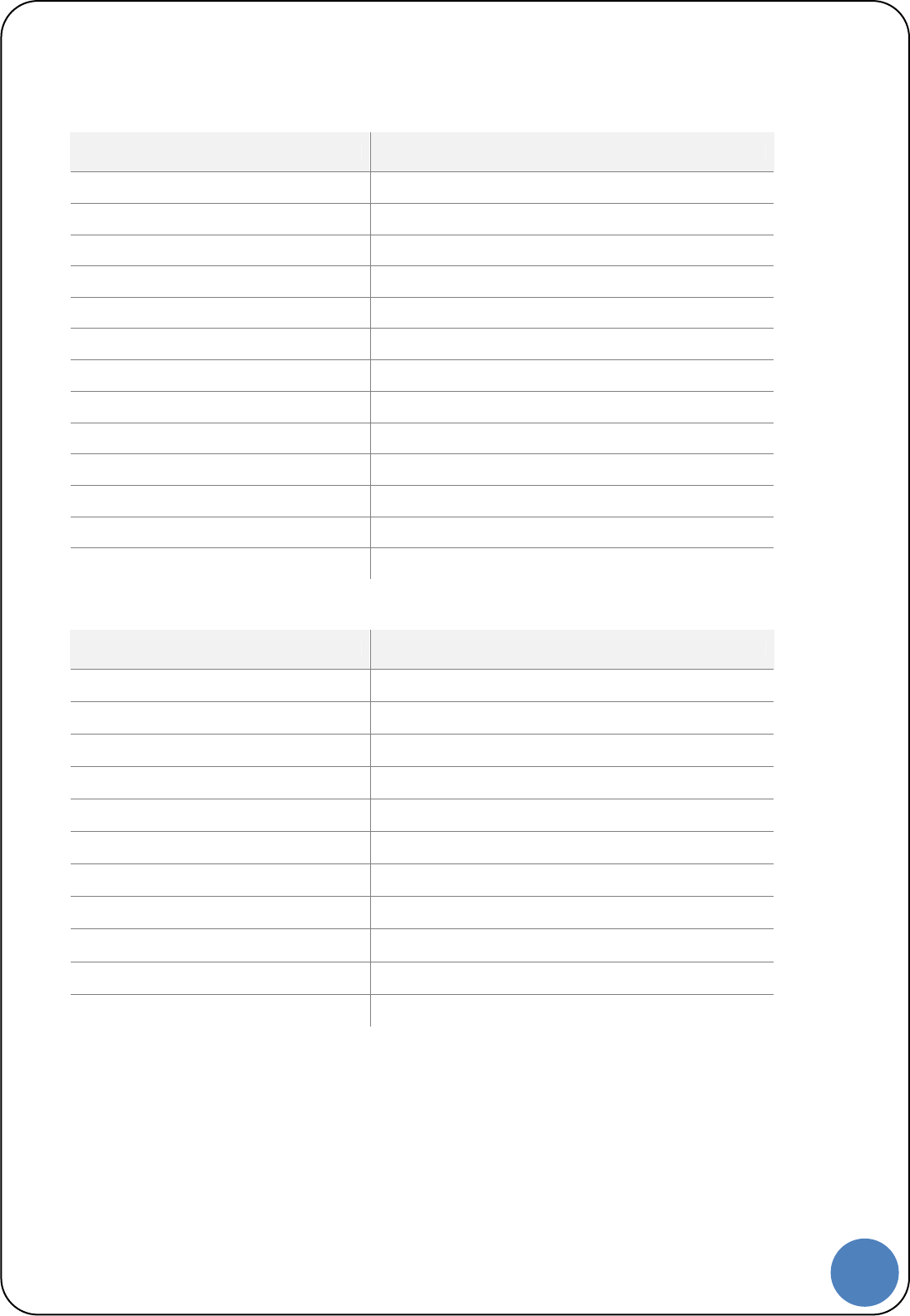
VCI Ⅱ Specifications Information
Item Specifications
CPU ARM 32-bit Cortex™-M3 (STM32F207VGT6) @ 120 MHz
Memory Flash Memory 1MByte, SRAM 128KByte
Operating Voltage 7 VDC to 35 VDC
Operating Temperature -20 ℃ to 60 ℃
Storage Temperature -40 ℃ to 85 ℃
Operating humidity 20 %R.H. to 90 %R.H.
Current Consumption Standby Mode 300 mA @ 12 V
Wire Protocol USB 2.0 Full Speed(12Mbps)
Wireless LAN Protocol Wireless LAN IEEE 802.11 a/b/g/n(20)
Bluetooth Protocol Bluetooth 3.0, 2.1 (Class 1)
Dimension 57.9 × 73.6 × 35.9 mm
Weight 90 g
Case PC+ABS
GDS Trigger Specifications Information
Item Specifications
CPU ARM 32-bit Cortex™-M3 (STM32F205RGT6) @ 120 MHz
Memory Flash Memory 1MByte, SRAM 128KByte
Operating Voltage 7 VDC to 35 VDC
Operating Temperature -30 ℃ to 70 ℃
Storage Temperature -40 ℃ to 85 ℃
Operating humidity 20 %R.H. to 90 %R.H.
Current Consumption Standby Mode 70 mA @ 12 V
Bluetooth Protocol Bluetooth 2.1 (Class 2)
Dimension 38.3 × 111 × 25.3 mm
Weight 55 g
Case PC+ABS
REMARK:theessentialradiotestsuitesfortheseproducts(modelVCIⅡandGDSTrigger)wereperformed
undertheextremetemperaturesfrom‐20°Cto55°Casthepurposeofoutdoorandindoorusage.
8
G |
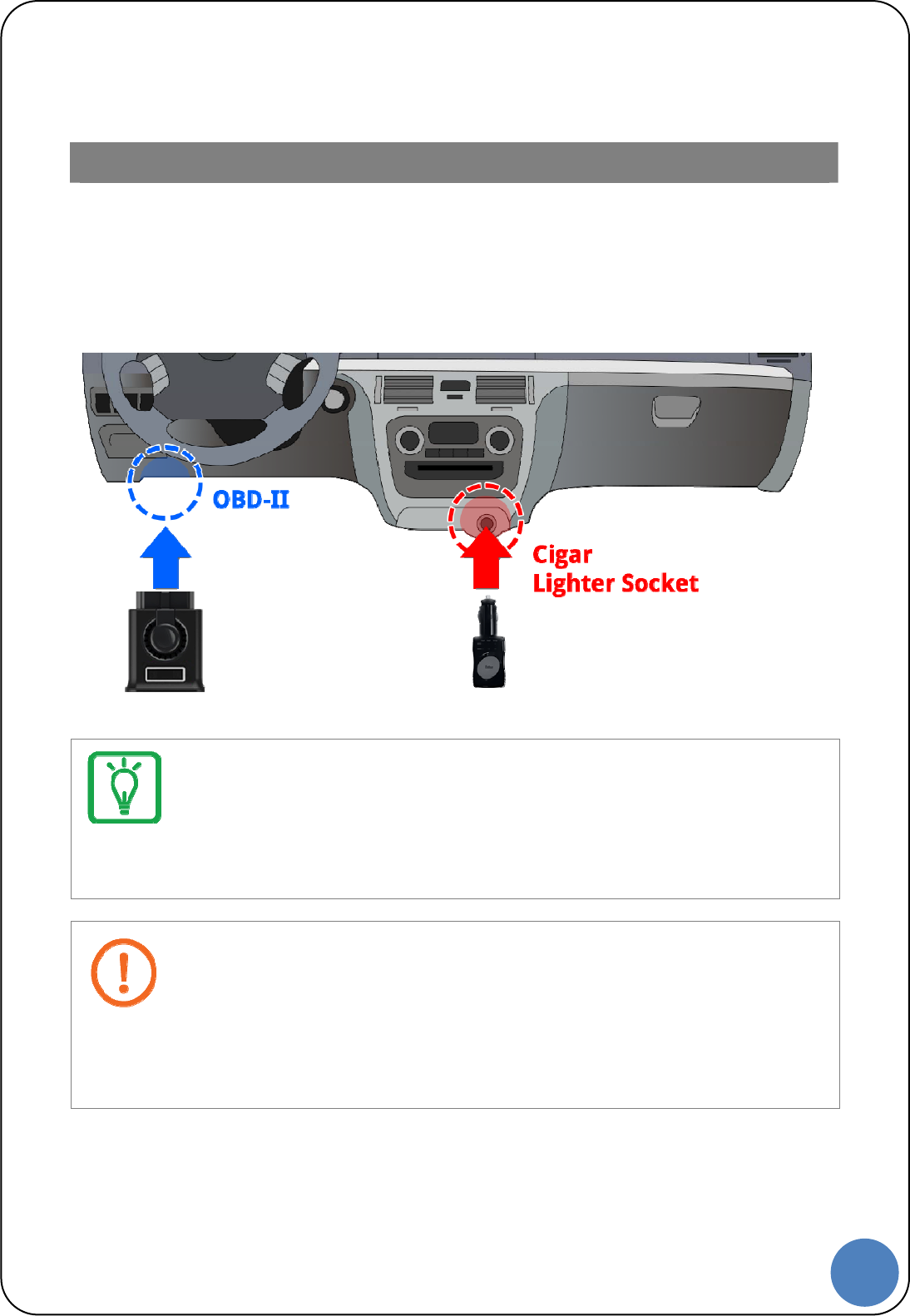
VCI Ⅱ and GDS Trigger Connection
VCI Ⅱ and GDS Trigger must be paired to transfer and save the data for Flight Record
function from the vehicle to VCI Ⅱ module. They are paired by Bluetooth communication
system and must be set up as shown below.
Preparing
Notice
VCI II must be connected to OBD-II connector on the vehicle and VCI II should be turned on.
When the trigger module is connected to the Cigar Lighter Socket, the VCI II power is turned on
automatically and it searches VCI II and connects it.
Caution
VCI Ⅱ must be connected to the OBD-II connector on the vehicle.(Power on)
When the trigger module is connected to the Cigar Lighter Socket, the VCI Ⅱ power is turned on
automatically and it searches VCI Ⅱ and connects it.
9
G |
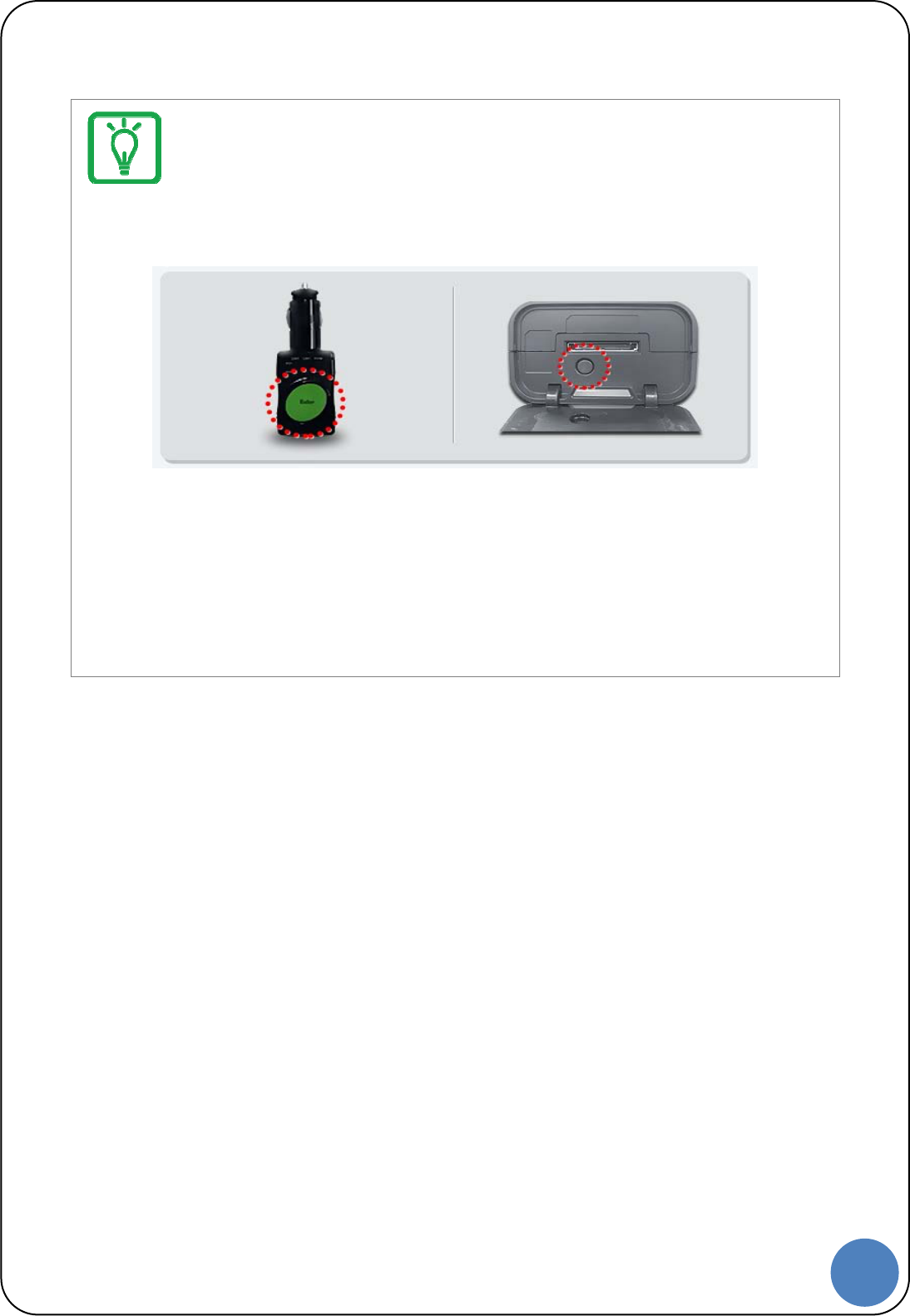
Pairing between VCI Ⅱ and GDS Trigger Module
We, GIT, supply VCI Ⅱ and GDS Trigger Module as a paired status. However, if they are not
paired, follow the instruction below.
1. Turn VCI Ⅱ and GDS Trigger on.
2. Press “Enter” button on GDS Trigger more than 2 seconds.
3. Press “Reset” button on VCI Ⅱ more than 2 seconds, while orange light is flashing
on “Enter” button.
4. Green light flashes on “Enter” button, after pairing between VCI Ⅱ and GDS
Trigger.
10
G |
Screen Layout and Basic
Operation
Screen Layout and Basic Operation
11
G |
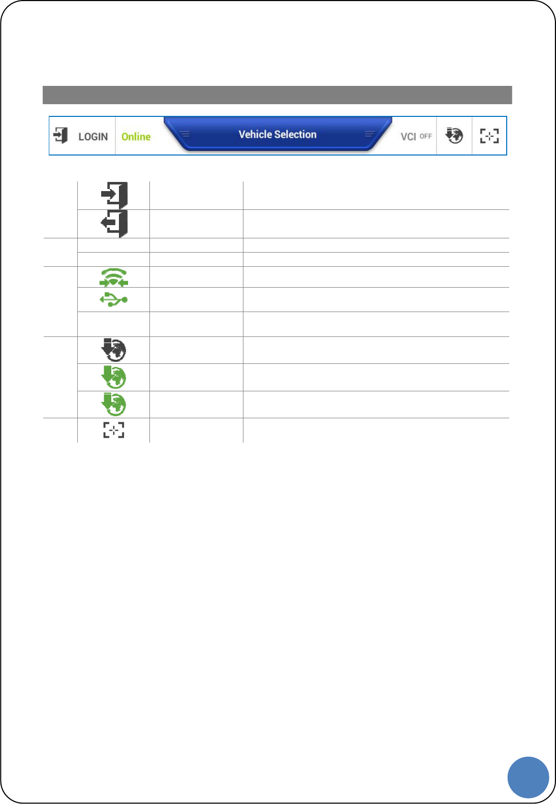
Status Information
Top menu of Screen
Login- Log in (Not certified yet)
1
Logout Log out (Certified)
ONLINE Internet on
2 Off Line Internet off
Lightening VIC Ⅱ connection via WiFi Direct
VCI Ⅱ connection via USB cable.
3
VCI OFF - VCI Ⅱ off
OFF Internet Update
Flashing Downloading Internet Update Files
4
Lighting Complete downloading Internet Update file.
5 Screenshots Capture the Screenshots and write a note on it.
12
G |
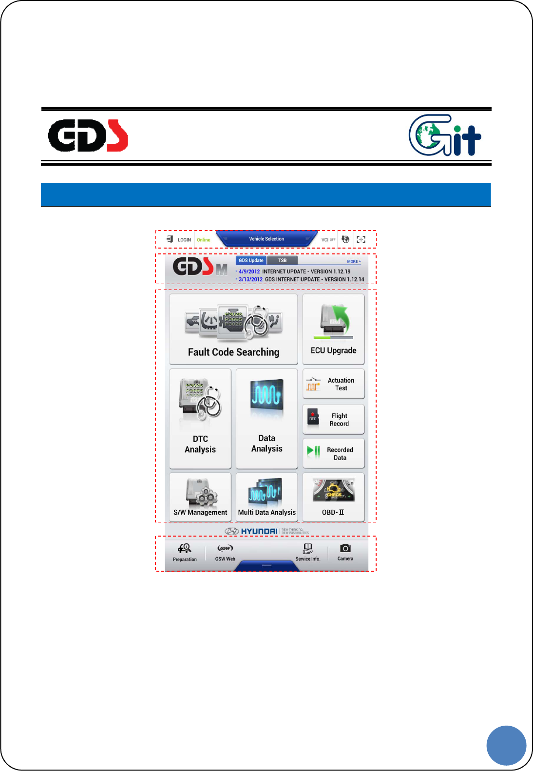
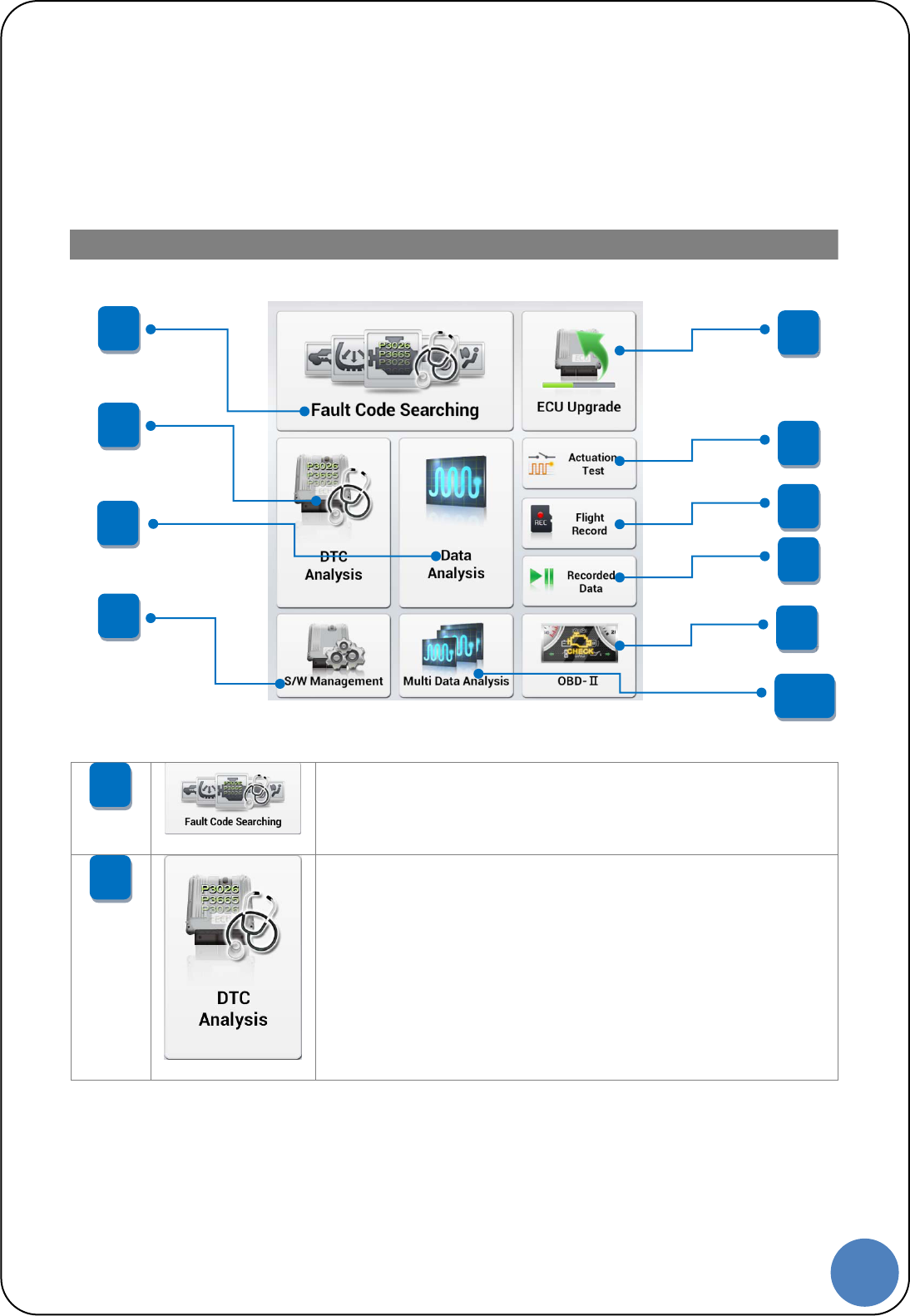
Function Icons
Function to read DTC data saved on the several systems of
the vehicle and display them on the screen at once.
Function to retrieve DTC data from a specific system and retrieve
diagnostic procedures/ TSB data for any DTCs found.
2
1
1
2
5
4
3
6
7
8
9
10
13
G |
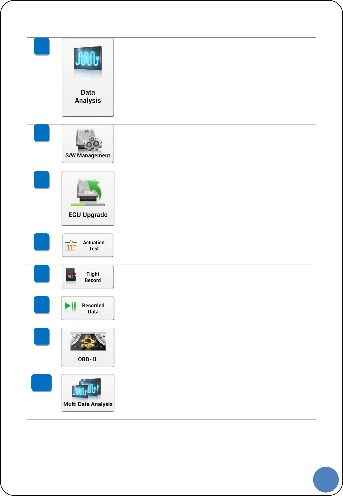
Function to monitor ECU status and input/output information
(Current Data) via communication with ECU.
Function to register or set the information of the vehicle
system via communication with ECU.
Function to upgrade ROM data on ECU to improve the vehicle
performance.
Function to operate / stop the actuator on the vehicle by
force to check its malfunction.
Function to record the ECU input/output information in real
time and to analyze the data in various ways.
Function to view for the data from Data Analysis and Flight
Record.
Function to check the vehicle status via OBD-II
communication with vehicle.
Function to check the input/output information of the
several systems on the vehicle at the same time.
*Only CAN Protocol systems are available.
10
9
8
7
6
5
4
3
14
G |
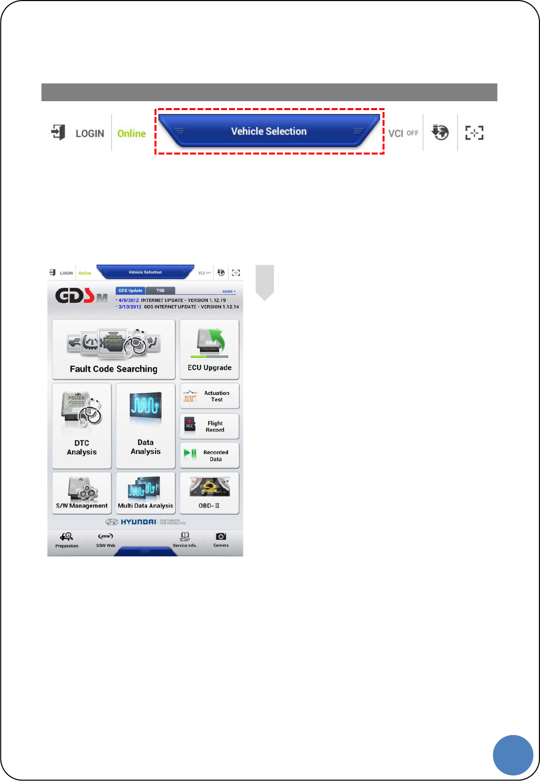
Vehicle Selection
There are two ways to select vehicle for diagnosis: Manual Vehicle
Selection and VIN searching.
To diagnose vehicle properly, follow the instruction for vehicle selection
as shown below.
VIN Searching for Vehicle Selection
Tap “Vehicle Selection” at the top of
the middle on the main screen to go to
“Vehicle Selection” screen.
1
15
G |
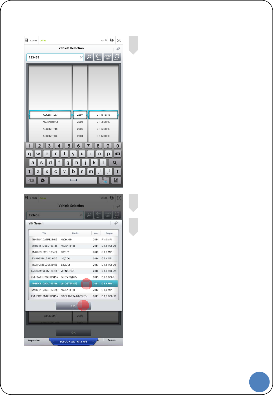
Input the last 6 digits of VIN in the box
Tap VIN that requires to be diagnosed.
Tap “OK” button to save the
model/year/engine information
4
3
2
3
4
16
G |
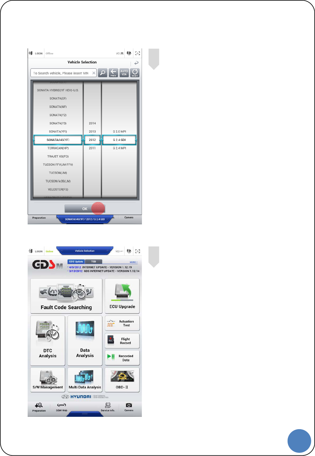
Tap “OK” button to complete vehicle selection.
Manual Vehicle Selection
Tap “Vehicle Selection” at the top of
the middle on the main screen to go to
“Vehicle Selection” screen.
1
5
5
17
G |
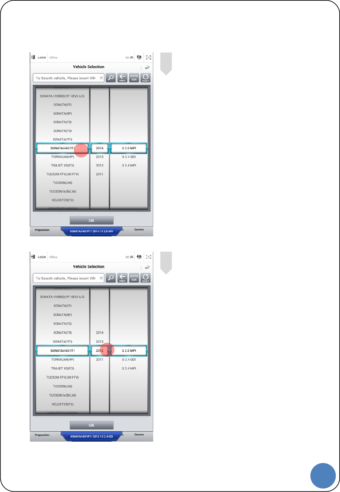
Select vehicle model.
Select Year of vehicle.
3
2
2
3
18
G |
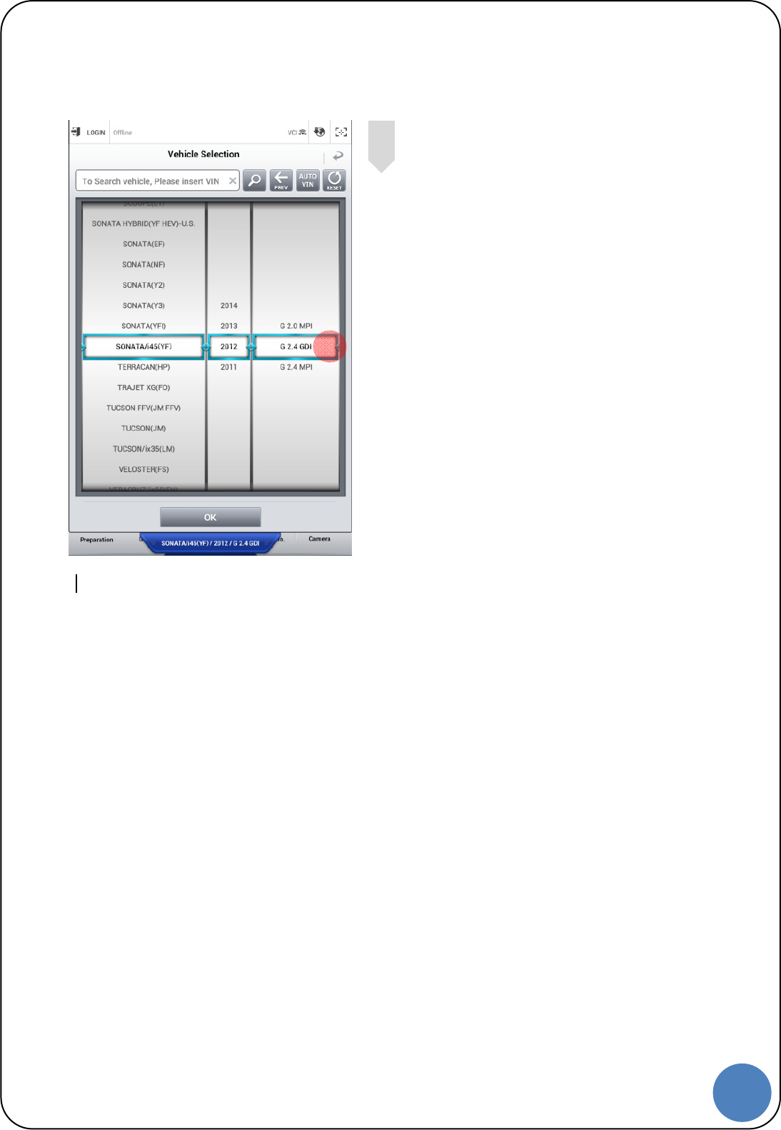
Select engine system.
4
4

19
G |
Appendix
3
20
G |
Notes regarding trademarks
Changes or modifications not expressly approved by the party responsible for
compliance Could void the user’s authority to operate the equipment.
This device complies with part 15 of the FCC Rules. Operation is subject to the
following two conditions:
(1) This device may not cause harmful interference, and
(2) this device must accept any interference received, including interference that may cause
undesired operation.
NOTE:
This equipment has been tested and found to comply with the limits for a Class B digital device,
pursuant to Part 15 of the FCC Rules. These limits are designed to provide reasonable protection
against harmful interference in a residential installation. This equipment generates, uses and can
radiate radio frequency energy and, if not installed and used in accordance with the instructions, may
cause harmful interference to radio communications. However, there is no guarantee that interference
will not occur in a particular installation. If this equipment does cause harmful interference to radio or
television reception, which can be determined by turning the equipment off and on, the user is
encouraged to try to correct the interference by one or more of the following measures:
- Reorient or relocate the receiving antenna.
- Increase the separation between the equipment and receiver.
- Connect the equipment into an outlet on a circuit different from that to which the receiver is
connected.
- Consult the dealer or an experienced radio/TV technician for help.
Indication of any restrictions of use: Data transmission via WLAN/Bluetooth technologies.
This equipment was restricted to indoor use, when operating at WLAN 5 GHz.
Indication of the countries where the equipment is intended to be used:
This equipment may be operated in AT, BE, CY, CZ, DK, EE, FI, FR, DE, GR, HU, IE, IT, LV, LT, LU,
MT, NL, PL, PT, SK, SI, ES, SE, GB, IS, LI, NO, CH, BG, RO, TR
This product is CE marked according to the provision of the R&TTE Directive(1999/5/EC).
Here by G.I.T Co., Ltd.. declares that this product in compliance with the essential requirements
and other relevant provisions of Directive 1999/5/EC
ThisdeviceissoldforuseasaMobileDevice,andtheantennausedforthistransmittermustbe
installedtoprovideaseparationdistanceofatleast20cmfromallpersonstocomplywithFCCRF
exposurecompliancerequirements.
21
G |
Disposal of Old Electrical and
Electronic Equipment
WEEE (Waste Electrical and Electronic Equipment) symbol shown in [Figure 1] is indicated on the
back of the VCI main module, VMI main module, and Trigger module.
Please follow the regulation guide for disposal of Waste Electrical and Electronic Equipment. Use
caution disposing of the Trigger module; it contains a lithium battery. Users must follow the regulations
when replacing or discarding this battery.
Fig. 1. WEEE Symbol
Disposal of Old Electrical & Electronic Equipment (Applicable in the European Union and other
European countries with separate collection systems)
This symbol on the product or on its packaging indicates that this product shall not be treated as
household waste. Instead it shall be handed over to the applicable collection point for the recycling of
electrical and electronic equipment. By ensuring this product is disposed of correctly, you will help
prevent potential negative consequences for the environment and human health, which could
otherwise be caused by inappropriate waste handling of this product. The recycling of materials will
help to conserve natural resources. For more detailed information about recycling of this product,
please contact your local city office, your household waste disposal service or the shop where you
purchased the product.
22
G |
23
G |