G I T GHDM-210000 VCI TERMINAL DEVICE User Manual VCI
G.I.T Co.,Ltd. VCI TERMINAL DEVICE VCI
UserManual.wiki
>
G I T
>
GHDM 210000 User Manual
USERS MANUAL
Navigation menu
Upload a User Manual
Namespaces
Wiki Guide
HTML
PDF
Info
Views
User Manual
Discussion / Help
Navigation
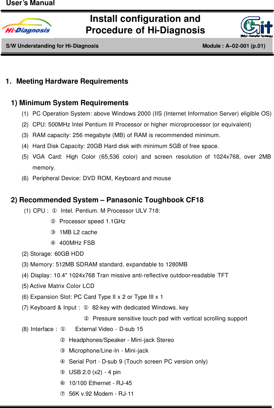
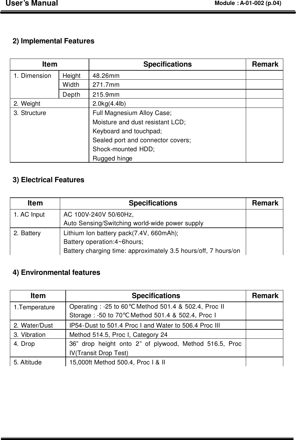
![1 1. VCI Power On To turn on the VCI equipment, first of all, connect DLC cable from vehicle to VCI module and depressing the main switch. If diagnosis connector doesn’t applied for 16 pin connector, in other words, if battery power can’t be supplied from this diagnosis connector to VCI equipment, in this case, cigar power cable must be connected with cigar connector to supply the battery power with ACC stage from the ignition switch. In case of using electric supply from cigar power cable, please connect directly to battery by using battery extension cable. [Figure 1. Main switch of VCI main module] 1) Confirm the VCI operating condition VCI equipment has window for checking the VCI operating condition. This window shows that the condition of each function of VCI by showing with LEDs. Power on/off and method of switch operation H/W understanding for Hi-Diagnosis Module : A–01-005 (p.01) User’s Manual](https://usermanual.wiki/G-I-T/GHDM-210000/User-Guide-581797-Page-2.png)
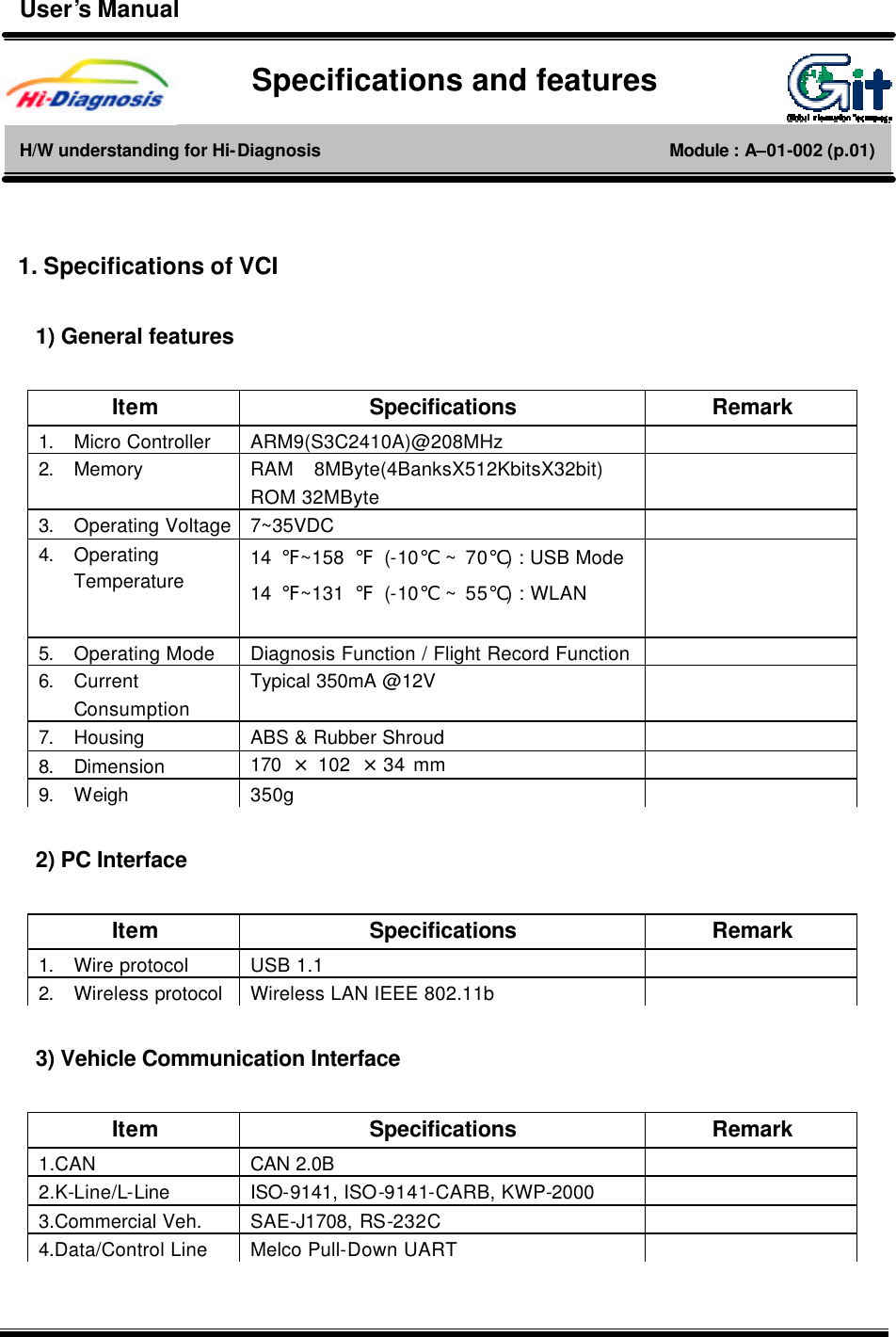
![[Figure 2. LED status on window of VCI main module] ① POWER LED displays with turn VCI equipment on. Color of this LED reflects which function has been running on VCI equipment either diagnosis or flight record mode. Yellow refers to diagnosis mode and red is for flight record mode. ② VEH. COMM The condition of Vehicle Communication can be confirmed by LEDs. It depends on which function has been selected by user such as monitor DTC, sensor output or actuator operation by reading the blinking velocity of this LED with keep Vehicle Communication on. ③ PC COMM As the way of communication between VCI and PC, it also confirmed with displayed LED color. Red color refers to wireless LAN and yellow is for USB cable. 2. VCI Power Off To turn off the VCI equipment, depressing the main switch for about 2.5 seconds or disconnecting the power supply cable. VCI equipment automatically turns off in case of disconnection of power supply cable. User’s Manual Module : A-01-005 (p.02)](https://usermanual.wiki/G-I-T/GHDM-210000/User-Guide-581797-Page-3.png)
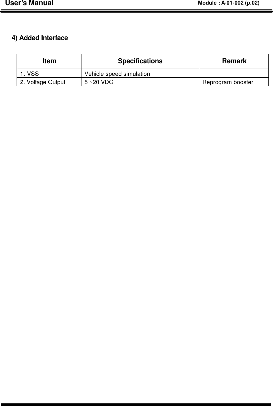
![3. Switch operation of trigger module 1) Switch operation of trigger module (Enter / Cancel) There are buttons for “ENTER” and “CANCEL” on the trigger module. The communication data is stored into memory of VCI by depressing “ENTER” button during the Flight Record mode. And the “ENTER” button can be undone by depressing the “CANCEL” button. 2) Lamp of trigger module (Power / Ready) Trigger module has two different LEDs. The one with red light refers to DC power supplied condition of VCI module and the other yellow light means recording status of communication data after depressing “ENTER” button. [Figure 3. Switches and LEDs of trigger module ] User’s Manual Module : A-01-005 (p.03)](https://usermanual.wiki/G-I-T/GHDM-210000/User-Guide-581797-Page-4.png)
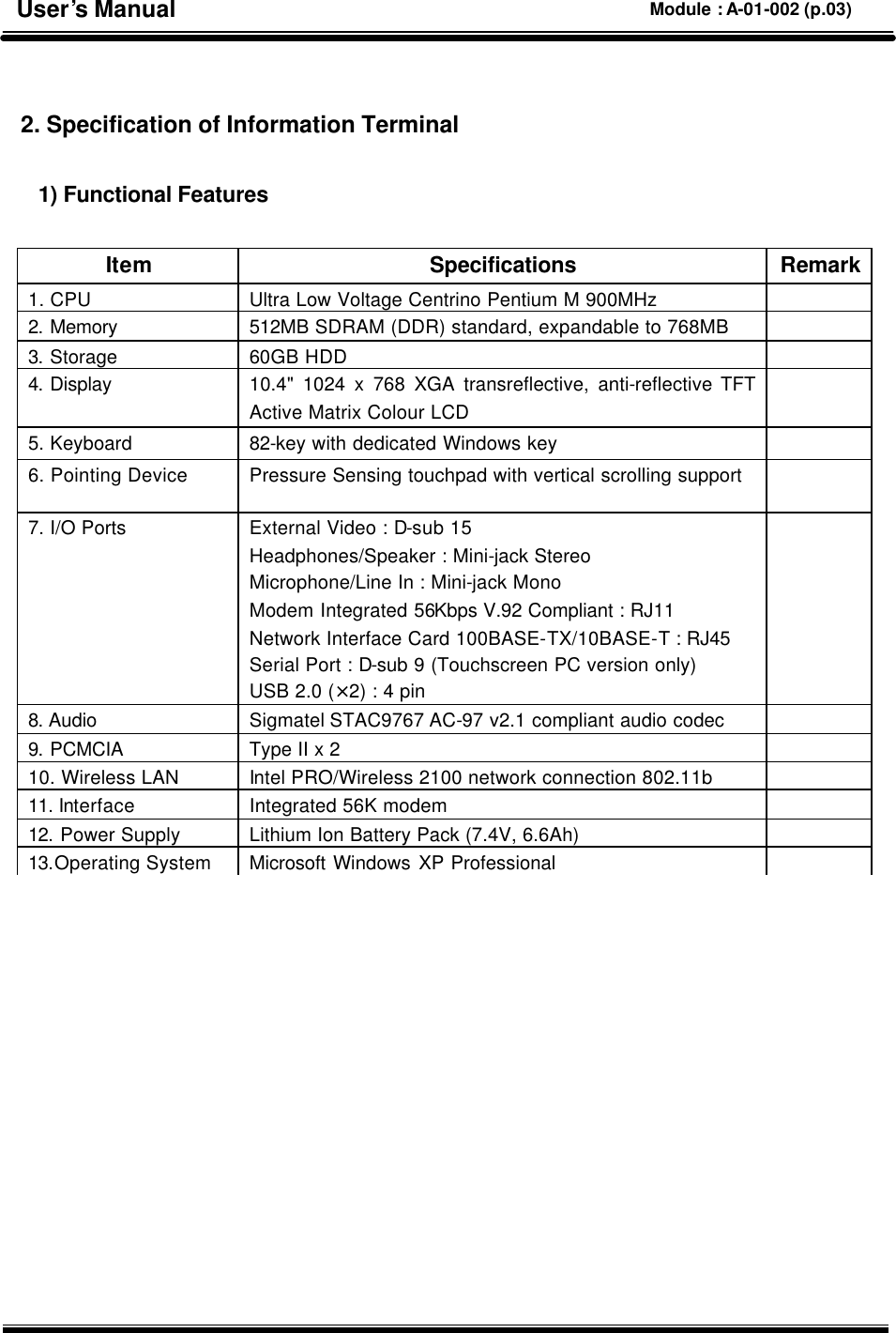
![Trigger module of VCI equipment has two purposes. This trigger module sends the trigger signal to VCI main module when trouble occurrence. And trigger signal is sent to VCI by depressing the trigger button with Flight Record mode. According to this trigger signal, the VCI module starts to store the Flight Record Data. The VCI module receives ON/OFF signal from trigger module. In other words, trigger module detects ignition switch position and then sends ON/OFF signal to VCI module. Therefore the VCI module is turned ON/OFF automatically by turning the ignition switch as driver’s intention. And VCI module finally turns on with the signal from trigger module when turned ignition switch over the ACC stage. At this moment, VCI prepares for communication with ECU. The other purpose of trigger module is also supplies DC power to VCI module connected to the vehicle which isn’t applied for 16 pin(OBD II diagnosis connector) connector. 1. Installation of trigger module and cigar power cable Cigar jack from trigger module and round shape connector with 6pins are each connected with cigar connector on the vehicle and VCI module. Trigger module must be installed at the certain position to avoid disturbing their drive and also be considered that data captures promptly and quickly by sending the signal from trigger module. [Figure 1. Installation of trigger module] Installation of trigger module and cigar power cable H/W understanding for Hi-Diagnosis Module : A–01-004 (p.01) User’s Manual](https://usermanual.wiki/G-I-T/GHDM-210000/User-Guide-581797-Page-5.png)
![[Figure 2. Connection of cigar jack] [Figure 3. Connection of battery extension cable] User’s Manual Module : A-01-004 (p.02)](https://usermanual.wiki/G-I-T/GHDM-210000/User-Guide-581797-Page-6.png)
![1. Vehicle and Control Module Selection If “ScanTool” menu item is selected before the vehicle/system selection through VIN selection, vehicle/system selection window appears as shown in [Figure 1]. Accurate system is necessary for the communication. In Hi-Diagnosis, there is no need to go through additional vehicle selection after the first selection for the use of other functions. System selection screen can be divided into 4 main parts: VIN selection, Configuration of “Scantool” function and “Fault Code Searching” condition, DTC input, and “Comments” input. [Figure 1. Vehicle Selection] Scantool-Communication Open and Retry Hi-Diagnosis program-DIAGNOSIS Module : A –04 –006 (p.01) User’s Manual](https://usermanual.wiki/G-I-T/GHDM-210000/User-Guide-581797-Page-7.png)
![1) VIN Selection There are three ways to select vehicle. ① By Inputting Vehicle Identification Number consists of 17 figure codes combined by letters and numbers. ② By selecting vehicle, model year, and engine ③ By using VIN Auto Detect function (1) Input of VIN with 17-figure codes combined with number and Letter There is a way to input all 17-figure code of VIN in the VIN input box. Another way is to input part of the 17-figure code and choose from the list. First, input all 17-figure code in the VIN input box and click “Go” button. “Vehicle”, “Model year”, “Engine” will automatically be chosen. Control modules of the corresponding vehicle appear for the inputted VIN code. [Figure 2. VIN Input - All of 17 figures] Another way is to input part of the 17-figure VIN code and click “Go” button. Window of VIN list will appear. Choose the corresponding VIN code from the list. User’s Manual Module : A-04-006 (p.02)](https://usermanual.wiki/G-I-T/GHDM-210000/User-Guide-581797-Page-8.png)
![[Figure 3. VIN Input – Part of 17 figures] (2) Method to select Vehicle, Model Year and Engine Select “Vehicle”, “Model year”, and “Engine” in each section for a vehicle, and control modules that can be applied will appear on the window. [Figure 4. Direct selection for vehicle, Model Year and Engine] (3) Method to use VIN auto Detect function If the model year of the selected vehicle is later than 2005 Model Year, then a user can input VIN code by “VIN Auto Detect” function. Establish a connection to communicate VCI module with the vehicle (VCI power On, DLC cable, and etc.) and click “VIN Auto Detect” button to automatically input a VIN code. User’s Manual Module : A-04-006 (p.03)](https://usermanual.wiki/G-I-T/GHDM-210000/User-Guide-581797-Page-9.png)
![2) Control module selection for scantool and fault code searching (1) Selection of control module for scantool By selecting “Vehicle”, “Model Year”, and “Engine” in the “Vehicle Selection”, VCI module for vehicle communication is selected in the “Selected section” in default, for using “Scantool” function. Default setting for “Selected” section is always in “Engine”, and user can change to other control modules. [Figure 5] below shows the state that is set in default as an “Engine”, and [Figure 6] shows the state that is changed into “ANTILOCK BRAKE SYSTEM”. [Figure 5. “ENGINE” selection in “Selected” section] [Figure 6. “ABS” selection in “Selected” section] User’s Manual Module : A-04-006 (p.04)](https://usermanual.wiki/G-I-T/GHDM-210000/User-Guide-581797-Page-10.png)
![(2) Selection of control module for fault code searching “Fault Code Searching” function finds DTC automatically for selected control module through the communication between a VCI and a vehicle. If DTC is found, “By DTC” function on the “Hot Fix” menu can be effective. ① Control module selection Click “Fault Code Searching Turn Off” button in order to change to “Turn On” State, for a use of “Fault Code Searching” function. It is possible to select one or more control module in the “Selected” section in “Turn On” state. Control Modules that will be applied in “Fault Code Searching” will move to the “Selected” section by mouse click. [Figure 7. Control module selection for fault code searching] ② Control module change In order to modify control modules for “Fault Code Searching” after a move to the “Selected” section, double click the control module icon in the “Selected” section. The icon will disappear for the “Selected” section and will move back to the unselected section. It is also possible to add another module to the “Selected” section. However, at least one control module should be in the “Selected” section. User’s Manual Module : A-04-006 (p.05)](https://usermanual.wiki/G-I-T/GHDM-210000/User-Guide-581797-Page-11.png)
![[Figure 8. Control module change] ③ Change of control module for scantool function Among the control modules in the “Selected” section, it is possible to assign a control module as a default setting for the communication during the use of “ScanTool” function. The Icon with the “V” sign on the top, is a default module that will be used for communication. Change in the default communication module is made through the mouse selection of other control modules. The “V” sign will appear on the top of the selected module icon. [Figure 9. Change of control module for scantool function] User’s Manual Module : A-04-006 (p.06)](https://usermanual.wiki/G-I-T/GHDM-210000/User-Guide-581797-Page-12.png)
![(3) Process and result for fault code searching function By Setting and running “Fault Code Searching” function in the “Vehicle Selection” can automatically diagnose DTC during the use of other Hi-Diagnosis functions through the communication between a VCI and a vehicle. The progress rate for the Fault Code Searching will be displayed on the top of the “Fault Code Searching” icon, which is located on the lower section of the Hi-Diagnosis screen. It will be displayed as shown in [Figure 10-1] when there is a communication with the assigned module. When there is a DTC in any of the module, the icon will be displayed as shown in [Figure 10-2]. DTC list can be checked by clicking the icon in the state of [Figure 10-2]. [Figure 10. Process and result for fault code searching] [Figure 10-1] [Figure 10-2] [Figure 10-3] User’s Manual Module : A-04-006 (p.07)](https://usermanual.wiki/G-I-T/GHDM-210000/User-Guide-581797-Page-13.png)
![3) Trouble symptoms selection Select and input vehicle symptom in the “Symptoms in this vehicle” section on the “Vehicle Selection” window. Selection Menu on the left can be categorized into groups of “Engine”, “Transmission”, and “Brake”. The right menu is for the selection of symptom for the selected group on the left. The symptoms are “Hard/No starts”, “Idle-irregularity”, “Engine Stall” and etc. If there is more than one symptom, it is possible to choose symptoms in addition. Double click the item to remove from the selected symptoms. It is possible to use “By Symptom” function in the “Bulletin” menu at the initial page after the completion of vehicle symptom input. “Symptom Analysis” function in the “Guide Diagnosis” menu can also be used. [Figure 11. Input of Symptoms and Comments] 4) Comments Input “Comment” section in the “Vehicle Selection” window is used when user wants to comment on the selected vehicle. In case of Vehicle Identification Number (VIN) is directly inputted in the vehicle selection section, comment will be saved and shown when the same VIN is selected in the future. User’s Manual Module : A-04-006 (p.08)](https://usermanual.wiki/G-I-T/GHDM-210000/User-Guide-581797-Page-14.png)
![2. Communication Open If the system selection is completed, the stage to open a communication with the control module to be diagnosed is necessary for the communication. Check following matters before opening the communication. 1) Ignition switch of a vehicle should be turned on. 2) DLC cable of VCI should be correctly connected to the DLC connector of the vehicle. 3) VCI module power should be turned on. 4) Connection between the PC and VCI should be stable. If the communication is opened, the initial page is shown in dual output mode: DTC diagnosis output and Freeze Frame output. [Figure 12. Communication Open for selected control module] User’s Manual Module : A-04-006 (p.09)](https://usermanual.wiki/G-I-T/GHDM-210000/User-Guide-581797-Page-15.png)
![3. Communication Result After the “Communication Open” communication stays connected if user does not turn off the VCI nor switches the ignition switch to less than On. If there is a disturbance between the communication, connection may be lost. [Figure 13. Result of communication open] User’s Manual Module : A-04-006 (p.10)](https://usermanual.wiki/G-I-T/GHDM-210000/User-Guide-581797-Page-16.png)
![4. Communication Retry If the communication is lost between the PC and the VCI or the VCI and the Vehicle, it is possible to retry connection by going back to the initial page and clicking the “Retry” button. “Retry” button is located in the upper right section of the screen, and retries to make connection for the selected system control module when it is pressed. Following matters should be checked before the communication. 1) Ignition switch of a vehicle should be turned on. 2) DLC cable of VCI should be correctly connected to the DLC connector of the vehicle. 3) VCI module power should be turned on. 4) Connection between the PC and VCI should be stable. [Figure 14. Communication retry for selected control module] User’s Manual Module : A-04-006 (p.11)](https://usermanual.wiki/G-I-T/GHDM-210000/User-Guide-581797-Page-17.png)
![5. Control Module Changing If user wants to connect in different control module in same vehicle at the current page, reselect the control module to communicate with system reselect button. [Figure 15. Control module change] User’s Manual Module : A-04-006 (p.12)](https://usermanual.wiki/G-I-T/GHDM-210000/User-Guide-581797-Page-18.png)